Embed Size (px)
Citation preview

KPK SeriesHigh-Performance
Cut-Off Solutions
Unique Design for Superior Performance in Cut-Off Operations
KPK SeriesHigh-Performance Cut-Off Solutions
Easy Insert Replacement
Strong Clamping Mechanism for Added Safety and Security
Long Tool Life and Stable Machining with UniqueChipbreaker Designs
Jet Coolant-Through Styles Available (JCT)
Toolholder (Blade Type, Shank Type) and InsertLineup Expansion

1
Great for High Pressure Coolant
JCT Series
During cut-off operations, insert cutting widths of only a few millimeters are used to cut to the center of the workpiece.
Cut-off is often used on bottlenecks of a workpiece or during the fi nal process, requiring a trouble-free machining environment.
The shape of the workpiece can be difficult to secure, thus creating rigidity and chattering issues.
The KPK Series features new insert, blade, toolholder and tool block designs for rigid, safe, and secure cut-off operations.
Challenges
SOLUTION
Firm Clamping Power
Durable Performance Advanced Chipbreaker Technology
Long tool life with internal coolantExcellent chip evacuation
High-Rigidity Tool Holder Block
Newly Developed Blade Design High-Performance Insert
High-Performance Cut-Off Solutions
KPK SeriesEasy Insert Replacement Reduces DowntimeHigh Performance, Long Tool Life and Stable Machining with Strong Clamping Mechanism
CUT-OFF SOLUTION
CG Image

2
Easy Insert Replacement1
Firm Insert Clamp Ensures Added Safety and Security2
Reduce down time with fast insert replacement
Turn wrench slightly to release insert
The firmly secured insert uses three contact surfaces to eliminate sliding or chattering
No hammer or screw requiredSelf-clamping
KPKCompetitor A
Load
00 20 40 60 80 100
40
80
120
160
200
Load (N)
Inse
rt o
�set
(μm
)
Insert Deviation Comparison (Internal evaluation)
Measured tool : KPKB32-3 PKM30N-025PM
Cutting Performance Comparison (Internal evaluation)
Cutting Conditions : n = 320 min-1
(constant) , Vc = ~ 100 m/min , f = 0.12 mm/rev , Wet (External coolant) Workpiece : SCM 435 (ø 100) Edge width : 3 mm (PM Chipbreaker)
Good
Cutting Noise and Surface Finish: GoodStable Machining
KPK
Damaged
Chip CloggingScratches on the Finished Surface
Chip entanglementChattering when entering the workpiece
Competitor A
Chip Clogging
Chattering
Competitor B
Chip entanglement
3. V-Shaped Insert Seat2. Back Stop
1. Top Clamp
Optimized insert seating prevents insert movement
Front Contact : Improves stabilityBack Contact : Prevents insert slipping
Separate Contact Surfaces
Prevents insert retraction and makes mounting inserts easier
Holds the insert in place

3
Competitor CCompetitor BKPK (PR1625)
0.000 20 40 60 80 100 120 140
0.03
0.06
0.09
0.12
0.15
Cutting Time (min)
Edge
wea
r am
ount
(m
m)
KPK Competitor B Competitor C
Chip entanglement
Chip entanglement
Chip entanglement
Chip cloggingProcessing noise large
f (m
m/r
ev)
0.18
0.12
0.08
Unique Chipbreaker for Long Tool Life and Stable Machining3
Cutting Conditions : n = 955 min-1
(constant), Vc = ~ 150 m/minf = 0.12 mm/rev (~ ø 10 : f = 0.05 mm/rev) Wet (External Coolant)Workpiece : SCM 415 (ø 50) Edge width : 3 mm (PM Chipbreaker)
Cutting Conditions : n = 90 min-1
(Constant) , Vc = ~ 140 m/min , f = 0.06 mm/rev , Wet (External Coolant) KPKB32-3 PKM30N-025PM PR1625
(User evaluation)
Cutting Conditions : n = 1,450 min-1
(Constant) , Vc = ~ 173 m/min , f = 0.05 mm/rev (Inching: 1 mm)Wet (External coolant) KPKB32-3 PKM30N-025PM PR1535
(User evaluation)
Cutting Conditions : n = 780 min-1
(constant) , Vc = ~ 120 m/min , Wet (External Coolant)Workpiece : SCM 415 (ø 50) Blade width : 3 mm (PM Chipbreaker)
Advanced chipbreaker technology inherited from KGD lineup provides excellent chip control
External Coolant External Coolant
Insert grade Insert grade
For Steel : PR1625For Stainless steel : PR1535For Cast Iron and Aluminum : GW15
For Steel : PR1625For Stainless steel : PR1535
For Tough edge and High-feed machining
PH Chipbreaker
General use
PM Chipbreaker
Wear Resistance Comparison (Internal Evaluation) Chip Control Comparison (Internal evaluation)
Rings(SUJ2)
Adaptor(SUS316)
ø470
15
ø490
ø38
45900
3
KPK Competitor E
KPK 34 pcs/corner
Competitor D 25 pcs/corner Low vibration and good cutting noise
SOLUTION 1 Tool Life x 1.3Stable chip curl SOLUTION 2
Machining efficiency double in Stainless steelAchievement of stable machining
4
Competitor C
KPK
0 4643
Blade overhang amount (mm)
Chattering occurred
External Coolant Internal Coolant (JCT)7Mpa1Mpa
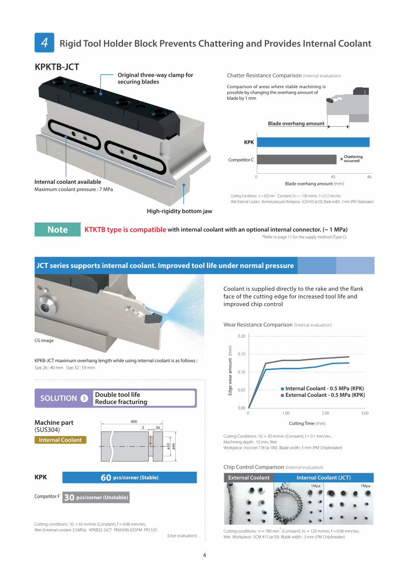
Internal Coolant - 0.5 MPa (KPK)External Coolant - 0.5 MPa (KPK)
0.000 1.00 2.00 3.00
0.05
0.10
0.15
0.20
Cutting Time (min)
Edge
wea
r am
ount
(m
m)
Rigid Tool Holder Block Prevents Chattering and Provides Internal Coolant4
Cutting Conditions : n = 650 min-1
(Constant), Vc = ~ 100 m/min, f = 0.12 mm/revWet (Internal Coolant : Normal pressure) Workpiece : SCM 435 (ø 50), Blade width : 3 mm (PM Chipbreaker)
Cutting conditions : Vc = 65 m/min (Constant), f = 0.06 mm/rev, Wet (Internal coolant 3.5MPa) KPKB32-3JCT PKM30N-025PM PR1535
(User evaluation)
Internal coolant available
High-rigidity bottom jaw
Original three-way clamp for securing blades
Coolant is supplied directly to the rake and the flank face of the cutting edge for increased tool life and improved chip control
Cutting conditions : n = 780 min-1
(Constant), Vc = 120 m/min, f = 0.08 mm/rev, Wet Workpiece : SCM 415 (ø 50) Blade width : 3 mm (PM Chipbreaker)
Comparison of areas where stable machining is possible by changing the overhang amount of blade by 1 mm
KPKB-JCT maximum overhang length while using internal coolant is as follows :Size 26 : 40 mm Size 32 : 59 mm
Internal Coolant
KPKTB-JCTChatter Resistance Comparison (Internal evaluation)
Chip Control Comparison (Internal evaluation)
Machine part(SUS304)
ø46
ø30
36900
3
KPK
Competitor F
60 pcs/corner (Stable)
30 pcs/corner (Unstable)
Maximum coolant pressure : 7 MPa
Blade overhang amount
Note KTKTB type is compatible with internal coolant with an optional internal connector. (~ 1 MPa)
Cutting Conditions : Vc = 30 m/min (Constant), f = 0.1 mm/rev, Machining depth : 10 mm, WetWorkpiece : Inconel 718 (ø 100) Blade width: 3 mm (PM Chipbreaker)
Wear Resistance Comparison (Internal evaluation)
SOLUTION 3 Double tool lifeReduce fracturing
JCT series supports internal coolant. Improved tool life under normal pressure
CG Image
*Refer to page 11 for the supply method (Type C).

5
Blade dimensions
Description Stoc
k
Cutting Dia. Dimensions (mm)
EdgeWidth(mm)
Drawing
Parts
Applicable Inserts
Applicable Tool Holder Block
Insert Wrench Coolant Plug Screw Wrench
CUTDIA *H HF B LF A CW
KPKB 26-1JCT 35
26 21.4
2.6
110
1.4 1.6
Fig. 1
LPW-5 CCP-4 SB-4065TR FT-15
PKM16…
KPKTB -26JCT
KTKTB -26
26-2JCT 50 1.82.0
2.4
PKM20…
PKM24…
26-3JCT 75
-
2.6 3.0
Fig. 2
PKM30…
26-4JCT 80 3.4 4.0 PKM40…
26-5JCT 80 4.24.8
5.0
PKM48…
PKM50…
KPKB 32-1JCT 35
32 25.0
2.6
150
1.4 1.6
Fig. 1
PKM16…
KPKTB -32JCT
KTKTB -32
KTKTBF -32
32-2JCT 50 1.82.0
2.4
PKM20…
PKM24…
32-3JCT 100
-
2.6 3.0
Fig. 2
PKM30…
32-4JCT 100 3.4 4.0 PKM40…
32-5JCT 120 4.24.8
5.0
PKM48…
PKM50…
32-6JCT 120 5.4 6.0 PKM60…
: Standard Stock
Coolant Plug ScrewTightening Torque 3.0 N m
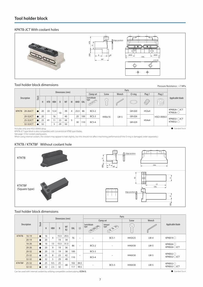
Pressure Resistance : ~7 MPa
Minimum /maximum overhang length while using internal coolantDescription Overhang Length
Blade Tool Holder Block Min. Max.KPKB26-1JCT
KPKTB20-26JCT
15 34.5
KPKB26-2/3/4JCT 20 40
KPKB26-5JCT 23 43
KPKB32-1JCT
KPKTB20-32JCT 18
49KPKTB25-32JCT13
KPKTB32-32JCT
KPKB32-2/3/4JCT
KPKTB20-32JCT 27.5
59KPKTB25-32JCT22.5
KPKTB32-32JCT
KPKB32-5/6JCT
KPKTB20-32JCT 31.5
63KPKTB25-32JCT26.5
KPKTB32-32JCT
JCT JCT
Overhang Length
See page 14 for how to attach insert.When using internal coolant with KTKTB, KTKTBF type tool holder blocks, coolant supply piping (CCN -5) sold separately.*H : Length between virtual vertices
Blades
KPKB-JCT With coolant holes
A
150°
H HF
6° CW
BLF
CUTDIA
LF
A
CW6°
150°
HFH
CUTDIA
Fig.1 Fig.2

6
KPKB Without coolant hole
AOHNLF
H HF
6°
150°
CUTDIA
B
CW
CUTDIA
LF 150°
6°
A
CW
OHN
HHF
Blade dimensions
Description Stoc
k
Cutting Dia. Dimensions (mm)
EdgeWidth(mm)
Drawing
Parts
Applicable Inserts Applicable Tool Holder BlockInsert Wrench
CUTDIA *H HF B LF A CW
KPKB 19-1 32
19 15.7
2.6
86
1.4 1.6 Fig.1
LPW-5
PKM16…
KTKTB -1919-2 40 - 1.8
2.0
2.4Fig.2
PKM20…
PKM24…
KPKB 26-1 35
26 21.4
2.6
110
1.4 1.6 Fig.1 PKM16…
KPKTB -26JCT
KTKTB -26
26-2 50
-
1.82.0
2.4
Fig.2
PKM20…
PKM24…
26-3 75 2.6 3.0 PKM30…
26-4 80 3.4 4.0 PKM40…
26-5 80 4.24.8
5.0
PKM48…
PKM50…
KPKB 32-1 35
32 25.0
2.6
150
1.4 1.6
Fig.1
PKM16…
KPKTB -32JCT
KTKTB -32
KTKTBF -32
32-2 50 1.82.0
2.4
PKM20…
PKM24…
32-3 100
-
2.6 3.0
Fig.2
PKM30…
32-4 100 3.4 4.0 PKM40…
32-5 120 4.24.8
5.0
PKM48…
PKM50…
32-6 120 5.4 6.0 PKM60…
: Standard StockSee page 14 for how to attach insert.*H : Length between virtual vertices
Blades
Fig.1 Fig.2
7
Edge position
2-G1/8
B
HTB
MHD
H
MHDOAL
WF
MHBH
JCT JCT
KTKTB
KTKTBF(Square type)
Can be used with internal coolant by utilizing compatible coolant piping (CCN-5).
Tool holder block dimensions
Description Stoc
k
Dimensions (mm)Parts
Applicable bladeClamp set Screw Wrench
H HBH B WFB2 OAL LS
KTKTB 16-19 164
15.5 29.576 – – BCS-1 HH5X25 LW-4 KPKB19-
20-19 20 19 34
16-26 16 13 15.5 31.586 – BCS-2 – HH6X30 LW-5
KPKB26-KPKB26- JCT20-26 20 9 19 36
20-32 20 13 19 38 100
–
BCS-3
– HH6X30 LW-5KPKB32-KPKB32- JCT
25-32 25 8 23 42110 BCS-4
32-32 32 5 29 48
KTKTBF 25-32 25 9.5 2548
102 84.5– BCS-5 HH6X30 LW-5
KPKB32-KPKB32- JCT32-32 32 2.5 32 117 99.5
: Standard Stock
Switchblade type
Integral type
KTKTB / KTKTBF Without coolant hole
Tool holder block
KPKTB-JCT With coolant holes
Description Stoc
k
Dimensions (mm)Parts
Applicable bladeClamp set Screw Wrench O-ring Plug 1 Plug 2
H HTB HBH B WF M MHD OAL
KPKTB 20-26JCT 20 33 12.4 19
39 4 23.5 86 BCS-2
HH6x16 LW-5
GR-020 HS3x4
HSG1/8X8.0
KPKB26- JCTKTKB26-
20-32JCT 20
41
16 40
5
25 100 BCS-3 GR-026
HS4x4KPKB32- JCTKTKB32-
25-32JCT 25 11 23 44 30 110 BCS-4 GR-029
32-32JCT 32 5 29 50
: Standard StockIncludes only one HSG1/8X8.0 plug.KPKTB-JCT type block is also compatible with conventional KTKB type blades.See page 13 for coolant piping parts.When using internal coolant, the coolant may appear to leak slightly, but this should not affect machining performance.(If the O-ring is damaged, order separately.)
Switchblade type
HBH
H
BWF
Edge position
OAL
LSOAL
B2
HBH
HB
Edge position
Pressure Resistance : ~7 MPaTool holder block dimensions

8
Toolholder Dimensions
Description
Stock Cutting Dia. Dimensions (mm)
Edge Width(mm)
Drawing
Parts
Applicable Inserts
Insert Wrench
R L CUTDIA H HF HBH B LF LH WF HBL CW
KPKH R/L 2020K-2 3820 20
520 125
33.1 19.15 33.12.0
2.4Fig.2
LPW-5
PKM20…
PKM24…
2020K-3 52
-
3418.75
-
3.0
Fig.3
PKM30…2525M-3 53 25 25 25 150 23.75
2020K-4 62 20 20 20 12540.5
18.354.0 PKM40…
2525M-4 68
25 25 25 150
23.35
2525M-5 79 45.9 22.954.8
5.0
PKM48…
PKM50…
KPKH R/L 2020K-3D35 35 20 20
-
20 12532.5
18.75
-
3.0
Fig.1
PKM30…2525M-3D45 45 25 25 25 150 23.75
2020K-4D45 45 20 20 20 12535
18.354.0 PKM40…
2525M-4D45 45 25 25 25 150 23.35
: Standard StockSee page 14 for how to attach insert.
Toolholder Dimensions
Description
Stock Cutting Dia. Dimensions (mm)
Edge Width(mm)
Drawing
Parts
Applicable Inserts
Insert Wrench Plug
R L CUTDIA H HF HBH B LF LH WF HBL MHD CW
KPKH R/L 2020K-2JCT 38 20 20 5 20
125
35.1 19.15 35.1 892
2.4Fig.2
LPW-5 HSG1/8X8.0
PKM20…
PKM24…
2020K-3JCT 52 36
18.75 37 883.0
Fig.1PKM30…
2525K-3JCT 53 25 25 - 25 23.75 - 89 Fig.3
2020K-4JCT 62 20 20 5 2042.5
18.35 42 834.0
Fig.1PKM40…
2525K-4JCT 68 25 25 - 25 23.35 - 82 Fig.3
: Standard StockSee page 14 for how to attach insert.See page 13 for coolant piping parts.
Pressure Resistance : ~15 MPa
KPKH Without coolant hole
KPKH - JCT With coolant holes
HBL
LH
BH
BH
CW
WF
WF
CW
HBLHBHMHD
LHLH
HF
HF
6° 6°
CUTDIA
G1/8 G1/8 G1/8
G1/8
LF
CUTDIAMHDLF
Toolholder
BH
BH
CW CWLH LH
HF
6° 6°
HBL
LH
HBH
CUTDIALF
HF
CUTDIALF
WF
WF
*KPKH R/L2020K-2…
shows above f igure
Fig.2
Fig.2
Fig.1
Fig.1
Fig.3
Fig.3
Right-hand shown
Right-hand shown
*KPKH R/L 2020K-2JCT… shows above f igure

9
Applicable Inserts
Shape DescriptionDimensions (mm) Angle MEGACOAT NANO Carbide
CW RE PSIR R/L PR1625 PR1535 GW15
With
out l
ead
angl
e
General use
PKM 16N-015PM 1.6 0.15
–
20N-020PM 2.0 0.20
24N-020PM 2.4 0.20
30N-025PM 3.0 0.25
40N-030PM 4.0 0.30
48N-030PM 4.8 0.30
50N-030PM 5.0 0.30
60N-035PM 6.0 0.35
Tough Edge
PKM 20N-020PH 2.0 0.20
–
30N-030PH 3.0 0.30
40N-030PH 4.0 0.30
50N-030PH 5.0 0.30
60N-040PH 6.0 0.40
R L R L R L
With
lead
ang
le
PKM 16 R/L-015PM-6D 1.6 0.15
6 °
20 R/L-020PM-6D 2.0 0.20
24 R/L-020PM-6D 2.4 0.20
30 R/L-025PM-6D 3.0 0.25
40 R/L-030PM-6D 4.0 0.30
50 R/L-030PM-6D 5.0 0.30
: Standard Stock
Right-hand Shown
Recommended Cutting Conditions 1st recommendation 2nd recommendation
Workpiece
Cutting speed Vc (m/min) Feed f (mm/rev)
RemarksMEGACOAT NANO Carbide Edge Width CW (mm)
PR1625 PR1535 GW15 1.6 2 ~ 4 4.8 ~ 6
Carbon Steel (SxxC, etc.) 80 – 220 80 – 220 —0.03 – 0.12 0.08 – 0.18 0.10 – 0.22
Wet
Alloy Steel (SCM etc.) 70 – 200 70 – 200 —
Stainless steel (SUS304, etc.) 60 – 150 60 – 150 — 0.03 – 0.08 0.06 – 0.12 0.08 – 0.15
Cast Iron (FC, FCD, etc.) — — 50 – 100 0.03 – 0.08 0.08 – 0.18 0.10 – 0.22
Aluminum alloy — — 200 – 4500.03 – 0.08 0.08 – 0.18 0.10 – 0.22
Brass — — 100 – 200
Workpiece
Cutting speed Vc (m/min) Feed f (mm/rev)
RemarksMEGACOAT NANO Carbide Edge Width CW (mm)
PR1625 PR1535 GW15 2 3 ~ 4 5 ~ 6
Carbon Steel (SxxC, etc.) 80 – 220 80 – 220 —0.10 – 0.22 0.15 – 0.28 0.15 – 0.35
Wet
Alloy Steel (SCM etc.) 70 – 200 70 – 200 —
Stainless steel (SUS304, etc.) 60 – 150 60 – 150 — 0.05 – 0.12 0.08 – 0.15 0.08 – 0.18
Cast Iron (FC, FCD, etc.) — — — — — —
Aluminum alloy — — —— — —
Brass — — —
Reduce feed to 1/2 ~ 1/3 at the center of the workpiece.
Reduce feed to 1/2 ~ 1/3 at the center of the workpiece.
PM Chipbreaker
PH Chipbreaker
RE
RE
CW±0
.03
RE
RE
CW±0
.03
RE
PSIRR
CW±0
.03

10
Machining Ef f iciency
Chip controlSurface f inish
KPK
Competitor G
Good
Machining E�ciency
x 2.0
f = 0.18 mm/rev
f = 0.09 mm/rev
Tool life Tool life
x 1.8KPK
Competitor H
1,500 pcs/corner (Stable)
800 pcs/corner (Unstable)
HELLOStable Cut-off for Your Work
Case Studies
KPK showed good chip control and finished surface with increased feed rates.The machining efficiency ratio was doubled. KPK improves insert mounting speeds.
(User evaluation)
Competitor H was unstable with a sudden fracture. KPK increased tool life by 1.8 times that of competitor H. Stable machining with good cutting edge.
(User evaluation)
Vc = 90 m/minf = 0.18 mm/revWet (External coolant)Overhang length : 70 mmKPKB32-3 PKM30N-025PM PR1535
Rings Forgingn = 1,530 min-1 (Constant)Vc = ~ 100 m/minf = 0.09 mm/revWet (External coolant)Overhang length : 22 mmKPKB26 -3 PKM30N-025PM PR1625
Machine part SNCM2027
ø240
ø8
12
ø20

11
B : VDI Holder Assembly
BladesKPKB-JCT
BladesKPKB-JCT
BladesKPKB-JCT
Tool holder blockKPKTB-JCT
Tool holder blockKPKTB-JCT / KTKTB
VDI - Tool Holder(Internal coolant type)
Tool holder blockKPKTB-JCT
Piping parts
Coolant supply pipeCCN-5
A : Coolant Hose Assembly Maximum coolant pressure : 7 MPa
C : Coolant Pipe Assembly Maximum coolant pressure : 1 MPa
Coolant supply pipe mounting method
Attach to the blade with the supplied screwForm pipe to the required shape and connect it to the piping of the machine.
Supplies according to machine specif ications and requirements
Maximum coolant pressure : 7 MPa(Internal coolant type)
See page 13
Coolant Plug to be removed
Internal coolant supply method (Blade type)
See page 13
Complete Installation
Complete Installation
Complete Installation
12
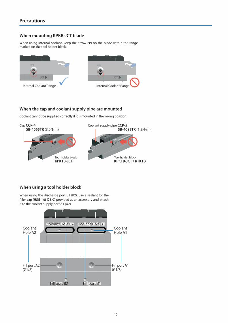
When using the discharge port B1 (B2), use a sealant for the filler cap (HSG 1/8 X 8.0) provided as an accessory and attach it to the coolant supply port A1 (A2).
When using a tool holder block
Tool holder blockKPKTB-JCT
Tool holder blockKPKTB-JCT / KTKTB
Coolant cannot be supplied correctly if it is mounted in the wrong position.
When the cap and coolant supply pipe are mounted
Cap CCP-4SB-4065TR (3.0N m)
Coolant supply pipe CCP-5SB-4085TR (1.5N m)
Internal Coolant Range Internal Coolant Range
JCT JCT
When using internal coolant, keep the arrow ( ) on the blade within the range marked on the tool holder block.
When mounting KPKB-JCT blade
Coolant Hole B2 Coolant Hole B1
Fill port B2 Fill port B1
Coolant Hole A2
Fill port A2(G1/8)
Fill port A1(G1/8)
Coolant Hole A1
Precautions
13
<Piping Installation Guide>
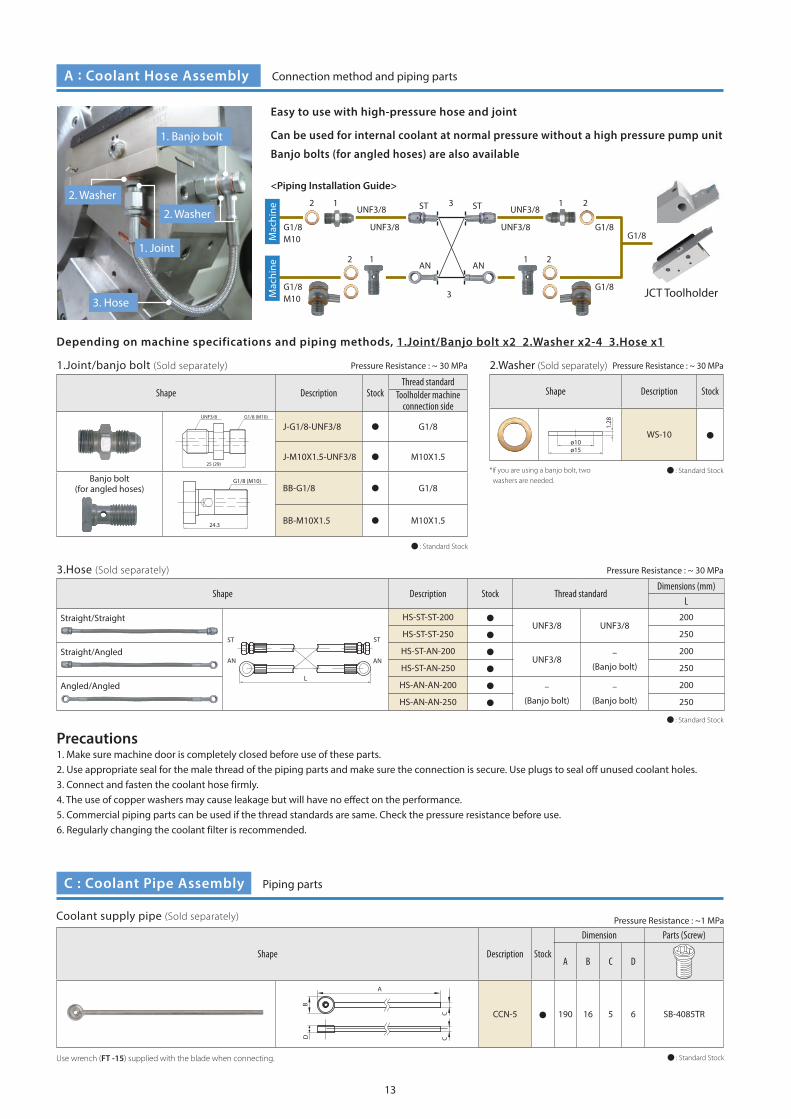
Can be used for internal coolant at normal pressure without a high pressure pump unit
Banjo bolts (for angled hoses) are also available
Precautions1. Make sure machine door is completely closed before use of these parts.2. Use appropriate seal for the male thread of the piping parts and make sure the connection is secure. Use plugs to seal off unused coolant holes.3. Connect and fasten the coolant hose firmly.4. The use of copper washers may cause leakage but will have no effect on the performance.5. Commercial piping parts can be used if the thread standards are same. Check the pressure resistance before use.6. Regularly changing the coolant filter is recommended.
1.Joint/banjo bolt (Sold separately)
Shape Description StockThread standard
Toolholder machine connection side
25 (29)
G1/8 (M10) UNF3/8
J-G1/8-UNF3/8 G1/8
J-M10X1.5-UNF3/8 M10X1.5
Banjo bolt(for angled hoses)
G1/8 (M10)
24.3
BB-G1/8 G1/8
BB-M10X1.5 M10X1.5
2.Washer (Sold separately)
Shape Description Stock
1.28
ø15ø10
WS-10
3.Hose (Sold separately)
Shape Description Stock Thread standardDimensions (mm)
L
Straight/Straight
L
ST ST
AN AN
HS-ST-ST-200UNF3/8 UNF3/8
200
HS-ST-ST-250 250
Straight/Angled HS-ST-AN-200UNF3/8
–
(Banjo bolt)
200
HS-ST-AN-250 250
Angled/Angled HS-AN-AN-200 –
(Banjo bolt)
–
(Banjo bolt)
200
HS-AN-AN-250 250
Easy to use with high-pressure hose and joint
Depending on machine specifications and piping methods, 1.Joint/Banjo bolt x2 2.Washer x2-4 3.Hose x1
2. Washer
3. Hose
*If you are using a banjo bolt, two washers are needed.
1. Joint
2. Washer
1. Banjo bolt
Shape Description Stock
Dimension Parts (Screw)
A B C D
CCN-5 190 16 5 6 SB-4085TR
: Standard Stock
: Standard Stock
: Standard Stock
: Standard Stock
B
C
D C
A
Pressure Resistance : ~1 MPaCoolant supply pipe (Sold separately)
Use wrench (FT -15) supplied with the blade when connecting.
A : Coolant Hose Assembly
C : Coolant Pipe Assembly
Connection method and piping parts
Piping parts
Pressure Resistance : ~ 30 MPa Pressure Resistance : ~ 30 MPa
Pressure Resistance : ~ 30 MPa
12 23 1
12 2
3
1M
achi
neM
achi
ne
G1/8M10
G1/8M10
UNF3/8 ST ST
AN AN
UNF3/8
UNF3/8
UNF3/8G1/8
G1/8
G1/8 JCT Toolholder
14
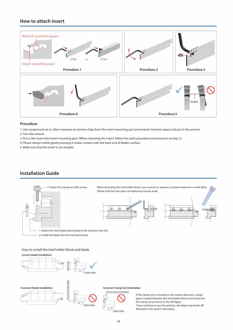
Procedure.1
Procedure.4 Procedure.5
Procedure.2
KPKB or KPKHInsert mounting part
Incorrect blade installation
Correct blade installation
How to install the tool holder block and blade
Datum surface
Incorrect Clamp Set Orientation
3. Fasten the clamp set with screws.
2. Install the blade into the tool block body.
Incorrect Clamp Set Orientation
Wro
ng cu
tting
edge
heigh
tBl
ade h
eight
If the clamp set is mounted in the reverse direction, a large gap is created between the tool holder block main body and the clamp set as shown in the left �gure. If you continue to use the product, the blade may break o�. Reinstall in the correct orientation.
Datum surface
Datum surface
1. Attach the tool holder block body to the machine tool rest.
When mounting the tool holder block, use a wrench or spanner as shown below for a small lathe.Please note that the space for fastening may be small.
Procedure1. Use compressed air or other measures to remove chips from the insert mounting part and wrench insertion space and put in the wrench. 2. Turn the wrench. 3. Put in the insert into insert mounting part. (When removing the insert, follow the same procedure and remove it at step 3.)4. Please clamp it while gently pressing it makes contact with the back end of blade’s surface.5. Make sure that the insert is set straight.
Wrench insertion space
Procedure.3
Insert
How to attach insert
Installation Guide

1. Set cutting edge height 0.1mm above core height.2. Machining with ample supply of coolant is recommended.3. Machine at constant speeds to gain stable tool life.4. Make the cut-off as close as possible to the chuck.5. To prevent impacts, reduce feed rate by 1/2 ~ 1/3 when nearing the center of the workpiece.Excessive use of the insert may cause chipping or damage to the holder.
Han
ded
inse
rt w
ith le
ad a
ngle N (Neutral) R (Right hand) L (Left hand)
Inserts with lead angle (PSIR R/L) reduce burrs at cut-off machining. The larger the lead angle (PSIR R/L), the smaller the cutting force. The feed also needs to be smaller.
Right hand (R) Lead Neutral Neutral
Solid
Wor
kpie
ce
Right hand (R) Lead Neutral Neutral
Hol
low
Wor
kpie
ce (P
ipe)
PSIRR PSIRL
Lead Angle Direction and Usage
Machining Precautions
1. If there is no restriction on the finished shape, use an insert without lead angle.2. Insert with lead angle is recommended to prevent remaining boss.3. If you want to make the remaining boss smaller when machining small or thin parts, use insert with lead angle.
PSIRR PSIRLPSIRR PSIRL
Workpiece
Center Height (Cutting Edge Height)
The information contained in this brochure is current as of April 2021.Duplication or reproduction of any part of this brochure without approval is prohibited.
CP459-2© 2021 KYOCERA Corporation