Embed Size (px)
Citation preview

Technical Guide
High Performance Electrical Double-Layer CapacitorsDMF & DMT Series
www.murataamericas.com/edlc

High Performance Electrical Double-Layer Capacitors
1
Contents1. The Structure and Principles of Electrical Double-Layer Capacitors
1-1. Principles of Electrical Double-Layer Capacitors (EDLC) 1-2. Structure of EDLC 1-3. Equivalent Circuit of EDLC1-4. Features of Murata’s EDLC
2. Electrical Characteristics of EDLC – How To Select EDLC
2-1. Capacitance and ESR of EDLC2-2. Internal Charging Current and Leakage Current of EDLC 2-2-1. Charge Current 2-2-2. Charge Characteristics 2-2-3. Calculation of Discharging Time2-3. Factors to Consider in Selecting Optimum Specifications 2-3-1. Energy Loss by ESR (Internal Resistance) 2-3-2. Effect of Temperature 2-3-3. Degradation of Capacitance and ESR Caused by Temperature and Voltage Change
3. Cautions For Use
3-1. Voltage3-2. Self Heating3-3. Mounting Conditions3-4. Storage Conditions
4. Product Lineup Detail
4-1. Product Lineup 4-2. Part Number Description 4-3. Dimensions (mm) 4-3. Land Pattern Design 4-4. Marking
To meet consumer demand for mobile devices with greater efficiency and functionality, Murata began focusing its R&D efforts on Electrical Double-Layer Capacitors (EDLC) in 2008, at which time we made a strategic decision to license leading-edge supercapacitor technology from CAP-XX Limited (CAP-XX), an Australia-based firm. Working from this collaborative basis, Murata has enhanced the design and manufacture of these high power (low ESR) EDLCs in a compact, slim package, and we continue our research efforts to develop even better and higher performing products.
Electrical Double-Layer Capacitors (EDLCs), often referred to as supercapacitors, are energy storage devices with high power density characteristics that are up to 1,000 times greater than what is typically found in conventional capacitor technology. Murata’s Electrical Double Layer Capacitor combines these advanced characteristics in a small and slim module. Optimization of electrochemical systems, including the electrode structure, enables flexible charging and discharging from high to low output over a range of temperatures. By supporting momentary peak load, the components also level battery load and can drive high-output functions that are difficult for batteries alone.

High Performance Electrical Double-Layer Capacitors
2
1. The Structure and Principles of Electrical Double-Layer Capacitors1-1. Principles of Electrical Double-Layer CapacitorsUnlike a ceramic capacitor or aluminum electrolytic capacitor, the Electrical Double-Layer Capacitor (EDLC) contains no conventional dielectric. Instead, an electrolyte (solid or liquid) is filled between two electrodes (see figure 1). In EDLC, an electrical condition called “electrical double layer,” which is formed between the electrodes and electrolyte, works as the dielectric.
Capacitance is proportional to the surface area of the electrical double layer. Therefore, using activated carbon, which has large surface area for electrodes, enables EDLC to have high capacitance.
The mechanism of ion absorption and desorption to the electrical double layer contributes to the charge and discharge of EDLC.
By applying voltage to the facing electrodes, ions are drawn to the surface of the electrical double layer and electricity is charged. Conversely, they move away when discharging electricity. This is how EDLC charge and discharge (see figure 2).
1-2. Structure of EDLC
EDLC consists of electrodes, electrolyte (and electrolyte salt), and the separator, which prevents facing electrodes from contacting each other. Activated carbon powder is applied to the electricity collector of the electrodes. The electrical double layer is formed on the surface where each powder connects with an electrolyte (see figure 3).
Considering this structure as a simple equivalent circuit, EDLC is shown by anode and cathode capacitors (C1, C2), separator, resistance between electrode (Rs) consisting of electrolyte, (Re) and isolation resistance (see figure 4).
+ - + - + -
+ ion- ion
<Charge> <Charge Complete> <Discharge>
Current
Ion absorption Ion desorption
ActivateCarbon(Electrode)
ActivateCarbon(Electrode)
Electrolyte
ElectricalDouble Layer
Figure 2. Charge and Discharge of EDLC
Figure 3
-+ activatedcarbon
collectorseparatorcollector
electrolyte
Electrode
Electrical Double Layer
(Dieletric Layer)
Electrical Double Layer
(Dieletric Layer)
Electrode
activatedcarbon
Figure 4. Simple Equivalent Circuit
C1, C2: CapacitorRe1, Re2: Electrode resistanceRs: Interelectrode resistanceR1, R2: Insulation resistance
Re1 Rs
R1 R2
Re2
C1 C2
ActivatedCarbon(Electrode)
ActivatedCarbon(Electrode)
+ Ion- Ion
Electrolyte
Figure 1

High Performance Electrical Double-Layer Capacitors
3
1-3. Equivalent Circuit of EDLCActivated carbon electrodes consists of a various amount of powder with holes on their respective surfaces. The electrical double layer is formed on the surface where each powder contacts with the electrolyte (see figure 5).
Therefore, equivalent circuit electrode resistance (Re) and resistance caused by ion moving (Rs) are shown by a complicated equivalent circuit where various resistances are connected in series to capacitors (see figure 6).
1-4. Features of Murata’s EDLCMurata’s EDLC achieves low ESR and high capacitance in a small package.
zzHigh discharge efficiency because of low ESR
zzHigh voltage
zzSmall and slim package
zzLow ESR even at low temperature
zzLong cycle life – exceeding 100k cycles
Figure 6. Detailed Equivalent Circuit
Re1Re1+ Re2+ Re3+ Ren+ Re2Re3Ren
Rs1Rs1+ Rs2+ Rs3+ Rs1+ Rs3Rsn Rs3
Ri+ Ri
C1C1+ C2+ C3+ Cn+ C2C3Cn
C: CapacitorRe: Electrode resistance
*Activated carbon resistance, collector resistance, contact resistance, etc. Rs: Interelectrode resistance
*Resistance of separator, electrolyte and so onRi: Insulation resistance
Figure 5. Electrode
Direction of + ion movement
SurfaceRs1
RSn
Enlarged view of activated carbon
+ -separator
Aluminum foil
Activated carbon
Separator
Partition �lm

High Performance Electrical Double-Layer Capacitors
4
2. Electrical Characteristics of EDLC – How to Select EDLC2-1. Capacitance and ESR of EDLCBecause EDLC has high capacitance, it can be used as an energy supply device for backup or peak power. Unlike a battery, the electric potential of EDLC becomes low by discharging electricity. Therefore, energy stored in EDLC is shown by half of Q(electricity) x V(voltage). However, EDLC consists of complicated equivalent circuit as shown in figure 6. As such, actual measured capacitance value varies depending on charge or discharge condition.
Murata’s EDLC is a suitable product for using with relatively large current or high power, so we measure nominal capacitance at 100mA.
Calculation of Capacitance (Discharge Method)Temperature: 25°C±5°C
Discharge EDLC after charging by max voltage for 30 minutes according to the profile and circuit (see figure 7).
Charge/discharge current: 100mA
V80%: 80% of Max voltage
V40%: 40% of Max voltage
t1: time to V80%
t2: time to V40%
Discharge current: Id (constant)
Capacitance is calculated by the following formula (1):
*Reference: V80%-V40% based on capacitance at 100mA discharge
Calculation of ESR (AC Method)ESR is measured by AC method.
It is calculated with the following formula (2) by measuring voltage of both sides of the capacitor (Vc) applying 10mA:
Temperature: 25°C±5°C
Frequency: 1 kHz
AC current (Ic): 10mA
Capacitor voltage: Vc
R
C
Maxvoltage
A
V
Figure 7
Id (A)=Discharge current(Constant)= 0.1A
V80%
(ex. 2.16V)
V40%(ex.1.08V)
RatedVoltage
(ex. 2.7V)
Time(sec)t1(@V80%) t2 (@V40%)
Vdrop
30min
Charge/discharge current 1A 100mA 10mA 1mA 0.1mA
Capacitance (Consider capacitance at 100mA discharge as 100%) 95% 100% 103% 107% 116%
Nominal capacitance
Nominal capacitance =
Idx(t2-t1)V80%-V40%
Formula 1
Formula 2
ESR =VcrmsIcrms : AC current meter
: AC voltage meter
C : Capacitor
C : Oscillator C
A
V
A
V

High Performance Electrical Double-Layer Capacitors
5
2-2. Internal Charging Current and Leakage Current of EDLC
2-2-1. Charge CurrentAs shown in figure 6, EDLC is an assembly of several capacitors which have various R values. When EDLC’s CR value is small, it can be charged in a short time. On the other hand, when CR value is large, it needs a long charging time. Therefore, the sum of In is considered as leakage current (LC). The current value that flows through RLC (the actual leakage current component) is too small to be measured.
2-2-2. Charge Characteristics
Constant Voltage Charge (Constant Resistance Charge)When charging EDLC at a low current, it takes a longer time than the charging time calculated according to the nominal capacitance. On the contrary, when discharging at low current, it may provide a longer discharging time than calculated discharging time.
In = -t( )VRn exp CnRn
0
1
10
100
1000
10000
0 50 100 150 200
Cur
rent
(µA
)
Time (hours)
I1 I2 I3 In
Leakage Current (LC)
R1 C1
R2 C2
R3 C3
Rn Cn
…
R LC
V
I1
I2
I3
In
ILC
0
0.5
1
1.5
2
2.5
3
3.5
4
4.5
0 200 400 600 800 1000
Vol
tage
(V)
Time (sec.)
10Ω Calculated
100Ω Calculated
1kΩ Calculated
10Ω Measured
100Ω Measured
1kΩ Measured
Constant Voltage Charge
Load Current: IDischarging time: tn-th capacitor: Cnn-th resistor: Rn n-th load current: In Insulation resistance: Rlc
Charge voltage: VLeakage current: Ilc
Charge voltage: Vc Nominal capacitance: C Charge resistance: R
e.g. DMF series 350mF
Formula 4
V = Vc{1 - exp }-t( )CR

High Performance Electrical Double-Layer Capacitors
6
2-2-3. Calculation of Discharging TimeUnlike a secondary battery, the voltage of EDLC drops according to discharge current. The voltage also drops proportionately because of the internal resistance (ESR) of the capacitor. These voltage drops affect output, especially when EDLC is used with high discharge current and a decrease in voltage. Therefore, it is necessary to calculate the needed characteristics (capacitance, ESR, series or parallel numbers of capacitors) considering the voltage drop. Calculation formulas are shown below.
Discharging at Constant Current
Capa
cito
r Vol
tage
Vt (
V)
Otp
utCu
rren
t I (A
)
Discharging Time t(sec)
I = Constant
Vc
Load Current (constant): IDischarging time: tCharge voltage: VcCapacitor voltage: Vt Capacitance: C
Formula 5
Discharging time (t)
(Vc-Vt)CIt =
Discharging at Constant Power
P = Constant
Pow
er (W
)
Discharging time t(sec)
Capa
cito
r Vol
tage
Vt (
V)
Vc
Power (constant): P Discharging time: tCharge voltage: VcCapacitor voltage: VtCapacitance: C
Formula 6
Discharging time (t)
(CVc2 - CVt2)12Pt =
Discharging at Constant Resistance
Resistance(R) = Constant
Resis
tnac
e R(
Ω)
Capa
cito
r Vol
tage
Vt (
V)
Discharging time t(sec)
Vc
Resistance (constant): RDischarging time: tCharge voltage: VcCapacitor voltage: VtCapacitance: C
Formula 7
Discharging time (t)
VtVc
t = -C x R x In ( )
High Performance Electrical Double-Layer Capacitors
7
2-3. Factors to Consider in Selecting Optimum Specifications
zz Energy Loss by Internal Resistance (ESR)
zz Effect of Temperature
zz Degradation of capacitance and ESR caused by temperature and voltage change
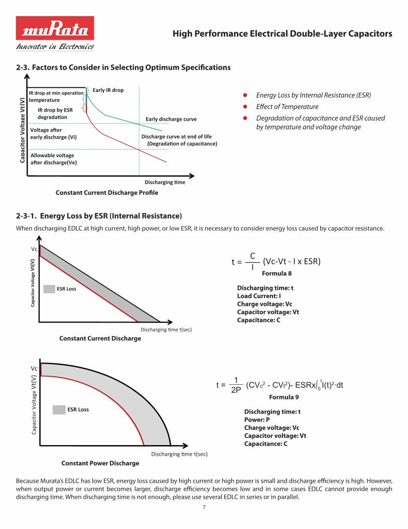
2-3-1. Energy Loss by ESR (Internal Resistance)When discharging EDLC at high current, high power, or low ESR, it is necessary to consider energy loss caused by capacitor resistance.
Because Murata’s EDLC has low ESR, energy loss caused by high current or high power is small and discharge efficiency is high. However, when output power or current becomes larger, discharge efficiency becomes low and in some cases EDLC cannot provide enough discharging time. When discharging time is not enough, please use several EDLC in series or in parallel.
Constant Current Discharge Profile
Capa
cito
r Vol
tage
Vt(
V)
Discharging time
Early discharge curve
Discharge curve at end of life
Early IR dropIR drop at min operation temperature
IR drop by ESR degradation
(Degradation of capacitance)
Allowable voltage after discharge(Ve)
Voltage after early discharge (Vi)
Constant Current Discharge
Capa
cito
r Vol
tage
Vt(
V)
Discharging time t(sec)
ESR Loss
Vc
Discharging time: tLoad Current: ICharge voltage: VcCapacitor voltage: VtCapacitance: C
Formula 8
(Vc-Vt - I x ESR)CI t =
Constant Power Discharge
Capa
cito
r Volta
ge V
t(V)
Discharging time t(sec)
ESR Loss
Vc
Discharging time: tPower: PCharge voltage: VcCapacitor voltage: VtCapacitance: C
Formula 9
t = (CVc2 - CVt2)- ESRx∫0
tI(t)2·dt1
2P

High Performance Electrical Double-Layer Capacitors
8
Discharge Efficiency from 5.5V to2.0V
2-3-2. Effect of Temperature ESR of EDLC depends on temperature. When temperature becomes low, ESR becomes high. Therefore, when using EDLC at low temperature, discharge efficiency becomes low. Although Murata’s EDLC is designed to provide stable output throughout a wide range of temperatures, consider energy loss by ESR increase if needed.
Discharge efficiency data (DMF series, rated voltage 5.5V, nominal capacitance 350mF, ESR60mΩ)
Charge condition: 5.5V 30min
Discharge efficiency from 5.5V to 2.0V is shown below in two patterns: Constant current discharge profile and constant power discharge profile.
Discharge efficiency at low temperature is lower than at room temperature.
Constant Current Discharge Profile (@25°C)
2.0
2.5
3.0
3.5
4.0
4.5
5.0
5.5
0 100 200 300
1A2A4A8A
Volt
age
(V)
Time (msec)
2.0
2.5
3.0
3.5
4.0
4.5
5.0
5.5
6.0
0 100 200 300
Volt
age
(V)
Time (msec)
1W5W10W20W
Constant Power Discharge Profile (@25°C)
Discharge efficiency (constant current discharge) Discharge efficiency (constant power discharge)
1A 2A 4A 8A 1W 5W 10W 20W
Charge (C) Q 1.21 1.16 1.08 0.93 Discharge Energy (J) E 4.58 4.22 3.82 3.11
Discharge efficiency (%) Q/Q0 99 95 88 76 Discharge efficiency(%) E/E0 100 92 83 68Standard charge(Q0) calculation using nominal capacitance Standard charge energy (E0) calculation using nominal capacitanceQ0 = C(Vc – Vt) = 0.35 x (5.5 – 2.0) = 1.23(C) E0 = ½ x C(Vc2 – Vt2) = 0.5 x 0.35 x (5.52 – 2.02) = 4.59(J)Q = I(t5.5v – t2.0v) E = ½ x W(t5.5v – t2.0v)
ESR
Cha
nge
(%)
Temperature (°C)
-50
0
50
100
150
200
250
300
350
400
-40 -30 -20 -10 0 10 20 30 40 50 60 70 80
e.g. DMF series 350mF e.g. DMF series 350mF

High Performance Electrical Double-Layer Capacitors
9
2-3-3. Degradation of Capacitance and ESR Caused by Temperature and Voltage Change Generally speaking, when temperature drops 10 degrees, the life time of EDLC is doubled. EDLC has two degradation patterns. One is degradation of the electrochemical system (such as electrode or electrolyte caused by applying voltage) and the other is drying up by the evaporation of the electrolyte. In both cases, ESR increases and capacitance decreases. The final failure is open mode by increasing internal resistance. In order to use EDLC reliably over the long term, close attention must be paid to the operating temperature condition.
How much the voltage accelerates degradation is still not fully understood. It depends on voltage condition and environment of usage. For details, please contact your local Murata representative.
Constant current discharge Constant power discharge
1A 2A 4A 1W 5W 10W
Charge(C) Q
25°C 1.21 1.16 1.08 Discharge Energy(J) E
25°C 4.58 4.22 3.82
-30°C 1.01 0.83 0.55 -30°C 3.78 2.20 1.56
Discharge efficiency(%) Q/Q0
25°C 99 95 88 Discharge efficiency(%) E/E0
25°C 100 92 83
-30°C 83 68 45 -30°C 82 48 34Standard charge (Q0) calculation using nominal capacitance Standard charge energy (E0) calculation using nominal capacitanceQ0 = C(Vc – Vt) = 0.35 x (5.5 – 2.0) = 1.23(C) E0 = ½ x C(Vc2 – Vt2) = 0.5 x 0.35 x (5.52 – 2.02) = 4.59(J)Q = I(t5.5v – t2.0v) E = ½ x W(t5.5v – t2.0v)
Constant Current Discharge Profile
2.0
2.5
3.0
3.5
4.0
4.5
5.0
5.5
6.0
0 100 200 300
Vol
tage
(V)
Time (msec.)
25°C 1A
25°C 2A
25°C 4A
-30°C 1A
-30°C 2A
-30°C 4A
Constant Power Discharge Profile
2.0
2.5
3.0
3.5
4.0
4.5
5.0
5.5
6.0
0 100 200 300
25°C 1W
25°C 5W
25°C 10W
-30°C 1W
-30°C 5W
-30°C 10W
Vol
tage
(V)
Time (msec.)
e.g. DMF series 350mF e.g. DMF series 350mF

High Performance Electrical Double-Layer Capacitors
10
Example (DMF Series):
Degradation of Capacitance and ESR
Load: DC4.2V@70°C
For example, according to the above graph, the capacitance drops to 15% at 1000hrs. The time the capacitance drops to 15% under the condition of 4.2V, 40°C is calculated by the following formula: 1,000 hrs x 2(70-40/10) = 8,000 hrs.
ESR Capacitance
ESR
chan
ge (%
)
Time (hr)
0
10
20
30
40
50
60
70
80
90
100
0 100 200 300 400 500 600 700 800 900 1000
Capa
cita
nce
chan
ge (%
)
Time (hr)
-50
-40
-30
-20
-10
0
0 100 200 300 400 500 600 700 800 900 1000

High Performance Electrical Double-Layer Capacitors
11
If you would like to provide the information requested for the conditions below, Murata can make more detailed proposals based on customer-specific applications.
Discharge Condition of Capacitor
Discharging
Discharge ConditionEDLC voltage
1. Max charge voltage VMax
2. Allowable Min.voltage Vmin
t
Required charge(C) or Energy(J)*Energy(J) = Power(W) x Discharging time t(sec)*Charge(C) = Current(A) x Discharging time t(sec)
time
Early voltage characteristic
Condition Example of Customer Condition Purpose
Charge condition
Charge voltage for capacitor Charge voltage Vmax 2.5V To confirm required number of cells in
series and consider discharge time.Charge current (in case of constant current charge) 500mA
Discharge condition
Charge(Q) or Energy(J) 150mJ or 300mC To confirm required current.Power × time(W x sec) or Current × time(A × sec) Numbers of discharge on a single charge
1.5W×100msec or 3A×100msec Numbers of discharge on a single charge (5 times)
Regarding discharge effectiveness, it is necessary to consider max power or current because it is affected by energy loss caused by internal resistance.
Accepted lower limit of voltage Vmin 1.3(V) To calculate the discharging time.
Minimum operation temperature -20°CAt low temperature, discharge effectiveness decreases because of ESR increase.
Discharge profile
Usage environment Actual usage temperature profile
Under 40°C (typ) 30,000hrs 70°C (Max) Under 500hrs
To confirm capacitance decrease and ESR increase throughout the product life.
Others Loss on the circuit Effectiveness (%)or Resistance (Ω) To confirm required capacitance.

High Performance Electrical Double-Layer Capacitors
12
3. Cautions for Use 3-1. VoltagezzResistance Voltage of EDLC
By using an organic electrolyte, Murata’s EDLC provides high voltage. However, applying a higher voltage than rated voltage on EDLC may cause degradation. Please ensure not to apply excessive voltage on EDLC.
When using several EDLCs in series, voltage may become unbalanced and excessive voltage may be applied. Therefore, consider applying enough voltage margin and balance control.
zzSeries/Parallel Use
Use several capacitors in series according to required voltage. When discharging time needs to be increased, use several capacitors in parallel.
zzVoltage Balance
When using capacitors in series, use balance resistance in parallel to the capacitor or use an active balance circuit. For more details, see Murata’s spec sheet.
If there are temperature gaps between capacitors, voltage will lose balance. Ensure that there is no temperature gap between capacitors.
zzPolarity
Verify the orientation of EDLC before use in accordance with the markings of polarity on the products. In principle, EDLC has no polarity. However, EDLC cannot be used under AC. Using EDLC under AC condition may cause degradation and leakage.
3-2. Self HeatingPlease use EDLC under ensured temperature considering self heating of a capacitor. Please see our specification sheet for further details.
3-3. Mounting ConditionsMurata’s EDLC product is non-reflowable due to the internal chemical system. For mounting, use a soldering iron or special connector. See our spec sheet for recommended soldering.
3-4. Storage ConditionsPlease avoid storage at high temperature or high humidity. Please see our catalog or specification sheet for further details.

High Performance Electrical Double-Layer Capacitors
13
4. Product Lineup Detail4-1. Product Lineup
4-2. Part Number Description
DMF 3R 5R5 L 334 M 3D T A0➀ ➁ ➂ ➃ ➄ ➅ ➆ ➇ ➈
1. Series
DMT High Reliability Type
DMF High Peak Power Type
2. External Dimension (L×W×T) (mm)
Code L W T
33 21.0±0.5 14.0±0.5 3.5±0.2
3Z 21.0±0.5 14.0±0.5 3.2±0.2
3. Rated Voltage (DC) Expressed by three-digit alphanumerics
Code Rated Voltage
4R2 4.2V (constant)
5R5 5.5V (peak) / 4.2V (constant)
4. ESR
Code ESR @1kHz
H 45mΩ
S 130mΩ
5. Nominal Capacitance
Code Nominal Capacitance
474 47x104µF = 470mF
6. Capacitance Tolerance
Code Tolerance
M ±20%
7. External Terminal
Code Terminal Specification
3D 3 Terminals (+ / – / Balance)
8. Packing Code
Code Packing Specification
T Tray Type, 50pcs/Tray
9. Inhouse Specification Code Expressed by two-digit alphanumerics
Series Murata Part Number Rated Voltage (V)
Capacitance (mF)
ESR@1kHz (mΩ) LxW (mm) Thickness
(mm)Operating
Temperature
DMT Series (High reliability type) DMT334R2S474M3DTA0 4.2
470
130
14 x 21
3.5Min: -30°C
Max: +85°C 70° 5 years
DMF Series (High peak power type) DMF3Z5R5H474M3DTA0 4.2 (constant)
5.5 (max peak) 45 3.2 Min: -30°C Max: +70°C
-
+
B

High Performance Electrical Double-Layer Capacitors
14
4-5. Marking
4-3. Dimensions (mm) 4-4. Land Pattern Design
Positive Electrode
Rated Voltage
ESR Code
Capacitance and Tolerance Code
Negative Electrode
Series Code
Balance Electrode
Sequence Number
-
+
B
DMF H474M 5.5Vp
* * ** *
14.0 ±0.5mm
25.5mm Max (typ: 25.0)
21.0 ±0.5mm
s: Less than 0.2mm
4.8mm Max (typ: 4.3mm)
T
a=2.5mmb=3.0~4.0mmc=1.0mmd=3.5mmf =3.5mmLand pattern
Land pattern and Product package
Productpackage
Balance Terminal a a a
c c
b
d
f
Negative (–) Terminal Positive (+) Terminal

www.murataamericas.com/edlc
Head Office 1-10-1, Higashi Kotari 1-chomeNagaokakyo-shi, Kyoto617-8555, JapanPhone: 81-75-951-9111
International Division 3-29-12, Shibuya 3-chome,Shibuya-ku, Tokyo150-0002 JapanPhone: 81-3-5469-6123
Murata AmericasMurata Electronics N.A., Inc. (Regional HQ)2200 Lake Park DriveSmyrna, GA 30080-7604, USA.Phone: 1-770-436-1300Fax: 1-770-436-3030
For additional information visit:www.murataamericas.com/edlc
Murata (China) Investment Co., Ltd.Lane 318 Yonghe RoadZhabei District, Shanghai 200072, ChinaPhone: 86-21-3205-4616Fax: 86-21-3205-4617
Murata EuropeMurata Electronics Europe B.V. (Regional HQ)Daalmeerstraat 4, 2131HC HoofddorpThe NetherlandsPhone: +31-(0)23-5698360Fax: +31-(0)23-5698361
Taiwan Murata Electronics Co., Ltd.No 225 Chung - Chin Road, Taichung, TaiwanPhone: 886-4-2425-4151
Murata Electronics Singapore (Pte.) Ltd.200 Yishun Avenue 7Singapore, 768927Tel: 65-6758-4233Fax: 65-6758-2026
© September 2013 Murata Americas