Embed Size (px)
Citation preview
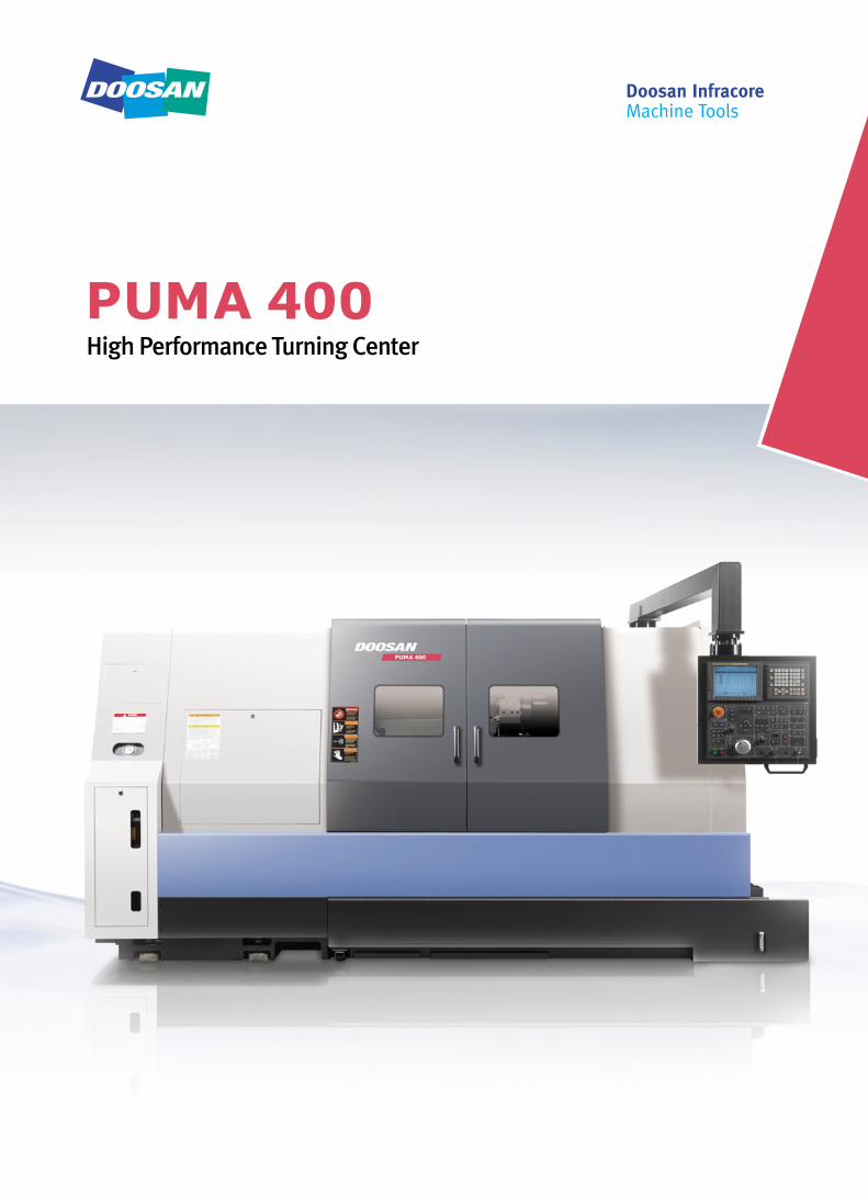
High Performance Turning Center
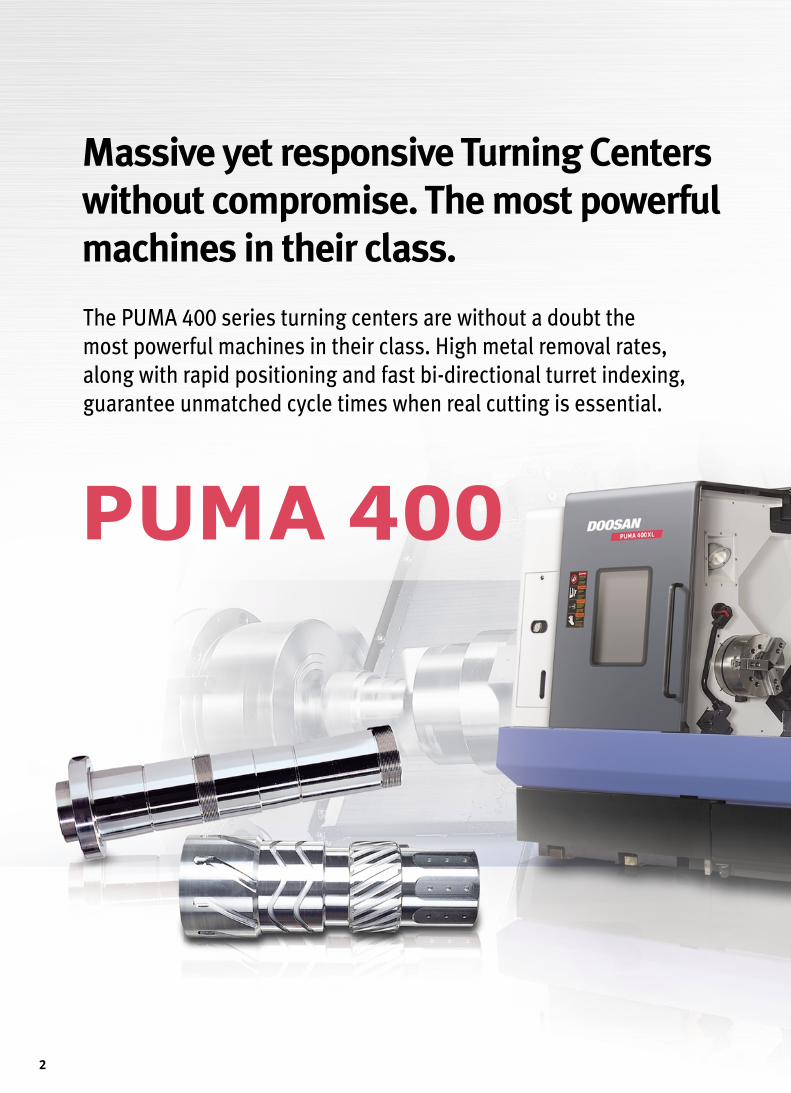
The PUMA 400 series turning centers are without a doubt the
most powerful machines in their class. High metal removal rates,
along with rapid positioning and fast bi-directional turret indexing,
guarantee unmatched cycle times when real cutting is essential.
Massive yet responsive Turning Centers
without compromise. The most powerful
machines in their class.
2
3
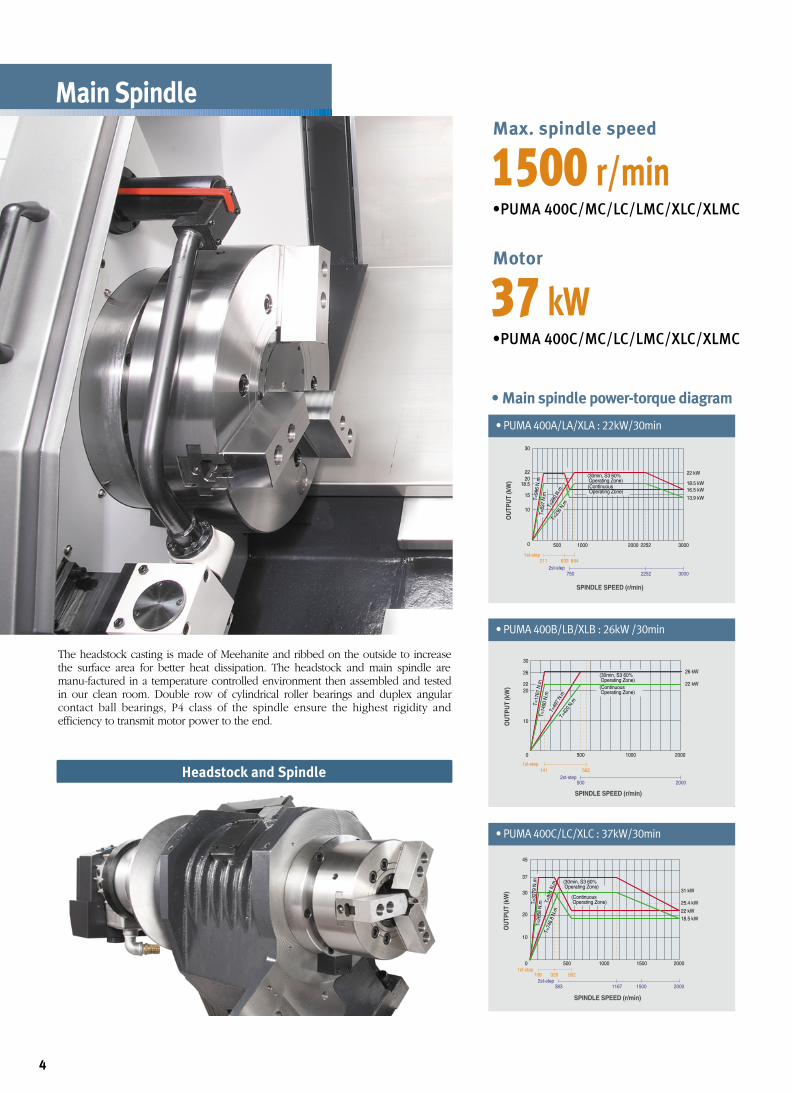
Main Spindle
30
2220
22 kW
18.5 kW16.5 kW
13.9 kW
18.5
15
10
0 500
1st-step211 633 844
2st-step750 2252 3000
1000 2000 2252 3000
OU
TPU
T (k
W)
SPINDLE SPEED (r/min)
T=99
6 N
.mT=
837
N.m
T=28
0 N.
mT=
236
N.m
(30min, S3 60% Operating Zone)(Continuous Operating Zone)
• PUMA 400A/LA/XLA : 22kW/30min
141 562
22 kW
26 kW
30
26
2220
10
0 500 1000 2000
1st-step
500 20002st-step
OU
TPU
T (k
W)
SPINDLE SPEED (r/min)
T=17
61 N
.mT=
1490
N.m
T=49
7 N.
mT=
420
N.m
(30min, S3 60% Operating Zone)(Continuous Operating Zone)
• PUMA 400B/LB/XLB : 26kW /30min
108 328 562
383 1167 1500 2000
18.5 kW22 kW
25.4 kW
31 kW30
37
45
20
10
0 500 1000 1500 20001st-step
2st-step
OU
TPU
T (k
W)
SPINDLE SPEED (r/min)
T=32
79 N
.mT=
2658
N.m T=
921
N.m
T=74
6.8
N.m
(30min, S3 60% Operating Zone)
(Continuous Operating Zone)
• PUMA 400C/LC/XLC : 37kW/30min
Max. spindle speed
•PUMA 400C/MC/LC/LMC/XLC/XLMC
1500 r/min
Motor
•PUMA 400C/MC/LC/LMC/XLC/XLMC
37 kW
The headstock casting is made of Meehanite and ribbed on the outside to increasethe surface area for better heat dissipation. The headstock and main spindle aremanu-factured in a temperature controlled environment then assembled and testedin our clean room. Double row of cylindrical roller bearings and duplex angularcontact ball bearings, P4 class of the spindle ensure the highest rigidity andefficiency to transmit motor power to the end.
Headstock and Spindle
• Main spindle power-torque diagram
4
ø10
2
ø10
0
ø91
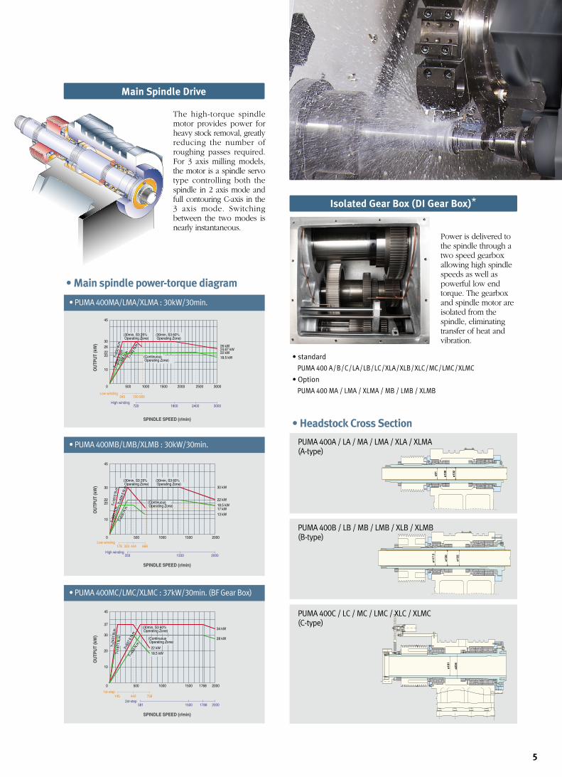
The high-torque spindlemotor provides power forheavy stock removal, greatlyreducing the number ofroughing passes required.For 3 axis milling models,the motor is a spindle servotype controlling both thespindle in 2 axis mode andfull contouring C-axis in the3 axis mode. Switchingbetween the two modes isnearly instantaneous.
Main Spindle Drive
45
30
2622
26 kW24.67 kW22 kW18.5 kW20
10
0 500 1000 1500 2000 2500 3000
Low winding345
High winding720 1800 2400 3000
720 900
OU
TPU
T (k
W)
SPINDLE SPEED (r/min)
T=83
0 N
.mT=
608.
6 N
.mT=
398
N.m
T=29
2 N.
m
(Continuous Operating Zone)
(30min, S3 25% Operating Zone)
(30min, S3 60% Operating Zone)
• PUMA 400MA/LMA/XLMA : 30kW/30min.
45
30
22 22 kW
30 kW
18.5 kW17 kW13 kW
20
10
0 500 1000 1500 2000Low winding
178 333 444 668
High winding333 1333 2000
OU
TPU
T (k
W)
SPINDLE SPEED (r/min)
T=63
0 N.
m
T=99
3 N
.mT=
1610
N.m
T=85
9.5
N.m
(Continuous Operating Zone)
(30min, S3 25% Operating Zone)
(30min, S3 60% Operating Zone)
• PUMA 400MB/LMB/XLMB : 30kW/30min.
45
37
3028 kW
34 kW
22 kW18.5 kW
20
10
0 500 1000 1500 1768 2000
1st-step145 442 758
2st-step581 1500 1768 2000
OU
TPU
T (k
W)
SPINDLE SPEED (r/min)
T=49
3 N.
m
T=60
7.6
N.m
T=19
71 N
.m
T=24
31 N
.m
(Continuous Operating Zone)
(30min, S3 60% Operating Zone)
• PUMA 400MC/LMC/XLMC : 37kW/30min. (BF Gear Box)
• Main spindle power-torque diagram
PUMA 400A / LA / MA / LMA / XLA / XLMA (A-type)
ø11
7.5
ø13
0
ø13
2
PUMA 400B / LB / MB / LMB / XLB / XLMB(B-type)
ø18
1
ø23
6
PUMA 400C / LC / MC / LMC / XLC / XLMC (C-type)
• Headstock Cross Section
5
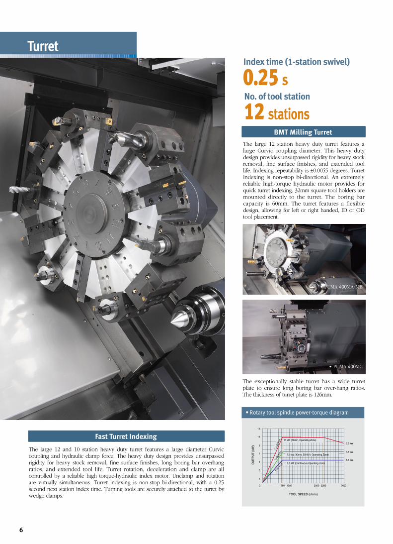
Isolated Gear Box (DI Gear Box)*
Power is delivered tothe spindle through atwo speed gearboxallowing high spindlespeeds as well aspowerful low endtorque. The gearboxand spindle motor areisolated from thespindle, eliminatingtransfer of heat andvibration.
• standard
PUMA 400 A/B/C/LA/LB/LC/XLA/XLB/XLC/MC/LMC/XLMC
• Option
PUMA 400 MA / LMA / XLMA / MB / LMB / XLMB
• Rotary tool spindle power-torque diagram
0.25 sIndex time (1-station swivel)
12 stations
No. of tool station
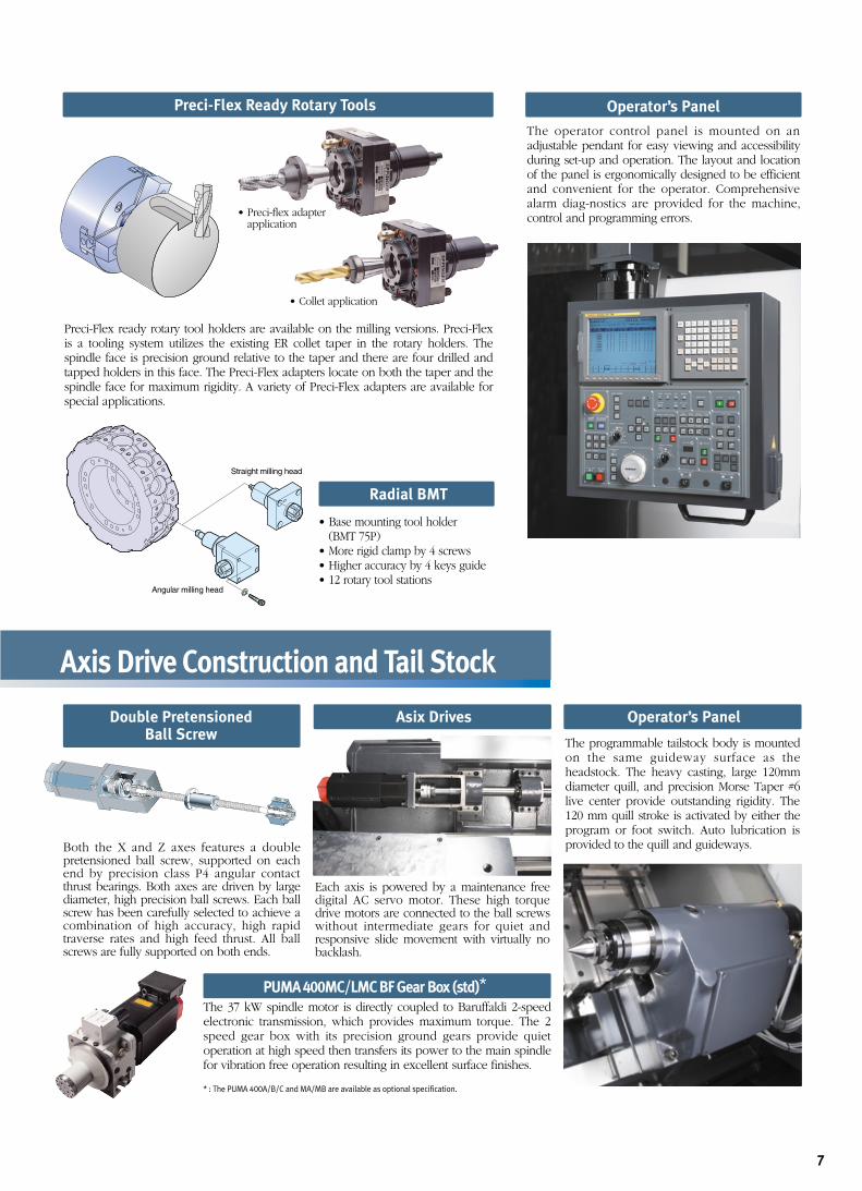
The large 12 and 10 station heavy duty turret features a large diameter Curviccoupling and hydraulic clamp force. The heavy duty design provides unsurpassedrigidity for heavy stock removal, fine surface finishes, long boring bar overhangratios, and extended tool life. Turret rotation, deceleration and clamp are allcontrolled by a reliable high torque-hydraulic index motor. Unclamp and rotationare virtually simultaneous. Turret indexing is non-stop bi-directional, with a 0.25second next station index time. Turning tools are securely attached to the turret bywedge clamps.
The large 12 station heavy duty turret features alarge Curvic coupling diameter. This heavy dutydesign provides unsurpassed rigidity for heavy stockremoval, fine surface finishes, and extended toollife. Indexing repeatability is ±0.0055 degrees. Turretindexing is non-stop bi-directional. An extremelyreliable high-torque hydraulic motor provides forquick turret indexing. 32mm square tool holders aremounted directly to the turret. The boring barcapacity is 60mm. The turret features a flexibledesign, allowing for left or right handed, ID or ODtool placement.
Turret
BMT Milling Turret
Fast Turret Indexing
6
• PUMA 400MA/MB
• PUMA 400MC
The exceptionally stable turret has a wide turretplate to ensure long boring bar over-hang ratios.The thickness of turret plate is 126mm.
9.5 kW
7.5 kW
5.5 kW
0
1
3
5
7
9
11
13
750 1000 2000 2250 3000
OU
TPU
T (k
W)
TOOL SPEED (r/min)
T=14
0 N
.mT=
95 N
.m
T=70
N.m
5.5 kW (Continuous Operating Zone)
7.5 kW (30min, S3 60% Operating Zone)
11 kW (10min, Operating Zone)
Preci-Flex Ready Rotary Tools
Radial BMT
Operator’s Panel
The operator control panel is mounted on anadjustable pendant for easy viewing and accessibilityduring set-up and operation. The layout and locationof the panel is ergonomically designed to be efficientand convenient for the operator. Comprehensivealarm diag-nostics are provided for the machine,control and programming errors.
Operator’s Panel
The programmable tailstock body is mountedon the same guideway surface as theheadstock. The heavy casting, large 120mmdiameter quill, and precision Morse Taper #6live center provide outstanding rigidity. The120 mm quill stroke is activated by either theprogram or foot switch. Auto lubrication isprovided to the quill and guideways.
Asix Drives
Each axis is powered by a maintenance freedigital AC servo motor. These high torquedrive motors are connected to the ball screwswithout intermediate gears for quiet andresponsive slide movement with virtually nobacklash.
7
Preci-Flex ready rotary tool holders are available on the milling versions. Preci-Flexis a tooling system utilizes the existing ER collet taper in the rotary holders. Thespindle face is precision ground relative to the taper and there are four drilled andtapped holders in this face. The Preci-Flex adapters locate on both the taper and thespindle face for maximum rigidity. A variety of Preci-Flex adapters are available forspecial applications.
Angular milling head
Straight milling head
• Base mounting tool holder(BMT 75P)
• More rigid clamp by 4 screws• Higher accuracy by 4 keys guide• 12 rotary tool stations
• Collet application
• Preci-flex adapter application
PUMA 400MC/LMC BF Gear Box (std)*
* : The PUMA 400A/B/C and MA/MB are available as optional specification.
Double Pretensioned Ball Screw
Both the X and Z axes features a doublepretensioned ball screw, supported on eachend by precision class P4 angular contactthrust bearings. Both axes are driven by largediameter, high precision ball screws. Each ballscrew has been carefully selected to achieve acombination of high accuracy, high rapidtraverse rates and high feed thrust. All ballscrews are fully supported on both ends.
The 37 kW spindle motor is directly coupled to Baruffaldi 2-speedelectronic transmission, which provides maximum torque. The 2speed gear box with its precision ground gears provide quietoperation at high speed then transfers its power to the main spindlefor vibration free operation resulting in excellent surface finishes.
Axis Drive Construction and Tail Stock
Bed and Way Construction
Rapid Traverse
• Scraping of surface • Outstanding rigidity for high feedrates
16 m/min
X-axis
20 (18)m/min
Z-axis
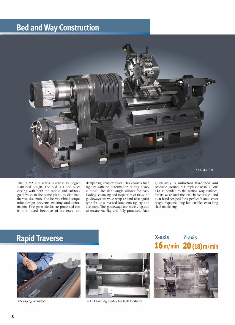
The PUMA 400 series is a true 45 degreeslant bed design. The bed is a one piececasting with both the saddle and tailstockguideways in the same plane to eliminatethermal distortion. The heavily ribbed torquetube design prevents twisting and defor-mation. Fine grain Meehanite processed castiron is used because of its excellent
dampening characteristics. This ensures highrigidity with no deformation during heavycutting. The slant angle allows for easyloading, changing and inspection of tools. Allguideways are wide wrap-around rectangulartype for un-surpassed long-term rigidity andaccuracy. The guideways are widely spacedto ensure stability and fully protected. Each
guide-way is induction hardened andprecision ground. A fluroplastic resin, Rulon®
142, is bonded to the mating way surfaces,for its wear and friction characteristics andthen hand scraped for a perfect fit and centerheight. Optional long bed enables extra-longshaft machining.
8
• PUMA 400
9
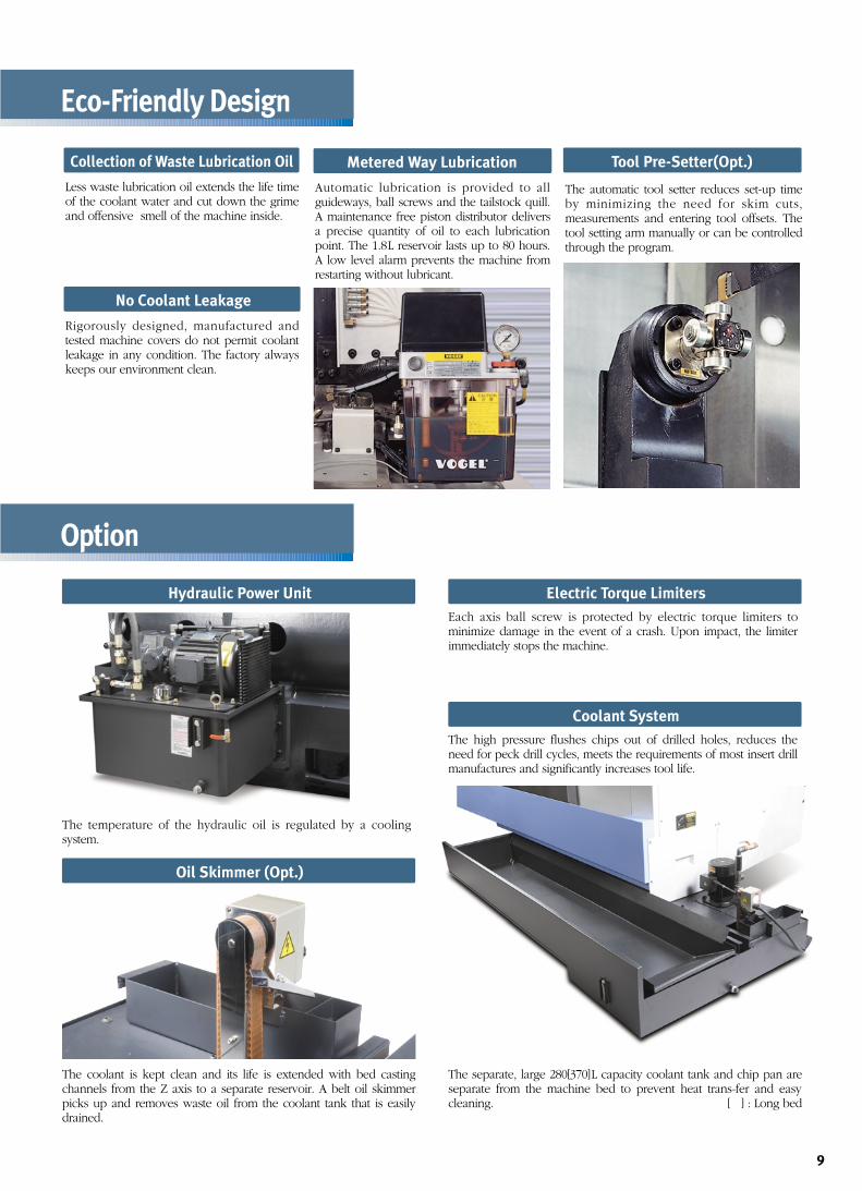
The coolant is kept clean and its life is extended with bed castingchannels from the Z axis to a separate reservoir. A belt oil skimmerpicks up and removes waste oil from the coolant tank that is easilydrained.
The high pressure flushes chips out of drilled holes, reduces theneed for peck drill cycles, meets the requirements of most insert drillmanufactures and significantly increases tool life.
The temperature of the hydraulic oil is regulated by a coolingsystem.
The separate, large 280[370]L capacity coolant tank and chip pan areseparate from the machine bed to prevent heat trans-fer and easycleaning. [ ] : Long bed
Eco-Friendly Design
Option
Hydraulic Power Unit
Oil Skimmer (Opt.)
Tool Pre-Setter(Opt.)
Coolant System
The automatic tool setter reduces set-up timeby minimizing the need for skim cuts,measurements and entering tool offsets. Thetool setting arm manually or can be controlledthrough the program.
Each axis ball screw is protected by electric torque limiters tominimize damage in the event of a crash. Upon impact, the limiterimmediately stops the machine.
Electric Torque Limiters
Collection of Waste Lubrication Oil
Less waste lubrication oil extends the life timeof the coolant water and cut down the grimeand offensive smell of the machine inside.
Metered Way Lubrication
Automatic lubrication is provided to allguideways, ball screws and the tailstock quill.A maintenance free piston distributor deliversa precise quantity of oil to each lubricationpoint. The 1.8L reservoir lasts up to 80 hours.A low level alarm prevents the machine fromrestarting without lubricant.
No Coolant Leakage
Rigorously designed, manufactured andtested machine covers do not permit coolantleakage in any condition. The factory alwayskeeps our environment clean.
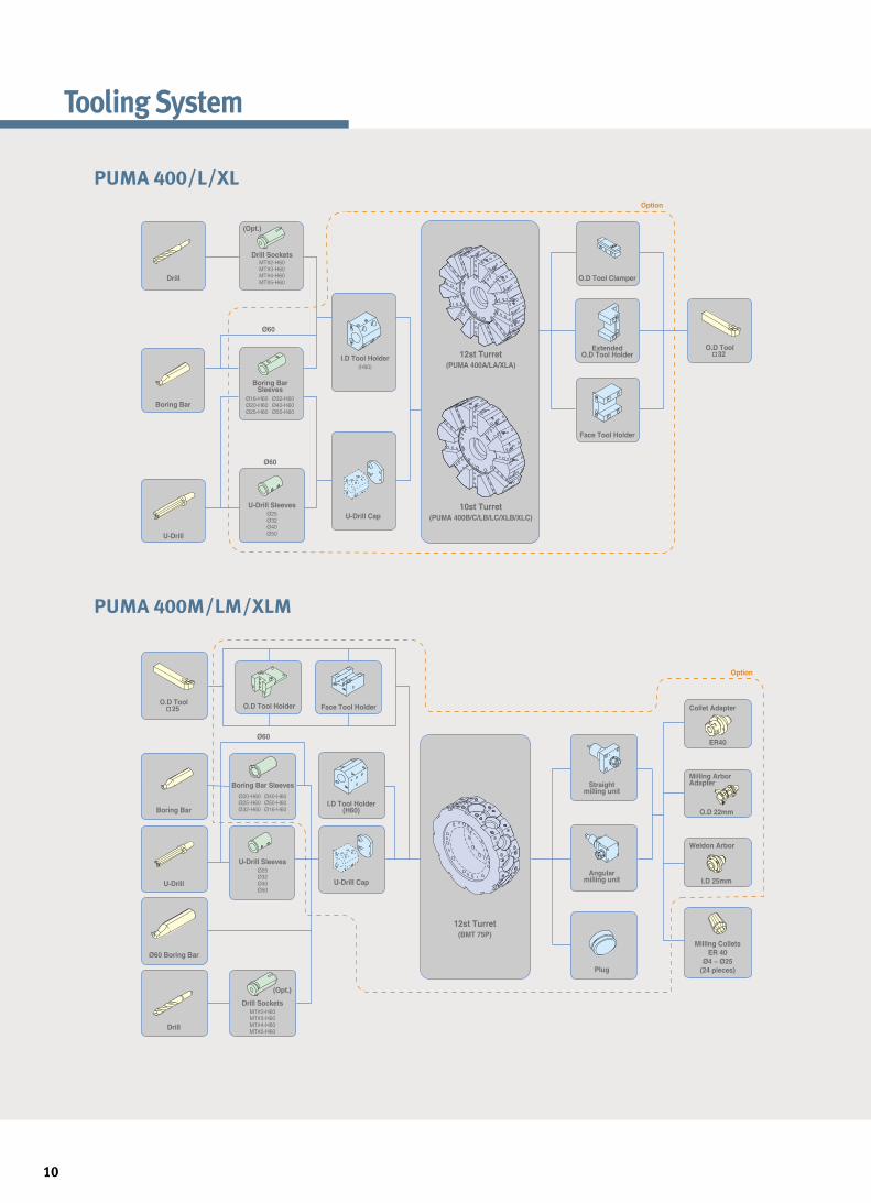
Tooling System
10
Drill
U-Drill
Drill Sockets
(Opt.)
Boring BarSleeves
Ø60
Boring Bar
Ø60
MT#2-H60MT#3-H60MT#4-H60MT#5-H60
U-Drill Sleeves
U-Drill Cap10st Turret
(PUMA 400B/C/LB/LC/XLB/XLC)
12st Turret(BMT 75P)
12st Turret(PUMA 400A/LA/XLA)
Ø25Ø32Ø40Ø50
Ø20-H60Ø25-H60Ø32-H60
Ø40-H60Ø50-H60Ø16-H60
I.D Tool Holder(H60)
O.D Tool Clamper
ExtendedO.D Tool Holder
O.D Tool 32
Face Tool Holder
Collet Adapter
Option
Option
Milling ArborAdapter
Weldon Arbor
Milling ColletsER 40
Ø4 ~ Ø25(24 pieces)
O.D 22mm
I.D 25mm
ER40
Straightmilling unit
Angularmilling unit
Plug
I.D Tool Holder(H60)
U-Drill Cap
Face Tool HolderO.D Tool Holder
Ø60
Boring Bar Sleeves
Ø16-H60Ø20-H60Ø25-H60
Ø32-H60Ø40-H60Ø50-H60
O.D Tool 25
U-Drill
Boring Bar
Ø60 Boring Bar
Drill
U-Drill SleevesØ25Ø32Ø40Ø50
Drill Sockets
(Opt.)
MT#2-H60MT#3-H60MT#4-H60MT#5-H60
PUMA 400/L/XL
PUMA 400M/LM/XLM
11
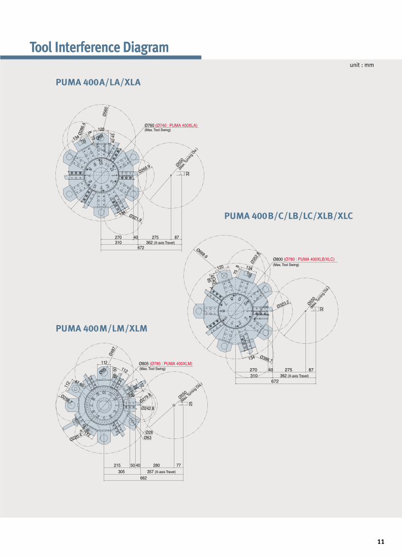
unit : mm
Tool Interference Diagram
Ø805 (Ø785 : PUMA 400XLM)
Ø800 (Ø780 : PUMA 400XLB/XLC)
Ø760 (Ø740 : PUMA 400XLA)
270 40 275310 362 (X-axis Travel)
672
215 50 40 280305 357 (X-axis Travel)
662
Ø63
150
112
112
Ø60
6050
25
750
112
Ø48
7
Ø35
2.8
Ø323.2
Ø386.7134
120 134
857
4540
708
Ø668.9
47 60
Ø258.7
112Ø220.4
11226
Ø242.8
Ø279.8
Ø26
77
87
(Max. Tool Swing)
(Max. Tool Swing)
(Max. Tool Swing)
(Max
. Tur
ning D
ia.)
120
134
Ø28
6.4
Ø56
0
870
4045
32
Ø550
(Max
. Turni
ng D
ia.)
Ø550
Ø260.9
Ø321.9134
Ø60
(Max
. Tur
ning D
ia.)
Ø550
32
270 40 275 87310 362 (X-axis Travel)
672
PUMA 400A/LA/XLA
PUMA 400B/C/LB/LC/XLB/XLC
PUMA 400M/LM/XLM
unit : mm
unit : mm
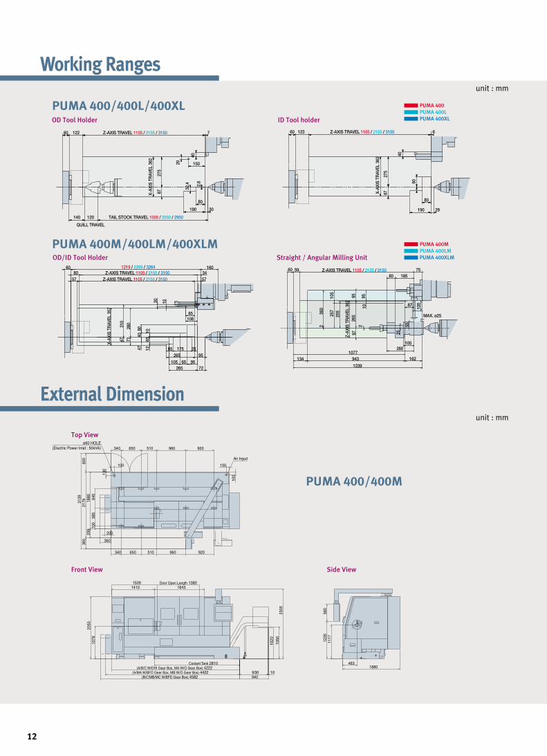
Working Ranges
12
External Dimension
OD Tool Holder ID Tool holder
OD/ID Tool Holder Straight / Angular Milling Unit
PUMA 400
PUMA 400L
PUMA 400XL
PUMA 400M
PUMA 400LM
PUMA 400XLM
1219 / 2269 / 3264 160Z-AXIS TRAVEL 1105 / 2155 / 3150
QUILL TRAVEL
TAIL STOCK TRAVEL 1000 / 2050 / 2950140
60 60 6123 Z-AXIS TRAVEL 1105 / 2155 / 3150122 Z-AXIS TRAVEL 1105 / 2155 / 3150
X-AX
IS T
RAV
EL 3
62
X-AX
IS T
RAV
EL 3
62
8727
5
8727
5
20
40 40
90
80
190 29
32.4
150
80
190 30
2.6
7
120
Z-AXIS TRAVEL 1105 / 2155 / 3150
Z-AX
IS T
RAV
EL 3
62
Z-AXIS TRAVEL 1105 / 2155 / 3150
20 10
10885
X-AX
IS T
RAV
EL 3
57
4731
0
7728
0
4740
80
1265
10
722659565105
265 952517565
6080 34
57 57
1095
87
260105
265
9795
2
25
55
100
75596018580
1077162943134
1239
255
105
257360
2MAX. ø25
2305
(A/B/C W/DHI Gear Box, MA W/O Gear Box) 4222463
1880
1117
1235
560
1079
2050
1410 1643
360
2179
600
3139
299
1880
340 650 510 960 920
340 650 510 960 920
1509 Door Open Length 1380
100
130
ø60 HOLE(Electric Power Inlet : 50kVA)
Air Input
100
100
Coolant Tank 2810
1050
200
360
(A/MA W/BFD Gear Box, MB W/O Gear Box) 4422(B/C/MB/MC W/BFD Gear Box) 4582
100
585
645
940
1020
930 10
PUMA 400/400L/400XL
PUMA 400/400M
PUMA 400M/400LM/400XLM
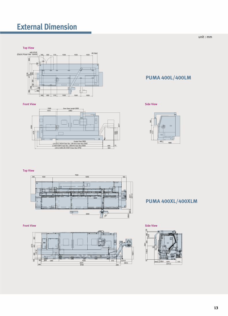
unit : mm
External Dimension
13
2317
1079
2050
4631880
1117
1235
560
360
2179
600
3139
299
1880
100
585
645
340 650 510 1000 1000 1000
340 650 510 1000 1000 1000
1410 24631509 Door Open Length 2200
100
130
ø60 HOLE(Electric Power Inlet : 50kVA)
Air Input
Coolant Tank 3930
1050
(LA/LB/LC W/DHI Gear Box, LMA W/O Gear Box) 5342(LA/MA W/BFD Gear Box, LMB W/O Gear Box) 5542
(LB/LC/LMB/LMC W/BFD Gear Box) 5702
200
360
940930 10
1020
2200
3200
105˚
1250 5055 3503457000
2017
294.
565
6.5
2311
.5
100
680
603
822
65 200 4235 61012606370
3306700949.5
1021
.1
2270
1127
.4
1279.5
280
14027
620
49.848
550
1136
.210
2351
294.9 135.6 1370 5102310.5
PUMA 400XL/400XLM
PUMA 400L/400LM
14
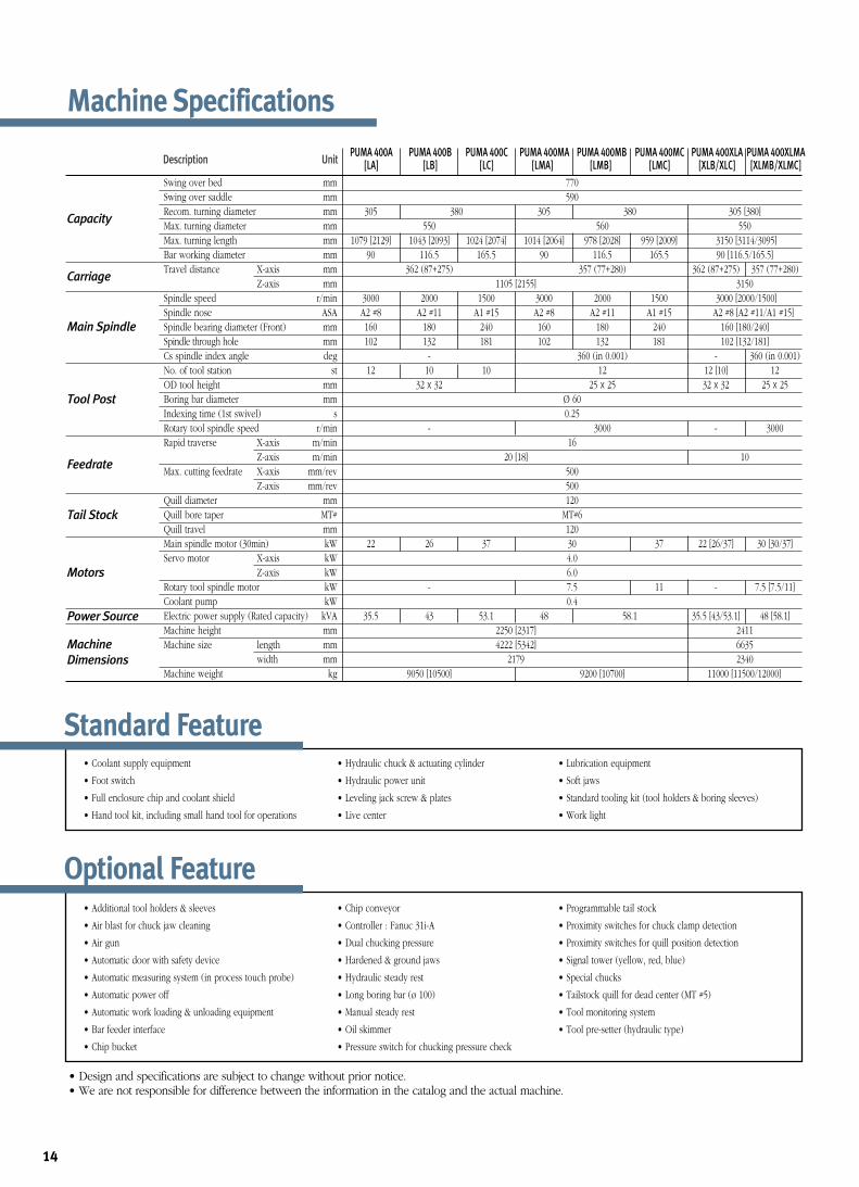
Swing over bed mmSwing over saddle mmRecom. turning diameter mmMax. turning diameter mmMax. turning length mmBar working diameter mmTravel distance X-axis mm
Z-axis mmSpindle speed r/minSpindle nose ASASpindle bearing diameter (Front) mmSpindle through hole mmCs spindle index angle degNo. of tool station stOD tool height mmBoring bar diameter mmIndexing time (1st swivel) sRotary tool spindle speed r/minRapid traverse X-axis m/min
Z-axis m/minMax. cutting feedrate X-axis mm/rev
Z-axis mm/revQuill diameter mmQuill bore taper MT#Quill travel mmMain spindle motor (30min) kWServo motor X-axis kW
Z-axis kWRotary tool spindle motor kWCoolant pump kWElectric power supply (Rated capacity) kVAMachine height mmMachine size length mm
width mmMachine weight kg
770590
305 380 305 380 305 [380]550 560 550
1079 [2129] 1043 [2093] 1024 [2074] 1014 [2064] 978 [2028] 959 [2009] 3150 [3114/3095]90 116.5 165.5 90 116.5 165.5 90 [116.5/165.5]
362 (87+275) 357 (77+280) 362 (87+275) 357 (77+280)1105 [2155] 3150
3000 2000 1500 3000 2000 1500 3000 [2000/1500]A2 #8 A2 #11 A1 #15 A2 #8 A2 #11 A1 #15 A2 #8 [A2 #11/A1 #15]160 180 240 160 180 240 160 [180/240]102 132 181 102 132 181 102 [132/181]
- 360 (in 0.001) - 360 (in 0.001)12 10 10 12 12 [10] 12
32 x 32 25 x 25 32 x 32 25 x 25Ø 600.25
- 3000 - 300016
20 [18] 10500500120
MT#6120
22 26 37 30 37 22 [26/37] 30 [30/37]4.0 6.0
- 7.5 11 - 7.5 [7.5/11]0.4
35.5 43 53.1 48 58.1 35.5 [43/53.1] 48 [58.1]2250 [2317] 24114222 [5342] 6635
2179 23409050 [10500] 9200 [10700] 11000 [11500/12000]
• Design and specifications are subject to change without prior notice.• We are not responsible for difference between the information in the catalog and the actual machine.
Capacity
Description UnitPUMA 400A PUMA 400B PUMA 400C PUMA 400MA PUMA 400MB PUMA 400MC PUMA 400XLA PUMA 400XLMA
[LA] [LB] [LC] [LMA] [LMB] [LMC] [XLB/XLC] [XLMB/XLMC]
Carriage
Main Spindle
Tool Post
Tail Stock
Feedrate
Motors
Power Source
Machine
Dimensions
Machine Specifications
Standard Feature• Coolant supply equipment
• Foot switch
• Full enclosure chip and coolant shield
• Hand tool kit, including small hand tool for operations
• Hydraulic chuck & actuating cylinder
• Hydraulic power unit
• Leveling jack screw & plates
• Live center
• Lubrication equipment
• Soft jaws
• Standard tooling kit (tool holders & boring sleeves)
• Work light
Optional Feature• Additional tool holders & sleeves
• Air blast for chuck jaw cleaning
• Air gun
• Automatic door with safety device
• Automatic measuring system (in process touch probe)
• Automatic power off
• Automatic work loading & unloading equipment
• Bar feeder interface
• Chip bucket
• Chip conveyor
• Controller : Fanuc 31i-A
• Dual chucking pressure
• Hardened & ground jaws
• Hydraulic steady rest
• Long boring bar (ø 100)
• Manual steady rest
• Oil skimmer
• Pressure switch for chucking pressure check
• Programmable tail stock
• Proximity switches for chuck clamp detection
• Proximity switches for quill position detection
• Signal tower (yellow, red, blue)
• Special chucks
• Tailstock quill for dead center (MT #5)
• Tool monitoring system
• Tool pre-setter (hydraulic type)
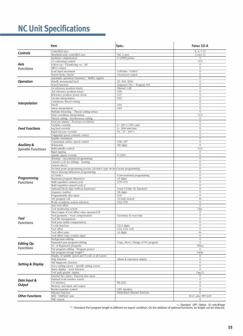
Controls
Axis
Functions
Operation
Interpolation
Feed Functions
Axuiliary &
Spindle Functions
Programming
Functions
Editing Op.
Functions
Setting & Display
Data Input &
Output
Tool
Functions
Other Functions
Item Spec. Fanuc 32i-A
Controlled axes X, Z, C (!)Simultaneously controlled axes Std. 2 axes 3 axes (!)Backlash compensation 0~±9999 pulsesCs contouring control (!)Follow-up / Chamfering on / offHRV2 controlLeast input increment 0.001mm / 0.0001"Stored stroke check1 Overtravel controlAutomatic operation (memory) / Buffer registerHandle incremental feed X1, X10, X100Search function Sequence NO. / Program NO.1st reference position return Manual, G282nd reference position return G30Reference position return check G27Circular interpolation G02Continuous thread cuttingDwell G04Linear interpolation G01Multiple threading / Thread cutting retractPolar coordinate interpolation (!)Thread cutting / Synchronous cuttingFeed per minute / Feed per revolutionFeedrate override 0 - 200 % (10% unit)Jog feed override 0 - 2000 mm/minRapid traverse override F0 / 25 / 100 %Tangential speed constant controlSpindle orientationConstantant surface speed control G96, G97M-function M3 digitsMulti-spindle control (!)Rigid tappingSpindle speed override 0~150%Absolute / Incremental programmingCanned cycle for drilling / Turning Custom macroDecimal point programming/pocket calculator type decimal point programmingDirect drawing dimension programmingeZ Guide i Conversational programmingMaximum program dimension ±9 digitsMulti repetitive canned cycle G70~G76Multi repetitive canned cycle 2Optional block skip (without hardware) Total 9 (Only NC function)Sequence number N8 digitsProgrammable data input G10Sub program call 10 folds nested 10Work coordinate system selection G52~G59Auto tool offsetTool monitoring system Opt.Direct input of tool offset value measured BTool geometry / wear compensation Geometry & wear dataTool life managementTool nose radius compensationT-code function T2+2 digitsTool offset G43, G44, G49Tool offset pairs ±6 digits 64Tool offset value counter inputBackground edittingExpanded part program editting Copy, Move, Change of NC programNo. of Registered programs 500eaPart program editing / Program protectPart program storage length*1 640mDisplay of spindle speed and T-code at all screenHelp function Alarm & Operation displaySelf diagnostic functionServo setting screen / Spindle setting screenStatus display / Lock function Tool path graphic display Opt.(!)External key input / External data inputExternal work number searchI/O interface RS-232CMemory card input and outputReader puncher control CH1 interfaceEthernet function Embedded ethernet functionMDI / DISPLAY unit 10.4" color TFT LCDPMC system
: Standard OPT : Option (!) : only M type *1 : Standard Part program length is different on export condition. On the addition of optional functions, its length can be reduced.
NC Unit Specifications
15

Design and specifications are subject to change without prior notice. EU1012SPi-ser
Sales & Support Network
ARGENTINA/Rosario AUSTRALIA/Melbourne/Sydney AUSTRIA/Vienna BELGIUM/Gullegem BRAZIL/Sao paulo BULGARIA/Sofia CANADA/Edmonton/Montreal/Toronto/Vancouver
CHILE/Santiago CHINA/Beijing/Chongqing/Guangzhou/Shanghai/Shenyang COLOMBIA/Bogota CZECH/Brno DENMARK/Randers EGYPT/Cairo FINLAND/Tampere FRANCE/Annecy
GERMANY/Dusseldorf GREECE/Athens HONG KONG/Kowloon HUNGARY/Budapest INDIA/Bangalore/Pune INDONESIA/Jakarta IRAN/Tehran ISRAEL/Herzlia ITALY/Parma
MALAYSIA/Kuala Lumpur/Penang/Johor Bahru MEXICO/Guadalajara /Mexico City /Monterrey /Vera Cruz NETHERLANDS/Goorn NEW ZEALAND/Auckland NORWAY/Oslo PAKISTAN
/Islamabad/Karachi/Lahore PHILIPPINES/Manila POLAND/Krakow PORTUGAL/Lisbon ROMANIA/Bucharest RUSSIA/Moscow SAUDI ARABIA/Riyadh SINGAPORE/Singapore
SLOVENIA/Ljubljana SOUTH AFRICA/Kempton Park SPAIN/Barcelona SWEDEN/Stockholm SWITZERLAND/Zurich TURKEY/Istanbul THAILAND/Bangkok U.A.E/Sharjah
U. K./Leamington U.S.A./Atlanta/Birmingham/Charlotte/Chicago/Cincinnati/Cleveland/Dallas/Denver/Detroit/Houston/Indianapolis/Kansas City/Little Rock/Los Angeles/Milwaukee/Minneapolis
/New Orleans/Norfolk/Philadelphia/Phoenix/Pittsburgh/Portland/Rochester/Salt Lake City/San Diego/San Francisco/Seattle/Springfield/St. Louis/Tampa/Trenton/Tulsa VENEZUELA/Valencia
VIETNAM/Hanoi/Ho Chi Minh City
Head Office : Doosan Tower 23rd FL., 18-12, Euljiro-6Ga, Jung-Gu, Seoul, Korea 100-730 Tel : ++82-2-3398-8693 / 8671 / 8680 Fax : ++82-2-3398-8699
Doosan Infracore America Corp.: 8 York Avenue, West Caldwell, NJ 07006, U.S.A. Tel : ++1-973-618-2500 Fax : ++1-973-618-2501
Doosan Infracore Germany GmbH : Hans-Böckler-Strasse 29, D-40764 Langenfeld-Fuhrkamp, Germany. Tel : ++49-2173-8509-0 Fax : ++49-2173-8509-60
Doosan Infracore Yantai Co., LTD : 13 Building, 140 Tianlin Road, Xuhui District, Shanghai, China (200233) Tel : ++86-21-6440-3384 (808, 805) Fax : ++86-21-6440-3389
http://www.doosaninfracore.com/machinetools


![[ For Oil Country Applications ] - Bulmakmetal Ltdbulmakmetal.com/wp-content/uploads/2016/10/LOC500_650-E-1-200Ja… · [ For Oil Country Applications ] ... clamp/unclamp operations](https://img.pdfslide.net/doc/110x75/5ad647337f8b9a5c638e213c/-for-oil-country-applications-bulmakmetal-for-oil-country-applications.jpg)


![HB06MA0012E - Maintenance Manual - Quick Turn Smart … · Select the [TURRET UNCLAMP] menu item in manual operation mode to unclamp the tu rret. Highlight the menu item. TAIL THRUST](https://img.pdfslide.net/doc/110x75/5ad647337f8b9a5c638e20e8/hb06ma0012e-maintenance-manual-quick-turn-smart-the-turret-unclamp-menu.jpg)