Embed Size (px)
Citation preview
High-power CO lasers in Russia
This article has been downloaded from IOPscience. Please scroll down to see the full text article.
1993 Quantum Electron. 23 93
(http://iopscience.iop.org/1063-7818/23/2/R03)
Download details:
IP Address: 128.250.144.144
The article was downloaded on 16/09/2013 at 11:43
Please note that terms and conditions apply.
View the table of contents for this issue, or go to the journal homepage for more
Home Search Collections Journals About Contact us My IOPscience
REVIEW
High-power CO lasers in Russia1'A. A. lonin
P. N. Lebedev Physics Institute, Russian Academy of Sciences, Moscow(Submitted May 28, 1992)Kvantovaya Elektron. (Moscow) 20, 113-122 (February 1993)
The research-and-development effort on CO lasers and applications of these lasers in Russiaare reviewed. Various types of cw, pulsed, and periodic-pulse CO lasers have beendeveloped in various laboratories. Sealed-oif, water-cooled cw CO lasers with an outputpower of 5-10 W, pumped by a self-sustained electric discharge, are being used successfully inthe manufacture of electronic devices and in medicine. The output power of fast-flowcryogenic cw CO lasers with a self-sustained discharge ranges up to ~ 1 kW. The use ofelectron-beam pumping has made it possible to develop pulsed electron-beam-sustained (BBS) CO lasers with an energy up to ~ 1 kJ and also to develop cw and periodic-pulse BBS CO lasers with a power of 10 kW and an efficiency up to ~40%. Researchon pulsed electron-beam-sustained CO lasers has been the scientific foundation for theconstruction of CO laser systems of the (master oscillator)-amplifier type and periodic-pulse CO lasers. A CO laser system with an output energy ~200 J and an output beamdivergence of 2 • 10~4 rad has been developed. Requirements on the effective gain inthe active medium and on the transport through atmospheric air of multifrequency outputpulses from CO laser with various spectral and temporal characteristics have beenformulated. A supersonic BBS CO laser with a peak power ~ 105 W and a 10-kW periodic-pulse BBS CO laser with subsonic flow have been developed. The latter laser generatespulses with an energy ~ 100 J and a repetition frequency up to 100 Hz. The BBS CO laserswith injection of the laser mixture in the liquid phase are discussed. Lasers usingnuclear ionization of the active medium are also discussed.
INTRODUCTION
Gas-discharge CO lasers1 (A~5/xm) have several spe-cific properties which distinguish them from other high-power IR lasers. They have a high lasing efficiency (~ 30-50%) and a large specific output energy, which is 2-2.5times that of CO2 lasers.2'3 The diffraction limit of theangular divergence of the beams from CO lasers is half thatof CO2 lasers. The self-effects of the light in the activemedium are less pronounced. Several of the optical mate-rials which are transparent at the output wavelength of aCO laser have a greater resistance to laser damage and agreater mechanical strength. There exist optical materialswhich are transparent in the 5-/im spectral region, fromwhich optical fibers with low optical losses can be fabri-cated. For many of the output wavelengths of CO lasersthere are "transparency windows" in the atmosphere, inwhich the absorption is lower by a large factor than thatfor the beams from CO2 lasers. Finally, it has recently beenshown that light with /l~5jum interacts more effectivelywith structural materials4'5 and human tissues.6
Research on CO lasers in the USSR began at the Leb-edev Physics Institute in Moscow in the late 1960s and theearly 1970s (Refs. 7-10, for example). The power level ofthe CO lasers which have been developed in Russia rangesfrom a few watts to several tens of kilowatts, depending onthe type of pumping, the cooling method, and the dimen-sions. The term "high-power" is generally applied to laserswith power levels above 1 kW, but this boundary is quite
arbitrary. In the present review we look at CO lasers withoutput power levels sufficient to have a strong influence onthe materials being processed. The numerous and ex-tremely interesting physical processes which occur in theactive media of CO lasers lie outside the scope of thisreview; the interested reader is referred to the by now clas-sic review32 by Sobolev and Sokovikov and also to some
16,33,34more recent reviews.
1. CARBON MONOXIDE LASERS PUMPED BY A SELF-SUSTAINED DISCHARGE
1.1. Sealed-off cw CO lasers
Research on the physics of CO lasers which was begunin the Lebedev Physics Institute7'9 and then pursued in theIstok Research and Production Association6 (in MoscowOblast) has resulted in the development of industrial in-stallations. Water-cooled, sealed-off CO lasers with powerlevels ranging from 2 W (the ILGN-705) to 75 W (theKasseta-4M) are presently available commercially inRussia.35 Most of the research on sealed-off CO lasers andon laser systems based on them is being carried out by theIstok Association. Lowering the temperature of the liquidcooling the wall of the laser cell from 27 °C to 1 °C doublesthe output power and increases the efficiency from 8.5 to18%.
These CO lasers have been used for technological op-erations in electronics and medicine. Carbon monoxide la-
93 Quantum Electron. 23 (2), February 1993 1063-7818/93/020093-09S10.00 © 1993 American Institute of Physics 93
3 Pln. kW
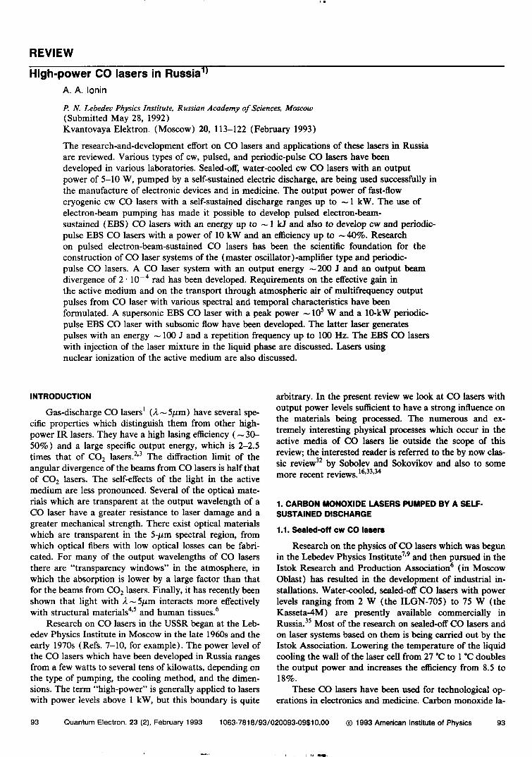
FIG. 1. Schematic diagrams of (a) a three-pass and (b) a multiple-beam,sealed-off low-pressure CO laser.6 1—Housing; 2—output mirror;3—mounting panel; A—water-cooling jacket; 5—gas-discharge tube;6—ceramic bushing; 7—total-reflection mirror; 8—high-voltage elec-trode; 9—telescope mirrors; 10—silica gel; 11—output window; 12—water.
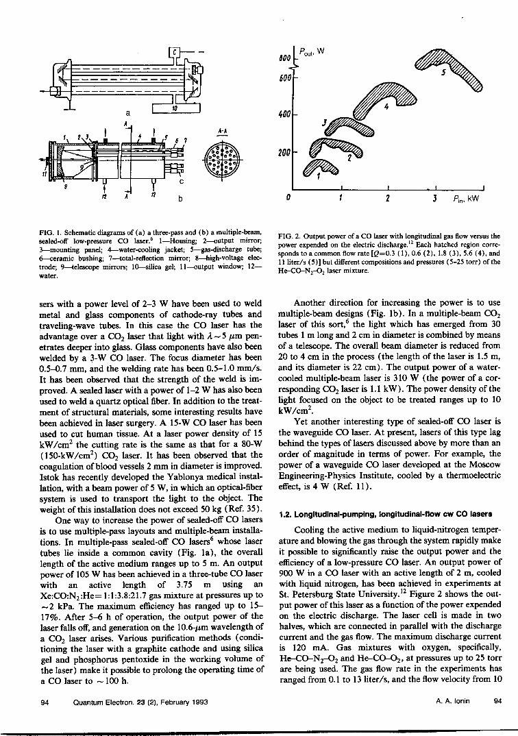
FIG. 2. Output power of a CO laser with longitudinal gas flow versus thepower expended on the electric discharge.12 Each hatched region corre-sponds to a common flow rate [g=0.3 (1), 0.6 (2), 1.8 (3), 5.6 (4), and11 liter/s (5)] but different compositions and pressures (5-25 torr) of theHe-CO-N2-O2 l
aser mixture.
sers with a power level of 2-3 W have been used to weldmetal and glass components of cathode-ray tubes andtraveling-wave tubes. In this case the CO laser has theadvantage over a CO2 laser that light with A — 5 /xm pen-etrates deeper into glass. Glass components have also beenwelded by a 3-W CO laser. The focus diameter has been0.5-0.7 mm, and the welding rate has been 0.5-1.0 mm/s.It has been observed that the strength of the weld is im-proved. A sealed laser with a power of 1-2 W has also beenused to weld a quartz optical fiber. In addition to the treat-ment of structural materials, some interesting results havebeen achieved in laser surgery. A 15-W CO laser has beenused to cut human tissue. At a laser power density of 15kW/cm2 the cutting rate is the same as that for a 80-W(150-kW/cm2) CO2 laser. It has been observed that thecoagulation of blood vessels 2 mm in diameter is improved.Istok has recently developed the Yablonya medical instal-lation, with a beam power of 5 W, in which an optical-fibersystem is used to transport the light to the object. Theweight of this installation does not exceed 50 kg (Ref. 35).
One way to increase the power of sealed-off CO lasersis to use multiple-pass layouts and multiple-beam installa-tions. In multiple-pass sealed-off CO lasers6 whose lasertubes lie inside a common cavity (Fig. la), the overalllength of the active medium ranges up to 5 m. An outputpower of 105 W has been achieved in a three-tube CO laserwith an active length of 3.75 m using anXe:CO:N2:He= 1:1:3.8:21.7 gas mixture at pressures up to~2 kPa. The maximum efficiency has ranged up to 15-17%. After 5-6 h of operation, the output power of thelaser falls off, and generation on the 10.6-/im wavelength ofa CO2 laser arises. Various purification methods (condi-tioning the laser with a graphite cathode and using silicagel and phosphorus pentoxide in the working volume ofthe laser) make it possible to prolong the operating time ofa CO laser to ~ 100 h.
Another direction for increasing the power is to usemultiple-beam designs (Fig. Ib). In a multiple-beam CO2
laser of this sort,6 the light which has emerged from 30tubes 1 m long and 2 cm in diameter is combined by meansof a telescope. The overall beam diameter is reduced from20 to 4 cm in the process (the length of the laser is 1.5 m,and its diameter is 22 cm). The output power of a water-cooled multiple-beam laser is 310 W (the power of a cor-responding CO2 laser is 1.1 kW). The power density of thelight focused on the object to be treated ranges up to 10kW/cm2.
Yet another interesting type of sealed-off CO laser isthe waveguide CO laser. At present, lasers of this type lagbehind the types of lasers discussed above by more than anorder of magnitude in terms of power. For example, thepower of a waveguide CO laser developed at the MoscowEngineering-Physics Institute, cooled by a thermoelectriceffect, is 4 W (Ref. 11).
1.2. Longitudinal-pumping, longitudinal-flow cw CO lasers
Cooling the active medium to liquid-nitrogen temper-ature and blowing the gas through the system rapidly makeit possible to significantly raise the output power and theefficiency of a low-pressure CO laser. An output power of900 W in a CO laser with an active length of 2 m, cooledwith liquid nitrogen, has been achieved in experiments atSt. Petersburg State University.12 Figure 2 shows the out-put power of this laser as a function of the power expendedon the electric discharge. The laser cell is made in twohalves, which are connected in parallel with the dischargecurrent and the gas flow. The maximum discharge currentis 120 mA. Gas mixtures with oxygen, specifically,He-CO-N2-O2 and He-CO-O2, at pressures up to 25 torrare being used. The gas flow rate in the experiments hasranged from 0.1 to 13 liter/s, and the flow velocity from 10
94 Quantum Electron. 23 (2), February 1993 A. A. lonin 94
100 ISP 300
IV, J/g
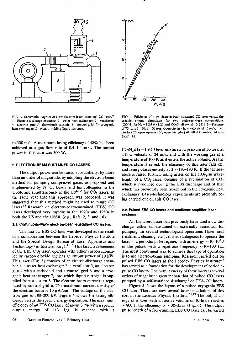
FIG. 3. Schematic diagram of a cw electron-beam-sustained CO laser.'8
1—Electric-discharge chamber; 2—water heat exchanger; 3—ventilator;4—electron gun; 5—thermionic cathode; 6—control grid; 7—cryogenicheat exchanger; 8—cistern holding liquid nitrogen.
to 300 m/s. A maximum lasing efficiency of 45% has beenachieved at a gas flow rate of 0.4—1 liter/s. The outputpower in this case was 300 W.
2. ELECTRON-BEAM-SUSTAINED CO LASERS
The output power can be raised substantially, by morethan an order of magnitude, by adopting the electron-beammethod for pumping compressed gases, as proposed andimplemented by N. G. Basov and his colleagues in theUSSR and simultaneously in the US13'14 for CO2 lasers. Inthe same year that this approach was proposed, it wassuggested that this method might be used to pump COlasers.15 Research on electron-beam-sustained (BBS) COlasers developed very rapidly in the 1970s and 1980s inboth the US and the USSR (e.g., Refs. 2, 3, and 16).
2.1. Continuous-wave electron-beam-sustained CO lasers.
The first cw BBS CO laser was developed as the resultof a collaboration between the Lebedev Physics Instituteand the Special Design Bureau of Laser Apparatus andTechnology (in Ekaterinburg).17'18 This laser, a refinementof the BBS CO2 laser, operates with either carbon monox-ide or carbon dioxide and has an output power of 10 kW.This laser (Fig. 3) consists of an electric-discharge cham-ber 1, a water heat exchanger 2, a ventilator 3, an electrongun 4 with a cathode 5 and a control grid 6, and a cryo-genic heat exchanger 7, into which liquid nitrogen is sup-plied from a cistern 8. The electron beam current is regu-lated by control grid 6. The maximum current density ofthe electron beam is 10 /zA/cm2. The voltage on the elec-tron gun is 180-200 kV. Figure 4 shows the lasing effi-ciency versus the specific energy deposition. The maximumefficiency of an EBS CO laser, of about 37% with a specificoutput energy of 113 J/g, is reached with a
FIG. 4. Efficiency of a cw electron-beam-sustained CO laser versus thespecific energy deposition for two active-mixture compositions[CO:N2:Ar:He= 1:2:8:9 (1,2) and CO:N2:He= 1:9:10 (3)]. 1—Pressureof 75 torr; 2—20; 3—50 torr. Open circles) flow velocity of 15 m/s; filledcircles) 20; open squares) 30; open triangles) 41; filled triangles) 24 m/s(Ref. 18).
CO:N2:He= 1:9:10 laser mixture at a pressure of 50 torr, ata flow velocity of 24 m/s, and with the working gas at atemperature of 100 K as it enters the active volume. As thetemperature is raised, the efficiency of this laser falls off",and lasing ceases entirely at T~ 170-190 K. If the temper-ature is raised further, lasing arises on the 10.6-^m wave-length of a CO2 laser, because of a sublimation of CO2
which is produced during the EBS discharge and of thatwhich has previously been frozen out in the cryogenic heatexchanger. Laser-technology experiments are presently be-ing carried out on this CO laser.
2.2. Pulsed EBS CO lasers and oscillator-amplifier lasersystems
All the lasers described previously have used a cw dis-charge, either self-sustained or externally sustained, forpumping. In several technological operations (laser heattreatment, cleaning, etc.), it is advantageous to operate thelaser in a periodic-pulse regime, with an energy ~ 10-103 Jin the pulses, with a repetition frequency ~ 10-100 Hz.The most convenient way to achieve this type of operationis to use electron-beam pumping. Research carried out onpulsed EBS CO lasers at the Lebedev Physics Institute2'3
has served as a foundation for the development of periodic-pulse CO lasers. The output energy of these lasers is severalorders of magnitude greater than that of pulsed CO laserspumped by a self-sustained discharge8 or TEA-CO lasers.
Figure 5 shows the layout of a pulsed cryogenic EBSCO laser. There are now several laser installations of thissort in the Lebedev Physics Institute.2'3'19 The output en-ergy of a laser with an active volume of 10 liters reaches-800 J; the efficiency is -30-35% (Fig. 6). The outputpulse length of a free-running EBS CO laser can be varied
95 Quantum Electron. 23 (2), February 1993 A. A. lonin 95

FIG. 5. Schematic design of a pulsed electron-beam-sustained CO laser.2 1—Calorimeter; 2—photodetector; 3—trigger generator; 4—circuit fortriggering the pulse voltage generator; 5—circuit for measuring electrical parameters; 6—attenuator; 7—pulse voltage generator; 8—power supply forpulse voltage generator; 9—circuit for heating the cathode of the electron gun; 10—gas inlet and outlet; 11—liquid-nitrogen loop; 12—spectrograph.
20
10
0 100 300 500Qin Jl(liter • amagat)
FIG. 6. Output energy 0^ (4-6) and efficiency ij (1-3) versus thespecific energy deposition Qm. \, 3, 4, 6—Electron-beam-sustained COlaser; 2, 5—BBS CO2 laser. 3, 6) A~3; 1, 4) 5; 2, 5) 10 fim. JV=0.5amagat, P= 10 liters (Ref. 19).
from 30 ps to 3 ms by varying the CO concentration from100 to 2.5%. At the extreme points, the efficiency of thelaser falls off to 5%. At the maximum efficiency, the lengthof the output pulse is ~ 500 /js. The spectral range of theoutput is —4.8-6.0 /xm. With different optics, this laser canoperate on the first overtone of the CO molecule, with anoutput energy of 50 J and an efficiency ~5%. With differ-ent optics, and also with the CO-N2-He mixture replacedby a CO2-N2-He mixture, this laser can operate as a CO2
laser with an energy ~350 J (/»=0.5 atm; Fig. 6). Theoutput energy and efficiency of these lasers vary with thespecific energy deposition in the electron-beam-sustaineddischarge as shown in Fig. 6. These results were found inthe same experimental apparatus.
With Q switching of the cavity it becomes possible togenerate pulses 0.2-10 /AS long at an efficiency ~5% (Ref.19). The sequential operation of the cavity of an BBS COlaser with Q switching with a time interval greater than therecovery time of the population inversion in the active me-dium leads to the generation of a train of "short"microsecond-range pulses at an efficiency close to that of afree-running BBS CO laser (Fig. 7b).21
The best way to control the temporal and spectralcharacteristics of CO lasers is to use oscillator-amplifierlaser systems, in which a laser oscillator of modest powerdetermines the temporal and spectral composition of theoutput. These are the most convenient systems for trans-porting radiation through the atmosphere, e.g., to a target
96 Quantum Electron. 23 (2), February 1993 A. A. lonin 96
9 7 «
\\
f 7 0 5 7 8
b
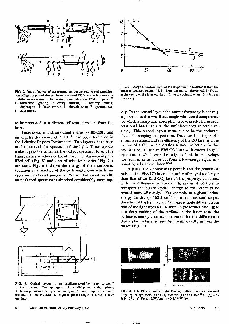
FIG. 7. Optical layouts of experiments on the generation and amplifica-tion of light of pulsed electron-beam-sustained CO lasers, a: In a selectivemultifrequency regime, b: In a regime of amplification of "short" pulses.21
1—Diffraction grating; 2—cavity mirrors; 3—rotating mirror;4—diaphragms; 5—laser mirror; 6—photodetector; 7—spectrometer;8—calorimeter.
to be processed at a distance of tens of meters from thelaser.
Laser systems with an output energy ~ 100-200 J andan angular divergence of 2 • 10~4 have been developed inthe Lebedev Physics Institute.20'21 Two layouts have beenused to control the spectrum of the light. These layoutsmake it possible to adjust the output spectrum to suit thetransparency windows of the atmosphere. An in-cavity air-filled cell (Fig. 8) and a set of selective cavities (Fig. 7a)are used. Figure 9 shows the energy of the transportedradiation as a function of the path length over which thisradiation has been transported. We see that radiation withan unshaped spectrum is absorbed considerably more rap-
FIG. 8. Optical layout of an oscillator-amplifier laser system.20
1—Calorimeters; 2—diaphragms; 3—parallel-plane CaF2 plates;4—telescope mirrors; 5—spectrum analyzer; 6—laser amplifier; 7—laseroscillator; 8—He-Ne laser; L-length of path; /-length of cavity of laseroscillator.
JO L, m
FIG. 9. Energy of the laser light at the target versus the distance from thetarget to the laser system.20 1, 3—Experimental; 2—theoretical. 1) No airin the cavity of the laser oscillator; 2) with a column of air 15m long inthis cavity.
idly. In the second layout the output frequency is activelyadjusted in such a way that a single vibrational component,for which atmospheric absorption is low, is selected in eachrotational band (this is the multifrequency selective re-gime). This second layout turns out to be the optimumchoice for shaping the spectrum. The cascade lasing mech-anism is retained, and the efficiency of the CO laser is closeto that of a CO laser operating without selection. In thiscase it is best to use an BBS CO laser with external-signalinjection, in which case the output of this laser developsnot from intrinsic noise but from a low-energy signal im-posed by a laser oscillator.20'21
A particularly noteworthy point is that the generationpulse of the BBS CO laser is an order of magnitude longerthan that of an BBS CO2 laser. This property, combinedwith the difference in wavelength, makes it possible totransport the pulsed optical energy to the object to betreated more efficiently.22 For example, at a given opticalenergy density (~100 J/cm2) on a stainless steel target,the effect of the light from a CO laser is quite different fromthat of the light from a CO2 laser. In the former case, thereis a deep melting of the surface; in the latter case, thesurface is merely cleaned. The reason for the difference isthat a plasma burst screens light with A~ 10 /xm from thetarget (Fig. 10).
FIG. 10. Left: Plasma bursts. Right: Damage inflicted on a stainless steeltarget by the light from (a) a CO2 laser and (b) a CO laser.22 a—&„, = 55J; b—57 J. a) PX6.1 MW/cm2; b) 0.45 MW/cm2.
97 Quantum Electron. 23 (2), February 1993 A. A. lonin 97
2.3. Periodic-pulse EBS CO laser
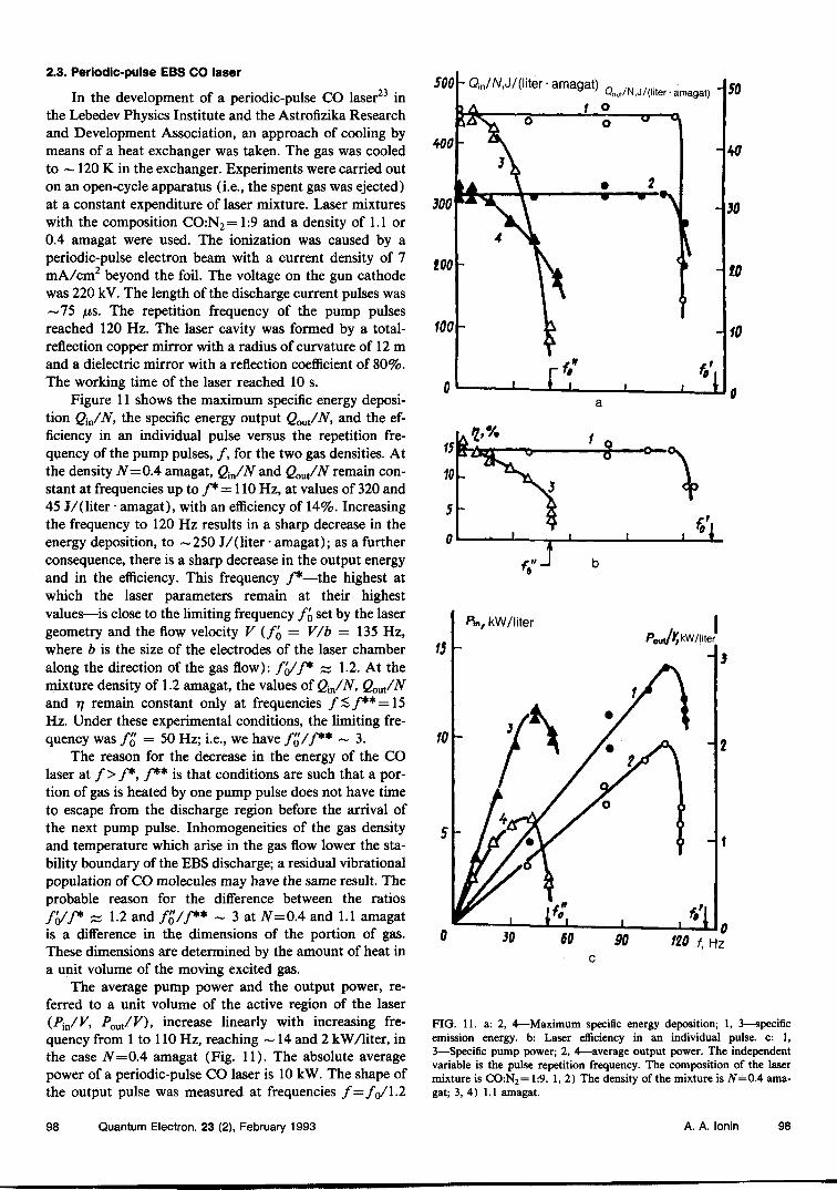
In the development of a periodic-pulse CO laser23 inthe Lebedev Physics Institute and the Astrofizika Researchand Development Association, an approach of cooling bymeans of a heat exchanger was taken. The gas was cooledto ~ 120 K in the exchanger. Experiments were carried outon an open-cycle apparatus (i.e., the spent gas was ejected)at a constant expenditure of laser mixture. Laser mixtureswith the composition CO:N2=1:9 and a density of 1.1 or0.4 amagat were used. The ionization was caused by aperiodic-pulse electron beam with a current density of 7mA/cm2 beyond the foil. The voltage on the gun cathodewas 220 kV. The length of the discharge current pulses was~75 /xs. The repetition frequency of the pump pulsesreached 120 Hz. The laser cavity was formed by a total-reflection copper mirror with a radius of curvature of 12 mand a dielectric mirror with a reflection coefficient of 80%.The working time of the laser reached 10 s.
Figure 11 shows the maximum specific energy deposi-tion Qin/N, the specific energy output Qout/N, and the ef-ficiency in an individual pulse versus the repetition fre-quency of the pump pulses, /, for the two gas densities. Atthe density N=OA amagat, Qin/N and Qout/N remain con-stant at frequencies up to /*= 110 Hz, at values of 320 and45 J/(liter • amagat), with an efficiency of 14%. Increasingthe frequency to 120 Hz results in a sharp decrease in theenergy deposition, to ~250 J/(liter • amagat); as a furtherconsequence, there is a sharp decrease in the output energyand in the efficiency. This frequency /*—the highest atwhich the laser parameters remain at their highestvalues—is close to the limiting frequency /Q set by the lasergeometry and the flow velocity V (f'Q — V/b =135 Hz,where b is the size of the electrodes of the laser chamberalong the direction of the gas flow): f'o/f* zz 1.2. At themixture density of 1.2 amagat, the values of Qm/N, Qout/Nand 17 remain constant only at frequencies /;$/** = 15Hz. Under these experimental conditions, the limiting fre-quency was /o = 50 Hz; i.e., we have f'o/f** ~ 3.
The reason for the decrease in the energy of the COlaser at />/*, /** is that conditions are such that a por-tion of gas is heated by one pump pulse does not have timeto escape from the discharge region before the arrival ofthe next pump pulse. Inhomogeneities of the gas densityand temperature which arise in the gas flow lower the sta-bility boundary of the EBS discharge; a residual vibrationalpopulation of CO molecules may have the same result. Theprobable reason for the difference between the ratios/<//•* ^ 1.2 and /£//** ~ 3 at N=0.4 and 1.1 amagatis a difference in the dimensions of the portion of gas.These dimensions are determined by the amount of heat ina unit volume of the moving excited gas.
The average pump power and the output power, re-ferred to a unit volume of the active region of the laser(Pm/V, Pml/V), increase linearly with increasing fre-quency from 1 to 110 Hz, reaching ~ 14 and 2 kW/liter, inthe case N=OA amagat (Fig. 11). The absolute averagepower of a periodic-pulse CO laser is 10 kW. The shape ofthe output pulse was measured at frequencies /=/o/1.2
500hQin/A/,J/(liter- amagat) _
I
120 f, HZ
FIG. 11. a: 2, 4—Maximum specific energy deposition; 1, 3—specificemission energy, b: Laser efficiency in an individual pulse, c: 1,3—Specific pump power; 2, 4—average output power. The independentvariable is the pulse repetition frequency. The composition of the lasermixture is CO:N2= 1:9. 1,2) The density of the mixture is #=0.4 ama-gat; 3, 4) 1.1 amagat.
98 Quantum Electron. 23 (2), February 1993 A. A. lonin 98
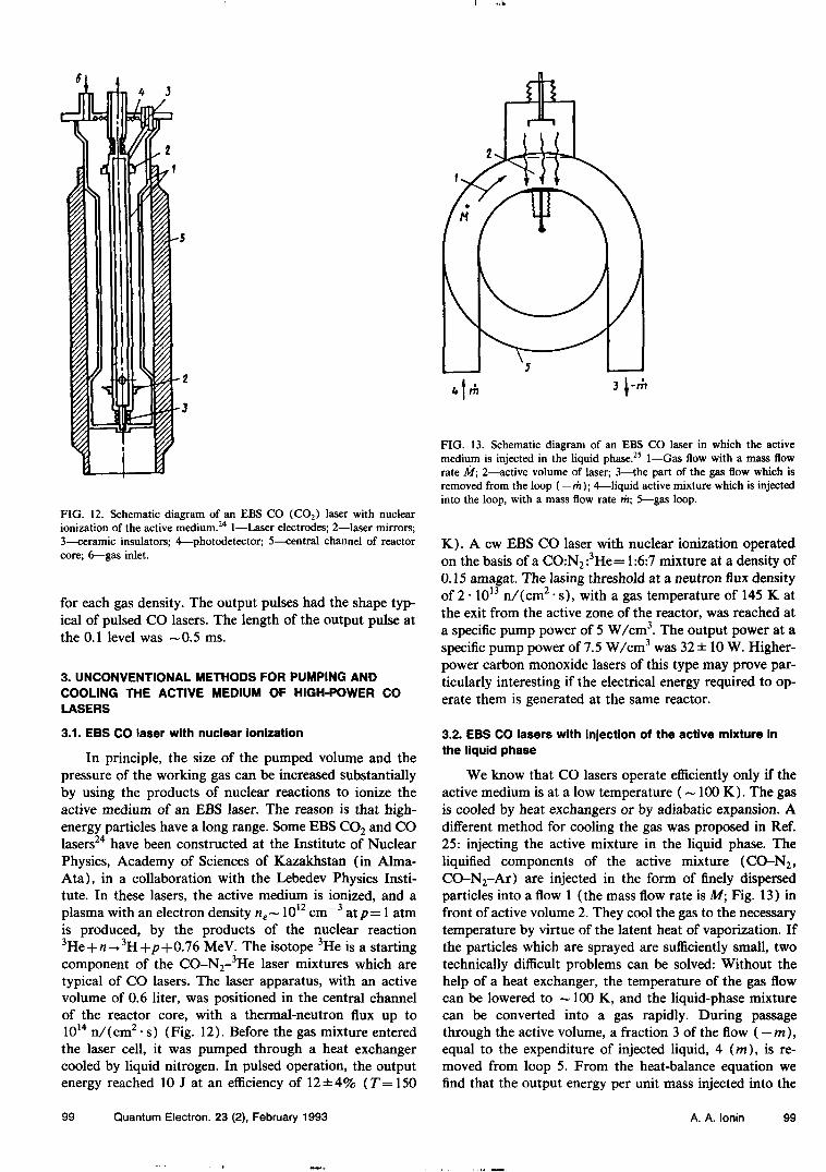
FIG. 12. Schematic diagram of an BBS CO (CO2) laser with nuclearionization of the active medium.24 1—Laser electrodes; 2—laser mirrors;3—ceramic insulators; 4—photodetector; 5—central channel of reactorcore; 6—gas inlet.
for each gas density. The output pulses had the shape typ-ical of pulsed CO lasers. The length of the output pulse atthe 0.1 level was ~0.5 ms.
3. UNCONVENTIONAL METHODS FOR PUMPING ANDCOOLING THE ACTIVE MEDIUM OF HIGH-POWER COLASERS
3.1. EBS CO laser with nuclear ionization
In principle, the size of the pumped volume and thepressure of the working gas can be increased substantiallyby using the products of nuclear reactions to ionize theactive medium of an EBS laser. The reason is that high-energy particles have a long range. Some EBS CO2 and COlasers24 have been constructed at the Institute of NuclearPhysics, Academy of Sciences of Kazakhstan (in Alma-Ata), in a collaboration with the Lebedev Physics Insti-tute. In these lasers, the active medium is ionized, and aplasma with an electron density ne~ 1012 cm~3 atp= 1 atmis produced, by the products of the nuclear reaction3He + «^3H+/?+0.76 MeV. The isotope 3He is a startingcomponent of the CO-N2-
3He laser mixtures which aretypical of CO lasers. The laser apparatus, with an activevolume of 0.6 liter, was positioned in the central channelof the reactor core, with a thermal-neutron flux up to1014 n/(cm2 • s) (Fig. 12). Before the gas mixture enteredthe laser cell, it was pumped through a heat exchangercooled by liquid nitrogen. In pulsed operation, the outputenergy reached 10 J at an efficiency of 12 ±4% (jT=150
FIG. 13. Schematic diagram of an EBS CO laser in which the activemedium is injected in the liquid phase.25 1—Gas flow with a mass flowrate A/; 2—active volume of laser; 3—the part of the gas flow which isremoved from the loop ( — m); A—liquid active mixture which is injectedinto the loop, with a mass flow rate m; 5—gas loop.
K). A cw EBS CO laser with nuclear ionization operatedon the basis of a CO:N2:
3He= 1:6:7 mixture at a density of0.15 amagat. The lasing threshold at a neutron flux densityof 2 • 1013 n/(cm2 • s), with a gas temperature of 145 K atthe exit from the active zone of the reactor, was reached ata specific pump power of 5 W/cm3. The output power at aspecific pump power of 7.5 W/cm3 was 32 ± 10 W. Higher-power carbon monoxide lasers of this type may prove par-ticularly interesting if the electrical energy required to op-erate them is generated at the same reactor.
3.2. EBS CO lasers with injection of the active mixture inthe liquid phase
We know that CO lasers operate efficiently only if theactive medium is at a low temperature (~ 100 K). The gasis cooled by heat exchangers or by adiabatic expansion. Adifferent method for cooling the gas was proposed in Ref.25: injecting the active mixture in the liquid phase. Theliquified components of the active mixture (CO-N2,CO-N2-Ar) are injected in the form of finely dispersedparticles into a flow 1 (the mass flow rate is Af; Fig. 13) infront of active volume 2. They cool the gas to the necessarytemperature by virtue of the latent heat of vaporization. Ifthe particles which are sprayed are sufficiently small, twotechnically difficult problems can be solved: Without thehelp of a heat exchanger, the temperature of the gas flowcan be lowered to ~ 100 K, and the liquid-phase mixturecan be converted into a gas rapidly. During passagethrough the active volume, a fraction 3 of the flow ( — m),equal to the expenditure of injected liquid, 4 (m), is re-moved from loop 5. From the heat-balance equation wefind that the output energy per unit mass injected into the
99 Quantum Electron. 23 (2), February 1993 A. A. lonin 99
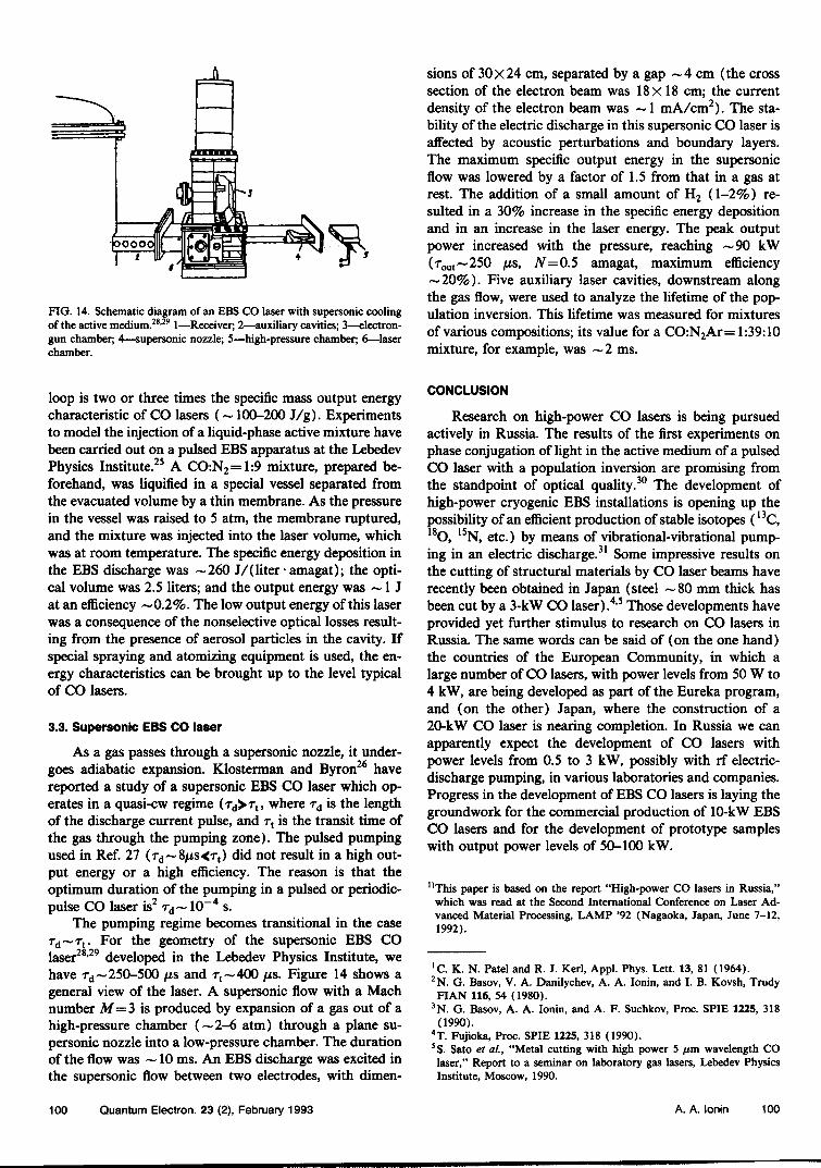
FIG. 14. Schematic diagram of an EBS CO laser with supersonic coolingof the active medium.28'291—Receiver; 2—auxiliary cavities; 3—electron-gun chamber; 4—supersonic nozzle; 5—high-pressure chamber; 6—laserchamber.
sions of 30x24 cm, separated by a gap ~4 cm (the crosssection of the electron beam was 18x18 cm; the currentdensity of the electron beam was ~1 mA/cm2). The sta-bility of the electric discharge in this supersonic CO laser isaffected by acoustic perturbations and boundary layers.The maximum specific output energy in the supersonicflow was lowered by a factor of 1.5 from that in a gas atrest. The addition of a small amount of H2 (1-2%) re-sulted in a 30% increase in the specific energy depositionand in an increase in the laser energy. The peak outputpower increased with the pressure, reaching ~90 kW(rout~250 /is, N=0.5 amagat, maximum efficiency~20%). Five auxiliary laser cavities, downstream alongthe gas flow, were used to analyze the lifetime of the pop-ulation inversion. This lifetime was measured for mixturesof various compositions; its value for a CO:N2Ar= 1:39:10mixture, for example, was ~2 ms.
loop is two or three times the specific mass output energycharacteristic of CO lasers (—100-200 J/g). Experimentsto model the injection of a liquid-phase active mixture havebeen carried out on a pulsed EBS apparatus at the LebedevPhysics Institute.25 A CO:N2=1:9 mixture, prepared be-forehand, was liquified in a special vessel separated fromthe evacuated volume by a thin membrane. As the pressurein the vessel was raised to 5 atm, the membrane ruptured,and the mixture was injected into the laser volume, whichwas at room temperature. The specific energy deposition inthe EBS discharge was ~260 J/(liter-amagat); the opti-cal volume was 2.5 liters; and the output energy was — 1 Jat an efficiency ~0.2%. The low output energy of this laserwas a consequence of the nonselective optical losses result-ing from the presence of aerosol particles in the cavity. Ifspecial spraying and atomizing equipment is used, the en-ergy characteristics can be brought up to the level typicalof CO lasers.
3.3. Supersonic EBS CO laser
As a gas passes through a supersonic nozzle, it under-goes adiabatic expansion. Klosterman and Byron26 havereported a study of a supersonic EBS CO laser which op-erates in a quasi-cw regime (rd>rt, where rd is the lengthof the discharge current pulse, and r, is the transit time ofthe gas through the pumping zone). The pulsed pumpingused in Ref. 27 (rd~8/is<rt) did not result in a high out-put energy or a high efficiency. The reason is that theoptimum duration of the pumping in a pulsed or periodic-pulse CO laser is2 rd~ 10~4 s.
The pumping regime becomes transitional in the caseTd~T t. For the geometry of the supersonic EBS COlaser28'29 developed in the Lebedev Physics Institute, wehave rd~250-500 /is and rt~400 /is. Figure 14 shows ageneral view of the laser. A supersonic flow with a Machnumber M=3 is produced by expansion of a gas out of ahigh-pressure chamber (~2-6 atm) through a plane su-personic nozzle into a low-pressure chamber. The durationof the flow was ~ 10 ms. An EBS discharge was excited inthe supersonic flow between two electrodes, with dimen-
CONCLUSION
Research on high-power CO lasers is being pursuedactively in Russia. The results of the first experiments onphase conjugation of light in the active medium of a pulsedCO laser with a population inversion are promising fromthe standpoint of optical quality.30 The development ofhigh-power cryogenic EBS installations is opening up thepossibility of an efficient production of stable isotopes (13C,18O, 15N, etc.) by means of vibrational-vibrational pump-ing in an electric discharge.31 Some impressive results onthe cutting of structural materials by CO laser beams haverecently been obtained in Japan (steel ~80 mm thick hasbeen cut by a 3-kW CO laser).4'5 Those developments haveprovided yet further stimulus to research on CO lasers inRussia. The same words can be said of (on the one hand)the countries of the European Community, in which alarge number of CO lasers, with power levels from 50 W to4 kW, are being developed as part of the Eureka program,and (on the other) Japan, where the construction of a20-kW CO laser is nearing completion. In Russia we canapparently expect the development of CO lasers withpower levels from 0.5 to 3 kW, possibly with rf electric-discharge pumping, in various laboratories and companies.Progress in the development of EBS CO lasers is laying thegroundwork for the commercial production of 10-kW EBSCO lasers and for the development of prototype sampleswith output power levels of 50-100 kW.
"This paper is based on the report "High-power CO lasers in Russia,"which was read at the Second International Conference on Laser Ad-vanced Material Processing, LAMP '92 (Nagaoka, Japan, June 7-12,1992).
'C. K. N. Patel and R. J. Kerl, Appl. Phys. Lett. 13, 81 (1964).2N. G. Basov, V. A. Danilychev, A. A. lonin, and I. B. Kovsh, TrudyFIAN 116, 54 (1980).
3N. G. Basov, A. A. lonin, and A. F. Suchkov, Proc. SPIE 1225, 318(1990).
4T. Fujioka, Proc. SPIE 1225, 318 (1990).5S. Sato et al, "Metal cutting with high power 5 /an wavelength COlaser," Report to a seminar on laboratory gas lasers, Lebedev PhysicsInstitute, Moscow, 1990.
100 Quantum Electron. 23 (2), February 1993 A. A. lonin 100

6V. S. Aleinikov and V. I. Masychev, Carbon Dioxide Lasers [in Russian](Radio i Svyaz', Moscow, 1990).
7N. N. Sobolev and V. V. Sokovikov, Kvant. Elektron. (Moscow), 2, 3(1972) [Sov. J. Quantum Electron. 2, 305 (1973)].
8 A. V. Anokhin, S. V. Markova, and G. G. Petrash, Kratk. Soobshch.Fiz. FIAN, No. 8, 15 (1970).
9T. F. Kacheva, V. N. Ochkin, and N. N. Sobolev, Kvant. Elektron.(Moscow) 3, 58 (1973) [Sov. J. Quantum Electron. 3, 484 (1973)].
10 N. G. Basov, V. A. Danilychev, A. A. lonin, I. B. Kovsh, and V. A.Sobolev, Kratk. Soobshch. Fiz., No. 6, 3 (1974).
11 A. G. Gerasimchuk, S. T. Kornilov, E. D. Protsenko, and S. I. Tymper,Prib. Tekh. Eksp., No. 3, 148 (1991).
12G. M. Grigor'yan, B. M. Dymshits, and Yu. Z. lonikh, Kvant. Elek-tron. (Moscow) 17, 669 (1990) [Sov. J. Quantum Electron. 20, 591(1990)].
I3N. G. Basov, E. M. Belenov, V. A. Danilychev, and A. F. Suchkov,Kvant. Elektron. (Moscow) I, 121 (1971) [Sov. J. Quantum Electron.1, 306 (1971)].
14 S. A. Fenstermacher, M. J. Nutter, J. P. Rink, and K. Boyer, Bull. Am.Phys. Soc. 16,42 (1971).
15 N. G. Basov, E. M. Belenov, V. A. Danilychev, and A. F. Suchkov,Pis'ma Zh. Eksp. Teor. Fiz. 14, 545 (1971) [JETP Lett. 14, 375(1971)].
16R. E. Center, in: Laser Handbook (North-Holland, Amsterdam, 1979),p. 89.
17 A. P. Averin, N. G. Basov, E. P. Glotov, V. A. Danilychev, et al,Kvant. Elektron. (Moscow) 9,2357 (1982) [Sov. J. Quantum Electron.12, 1537 (1982)].
18 A. P. Averin, N. G. Basov, E. P. Glotov, V. A. Danilychev, et al., Izv.Akad. Nauk SSSR, Ser. Fiz., No. 8, 1519 (1983).
19 N. G. Basov, A. A. lonin, and I. B. Kovsh, Infrared Phys. 25, 47(1985).
20 V. Yu. Ananiev, V. A. Danilychev, A. A. lonin, A. A. Kotkov, A. P.Lytkin, and D. V. Sinitsyn, Int. J. Infrared Millimeter Waves 8, 549(1987).
21V. Yu. Ananiev, V. A. Danilychev, A. A. lonin, A. A. Kotkov, A. P.
Lytkin, and D. V. Sinitsyn, Infrared Phys. 29, 347 (1989).22 A. A. lonin, A. A. Kotkov, D. V. Sinitsyn, A. F. Suchkov, et al.,
Report N36/90, Lebedev Physics Institute, Moscow, 1990.23 A. P. Averin, I. K. Babaev, N. G. Basov, A. A. lonin, et a!., Kvant.
Elektron. (Moscow) 17, 493 (1990) [Sov. J. Quantum Electron. 20,427 (1990)].
24 G. A. Batyrbekov, A. O. Beisebaev, Sh. K. Gizatulin, V. A. Danilychev,A. A. lonin, et al., Kvant. Elektron. (Moscow) 9, 1493 (1982) [Sov. J.Quantum Electron. 12, 955 (1982)].
25 E. P. Glotov, V. A. Danilychev, A. A. lonin, A. V. Kuchaev, and D. V.Sinitsyn, Kratk. Soobshch. Fiz., No. 12, 30 (1985).
26E. L. Klosterman and S. R. Byron, J. Appl. Phys. 51, 5168 (1980).27 W. Mayerhofer, W. Heunnig, R. Nowack, and H. Hiigel, Proceedings of
the Sixth International Symposium, Jerusalem, 1986 (Berlin, 1987), p.237.
28 A. lonin, A. Kotkov, M. Minkovsky, and D. Sinitsyn, Proc. SPIE 1397,453 (1990).
29 A. lonin, Proceedings of the Fourth International Congress on OpticalScience and Engineering, ECO-IV (The Hague, The Netherlands,1991), paper 1502-41.
30D. V. Belousov, A. M. Borodin, M. V. Bunkina, V. A. Gurashvili,et al, in: Proceedings of the Fourteenth International Conference onCoherent and Nonlinear Optics [in Russian] (Leningrad, 1991), p. 177.
31 J. Rich and R. Bergman, in: Nonequilibrium Vibrational Kinetics [Rus-sian translation] (Mir, Moscow, 1989), p. 313.
32N. N. Sobolev and V. V. Sokovikov, Usp. Fiz. Nauk 110, 191 (1973)[Sov. Phys. Usp. 16, 350 (1973)].
33 A. A. lonin, I. B. Kovsh, V. A. Sobolev, and B. M. Urin, "High-pressure electric-discharge IR lasers and their applications," in:Scientific and Technological Progress. Radioengineering Series [in Rus-sian] Vol. 32 (VINITI, Moscow, 1984).
34J. Rich, in: Gas Lasers [Russian translation] (Mir, Moscow, 1986), p.148.
35 Laser Market, No. 2, 23 (1992).
Translated by D. Parsons
101 Quantum Electron. 23 (2), February 1993 A. A. lonin 101