Embed Size (px)
Citation preview

THE
OK
ON
TTF COMPANY
HIG
H
POW
ER, LOW N
OISE
PU
LSE CA
ILES
Second
Qu
arte
rly P
rog
ress R
eport
April
15, 1953 to A
ug
ust
15, 1953
Co
ntract
No. DA
36
-03
9 SC
42669

?
HIGH POWER NOISE FREE PULSE CABLE
SECOND QUARTERLY REPORT
May 15, 1953 to August 15, 1953
CONTRACT NO.
FILE NO.
DEFT OF ARMY PROJECT NO.
PLACED BY:
DA 36-039 SC 1*2669
13259-PH-53-9l(3l*03)
2006c
U. S. Army
Signal Corps Engineering Laboratories
Fort Monnouth, New Jersey
THE OXDNTTE COMPANY
PASSAIC, NEW JERSEY
-L i

- a
HIGH POWER NOISE FREE PULSE CABLE
SECOND QUARTERLY REPORT
May 15, 1953 - August 15, 1953
(
I. OBJECT
To design and manufacture pulse cables of 50, 25 and 12-1/2
ohms capable of handling from 5 to kO megawatts of peak pulse
power with a minimum of radiated noise and capable of operating
over an ambient temperature range of +55 "C to -55 *C at a
maximum hotspot temperature of 125*C.
CONTRACT NO.
FILE NO.
EEFT. OF ARMY PROJECT NO.
SIGNAL CORP. PROJECT NO.
DA 36-039 SC 42669
13259-PH-53-9l(31*03)
3-26-00-602
2006c
PREPARED BY:
APPROVED BY:
Robert G. Feller
Frank Gocding

- b -
SECOND QUARTERLY REPORT
High Power, Noise Free Pulse Cable
II COWTENTS Page
I Object a
II Table of Contents b-d
III Purpose 1
IV Abstract 2
V Conferences 3
VI Factual Data U-l6
A. Slab Testing k
1. Conducting Paint 1*
2. Type O223U9A Butyl Slab h
a. Power Factor Vs. Temperature 1»
b. Dielectric Constant Vs. Temperature 5
3• Type DC 80 Silicone Rubber Slabs 5
a. Power Factor Vs. Temperature 5
b.' Dielectric Constant Vs. Temperature 5
B. Type BI DC 80 Silicone Rubber Pulse Cable 5
1. Discussion of Progress 5
a. First Trial Cure 6
b. Second Trial Cure 6
c. Third Trial Cure 7
d. Final Cable Cure 7
C. Type AI-B 25 Ohms, 15 KV, 10 megawatt Butyl Pulse Cable 8
1. Discussion of Progress 8
2. Tests 9
a. Attenuation 9
b. Velocity and Characteristic Impedance 9
c. Effect of Semiconducting Compound on SIC .10
- c
Table of Contents(Cont'd) Page
a. Cable SIC and Insulation SIC 10
e. Separation of Losses 11
f. Corona Level 12
g. Power Rating 13
h. Power Factor Vs. time at 125°C Ik
D. Transfer Impedance 15
E. Interchemical Corporation 16
1. Type 1354 Butyl Compound 16
VII Conclusion 17
VIII Program for Next Interval 18
IX Identification of Key Personnel 19
X Time Record 20
XI Curves 21-1*0
Figure 1(2
Figure 2(2
Figure 3(2
Figure k(2
Figure 5(2
Figure 6(2
Figure 7(2
Figure 8(2
figure 9(2
Power Factor Vs. Temperature (0223I+9A Butyl Slab^.... 21
Dielectric Constant Vs. Temperature (O223U9A Butyl Slab) 22
Power Factor Vs. Temperature (DC 80 Slab) 23
Dielectric Constant Vs. Temperature (DC 80 Slab) 2k
Eata relating to Preparation of Semiconducting Films using Silicone Resins and Carbon Black 25
Attenuation Measur ments 26
Attenuation Vs. Frequency Type AI-B Cable 27
Cable Dielectric Constant Vs. Frequency,Type AI-B Cable 28
Dielectric Constant of Insulation Vs. Frequency, Cable AI-B 29
Figure 10(2) Power Factor Vs. Frequency, Cable AI-B 30
Figure 11(2) Separation of Losses, Cable Type AI-B 31
Figure 12(2) Corona Detection 32
Figure 13(2) Power Rating Setup 33
Figure 14(2) Temperature of Inner Braid Vs. Current, Type AI-B CBtle„3li

f - a -
Table of Contents Page
Figure 15(2) Temperature of Inner Braid Vs. Watts DiB6ipated/ft. Cable AI-B 35
Figure 16(2) Power Rating Vs. Frequency, Cable Type AI-B 36
Figure 17(2) Power Factor Vs. Time, Cable Type AI-B 37
Figure 18(2) Z^ Test Circuit #1 38
Figure 19(2) Za0 Test Circuit #2 39
XII References kO

- 1 -
III PURPOSE
To provide services, facilities and materials to conduct
development leading to the establishing of designs for pulse cables,
capable of handling high peak power and exhibiting low noise
radiation and fabrication of samples for component testing purposes.
This period has been devoted to the design and fabrication
of cable type 2515. Type AI has a butyl type insulation and
type BI has a sllicone rubber insulation.

- 2 -
IV ABSTRACT
We have continued our work on our slab testing procedure and are now
painting both sides of the slab with conducting paint. Using this method,
we get a good correlation between the SIC of the slab and the sane compound
In a finished cable.
The power factor and SIC of O223U9A Butyl has been checked over a
temperature range frcm room temperature to 125*C. There le no appreciable
change In SIC and the power factor drops slight;7,
DC80 Slllcone Rubber was also checked. The SIC remains constant while
the power factor drops with temperature.
Several trial cures were made on the Silastic Cable before the whole
cable was cured. A cure In lead followed by an air oven cure gave the
optimum cure according to Dow Corning information.
Tests have been made on type AI-B cable. The resvlts are as follows*
Attenuation/lOO ft. at 1 mc.
Velocity
Corona Level
Impedance
Power Factor
.1U db/lOO ft.
U8.9*
12,000 volt extinction
2k.k ohms at 1 mc.
,9l> at 1 mc.
Cable type AI-A will be completed shortly. This has a semiconducting
layer over the inner braid.
The power rating of the cable has been calculated for operation at a
single frequency. A weighted attenuation is being calculated to determine
the frequency at which the power rating can be obtained.
We are entering an order for a 12-1/2 ohms, type 1215 cable, nrde with
O223U9A Butyl and also a 25 ohm Type 2515 cable made with Interchemical l&U
Butyl Compound.
Different types of semiconducting materials are being investigated for
use on the 25 ohm slllcone cable.

T i
- } -
V CONFERENCES
June 22, 1953 - Discussion on Progress of Contract.
Present were Messrs. J. Spergel, M. Tenter of Squier Laboratory
and Messrs. Gocdlng, Slade and Feller of The Okonlte Company.
The meeting was held at The Okonlte -Company, Passalc, N. J.
The corona levels obtained on the experimental cables were
discussed and It was decided to recheck the values. The use
of an Interlocking armor for a Jacket was discussed.
July 28, 1953 - Present was Mr. Spergel of Squier Laboratory and Messrs. Goodlng,
Feller, and Waldstein of The Okonlte Company.
Mr. Spergel brought pieces of cable to be tested by us in our
Z. - apparatus over a frequency range up to 10 mc. If possible.
The test8 were to include
(a) all braids tied together
(b) outer braid isolated from others.
August 21, 1953 - Discussion of Contract.
Present were Messrs* Gooding, Feller and Waldstein of the
Okonlte Company and Mr. Spergel of Squier Laboratory. The
meeting was held at Squier Laboratory. A general discussion on
the progress on the contract took place. The problem of a
semiconducting material for type Bl Sllastlc cable was discussed.
It was agreed to use a .1 usec pulse width for our power rating
calculations to obtain weighted attenuation. Also check possi-
bility of coloring Butyl material so that the insulation and
semiconducting compound can be easily recognized.

7 - k -
VI FACTUAL DATA
A. Slab Testing
1. Conducting Paint.
a. We have been working on the improvement of our slab testing method
and are now painting the slabs to within a sixteenth of an inch
of the edg? on both sides with aquadag, a conducting paint.
The following are an average of the readings on the same slab of
DC 80 Sillcone rubber at 1,? mc*
C_uufd. P.F.fl
(1) Unpalnted Slab 103.U .37
(2) Painted on both sides 101.8 .96
If we figure in (l) that the losses due to fringe effect are approxi-
mately 5 uufd <Quarterly Report I, Page 10) we have a value of 98.1*
uufA. The large increase in power factor due to painting may be
explained by the decrease in contact resistance between the electrodes
and the surfaces of the slab. It is noted that the use of conducting
paint gives a Increase in power factor of about three times over the
unpalnted slabs. (See Quarterly Report #1 for power factors of
unpalnted slabs). The use of the conducting paint gives a much better
correlation between the SIC of a slab of compound and a cable of the
same type of material. In checking the power factor of a Butyl
insulated cable vs. a slab of Butyl, the power factor of the painted
slab is appreciably higher than that of the cable at room temperature.
2. Type 0223U9A Butyl Slabs.
a. Power Factor Vs. Temperature.
Figure 1(2) shows the variatiot. in Power Factor vs. Temperature of
Type 0223lt9A Butyl at 2.0 megacycles. The slab was held at the Indi-
cated temperature for a period of two hours. There Is a slight
decrease In pow^r factor as the temperature is raised from 22*C

- 5 -
to 100*C. The high power factor at room temperature does not compare
vith the completed cable at room temperature, A similar check is being
made on the completed Butyl cable,
b. Dielectric Constant Vs. Temperature,
The SIC of the Butyl shove no appreciable change over the temperature
range. Figure 2(2)
3. Type DC 80 Silicone Rubber
a. Power Factor vs. Temperature
Tests similar to those on the Butyl were also conducted on the DC 80
Silicone Rubber. Figure 3(2) shows the power factor vs. temperature.
It should be noted that there is a decided decrease in power factor
as the temperature increases. One reason probably is that the Silastic
slab had only one cure prior to the test. Gases are occluded in this
type of compound and are released by a slow heat cycle in a dry oven.
This test is still being carried on at 125*C. Upon completion, a
similar run over the same temperature range will be made on the Silastic
cable.
b. Dielectric Constant Vs. Temperature
Figure U(2) shows.vary good stability in the dielectric constant over
the temperature range at which It was tested.
B. Type BI DC 80 Silicone Rubber Cable.
1. Discussion of Progress
During this quarter type BI cable was completed to the point where the
insulation was anplied. At this point trial cures were made of short
lengths of the cable to give the best cure possible and hence the lowest
power factor consistent with physical strength. Short lengths of the sable
ware first cured in lead in a steam vulcaniter to force the compound into
the braid and hence reduce any corona that might occur. Then the lead
was stripped and a second cure in an electric oven was made to give the

desired final cure. It should be pointed out that silicone rubber has a
peculiar curing schedule. It must be raised to about 1*90°F to set the
compound. This must be done slowly in order to drive off volatile gases in
the compound. From data on DC 80 Silicone Rubber supplied by Dow Corning
a tensile strength in the neighborhood of 720 lbs/in.2 is possible on the
final cure.
a. First Trial Cure.
Two short lengths of uncured cable were precured in lead as follows,
(l) One way valves were placed on each end of both samples.
"A" was placed in a steam vulcanizer for a 275°F-5 min. cure.
"B" was given a 275°F-10 min. cure. The results:
Sample Tensile #/ln.2 Elongation (2")
A 1095 15.^
B 1055 15.^
These results show little difference between the two. Samples
A and B were both undercured at this point. They were then placed
in an electric oven and raised in equal steps to 1*90*F in 12 hours.
The results were as follows.
Sample Tensile #/ln.2 Elongation (2")
A 370 8.1
B 366 7-7
This low tensile was brought about by too rapid an Increase in
temperature to U92*F.
b. Second Trial Cure
Two more samples were cured in steam vulcanizer. Sample C at 275*F for
5 min., Sample D at 258*F for 80 min., 20 minute rise, 20 minutes blowoff
in the large vulcanizer in the factory. Previous tests were made in a
small laboratory vulcanizer. The results are as follows?

- 7 -
Sample Tensile #/ln. Elongatlon(2")
C 1090 15.2
D 961 15.6
It was noted that Sample D appeared cjilte similar to those cured In
the laboratory. These samples were placed In the electric oven and
the temperature raised from 200*F to U92*F In a 2k hour cycle and
held at U92*F for 15 mln.
Sample Tensile #/ln.2 Elongation (2H)
C Ul9 6.2
D 357 5.7
The examination of these samples indicated brittleness and probable
overcure.
Trial Three
Sample E was cured at 258*F for 80 mln. as in the last trial and the
lead stripped, then placed in the electric oven. This was given the
following cure.
300*F for 5 mln.
325*F for 5 ain.
350"F for 10 mln.
then 10* Increments every 10 minutes to l«O0*F for 20 minutes.
This gave the following results.
Sample Tensile #/ln.2 Elongation (2")
E 632 13.1
This cable seemed quite close to the desired cure and It was decided
to cure the entire length as In trial #3.
Final Cable Cure (Type B.l)
(l) The ends of the cable were sealed with one way valves and it was
placed in the vulcanizer for a 258*F 80 minute cure (20 minute rise
20 minutes blowoff). The results are as follows:

,1
- 8 -
Sample Tensile #/ln.2 Elongation (2")
Cable 927 15.6
(2) The cable was then stripped of lead and placed In the electric
oven for the cure described In the third trial. The result -
Sample Tensile #/Kn.2 Elongation (2")
Type Bl Cable 777 l^.O
This cable when tested at 1.5 megacycles has the following values
on a five foot length,
SIC P.F.* ZQ (ohms)
3.19 .U65* 23.U
when a braid was placed over the insulation.
(3) This cable is in braiding at present. We are working on a conducting
paint to be applied uafier the outer braid. Figure 5(2) give Data
concerning the Preparation of Semiconducting Films using Slllcone
Resins and Carbon Black. We are considering the use of DC 803
Resin with Shavlnlgan acetylene Black in a mixture of 10 pints of
black to 100 pts. of resin solid. It should be pointed out that
over a period of tin** this type of conducting paint will migrate
into the slllcone rubber with deteriorating effects. We have written
to Dow Corning concerning a new type of conducting paint which is
said not to have this effect.
C. Type AI-B (2515) 0223U9A Butyl Cable.
1. Discussion of Progress.
During this period Item B of Cable Type AI was completed. (See Quarterly
Report I Page 33 for complete d escrlption). This was the Butyl type
cable with no semiconducting compound over the inner conductor.

4 - 9 -
2, Tests
a. Attenuation.
Figure 6(2) shows the attenuation setup that ve used to test our cable.
By shorting the far end of the cable ve measure the odd multiples of
quarter wavelengths by changing the frequency over the points of
resonance. fXl« la known as the susceptance tirlation method of test. By
using the following formulas the attenuation In decibels per 100 ft.
can be computed.
Attenuation (db/lOO ft.) « 682 Af N ~T fr
Where 1 - length of cable in feet
fr - resonant freq. In megacycles
Af • megacycles between l/2 power points.
N • number of l/U wave lengths under test.
With this cable we carried out the attenuation versus frequency measure-
ments up to 9 quarter wavelengths. Figure 7(2) shows the attenuation vs.
frequency of type AI-B Butyl cable.
b. Velocity and Characteristic Impedance.
The attenuation measurements were made on two lengths of this cable,
(a) 1U7 ft. and (b) 112.6 ft. after samples had been removed from (a).
An average velocity of k9,9f> was obtained on (a) while on (b) 5**.51&
velocity was obtained. Using physical dimensions and capacity per foot
measurement
L - 1^0 logioS uh/lOOO ft.
where d « diameter of cable over inner conductor
D « diameter of cable over insulation
L - lUO log10 -^
L - U7.7 uh/1000 ft.
C - .08U8 ufd./lOOO ft.
therefore ZQ - j£j - ^fMz) - 23.7 ohms

/ - 10 -
Using the velocities obtained above
Length Velocity (I) Zn(ohms)
1U7.61 U9.8 2k,k
112.6 5^.5 22,0
vhere ZQ » 10l600 ohms ^Telocity x Cuufd./YT.
The method In which the inductance Is figured from the dimensions has
been quite accurate in the past. Ve are investigating the variation
in the velocities of the two lengths. By comparison of the SIC values
obtained on a three foot sample and the SIC computed from the velocity it
would appear that the velocity of U9.8£ is the more reasonable figure.
Cable Velocity (*) SIC
A (IU7.6 ft.) U9.8* U.15
B (112.6 ft.) 5k.hi 3.U3
3 ft. length — 3.56
c. Effect of Semiconducting Compound on SIC.
The capacity of a three foot sample of the above butyl cable was checked
before the semiconducting layer was applied. The resultant capacity
was 85.6uufd./ft. Upon completion of the cable the capacity was checked
again and a value of 8U.8uufd./ft. was obtained. It can be seen that
the presence of the semiconducting material under the outer braid de-
creases the capacity of the sample only slightly and hence does
not change the SIC.
d. Cable SIC and Insulation SIC
It should be pointed out that there are two SIC values obtainable on
a cable. From the formula
SIC - 136 C log1Q §
where C => capacity ufd./lOOO ft.
D • diameter under outer braid or over lnBUlatlcn
d « diameter over Inner braid.
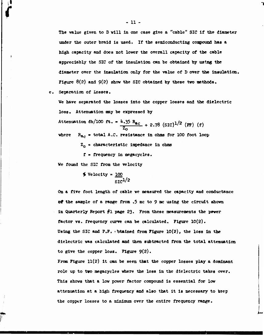
1
{ « 11 -
The value given to D vlll in one case give a "cable" SIC if the diameter
under the outer braid is used. If the semiconducting compound has a
high capacity and does not lover the overall capacity of the cable
appreciably the SIC of the insulation can be obtained by using the
diameter over the insulation only for the value of 0 over the insulation.
Figure 8(2) and 9(2) show the SIC obtained by these tvo methods.
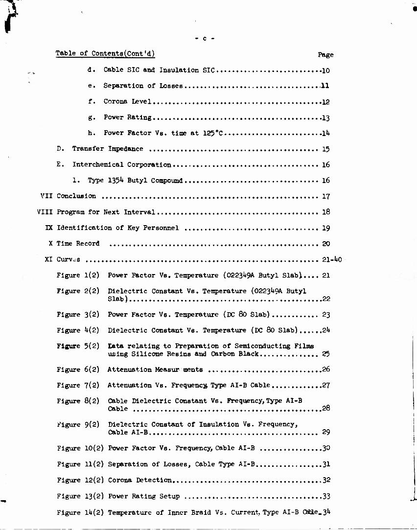
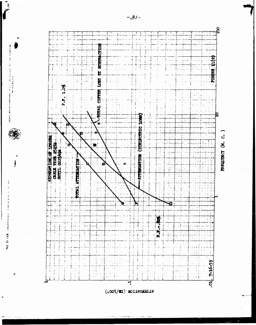
Separation of Losses.
We have separated the losses into the copper losses and the dielectric
loss. Attenuation may be expressed by
Attenuation db/100 ft. . kg ^ + ^ (gic)l/2 {pr) (f)
vhere R&c - total A.C. resistance in ohms for 100 foot loop
ZQ • characteristic impedance in ohms
f • frequency in megacycles.
We found the SIC from the velocity
$ Velocity » 100 SIC1/*
On a five foot length of cable ve measured the capacity and conductance
off the sample of a range from .5 mc to 9 mc using the circuit shown
in Quarterly Report #1 page 23. From these measurements the prwer
factor vs. frequency curve can be calculated. Figure 10(2).
Using the SIC and P.F. • btained from Figure 10(2), the loss in the
dielectric was calculated and then subtracted from the total attenuation
to give the copper loss. Figure 9(2).
From Figure 11(2) it can be seen that the copper losses play a dominant
role up to two megacycles where the loss in the dielectric takes over.
This shows that a low power factor compound is essential for low
attenuation at a high frequency and also that it Is necessary to keep
the copper losses to a minimum over the entire frequency range.

I «. 12 -
f. Corona Level
Three five foot sections were cut from the reel and tested.
Figure 12(2) shows the apparatus used In testing these cables.
Sample
A
B
C
Average
Initial Corona Volt
10,500
13,500
13,500
12,500
Extinction Corona Volt
Initial Volt Extinction Volt
1U,850 12,000
19,100 16,200
19,100 12,000
17,700 13,500
8,500
11,500
8,500
9,500
These are the actual corona values of the completed cable. It should
be pointed out that these are ras voltages and If corrected to *>eak
values.
Peak Corona
Sample
A
B
C
Average
A five foot sample was cut from a piece of cable which had a heat cycle
with up to l68*F on the conductor, 185 amps for 12 hours.
Initial Volt (peak) Extinction Volt (peak)
19,100 12,000
In view of these results we are doubtful about the elimination of the
Inner semiconducting compound. A check Is being made as to where the
corona occurs.
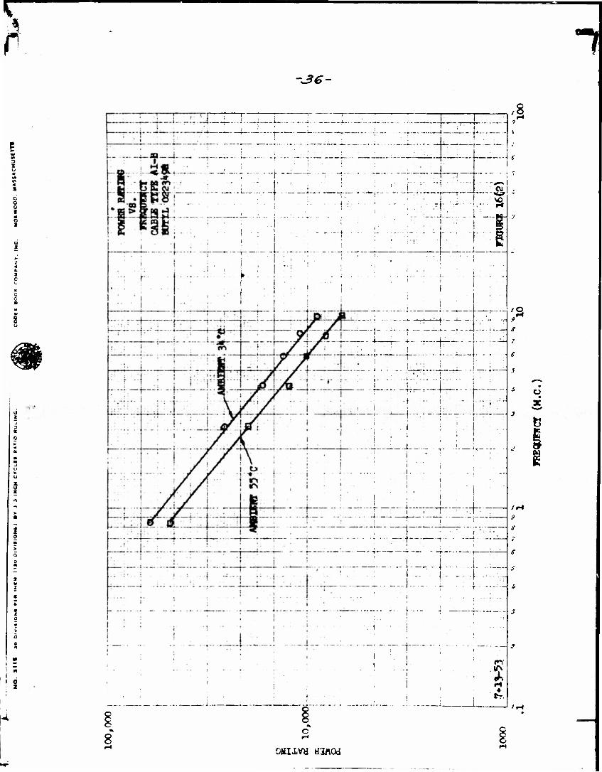
Power Rating
Figure 13(2) shows the test setup for determining the power rating of
Type AI-B cable. A 17-1/2 foot sample was used for the test. The
current was supplied by a low voltage current transformer and the power
dissipated in the cable measured as Indicated In the drawing. Several
different currents were passed along the inner conductor and back on

i - 13 -
the outer conductor. The ambient, power consumed, D.C. resistance of
the inner conductor vere measured. From the use of the variation in
resistance vith temperature, the temperature of the inner braid
conductor could be calculated. Figure lk(2). Figure 15(2) shows
the 60 cycle watts/ft. dissipated in the cable versus the temperature
on the inner conductor at 3U*C ambient. From this curve a dissipation
of 19.2 watts/ft. will give a 125*C temperature on the Inner conductor
in a 3U*C ambient. If the ambient is increased to 55*C a dissipation
of only lk.& watts/ft. would give a 125*C temperature on the inner
conductor of the cable. To figure the power rating of the cable at the
operating frequencies the following method was used. It has been
established that a 19.2 watts/ft. dissipation will give 125°C on the
center conductor at 3^'C ambient. Therefore, this must be also true
at the operating frequencies. From Figure 7(2) the attenuation can be
determined,
a(db/l00 ft.) - 10 log10 Lj^ (i)
•*°* [$ - fSt <« P In - P out - 1900 (3)
Pin - ^ p-r— - 1900 (U) Antilogjjj
Pin - ^ (5)
1 i ID Antilog ~ Ur
and equation (5) will express the power input that will give a 125 *C
temperature on the inner conductor at 35*C for a given attenuation.
Figuring a .002 duty cycle would mean that the average of 20^000 watts
was dissipated. Hence if a weighted attenuation could be obtained for
the particular waveform used, one would merely pick out the intersection

12 { -14-
of the frequency of the weighted attenuation and the 20,000 watts maximum.
If this fell below 19.2 watts/ft., the cable could be successfully operated.
To determine the rating for an ambient of 55*C a proportion was set up.
Temp, rise (A) Temp, rise (B) Watts/ft. (A) ' watts/ft. (B)
So for an ambient of 55"C with a maximum hot spot temperature of 125*C
on the conductor
90*C 70*C 192 watts/ft. * X watts/ft.
X - (70}U?-g? 90
X - l^.S watts/ft.
Thus 1U.8 watts/ft. dissipation will give a 125 *C temperature on the
center conductor. Figure 16(2) shows the power rating at a 3k*C and a
55*C ambient. The next step in this program is to determine a weighted
average attenuation so that the frequency at which the total weighted
attenuation is applied can he found. Knowing this the power rating of
the cable can be determined by use of Figure 16(2). We are in the
process of determining this weighted attenuation,
h. Power Factor Vs. Time at 125*C.
A short length of cable was placed in an oven at 125*C and the power
factor taken over a period of 18 days, Figure 17(2). This shows a
decrease for about 10 days, when It levels off. At the end of 15 days
the Jacket cracked and was noted to be very brittle. The Butyl appeared
to be in very good condition. The cable was removed and after standing
in air for a period of 8 days still had a power factor of .7$ at .5 mc.
This indicated that the cure time of the Butyl was not sufficient and
should be increased to give a lower power factor compound. The physicals
of this cable are as follows.
KSH

f - 15 -
0223^ Butyl Insulation
Tensile #/In.c Elongation (2H)
Unaged 715 ll.U
Aged Ik days at 125 "C 6U2 7.05
Semiconducting Compound
Tensile #frn? Elongation (2")
Unaged 1320 7.7
Aged Ik days at 125*C 1192 k.9
Overall Jacket
Tensile #/ln.2
Unaged 1*310
Aged Ik days at 125*C Brittle and cracked
Elongation (2")
13.3
From these results it appears that the Butyl vill vork at 125*C and also
the semiconducting compound. The Jacket however vill not withstand this
temperature.
D. Transfer Impedance
Some work has been done in conjunction with Mr. Spergel of Squier Laboratories.
We have tested several cables using the circuits shown in Figure 18(2) and 19(2).
We have on order some copper tubes with thin walls that we will be able to check
our apparatus. The complete results are being held until these tubes are obtained
and the apparatus is found to be correct. All connections are made with type &Jk
General Radio connectors. The cable is enclosed in a copper tube (I.D. » 2")
as shown and provisions made for termination of the cable with 50 ohms. The pipe
is broken at each end. First to allow the signal to be fed in, and at the other
end to allow the 1 ohm resistor to be Inserted in the circuit. A more detailed
description and expVanatlon will be included In the next report when we will have
data on the copper tubes which can be used as a standard reference. (See Bell
Laboratory Report. File 36676-5 Sept. 23, 19^-3^30-EFV-HE for a more detailed
discussion.)

» *
{ - 16 -
E. Interchemical Corporation.
Type 1351* Compound.
We have received permission to try type 1351* Butyl compound developed by
Interchemical Corporation. Dr. Radl of Interchemical has sent the formulation
of this compound to The Okonlte Company and ve are planning to use the compound
on Type 2515 cable, 4 25 ohms, 15 KV, 10 megawatt cable. This order Is being
entered and will be In the factory as soon as the materials for the compound have
been obtained.

f - 17 -
VII CONCIUSIONS
1. It has been decided to use conducting paint of both sides of all slabs to be
tested.
2. The SIC of type 0223^9* Butyl rubber Is 3.55 at 1.5 nc. (From cable AI-B)
3. Type 052153E Semiconducting Butyl appears rery good at 125 *C and 0*F.
h. Corona level of cable AI-B Is on borderline.
5. Type O223U9A Butyl Is O.K. In 125* Test after lk days.
6. Okocord Jacket no good at 125*C
7. Type AI-B cable power rating appears sufficient for 10 megavatt rating.
8. Type 2515 cable to be made with Interchemlcal type 1351* Butyl compound.

f - 13 -
Vin PROGRAM FOR NEXT INTERVAL
1. Tests on experimental pulse cables when completed.
2. Tests on 15 mil copper tubing with transfer i apedance apparatus.
3. Enter order for type 1215 cable made with 0223^9-A Butyl.
U. Enter order using Type 135^ Interchemlcal Compound on Type 2515 cable,
5. Check cold temperature effect on Butyl.
6. Check on semiconducting compound for ellastic rubber.
7. Investigate a Butyl type Jacket material.

t - 19 -
IX IEENTglCATIOfl fiF KEY PERSONNEL
(See Quarterly Report No. 1)
Morris Weldetein (Summer Eelp)
Graduated from N. Y. U. 1937 B.S, in Physics and Math.
Graduated from N. Y. U. 19U0 M.S. In Physics.
Teacher of High School Physics and other Sciences for 15 years.
Teacher of College Physics (Evening) for 8 years.

- 20 -
X TIME RECORD
Time "Spent on Contract to Date
F. H. Goodlng 1U9 hours
E. B. Slade 21 hours
R. G. Feller U19 hours
Laboratory Technicians 458 hours

1
*•*,,
I
-Zl- 1
i kiO^)Vi ttiflCd

1\
o z
.* CO
/:

fi
I
o o I,
r 4~
{%) aouvi aswod

-24- 1
I :'-::-
t
|
[• :"'• 1 • •
1" •- • :••---
i !
l
1
i
! ••• ':•• • r- L 1
i-; • 1 ;
...'.-. • • • i • *
• -r-n..-
. .. 1. .
>
_ i ; • ! • ! i :
1 t :. j . If i ... .. . t — '••:•••:•
:;;!::•
-•:-—•
1
i •
i J—,. .. .1. — U- - -
... 1 . i
•::j: ,
FBE , ... i. - • • • • i '•• :fi
—•-—. i . • •1
•t :- i .
i ' i "I ,i. : ..:-...._
I 1 '
• ~i • • • FI ——-
i
i ' ! : ! : IB 8.7 : :• 1 : I. . i-
*— •
' '• - I
... T .. 1
:!:•;; l-.i- ... i 1
i 1- . .; 1 * i •'
.... i . ::.• .::: 1 :
::•!:: 3
.. . i . j ; ;• i
i. .... . ...... .. 1 1 • l.--r-... i • I
i 1 ! j .........
i *
1
: •:: I :: •; •" • • i • •
•;;-•[••
u
r ;• . 1
;•::;:;: h;-:-S " •j ! "
...: . 1
1 . ! .
: •:}••.. 1 • ;::;tfi::
• :
i
i
i :
I :
•. • j • 1 •,' •
r
; : • • . . . 1 ... *
!
1 : i .... ..j. ... .
1
•...} .. ... 1 ... . . .*.... - i . . .
" i.'
1 .
' * i . i.. •..'. '.. :: :j:. :
u 1 i ..;. 1
...:..:. j ... ".'"c:". i .
--j- .... i''.'' ~~—.—• ~
.' ; :;' •
9
> ! > I
i •
: • :
j :*|f* . • 1.
Sfe
6 *° i
1
\ ... -;•••••- 1.'":
• 1 - • :"-:l:-::; § 4^-" :. •. 1 •' • —
«,« : J ; .. .....—
W^ ......... i
:: :j -••'•• •
::::]::.
—'•—
•
...: .. ...-: ... • • • j . • •
. . .( ....... 1 |
1
j ..:::...:. .:._;_...
i . .
; ;|.:: :-l::-i
•
•1.
j m ..::.;:.... :...:.:..
• • • i • - •
rrrrrr: 1 \ i • - j • o
! :. ;;:..• :. ."•
- . , • . :!:••!
::: I.. •••\r::
......:.:. • r:;;• • •,
IfN
:rr:L:ij 1 *-
i
'..': i i
i
••;•; 1 ..... .};•:: :::•:•.
* • •
i
i i
1 1
• : : •'• ! !
1. :
.. -t-.... . +m~ ...
.;::f:::.
•
: I :^- i : '
.. _..: ..:...:. ......._ •.....„:..- :-••-•—
•':;:•
: :!:TTTj
•.::! r,: r -.-•...,
— -1 ••• ... i«...
1 j . f
•
1
i
..... .
i I
i : i i - - *
:: ; • 1 :....(
*. 1 .:.;:..; . • • I • • •
... i..'.. . m .......
1 . • . .
..:._.. j i i
! • ..;' , :':T~'.'
:r\d* 1. i
... .1 i
{- i.
I
1
... ...j. 1 I
1 ..!.:: : O
lf\ CJ

BY - 25 -
DATA OOUCBOnVQ THE PRKfeAlftTICft OF 6BM1-C0NDUCTI2W FltMS tfSINO SILICONE RESINS AND CARBON BIACK
1 «^s
Mixtures using DC 996 and DC 803 vlth Shavinigan acetylene black (Shawlnigan of Canada, Ltd.) have been made. The black la stirred Into the resin by hand for best results. Glass slides 1" x 2" x 1/32" were dipped In the solution, air dryed, and cured one hour at 250*C. Resistance of the film vas measured between silver strips painted around the slides and spaced 1" apart.
Resin
DC 996 DC 996
DC 803 DC 803 DC 803 DC 803 DC 803 DC 803 DC 803
DC 996 DC 996
DC 803 DC 803 DC 803 DC 803
It Is evident that the Shawlnigan acetylene black Is the best for low resistance coatings. There are Indications that the resistance will Increase somewhat vlth aging at high temperature, but apparently changes little when subjected to high relative humidity conditions. There are little data to substantiate these conclu- sions, however. If small changes in resistance are Important, the particular formulation should be checked. The resistance will also be affected by the type and amount of mixing used. A well mixed solution will have a higher resistance than one that has the carbon stirred In by hand.
The physical properties of the films are good. Most of them are bard and tough.
Pts. of Black Resistance per 100 pts. between electrodes resin solids In ohms
10 1000 10 i»50
20 38U 20 270 10 333 10 329 5 vno 5 3330 *j 2320
onlzed graphite:
20 Infinite 20 n
10 10.2 x lo£ 1.5 x 10° 10
20 22000 20 \yxx>
( i
Figure 5(2)

-26-
Co
to
wrwofincrt mfisdez/iENrs
Atritffil £»D/o /Jut//** —w
X 4£*£Ml £ADJ»
TIP* 7e** //re r"3£
T
to //*>*)££ * (e)
THE OKONITE COMPANY AND TMC OKONITE- CALLENDER CABLE CO. INC.
PASSAJC. N. J.. U. S. A.
rxxnxrsrm. SCALE
AM:
REVISIONS
DRAWING NO.
?
ft r» in m

t t
L
-27- 1 ":: • r 11;. : r *i=i=f; 4 .T- :- : -:•
rr ':;-=!"•: • />•..!.
1 • : ! : " . *i: : : !:.:;• *. ;;. ;..
1 -?- • • r - \ * J** :. .1 :.: • • • ..... .... • .-.:. 1 . . 1 ;.-v
.... t ..... . t-F: • : : : : • • : ! : ?.-.:—~'~
•:.:
; i . • : ;:•:•: i , : •
•;: : . ...... ,. • • ' |
i ; ': - i':*: • :i:-"i •:; . : . : r-:-:•_::•. . ••
1 • •
1 • :::;•: ' ~ ,*. ~*.Z '. ' ~-Jr yil
.1. . •:•-- -
._.... :_•_:_;•• ; • ii_ . :•;. . :... •-—'-
•"--•i
':- i j . : ••1-»--. —- •- -; --: • ---••
34 ~i::
H::.T":" ——_. ---• :::.]V_,.: 4.:;,....
' !' - '
• ••'.
; . ." •• \ -
7Z-. i i ; h-"f ;•- ~[T.T:' 13 ^
• -.; ..j :. •" -: ;. r" : ; :.: .':
....: •-- i • •
• i-\-j i •*;:.:.: . •; ... J;.. __: : —i r:
.... - .; .. . . ... 1 .
. i . . . ..
--- ... t....
. ;•:: :- 1 .V . 1 .
1
..... .;..ds^ ;.. . _T
1 •--i-if^L ^. . 1 . t . • • — •- zL-fc-.rr 1 . . 1 i ....!. ._ —! r_-t
•
1
1
j '
1
'•|:^
fiii
'."IX r "t"+ r-'t" "H .! i..... .;:..; :.. ;__,... 4 ...
.....
• •
•—i •
.. • 1
i 1
. ._; -( ^ .-^_—
TTi —*- > > Ml IT;
•p"i;-
i I
! j ;" | —r -)—•—i—
: i
•
i
- 1
jji .LilL TM
1 ! •
; i i;
IEIT ! i { ! i ' '
i >
ifFF 'fiNT*"' 1" ' i 1 VI ! 1
... .j ; •;. ; ...... >; . .
4 .. _ » '••i • :i ::•. .. . .
•••j . ... «
: .Jfc t . :'. : —:
. . j..
r : . : i
—_ • K. — m~ 1 -r—
i
—4
. •:.:.[
! 1 T •"
— . • . — *sr
1!J": 1 = : : j •;
-r:- :..._ -~\ : : ! •.:.l, i 1
: : ' ; '. ~
11 ;.; : .-. 1 IT : - ••'••
...._. '•••Y\\ j •'
":~~r-7':'jy:'""~:M j: \ i : • . I : 1
.11
••;• 1 •• r _'•• j • : . : . .
'•-- '•}•
-•'!•; • ': '• : ! : r~~
- i • • -• i -1: ....:. \: ; • • -. t r .. : 1.: -t
1 • 1
:;::;}•: j .•,:•-;-•::• ::.!••' !
". :".: • : ::: _r r~ .?...!.. 1 . . ;. . , ......
'•'•'••' '- .'-_*_::rz . . . j .
• • • - i :.!.• ; . • : : :.
...i i ; ...:.:.._'_ 2:.. ... .. --1 1
" • • 1
• 1
— r — •
... , ... -! - 4 _
. j . — . — ;- !'"!' i , I • -t——t—
_ . ._l
1 1
1
!' ! i . -« -
.;.... i;. - - - 1 -I -,-—.-• ,
1
• I
i •• i
1
• 1
1
• • 1
•i • 1
• !•
1
• • 1 1 1
i ' ' 1 1..'. :'"..'.
Itfi i
' , i i --. •
1
1 * I f
••—,—1 1 ! ! I '
-•—«- - T
-r -M i • - •
i • • t ...j •
t • 1
.. .1 |
ijii".:
j H^= .;: :..;..• rrr
* • i •
" , 1 ;
1 • • - i • 1 ; j *
-• *-]-} r I 1 - ! '••
1 ' i
——,i — — 1..7 1 0 L.
!l ........j 1 ' L.'H
1 .
(,ooT/aa)
r •aa- 1 I j i
•j" • •
i
i i
i
i ••"::•'• i
• I
1 • '••
I :
l •:
i
i : 1
! : '1 :••• I
1 ' •j .•.:...
| •:••:
:.!.
-|—TT'... .
i
' . j . ... ( — • • ;
i" i
: : I
i -:"J .° j' :• 1 i JO
I ;
1 "": i
! :..:i-r 1 ;
j | \'. ••'•'
- •-- ;-•:
1 •: •!
t : W -} • • • •: I. : ...:; .1 :..
• -I- ! •: 1
! 1 .
:ft"!--: a.
' !| I I'
i : X - _
i • • ii
:•- ! - ; • i . 1 • •!• 1 " : • | . : » •i
i
• h;: 1 i
i
V i ; , ,.r. .....
1. ' 1 - ..
i . • I i
Lit...!-: : 1
... i::: r i
..:,:..:..:... It 1 i 1 : " i ...
i
•;:!:.-
•
•:'.--|::-; i i • •!• ! , . 1
": ' 1'
•1 •'
: 1 1
1 i 1 • . 1 • 1
i 1 1 •i " J • . :: .: ! . i
1 : i i...
1 1 . . ....
t i .. i .. i . ... .....
• 1
" i •;
J, |
.; •' •
. • i
1 ;' . ;" *
• i'
I •••.-; -.-•-.••
I | :. 1 - . ,
• •
.... •. **i.:•:
i
1 » M <
?9 r*
H
{I"
i :
i
T ! .
.......1 •..:.. ' ! - : •
• ' - • •
,:•; 1 r;:;j:'::
•.:: 1;'.' : - 4 • • • •
• I :
: j: .
,
M
e jf ' :: !• . .
• •• 'j T::;;
•
. i . . .
"'
.:,:.|:.H: i
:. ; ': •
tp\
a i'
-- 1
:;. t
•
< i. :.. 1
........ ; J; : .; ' . .... ( . i
i - : •.'
1
:.• : !..: I . ;::.: ....,::.. • ; I
! • ,1.1 ::, •;. . ..: .
i .:.:!::; -*
1 : : 1 1 •
• t •:::::
..:::... i
•
. • _ I
• : '• t :. 1
• 1 i
i
i
.... . J -: :::
i
• i
i
i
: 1 i ' j ; T f
i i
.... f*i
i
! i
1
J j
• •- • !
i. \ i
• • l
r ..... j
j
; 1-:-: j 1 1
! .._...: '•••' \
;;-f-:f:
• i « ... . .. i
i . i.
" 1
i
i i i I
j
• \i
/I i i
.;...,:..,::,., 1 <
•--»----
I
. . . i rvj
j. ... . j i • rj-.-l
1 •
/ 1 1 i ; ;
. . J 1 i
i 1 1
• • 1 • » . . I
I ! • J '
. O .. i • ! 1 ! j • i j • ! :
j i-m "i . . t .. w\
* i i 1 :: J
:
1 i »
i i
1
cr
1
. ! Xtr
.. . j.
. ; j
1 '"*'•' 1 1
i. ; ; i
• : -K .• i - • •u.:..i. :. |. ;::;.. n4#
o
r<o ro m iMVXSMOO ciuiDTina

-29-
m
iKViswz oiaiLJiaia

(
i
o
-30- 1 \. ..: .
1 1 - t
l .. .. •• ':.'
1 : 1 : .:' 1 . . I.:.
: cO - •• . | - --;
! • i • -:••,
I ' i
t"" i i. 1 ,=
i i .".*.,*
j... • • ; •
•. .. J... : 1
t : j : •: . •: -•
: !•.:.
v :-::!:'-
• • * t -
•: i :: .. t 1 '
• :•- j - r • :-.. i-: .:-•--] --
i
i . i
: i ':. i
: 1 ! 1
j _ ; i •:.
• ^f . -.._.*_-.. .......... i • • i 1
: 1 i I
1..-..::.
. •'• tu
• : i i :"
i.....' . . 1:
^1'":;. •-•-
--. •:-'
i i ........
• ! i 1 j :
• - J - • • j ." : i ; 1 : . _„-!_:.
•--:•-•-•• ii|
!
I
"i: .....
i
: i' ' .... j. _. .
": 1 •
" :
( : •- i •
......... ....:... 1 i .
1 :'!"r': .'i
-'.-"::•-
!
i I !
•; ! • '
• 1 ... : ...
• • • i • • •
i
... — r
1 : • 1 1 ': '
:. .:
i
U- 1.
• :f~ — ,f . •: :
i . . - 1 : i : i : • '..:':':
ft *'"••
< i J • j
:. :-.:. 1 ..
..... ...
....
.... ;. .. !
1 j .:...... i', r»t' T~
1 9 ta 1
... : .' i •
•
; • •
1
i ..
... 1.:::
...... . . . a . .
.::;• : ^1
ft 9
air, KM.... M • ' '
... i'. 1 :
• : ?*
: : ...'.._.
« \:
1 A,'. ! • j • • '
• . • I
•:: • •
1
Sli- '. \. 1 1
.:.:.... .!.. :
1 .:.., :.... .... r .....
1
_.-,i_:,i~ _::.;.....
:. i ir i i
• ••:---;
::.i::. ...:..:. y; 1 i
\ i r
• i
... ... :. • 1 • • • i
.. |. .. ''... \
t;::!;::;
' i ."• - .' : • '•:.' • i i V . •: I:'. '. 1.
• • 1 • • • :.:;)::::
r •: ;- ; ! • i
u|- i •
i 1 •i
i
;: 1 '• \
!
1 : . |- •. ;:!.-: 1 - 1 ! j. ... ...........
• : 1
t
• :.-." -j
1
...L:..j .... • -1 •
i 1
\ : f \' i
•:L.i:-::::: .. i •. ••
••::: i
:H CVJ
1 ! i
i : 1
t
; I
-•-'.-•
i
i
... .: • 1 • :\ 1 • 1 ;. .......
i
1 !
1 ,.....T ,.,:4 1
i :
•'..'!:. j . \ ...... ^ . ... ::T.::T
i. :: .:: ;.:.:....[ : ....; f
! • !:• •! 1 p
;i::-r i [ i. *' • : : .
1 :•.::. I i 1 - :•:::•
;i-S 1
t
I....: ! i
:. i
• J
i
• 1
r r
1 U .-::..;.-:-..! j.. .LiK- ::r:;.|::-:r vl::.-^::: j :•.::. . |. ' o - m—L
« X
CVI d) UOJiVi iQAOd
f -31- 1
o
x .;__!_-
: ;: I , ••: !--• •)
- !..:. i 1
I ' ! ! 8
•r 1—
i I
«—:--j ..
OJ
(^OOX/fld) Moixvnuaj.lv

r r°
t°
-3P-
CO&OMA '. DETECT/OA/
GSgam roHTLAT/o* T&3T £QU'PM&#T
rye "?
pa r tire*-
HErWo*-* MFtr£.. Co. GAtedXIutU*
JLEBVS
1
iO
THE OKONITE COMPANY AMO THE OKOMITE - CALLENOER CABLE CO. INC
PASSAIC N. J.. USA.
DATK on. CM.
P'MW SCALE m APP.
£Ux /2 {2)
REVISIONS
DRAWING NO.
Q-3>93Q

it
\>o
<o
o
1 -33-
£QM& &ATM£r. SETUP
AMMSJ-EK^
** »**^ ct TWfO*#SA>.
\
44° » MA*.
i H£*
wrr**r**-
&LZ6JMZMA
z£^:rfci
/LS3/JTA*CM &XJjO(r*
r#4M*c cauelJSJ
4 ± -i- c*e>i* J- a
F/tr. (3 (2)
THE OKONITE COMPANY AND THE OKOWTE -CALLEHDER CABLE CO. INC.
PASSAIC N. J.. U. S. A.
UZSxJMZSl SCALE
•&JW |CH.
TR.
APP.
REVISIONS DRAWING N

f
18
-34- i 1 - 1 • •
}• ••; •• i
.(.:. ; t • 1 . . 1 I:. .... I...
::.. J:.. '. .. i.. . i.
18 1
i:j i j • 1. 1 • • • : i:.:k:
• • . . j
........ i i ...
1
1 . 1 .
1 .: : . . i : :: . | .! . • J:.: ... , • '
• i
" : ".:'"' i
••j !1 L
.;; i.'::' - • 1
:: .j ;r; . :. -
• •
•r::r''
i
t - > • ^
' .! 1 • : i • i
i
• i • .:::!::. 1 '
1 •
... |.... i •
l •
•::•: — * i
• ••i.-fi
i
i . !
X^ <!\j""':
1 . .JLJ.; !
L '. diii o
i
• '
t •' -•Net" -:•::-:: ._ :_...
. • . i •:.. t
1 . .
!~~~; \TT" — •----
i ..;•:.
' i I:.:;.;::-:.
.. i
r ";-*>-, ....:—. ._. 4 • --- — •:•-•- ::.:i..
• j _...:.:.:. ::;r::- .* ir::- ... i . ;i.
•::;T'~ --::::;- .:.::;.... l .: •
::::j.::: • • • • i * • <
.:..:...: ! *. '.
.:. 1 . i . . r
• | •
1... • • • t
- - i - •
: j 1
:....i...j ::-:.j:rf: ^kJ ' "
: . 1 . •- i •
i i :.' .
i
......... .... j. ..
1 '•'- • .. J:: .
—-'•—- ;'..;;:.. \ '•
. .. i
i -
. i • : !... •
1 . - - .
!TL • 1 ;'. i:r:
.. .,. .. :.::f..:: ::r\ ••• ;!::i-.;; g
. i ...
:::.!:. :i ' . . 4. '.
i. •\\\-\\\
.... i . .:)::;:
:;!:i-; ..*'!' * «H
• t •
"•'•I.'
.:•)
:r::i:-.: . • . 1 ...
:: i. '
.: .i: • • . i...
" i
i 4 ...
........ .,....::;:; ;:.r.| .:.:::
:' .1 •
• • 1 • • • •:'•::
°\ - I. . .
V::i:::: .','.' \~ '. . ".' • j.
. ...'. |
... , . |
•\ 1 -•
. i. .: " I.."-
. .' 1 . . .
| ••:.;•• 1 • . . ....!. •
•—• -•f:\::r
,:;|.., .,..,...
• t-
. ::!:;:! :.:: i •: •:
^.... .*..... *.. i
:i'.: ; ; • j • -
•:::.::
• 1 1 . :•. i"!:
. t . . . . -;P#r- : .;:
i-' *' * \
L... J .
i - • •.' i.. ::_:•. 1 .. i —
i
«*
...:.:.. . ....'::' _ .-1 -:-::•'•
» - -—f—— .
t • •
• I • • • 1 ; ; • • . . . 1 . .
.1 * '. w $< ! ".:• I lM
B ^ If) 5
p :•• • :
: . : 1 •:• • ::;. .. . . . . i
T-::.-T:
•l1 3 : - ,.,,...... -,.-,,,...,,.
• 1 :
i • • t rla*i 4 t
• ! • : 1 i • -
. I -:• I • ' . -
:~L"T i
:..;..:.. : . 1
:. : :|
... , ..... ... :.
1
I ; 1 1 , i • i:.. I ••••;• !•••!•=;
..::..::. . -:-|:-: . '. 1
1
• - 1
t • • •
.1 .: jr: :»
w* 1 •:..::: i .•:..:: ..." .:..
• . I •::. i -: [ • • . 1 1 • i
.: i '.: '.1.:::
i }
i i
t
1 -
1
1
1
. 1 i •
I
i »
I
.: ..:. . ..... • 1 :.
•j
•::::-|-:.:--- •
;:::.):::;::• .
... t, . .
:• :.-:•
:..;..-
g
8 8 (zivHOiiiiaD) sszuom

. '
! I
*_*M-'
i 0
(MVH0IXM2D) saaaofl
-3€-
,8 —r
i .. . —* i
t—~—_-•• -•--•-••• -—•
i ••! ': ':
. i : i •'_.:_,
J~
...:J::..;..Z] i
I"J...
i
i
i...'. i
-vf-
T"
H •
7
/r-J
DMIIVH tf3M0d

-^7- 1 • : .
i
...... 1 .-••
i -
i
. • j:.::: .:• .. ....:. .:X::'.
• • • r •; ' . i i '
,. .. t.. "•i:-"'
T-TTj. ::. &
1 .::!.;. i O
1 • ;
:... .j. .. i: .:. . . I i t .' : .
••:. ......... _
.....—
1 •:.•: 1. :•'
.. —i—.^
V:\-m
1
t ft
< B ...:;..;.
, .. 1
-•'-'• '• :•:••;••:
— !:.• • < a
3 if ; •
'! ! : ; :•:- •-•'••
, • •'. •
.._.;...: : ..j :.
at! ... ,::. .
• . .: •
•
'-;-;:-•• ........
7
"i
i • *' • • •
2 3 -4 ..i.-i..:i ...::-.'".. 1 . i. _..; .. ::-;-L;: ;-:rrir?:- A ': • i ! : ,; 1 , .
.... . - \f\
*
• :
• ;• • 1. i
: I i j ; ;
1
..___
1
——I •••i
i ... ....;...
••;.:: i • •
ri";T"""-
u
• . i j . 1 i 1'
—it
..".*. . < '-I-:- • 1
••T 1 ..... , "•!•:
-•-•--
........
? i 1
• i
: i . 4 . . .
i
1 : 1
•":. 1 ^ i
1
t '..'..It'.'-. : :
. • t - • .
HI 1 1 . •
1
i
1
• i
•jr
1 V *•* • . : *
- •
...-,.... ;;.;::;;
y -**'
'.
1 •v. *::.1 ... : -.
|o
j •. : ....
'. : 1 : i l
f
\
i tX '' '
-..hi; Li.iil::i:
o B -1....
." i . i
• ••!:-:• • • t - -
' : I .
1 .
1
- 1 •.'::! .'
. • i 1 '! ... ..... • ' ', • \ \ * * -
3 s 0 •
i
....i. ..
Q •• IA J .
.:.;. • • • • r • • •
r:..!:... i - •
!.. ::i • . ; -. i N
i • i
• • i. • i :
'
•(•/•:
m ......... :T.':;-~- , . . ^4- . .— ! l'. 'A.'. n
• < . ... ..
•••"J.:." r...
i
I r ' ..._; . .
• '••'••• Jt,\ .'.ri.. ::
: 1 , i r : J i
i ;
.;.... : ;
1
...... ... .. . ;. .. I ' M '
....: .... ; \ 1
- •••:.~- ...::.:.. -•—;-•'
X
• >
•
: • r ' ; ••
/ / <:..
:•• ..:; .
i:;;r.i|-:H:it:
< 0
.:;.... . . . : ': =
...; . - :::-• :..;..: —^••i-
c 2
.. .;. . . :
1 . '•'•/• /•:••• ••"- -j -.--—TT:-
i ' i • ' ' 1 ' "' i - - . •
. . . .i i>^* /' ' \ 1 I ...... i •-« 1 -• .
'.' ..:•.{.:;: i .
• • " • I 1
:':"'.'...•:
. '.- : • s^ / 1
. 1
1 t ' i
, 1 " ." •" !
1 ...
CM ao^va^aawod Jiuoaad

f
*o
o
'33-
Zotfi T£sr <r/etd/r#/
3*A r. S*/to0CT&£
d9/>/>££ fs/>£
y'/f£j/9BL£
1 ajc. l-ljj,
Or
£J?4£rt 4 *:J/>£e //£7Zeaay*£ I/OLT.
£> f/64*E & (£
THE OKONITE COMPANY AND TNC OKONITC-CALLENDEft CABLE CO. IMC
PASSAJC N. J. U. S. A.
w?rmaFa.t.m SCALE
[CM*- **
m APP.
REVISIONS
•jFSVTa

i o
Jo
-39-
:B r£5r oetMT *?
&A
<mnnr\
[*J£. Lk
ri
&£rtE£#L e/VDJ0 /330* &&£>&£ 43C. ffi^Erf O50.50 i/#e//t3L& fiTTS*.
*LL ££$/6T0£$ *££ &£*£e/9L Pffoia
\o
i
/:/6<J*£ J<f {£)
THE OKONITE COMPANY AND THE OKONITE-CALLENOEK CABLE CO. INC.
PASSAJC N. J.. USA.
DATgf-//-/-3 jscAuf^"
CH.
TR.
APP.
ftSVMtONS
DRAWING NO.

ko -
( XII REFERENCES f '
n
1. Flexible Coaxial loner Conductors and Braided Outer Conductors.
Bell Telephone laboratories, Inc., May 20, 19U3
2. Reports from Airtron, Inc. on Contract W-33-038 AC 17153 Interim Report III.
3. Dow Corning Bulletin. Technical Data DC 80 Slllcone Rubber Bulletin 9-325,
March 1953.
k. Bell Laboratories Report. Crosstalk Between Coaxials. File 36676-5,
September 23, 191*6 - 3U30 - EFV-HH