Embed Size (px)
Citation preview

HIGH PRESSURE BOILERS
� High Pressure Boiler, P > 60 bar
� Critical Pressure Boiler, P = 221.2 bar
� Super Critical Pressure Boiler, P > 221.2 bar
� Sub Critical Boiler P < 221.2 bar generally in
between 130 to 180 bar
� Low Capacity Boiler Ms = 4000 to 6000 kg/hr
� Heavy Duty boiler Ms > 100000 kg/hr
ww
w.jo
sh
ika
nd
arp
.we
bs.c
om
12/24/2014 12:24:23 PM

DEPENDING ON TYPE OF FIRING ADOPTED
IN BOILERS THEY CAN BE CLASSIFIED AS
� Stoker fired
� Pulverized coal fired
� Down shot fired
� Fluidized bed boilers
� Cyclone fired
� Chemical recovery boilers
ww
w.jo
sh
ika
nd
arp
.we
bs.c
om
12/24/2014 12:24:23 PM

VARIOUS TYPES OF ARRANGEMENT ARE USED BY DESIGNERS IN
DESIGNING THE BOILER FOR MEETING THE END REQUIREMENT.
HENCE BOILERS ARE CLASSIFIED BASED ON THE ARRANGEMENT AS:
� Top supported boilers
� Bottom supported
� Package boilers
� Field erected boilers
� Drum type boilers
� Single drum
� Bi drum
� Three drums, but these are presently out of use
� Tower type or single pass
� Close coupled
� Two pass boilers
ww
w.jo
sh
ika
nd
arp
.we
bs.c
om
12/24/2014 12:24:23 PM

ACCORDING THE "ASME BOILER AND PRESSURE
VESSEL CODE" BOILERS MAY BE CLASSIFIED AS
� Section I Power Boilers - process boilers, power boilers and high pressure boilers
boilers in which steam or other vapor is generated at a pressures exceeding 15 psig
high temperature water boilers intended for operation at pressures exceeding 160 psig and or temperatures exceeding 250 degrees F
� Section IV Heating Boilers - commercial boilers, industrial boilers, heating boilers, low pressure boilers
boilers in which steam or other vapor is generated at a pressures not exceeding 15 psig
� high temperature water boilers intended for operation at pressures not exceeding 160 psig and or temperatures exceeding 250 degrees F
ww
w.jo
sh
ika
nd
arp
.we
bs.c
om
12/24/2014 12:24:23 PM

CHARACTERISTICS OF HIGH PRESSURE
BOILER
� Necessity of forced circulation for water
� Pressurized combustion
� Increased heat transfer area – water tubes
� Improved medium heating
ww
w.jo
sh
ika
nd
arp
.we
bs.c
om
12/24/2014 12:24:23 PM

ADVANTAGES OF HIGH PRESSURE
BOILERS
� The different advantages of high pressure boilers are listed below :
1. The tendency of scale formation is eliminated due to high velocity of
water through the tubes.
2. Light weight tubes with better heating surface arrangement can be
used. The space required is also less. The cost of foundation, the
time of erection and cost are reduced due to less weight of the tubes
used.
3. Due to use of forced circulation, there is more freedom in the
arrangement of furnace, tubes and boiler components.
4. All the parts are uniformly heated, therefore the danger of
overheating is reduced and thermal stress problem is simplified.
5. The differential expansion is reduced due to uniform temperature
and this reduces the possibility of gas and air leakages.
ww
w.jo
sh
ika
nd
arp
.we
bs.c
om
12/24/2014 12:24:23 PM

6. The components can be arranged horizontally as high headrequired for natural circulation is eliminated using forcedcirculation. There is a greater flexibility in the componentsarrangement.
7. The steam can be raised quickly to meet the variable loadrequirements without the use of complicated controldevices.
8. The efficiency of plant is increased up to 40 to 42% byusing high pressure and high temperature steam.
9. A very rapid start from cold is possible if an externalsupply of power is available. Hence the boiler can be usedfor carrying peak loads or standby purposes with hydraulicstation.
ww
w.jo
sh
ika
nd
arp
.we
bs.c
om
12/24/2014 12:24:23 PM

La Mont Boiler
ww
w.jo
sh
ika
nd
arp
.we
bs.c
om
12/24/2014 12:24:23 PM

�A forced circulation boiler was first introduced in 1925 by La Mont.
Working:
�The feed water from hot well is supplied to a storage and separating drum
(boiler) through the economizer. The most of the sensible heat is supplied to the feed water passing through the economizer.
�A centrifugal pump circulates the water equal to 8 to 10 times the weight of
steam evaporated. This water is circulated through the evaporator tubes and
the part of the water evaporated is separated in the separator drum.
�The steam separated in the boiler is further passed through the superheater as shown in Fig. and finally supplied to the prime mover.
Capacity:
�These boilers have been built to generate 45 to 50 tons of superheated steam at a pressure of 120 bar. and at a temperature of 500°C.
ww
w.jo
sh
ika
nd
arp
.we
bs.c
om
12/24/2014 12:24:23 PM
Limitation
�The main difficulty experienced in the La Mont boiler is the formation andattachment of bubbles' on the inner surfaces of the heating tubes. The
attached bubbles to the tube surfaces reduced the heat flow and steam
generation as it offers high thermal resistance than water film.
Benson Boiler
� Benson in 1922 argued that if the boiler pressure was raised to criticalpressure (225 bar), the steam and water have the same density and
therefore the danger of bubble formation can be easily eliminated.
� The technical development at that time did not allow to build turbines for
such high pressures. The first high pressure Benson boiler was put intooperation in 1927
ww
w.jo
sh
ika
nd
arp
.we
bs.c
om
12/24/2014 12:24:23 PM

� During starting, the water is passed through the economiser, evaporator,superheater and back to the feed line via starting valve A.
� During starting the valve B is closed. As the steam generation starts and it
becomes superheated, the valveA is closed and the valve B is opened.
During starting, firstcirculating pumps are
started and then theburners are started to
avoid the overheating
of evaporator andsuperheater tubes.
ww
w.jo
sh
ika
nd
arp
.we
bs.c
om
12/24/2014 12:24:23 PM

CapacityThe maximum working pressure obtained so far from commercial Benson
boiler is 500 bar. The Benson boilers of 150 tones/ hr. generating capacity arein use. Boiler having as high as 650°C temperature of steam had been put in
service.
Advantages.1. As there are no drums, the total weight of Benson boiler is 20% less than
other boilers. This also reduces the cost of boiler.2. The transfer of Benson's parts is easy as there is no drums and majority of
the parts are carried to the site without pre-assembly.
3. The erection of Benson boiler is easier and quicker as all the parts arewelded at sites and workshop job of tube expansion is altogether avoided.
4. The Benson boiler can be erected in a comparatively smaller floor area.The space problem does not control the size of Benson boiler used.
5. The furnace walls of the boiler can be more efficiently protected by using
smaller diameter and closed pitched tubes.6. The super heater in the Benson boiler is an integral part of forced
circulation system, therefore no special starting arrangement forsuperheated is required.
7. The Benson boiler can be started very quickly because of welded joints.
ww
w.jo
sh
ika
nd
arp
.we
bs.c
om
12/24/2014 12:24:23 PM

Primary
separator
Primary Evaporator
Primary Cricket
Schmidt Hartmann Boiler

The arrangement of the boiler components is shown in Fig. The operation of theboiler is similar to an electric transformer. Two pressures are used to effect an
intercharge of energy.
ww
w.jo
sh
ika
nd
arp
.we
bs.c
om
12/24/2014 12:24:24 PM

�In the primary circuit, the steam at 100 bar is produced from distilled water.The generated steam is passed through a submerged heating coil which is
located in an evaporater drum as shown in figure.
�The high pressure steam in this coil possesses sufficient thermal potentialand steam at 60 bar with a heat transfer rate of 10,000 kJ/m2-hr°C is
generated in the evaporator drum.
�Natural circulation is used in the primary circuit and this is sufficient to effect
the desired rate of heat transfer and to overcome the thermo-siphon head ofabout 2 m to 10 m.
�In normal circumstances, the replenishment of distilled water in the primary
circuit is not required as every care is taken in design and construction to
prevent the leakage. But as a safeguard against leakage, a pressure gaugeand safety valve are fitted in the circuit.
ww
w.jo
sh
ika
nd
arp
.we
bs.c
om
12/24/2014 12:24:24 PM

�Advantages.
1. There is a rare chance of overheating or burning the highly heatedcomponents of the primary circuit as there is no chance of interruption to the
circulation either by rust or any other material. The highly heated parts run
very safely throughout the life of the boiler.
2. The salt deposited in the evaporator drum due to the circulation of impurewater can be easily brushed off just by removing the submerged coil from
the drum or by blowing off the water.
3. The wide fluctuations of load are easily taken by this boiler without undue
priming or abnormal increase in the primary pressure due to high thermaland water capacity of the boiler.
4. The absence of water risers in the drum, and moderate temperaturedifference across the heating coil allows evaporation to proceed without
priming.
ww
w.jo
sh
ika
nd
arp
.we
bs.c
om
12/24/2014 12:24:24 PM

ww
w.jo
sh
ika
nd
arp
.we
bs.c
om
12/24/2014 12:24:24 PM

�The major difficulty experienced in La Mont boiler is the
deposition of salt and sediment on the inner surfaces of the watertubes. The deposition reduced the heat transfer and ultimately the
generating capacity.
�This further increased the danger of overheating the tubes due
to salt deposition as it has high thermal resistance.
�This difficulty was solved in Loeffler Boiler by preventing the
flow of water into the boiler tubes.
�Most of the steam is generated outside from the feed water byusing part of the superheated steam coming out from the boiler.
Thermal PP, Ukai

LOEFFLER BOILER
ww
w.jo
sh
ika
nd
arp
.we
bs.c
om
12/24/2014 12:24:24 PM

�The pressure feed pump draws the water through the economiser and
delivers it into the evaporator dram.
�About 65 % of the steam coming out of superheater is passed through the
evaporator dram in order to evaporate the feed water. The steam circulatingpump draws the saturated steam from the evaporator drum and is passed
through the radiant superheater and then convective superheater.
� About 35% of the steam coming out from the superheater is supplied to the
HP steam turbine. The steam coming out from HP. turbine is passed throughreheater before supplying to LP turbine.
� This boiler can carry higher salt concentration than any other type and is
more compact than indirectly heated boilers having natural circulation. These
qualities fit it for land or sea transport power generation.
Capacity:�Loeffler boilers with generating capacity of 100 tonnes/hr operating at 140
bar are already commissioned.
ww
w.jo
sh
ika
nd
arp
.we
bs.c
om
12/24/2014 12:24:24 PM

VELOX BOILER
ww
w.jo
sh
ika
nd
arp
.we
bs.c
om
12/24/2014 12:24:24 PM

� The velocity of flue gases exceeds the velocity of sound, thereforethe heat transfer from flue gases at a much greater rate than the
achieved at low velocity.
�Air is compressed by air compressor which is run by gas turbine. The
fuel and air are injected downwards into a vertical combustion chamber
�The combustion chamber consists of annulus water tubes. Theproduct of combustion (flue gages) are deflected upwards with
supersonic velocity. As a result, the heat is transferred from flue gases
to water at a very high rate.
Capacity:�Steam generating capacity: 100 tones/hours
Pressure: 84 bar
Limitation:
�The size of the Velox boiler is limited (100 tones/hour) because morepower is required for running the air compressor.
� Power produced by gas turbine is not sufficient to run the air
compressor and hence balance power from external source must besupplied to the compressor.
ww
w.jo
sh
ika
nd
arp
.we
bs.c
om
12/24/2014 12:24:24 PM

SUPERCRITICAL BOILER
� As pressure of water or steam is raised, the enthalpy of evaporationis reduced. At critical pressure (221.05 bar) the enthalpy of evaporation
becomes zero.
�When water is heated at constant supercritical pressure suddenly it is
converted into steam. the high pressure (above critical point) waterenters the tube inlets and leaves at the outlet as the superheated
steam.
�There is no drum, but there should be a transition section where the
water is likely to flash in order to accommodate the large increase involume.
Guru Nanak Dev Thermal Plant in n
Bathinda City

Supercritical Boiler
ww
w.jo
sh
ika
nd
arp
.we
bs.c
om
12/24/2014 12:24:24 PM
Advantages:
� Heat transfer rates are considerably large compared to subcritical boilers.
�There is no drum, less heat capacity of the generator and hence morestable and gives better response.
�There is no two phase mixture and hence the problem of erosion and
corrosion are minimized.
�There is great ease of operation and their comparative simplicity and
flexibility made them adaptable to load fluctuations.
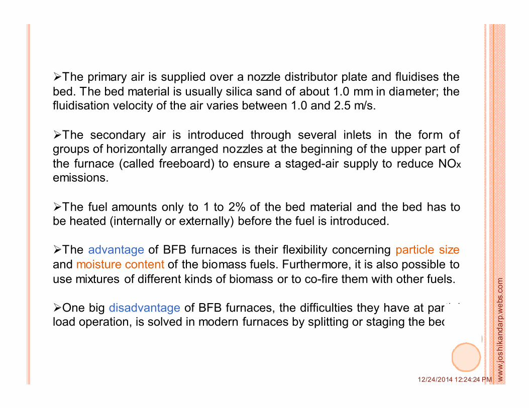
� Higher thermal efficiency (about 40 to 42%) of power station can be
achieved with use of supercritical boiler.

Limitations
� The high pressure and temperature of supercritical boiler have limits for
use due to availability of material and difficulties experienced in the turbine
and condenser operation because of large volumes.
�The additional problem is created due to the separation of solid impurities
as phase changes. These solids remain in the tubes and block the passage
for the flow of feed water. Therefore it is necessary to treat water thoroughly
before supply to the boiler.

When the combustion is carried out under high pressure bysupplying the compressed air then rate of heat transfer is
increased and heating surfaces required is reduced. This theory isused in supercharged boiler.
�The high pressure compressed air is supplied to combustion chamber.Part of heat of hot gases in the furnace is absorbed by boiler tubes in
which water evaporated and then it is superheated in superheater.
�The high pressure and temperature exhaust gases from combustion
chamber are used to run gas turbine. The work produces by gas turbineis used to run air compressor.
�The exhaust gases coming from gas turbine passes over the
economizer tubes. Then escape to the atmosphere through chimney.
In economizer usually pressure of gas side is 5 bar and
pressure to the steam side of 200 bar are preferred.
ww
w.jo
sh
ika
nd
arp
.we
bs.c
om
12/24/2014 12:24:24 PM

Supercharged boiler
ww
w.jo
sh
ika
nd
arp
.we
bs.c
om
12/24/2014 12:24:24 PM

Advantages
� Supercharged boiler requires 30 to 25% of heat transfer surface ofconventional boiler due to very high overall heat transfer co-efficient.
� Due to small heat capacity of the boiler, boiler plant gives better response tocontrol.
� Rapid start of the boiler is possible due to less heating surfaces and
compactness.
� The part of the gas turbine output can be used to drive other auxiliaries.
� Comparatively less number of operators are required.
Limitation:
It requires tight passage for high pressure gas.
Jaitapur Nuclear PP

Fluidized
Bed
Combustion
It is a system in which fluidizedbed which is composed of fuel and inert
material is mixed with air/gas in anatmospheric pressure or pressurized
vessel and combustion take places in
suspended condition of particles in gasstream.
ww
w.jo
sh
ika
nd
arp
.we
bs.c
om
12/24/2014 12:24:24 PM
� When air or other gas flows upward through bed, the bed solid particles aredisturbed. If velocity is increased further, a stage is reached where the composed
(packed) bed becomes turbulent and rapid mixing of particles occurs. Thebehavior of this mixture of solid particles and air or gas is like a fluid. Burning of a
fuel in such a stage is known as fluidized bed combustion.

� The mixture of fuel (crushed coal) and inert material (crushed dolomite* or
limestone) are fed on a distribution plate and air is supplied from the bottom of
distribution plate.
� The air is supplied at high velocity so that solid particles of feed material
remains in suspension condition during burning.
* A kind of sedimentary rock resembling marble or limestone but rich in magnesium carbonate
�The evaporator tubes are directly immersed in
the fluidized bed and direct contact between the
burning coal particles and tubes produce very high
heat transfer rates.

The world power industry is trying to shift from oil / gas to old faithfulfuel coal and this is possible by Fluidized Bed Combustion. There are
two reasons for the rapid increase of fluidized bed combustion (FBC) incombustors.
� First, the liberty of choice in respect of fuels. Not only coal, there is
possibility of using fuels which are difficult to burn using other technologies.This is an important advantage of fluidized bed combustion.
�The second reason, a low emissionof nitric oxides and the possibility of
removing sulfur in a simple manner byusing limestone as bed material.

ww
w.jo
sh
ika
nd
arp
.we
bs.c
om
12/24/2014 12:24:24 PM
FBC systems fit into essentially two major groups, atmospheric systems (FBC)and pressurized systems (PFBC), and two minor subgroups, bubbling (BFB)
and circulating fluidized bed (CFB).
Conventional FBC
Atmospheric fluidized beds use limestone or dolomite to capture sulfur releasedby the combustion of coal. Jets of air suspend the mixture of sorbent and
burning coal during combustion, converting the mixture into a suspension ofred-hot particles that flow like a fluid. These boilers operate at atmospheric
pressure.
PFBC
The first-generation PFBC system also uses a sorbent and jets of air tosuspend the mixture of sorbent and burning coal during combustion. However,
these systems operate at elevated pressures and produce a high-pressure gas
stream at temperatures that can drive a gas turbine. Steam generated from theheat in the fluidized bed is sent to a steam turbine, creating a highly
efficient combined cycle system.

�The pressure inside the bed is atmospheric.�The bed consisting about 97% limestone or inert material and 3%
burning fuel, is suspended by hot primary air entering the bottom of thecombustion chamber.
�There are two types of system based on the fuel feeding arrangement
as underfeed and overfeed.
Conventional FBC
ww
w.jo
sh
ika
nd
arp
.we
bs.c
om
12/24/2014 12:24:24 PM

�In case of underfeed fuel and limestone are introduced from bottom ofthe fluidized bed.
�The overfeed system is simple in operation and economical in running
but results in smaller output per m2 area and gives poor desulphurization
performance.
�Under feed system provides positive load and a compact design butcostly in operation.
Limitation
�The main disadvantage using the conventional FBC is thatincombustible particles (ash and metals) of fuel are came downwards
and block the distributor when light materials like wood dust, agricultural
waste etc. are used as a fuel. There for modifications are required forhigh combustion efficiency.
ww
w.jo
sh
ika
nd
arp
.we
bs.c
om
12/24/2014 12:24:24 PM

Bubbling caps
For plants with a nominal boiler capacity of over 20 MW is suitable.In BFB furnaces, a bed material is located in the bottom part.
Bubbling fluidized bed (BFB)
ww
w.jo
sh
ika
nd
arp
.we
bs.c
om
12/24/2014 12:24:24 PM
�The primary air is supplied over a nozzle distributor plate and fluidises the
bed. The bed material is usually silica sand of about 1.0 mm in diameter; thefluidisation velocity of the air varies between 1.0 and 2.5 m/s.
�The secondary air is introduced through several inlets in the form ofgroups of horizontally arranged nozzles at the beginning of the upper part of
the furnace (called freeboard) to ensure a staged-air supply to reduce NOx
emissions.
�The fuel amounts only to 1 to 2% of the bed material and the bed has tobe heated (internally or externally) before the fuel is introduced.
�The advantage of BFB furnaces is their flexibility concerning particle size
and moisture content of the biomass fuels. Furthermore, it is also possible to
use mixtures of different kinds of biomass or to co-fire them with other fuels.
�One big disadvantage of BFB furnaces, the difficulties they have at partialload operation, is solved in modern furnaces by splitting or staging the bed.
ww
w.jo
sh
ika
nd
arp
.we
bs.c
om
12/24/2014 12:24:24 PM

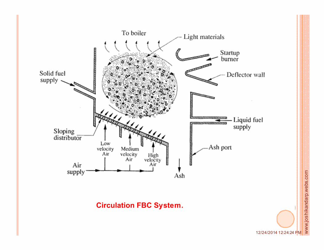
Circulation FBC System.
ww
w.jo
sh
ika
nd
arp
.we
bs.c
om
12/24/2014 12:24:24 PM

�To increases the efficiency of combustion - provide non uniform fluidizing velocities over the bed,
- provide slope to one of the FBC walls- provide sloping distributor plate to give an air slide particles.
�Due to above there is significant improvement and allowed to use light materials as fuels most successfully.
� Light materials were burned within the bed and heavy incombustibles
(ash and metals) gathered at the bottom of the sloping distributor.
�The solid fuel enters the furnace from the side of walls. The low velocity (LV), medium velocity (MV) and high velocity (HV) air supplied at different
points along the sloping surface of the distributor plate. The secondary air
is supplied over the bed. The ash port is provided at lower end of the distributor plate.
ww
w.jo
sh
ika
nd
arp
.we
bs.c
om
12/24/2014 12:24:24 PM

ww
w.jo
sh
ika
nd
arp
.we
bs.c
om
12/24/2014 12:24:24 PM

ww
w.jo
sh
ika
nd
arp
.we
bs.c
om
12/24/2014 12:24:24 PM

�In this system pressurized air (10 bar approximately) is used forfluidization and combustion.
�Boiler exit gas contain enough energy about temperature 850 to 900°C
to drive a gas turbine. The power output of gas turbine is utilized to run
the air compressor and the electric generator.
�Here, the product of combustion have to be sufficient clean for gasturbine to prevent excessive erosion, corrosion or fouling of the turbine.
Hence, the flue gases from the combustion chamber are passed through
a cyclone separator.
Advantages:In PFBC system, high rate of coal loading and burning is achieved.
Comparatively less volume of furnace is required, hence plant size is
reduced. It has improved desulphurization and low NOx emission.
Disadvantages :(1) The controlling is difficult to control. With compare to conventional
plant, life is low.
ww
w.jo
sh
ika
nd
arp
.we
bs.c
om
12/24/2014 12:24:24 PM

SUPERHEATERS
The function of the superheater in the thermal power plant is to remove the
last traces of moisture ( 1 to 2%) from the saturated steam coming out of
boiler and to increase its temperature sufficiently above saturation
temperature.
The super-heating raises overall cycle efficiency as well as avoids too much
condensation in the last stages of the turbine which avoids the blade
erosion.
The heat of combustion gases from furnace is utilized for the removal of
moisture from steam and to superheat the steam. Super-heaters usually
have several tube circuits in parallel with one or more return bends,
connected between headers.
ww
w.jo
sh
ika
nd
arp
.we
bs.c
om
12/24/2014 12:24:24 PM

Su
pe
rhe
ate
r T
em
p
% of load capacity
The steam issuperheated by transferring
the heat of gases either byconvection or by radiation or
by combined convection and
radiation.
The combined typesuperheater has proved most
desirable as it keeps the
constant temperaturethroughout the load range.
ww
w.jo
sh
ika
nd
arp
.we
bs.c
om
12/24/2014 12:24:24 PM

ww
w.jo
sh
ika
nd
arp
.we
bs.c
om
12/24/2014 12:24:24 PM

The principle of convection superheater is similar to steam generating tubes
of the boiler. The hot gases at high temperature sweep over superheatertubes and raise the temperature of steam which magnitude depends upon
exit gas temperature leaving the superheater and gas-velocity.
The convection superheater may be set as "Interdeck Form" or
"Overdeck Form" .
The superheater is placedbetween the water tubes in
interdeck arrangement
it is located above the water
tubes in case of overdecktype.
Interdeck superheater
ww
w.jo
sh
ika
nd
arp
.we
bs.c
om
12/24/2014 12:24:24 PM

overdeck superheater
Inerbank superheater
Inertube superheater
A radiant superheater is located in the furnace
wall and absorbs heat from the luminous fuelsource just as the furnace wall tubes transmit
radiant heat the saturated water in the wall
tubes.
ww
w.jo
sh
ika
nd
arp
.we
bs.c
om
12/24/2014 12:24:24 PM

The common methods used for controlling the superheat temperature of thesteam are discussed below :
1. Bypassing the furnace gas around the superheater. At lower loads on the
power plant, the part of the gases are bypassed with the help of damper as
shown in Fig. (a). Until recently, this method of control was used successfully.But the troubles with satisfactory materials to withstand erosion and high
temperatures in the gas passages have limited the use of damper method ofcontrol.
2. Tilting burners in the furnace. The temp.of the steam coming out of superheater is
controlled by titling burners up or downthrough a range of 30°C as shown in Fig (b).
By tilling the burner downward in afurnace much of the heat is given to the water
walls by the gas and the gas entering thesuperheater region is relatively cool.
If the burner is turned upward, then
the heat given to the boiler water wall is lessand hotter gas enters the superheater region
to increase the steam temperature.

3. Auxiliary burners. The temperature of the steam can be controlled byturning the auxiliary burners in addition to main burners. The effect of this is
similar to tilting burners. The arrangement is shown in Fig. (c).
4. Desuperheater usingwater spray. The
temperature of the steamcan be controlled by
injecting the water either
before the superheater orbetween sections of a
superheater as shown inFig. (d).

5. Pre-condensing control. The temperature of the steam can he controlled bycondensing the steam coming out of boiler with a small condenser with the help of
feed water as shown in Fig. (e). Automatic control regulates the amount of feedwater by-passed.
6. Gas recirculation. The gas coming out of economiser is partly recirculated intothe furnace with the help of a fan as shown in Fig. (F). The recirculated gas acts
like excess air and blankets the furnace wall. This reduces the heat absorption bywater wall and increases the heat absorption by superheater.
ww
w.jo
sh
ika
nd
arp
.we
bs.c
om
12/24/2014 12:24:24 PM

7. Twin furnace arrangement.
The twin furnace arrangementas shown in Fig. (g) is an
extension of the separately fired
superheater. Varying the firingrates between furnaces controls
the superheat temperature.
ww
w.jo
sh
ika
nd
arp
.we
bs.c
om
12/24/2014 12:24:24 PM

ww
w.jo
sh
ika
nd
arp
.we
bs.c
om
12/24/2014 12:24:24 PM
REHEATERS
Function: The function of the re-heaters is to resuperheat the partly
expanded steam from the turbine. This is done so that the steam
remains dry as far as possible through the last stage of the turbine.
Location: Before or after the convective superheater in the convective zone
of utility boilers.
In modern high pressure boilers, reheaters are generally in two
sections. The primary section is placed in the convective zone and secondarysection is placed just at the furnace exit hanging from the top.
The design consideration for reheaters are similar to those forsuperheaters. It having same output temperatures but steam pressures are
about 20-25% of those in superheaters. Hence lower grade steel alloy can beused for reheaters.

ECONOMIZER
The first successful design of economizer was used to increase the steam-
raising efficiency of the boilers of stationary steam engines. It was patented
by Edward Green in 1845, and since then has been known as Green's economizer.
Function:When the combustion gases leave the boiler after giving most of their heat
to evaporator tubes, superheated tubes and reheater tubes, they still posses lot
of heat, such heat used by this device to increases the temperature of feed water.
Economizers are so named because they can make use of the enthalpy influid streams that are hot, but not hot enough to be used in a boiler, thereby
recovering more useful enthalpy and improving the boiler's efficiency
Economizers are commonly used as part of a heat recovery steam generator in a combined
cycle power plant.

ww
w.jo
sh
ika
nd
arp
.we
bs.c
om
12/24/2014 12:24:24 PM

Classification of economizers:
1. Based on construction
(i) Plain tube type economizers: The external surface of tubes is kept clean and free from soot by soot scrapers moving up and down the economizer
tubes. Otherwise heat transfer resistance is increase and efficiency of economizer decreased.
ww
w.jo
sh
ika
nd
arp
.we
bs.c
om
12/24/2014 12:24:24 PM

(ii) Gilled tube type economizers:
Rectangular gills are provided on the bare tube walls to increases the heat transfer surfaces .
ww
w.jo
sh
ika
nd
arp
.we
bs.c
om
12/24/2014 12:24:24 PM

2. Based on part of steam generation
(i) Steaming type economizers: some part of the water (about 5 to 7%) tobe converted into steam during its passage through the economizer.
(ii) Non-steaming type economizers: While in case of non steamingeconomizer feed water is heated within 75% of the saturation
temperature of the boiler.
3. Based on location of economizers(i) Independent economizers: economizer is installed
outside the boiler house at any convenient place
(i) Integral economizers: economizer is installed close
to the boiler.

ww
w.jo
sh
ika
nd
arp
.we
bs.c
om
12/24/2014 12:24:24 PM
Advantages of economizers:
(1) It improves the boiler efficiency. It has been found that about 1%
efficiency of boiler is increased by increasing temperature of feed waterby 6 °C with help of economiser.
(2) It reduces the losses of heat with the flue gases, The temperature of flue
gases is about 370°C to 540°C at exit of last superheater or reheater,
having large amount of heat energy which otherwise would have beenwasted.
(3) It reduces the consumption of fuel. It has been estimated that about 1% of
fuel costs can be saved for every 6 °C rise in temperature of the boiler
feed water.
(4) It reduces thermal stresses in the boiler due to reduced temperaturedifferential in the boiler.

AIR PRE-HEATERS
Function : The air preheaters are employed to recover the heat from theflue gases and this heat is utillized to increased the temperature of air
before it supply to the furnace.
Location: An air preheater is placed between the economizer and the
chimney and it extracts heat from the flue gases and transfers to air which isentering the furnace. The portion of the heat that otherwise would pass up the
chimney to waste.
Advantage of pre-heating the air :
(1) It increases the temperature of the furnace gases, improves combustionrates and combustion efficiency.
(2) Air preheater extracts heat from the flue gases, and lowers stacktemperatures thus improving the overall efficiency of the boiler. It has found
that a drop of 20-22°C in the flue gases temperature increases boiler
efficiency by 1%.(3) The preheating air facilitates the burning of poor grades of fuel thus
permitting a reduction in excess air.(4) It increases steam generating capacity per unit m2 of boiler surface.
(5) Increased thermal efficiency of plant and saving of fuel.
ww
w.jo
sh
ika
nd
arp
.we
bs.c
om
12/24/2014 12:24:24 PM

Types of air preheaters :
(1) Recuperative type :(i) Plate type (ii) Tubular type
(2) Regenerative type
(1) Recuperative type air preheaters
In recuperative type of air preheaters, the two fluids(air and flue gases) are separated by heat transfer surface.
Recuperative type of air preheater is further classified as
tubular type and plate type.
ww
w.jo
sh
ika
nd
arp
.we
bs.c
om
12/24/2014 12:24:24 PM

The horizontal bafflesare provided to increase time of
contact which will help for higherheat transfer.
A soot hopper is fitted
to the bottom of air heater casingto collect soot.
Tubular air preheater:
It consists of a large number of tubes rolled into sheets asshown in Fig. The flue gases flow through tubes and air is passed over
the outer surface of the tubes in a direction opposite to that of flue gases
flow.

Plate type air preheater:
It consists of rectangular flat plates spaced from 1.25 cm to 2.5 cmapart formed alternate flue gases and air passages as shown in Fig.
This type of air preheater is more expensive for installation and
maintenance compared to tubular type, hence it is not used in modern powerplants.
ww
w.jo
sh
ika
nd
arp
.we
bs.c
om
12/24/2014 12:24:24 PM

Regenerative type air preheater has a energy storage medium called thematrix which is alternately exposed to the hot and cold fluids.
The rotor divided into a number of sectors (12 to 24 sectors), each sector
being fixed with steel sheets.
The rotor is placed in a drum which has been divided into two compartments,
air and flue gases compartments. To avoid leakage from one compartment tothe other seals are provided.
The rotor rotates at a veryslow speed of 3-4 rpm.

ww
w.jo
sh
ika
nd
arp
.we
bs.c
om
12/24/2014 12:24:24 PM

Corrosion is the destructive conversion of metal into oxides or salts.
Corrosion may occur in the boiler shell, evaporating tubes superheater,
economises and air preheaters.
The presence of O2 is mostly responsible for corrosion among other
factors. Oxygen generally enters a closed system through make up condenserleakage and condensate pump packings.
The CO2 is next to O2 which is responsible for corrosion, it comes outof bicarbonates on heating and it combines with water to form weak acid known
as carbonic acid.
Hydrogen embrittlement of mild steel boiler tubing occurs in high-
pressure boilers when atomic hydrogen forms at the boiler tube surface as aresult of corrosion.
On the external surface of boiler accessory, corrosion generally depends on
-ash properties, - rate of ash deposition,
-tube surface temperature and - chromium percentage in the tube material.
CORROSION
ww
w.jo
sh
ika
nd
arp
.we
bs.c
om
12/24/2014 12:24:24 PM

ww
w.jo
sh
ika
nd
arp
.we
bs.c
om
12/24/2014 12:24:24 PM
Galvanic CorrosionThe most common type of galvanic corrosion in a boiler system is caused by the
contact of dissimilar metals, such as iron and copper. These differential cellscan also be formed when deposits are present. Galvanic corrosion can occur at
welds due to stresses in heat-affected zones or the use of different alloys in the
welds.
Caustic CorrosionConcentration of caustic (NaOH) can occur either as a result of steam
blanketing or by localized boiling beneath porous deposits on tube surfaces.
[Steam blanketing is a condition that occurs when a steam layer forms betweenthe boiler water and the tube wall. Under this condition, insufficient water
reaches the tube surface for efficient heat transfer. The water that does reach theoverheated boiler wall is rapidly vaporized, leaving behind a concentrated caustic
solution, which is corrosive.]
Acidic Corrosion
Low makeup or feedwater pH can cause serious acid attack on metal surfaces inthe preboiler and boiler system. Even if the original makeup or feedwater pH is
nnormal, feedwater can become acidic from contamination of the system.

ww
w.jo
sh
ika
nd
arp
.we
bs.c
om
12/24/2014 12:24:24 PM
(1)Corrosion at inner surfaces (water/steam side): the corrosion is
caused by
- an acid or low pH value in water and
- the presence of O2 , CO2 or chlorides dissolved in feed water.
Methods of inner surface corrosion preventions :
(1)A proper designed deaerator combined with water treatment plant is
used to remove the dissolved O2, and CO2.
(2)Dissolved oxygen can be removed by balanced amount of
scavengers like hydrazine sodium sulphate
(3) The effect of C02 is neutralized by the addition of ammonia for
neutralizing amines in water.
(4)The corrosion of metal surfaces can be prevented by applying
protective coating of amines to the internal surfaces of boilers
tubes.

(2) Corrosion at external surface:
The external corrosion is mainly caused by coal ash when the temperaturerange is between 540°C to 710°C. Alkali sulphates deposits on tube
surfaces and corrosion starts.
High temperature of superheater and reheaters favour the formation of low-melting compounds like sodium or potassium iron. These corrosion is
known as high temperature corrosion.
Low temperature corrosion may take place at economizer and air pre
heater. External corrosion of the economizer tubes is very serious when highsulphur content wet fuels are used in the boiler furnace .
External corrosion also occurs if flue gases contains water vapour, which
condenses at the tube surfaces. Sulphurous acid is formed when S02 is
dissolved in free moisture in the flue gases.
ww
w.jo
sh
ika
nd
arp
.we
bs.c
om
12/24/2014 12:24:24 PM

Methods of external surface corrosion preventions :
(1)High temp corrosion may be reduce by using good quality of
coal and selection of high grade metal alloys.
(2)Low temp corrosion can be prevented in economizer by pre
heating the feed water by steam.
(3)To avoid corrosion of air pre heater temperature of flue
gases should not be fall down below the dew point
temperature.
ww
w.jo
sh
ika
nd
arp
.we
bs.c
om
12/24/2014 12:24:24 PM

MECHANICAL CONDITIONS AFFECTING CORROSION
Many corrosion problems are the result of mechanical and operationalproblems. The following practices help to minimize these corrosion
problems:
�Selection of corrosion-resistant metals
�Reduction of mechanical stress where possible (e.g., use of proper
welding procedures and stress-relieving welds)
�Minimization of thermal and mechanical stresses during operation within
design load specifications, without over-firing, along with proper start-upand shutdown procedures
�Maintenance & Cleaning of systems, including the use of high-purity
feedwater, effective and closely controlled chemical treatment, and acid
cleaning when required
ww
w.jo
sh
ika
nd
arp
.we
bs.c
om
12/24/2014 12:24:24 PM

DEAERATOR
ww
w.jo
sh
ika
nd
arp
.we
bs.c
om
12/24/2014 12:24:24 PM
� A deaerator is a device that is widely used for the removal of air and
other dissolved gases from the feed water to steam-generating boilers. In
particular, dissolved oxygen in boiler feed waters will cause serious
corrosion damage in steam systems by attaching to the walls of metal
piping and other metallic equipment and forming oxides (rust). Water
also combines with any dissolved carbon dioxide to form carbonic acid
that causes further corrosion. Most deaerators are designed to remove
oxygen down to levels of 7 ppb by weight (0.0005 cm³/L) or less.
� There are two basic types of deaerators, the tray-type and the spray-type:
� The tray-type (also called the cascade-type) includes a vertical domed
deaeration section mounted on top of a horizontal cylindrical vessel
which serves as the deaerated boiler feedwater storage tank.
� The spray-type consists only of a horizontal (or vertical) cylindrical vessel
which serves as both the deaeration section and the boiler feedwater
storage tank.

A schematic diagram of a typical tray-type deaerator.
ww
w.jo
sh
ika
nd
arp
.we
bs.c
om
12/24/2014 12:24:24 PM

A schematic diagram of a typical spray-type deaerator.
ww
w.jo
sh
ika
nd
arp
.we
bs.c
om
12/24/2014 12:24:24 PM