Embed Size (px)
Citation preview

High Pressure Forged Gate ValvesFig. 6012 – 6015
Tyco reserves the right to change the contents without notice RAILT-0005-EN-0403
Raimondi valves offer a new, technologicallyadvanced concept for high pressure and hightemperature applications.
Features• Design fully in accordance with a large
range of standards such as ASMEB16.34, API 600, ISO, DIN, TRD, VGB,TRB, PED.
• Raimondi valve range is manufacturedonly in high quality forged materials tomaximize their reliability andperformance.
• Pure graphite packing and gasket designguarantees extreme tightness andfollows the Health, Safety andEnvironment requirements to minimizeany risk of fugitive emissions.
• The robust, advanced pressure sealbonnet design is easily accessible forany maintenance operation.
• Flexible split wedge is offered asstandard on Raimondi gate valves. Thewedge guide is integral to the body, thusavoiding any welding. Parallel slides arealso available.
• Bolted Bonnet available.• Special constructions and materials
available.• CE mark 100% Compliance with
European Pressure Equipment Directiven°97/23/EC
Technical dataPressure ratings : ASME: from 900# to
4500#DIN: from PN 160 to PN720
Body materials : forged carbon steels,alloys steels and stainlesssteels. All in compliancewith ASME and DINstandards
Temperature (°C) : -46 to + 650Sizes (mm) : 50 – 750 (2”-30”)
Connections standardsFlanges : ASME B16.5.Buttweld : ASME B16.25, DIN 2448Other connections on request.
General applicationRaimondi forged steel valves have beendesigned for high pressure and hightemperature applications in power plants.Furthermore, Raimondi valves are highlyrecommended for installation in chemicaland petrochemical plants, and offshoreplants.
www.tycovalves-eu.com

High Pressure Forged Gate ValvesPressure temperature ratings to ASME
Tyco reserves the right to change the contents without notice page 2
Test pressure to API 598 and ASME B16.34 (bar)
Hydrostatic shell test Hydrostatic seat test Pneumatic test
233 171 >5,6
A105 / LF2 F11, F12 F22 F91 F316 A105 / LF2 F11, F12 F22 F91 F316
(LCB) (WC6) (WC9) (CF8M) (LCB) (WC6) (WC9) (CF8M)
C22.8 13CrMo44 10CrMo910 X10CrMoVNb91 X6CrNiNb1810 C22.8 13CrMo44 10CrMo910 X10CrMoVNb91 X6CrNiNb1810
1.046 1.7335 1.738 1.4903 1.455 1.046 1.7335 1.738 1.4903 1.455
STANDARD CLASS SPECIAL CLASS
Temp. Working pressure (bar)
°C ASME 900
-29 - 38 153,2 155,1 155,1 155,03 148,9 155,2 155,2 155,2 155,03 155,150 150,2 153,4 153,6 155,03 144,4 155,2 155,2 155,2 155,03 152,1100 139,1 146,3 147,1 155,03 126,6 155,2 155,2 155,2 155,03 139,2150 135,7 139,1 139,9 150,55 115,5 155,2 155,2 155,2 155,03 125,8200 131,5 136,4 134,5 145,72 107 155,2 155,2 155,2 155,03 118,8250 125,2 133,4 132,7 137,46 100,2 155,2 155,2 153 155,03 111,4300 116,2 127,3 127,3 125,05 94,9 149,6 155,2 152,5 155,03 105,8350 110,9 120,7 120,7 121,61 91,3 144,4 147,5 152,3 151,58 101,5400 103,5 109,8 109,8 109,9 87,3 129,4 137,2 150,7 150,55 97,5425 86,3 105,3 105,3 105,07 86 107,8 131,6 149,1 148,82 96450 60,1 101,4 101,4 100,59 84,2 75,1 126,8 141,5 139,87 94500 26,4 83,4 83,4 93,02 80,5 33 104,2 107,1 124,02 89,8525 15,5 60,8 65,8 79,92 78,9 19,4 76 82,2 97,49 88,8550 38,3 49,1 75,1 74,9 47,9 61,4 86,81 88,8600 17,6 22,9 62,35 64,3 22,1 28,6 77,86 80,4650 29,63 42,4 37,21 53
Test pressure to API 598 and ASME B16.34 (bar)
Hydrostatic shell test Hydrostatic seat test Pneumatic test
388 285 >5,6
ASME 1500
-29 - 38 255,3 258,6 258,6 258,37 248,1 258,6 258,6 258,6 258,37 258,550 250,4 255,7 256 258,37 240,6 258,6 258,6 258,6 258,37 251,8100 231,9 243,8 245,2 250,80 211 258,6 258,6 258,6 258,37 224,6150 226,1 231,9 233,2 243,22 192,5 258,6 258,6 258,6 258,37 202200 219,1 227,4 224,2 229,09 178,4 258,6 258,6 258,6 258,37 182,1250 208,6 222,3 221,1 208,42 166,9 258,6 258,6 255 258,37 170,3300 193,7 212,1 212,1 202,57 158,1 249,3 258,6 254,2 258,37 162350 184,8 201,2 201,2 195,68 152,1 240,6 245,8 253,8 252,52 156,3400 172,5 182,9 182,9 183,27 145,6 215,6 228,7 251,1 251,14 153,2425 143,8 175,5 175,5 175,01 143,3 179,7 219,3 248,3 248,04 150,9450 100,2 169 169 167,77 140,4 125,2 211,3 235,9 233,23 149,5500 44 139 139 154,68 134,1 55 173,7 178,5 206,7 144,9525 25,9 101,3 109,6 132,98 131,5 32,4 126,7 137 162,60 141550 63,8 81,8 125,40 124,8 79,8 102,3 145,03 136,3600 29,4 38,2 104,04 107,2 36,8 47,7 129,88 104,5650 49,61 70,6 62,01 65,7
Test pressure to API 598 and ASME B16.34 (bar)
Hydrostatic shell test Hydrostatic seat test Pneumatic test
646 474 >5,6
ASME 2500
-29 - 38 425,5 431 431 430,62 413,6 431 431 431 430,62 430,950 417,3 426,2 426,7 430,62 401 431 431 431 430,62 422,4100 386,5 406,4 408,7 418,22 351,7 431 431 431 430,62 386,6150 376,9 386,4 388,6 405,13 320,9 431 431 431 430,62 349,4200 365,2 379 373,7 381,71 297,3 431 431 431 430,62 330,1250 347,7 370,6 368,5 347,26 278,2 431 431 425 430,62 309,4300 322,8 353,5 353,5 337,95 263,6 415,5 431 423,6 430,62 293,9350 308 335,3 335,3 325,90 253,8 401,1 409,7 423,1 420,98 282,1400 287,5 304,9 304,9 305,23 242,6 359,4 381,5 418,5 418,22 270,8425 239,6 292,5 292,5 291,45 238,9 299,6 365,6 414,1 413,4 266,6450 166,9 281,7 281,7 279,73 234 208,7 352,1 393,1 388,94 261,2500 73,3 231,6 231,6 258,03 223,6 91,6 289,6 297,5 344,5 249,5525 43,2 168,9 182,7 221,86 219,1 53,9 211,1 228,4 270,78 224,5550 106,4 136,4 208,77 208 133 170,4 241,49 224,5600 49 63,6 173,28 178,6 61,3 79,5 216,69 223,3650 82,68 117,1 103,35 197,1

Tyco reserves the right to change the contents without notice page 3
High Pressure Forged Gate ValvesPressure temperature for ISO materials
Pressure rating
TT 5 1.0460 15Mo3 13CrMo44 15NiCuMoNb5 10CrMo910 X10CrMoVNb91 X6CrNiNb1810
(GS-C25) (GS 22Mo4) (GS 17CrMo55) (GS18CrMo910)
1.0411 1.5415 1.7335 1.6368 1.7380 1.4903 1.455
LF2 A105 F1 F11, F12 F22 F91 F316
(LCB) (WCB) (WC6) (WC9) (CF8M)
Temp. Working pressure (bar)
°C Pressure rating 09 (PN 160)
-50 200 166-29 - 38 200 200 220 320 16650 192 192 220 320 157100 185 185 220 320 148150 168 168 195 320 137200 150 150 175 320 130250 130 130 165 185 320 125300 115 115 140 172 320 115350 95 95 135 165 320 110400 81 81 130 155 320 105425 64 64 128 150 275 102450 58 58 125 145 230 155 200 100500 82 130 135 183 95520 47 88 102 153 93540 35 55 77 136 92550 45 65 120 90575 40 90 85600 68 80625 50 65650 35 60
Pressure rating 15 (PN 250)
-50 290 275-29 - 38 290 290 335 420 27550 280 280 335 420 255100 275 275 320 420 240150 260 260 300 420 230200 236 236 275 420 220250 205 205 255 295 420 200300 180 180 220 275 420 190350 152 152 210 255 420 180400 124 124 205 240 420 175425 107 107 200 232 372 170450 94 94 195 225 311 240 356 165500 130 202 210 300 160520 77 132 160 252 150540 88 120 211 146550 65 103 193 142575 68 153 125600 105 110625 78 80650 54 70
Pressure rating 25 (PN 500)
-50 455 455-29 - 38 455 455 520 695 45550 455 455 520 695 440100 455 455 520 695 400150 405 405 482 695 360200 380 380 465 695 340250 345 345 425 440 695 320300 285 285 372 408 695 310350 227 227 355 384 695 300400 190 190 315 360 695 290425 165 165 310 350 615 275450 142 142 298 335 510 360 520 270500 258 315 450 260520 185 230 385 250540 130 185 320 235550 100 146 285 230575 100 215600 150 220625 108 170650 65 150

Tyco reserves the right to change the contents without notice page 4
High Pressure Forged Gate ValvesMaterials to ASTM and ISO
Materials to ASME
Chemical Requirements Mechanical Properties
ASTM Composition % R S min A min C min
Standard C Mn P S Si Cr Mo Ni Mpa Mpa % %
Forged Body
A 105N 0,25 0,6-1,05 max 0,04 max 0,04 max 0,35 - - - 485 min 240 22 30A 182 F1 max 0,25 0,6-0,9 max 0,045 max 0,045 max 0,35 - - 0,44-0,65 485 min 270 20 30A 182 F11 (F12) 0,1-0,2 0,3-0,8 max 0,04 max 0,04 0,15-0,6 0,8-1,25 0,44-0,65 - 485 min 300 20 30A 182 F22 0,05-0,15 0,3-0,6 max 0,04 max 0,04 max 0,5 2,0-2,5 0,87-1,13 - 515 min 300 20 30A 182 F5 max 0,15 0,3-0,6 max 0,03 max 0,03 max 0,5 4,0-6,0 0,44-0,65 max 0,5 485 min 275 20 35A 182 F9 max 0,15 0,3-0,6 max 0,03 max 0,03 0,5-1,0 8,0-10,0 0,9-1,1 - 585 min 380 20 40A 182 F91 0,08-0,12 0,3-0,6 max 0,02 max 0,01 0,2-0,5 8,0-9,5 0,85-1,05 max 0,4 585 min 415 20 40A 182 F304 max 0,08 max 2,0 max 0,04 max 0,03 max 1,0 18,0-20,0 - 8,0-11,0 515 min 205 30 50A 182 F316 max 0,08 max 2,0 max 0,04 max 0,03 max 1,0 16,0-18,0 2,0-3,0 10,0-14,0 515 min 205 30 50A 182 F321 max 0,08 max 2,0 max 0,03 max 0,03 max 1,0 min 17,0 Ti 0,1-0,18 9,0-12,0 515 min 205 30 50A 350 LF2 0,35 max 1,35 max 0,035 max 0,04 0,15-0,3 max 0,3 max 0,12 max 0,9 485 min 240 22 30
Stem
A 182 F6 cl.2 max 0,15 max 1,0 max 0,04 max 0,03 max 1,0 11,5-13,5 - max 0,5 585 min 380 18 35A 182 F304 max 0,08 max 2,0 max 0,04 max 0,03 max 1,0 18,0-20,0 - 8,0-11,0 515 min 205 30 50A 182 F316 max 0,08 max 2,0 max 0,04 max 0,03 max 1,0 16,0-18,0 2,0-3,0 10,0-14,0 515 min 205 30 50A 182 F321 max 0,08 max 2,0 max 0,03 max 0,03 max 1,0 min 17,0 Ti 0,1-0,18 9,0-12,0 515 min 205 30 50A 638 Gr.660 max 0,08 max 2,0 max 0,04 max 0,03 max 1,0 13,5-16,0 1,0-1,5 24,0-27,0 895 min 585 15 18A 564 Type 630 17.4 PH max 0,07 max 1,6 max 0,04 max 0,03 max 1,0 15,0-17,5 Co 3,0-5,0 3,0-5,0 930 min 725 16 50
Cast Body
A 216 WCB max 0,3 max 1,0 max 0,04 max 0,045 max 0,6 - - - 485-655 250 22 35A 352 LCB max 0,3 max 1,0 max 0,04 max 0,045 max 0,6 - - - 450-620 240 24 35A 217 WC6 max 0,2 0,5-0,8 max 0,04 max 0,045 max 0,6 1,0-1,5 0,45-0,65 - 485-655 275 20 35A 217 WC9 max 0,18 0,4-0,7 max 0,04 max 0,045 max 0,6 2,0-2,75 0,9-1,2 - 485-655 275 20 35A 217 C5 max 0,2 0,4-0,7 max 0,04 max 0,045 max 0,75 4,0-6,5 0,45-0,65 - 620-795 415 18 35A 217 C12 max 0,2 0,35-0,65 max 0,04 max 0,045 max 1,0 8,0-10,0 0,9-1,2 - 620-795 415 18 35A 217 CA15 max 0,15 max 1,0 max 0,04 max 0,04 max 1,5 11,5-14,0 max 0,5 max 1,0 620-795 450 18 30A 351 CF3M max 0,03 max 1,5 max 0,04 max 0,04 max 1,5 17,0-21,0 2,0-3,0 9,0-13,0 485 min 205 30 -A 351 CF8M max 0,08 max 1,5 max 0,04 max 0,04 max 1,5 18,0-21,0 2,0-3,0 9,0-12,0 485 min 205 30 -
Bolts and Nuts
A 193 B7 0,37-0,49 0,65-1,1 max 0,035 max 0,04 0,15--0,35 0,75-1,2 0,15-0,25 - 720A 193 B16 0,36-0,47 0,45-0,7 max 0,035 max 0,04 0,15--0,35 0,8-1,15 0,5-0,65 V 0,25-0,35 860 725A 193 B8 max 0,08 max 2,0 max 0,045 max 0,03 max 1,0 18,0-20,0 - 8,0-10,5 205A 320 L7 0,38-0,48 0,75-1,0 max 0,035 max 0,04 0,15--0,35 0,8-1,1 0,15-0,25 -A 307 B - - max 0,04 max 0,05 - - - -A 194 2H min 0,4 max 1,0 max 0,04 max 0,05 max 0,4 - - -A 194 4 0,4-0,5 0,7-0,9 max 0,035 max 0,04 0,15-0,35 - 0,2-0,3 -A 194 8 max 0,08 max 2,0 max 0,045 max 0,03 max 1,0 18,0-20,0 - 8,0-10,5
Materials to ISO
Chemical Requirements Mechanical Properties
Composition % S A C
DIN R min min min
No. Type C Mn P S Si Cr Mo Nb Ni Mpa Mpa % %
Forged Body
1.0460 C22.8 max 0,25 0,3-0,6 0,045 0,045 0,15-0,35 - - - - 485-520 240 22 301.5415 15Mo3 0,12-0,2 0,5-0,7 0,04 0,04 0,15-0,35 - 0,25-0,35 - - 485-530 270 22 301.7335 13CrMo44 0,1-0,18 0,4-0,7 0,04 0,04 0,15-0,35 0,7-1,0 0,4-0,5 - - min 490 300 20 301.7380 10CrMo910 max 0,15 max 0,5 0,04 0,04 max 0,5 2,3 1,0 - - Cu min 520 300 20 351.6368 15NiCuMoNb5 max 0,17 0,8-1,2 0,035 0,035 max 0,5 max 0,3 max 0,4 max 0,8 1,0-1,3 max0,8 620-760 430 16 -1.4903 X10CrMoVNb91 max 0,15 0,3-0,6 0,03 0,03 0,5-1,0 8,0-10,0 0,9-1,1 max 0,5 - Ti 750-900 560 20 301.4541 X10CrNiTi189 max 0,1 max 2,0 0,045 0,03 max 1,0 - - - 9,0-11,5 >5xC min 485 295 30 501.4550 X10CrNiMo189 max 0,1 max 2,0 0,045 0,03 max 1,0 17,0-19,0 1,9-1,0 - 9,0-11,5 >5xC min 485 295 30 501.4571 X10CrNiMoTi18.10 max 0,1 max 2,0 0,045 0,03 max 1,0 16,5-18,5 2,0-2,5 - 10,5-13,5 >5xC min 485 205 30 501.0411 TT5 0,22-029 0,9-0,7 0,045 0,045 max 0,4 - - - - - 485-520 240 22 30
Stem
1.4021 X20Cr13 0,17-0,22 max 1,0 0,045 0,03 max 1,0 12,0-14,0 - - - - 600-900 450 12 -1.4122 X35CrMo17 0,33-0,45 max 1,0 0,045 0,03 max 1,0 16,5 - - 8,0-10,0 - 760-900 600 14 -1.4057 X22CrNi17 0,17-0,25 max 1,0 0,045 0,03 max 1,0 16,0-18,0 1,15 - max 1,0 - 760-900 600 9 -1.4980 X5NiCrTi26,15 max 0,08 max 2,0 0,045 0,03 max 1,0 13,5-16,0 max 1,5 max 0,5 24,0-27,0 max2,3 900-1100 650 30 50
Cast Body
1.0614 GS-C25 0,18-0,23 0,5-0,8 0,05 0,05 0,3-0,5 max 0,3 - - - - 450-600 290 22 351.5419 GS-22Mo4 0,18-0,23 0,5-0,8 0,04 0,04 0,3-0,5 max 0,3 - - - - 450-600 270 24 351.7357 GS-17CrMo55 0,15-0,2 0,6-0,8 0,04 0,04 0,3-0,5 1,0-1,5 - - - - 485-655 275 24 351.7379 GS-18CrMo910 0,12 0,6 0,04 0,04 0,4 2,25 - - - - 485-655 275 20 351.4562 GX7CrNiMo189 max 0,08 max 1,5 0,045 0,03 max 1,5 17,5-20,0 - - 9,0-10,0 - min 485 205 30 -
Bolts and Nuts
1.1181 CK35 0,32-0,4 0,4-0,7 0,035 0,035 0,15-0,35 max 0,5 - - - - 500-600 280 22 -1.7258 29CrMo55 0,20-0,29 0,5-0,8 0,035 0,035 0,15-0,35 0,9-1,2 0,2-0,3 - max 0,6 - 600-750 450 18 -1.7709 24CrMoV55 0,20-0,29 0,3-0,6 0,035 0,035 0,15-0,35 1,2-1,5 0,5-0,6 - max 0,6 - 700-950 550 17 -1.4301 X5CrNi189 max 0,07 max 2,0 0,045 0,03 max 1,0 17,0-20,0 - - 9,0-11,5 - 500-700 320 45 -1.4921 X19CrMo121 0,19 max 0,8 0,045 0,03 max 0,5 11-12,5 max 1,3 - - - 750-900 550 14 -1.4923 X22CrMoV121 0,22 max 0,7 0,045 0,03 max 0,4 10,5-12,5 max 1,2 - max 0,8 - 850-950 600 14 -

Butt Welding Ends for Forged Steel Valves to ASME B16.25
t
ND ND A
sch.std sch.XS sch.40 sch.60 sch.80 sch.100 sch.120 sch.140 sch.160 sch.XXS
50 2" 60,3 3,91 5,54 3,91 5,54 8,74 11,0765 2 1/2" 73 5,16 7,01 5,16 7,01 9,53 14,0280 3"" 88,9 5,49 7,62 5,49 7,62 11,13 15,24100 4" 114,3 6,02 8,56 6,02 8,56 11,13 13,49 17,12125 5" 141,3 6,55 9,53 6,55 9,53 12,7 15,88 19,05150 6" 168,3 7,11 10,97 7,11 10,97 14,27 18,26 21,95200 8" 219,1 8,18 12,7 8,18 10,31 12,7 15,09 18,26 20,62 23,01 22,23250 10" 273,1 9,27 12,7 9,27 12,7 15,09 18,26 21,44 25,4 28,58 25,4300 12" 323,9 9,53 12,7 10,31 14,27 17,48 21,44 25,4 28,58 33,32 25,4350 14" 355,6 9,53 12,7 11,13 15,09 19,05 23,83 27,79 31,75 35,71400 16" 406,4 9,53 12,7 12,7 16,66 21,44 26,19 30,96 36,53 40,49450 18" 457 9,53 12,7 14,27 19,05 23,83 29,36 34,93 39,67 45,24500 20" 508 9,53 12,7 15,09 20,62 26,19 32,54 38,1 44,45 50,01550 22" 559 9,53 12,7 22,23 28,58 34,93 41,28 47,63 53,98600 24" 610 9,53 12,7 17,48 24,61 30,96 38,89 46,02 52,37 59,54
High Pressure Forged Gate ValvesButt Welding Ends
Tyco reserves the right to change the contents without notice page 5
5¡
37,5¡
t
A
1,6
±0,810
A
t
37,5¡
10
1,6
±0,8
5¡
10¡
19
Form A Form B
Note: Dimensions in mm
Butt welding Ends for Forged Steel Valves to DIN 2448
PN 09 (160) Pipe PN 15 (250) Pipe PN 25 (500) Pipe DIN
ANSI 900 DIN 2448 ANSI 1500 DIN 2448 ANSI 2500 DIN 2448 2559
ND ND A t A t A t A t A t A t
10 18 2,5 17,2 2 18 3 17,2 2,6 18 3 17,2 2,615 1/2" 22 2,5 21,3 2 22 3 21,3 2,6 22 3,5 21,3 3,225 1" 34 3,5 33,7 3,2 35 4 33,7 3,6 35 4,5 33,7 540 1 1/2" 49 4 48,3 3,6 49 5,5 48,3 5 49 7 48,5 6,350 2" 61 4,5 60,3 4 61 7 60,3 8 65 9 63,5 865 2 1/2" 77 6 76,1 5,6 77 9 76,1 8,8 90 12,5 88,9 1180 3" 90 7 88,9 6,3 104 12,5 101,6 11 104 14 101,6 12,5100 4" 115 9 114,3 8 129 16 127 14,2 135 18 133 16125 5" 141 11,5 139,7 10 155 18 152,4 16 172 23 168,3 20150 6" 170 14,5 168,3 12,5 181 20 177,8 17,2 198 28,5 193,7 25175 7" 195 14,5 193,9 14,2 220 25 219 25 225 30 - -200 8" 222 18,5 219,1 16 248 28,5 244,5 25 248 34 244,5 30250 10" 276 23 273 20 303 36 298,5 32 328 45 323,9 40300 12" 328 25,5 323,9 22,2 364 42 377 48,5350 14" 375 27,5 405 42,5 432 56400 16" 444 32 480 50 512 66450 18" 512 36 556 58 592 76500 20" 553 39 606 63600 24" 677 48,5
A
t
30¡
5¡
10
A
t
8¡
10
5¡
6
2
Form 21 DIN 2559t ≤ 12,5
Form 3 DIN 2559t > 12,5
t : minimum wall thickness A = outside pipe diameter
max
. 10°
max
. 10°
max
. 10°
max
. 10°
Form A
Form B
Form 21
Form 3
Where:
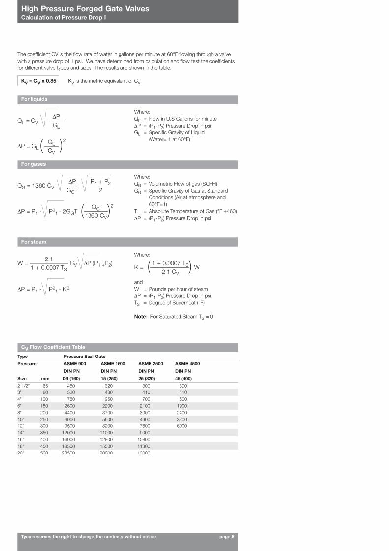
andW = Pounds per hour of steam∆P = (P1-P2) Pressure Drop in psiTS = Degree of Superheat (°F)
Note: For Saturated Steam TS = 0
High Pressure Forged Gate ValvesCalculation of Pressure Drop I
Tyco reserves the right to change the contents without notice page 6
The coefficient CV is the flow rate of water in gallons per minute at 60°F flowing through a valvewith a pressure drop of 1 psi. We have determined from calculation and flow test the coefficientsfor different valve types and sizes. The results are shown in the table.
Kv = Cv x 0.85 Kv is the metric equivalent of Cv
For liquids
QL = CV_____∆P
GL
∆P = GL_____QL
CV( )2
K = _____________ W1 + 0.0007 TS
2.1 CV( )
Where:QL = Flow in U.S Gallons for minute∆P = (P1-P2) Pressure Drop in psiGL = Specific Gravity of Liquid
(Water= 1 at 60°F)
For gases
QG = 1360 CV_____ _______∆PGGT
P1 + P2
2
∆P = P1 - P21 - 2GGT ________QG
1360 CV( )2
Where:QG = Volumetric Flow of gas (SCFH)GG = Specific Gravity of Gas at Standard
Conditions (Air at atmosphere and60°F=1)
T = Absolute Temperature of Gas (°F +460)∆P = (P1-P2) Pressure Drop in psi
For steam
W = _____________ CV ∆P (P1 +P2)2.1
1 + 0.0007 TS
∆P = P1 - P21 - K2
CV Flow Coefficient Table
Type Pressure Seal Gate
Pressure ASME 900 ASME 1500 ASME 2500 ASME 4500
DIN PN DIN PN DIN PN DIN PN
Size mm 09 (160) 15 (250) 25 (320) 45 (400)
2 1/2" 65 450 320 300 3003" 80 520 480 410 4104" 100 780 950 700 5006" 150 2600 2200 2100 19008" 200 4400 3700 3000 240010" 250 6900 5600 4900 320012" 300 9500 8200 7600 600014" 350 12000 11000 900016" 400 16000 12800 1080018" 450 18500 15500 1130020" 500 23500 20000 13000
High Pressure Forged Gate ValvesCalculation of Pressure Drop II
Tyco reserves the right to change the contents without notice page 7
H
GF
E
K
D
A
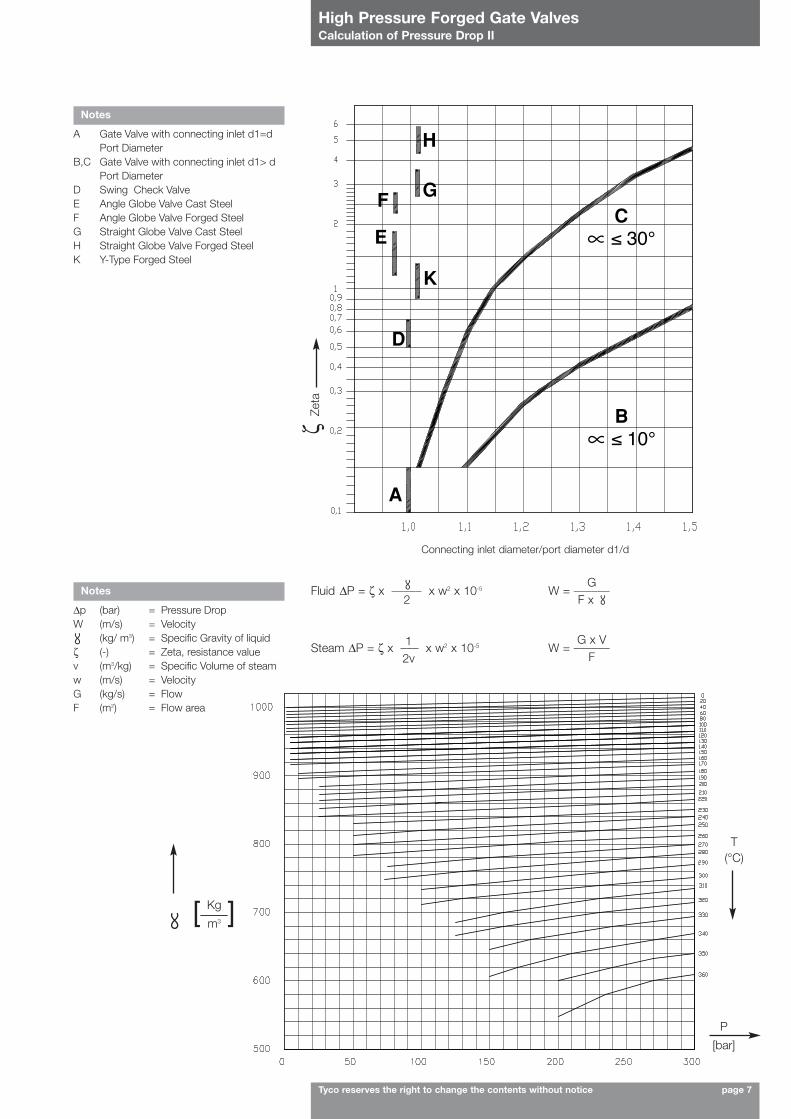
Connecting inlet diameter/port diameter d1/d
Notes
A Gate Valve with connecting inlet d1=dPort Diameter
B,C Gate Valve with connecting inlet d1> dPort Diameter
D Swing Check ValveE Angle Globe Valve Cast SteelF Angle Globe Valve Forged SteelG Straight Globe Valve Cast SteelH Straight Globe Valve Forged SteelK Y-Type Forged Steel
Notes
∆p (bar) = Pressure DropW (m/s) = Velocity
(kg/ m3) = Specific Gravity of liquidζ (-) = Zeta, resistance valuev (m3/kg) = Specific Volume of steamw (m/s) = VelocityG (kg/s) = FlowF (m2) = Flow area
∆P = ζ x _____ x w2 x 10-5Fluid2
12v
W = ______GF x
∆P = ζ x ___ x w2 x 10-5Steam W = ______G x VF
Kg
m3
∝
∝
∝
∝
ζZe
ta
[___]
P
[bar]
T(°C)

High Pressure Forged Gate ValvesDetails of the forged steel pressure seal construction
Tyco reserves the right to change the contents without notice page 8
Standard Characteristics
WedgeWe have designed a new tee-head connection of the wedge. The wedge is now closed aroundthe stem. Flexible split wedge is standard on Forged Valves and wedge’s guide is integral to thebody without any welding. During the stroke, the contact area between wedge and seat rings iswide.The design gives the following coefficients or friction for torque calculation: • µ = 0.4 for wedge or parallel slides• µ = 0.15 for lubricated stem threads
YokeStandard Raimondi materials for yoke nut are ductile iron Ni-Resist D2 or Bronze B148 Gr.B. All yoke nuts are provided with two needle bearings. Every yoke has a lubrication nipple.The yokes are equipped with a connecting flange on the top, ready to assemble gear, motordevices and other accessories.
BonnetAdvanced Pressure Seal design is such that the bonnet is easy to be dismantled. Important : the bonnet must not be dropped into the body cavity
the segment ring is kept in the right position by the safety ring High tightness is achieved with pure graphite gasket rings, covered with a layer of 18.8 on bothsides.
PackingThe new design of packing ensures high tightness with pure graphite pressed rings (min.density1.8 g/cm3) with a ground ring for guiding.The packing chamber is shorter and narrower because the sealing effectiveness improves asoverall packing dimensions decrease. The chamber wall surface roughness is Rz < 5 µm and thesurface roughness of the stem running through the stuffing box is Rz < 1.6 µm.The new design of pure graphite packing also allows vacuum service and protection againstfugitive emissions.
Position IndicatorThe mechanical indicator for open and closed position is standard on Raisteam Valves
Seatrings are welded in
Wedge
Contact area
Seatring
High Pressure Forged Gate ValvesSafety Devices
Tyco reserves the right to change the contents without notice page 9
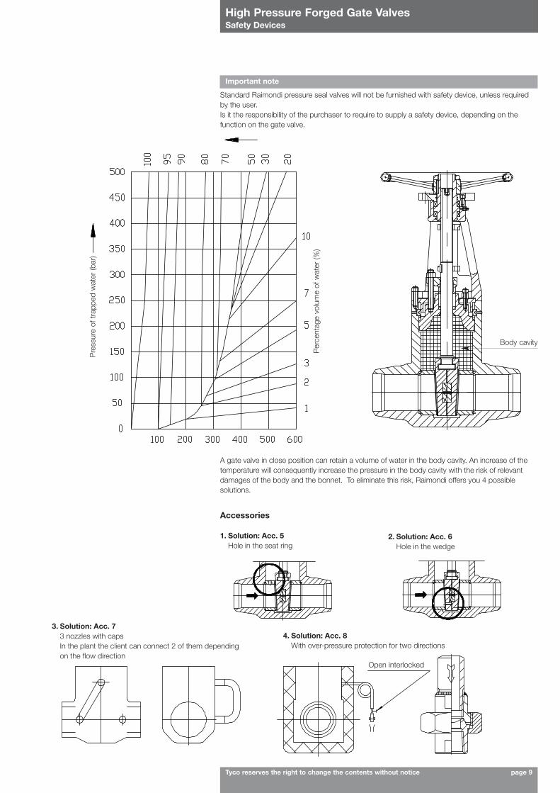
Important note
Standard Raimondi pressure seal valves will not be furnished with safety device, unless requiredby the user.Is it the responsibility of the purchaser to require to supply a safety device, depending on thefunction on the gate valve.
Per
cent
age
volu
me
of w
ater
(%)
Pre
ssur
e of
tra
pped
wat
er (b
ar)
Body cavity
A gate valve in close position can retain a volume of water in the body cavity. An increase of thetemperature will consequently increase the pressure in the body cavity with the risk of relevantdamages of the body and the bonnet. To eliminate this risk, Raimondi offers you 4 possiblesolutions.
Accessories
1. Solution: Acc. 5Hole in the seat ring
3. Solution: Acc. 73 nozzles with capsIn the plant the client can connect 2 of them dependingon the flow direction
4. Solution: Acc. 8With over-pressure protection for two directions
2. Solution: Acc. 6Hole in the wedge
Open interlocked
High Pressure Forged Gate ValvesAccessories (optional)
Tyco reserves the right to change the contents without notice page 10
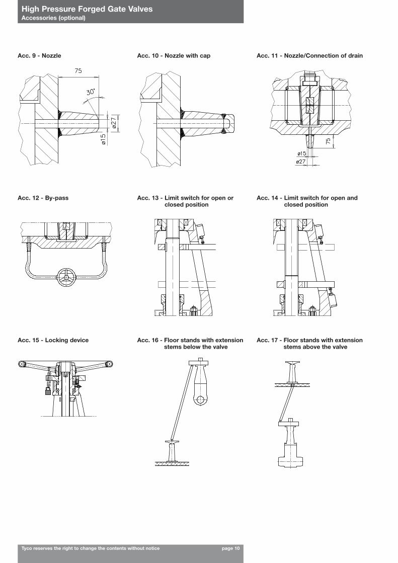
Acc. 9 - Nozzle Acc. 10 - Nozzle with cap Acc. 11 - Nozzle/Connection of drain
Acc. 12 - By-pass Acc. 13 - Limit switch for open orclosed position
Acc. 14 - Limit switch for open andclosed position
Acc. 15 - Locking device Acc. 16 - Floor stands with extensionstems below the valve
Acc. 17 - Floor stands with extensionstems above the valve
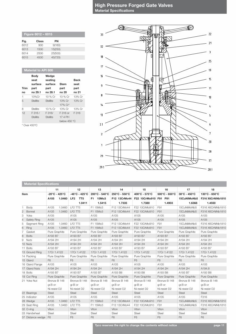
High Pressure Forged Gate ValvesMaterial Specifications
Tyco reserves the right to change the contents without notice page 11
Material Specifications
11 12 13 14 15 16 17 18
Item -20°C - 425°C -46°C - 425°C 200°C - 540°C 250°C - 550°C 400°C - 575°C 500°C - 650°C 38°C - 450°C 130°C - 650°C
A105 1.0460 LF2 TT5 F1 15Mo3 F12 13CrMo44 F22 10CrMo910 F91 P91 15CuNiMoNb5 F316 X6CrNiNb1810
1.0411 1.5415 1.7335 1.7380 1.4903 1.6368 1.4550
1 Body A105 1.0460 LF2 TT5 F1 15Mo3 F12 13CrMo44 F22 10CrMo910 F91 15CuNiMoNb5 F316 X6CrNiNb18102 Bonnet A105 1.0460 LF2 TT5 F1 15Mo3 F12 13CrMo44 F22 10CrMo910 F91 15CuNiMoNb5 F316 X6CrNiNb18103 Yoke A105 A105 A105 A105 A105 A105 A105 A1054 Safety Ring A105 A105 A105 A105 A105 A105 A105 A1055 Segment Ring A105 1.0460 LF2 TT5 F1 15Mo3 F12 13CrMo44 F22 10CrMo910 F91 15CuNiMoNb5 F316 X6CrNiNb18106 Ring A105 1.0460 LF2 TT5 F1 15Mo3 F12 13CrMo44 F22 10CrMo910 F91 15CuNiMoNb5 F316 X6CrNiNb18107 Gasket Pure Graphite Pure Graphite Pure Graphite Pure Graphite Pure Graphite Pure Graphite Pure Graphite Pure Graphite8 Bolts A193 B7 A193 B7 A193 B7 A193 B7 A193 B7 A193 B7 A193 B7 A193 B79 Nuts A194 2H A194 2H A194 2H A194 2H A194 2H A194 2H A194 2H A194 2H10 Nuts A194 2H A194 2H A194 2H A194 2H A194 2H A194 2H A194 2H A194 2H11 Bolts A193 B7 A193 B7 A193 B7 A193 B7 A193 B7 A193 B7 A193 B7 A193 B713 Ground Ring 17Cr 1.4122 17Cr 1.4122 17Cr 1.4122 17Cr 1.4122 17Cr 1.4122 17Cr 1.4122 17Cr 1.4122 17Cr 1.412214 Packing Pure Graphite Pure Graphite Pure Graphite Pure Graphite Pure Graphite Pure Graphite Pure Graphite Pure Graphite15 Gland F6 F6 F6 F6 F6 F6 F6 F616 Gland Flange A105 A105 A105 A105 A105 A105 A105 A10517 Gland Nuts A194 2H A194 2H A194 2H A194 2H A194 2H A194 2H A194 2H A194.818 Bolts A193 B7 A193 B7 A193 B7 A193 B8 A193 B8 A193 B8 A193 B7 A193 B819 Cut Ring Pure Graphite Pure Graphite Pure Graphite Pure Graphite Pure Graphite Pure Graphite Pure Graphite Pure Graphite21 Yoke Nut Bronze B 148 Bronze B 148 Bronze B 148 Bronze B 148 Bronze B 148 Bronze B 148 Bronze B 148 Bronze B 148
gr.B or gr.B or gr.B or gr.B or gr.B or gr.B or gr.B or gr.B orNi-resist D2 Ni-resist D2 Ni-resist D2 Ni-resist D2 Ni-resist D2 Ni-resist D2 Ni-resist D2 Ni-resist D2
22 Bearings Steel Steel Steel Steel Steel Steel Steel Steel25 Indicator A105 A105 A105 A105 A105 A105 A105 F31628 Wedge A105 1.0460 LF2 TT5 F1 15Mo3 F12 13CrMo44 F22 10CrMo910 F91 15CuNiMoNb5 F316 X6CrNiNb181029 Seat Ring A105 1.0460 LF2 TT5 F1 15Mo3 F12 13CrMo44 F22 10CrMo910 F91 15CuNiMoNb5 F316 X6CrNiNb181032 O-ring Viton Viton Viton Viton Viton Viton Viton Viton33 Handwheel Steel Steel Steel Steel Steel Steel Steel Steel37 Distance wedge F6 F6 F6 F6 F6 F6 F6 F6
Figure 6012 – 6015
Fig. Class PN6012 900 9(160)6013 1500 15(250)6014 2500 25(500)6015 4500 45(720)
Material to API 600
Body Wedge seat seating Backsurface surface Stem seat
Trim part part part partno no 29.1 no 28.1 no 20 no 21
1 13%Cr 13 % Cr 13 % Cr 13% Cr5 Stellite Stellite 13% Cr 13% Cr
17% Cr*8 Stellite 13 % Cr 13% Cr 13% Cr12 F 316 / F 316/ F 316 or F 316
Stellite Stellite 17 4 PHbelow 450 °C
* Over 450°C

High Pressure Forged Gate ValvesASME Class 900
Tyco reserves the right to change the contents without notice page 12
Pipeconnection
L B.W. ends L2 RJT flanged ends to ASME B16.10
L1 B.W. ends to ASME B16.10
50 265 x 50 21/2 x 2
216 216 - 515 300 95 55 45 45 65
65 21/2
80 x 65 3 x 21/2216 254 384 515 300 95 55 45 45 65
80 3100 x 80 4 x 3
305 305 384 590 400 135 72 70 70 85
100 4125 x 100 5 x 4
325 356 460 700 500 170 96 105 100 145
125 5150 x 125 6 x 5
375 432 R 770 450 190 121 162 R R
150 6200 x 150 8 x 6
450 508 613 850 450 225 146 220 235 275
175 7200 x 175 8 x 7
525 660 R 950 500 280 167 320 R 420
200 8250 x 200 10 x 8
575 660 740 1050 500 280 188 390 415 560
250 10300 x 250 12 x 10
650 787 841 1460 750 332 236 695 735 810
300 12350 x 300 14 x 12
750 914 968 1650 750 365 280 1000 1160 1200
350 14400 x 350 16 x 14
850 991 1038 1880 850 420 306 1280 1280 1500
400 16450 x 400 18 x 16
950 1092 1140 2100 850 475 342 1700 1700 1950
450 18500 x 450 20 x 18
1050 R R 2320 960 525 380 R R R
500 20600 x 500 24 x 20
1100 R R R R 580 425 R R R
ASME Cl. 900/Pressure Rating 09 (PN 160) - fig. 6012L L1 L2 H V Pipe Conn. Weight (kg)
OD max ID min BW BW2 FL
DN (mm) DN (in.)
d1N x dN d1N x dN
6012 8"(200) 6"(150) 14 5 BWL
Butt weld ends to Raimondi Standard
Trim material
Material Specification
Nominal Size inches (mm)
Connection pipe ends inches (mm)
ASME Class 900, press rating 09 (PN 160)
Gate Valve
Raisteam
Notes
1. All dimensions are in mm.2. BW: weight for buttweld ends type
(Raimondi standard).3. BW2: weight for buttweld ASME
ends type.4. FL: weight for flanged ends type.5. R: available on request.6. The dimensions in bold correspond to our
standard dimensions for 1-piece body.

High Pressure Forged Gate ValvesASME Class 1500
Tyco reserves the right to change the contents without notice page 13
Pipeconnection
L B.W. ends L2 RJT flanged ends to ASME B16.10
L1 B.W. ends to ASME B16.10
50 265 x 50 21/2 x 2
216 216 371 515 300 95 52 45 45 60
65 21/2
80 x 65 3 x 21/2216 254 422 515 300 95 52 45 45 82
80 3100 x 80 4 x 3
305 305 473 590 400 135 68 70 70 115
100 4125 x 100 5 x 4
350 406 549 700 500 170 92 135 150 170
125 5150 x 125 6 x 5
400 559 R 770 500 190 118 220 RR
150 6200 x 150 8 x 6
475 559 711 850 750 225 135 250 280 400
175 7200 x 175 8 x 7
600 711 R 950 750 280 155 380 420 630
200 8250 x 200 10 x 8
625 711 841 1050 750 280 175 480 520 795
250 10300 x 250 12 x 10
725 864 1000 1500 BGR 332 215 890 945 1200
300 12350 x 300 14 x 12
800 991 1146 1680 BGR 365 255 1170 1298 1800
350 14400 x 350 16 x 14
950 1067 1276 1900 BGR 420 280 1330 1420 2300
400 16450 x 400 18 x 16
1000 1194 1407 2200 BGR 475 322 1850 1990 3250
450 18500 x 450 20 x 18
1050 1346 1559 2500 BGR 525 352 R R R
500 20600 x 500 24 x 20
1100 1473 R R R 580 380 R R R
ASME Cl. 1500/Pressure Rating 15 (PN 250) - fig. 6013L L1 L2 H V Pipe Conn. Weight (kg)
OD max ID min BW BW2 FL
DN (mm) DN (in.)
d1N x dN d1N x dN
6013 8"(200) 6"(150) 14 5 BWL
Butt weld ends to Raimondi Standard
Trim material
Material Specification
Nominal Size inches (mm)
Connection pipe ends inches (mm)
ASME Class 1500, press rating 15 (PN 250)
Gate Valve
Raisteam
Notes
1. All dimensions are in mm.2. BW: weight for buttweld ends type
(Raimondi standard).3. BW2: weight for buttweld ASME
ends type.4. FL: weight for flanged ends type.5. R: available on request.6. BGR: bevel gear on request.7. The dimensions in bold correspond to our
standard dimensions for 1-piece body.

High Pressure Forged Gate ValvesASME Class 2500
Tyco reserves the right to change the contents without notice page 14
Pipeconnection
L B.W. ends L2 RJT flanged ends to ASME B16.10
L1 B.W. ends to ASME B16.10
50 265 x 50 21/2 x 2
216 279.4 454 515 300 95 48 45 45 80
65 21/2
80 x 65 3 x 21/2216 330 514 515 300 95 48 45 45 160
80 3100 x 80 4 x 3
350 368 584 590 400 135 65 110 125 168
100 4125 x 100 5 x 4
425 457 683 700 500 170 85 170 180 260
125 5150 x 125 6 x 5
450 533 R 770 500 190 102 280 R R
150 6200 x 150 8 x 6
559 610 927 850 750 225 122 370 405 670
175 7200 x 175 8 x 7
711 762 R 970 750 280 144 450 550 890
200 8250 x 200 10 x 8
725 762 1038 1070 750 280 160 750 795 1480
250 10300 x 250 12 x 10
800 914 1292 1550 BGR 332 198 1120 1245 2000
300 12350 x 300 14 x 12
900 1041 1445 1730 BGR 365 236 1500 1600 3000
350 14400 x 350 16 x 14
1000 1118 R 1980 BGR 420 260 1850 1970 R
400 16450 x 400 18 x 16
1100 1245 R 2230 BGR 475 310 2200 2450 R
450 18500 x 450 20 x 18
R R R 2600 BGR 525 334 R R R
500 20600 x 500 24 x 20
R R R R R 580 365 R R R
ASME Cl. 2500/Pressure Rating 25 (PN 500) - Fig. 6014L L1 L2 H V Pipe Conn. Weight (kg)
OD max ID min BW BW2 FL
DN (mm) DN (in.)
d1N x dN d1N x dN
6014 8"(200) 6"(150) 14 5 BWL
Butt weld ends to Raimondi Standard
Trim material
Material Specification
Nominal Size inches (mm)
Connection pipe ends inches (mm)
ASME Class 2500, press rating 25 (PN 500)
Gate Valve
Raisteam
Notes
1. All dimensions are in mm.2. BW: weight for buttweld ends type
(Raimondi standard).3. BW2: weight for buttweld ASME
ends type.4. FL: weight for flanged ends type.5. R: available on request.6. BGR: bevel gear on request.7. The dimensions in bold correspond to our
standard dimensions for 1-piece body.

High Pressure Forged Gate Valves
Tyco reserves the right to change the contents without notice page 15
Motor Operated Valves
AccessoriesAll Raimondi “Pressure Seal” Valves can be equipped with electrical, pneumatic or hydraulic actuators. Customers are asked, when ordering, tospecify the following requirements that may enable us to supply the correct actuators: 1 Medium 7 Voltage and frequency, pressure of operating fluid (air or hydraulic)2 Working temperature 8 Closing time3 Working pressure 9 Number and type of any auxiliary position indicators (Limit switch)4 Differential pressure across the valve 10 Special classes of insulation5 Nominal diameter of the valve 11 Waterproof or explosion proof6 Type of actuator
Acc. 1 - Type Bevel Gear Acc. 2 - Type Spur Gear
Acc. 3 Acc. 4
Gear Operated Valves
Gear Type 300 600 1100 1101 2300 2301 3800 6000 9000 16000
Connection F10 F14 F16 F25 F25 F25 F30 F35 F35 F40
Gear ratio 1:4,5 1:4,5 1:4,5 1:15,75 1:4,5 1:20,25 1:20,25 1:36 1:40 1:105
Fig. 6012 DNFig. 6013 DNFig. 6014 DNFig. 6015 DN
Dimensions in mm
AA1BCVWeight (Kg)
- 2”- 5” 6” - - 8”- 10” 12” 14”- 20”- 2”- 5” 6” - - 8”- 10” 12” 14”- 20” 24”- 2”- 4” 6” - - 7”- 8” 10” 12” 18”- 20”- 3” - - 6” 8”
180 200 250 315 305 370 420 510 605 770216 253 258 258 338 338 338 374 419 47087 114 141 141 164 164 178 238 243 30356 74 92 92 102 102 115 150 155 215
300 500 800 800 800 500 800 800 800 80010 18 30 40 59 79 115 155 210 320
High Pressure Forged Gate ValvesAccessories
Tyco reserves the right to change the contents without notice page 16
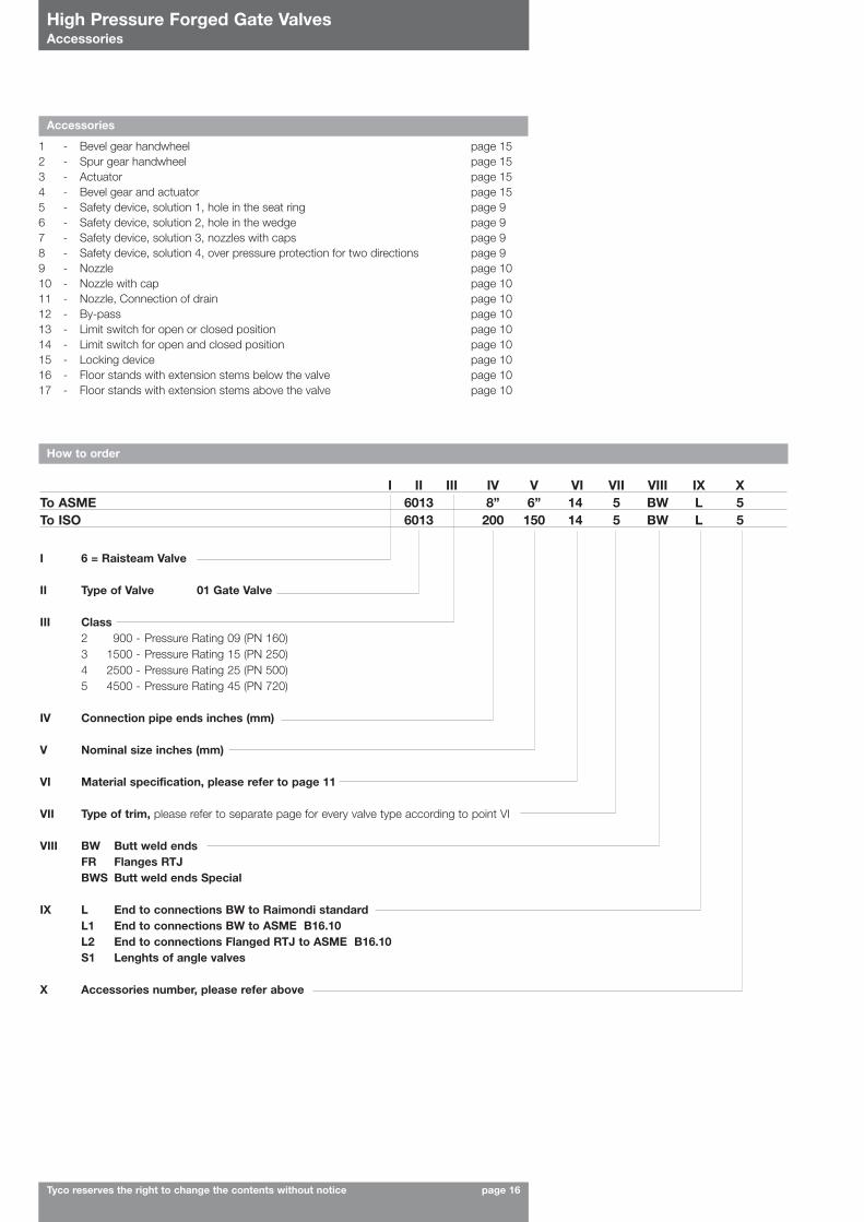
Accessories
1 - Bevel gear handwheel page 15 2 - Spur gear handwheel page 15 3 - Actuator page 15 4 - Bevel gear and actuator page 15 5 - Safety device, solution 1, hole in the seat ring page 9 6 - Safety device, solution 2, hole in the wedge page 9 7 - Safety device, solution 3, nozzles with caps page 9 8 - Safety device, solution 4, over pressure protection for two directions page 9 9 - Nozzle page 10 10 - Nozzle with cap page 10 11 - Nozzle, Connection of drain page 10 12 - By-pass page 10 13 - Limit switch for open or closed position page 10 14 - Limit switch for open and closed position page 1015 - Locking device page 10 16 - Floor stands with extension stems below the valve page 10 17 - Floor stands with extension stems above the valve page 10
How to order
I II III IV V VI VII VIII IX XTo ASME 6013 8” 6” 14 5 BW L 5To ISO 6013 200 150 14 5 BW L 5
I 6 = Raisteam Valve
II Type of Valve 01 Gate Valve
III Class2 900 - Pressure Rating 09 (PN 160)3 1500 - Pressure Rating 15 (PN 250)4 2500 - Pressure Rating 25 (PN 500)5 4500 - Pressure Rating 45 (PN 720)
IV Connection pipe ends inches (mm)
V Nominal size inches (mm)
VI Material specification, please refer to page 11
VII Type of trim, please refer to separate page for every valve type according to point VI
VIII BW Butt weld endsFR Flanges RTJBWS Butt weld ends Special
IX L End to connections BW to Raimondi standardL1 End to connections BW to ASME B16.10L2 End to connections Flanged RTJ to ASME B16.10S1 Lenghts of angle valves
X Accessories number, please refer above