Embed Size (px)
Citation preview
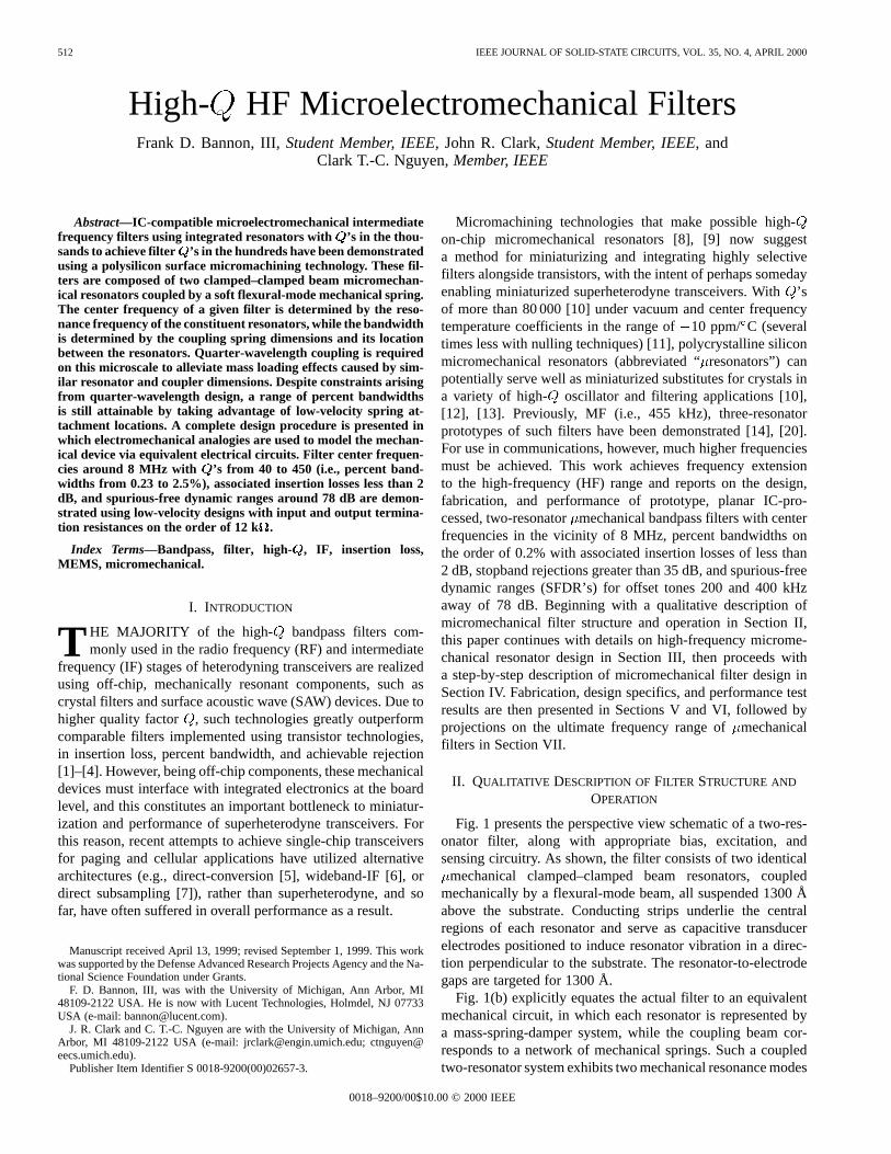
512 IEEE JOURNAL OF SOLID-STATE CIRCUITS, VOL. 35, NO. 4, APRIL 2000
High-Q HF Microelectromechanical FiltersFrank D. Bannon, III, Student Member, IEEE, John R. Clark, Student Member, IEEE, and
Clark T.-C. Nguyen, Member, IEEE
Abstract—IC-compatible microelectromechanical intermediatefrequency filters using integrated resonators with ’s in the thou-sands to achieve filter ’s in the hundreds have been demonstratedusing a polysilicon surface micromachining technology. These fil-ters are composed of two clamped–clamped beam micromechan-ical resonators coupled by a soft flexural-mode mechanical spring.The center frequency of a given filter is determined by the reso-nance frequency of the constituent resonators, while the bandwidthis determined by the coupling spring dimensions and its locationbetween the resonators. Quarter-wavelength coupling is requiredon this microscale to alleviate mass loading effects caused by sim-ilar resonator and coupler dimensions. Despite constraints arisingfrom quarter-wavelength design, a range of percent bandwidthsis still attainable by taking advantage of low-velocity spring at-tachment locations. A complete design procedure is presented inwhich electromechanical analogies are used to model the mechan-ical device via equivalent electrical circuits. Filter center frequen-cies around 8 MHz with ’s from 40 to 450 (i.e., percent band-widths from 0.23 to 2.5%), associated insertion losses less than 2dB, and spurious-free dynamic ranges around 78 dB are demon-strated using low-velocity designs with input and output termina-tion resistances on the order of 12 k.
Index Terms—Bandpass, filter, high- , IF, insertion loss,MEMS, micromechanical.
I. INTRODUCTION
T HE MAJORITY of the high- bandpass filters com-monly used in the radio frequency (RF) and intermediate
frequency (IF) stages of heterodyning transceivers are realizedusing off-chip, mechanically resonant components, such ascrystal filters and surface acoustic wave (SAW) devices. Due tohigher quality factor , such technologies greatly outperformcomparable filters implemented using transistor technologies,in insertion loss, percent bandwidth, and achievable rejection[1]–[4]. However, being off-chip components, these mechanicaldevices must interface with integrated electronics at the boardlevel, and this constitutes an important bottleneck to miniatur-ization and performance of superheterodyne transceivers. Forthis reason, recent attempts to achieve single-chip transceiversfor paging and cellular applications have utilized alternativearchitectures (e.g., direct-conversion [5], wideband-IF [6], ordirect subsampling [7]), rather than superheterodyne, and sofar, have often suffered in overall performance as a result.
Manuscript received April 13, 1999; revised September 1, 1999. This workwas supported by the Defense Advanced Research Projects Agency and the Na-tional Science Foundation under Grants.
F. D. Bannon, III, was with the University of Michigan, Ann Arbor, MI48109-2122 USA. He is now with Lucent Technologies, Holmdel, NJ 07733USA (e-mail: [email protected]).
J. R. Clark and C. T.-C. Nguyen are with the University of Michigan, AnnArbor, MI 48109-2122 USA (e-mail: [email protected]; [email protected]).
Publisher Item Identifier S 0018-9200(00)02657-3.
Micromachining technologies that make possible high-on-chip micromechanical resonators [8], [9] now suggesta method for miniaturizing and integrating highly selectivefilters alongside transistors, with the intent of perhaps somedayenabling miniaturized superheterodyne transceivers. With’sof more than 80 000 [10] under vacuum and center frequencytemperature coefficients in the range of10 ppm/ C (severaltimes less with nulling techniques) [11], polycrystalline siliconmicromechanical resonators (abbreviated “resonators”) canpotentially serve well as miniaturized substitutes for crystals ina variety of high- oscillator and filtering applications [10],[12], [13]. Previously, MF (i.e., 455 kHz), three-resonatorprototypes of such filters have been demonstrated [14], [20].For use in communications, however, much higher frequenciesmust be achieved. This work achieves frequency extensionto the high-frequency (HF) range and reports on the design,fabrication, and performance of prototype, planar IC-pro-cessed, two-resonatormechanical bandpass filters with centerfrequencies in the vicinity of 8 MHz, percent bandwidths onthe order of 0.2% with associated insertion losses of less than2 dB, stopband rejections greater than 35 dB, and spurious-freedynamic ranges (SFDR’s) for offset tones 200 and 400 kHzaway of 78 dB. Beginning with a qualitative description ofmicromechanical filter structure and operation in Section II,this paper continues with details on high-frequency microme-chanical resonator design in Section III, then proceeds witha step-by-step description of micromechanical filter design inSection IV. Fabrication, design specifics, and performance testresults are then presented in Sections V and VI, followed byprojections on the ultimate frequency range ofmechanicalfilters in Section VII.
II. QUALITATIVE DESCRIPTION OFFILTER STRUCTURE AND
OPERATION
Fig. 1 presents the perspective view schematic of a two-res-onator filter, along with appropriate bias, excitation, andsensing circuitry. As shown, the filter consists of two identical
mechanical clamped–clamped beam resonators, coupledmechanically by a flexural-mode beam, all suspended 1300 Åabove the substrate. Conducting strips underlie the centralregions of each resonator and serve as capacitive transducerelectrodes positioned to induce resonator vibration in a direc-tion perpendicular to the substrate. The resonator-to-electrodegaps are targeted for 1300 Å.
Fig. 1(b) explicitly equates the actual filter to an equivalentmechanical circuit, in which each resonator is represented bya mass-spring-damper system, while the coupling beam cor-responds to a network of mechanical springs. Such a coupledtwo-resonator system exhibits two mechanical resonance modes
0018–9200/00$10.00 © 2000 IEEE

BANNON et al.: HIGH- HF MICROELECTROMECHANICAL FILTERS 513
Fig. 1. (a) Perspective view schematic of a two-resonator�mechanical filter,along with the preferred bias, excitation, and sensing circuitry. Significantparasitic elements are also shown in gray. (b) The equivalent mechanical circuit.
with closely spaced frequencies that define the filter passband.The center frequency of the filter is determined primarily bythe frequencies of the constituent resonators, while the spacingbetween modes (i.e., the bandwidth) is determined largely bythe stiffness of the coupling spring. As shown in Fig. 2, eachmode peak corresponds to a distinct, physical mode shape: Inthe lower frequency mode, both resonators vibrate in phase; andin the higher frequency mode, the resonators are 180out ofphase. As will be described, properly chosen termination resis-tors are utilized to flatten the jagged passband shown inFig. 2 to achieve that shown in Fig. 1.
To operate this filter, a dc-bias is applied to the suspendedfilter structure, and an ac input voltage is applied throughresistor to the input electrode (electrode 1), as shown inFig. 1(a). The application of this input creates an-directedelectrostatic force between electrode 1 and the conductive res-onator that induces-directed vibration of the input resonatorwhen the frequency of the input voltage comes within the pass-band of the mechanical filter. This vibrational energy is im-parted to the output resonator via the coupling spring, causingit to vibrate as well. Vibration of the output resonator creates adc-biased, time-varying capacitor between the conductive res-onator and output electrode, which then sources an output cur-rent given by
(1)
where is vertical displacement, with equalto the dc voltage on electrode, and is the changein resonator-to-electrode capacitance per unit displacement atport 2. The current is then directed to resistor , whichconverts the current to an output voltageand, along with ,provides the proper termination impedance required to flattenthe jagged passband of Fig. 2.
Fig. 2. Filter mode shapes and their correspondence to specific peaks in theunterminated frequency characteristic.
In effect, this device takes an electrical input signal, convertsit to a mechanical signal, processes it in the mechanical domain,then reconverts the resulting signal to an electrical output signal,ready for further processing by subsequent electronic stages.
III. HF M ICROMECHANICAL RESONATORS
Because the center frequency of a given mechanical filteris determined primarily by the resonance frequencies of itsconstituent resonators, careful mechanical resonator design isimperative for successful filter implementation. The selected
resonator design must not only be able to achieve the neededfrequency but must also do so with adequate linearity andtunability, and with sufficient .
For many sensor applications, such as accelerometers [15]or gyroscopes [16], the lower the resonance frequency of themechanical structure, the better the sensitivity of the device.Thus, the majority of previous micromachined mechanical de-vices aimed at sensor applications have been designed to res-onate at very low frequencies, below 100 kHz. Designs withlong spring lengths and large masses are common for these ap-plications, and techniques that extend linearity and displace-ment amplitude, such as interdigitated comb-capacitive trans-ducers and folded-beam suspensions [9], are often used.
Such designs, however, are impractical for applications inthe HF range, and beyond. In order to maximize resonance fre-quency, governed by the general expression
(2)
the effective resonator spring stiffnessmust be maximized,while its effective mass is minimized. The optimum HF res-onator design should thus avoid the increased mass of a combstructure and the stiffness reduction of a folded-flexure. For thisreason, this work utilizes the simple clamped-clamped beamresonator shown in Fig. 3 under a typical bias and excitationconfiguration.
The resonance frequency of this clamped-clamped beam de-pends upon many factors, including geometry, structural ma-terial properties, stress, the magnitude of the applied dc-biasvoltage , and surface topography. Accounting for these while
514 IEEE JOURNAL OF SOLID-STATE CIRCUITS, VOL. 35, NO. 4, APRIL 2000
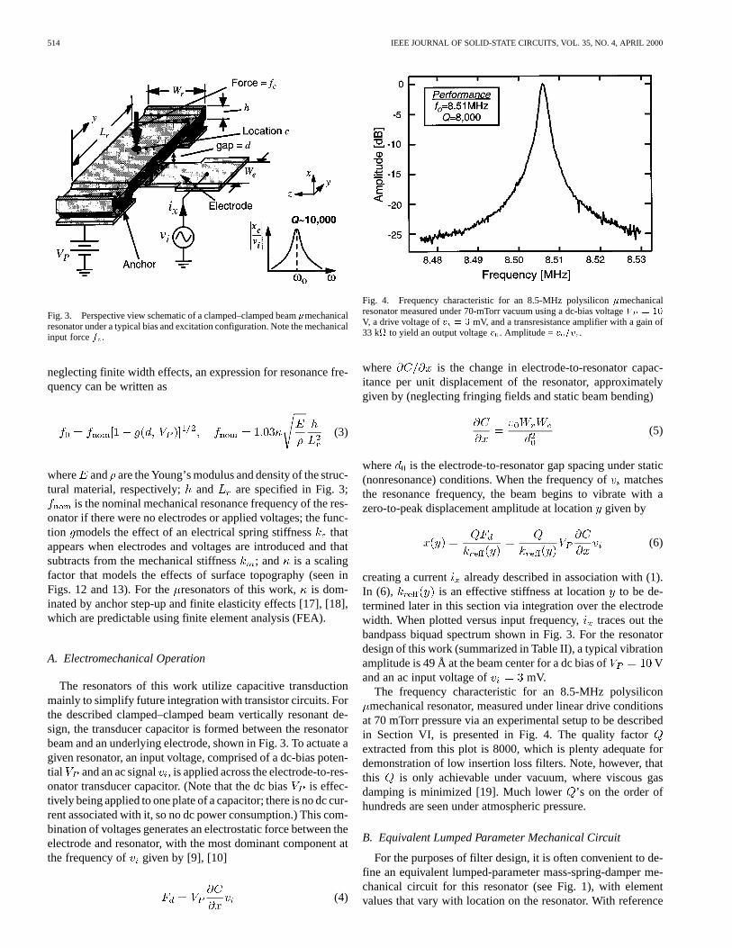
Fig. 3. Perspective view schematic of a clamped–clamped beam�mechanicalresonator under a typical bias and excitation configuration. Note the mechanicalinput forcef .
neglecting finite width effects, an expression for resonance fre-quency can be written as
(3)
where and are the Young’s modulus and density of the struc-tural material, respectively; and are specified in Fig. 3;
is the nominal mechanical resonance frequency of the res-onator if there were no electrodes or applied voltages; the func-tion models the effect of an electrical spring stiffnessthatappears when electrodes and voltages are introduced and thatsubtracts from the mechanical stiffness; and is a scalingfactor that models the effects of surface topography (seen inFigs. 12 and 13). For theresonators of this work, is dom-inated by anchor step-up and finite elasticity effects [17], [18],which are predictable using finite element analysis (FEA).
A. Electromechanical Operation
The resonators of this work utilize capacitive transductionmainly to simplify future integration with transistor circuits. Forthe described clamped–clamped beam vertically resonant de-sign, the transducer capacitor is formed between the resonatorbeam and an underlying electrode, shown in Fig. 3. To actuate agiven resonator, an input voltage, comprised of a dc-bias poten-tial and an ac signal , is applied across the electrode-to-res-onator transducer capacitor. (Note that the dc biasis effec-tively being applied to one plate of a capacitor; there is no dc cur-rent associated with it, so no dc power consumption.) This com-bination of voltages generates an electrostatic force between theelectrode and resonator, with the most dominant component atthe frequency of given by [9], [10]
(4)
Fig. 4. Frequency characteristic for an 8.5-MHz polysilicon�mechanicalresonator measured under 70-mTorr vacuum using a dc-bias voltageV = 10
V, a drive voltage ofv = 3 mV, and a transresistance amplifier with a gain of33 k to yield an output voltagev . Amplitude =v =v .
where is the change in electrode-to-resonator capac-itance per unit displacement of the resonator, approximatelygiven by (neglecting fringing fields and static beam bending)
(5)
where is the electrode-to-resonator gap spacing under static(nonresonance) conditions. When the frequency ofmatchesthe resonance frequency, the beam begins to vibrate with azero-to-peak displacement amplitude at locationgiven by
(6)
creating a current already described in association with (1).In (6), is an effective stiffness at locationto be de-termined later in this section via integration over the electrodewidth. When plotted versus input frequency,traces out thebandpass biquad spectrum shown in Fig. 3. For the resonatordesign of this work (summarized in Table II), a typical vibrationamplitude is 49 Å at the beam center for a dc bias of Vand an ac input voltage of mV.
The frequency characteristic for an 8.5-MHz polysiliconmechanical resonator, measured under linear drive conditions
at 70 mTorr pressure via an experimental setup to be describedin Section VI, is presented in Fig. 4. The quality factorextracted from this plot is 8000, which is plenty adequate fordemonstration of low insertion loss filters. Note, however, thatthis is only achievable under vacuum, where viscous gasdamping is minimized [19]. Much lower ’s on the order ofhundreds are seen under atmospheric pressure.
B. Equivalent Lumped Parameter Mechanical Circuit
For the purposes of filter design, it is often convenient to de-fine an equivalent lumped-parameter mass-spring-damper me-chanical circuit for this resonator (see Fig. 1), with elementvalues that vary with location on the resonator. With reference

BANNON et al.: HIGH- HF MICROELECTROMECHANICAL FILTERS 515
Fig. 5. Resonator cross-sectional schematic for frequency-pulling andimpedance analysis.
to Fig. 5, the equivalent mass at a locationon the resonator isgiven by [20]
(7)where
(8)
and for the fundamental mode,is the peak kinetic energy in the system, is the ve-
locity at location , and dimensional parameters are given inFig. 5. The equivalent spring stiffness follows readily from (2)and (7) and is given by
(9)
where is the radian resonance frequency of the beam. Last,the damping factor is given by
(10)
where
(11)
is the mechanical stiffness of the resonator alone, without the in-fluence of applied voltages and electrodes to be discussed next,and is the quality factor of the resonator under the sameconditions.
C. Voltage-Tunable Electrical Stiffness
As indicated in (3), where is seen to be a function of dc-biasvoltage , the resonance frequency of this device is tunable viaadjustment of [8], and this can be used advantageously toimplement filters with tunable center frequencies, or to correctfor passband distortion caused by finite planar fabrication tol-erances. The dc-bias dependence of resonance frequency arisesfrom a -dependent electrical spring constantthat subtractsfrom the mechanical spring constant of the system, loweringthe overall spring stiffness , thus lowering the res-onance frequency according to the expression
(12)
where and denote values at a particular location (usuallythe beam center location), and the quantity must beobtained via integration over the electrode width due to thelocation dependence of .
The electrical spring stiffness is generated by the nonlineardependence of electrode-to-resonator gap capacitance ondisplacement and is dependent very strongly upon the elec-trode-to-resonator gap spacing. At a specific location cen-tered on an infinitesimally small width of the electrode, thedifferential in electrical stiffness is given by [21]
(13)
where the electrode-to-resonator gap distanceis now seen toalso be location dependent, since the beam bends somewhat dueto the dc bias applied between the electrode and resonator.Recognizing that for the fundamental mode the static and dy-namic stiffnesses are virtually the same, and assuming a staticbending shape due to the distributed dc force defined by thefunction , the gap distance can be expressed as
(14)where is the static electrode-to-resonator gap with V.In (14), the second term represents the static displacement ofthe resonator towards the electrode at a particular location,evaluated by integration over the width of the electrode, from
to . In this work the electrode is centered withthe resonator beam center, and thus and
. Since the desired variable appears onboth sides of (14), one of them within an integral, (14) is bestsolved by first assuming on the right side, solvingfor on the left, then using this function again on the right,iterating until converges. In addition, for most cases (14)is not overly sensitive to the function , sogiven by (8) can be substituted for with little differ-ence. It should be noted that more rigorous versions of (14) areattainable through strict static analysis, but these often take theform of polynomial expansions and are less intuitive than (14).
The quantity may now be found by integrating overthe electrode width and is given by
(15)
Given the dependencies of (13)–(15), and assuming a set valueof , designing the resonator of Fig. 3 for a specific resonancefrequency amounts to setting geometric dimensions, , and
via CAD layout, since all other variables are determined atthe outset by fabrication technology.
D. Pull-In Voltage
When the applied dc-bias voltage is sufficiently large, cat-astrophic failure of the device ensues, in which the resonatorbeam is pulled down onto the electrode. This leads to either de-struction of the device due to excessive current passing throughthe now shorted electrode-to-resonator path or at least a removalof functionality if a dielectric layer (e.g., an oxide or nitride) is

516 IEEE JOURNAL OF SOLID-STATE CIRCUITS, VOL. 35, NO. 4, APRIL 2000
Fig. 6. Equivalent circuit for a�mechanical resonator with both electrical(voltagev ) and mechanical (forcef ) inputs and outputs.
TABLE IMECHANICAL-TO-ELECTRICAL
CORRESPONDENCE IN THECURRENT ANALOGY
present above the electrode to prevent electrical contact betweenit and the conductive resonator beam.
Unlike previous low-frequency micromechanical structures[8], [15], the attractive electrostatic force between the electrodeand this HF resonator that incites pulldown now acts againsta very large distributed stiffness that must be integrated overthe electrode area to accurately predict the pulldown voltage
. Thus, previously used closed-form expressions for[21]based on lumped parameter analysis are no longer applicable.Rather, for this resonator, the procedure for determiningentails finding the that sets the resonance frequency equalto zero, and thus, with reference to (12), amounts to setting (15)equal to unity and solving for the variable.
E. Small-Signal Electrical Equivalent Circuit
To conveniently model and simulate the impedance behaviorof this mechanical resonator in an electromechanical circuit,an electrical equivalent circuit is needed [8], [22], [23]. Asshown in Fig. 3, both electrical and mechanical inputs and out-puts are possible for this device, so the equivalent circuit mustbe able to model both. In addition, for physical consistencyfrom both transducer and noise perspectives, a circuit modelthat directly uses the lumped mechanical elements summarizedby (7)–(10) is preferred. Fig. 6 presents the equivalent circuitused in this work, in which transformers model both electricaland mechanical couplings to and from the resonator, whichitself is modeled by a coreLCRcircuit—the electrical analogyto a mass-spring-damper system—with element values corre-sponding to actual values of mass, stiffness, and damping asgiven by (7)–(10). In this circuit, the current electromechanicalanalogy is utilized, summarized in Table I.
When looking into the electrode port of the equivalent res-onator circuit of Fig. 6, a transformedLCRcircuit is seen, withelement values given by
(16)
where the subscript denotes the electrode location at the verycenter of the resonator beam (i.e., at ). An expres-sion for the electromechanical transformer turns ratiocan beobtained via an impedance analysis yielding the motional re-sistance seen across the electrode-to-resonator gap at res-onance. Pursuant to this, the voltage-to-displacement transferfunction at a given location (see Fig. 5) at resonance is firstfound using phasor forms of (4)—(6), (8), and (9) and inte-grating over the electrode width to yield
(17)
Using the phasor form of (1), the series motional resistanceseen looking into the drive electrode is then found to be
(18)
Inserting (17), factoring out , and extractingyields
(19)Note that the effective integrated stiffness defined in (6) can alsobe extracted from (17), yielding
(20)The transformer turns ratio in Fig. 6 models the mechan-
ical impedance transformation achieved by mechanically cou-pling to the resonator at a location displaced from its center.As will be seen, such coupling will be required when imple-menting filters with two or more resonators. Expressed in termsof a stiffness ratio, the equation for the mechanical transformerturns ratio when coupling at a distancefrom an anchor takesthe form
(21)
Finally, for the equivalent circuit of Fig. 6, it should be notedthat the damping constant is not inherently a function of theelectrical stiffness . Thus, when expressed in terms of theoverall stiffness of the system, the of the resonator mustbe adjusted so that retains its original value given by (10). Interms of and , then, expressions for take on the form
(22)
where
(23)
Note that the effective resonator quality factoris dependentupon the electrical spring stiffness, and thus is also a functionof the dc-bias voltage . In this paper, the variable denotes

BANNON et al.: HIGH- HF MICROELECTROMECHANICAL FILTERS 517
that defined by (23), while is reserved for zero-bias con-ditions.
IV. FILTER DESIGN
Despite the use of vibratingmechanical resonators ratherthan transistor-based orLCR biquads, the network topologiesfor the mechanical filters of this work differ very little fromthose of their purely electronic counterparts, and in principalcan be designed at the system level via a procedure derivedfrom well-known, coupled resonator ladder filter synthesis tech-niques. In particular, given the equivalentLCRelement valuesfor a prototype mechanical resonator, it is possible to synthe-size a mechanical filter entirely in the electrical domain, con-verting to the mechanical domain only as the last step. However,although possible, such a procedure is not recommended, sinceknowledge and ease of design in both electrical and mechanicaldomains can greatly reduce the effort required.
The design procedure for the two-resonator micromechanicalfilter of this work can be itemized as follows.
1) Design and establish themechanical resonator proto-type to be used, choosing necessary geometries for theneeded frequency and insuring that enough electrode-to-resonator transducer coupling is provided to allow for pre-determined termination resistor values.
2) Choose a manufacturable value of coupling beam widthand design coupling beam(s) corresponding to a
“quarter-wavelength” of the filter center frequency.3) Determine the coupling location(s) on the resonators cor-
responding to the filter bandwidth of interest.4) Generate a complete equivalent circuit for the overall
filter and verify the design using a circuit simulator.Each of the above steps will now be expanded.
A. Micromechanical Resonator Design
The mechanical resonators comprising the filter are prefer-ably designed to be identical, each with the same stand-aloneresonance frequency. Design equations governing the dimen-sions and bias voltages required to achieve a given frequencyhave already been presented in Section III.
In addition to determining the center frequency of the filter,the resonator design also dictates the termination resistors re-quired for passband flattening. As withLC-ladder filters, the de-scribed mechanical filters must be terminated with the properimpedance values. Without proper termination, the resonator
’s are too large, and the filter passband consists of distinctpeaks of selectivity, as seen in Fig. 2. In order to flatten the pass-band between the peaks, the’s of the constituent resonators(more precisely, of the end resonators) must be reduced, and thiscan be done by terminating the filter with resistors. In Fig. 1, re-sistors and serve this function. The required value oftermination resistance for amechanical filter with center fre-quency and bandwidth is given by
(24)
where is the unloaded quality factor of the constituent res-onators, = , refers to the end resonator in question,
Fig. 7. Equivalent mechanical circuit for the two-resonator filter of Fig. 1(a)using a coupling beam of length less than an eighth of a wavelength of theoperating frequency.
and is a normalized parameter obtained from a filter cook-book [24]. For the common case where , (24) be-comes
(25)
Of the variables in (25), the electromechanical coupling factoris often the most convenient to adjust for a desired value of
termination resistance. Thus, considering both (19) and (25),termination impedance requirements and bias voltagelimitations often dictate the electrode-to-resonator gap spacingand overlap for a particular resonator design.
B. Coupling Beam Design
If each resonator is designed to have the same resonance fre-quency, then the passband of the overall filter will be centeredaround this frequency. The coupling spring acts to effectivelypull the resonator frequencies apart, creating two closely spacedresonance modes that constitute the ends of the filter passband.For a given filter center frequency and bandwidth , the re-quired coupling beam spring constant can be found using theexpression [20], [24]
(26)
where is the resonator stiffness at the coupling location andis the normalized coupling coefficient between resonator
tanks for a given filter type (i.e., Butterworth, Chebyshev, etc.)[24]. The needed value of coupling spring constant is thenattained by proper choice of coupling beam geometry using ex-pressions to be determined.
The design of the coupling beam is complicated by the factthat the beam itself has finite mass. In particular, for the case ofmicroscale filters, the coupling beam mass is on the same orderas that of the resonator beams. Unless accounted for, this beammass can add to the masses of the adjacent resonators, therebychanging their individual resonance frequencies as dictated by(2), and in turn, changing the center frequency of the filter ordistorting its passband if it uses more than two resonators. Thisis depicted in Fig. 7, which shows a specific case where each res-onator effectively takes on half the mass of the coupling spring,leading to an overall shift in filter center frequency as seen undersimulation.
Although instructive, Fig. 7 actually only describes the spe-cial case where the coupling beam length is less than an eighthof the acoustic wavelength corresponding to the frequencyof operation. For this special case, the coupling beam can bemodeled by the lumped mass-spring system shown. In general,however, especially at high frequencies, the coupling beam ismore accurately modeled by an acoustic transmission line—the

518 IEEE JOURNAL OF SOLID-STATE CIRCUITS, VOL. 35, NO. 4, APRIL 2000
(a)
(b)
Fig. 8. (a) Coupling beam under forcesf andf with corresponding velocityresponses. (b) General transmission lineT -model for the coupling beam.
mechanical analog to the familiar electrical transmission line.For this mechanical transmission line, adistributedmechanicalcircuit is more applicable, and the amount of coupling beammass and stiffness effectively seen by the resonators adjacentto the coupling beam actually vary with the beam dimensionsand the frequency of operation. For the purposes of filterdesign, Fig. 8 presents a general transmission line model forthe coupling beam, consisting of a network of mechanicalimpedances.
Pursuant to determination of the values of, , andin Fig. 8, the mechanical impedance behavior of the couplingbeam as seen by the adjacent (attached) resonators can be con-veniently modeled via an impedance matrix of the form [25]
(27)
where
(28)
(29)
(30)
(31)
, , is the widthof the coupling beam, other needed dimensions are given inFig. 8(a), and we have assumed that rotation of the couplingbeam at the connection points is not significant. For cases whererotation is important, the matrix in (27) becomes larger [25] butthe solution methods remain similar.
Equating the circuit of Fig. 8(b) to a chain network describedby (27) [24], then solving for the series and shunt impedancesin terms of chain matrix elements, yields
(32)
Fig. 9. Simplified equivalent circuit for the micromechanical filter of Fig. 1using a quarter-wavelength coupling beam.
and
(33)
In order to minimize susceptibility to beam geometric varia-tions (i.e., mass variations) caused by finite layout or fabricationtolerances, the coupling beam should be designed to correspondto a quarter-wavelength of the filter center frequency. This canbe achieved by choosing coupling beam dimensions such thatthe series and shunt arm impedances of Fig. 8(b) take on equaland opposite values, and thus cancel in each mesh. By inspec-tion of (32) and (33), and take on equal and oppositevalues when
(34)
Using the selected value of [in step 2) of Section IV] and as-suming that is set by technology, (34) can be solved for thethat corresponds to an effective quarter-wavelength of the oper-ating frequency. With quarter-wavelength coupler dimensions,the impedances of Fig. 8(b) are given by
(35)
and
(36)
From these equations, with the help of (29) and (31) for expan-sion purposes, the stiffness of a quarter-wavelength couplingbeam is found to be
(37)
It should be noted that in addition to decreasing the overallfilter susceptibility to variations in coupling beam geometry,the use of quarter-wavelength coupling beams also allows theuse of identical resonators in the filter. This is perhaps best il-lustrated in the electrical domain, in the context of the simpli-fied filter network shown in Fig. 9, obtained using the currentelectromechanical analogy of Table I on the lumped mechan-ical circuit of Fig. 1(b). Here,LCR circuits represent the res-onators and a capacitive-network models the coupling beam.As a result of filter synthesis, one property of this network is thateach mesh with all others open-circuited must resonate at thecenter frequency of the filter [24]. Upon inspection ofMesh

BANNON et al.: HIGH- HF MICROELECTROMECHANICAL FILTERS 519
Fig. 10. Simulated plot ofQ and percent bandwidth versus couplinglocationl along the length of a resonator beam.
1, withMesh2 open-circuited, the capacitors andare seen to cancel, leaving only the and
of the mechanical resonator to contribute to the frequencyof Mesh1. The same applies forMesh2 with Mesh1 open-cir-cuited. Thus, when quarter-wavelength coupling beams are uti-lized, all of the resonators comprising the filter must be iden-tical, each resonating at the center frequency of the filter.
The availability of designs using identical resonators isespecially important for the case of the planar-fabricated mi-cromechanical filters of this work, since matched resonators aremuch easier to achieve in a planar process than are resonatorswith varying, specific frequencies—i.e., matching tolerancesare much better than absolute tolerances in planar processes.
C. Coupling Location (Low-Velocity Coupling)
The maximum overall filter quality factor ( )attainable via a mechanical filter is proportional to the ratio ofthe resonator and coupling beam spring constants andis given by using (26)
(38)
where is percent bandwidth. For the case ofmacroscopicmechanical filters, can be made quite large, becausethe resonators are often much bigger and thicker than their asso-ciated coupling springs [20]. On the other hand, inmechanicalfilters, the resonators and couplers are usually of similar size,and thus, the ratio is limited. This, then, limits the at-tainable (or percent bandwidth).
A novel method for attaining greater takes advan-tage of the fact that the dynamic spring constant of aclamped–clamped beam is larger at locations closer to theanchor points—i.e., it is larger at points moving with lowervelocity at resonance. This can be seen easily from (7) and (9),which give resonator mass and stiffness as a function of beamlocation. Thus, by coupling the beams closer to the anchorpoints, rather than at the centers of resonator beams, higher
can be attained, and thus higher can be achieved,even when the resonators and coupling springs have similarsizes.
Fig. 10 illustrates this point with a plot of versus cou-pling location along the length of a resonator beam. As shown,
is highest near the anchor points where the velocity islowest, and smallest at the beam center, where the velocity is
maximized. Since is merely the reciprocal of percent band-width, Fig. 10 also shows that the bandwidth of the filter can beset by appropriately selecting the location at which the resonatorand the coupling beam meet. This is a very convenient feature,since it allows the use of a set coupling beam geometry. In otherwords, the coupling beam need not be redesigned to accommo-date filters with different bandwidths; only one quarter-wave-length coupling beam need be designed—with a specific length,width, and thickness—and filter bandwidth can be varied bychanging only the resonator-to-coupler attachment location.
D. Equivalent Circuit and Design Verification
Although useful for the purpose at hand, Fig. 9 presents onlya simplified electrical equivalent circuit for the two-resonator
mechanical filter of this work. In particular, a mereLCRcircuitgreatly oversimplifies the equivalent circuit for themechanicalresonators used in the filter because it models the device as aone-port. The filter resonators are actually two-port devices, oneport being at the electrode and the other being at the location ofspring coupling, and forces applied to each of these ports com-bine to generate the overall response of a givenresonator. Withthis in mind, Fig. 11 presents a more suitable equivalent circuitfor the overall filter, where each resonator is now modeled bythe circuit of Fig. 6, and mechanical impedance transformationsto the coupling spring are now conveniently modeled via trans-formers with turns ratios . For the reader’s convenience, ex-pressions for all of the circuit elements are summarized alongwith the circuit schematic in Fig. 11.
V. FABRICATION
A polysilicon surface micromachining technology similarto previously reported versions [9], [10], except for the veryimportant distinction that the sacrificial oxide thickness in thisprocess is only 1300 Å, was used to fabricate themechanicalfilter of this work. In this process, a series of film depositionsand lithographic patterning steps—essentially identical tosimilar steps used in planar IC fabrication technologies—areutilized to first achieve the cross-section shown in Fig. 12(a).Here, patterned phosphorus-doped polysiliconI/O electrodesand interconnect (3000 Å thick) are covered by a 1300-Å-thicklayer of sacrificial LPCVD silicon dioxide, except at portionswet-etched to serve as anchors for eventual resonators. A2- m-thick structural polysilicon film is then deposited viaLPCVD at 585 C and made conductive via a POClgas dopingstep. 5000 Å of LPCVD SiO then follows to serve first as adiffusion barrier against dopant loss during a subsequent 1-h1050 C stress and dopant distribution anneal, then as a hardmask during patterning of the structural polysilicon layer viaa chlorine-based, high-density-plasma reactive ion etch (RIE)[Fig. 12(b)]. Note that throughout the back end of this process,the sacrificial oxide layer supports the structural polysiliconmaterial during deposition, patterning, and annealing, anddefines the electrode-to-resonator gap spacing. In the finalstep of the process, the wafer is dipped into a solution ofhydrofluoric acid, which etches away the sacrificial oxide layerwithout significantly attacking the polysilicon structural mate-rial. This leaves the free-standing structure shown in Fig. 12(c)

520 IEEE JOURNAL OF SOLID-STATE CIRCUITS, VOL. 35, NO. 4, APRIL 2000
Fig. 11. Complete equivalent circuit for the micromechanical filter of Fig. 1, modeling both quarter-wavelength coupling beam design and low-velocity couplinglocation. Expressions for the elements are also included.
Fig. 12. Cross-sections depicting the fabrication sequence used to achieve themicromechanical filter: (a) polysilicon electrode and interconnect layers under a1300-Å-thick sacrificial oxide, (b) required film layers and masks needed duringresonator patterning in a chlorine-based RIE etch, and (c) resulting free-standingbeam following a release etch in hydrofluoric acid.
free to move in several dimensions if necessary. The releaseetch is followed by extensive cleaning, including a 10-min dipin a solution of HSO and H O (i.e., piranha) and often asupercritical CO clean [27], to remove etch by-products andother residuals from the thin electrode-to-resonator gap.
Micromechanical filters with center frequencies from 3 to15 MHz were designed using the procedures detailed in Sec-tions III and IV, then fabricated using the above polysilicon sur-face micromachining technology. Fig. 13 shows the scanningelectron micrograph (SEM) of a fabricated filter with designspecifics summarized in Table II.
VI. EXPERIMENTAL RESULTS
Upon inspection and initial biasing of the completed devices,two immediate observations were made: 1) none of the devicesstuck to the substrate after a standard, wet HF release and 2)pull-in voltages [8], [21] were high, on the order of 50 V, evenfor target resonator-to-electrode gap spacings of only 1300 Å.Both of these features result from the high spring stiffnessesrequired to achieve HFmechanical resonators. The near im-
Fig. 13. SEM of a fabricated 7.81-MHz two-resonator micromechanical filter.
munity to stiction [29] and the high pull-in voltages contraststrongly with those of lower frequency applications, such asaccelerometers [15], and suggests that yield loss due to thesemechanisms should be substantially less for HF MEMS usedfor communications.
Since the quality factor of mechanical resonators is largeonly under vacuum, resonators and filters were tested usinga custom-built vacuum chamber. This chamber featuredfeedthroughs for connection to external instrumentation, aswell as internal supports for circuit board inclusion. Withthis setup, the termination resistors shown in Fig. 1(a) plusbuffering electronics to drive coax to external instrumentationcan be placed within the vacuum chamber, alongside packaged
mechanical devices, with minimal parasitic interference.Using a mechanical pump, the minimum achievable pressureof this system was 40 mTorr.
The SEM and frequency characteristic for an 8.5-MHzparallel-plate driven, polysilicon mechanical resonator mea-sured using the above apparatus with no termination resistorsand using a transresistance amplifier was already presentedin Fig. 4. It should be mentioned that the of 8000 in thismeasurement is not as high as seen in previous polysilicon
mechanical resonators, for which’s higher than 80 000 havebeen demonstrated [30]. Measurements of other resonatorssuggest that the lower for this resonator can be attributed tothe use of a POClgas process to dope the resonator, which hasbeen found to decrease theof polysilicon resonators belowthat of ion-implant-doped orin situ-doped ones [32]. Anchordissipation may also be limiting the. Nevertheless, a of8000 is certainly high enough to achieve extremely selectivebandpass filters with minimal insertion loss.
In actual testing of filters, is provided by either amatching network to an appropriate load, or by a physical

BANNON et al.: HIGH- HF MICROELECTROMECHANICAL FILTERS 521
TABLE IIHF MICROMECHANICAL FILTER SUMMARY
resistor with value in shunt with the output node thatconverts to a voltage that can then be buffered to subsequentcircuit loads. Alternatively, transresistance detection can be
Fig. 14. Measured spectrum for a terminated 7.81-MHz�mechanical filterwith excessive input/output shunt capacitance. Here,Q = 435.
implemented via an op-amp-based inverting amplifier using aninput resistor with value .
A. Micromechanical Filter Testing and Model Evaluation
The measured spectrum for a terminated 7.81 MHz two-res-onator mechanical filter is shown in Fig. 14 (solid curve). Thebandwidth of this filter is 18 kHz, which is very close to thedesign value. The insertion loss is only 1.8 dB, which is impres-sive for a bandpass filter with a percent bandwidth of 0.23%( ) and which can be attributed to the high ofthe constituent mechanical resonators. Designed and measured
mechanical filter characteristics are summarized in Table II.It should be noted that although the analytical design calls for19.6-k termination resistors, only 12.2-kresistors were usedin the actual measurement to minimize phase lags caused byboard-level parasitic capacitance.
In addition to the measured frequency response, Fig. 14 alsopresents a simulated spectrum (dotted line) using the equivalentcircuit described by Fig. 11 with element values derived fromthe “simulated” column of Table II and summarized in Table III.This simulation attempts to mimic the measured frequency char-acteristic in the passband. As such, it includes shunt parasitic ca-pacitors fF at the input and output nodes (see Fig. 1)to model board-level parasitics that interact with termination re-sistors and generate increased passband ripple. It should benoted, however, that a few adjustments were necessary to at-tain the degree of matching shown. In particular, note that thetarget gap spacing of 1300 Å was not used to generate the “sim-ulated” column in Table II, nor the values in Table III. Rather, alarger gap spacing of 1985 Å was used that accounts for deple-tion in the resonator beam induced by the-induced electricfield between the nondegenerately doped n-type beam and then-type electrode. This value of gap spacing was semiempiricallydetermined by matching measured plots of resonatorversus
with simulations based on (12), using and as fittingparameters.
In addition, as indicated in boldface in Table II, the couplinglocation was adjusted to match bandwidths, and the resonator
and the filter termination resistance were adjusted to

522 IEEE JOURNAL OF SOLID-STATE CIRCUITS, VOL. 35, NO. 4, APRIL 2000
TABLE IIIHF �MECHANICAL FILTER CIRCUIT ELEMENT VALUES
match the measured insertion loss. In particular, the value ofneeded to match the simulated insertion loss and passband
ripple was 14.5 k , not the 12.2 k actually used for the mea-surement.
The adjustment isnotunreasonable,since thecouplingbeamhasafinitewidthof0.75m,andtheexactcouplinglocation isnotnecessarily at the center of the coupling beam but could be any-where along its finite width. Furthermore, torsional motions ofthe coupling beam can also influence the actual mechanical cou-pling, thus changing the effective. The adjustment in seenin Table II is also plausible, since a small number of resonatorsexhibited lower than the 8000 measured in Fig. 4. The smalldeviation in also should not be alarming, given some uncer-tainty in the actual gap distance for this process.
Note that although the simulation matches the measurementvery well in the passband, it deviates substantially in its transitionto the stopband. In particular, the measured curve features losspoles not modeled by the theory of Section IV that substantiallyimprove the shape factor of the filter. The loss poles in Fig. 14result largely from action of the feedthrough capacitor(see Fig. 1) in a similar fashion to the introduction of loss polesvia bridging capacitors in crystal filter design [26]. In the presentexperiment, is actually a parasitic element; i.e., losspoles were introduced inadvertently. For fully integrated filters,in which mechanics and circuits are fabricated side-by-sideon a single chip, parasitic capacitors are expected to be muchsmaller. In this case, the feedthrough capacitor can thenbe purposefully designed into the filter if loss poles are desired.
B. Low-Velocity Coupling
The low-velocity coupling design strategy detailed in Sec-tion IV was verified by measuring the bandwidths of filters asa function of coupling spring location along the resonator beamlength. Fig. 15(a) and (b) compares the measured frequencycharacteristics for two filters, one coupled at m toachieve (0.53) coupling and another at m toachieve a lower coupling velocity of . The filterbandwidth clearly changes as the coupling location changes. Inparticular, the (0.12) coupled filter exhibits a percent band-width of 0.23%, which is much smaller than the 2.5% of its
(a)
(b)
Fig. 15. Frequency characteristics for (a) a (0.53)v coupled filter and (b)a (0.12)v coupled filter, both measured under 70-mTorr pressure.
(0.53) coupled counterpart and which verifies the utilityof low velocity coupling for implementing high- filters on themicroscale. It should be noted that the termination resistors re-quired to flatten the passband of the (0.53) -coupled filter inFig. 15(a) were too large for off-chip testing, where relativelylarge parasitic capacitors introduce passband distorting phaselags. Thus, only the unterminated spectrum is shown, and thebandwidth is taken as the frequency range between mode peaks.The actual terminated bandwidth will be slightly larger than this.In addition, the difference in the center frequencies of the twospectra arises because a smaller value ofwas used to mea-sure Fig. 15(a).
C. Passband Tuning
Although theirmatchingtolerances are fairly good, planarfabrication technologies often exhibit rather poorabsolutetol-erances. For example, integrated capacitors in CMOS technolo-gies can often be matched to 0.2%, but their absolute values candeviate from designed values by as much as 20% [33]. From themicromechanical perspective, the absolute resonance frequen-cies of micromechanical resonators can deviate from their de-signed values [using (12)] by several percent—as much as 3%in the University of Michigan’s Solid-State Electronics Labo-ratory. Such frequency deviations are caused by any number ofprocess-related phenomena, such as widthvariations due toetch undercutting, thicknessvariations due to film depositionrate inconsistencies, and residual stress in deposited films, toname a few. As with planar IC technologies, these variationsstill seem to be uniform in small areas, so resonator-to-resonatorfrequency matching tolerances are fairly good, on the order of0.4%.
BANNON et al.: HIGH- HF MICROELECTROMECHANICAL FILTERS 523
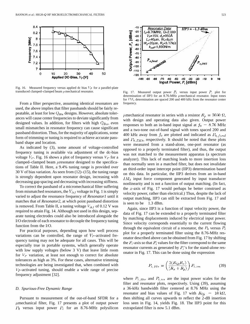
Fig. 16. Measured frequency versus applied dc biasV for a parallel-platetransduced clamped–clamped beam�mechanical resonator.
From a filter perspective, assuming identical resonators areused, the above implies that filter passbands should be fairly re-peatable, at least for low designs. However, absolute toler-ances will cause center frequencies to deviate significantly fromdesigned values. In addition, for filters with high , evensmall mismatches in resonator frequency can cause significantpassband distortion. Thus, for the majority of applications, someform of trimming or tuning is required to achieve accurate pass-band shape and location.
As indicated by (3), some amount of voltage-controlledfrequency tuning is available via adjustment of the dc-biasvoltage . Fig. 16 shows a plot of frequency versus for aclamped–clamped beamresonator designed to the specifica-tions of Table II. Here, a 9.4% tuning range is provided over30 V of bias variation. As seen from (12)–(15), the tuning rangeis strongly dependent upon resonator design, increasing withdecreasing gap spacing and decreasing with increasing stiffness.
To correct the passband of a micromechanical filter sufferingfrom mismatched resonators, the voltage in Fig. 1 is simplyvaried to adjust the resonance frequency ofResonator1until itmatches that ofResonator2, at which point passband distortionis removed. From Table II, a tuning voltage of 0.12 V wasrequired to attain Fig. 14. Although not used in this design, sep-arate tuning electrodes could also be introduced alongside theI/O electrode of each resonator to decouple the frequency tuningfunction from the I/O.
For practical purposes, depending upon how well processvariations can be controlled, the range of -activated fre-quency tuning may not be adequate for all cases. This will beespecially true in portable systems, which generally operatewith low supply voltages (below 3 V) that leave little roomfor variation, at least not enough to correct for absolutetolerances as high as 3%. For these cases, alternative trimmingtechnologies are being investigated that, when combined with
-activated tuning, should enable a wide range of precisefrequency adjustment [32].
D. Spurious-Free Dynamic Range
Pursuant to measurement of the out-of-band SFDR for amechanical filter, Fig. 17 presents a plot of output power
versus input power for an 8.76-MHz polysilicon
Fig. 17. Measured output powerP versus input powerP plot fordetermination of IIP3 for an 8.76-MHz�mechanical resonator. Input tonesfor IM determination are spaced 200 and 400 kHz from the resonator centerfrequency.
mechanical resonator in series with a resistor ,with design and operating data also given. Output powerresponses to both an in-band input signal at MHzand a two-tone out-of-band signal with tones spaced 200 and400 kHz away from are plotted and indicated asand , respectively. It should be noted that these plotswere measured from a stand-alone, one-port resonator (asopposed to a properly terminated filter), and thus, the outputwas not matched to the measurement apparatus (a spectrumanalyzer). This lack of matching leads to more insertion lossthan normally seen in a matched filter, but does not invalidatean third-order input intercept point (IIP3) determination basedon this data. In particular, the IIP3 derives from an in-band
input force component generated by input transducernonlinearity and is not a function of output matching. (In fact,the -axis of Fig. 17 would perhaps be better construed asvelocity power, rather than electrical.) Thus, despite the lack ofoutput matching, IIP3 can still be extracted from Fig. 17 andis seen to be 1.3 dBm.
Again, since IIP3 is a function of input velocity power, thedata of Fig. 17 can be extended to a properly terminated filterby matching displacements induced by electrical input power.Since velocity corresponds essentially to the current flowingthrough the equivalent circuit of a resonator, theversusplot for a properly terminated filter using the 8.76-MHz res-onator described above can be obtained from Fig. 17 by shiftingthe -axis so that values for the filter correspond to the sameresonator currents as generated by’s for the stand-alone res-onator in Fig. 17. This can be done using the expression
(39)
where and are the input power scales for thefilter and resonator plots, respectively. Using (39), assuminga 36-kHz bandwidth filter centered at 8.76 MHz using theresonator and bias values of Fig. 17 with k ,then shifting all curves upwards to reflect the 2-dB insertionloss seen in Fig. 14, yields Fig. 18. The IIP3 point for thisextrapolated filter is now 5.1 dBm.

524 IEEE JOURNAL OF SOLID-STATE CIRCUITS, VOL. 35, NO. 4, APRIL 2000
Fig. 18. Output powerP versus input powerP plot for determination of IIP3for an 8.76-MHz�mechanical filter (extrapolated from Fig. 17).
The out-of-band SFDR (with tones 200 and 400 kHz offsetfrom the filter center frequency) can now be determined via theexpression [31]
SFDR IIP3 SNR (40)
where all quantities are in decibels, SNRis the required min-imum signal-to-noise ratio, and is the input-referred noisepower, given for this filter by
(41)
where dBm is the thermal noise power deliveredby into a matched load, is the insertion loss of the filter,and is the filter bandwidth. Note that noise associated withBrownian motion of the mechanical filter structure is modeledby thermal noise in its ’s [10], and is included in thecomponent of (41). For dB and SNR dB,(40) yields an SFDR dB.
VII. FREQUENCYRANGE OF APPLICABILITY
The ultimate frequency range of the described microme-chanical resonators is of great interest and is presently a topicunder intense study. From a purely geometric standpoint, thefrequency range of micromechanical resonators can extendwell into the gigahertz range. For example, the dimensionsof a clamped–clamped beam resonator required to attain afrequency of 1 GHz are (referring to Fig. 3 and assuming
V) approximately m, m, andm, where finite-element analysis should be used to
account for width and anchoring effects. This frequency canalso be attained by longer beams vibrating in higher modes.Thus, according to analytical and finite-element prediction,frequencies into the gigahertz range are geometrically possible.
Geometry, however, is only one of many important consid-erations. The applicable frequency range of micromechanicalresonators will also be a function of several other factors, in-cluding:
1) quality factor, which may change with frequency for agiven material, depending upon frequency-dependent en-ergy loss mechanisms [28];
2) series motional resistance (cf., Fig. 11), which must beminimized to allow impedance matching with other
transceiver components and to alleviate filter passbanddistortion due to parasitics [14], [34], [35];
3) absolute and matching tolerances of resonance frequen-cies, which will both be functions of the fabrication tech-nology and of frequency trimming or tuning strategies[32];
4) stability of the resonance frequency against temperaturevariations, mass loading (e.g., by contaminant molecules[36]), aging, and other environmental phenomena.
Each of the above phenomena is currently under study. In par-ticular, assuming adequate vacuum can be achieved, the ulti-mate quality factor will be strongly dependent upon the materialtype, and even the manufacturing process. For example, surfaceroughness or surface damage during fabrication may play a rolein limiting quality factor. In fact, preliminary results comparingthe quality factor achievable in boron-source-doped polysiliconstructures (which exhibit substantial pitting of the poly surface)versus implant-doped ones, indicate that the latter exhibit al-most an order of magnitude higher at frequencies near 10MHz. Another loss mechanism that may become more impor-tant with increasing frequency is loss to the substrate throughanchors. More balanced tuning fork designs could alleviate thismechanism.
From a filter design perspective, the practical frequencyrange is limited by electromechanical coupling. In particular,electromechanical coupling largely determines the value ofrequired to terminate a given filter, and thus, dictates matchingrequirements, power-handling capability, and susceptibility topassband distorting shunt parasitic capacitance. To satisfypresent-day impedance matching requirements, a smallisoften required, which from (24) necessitates a small value of
in the resonators making up a given filter. From (18), this ismost conveniently achieved by reducing the electrode-to-res-onator gap spacing , increasing the electrode-to-resonatorarea overlap area , or increasing the dc biasvoltage applied to the resonator. For practical purposes,is limited by the total beam length (which is in turn dictated by
), and is limited by the available power supply or by thehighest voltage achievable via charge pumping in the circuittechnology being used. Reduction of the electrode-to-resonatorgap spacing, perhaps down to 200 Å rather than 1300 Å, and theuse of different dopings for the resonator and electrode (e.g.,p-type resonator, n-type electrode) to prevent depletion-basedgap increases, may be the most practical methods for reducing
. For the filter of Fig. 13, a gap spacing of Å wouldallow the use of 1-k termination resistors with V.
Because the gap spacing for the above HF filter is definedby an oxide spacer thickness, it can be made very small, on theorder of tens to hundreds of angstroms. For this reason, the min-imum gap spacing is likely not determined by process limita-tions, but rather by dynamic range and linearity considerations.In particular, for a given displacement amplitude, a decrease ingap spacing leads to an increase in capacitive transducer non-linearity.
This can most readily be seen in an expression for nonlineardistortion. An approximate expression for the magnitude of thein-band force component at arising from third-order inter-modulation of two out-of-band interferers at

BANNON et al.: HIGH- HF MICROELECTROMECHANICAL FILTERS 525
and can be derived by considering nonlineari-ties in the input capacitive transducer. Assuming that resonatordisplacements are small enough that stiffening nonlinearity canbe neglected, such a derivation yields
(42)
where , , and
(43)
where is the 3-dB frequency at the upperedge of the filter passband. For theresonator in series with
of Fig. 17, (4) and (42) combine to predict anIIP3 dBm, which is close to the measured value. Forthe parameters used in the filter example of Fig. 18, (40)–(42)yield IIP3 dBm and SFDR dB—very close to mea-sured/extracted values.
Equation (42) indicates that third-order intermodulation forcecomponents can be reduced by increasing the electrode-to-res-onator gap spacing and the effective integrated resonatorstiffness , while decreasing the electrode-to-resonatoroverlap area and the applied dc bias . Unfortunately, asseen from (18) and (24), these adjustments also increase therequired value of termination resistance . Thus, for the filterdesign of this work, there is a tradeoff between linearity (i.e.,dynamic range) and the ability to match to small impedances.Although small impedances are not normally required at IFfrequencies, they are often needed at RF in the transmit path,e.g., to load power amplifiers. Nevertheless, even withreductions to maintain adequately low , (42) predicts fairlygood dynamic range at higher frequencies. For example, for ahypothetical 200-kHz bandwidth, 70-MHzmechanical filterwith k , and using resonators with ,
m, m, m, m,Å, N/m, and for
V , (40), (42), and the design equations of Sections IIIand IV yield (with input tones offset 400 and 800 kHz from)IIP3 dBm and an out-of-band SFDR of 78 dB.
From a broader perspective, the above linearity versusimpedance tradeoff amounts essentially to a power-handlinglimitation. Some of the more promising methods for enhancingthe power-handling capability of micromechanical filtersinclude alternative transducer configurations (e.g., more linearcapacitive transduction, or piezoelectric transduction) and var-ious system-level solutions (e.g., paralleling micromechanicalfilters), both of which are the subject of current research.
VIII. C ONCLUSIONS
Surface-micromachined, polysilicon, high- mechanicalbandpass filters in the HF range have been designed, fabri-cated, and tested with particular attention to design limitationscaused by miniaturization of resonator and spring elements.
In particular, coupling beam masses are comparable to thoseof resonators on this microscale, so mass loading effects areamplified in this domain. In the absence of proper designmethodologies, such mass loading can generate center fre-quency shifts and distortion in the filter passband. To suppressthis effect, quarter-wavelength coupling springs are utilized,but these place constraints on the values of coupler stiffnessthat then limit the percent bandwidth attainable by microscalemechanical filters using a rigid geometry. A novel techniquebased on low-velocity coupling was introduced and demon-strated that alleviates percent bandwidth restrictions and allowsthe realization of high- mechanical filters.
High- performance was demonstrated for both singleresonators and filters in the HF range, leading to impressively
low insertion loss in small percent bandwidth micromechanicalfilters. Passband distortion caused by finite planar processtolerances was alleviated via a voltage-controlled frequencypulling capability arising from effective electrical stiffnessesthat add to the mechanical stiffnesses of the resonator beams.Such frequency tuning or trimming methods are expectedto become increasingly important as dimensions shrink toaccommodate higher VHF and UHF frequencies.
ACKNOWLEDGMENT
The authors would like to thank the staff of the University ofMichigan’s Solid-State Laboratory for fabrication support.
REFERENCES
[1] H. Khorramabadi and P. R. Gray, “High-frequency CMOS con-tinuous-time filters,” IEEE J. Solid-State Circuits, vol. SC-19, pp.939–948, Dec. 1984.
[2] R. A. Sykes, W. L. Smith, and W. J. Spencer, “Monolithic crystal filters,”in 1967 IEEE Int. Conv. Rec. pt. II, Mar. 20–23, pp. 78–93.
[3] R. C. Rennick, “An equivalent circuit approach to the design and anal-ysis of monolithic crystal filters,”IEEE Trans. Sonic Ultrason., vol.SU-20, pp. 347–354, Oct. 1973.
[4] C. K. Campbell,Surface Acoustic Wave Devices for Mobile WirelessCommunications. New York, NY: Academic, 1998.
[5] A. A. Abidi, “Direct-conversion radio transceivers for digital commu-nications,”IEEE J. Solid-State Circuits, vol. 30, pp. 1399–1410, Dec.1995.
[6] J. C. Rudell, J.-J. Ou, T. B. Cho, G. Chien, F. Brianti, J. A. Weldon, andP. R. Gray, “A 1.9-GHz wide-band IF double conversion CMOS receiverfor cordless telephone applications,”IEEE J. Solid-State Circuits, vol.32, pp. 2071–2088, Dec. 1997.
[7] D. H. Shen, C.-M. Hwang, B. B. Lusignan, and B. A. Wooley, “A900-MHz RF front-end with integrated discrete-time filtering,”IEEE J.Solid-State Circuits, vol. 31, pp. 1945–1954, Dec. 1996.
[8] R. T. Howe and R. S. Muller, “Resonant microbridge vapor sensor,”IEEE Trans. Electron Devices, vol. ED-33, pp. 499–506, 1986.
[9] W. C. Tang, T.-C. H. Nguyen, and R. T. Howe, “Laterally driven polysil-icon resonant microstructures,”Sensors Actuators, vol. 20, pp. 25–32,1989.
[10] C. T.-C. Nguyen and R. T. Howe, “An integrated CMOS micromechan-ical resonator high-Q oscillator,” IEEE J. Solid-State Circuits, vol. 34,pp. 440–445, Apr. 1999.
[11] , “Microresonator frequency control and stabilization using an in-tegrated micro oven,” inDig. Tech. Papers 7th Int. Conf. Solid-StateSensors and Actuators (Transducers’93), Yokohama, Japan, June 7–10,1993, pp. 1040–1043.
[12] C. T.-C. Nguyen, “Frequency-selective MEMS for miniaturized low-power communication devices,”IEEE Trans. Microwave Theory Tech.,vol. 47, no. 8, pp. 1486–1503, Aug. 1999.
[13] C. T.-C. Nguyen, L. P. B. Katehi, and G. M. Rebeiz, “Micromachineddevices for wireless communications,”Proc. IEEE, vol. 86, pp.1756–1768, Aug. 1998.

526 IEEE JOURNAL OF SOLID-STATE CIRCUITS, VOL. 35, NO. 4, APRIL 2000
[14] K. Wang and C. T.-C. Nguyen, “High-order micromechanical electronicfilters,” in Proc. 1997 IEEE Int. Micro Electro Mechanical SystemsWorkshop, Nagoya, Japan, Jan. 26–30, 1997, pp. 25–30.
[15] B. E. Boser and R. T. Howe, “Surface micromachined accelerometers,”IEEE J. Solid-State Circuits, vol. 31, pp. 366–375, Mar. 1996.
[16] N. Yazdi, F. Ayazi, and K. Najafi, “Micromachined inertial sensors,”Proc. IEEE, vol. 86, pp. 1640–1659, Aug. 1998.
[17] S. Bouwstra and B. Geijselaers, “On the resonance frequencies of mi-crobridges,” inDig. Tech. Papers 6th Int. Conf. Solid-State Sensors andActuators, San Francisco, CA, June 24–27, 1991, pp. 538–542.
[18] Q. Meng, M. Mehregany, and R. L. Mullen, “Theoretical modelling ofmicrofabricated beams with elastically restrained supports,”J. Micro-electromech. Syst., vol. 2, no. 3, pp. 128–137, Sept. 1993.
[19] W. E. Newell, “Miniaturization of tuning forks,”Science, vol. 161, pp.1320–1326, Sept. 1968.
[20] R. A. Johnson,Mechanical Filters in Electronics. New York, NY:Wiley, 1983.
[21] H. Nathanson, W. E. Newell, R. A. Wickstrom, and J. R. Davis Jr., “Theresonant gate transistor,”IEEE Trans. Electron Devices, vol. ED-14, pp.117–133, Mar. 1967.
[22] H. A. C. Tilmans, “Equivalent circuit representation of electro-mechanical transducers: I. Lumped-parameter systems,”J. Micromech.Microeng., vol. 6, pp. 157–176, 1996.
[23] H. A. C. Tilmans and R. Legtenberg, “Electrostatically driven vacuum-encapsulated polysilicon resonators: Part II. Theory and performance,”Sensors and Actuators, vol. A45, pp. 67–84, 1995.
[24] A. I. Zverev,Handbook of Filter Synthesis. New York: Wiley, 1967.[25] M. Konno and H. Nakamura, “Equivalent electrical network for the
transversely vibrating uniform bar,”J. Acoust. Soc. Amer., vol. 38, pp.614–622, Oct. 1965.
[26] M. S. Lee, “Polylithic crystal filters with loss poles at finite frequencies,”in Proc. 1975 IEEE Int. Symp. Circuits and Syst., Apr. 21–23, 1975, pp.297–300.
[27] G. T. Mulhern, D. S. Soane, and R. T. Howe, “Supercritical carbondioxide drying of microstructures,” inProc. 7th Int. Conf. Solid-StateSensors and Actuators (Transducers’93), Yokohama, Japan, June 1993,pp. 296–299.
[28] V. B. Braginsky, V. P. Mitrofanov, and V. I. Panov,Systems with SmallDissipation. Chicago, IL: Univ. Chicago Press, 1985.
[29] C. H. Mastrangelo and C. H. Hsu, “Mechanical stability and adhesionof microstructures under capillary forces—Part I: Basic theory,”J. Mi-croelectromech. Syst., vol. 2, no. 1, pp. 33–43, 1993.
[30] C. T.-C. Nguyen and R. T. Howe, “Quality factor control for microme-chanical resonators,” inTech. Dig. IEEE Int. Electron Devices Meeting,San Francisco, CA, Dec. 14–16, 1992, pp. 505–508.
[31] B. Razavi,RF Microelectronics. Englewood Cliffs, NJ: Prentice-Hall,1998.
[32] K. Wang, A.-C. Wong, W.-T. Hsu, and C. T.-C. Nguyen, “Fre-quency-trimming andQ-factor enhancement of micromechanicalresonators via localized filament annealing,” inDig. Tech. Papers 1997Int. Conf. Solid-State Sensors and Actuators, Chicago, IL, June 16–19,1997, pp. 109–112.
[33] R. Gregorian and G. C. Temes,Analog MOS Integrated Circuits forSignal Processing. New York: Wiley, 1986.
[34] F. D. Bannon III. and C. T.-C. Nguyen, “High frequency microelec-tromechanical IF filters,” inTech. Dig. 1996 IEEE Electron DevicesMeeting, San Francisco, CA, Dec. 8–11, 1996, pp. 773–776.
[35] J. R. Clark, A.-C. Wong, and C. T.-C. Nguyen, “Parallel-resonator HFmicromechanical bandpass filters,” inDig. Tech. Papers 1997 Int. Conf.Solid-State Sensors and Actuators, Chicago, IL, June 16–19, 1997, pp.1161–1164.
[36] C. T.-C. Nguyen and R. T. Howe, “Design and performance of mono-lithic CMOS micromechanical resonator oscillators,” inProc. 1994IEEE Int. Frequency Control Symp., Boston, MA, May 31 –June 3,1994, pp. 127–134.
Frank D. Bannon III (S’94–M’98) received the B.S.degree from Pennsylvania State University, Univer-sity Park, in 1995 and the M.S. degree from the Uni-versity of Michigan, Ann Arbor, in 1997, both in elec-trical engineering.
Since 1997, he has been a Member of TechnicalStaff at Lucent Technologies’ Bell Laboratories,Holmdel, NJ. His interests are in RF and microwaveanalog circuit design and MEMS for optics andsignal-processing applications.
Mr. Bannon is a member of HKN and Phi KappaPhi.
John R. Clark (S’99) was born in Dearborn, MI, in1974. He received the B.S. and M.S. degrees in elec-trical engineering from the University of Michigan,Ann Arbor, in 1996 and 1998, respectively, where heis currently pursuing the Ph.D. degree.
His research is on high-frequency micromechan-ical filters.
Clark T.-C. Nguyen (S’90–M’95) was born inAustin, TX, on March 29, 1967. He received theB.S., M.S., and Ph.D. degrees from the Universityof California at Berkeley in 1989, 1991, and1994, respectively, all in electrical engineering andcomputer sciences.
In 1995, he joined the Faculty of the University ofMichigan, Ann Arbor, where he is currently an Assis-tant Professor in the Department of Electrical Engi-neering and Computer Science. From 1995 to 1997,he was a Member of the National Aeronautics and
Space Administration (NASA)’s New Millennium Integrated Product Develop-ment Team on Communications, which roadmaps future communications tech-nologies for NASA use into the turn of the century. His research interests focusupon microelectromechanical systems and include integrated micromechanicalsignal processors and sensors, merged circuit/micromechanical technologies,RF communication architectures, and integrated circuit design and technology.
Prof. Nguyen received the 1938E Award for Research and Teaching Excel-lence from the University of Michigan in 1998 and an EECS DepartmentalAchievement Award in 1999. He was a Finalist for the 1998 Discover Maga-zine Technological Innovation Awards. Together with his students, he receivedthe Roger A. Haken Best Student Paper Award at the 1998 IEEE InternationalElectron Devices Meeting and the Judges Award for Best Paper at the 1998 IEEEMTT-S International Microwave Symposium. He recently Cochaired the Work-shop on Microelectromechanical Devices for RF Systems at the 1999 IEEEMTT-S Symposium.