Embed Size (px)
Citation preview

High-resolution measurements of the DT neutron spectrum using new CD foils in theMagnetic Recoil neutron Spectrometer (MRS) on the National Ignition FacilityM. Gatu Johnson, J. A. Frenje, R. M. Bionta, D. T. Casey, M. J. Eckart, M. P. Farrell, G. P. Grim, E. P.Hartouni, R. Hatarik, M. Hoppe, J. D. Kilkenny, C. K. Li, R. D. Petrasso, H. G. Reynolds, D. B. Sayre, M. E.Schoff, F. H. Séguin, K. Skulina, and C. B. Yeamans Citation: Review of Scientific Instruments 87, 11D816 (2016); doi: 10.1063/1.4959946 View online: http://dx.doi.org/10.1063/1.4959946 View Table of Contents: http://scitation.aip.org/content/aip/journal/rsi/87/11?ver=pdfcov Published by the AIP Publishing Articles you may be interested in The magnetic recoil spectrometer (MRSt) for time-resolved measurements of the neutron spectrum at theNational Ignition Facility (NIF) Rev. Sci. Instrum. 87, 11D806 (2016); 10.1063/1.4959164 Measurements of fuel and ablator ρR in Symmetry-Capsule implosions with the Magnetic Recoil neutronSpectrometer (MRS) on the National Ignition Facilitya) Rev. Sci. Instrum. 85, 11E104 (2014); 10.1063/1.4886418 High-resolution spectroscopy used to measure inertial confinement fusion neutron spectra on Omega(invited)a) Rev. Sci. Instrum. 83, 10D919 (2012); 10.1063/1.4742926 Probing high areal-density cryogenic deuterium-tritium implosions using downscattered neutron spectrameasured by the magnetic recoil spectrometera) Phys. Plasmas 17, 056311 (2010); 10.1063/1.3304475 First measurements of the absolute neutron spectrum using the magnetic recoil spectrometer at OMEGA(invited)a) Rev. Sci. Instrum. 79, 10E502 (2008); 10.1063/1.2956837
Reuse of AIP Publishing content is subject to the terms at: https://publishing.aip.org/authors/rights-and-permissions. Download to IP: 198.125.180.115 On: Fri, 12 Aug
2016 18:20:03
REVIEW OF SCIENTIFIC INSTRUMENTS 87, 11D816 (2016)
High-resolution measurements of the DT neutron spectrum using new CDfoils in the Magnetic Recoil neutron Spectrometer (MRS) on the NationalIgnition Facility
M. Gatu Johnson,1,a) J. A. Frenje,1 R. M. Bionta,2 D. T. Casey,2 M. J. Eckart,2 M. P. Farrell,3G. P. Grim,2 E. P. Hartouni,2 R. Hatarik,2 M. Hoppe,3 J. D. Kilkenny,3 C. K. Li,1R. D. Petrasso,1 H. G. Reynolds,3 D. B. Sayre,2 M. E. Schoff,3 F. H. Séguin,1 K. Skulina,2and C. B. Yeamans21Massachusetts Institute of Technology, Cambridge, Massachusetts 02139, USA2Lawrence Livermore National Laboratory, Livermore, California 94550, USA3General Atomics, San Diego, California 92186, USA
(Presented 7 June 2016; received 5 June 2016; accepted 2 July 2016;published online 9 August 2016)
The Magnetic Recoil neutron Spectrometer (MRS) on the National Ignition Facility measures theDT neutron spectrum from cryogenically layered inertial confinement fusion implosions. Yield, arealdensity, apparent ion temperature, and directional fluid flow are inferred from the MRS data. Thispaper describes recent advances in MRS measurements of the primary peak using new, thinner,reduced-area deuterated plastic (CD) conversion foils. The new foils allow operation of MRS atyields 2 orders of magnitude higher than previously possible, at a resolution down to ∼200 keVFWHM. Published by AIP Publishing. [http://dx.doi.org/10.1063/1.4959946]
I. INTRODUCTION
Neutron spectrometers on the National Ignition Facility1
(NIF) are fielded in five locations distributed around the targetchamber to diagnose fuel assembly, stagnation, and thermo-nuclear burn in cryogenically layered DT Inertial ConfinementFusion (ICF) implosions.2 From the measured neutron spectra,the key implosion parameters of yield (YDT), apparent iontemperature (Tion), and areal density (ρR) are inferred.3 TheρR is inferred from the measured down-scatter ratio (dsr), i.e.,the ratio of neutrons in the energy ranges 10-12 MeV and13-15 MeV. Directional velocity of the burning fuel is deter-mined from the mean energy of the primary DT neutron peak.4
Comparing results between different lines-of-sight (LOS) pro-vides information about implosion symmetry,5 believed tobe one of the primary remaining challenges on the road toachieving thermonuclear ignition in the laboratory. Recently,understanding manifestations in the shape of the primary DTneutron spectrum of burn dynamics and flows in the implo-sions has emerged as an important path toward a clearer pictureof the assembled fuel at peak compression.6 This path imposesstringent requirements on the precision of primary DT-neutronpeak measurements, which requires high-resolution spectrom-eters. At the same time, yields for the best-performing NIFimplosions have recently climbed to nearly 1016,7 with theexpectation of further increases by more than an order ofmagnitude as implosion performance improves further; this
Note: Contributed paper, published as part of the Proceedings of the 21stTopical Conference on High-Temperature Plasma Diagnostics, Madison,Wisconsin, USA, June 2016.a)Author to whom correspondence should be addressed. Electronic mail:
additionally imposes the requirement on the spectrometers ofbeing capable of operating at high yields.
One of the NIF neutron spectrometers, the MagneticRecoil neutron Spectrometer (MRS),8–12 uniquely measuresthe neutron spectrum from NIF DT implosions using the recoiltechnique combined with a magnet. In the MRS, a fraction ofthe neutrons generated in a NIF experiment scatter elasticallyin a deuterated plastic conversion foil 26 cm from targetchamber center (TCC). Forward-scattered recoil deuterons areselected by an aperture in front of a permanent Nd–Fe–B mag-net behind the target chamber wall. These recoil deuterons aremomentum separated and focused by a magnet and detectedby an array of CR-39 nuclear track detectors positioned at thefocal plane of the spectrometer. Depending on the energy ofthe recoil deuterons, they are detected at different locationsalong the focal plane covering a deuteron energy range of∼3 to 18 MeV. The neutron energy spectrum in the range of4-20 MeV is inferred from the measured recoil deuteronenergy spectrum. While the overall geometry of the MRS isfixed, efficiency and resolution of the system can be controlledby the choice of conversion foil.
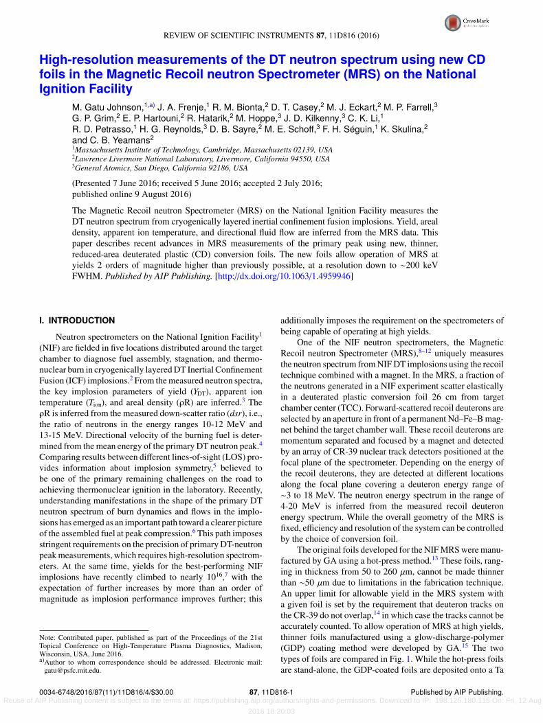
The original foils developed for the NIF MRS were manu-factured by GA using a hot-press method.13 These foils, rang-ing in thickness from 50 to 260 µm, cannot be made thinnerthan ∼50 µm due to limitations in the fabrication technique.An upper limit for allowable yield in the MRS system witha given foil is set by the requirement that deuteron tracks onthe CR-39 do not overlap,14 in which case the tracks cannot beaccurately counted. To allow operation of MRS at high yields,thinner foils manufactured using a glow-discharge-polymer(GDP) coating method were developed by GA.15 The twotypes of foils are compared in Fig. 1. While the hot-press foilsare stand-alone, the GDP-coated foils are deposited onto a Ta
0034-6748/2016/87(11)/11D816/4/$30.00 87, 11D816-1 Published by AIP Publishing. Reuse of AIP Publishing content is subject to the terms at: https://publishing.aip.org/authors/rights-and-permissions. Download to IP: 198.125.180.115 On: Fri, 12 Aug
2016 18:20:03
11D816-2 Gatu Johnson et al. Rev. Sci. Instrum. 87, 11D816 (2016)
FIG. 1. Comparison of (a) a 58 µm thick, 13 cm2 hot-press-made MRS foiland (b) a 35 µm thick, 4 cm2 glow-discharge-polymer (GDP) coated MRSfoil. The hot-press foil is a stand-alone plastic, while the GDP-coated foil isdeposited on a 13 cm2, 250 µm thick Ta backer. Both foils are mounted onthe same type of Ta-W alloy foil holder for fielding 26 cm from TCC. Notethat the thin hot-press coated foil shown in (a) requires clamping tabs aroundthe foil to prevent the plastic from curling when exposed on a NIF shot.
plate and can be made as small and thin as desired. Threesize/thickness combinations were selected to optimally covera wide range of yields. Performance parameters for standardhot-press and GDP-coated foils are summarized in Table I. Theallowable upper yield limit depends not only on total signalcount but also on etch conditions for the CR-39 detectors; ifthe material is etched longer, the tracks become larger, leadingto overlap at lower absolute signal levels. MRS CR-39 data areroutinely etched for 6 h at 80 ◦C in 6-normal NaOH. Theseetch conditions are assumed when determining the optimalyield range quoted in Table I. Longer etch time allows forimproved signal-to-background separation. The shortest etchtime demonstrated to work for MRS data is 2 h at the sameetch conditions; this etch time was assumed when deriving theupper yield limits quoted in Table I. In addition to allowingoperation at higher yields, the GDP-coated foils also providesubstantially improved resolution. The resolution of MRS isset by a combination of three factors: deuteron ranging in thefoil, geometry of the system, and ion-optical broadening fromtransport through the magnet.10 While some improvement inresolution between the hot-press and GDP-coated foils is dueto the reduced foil thickness, improved ion-optical propertiesdue to smaller foil area contribute as well.
II. PERFORMANCE OF NEW FOILS
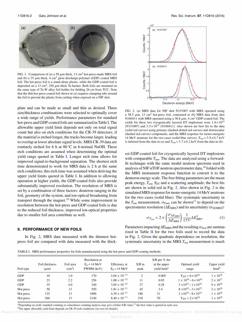
In Fig. 2, MRS data measured with the thinnest hot-press foil are compared with data measured with the thick-
FIG. 2. (a) MRS data for NIF shot N151007 with MRS operated usinga 58.5 µm, 13 cm2 hot-press foil, contrasted to (b) MRS data from shotN160411 with MRS operated using a 36.8 µm, 4 cm2 GDP-coated foil. Theyields for these two cryogenically layered DT implosions were 1.6×10¹⁵
(N151007) and 3.5×10¹⁵ (N160411). Also shown are best fits to the data(solid red curves) using primary (dashed-dotted red curves) and downscatter(dashed red curves) components, and the MRS response for mono-energetic14 MeV neutrons for the two cases (solid blue curves). Tion= 3.9±0.7 keVis inferred from the data in (a) and Tion= 3.7±0.2 keV from the data in (b).
est GDP-coated foil for cryogenically layered DT implosionswith comparable Tion. The data are analyzed using a forward-fit technique with the same model neutron spectrum used inanalysis of NIF nTOF neutron spectrometer data,16 folded withthe MRS instrument response function to convert it to thedeuteron energy scale. The free fitting parameters are the meanpeak energy, Tion, YDT and a scattering amplitude; the best fitsare shown in solid red in Fig. 2. Also shown in Fig. 2 is thesimulated MRS response for mono-energetic 14 MeV neutronsfor the two cases (solid blue). The systematic uncertainty inthe Tion measurement, σTion, can be shown17 to depend on thespectrometer resolution (∆EMRS) and its uncertainty (σ∆EMRS):
σTion = 2 ×(σ∆EMRS
∆EMRS
)1
1772∆E2MRS. (1)
Parameters impacting∆EMRS and the resultingσTion are summa-rized in Table II for the two foils used to record the datain Fig. 2. Given the quadratic dependence on resolution, thesystematic uncertainty in the MRS Tion measurement is much
TABLE I. MRS performance properties for foils manufactured using the hot-press and GDP-coating methods.
Foil typeFoil thickness
(µm)Foil area
(cm2)
Resolution atEn= 14 MeVFWHM (keV)
Efficiency atEn= 14 MeV
S/B inpeak
S/B per % dsrat the upperyield limita
Optimal yieldrange
Upper yieldlimitb
GDP 10 1.0 170 2.04 × 10⁻¹³ 2 0.005 YDT > 6×10¹⁶ 1 × 10¹⁸
GDP 23 2.2 256 1.08 × 10⁻¹² 11 0.05 1 × 10¹⁶−6×10¹⁶ 2 × 10¹⁷
GDP 35 4.0 340 3.05 × 10⁻¹² 27 0.28 3 ×10¹⁵−1×10¹⁶ 9 × 10¹⁶
Hot press 58 13 550 1.81 × 10⁻¹¹ 45 2.4 8 ×10¹⁴−3×10¹⁵ 2 × 10¹⁶
Hot press 135 13 1090 4.39 × 10⁻¹¹ 180 31 2 ×10¹⁴−8×10¹⁴ 1 × 10¹⁶
Hot press 260 13 2140 8.40 × 10⁻¹¹ 218 70 YDT < 2×10¹⁴ 1 × 10¹⁶
aDepending on yield, standard counting or coincidence counting analysis may give a better S/B value;11 the best value is quoted in each case.bThe upper allowable yield limit depends on CR-39 etch conditions (see text for details).
Reuse of AIP Publishing content is subject to the terms at: https://publishing.aip.org/authors/rights-and-permissions. Download to IP: 198.125.180.115 On: Fri, 12 Aug
2016 18:20:03
11D816-3 Gatu Johnson et al. Rev. Sci. Instrum. 87, 11D816 (2016)
TABLE II. Parameters impacting the MRS spectral resolution ∆EMRS and its uncertainty σ∆EMRS, and theresulting inferred systematic uncertainty in the Tion measurement (σTion). Where two values are given, the valuein italics is for the 36.8 µm, GDP-coated foil, while the value in regular print is for the 58.5 µm, hot-press foil.With ∆EMRS and σ∆EMRS known, σTion is calculated using (Eq. (1)).
MRS parameter Nominal value Parameter uncertainty Impact on σ∆EMRS (%)
Foil dist. to TCC (cm) 26 ±0.3 ±0.05/0.14Foil radius (cm) 1.15/2.02 ±0.01/0.024 ±0.04/0.15Foil thickness (µm) 36.8/58.5 ±0.3/2.0 ±0.81/3.3Aperture area (cm2) 20 ±0.2 ±0.02/0.03Magnet dist. (cm) 596 ±0.2 ±0.00d-density (1022 cm−3) 6.2/7.7 ±0.1 ±1.63/1.17Foil offset (cm) 0 ±0.1 ±0.68/0.54
σ∆EMRS/∆EMRS (%) 1.94/3.53∆EMRS (keV) 338/549σTion (keV) 0.142/0.679
reduced for the new, GDP-coated foils. Note that becausethe GDP-coated foils are transparent, their thickness can beabsolutely characterized using interferometry to an accuracyof ±0.3 µm, while the thickness of the hot-press foils can onlybe measured to an accuracy of ±2 µm.
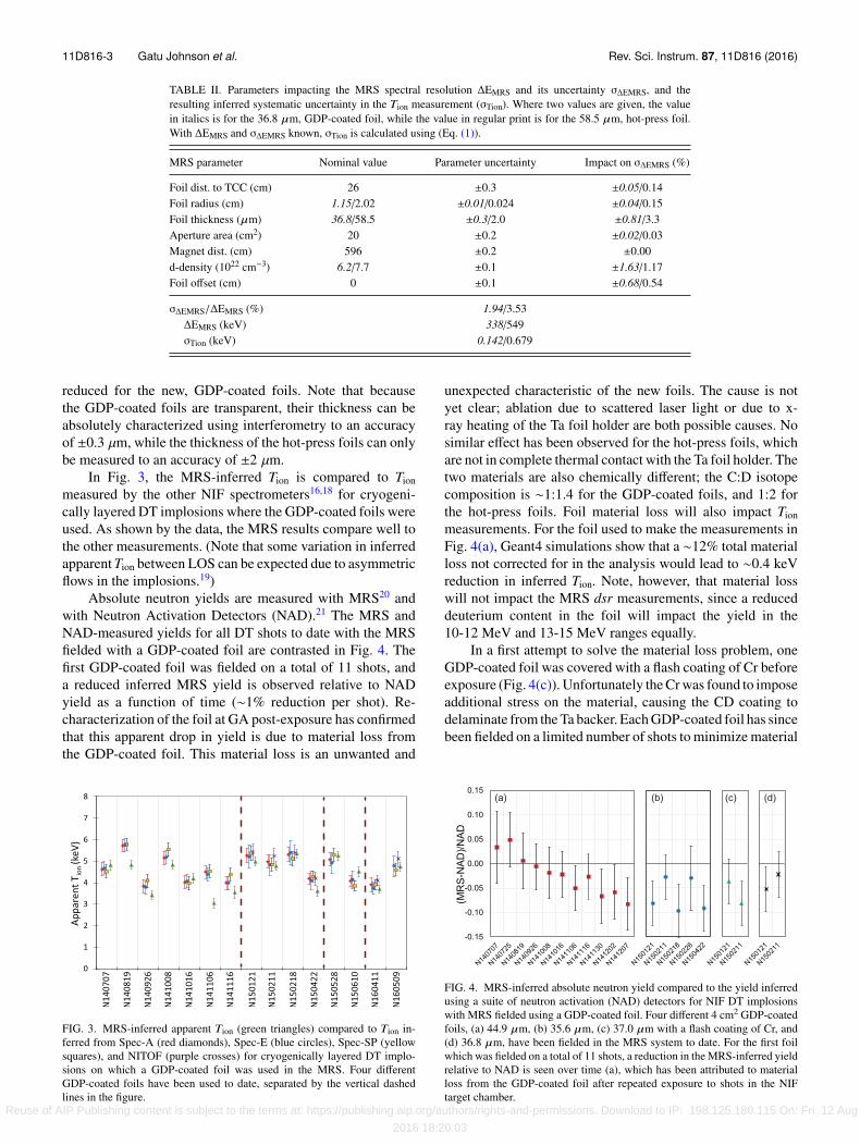
In Fig. 3, the MRS-inferred Tion is compared to Tionmeasured by the other NIF spectrometers16,18 for cryogeni-cally layered DT implosions where the GDP-coated foils wereused. As shown by the data, the MRS results compare well tothe other measurements. (Note that some variation in inferredapparent Tion between LOS can be expected due to asymmetricflows in the implosions.19)
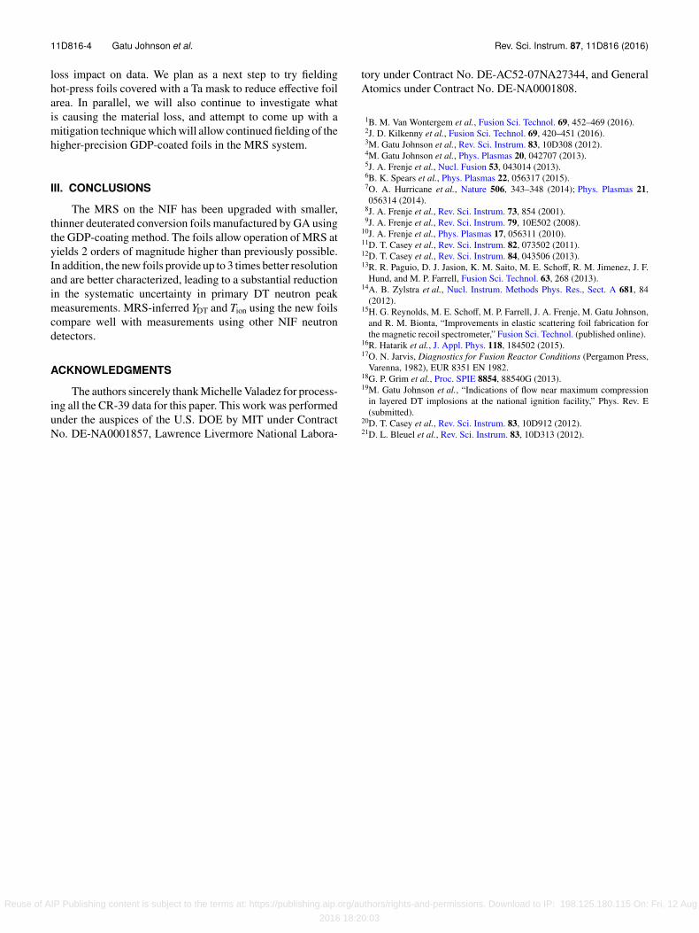
Absolute neutron yields are measured with MRS20 andwith Neutron Activation Detectors (NAD).21 The MRS andNAD-measured yields for all DT shots to date with the MRSfielded with a GDP-coated foil are contrasted in Fig. 4. Thefirst GDP-coated foil was fielded on a total of 11 shots, anda reduced inferred MRS yield is observed relative to NADyield as a function of time (∼1% reduction per shot). Re-characterization of the foil at GA post-exposure has confirmedthat this apparent drop in yield is due to material loss fromthe GDP-coated foil. This material loss is an unwanted and
FIG. 3. MRS-inferred apparent Tion (green triangles) compared to Tion in-ferred from Spec-A (red diamonds), Spec-E (blue circles), Spec-SP (yellowsquares), and NITOF (purple crosses) for cryogenically layered DT implo-sions on which a GDP-coated foil was used in the MRS. Four differentGDP-coated foils have been used to date, separated by the vertical dashedlines in the figure.
unexpected characteristic of the new foils. The cause is notyet clear; ablation due to scattered laser light or due to x-ray heating of the Ta foil holder are both possible causes. Nosimilar effect has been observed for the hot-press foils, whichare not in complete thermal contact with the Ta foil holder. Thetwo materials are also chemically different; the C:D isotopecomposition is ∼1:1.4 for the GDP-coated foils, and 1:2 forthe hot-press foils. Foil material loss will also impact Tionmeasurements. For the foil used to make the measurements inFig. 4(a), Geant4 simulations show that a ∼12% total materialloss not corrected for in the analysis would lead to ∼0.4 keVreduction in inferred Tion. Note, however, that material losswill not impact the MRS dsr measurements, since a reduceddeuterium content in the foil will impact the yield in the10-12 MeV and 13-15 MeV ranges equally.
In a first attempt to solve the material loss problem, oneGDP-coated foil was covered with a flash coating of Cr beforeexposure (Fig. 4(c)). Unfortunately the Cr was found to imposeadditional stress on the material, causing the CD coating todelaminate from the Ta backer. Each GDP-coated foil has sincebeen fielded on a limited number of shots to minimize material
FIG. 4. MRS-inferred absolute neutron yield compared to the yield inferredusing a suite of neutron activation (NAD) detectors for NIF DT implosionswith MRS fielded using a GDP-coated foil. Four different 4 cm2 GDP-coatedfoils, (a) 44.9 µm, (b) 35.6 µm, (c) 37.0 µm with a flash coating of Cr, and(d) 36.8 µm, have been fielded in the MRS system to date. For the first foilwhich was fielded on a total of 11 shots, a reduction in the MRS-inferred yieldrelative to NAD is seen over time (a), which has been attributed to materialloss from the GDP-coated foil after repeated exposure to shots in the NIFtarget chamber.
Reuse of AIP Publishing content is subject to the terms at: https://publishing.aip.org/authors/rights-and-permissions. Download to IP: 198.125.180.115 On: Fri, 12 Aug
2016 18:20:03
11D816-4 Gatu Johnson et al. Rev. Sci. Instrum. 87, 11D816 (2016)
loss impact on data. We plan as a next step to try fieldinghot-press foils covered with a Ta mask to reduce effective foilarea. In parallel, we will also continue to investigate whatis causing the material loss, and attempt to come up with amitigation technique which will allow continued fielding of thehigher-precision GDP-coated foils in the MRS system.
III. CONCLUSIONS
The MRS on the NIF has been upgraded with smaller,thinner deuterated conversion foils manufactured by GA usingthe GDP-coating method. The foils allow operation of MRS atyields 2 orders of magnitude higher than previously possible.In addition, the new foils provide up to 3 times better resolutionand are better characterized, leading to a substantial reductionin the systematic uncertainty in primary DT neutron peakmeasurements. MRS-inferred YDT and Tion using the new foilscompare well with measurements using other NIF neutrondetectors.
ACKNOWLEDGMENTS
The authors sincerely thank Michelle Valadez for process-ing all the CR-39 data for this paper. This work was performedunder the auspices of the U.S. DOE by MIT under ContractNo. DE-NA0001857, Lawrence Livermore National Labora-
tory under Contract No. DE-AC52-07NA27344, and GeneralAtomics under Contract No. DE-NA0001808.
1B. M. Van Wontergem et al., Fusion Sci. Technol. 69, 452–469 (2016).2J. D. Kilkenny et al., Fusion Sci. Technol. 69, 420–451 (2016).3M. Gatu Johnson et al., Rev. Sci. Instrum. 83, 10D308 (2012).4M. Gatu Johnson et al., Phys. Plasmas 20, 042707 (2013).5J. A. Frenje et al., Nucl. Fusion 53, 043014 (2013).6B. K. Spears et al., Phys. Plasmas 22, 056317 (2015).7O. A. Hurricane et al., Nature 506, 343–348 (2014); Phys. Plasmas 21,056314 (2014).
8J. A. Frenje et al., Rev. Sci. Instrum. 73, 854 (2001).9J. A. Frenje et al., Rev. Sci. Instrum. 79, 10E502 (2008).
10J. A. Frenje et al., Phys. Plasmas 17, 056311 (2010).11D. T. Casey et al., Rev. Sci. Instrum. 82, 073502 (2011).12D. T. Casey et al., Rev. Sci. Instrum. 84, 043506 (2013).13R. R. Paguio, D. J. Jasion, K. M. Saito, M. E. Schoff, R. M. Jimenez, J. F.
Hund, and M. P. Farrell, Fusion Sci. Technol. 63, 268 (2013).14A. B. Zylstra et al., Nucl. Instrum. Methods Phys. Res., Sect. A 681, 84
(2012).15H. G. Reynolds, M. E. Schoff, M. P. Farrell, J. A. Frenje, M. Gatu Johnson,
and R. M. Bionta, “Improvements in elastic scattering foil fabrication forthe magnetic recoil spectrometer,” Fusion Sci. Technol. (published online).
16R. Hatarik et al., J. Appl. Phys. 118, 184502 (2015).17O. N. Jarvis, Diagnostics for Fusion Reactor Conditions (Pergamon Press,
Varenna, 1982), EUR 8351 EN 1982.18G. P. Grim et al., Proc. SPIE 8854, 88540G (2013).19M. Gatu Johnson et al., “Indications of flow near maximum compression
in layered DT implosions at the national ignition facility,” Phys. Rev. E(submitted).
20D. T. Casey et al., Rev. Sci. Instrum. 83, 10D912 (2012).21D. L. Bleuel et al., Rev. Sci. Instrum. 83, 10D313 (2012).
Reuse of AIP Publishing content is subject to the terms at: https://publishing.aip.org/authors/rights-and-permissions. Download to IP: 198.125.180.115 On: Fri, 12 Aug
2016 18:20:03


![Calibration measurements for the efficiency and response ... · a fast neutron source which produces a continuous neutron spectrum such as a 252Cf spontaneous fission source [4]-[6]](https://img.pdfslide.net/doc/110x75/5e2d92b9b5abd06f313987ec/calibration-measurements-for-the-efficiency-and-response-a-fast-neutron-source.jpg)