Embed Size (px)
Citation preview
Policy | Procedure
Review date: 10 July 2020 Last amended date:
633 Issue date: 26 November 2008 1 of 29
High rise firefighting Official – Ops Security | Official – Health & Safety
New policy number: 633 Old instruction number: Issue date: 26 November 2008 Reviewed as current: 10 July 2017 Owner: Head of Operational Policy Responsible work team: Operational Tactics
Contents
1 Introduction .......................................................................................................................................................... 2
2 Hazards.................................................................................................................................................................. 2
3 Firefighting facilities and fixed installations .................................................................................................... 6
4 Planning ................................................................................................................................................................. 7
5 En route ................................................................................................................................................................. 8
6 On arrival ............................................................................................................................................................... 8
7 Operational procedure ....................................................................................................................................... 9
8 References ..........................................................................................................................................................18
Appendix 1 - 7(2)(d)...................................................................................................................................................19
Appendix 2 - Firefighting shafts ...............................................................................................................................20
Appendix 3 - Firefighting lifts ...................................................................................................................................21
Appendix 4 - Dry rising mains ..................................................................................................................................23
Appendix 5 - Wet rising mains .................................................................................................................................24
Appendix 6 - Water suppression systems..............................................................................................................25
Appendix 7 – Controlled dividing breeching – Protocols for use .....................................................................26
Appendix 8 - Key point summary – High rise firefighting ..................................................................................27
Document history .......................................................................................................................................................28

633 Issue date: 26 November 2008 2 of 29
1 Introduction
1.1 This policy is designed to provide guidance for operational personnel who are engaged in search, rescue and firefighting in high-rise buildings.
1.2 Further information is available from the documents set out in Section 8, within the station training support notes and presentations available via the training support icon on computer desktops.
1.3 A high rise building, for the purposes of this procedure, may be defined as a building containing floors at such a height or position that external fire fighting and rescue operations may not be feasible.
1.4 The term high rise building encompasses a wide variety of structures from conventional tower blocks containing residential flats to very large and complex commercial buildings. Some high rise buildings may be of multiple-use (e.g. occupied by a mixture of commercial and residential accommodation) and can contain complex systems which control the building’s internal environment, during normal use or during a fire situation.
2 Hazards
2.1 Fires in high rise buildings present a range of logistical and physical challenges to operational personnel which should not be underestimated.
2.2 Some of the hazards detailed below are specific to high rise buildings; others are more general in nature but are included due to their likely occurrence at high rise incidents and because the characteristics of the building are likely to intensify their effect.
2.3 Hazards of high rise firefighting can be grouped under three headings:
(a) Building height, layout and design.
(b) Fire behaviour and development.
(c) Firefighting and rescue operations.
Building height, layout and design
2.4 The height of the building, which may impact operations due to vertical travel distance affecting personnel, equipment and water supply.
2.5 Objects falling from height. These can be a risk to anyone entering or exiting the building. Debris can be ejected explosively and building materials such as glass and curtain walling can ‘plane’ some distance from the building.
2.6 Access for firefighters may be delayed due to security arrangements, such as code entry systems, security grilles and multi-lock door systems. Progress may be inhibited on more than a single occasion as devices are encountered at a number of points along the route to a fire.
2.7 Large or complex floor layouts, the operation of fire engineering systems (such as fire curtains) and a lack of information on the internal layout or flat or floor numbering systems can have an adverse impact on safe movement in the building. It may also increase the risk of teams becoming disorientated.
2.8 Individual maisonette style dwellings may be encountered where access can be up or down a staircase from the front door. Personnel may also encounter interlocking staircases within one enclosure that provide two separate paths of egress, to two or more floors and these are
633 Issue date: 26 November 2008 3 of 29
sometimes referred to as ‘scissor-style staircases’. If these are used to gain access to upper floors firefighters may find themselves exiting the stair at different locations on each floor level, or different floor levels. This can cause disorientation and/or affect the decision regarding where the bridgehead is sited. Some residential flats have emergency exits which may leave the flat on a different level to the initial access point.
2.9 Difficulty with lines of communication and radio reception. The scene of operations may be a considerable distance from the Brigade access level and point of command; additionally communication blind spots may exist within high rise buildings.
2.10 Risk of an intermediate floor or ceiling collapse in single dwellings which consist of more than one floor i.e. a maisonette style construction.
2.11 Firefighters falling from height due to the failure of external walls, panels or windows.
2.12 Risk of entanglement in electric cabling that has been displaced from surface-mounted cable trunking, fixings or failure of false ceilings.
2.13 High rise buildings may have a range of fixed installations and fire engineered solutions installed. If the building has been subject to poor standards of management and/or vandalism, these systems may be impaired, which increases risk to occupants, firefighters and other emergency service personnel in the event of a fire.
2.14 The operation of fire suppression/total flooding systems may result in either an oxygen deficient or irrespirable atmosphere.
2.15 Timber frame construction can result in rapid fire spread during the construction phase where fire protection measures may be absent. When under construction, timber framed buildings have a significant fire loading and consideration must be given to protecting surrounding risks. There is also a risk during occupation due to occupants damaging the internal framework of the structure allowing unseen fire and smoke spread.
2.16 When any high rise building is under construction or refurbishment additional hazards are likely to be present. Facilities such as firefighting shafts, rising mains and active/passive fire safety measures may be incomplete or absent. The introduction of modern materials and services (such as cable television) may compromise existing fire safety measures or compartments. This may cause the incident to develop in an unpredictable way following the unexpected spread of fire or smoke. Some buildings may be completed in phases and, in these cases there may be partial occupancy and people other than construction workers requiring rescue. Original doors may have been replaced with types which do not necessarily offer the required level of fire protection. This may promote more rapid fire spread or hinder access where additional security is encountered.
2.17 Radio waves from telecommunication antennas on high rise buildings generating electromagnetic radiation may cause adverse health effects linked to exposure to electromagnetic radiation.
Fire behaviour and development
2.18 Fire and smoke spread may occur in a upward, downward and/or horizontal directions. Fire spread from one compartment to another may be more rapid and less predictable than other building types due to the effects of wind. Fire spread can travel internally but more commonly occurs externally when fire breaks out of windows, this may lead to rapid spread to other compartments and floors.
2.19 Concealed smoke or heat travel: the products of combustion, including unburnt fire gases and unburnt domestic or commercial gas supplies, can also travel through or collect in areas where
633 Issue date: 26 November 2008 4 of 29
their presence is not obvious. Examples of this are compartments with high ceilings, in ducting, above false ceilings or other hidden roof voids. Basements are often joined to higher levels of a building through ventilation and utility ducting which can allow hidden travel of smoke and unburnt fire gasses vertically through the building.
2.20 Air currents can move up and down the face of a high rise building and this may lead to any smoke within the building being drawn downwards. Downward smoke spread, particularly in the staircase, can have a significant and adverse impact on operations.
2.21 Wind speeds are likely to increase with the height of the building and be affected by the position of any nearby buildings. A ‘blow torch’ type effect can be created by wind speeds forcing the products of the fire from the compartment, sometimes in unpredictable directions, resulting in rapid fire spread.
2.22 Burning material falling from upper floors can also spread fires by igniting combustible materials through open windows, on balconies and around the base of the building, compromising water supplies if hose is damaged.
2.23 Poor housekeeping and the storage of combustible materials in escape routes may obstruct the escape of residents and the progress of firefighting personnel, while assisting fire development. Combustible material in voids and cavities and poor quality construction can also contribute to the spread of fire.
2.24 Undivided stairways in high rise buildings have the potential to act as a chimney allowing the products of combustion to rise, increasing the risk of fire spread to other floors. Smoke rising through a high rise building may start to cool and will lose buoyancy, compromising escape routes. This is caused by the cooling smoke becoming less buoyant and falling within the stair enclosure. Older building guidance allows for a single staircase not to have a top level stair vent and therefore “mushrooming” can occur driving smoke and the products of combustion downwards.
2.25 In residential flats or maisonettes the opening of any door, window or emergency exit may create a chimney style effect leading to a rapid, unexpected increase in temperature.
2.26 Fires may be encountered on more than one floor as a result of the factors identified above or by acts of deliberate fire setting.
2.27 Some buildings will have compartments that have few or no openings. This can create a build up of toxic gases and reduce visibility. It may also create backdraught and fire gas ignition conditions and promote horizontal and vertical spread of fire and smoke. (See Policy number 793 - Compartment firefighting).
2.28 Uncontrolled ventilation and/or the operation of heating, ventilation and air conditioning systems can cause unpredictable fire and smoke spread.
Firefighting and rescue operations
2.29 Fire calls to a premises which is unknown, or has been subject to un-notified refurbishment or changes to use, may lead to insufficient resources being mobilised. This may cause delay in firefighting and search and rescue. Firefighters may have no or limited knowledge of the premises layout and any existing engineered solutions.
2.30 Where there is unexpected growth of fire or fixed installations are unavailable, commencing operations without sufficient resources or adequate access to fixed installations can increase the level of risk to occupants and firefighters (see also 2.42 below). There is also a risk that conditions
633 Issue date: 26 November 2008 5 of 29
in the fire compartment will worsen, if an intervention with sufficient resources is not made in a timely manner.
2.31 Firefighting operations can be affected by the type of evacuation being undertaken, the progress of the evacuation and the number and type of people being evacuated.
2.32 In a multiple-use high rise building there may be different evacuation or “Stay put” policies which may result in difficulty identifying whether persons are involved or need rescuing. Additionally occupants may not be aware of a building’s evacuation policy, leading them to behave differently to the IC’s expectations.
2.33 The need to assist with the evacuation of persons can divert teams away from the task they were briefed to undertake and this can have an adverse affect on the IC’s plan and resourcing for the incident.
2.34 Facilities such as fire mains, ventilation systems and compartmentation are provided to assist firefighters and to aid occupants evacuating the premises. Any unavailability of these facilities will increase risk to firefighters and may increase the resources required to resolve an incident.
2.35 The size and layout of some buildings may make it difficult to reliably determine the location, floor of origin and the extent of fire and smoke spread from the ground. This can create the potential for teams using firefighting lifts to proceed directly onto a floor area involved in fire or may mean that resources are deployed to inappropriate locations. The fire service access level may not be the recognised ground floor level of the building. This can lead to an incorrect count of floors to the fire floor potentially putting teams using the firefighting lift at risk.
2.36 There may be an insufficient water supply on upper floors due to either the height of the incident, vandalism, characteristics of the fire main or the limitations of fire service equipment.
2.37 The intensity of work rate in the fire compartment can lead to an increase in the core body temperature of firefighters. In addition, access to the fire may be limited to a single point so that teams entering the premises may have little or no option to avoid hostile conditions.
2.38 Hose, other equipment and firefighting operations in staircases and other parts of the building may create slip and trip hazards for firefighters and those evacuating the building. This risk will be intensified in buildings which have a single staircase.
2.39 The removal of casualties to medical care beyond the building may involve vertical transportation over a considerable distance. Personnel involved in carrying casualties long distances will be at increased risk of manual handling injury.
2.40 Verbal and physical attack, fire setting, vandalism and unlawful activities may compromise the safety of firefighters. Personnel may be the target of objects thrown or dropped from height. Traps, such as the positioning of sharp objects or flammable materials in bins or lift shafts, may be present.
2.41 Personnel may also encounter unexpected hazards associated with activities such as drug manufacture and storage; this type of activity is also associated with increased risks from electrical hazards due to illegal access to power supplies. Additional hazards may include the deliberate placement of flammable materials or gas cylinders in properties and/or additional fire setting while teams are in attendance.
2.42 At incidents where hoarding of property is encountered (see Policy number 829 - Hoarding), a number of hazards may be present. These include;
(a) Large volumes of combustible materials,
(b) Difficult access/egress and changes to the normal layout of a premises,
633 Issue date: 26 November 2008 6 of 29
(c) Items of property falling and trapping occupiers/firefighters,
(d) Absorption of water which will add significant weight, increasing the likelihood of collapse,
(e) Deep seated/hidden fires,
(f) Contaminated water run-off.
2.43 Firefighting operations may breach firefighting lobbies increasing risk to occupants and impacting on personnel at the bridgehead. The size of firefighting lobbies may be insufficient to contain the resources necessary to mount an effective attack. It will be necessary to run hose lines onto protected routes and stairways to undertake firefighting and this will allow smoke to spread into previously unaffected areas of the building.
2.44 Total or partial electrical failure can occur as a result of damage by fire, heat or water used for firefighting operations, sprinkler run off and any failure of water supply pipes. Where electricity supplies have been tampered with the supply may not trip and increase the risk of electrocution.
2.45 Any failure of firefighting lift equipment or use of non-designated lifts can lead to firefighters and evacuees becoming trapped in a lift car. Either the lift, its shaft and/or machine room may be affected by the spread of smoke, fire, heat and water ingress from firefighting operations. Any diversion of resources necessary to rescue trapped lift occupants will have an adverse impact on firefighting operations.
2.46 There are public expectations that firefighters will attend incidents and that personnel will put themselves at risk to save lives. This can lead to moral pressure to act immediately, even if the incident is beyond the capacity of resources available at the time. This is most likely to be the case if an IC identifies the potential for saveable life is not proportionate to the risks to personnel and either decides not to commit or to withdraw personnel.
3 Firefighting facilities and fixed installations
3.1 Facilities are provided within high rise buildings to assist in a safe and timely intervention by the fire service.
3.2 Building Regulations require all buildings over 18m in height to make provisions for firefighting and firefighter access. Those in excess of 60m require wet systems (as of 2006 – 50m). The basic facilities provided within these buildings may include:
• Firefighting shaft. • Dry/wet rising mains (DRM or WRM). • Firefighting lift.
3.3 Firefighting shafts including fire mains (but not firefighting lifts) may also be found in certain building types with floor heights exceeding 7.5m. In addition to those within firefighting shafts, fire mains may also be located in other staircases and/or corridors within a high rise building.
3.4 Sprinklers and other fire engineered systems may also be found in high rise buildings. The installation of sprinkler systems may indicate that there are larger compartment areas with significant fire loadings present.
3.5 It is important to understand any engineered system installed and how it operates during familiarisation visits. Additional information on firefighting facilities and fixed installations is provided in Appendices 2 – 6.
633 Issue date: 26 November 2008 7 of 29
4 Planning
4.1 Operational intelligence should be gathered and recorded in accordance with Policy number 800 - Management of operational risk information.
4.2 Station personnel should assess the hazards identified for a premises or location and determine the level of risk by reference to factors such as size, complexity and layout. The contents, any processes carried out and occupancy should also be considered and the premises must be included within the Operational Risk Database (ORD) as the Premises Risk Assessment score dictates.
4.3 Simple line drawings identifying individual compartments(or flat numbers)associated with floor levels will assist prioritising rescue operations. This is of particular importance where multiple compartments over many levels may be affected by fire or smoke. Some residential flats have emergency exits which should be recorded.
4.4 Planning must consider the appropriate Pre-Determined Attendance (PDA). This can be temporarily or permanently increased to compensate for factors such as the absence of fixed installations and the type of incident likely to be encountered. For further information, see Policy number 412 - Mobilising Policy.
4.5 To increase the PDA for a high rise premises to cover a temporary or permanent absence of fixed installations, submit a request via the special attendance database at: hotwire > station diary > special attendance request. Out of office hours, requests can be made via the officer of the day (OOD).
4.6 Planning must consider the knowledge and understanding of fixed installations and how they can assist fire and rescue operations. Where required, advice and guidance should be obtained from Fire Safety Officers (FSO)regarding fixed installations provided, such as sprinklers, ventilation systems (including manual over-rides) and rising mains. FSOs can be invited to familiarisation visits.
4.7 Some older premises may not provide all the expected firefighting facilities, in which case additional planning may be required.
4.8 The tactics and resources required to mount safe rescue and fire fighting operations should be assessed, practiced and confirmed where necessary for the building concerned. This may include the following considerations:
(a) Planning for fire spread beyond the compartment of origin and the potential for multiple rescues.
(b) Consideration of the logistical and physical demands on personnel conducting search and rescue over multiple floors and compartments.
(c) Contingency plans for loss of water or inadequate water supplies (including internal supplies and identification of distances from the bridgehead to the full extent of the possible fire compartment).
(d) The time required to assemble sufficient resources from the PDA.
(e) Ensuring adequate resources are provided to undertake initial assessment, effect an early response and establish an effective safe system of work.
(f) The complexity and size of building design and security measures, such as code entry systems, which may delay teams reaching the scene of the fire.
(g) Staircases and lifts not accessing all floors.
633 Issue date: 26 November 2008 8 of 29
(h) The siting of bridgeheads and alternative options if they are compromised by worsening conditions.
(i) Floor numbering, as some buildings may have concealed entrances and the gradient of the ground may lead to front and rear elevations having different floor counts.
(j) Alternative communication arrangements to overcome any radio blind spots.
(k) Training to implement operational procedure, site specific plan and to overcome worst case scenarios, such as teams shut in a firefighting lift and unavailability of fixed installations.
(l) Familiarisation and regular testing of the Fire Initial Response Equipment (FIRE) bag to ensure adequate resources and competencies are in place for a rapid response.
4.9 Borough training plans should take account of the quantity and nature of high rise premises and ensure this is reflected appropriately in the exercise schedule. Training should include scenarios designed to develop and test operational tactics for overcoming the failure of fixed installations and use of the Fire Initial Response Equipment.
4.10 Where LFB Premises Information Boxes, are available, the information provided should be checked for accuracy and completeness during 7(2)(d) visits. Premises evacuation procedures and their impact on firefighting tactics should be considered as part of 7(2)(d) visits (see Policy number 513 - Premises information box systems).
4.11 Where anti social behaviour towards firefighters has been identified consider an appropriate intervention strategy as part of community fire safety.
4.12 Further guidance on the type of information which should be gathered during 7(2)(d) visits to high rise premises is contained in Appendix 1.
4.13 Where radio antennas are fitted to high rise buildings, these should be identified and recorded during 7(2)(d) visits.
5 En route
5.1 Information received en route and any planning that may affect on arrival tactics must be passed to all personnel.
5.2 Full use must be made of all operational information systems, such as Mobile Data Terminals (MDT). Where floor plans or virtual high rise information plates are available these should be printed off.
6 On arrival
6.1 Attendance should be made to the main entrance of the premises, unless an agreed RVP or split attendance has been identified during the planning phase or prevailing conditions dictate otherwise.
6.2 The siting of appliances that form the PDA should take into account the potential need for access for aerials, other specialist appliances and emergency services, and the potential danger of objects falling from height.
6.3 To establish effective command and control, the IC should:
(a) Remain at ground floor level unless planning arrangements have identified a more appropriate location e.g. the Fire Control Centre.
633 Issue date: 26 November 2008 9 of 29
(b) Gather all available relevant information from sources such as building occupants, from any building or evacuation plan and from any premises information plate. The IC should confirm the accuracy of any information received by cross-checking different sources and clearly conveying what information they require.
(c) Identify which floor(s) the incident is located on in order to determine where the bridgehead should be sited.
(d) Carry out a 360o visual inspection to identify affected areas and fire spread.
(e) Ensure initial teams equip themselves with all of the necessary equipment to set up a bridgehead before going aloft (see 7.24).
(f) Establish the location and status of any fire control, fire engineering and/or fixed installation systems.
(g) Secure water supplies for firefighting teams at the bridgehead. The hydrant supply and deliveries from the pump to the DRM must be twinned and charged using 70mm hose.
(h) Establish a cordon to help protect personnel and others from falling materials.
(i) Determine the status of any Heating, Ventilating and Air Conditioning (HVAC) systems in the building.
(j) Implement reliable lines of communication with the bridgehead, pump operator and other sectors.
6.4 The IC should also give early consideration to the following points:
(a) Whether additional resources are required to support operations.
(b) Recognise the effect of wind, noting this may be amplified and made more unpredictable by factors such as the building’s height and its proximity to other tall buildings.
(c) The need to layout jets to control fires caused by falling debris and deploy ground monitors to prevent external fire spread.
(d) The need to establish, if appropriate, separate attack and evacuation stairwells. If this tactic is employed, personnel assigned to assist evacuation must then use a different stairwell that should be clearly identified as the evacuation stairwell.
7 Operational procedure
Securing water supplies for firefighting
7.1 DRMs and WRMs have a finite capacity to deliver water. If multiple jets are in use, it may not be possible to achieve optimum flow rates or recommended operating pressure for individual branches. Branch flow control facilities can be used to improve distribution between all jets in use.
7.2 A DRM can deliver at least 1500 litres of water per minute. If the requirement for water exceeds the DRM capacity, the IC should consider augmenting supplies, such as by hauling hose aloft; use of aerial appliances; and/or by laying hose lines up staircases. When laid on stairways, hose should be positioned in such a way that it minimises obstruction. Vertical water relays may be required, using intermediate pumps to increase flow. Wet rising mains are designed to supply 1500 litres per minute for 45 minutes as a minimum.

633 Issue date: 26 November 2008 10 of 29
7.3 The IC must consider the building’s construction, size, layout and fire load when making decisions regarding the size of hose lines and weight of attack to be used at an incident.
7.4 At larger incidents, the IC will need to consider the optimum means to provide the overall quantity of water required, noting that this could include augmentation of fixed installations and the supply of internal and external jets and monitors.
7.5 MDTs will provide the location of hydrants, the size of the water main supplying them and the location of emergency water supplies. Bulk media advisors (BMA) are available to provide advice with regard to securing and optimising water supply.
7.6 If fixed installations are vandalised or unavailable for any other reason, the IC should consider implementing alternative tactics and/or requesting additional resources. The F.I.R.E tool roll contains a riser outlet wheel, adjustable spanner, mole grips and rubber hose washer which may assist in the use of outlets in disrepair.
7.7 If the nature of the debris poses a risk to hose lines going into the building, consideration should be given to either protecting these with hose ramps or finding an alternative route outside of the area within which the debris is falling.
7.8 Effective communication between BA teams, bridgehead, the IC and the pump operator are necessary to ensure best use is made of the available water supply.
7.9 WRM installations may require augmentation at larger or protracted incidents. (See appendices 2, 4 and 5 for further information regarding dry and wet rising mains).
7.10 Some high rise buildings have fire sprinkler systems and, where fitted, a firefighter must be sent to the main stop valve. This is usually located on the ground floor, but it may be located elsewhere, depending on building design. The sprinkler system should only be switched off on instructions from the IC, following consideration of the points outlined in Appendix 6.
7.11 When in operation, the sprinkler system should not normally be turned off.
Securing and using the firefighting lift
7.12 Where the height and location of the incident makes the use of a fire lift beneficial, the firefighting lift should be identified and a firefighter detailed to take control of, and remain in the lift. The IC should also be aware that some lifts may not access all floors of the building.
7.13 Only designated firefighting lifts are safe to use during an operational incident and therefore other lifts must not be used for firefighting operations. The IC should be aware that some older style lifts may not have the same capabilities as modern lifts.
7.14 Teams must exit the fire lift at least two floors below the floor where the fire is reported or believed to be. This is to ensure that the risk of firefighters becoming involved in the fire is minimised.
7.15 If the location of the fire is not known with a reasonable level of certainty, personnel should approach the believed or likely location of the incident with caution, using a protected staircase.
7.16 The firefighting lift should remain at the established bridgehead so that rescued persons can be quickly brought to ground floor level.
7.17 In the event that the fire lift is not available, consideration should be given to:
(a) The resource implications for teams accessing and carrying equipment to the bridgehead.
(b) The use of aerial appliances to transport equipment to the bridgehead (if the building design makes this a viable option).

633 Issue date: 26 November 2008 11 of 29
(c) Additional resources to enable safe manual handling of casualties down stairways to the point where they can be passed to the care of the Ambulance Service.
7.18 See Appendix 3 for further information regarding firefighting lifts.
Establishing a bridgehead and fire sector
7.19 The bridgehead should be located two floors below the fire floor unless planning arrangements or the specific design features of the building allows for safe air to be reliably maintained in a position which is closer to the fire. The bridgehead should be established in a firefighting lobby and not in a corridor (unless the building design results in the corridor performing the lobby function).
7.20 When positioning a bridgehead, consideration should be given to smoke spread through doors that will be opened and which will have to remain open for firefighting purposes.
7.21 A minimum of Crew Manager must be nominated as the fire sector commander. The fire sector commander will be responsible for establishing a bridgehead and committing teams to firefight and search and rescue as required.
7.22 The IC should give early consideration, in relation to the size of the incident and scope of responsibility, to whether it is necessary to nominate a more senior manager to take over the fire sector commander role.
7.23 Sectorisation of high rise incidents should be in accordance with Policy number 434 - Sectorisation at incidents. Due to potential congestion at larger incidents a staging area below the bridgehead may be required for additional resources.
7.24 As the water supply is being secured, the fire sector commander will take a minimum of three firefighters to the bridgehead. They will be a firefighting/rescue team of two BA wearers and a BA entry control officer (ECO).
7.25 The following equipment must be provided at the bridgehead as soon as possible:
• Two lengths of 45mm hose with carrying straps • Immediate Emergency Care (IEC) pack • Two BA sets • Long Line • Breaking in Gear • One BA Board • Thermal Imaging Camera) • One F.I.R.E bag containing:
− One controlled dividing breeching − Three Hose Identifying Sleeve − One DeltaFire Quickattack branch − One Set of lift access keys − One F.I.R.E tool roll (see Appendix 7)
7.26 As soon as practicably possible, the F.I.R.E system must be augmented with:
• Sufficient hose for two lines to reach the affected area of the building • An additional branch • Bracket and tripod for BA board • Access keys/codes • Floor plans (if available) • Forward information board (FIB)
633 Issue date: 26 November 2008 12 of 29
7.27 The above equipment is a minimum, and other equipment such as an appropriate extinguisher can also be provided, if resources permit and the nature of the incident indicates this is appropriate.
7.28 The F.I.R.E system contains all of the equipment which must be in place as a minimum requirement for High Rise Firefighting. However, the 45mm hose wrapped in carrying straps may also be required for other types of firefighting. Therefore only two of an appliance’s four 45mm jet capacity must be wrapped in these straps. The straps are provided because the F.I.R.E bag is not designed to carry hose. Crews must be aware of Policy number 540 - Manual handling operations procedure, when carrying equipment to the bridgehead. The bag must be fully closed when carried, without protruding equipment.
7.29 Regular communication should be maintained to ensure that the IC is aware of the developing situation and can anticipate resource requirements effectively. This also ensures the fire sector commander is kept updated regarding any fire and smoke spread that may only be visible to those outside the building.
7.30 Information available either on site or available on appliances should be used to identify floor numbers, flat and compartment numbers (or other identification) and their proximity to the fire compartment. This can include signage, building plans or plans drawn from the floor layout of unaffected floors where the floor layout is consistent throughout the building.
7.31 Where specific information on the location of persons requiring rescue is available this should be confirmed with teams and recorded on FIBs. A record of persons rescued and areas searched or partly searched should be made to inform additional teams. This will assist with prioritising further rescues and reduce repeated searches of the same areas. Plans of the building will assist this process.
7.32 Where there is information that hoarding of property may be present teams should be made aware and consideration given to requesting additional resources. Large volumes of combustible materials will require a significant weight of attack and incidents are often protracted during the damping down and turning over phase. Any rescue efforts will be extremely demanding and damage control will be difficult.
7.33 Consideration should be given to the effect that fire service operations and vertical/downward fire spread may have on an established bridgehead. If worsening conditions or fire spread at or below the bridgehead require it to be repositioned, the following should be acted upon:
(a) The IC, all officers and BA teams must be informed of any decision to re-locate the bridgehead.
(b) All BA teams must be informed to ensure they monitor their air supply and take the new distance into account when assessing their turn around time.
(c) As relocation will increase the travel distance for BA teams, consideration must be given to the immediate withdrawal of BA teams. Any decision to withdraw breathing apparatus teams must be balanced against the urgency of the task(s) they are performing.
(d) If not already established, an emergency team the same size as the largest committed team and rigged to at least the same level of protection must be made available at the bridgehead as soon as practicable.
(e) All information and resources should be transferred to the new bridgehead location.
(f) Consider implementing Stage 2 BA procedures.

633 Issue date: 26 November 2008 13 of 29
(g) Where life saving operations are delayed, the IC should consider alternative methods of effecting rescue.
Messages
7.34 When attending a high rise incident, the IC will have to gather sufficient information to carry out a risk assessment and implement the appropriate safe systems of work. The implementation of high rise procedure should be reflected in an informative message to Brigade Control as soon as possible. If sent in isolation, the full details of the incident (e.g. dimensions, area involved) do not need to be sent. See Policy number 518 – Messages from incidents. Example: “From …………… at …………; high-rise procedure implemented, tactical mode Oscar”
7.35 The above message indicates that a risk assessment has been carried out, and that a safe system of work has been implemented. This message can only be sent where the following minimum systems of work have been implemented;
(a) the location of the bridgehead has been risk assessed as appropriate for the incident,
(b) access and egress to and from the bridgehead is secured and maintained,
(c) the bridgehead is established with two charged jets deployed (as described in 7.35 and 7.36 below).
Committing teams
7.36 All specific tasking of teams should take place at the bridgehead once the decision has been made by the IC to commit them to internal firefighting and rescue operations above the bridgehead.
7.37 Any delay committing teams can increase the likelihood of fire growth and fire spread occurring and in turn, can increase the pressure on firefighters to act before sufficient resources are available. The IC should give early consideration to whether additional resources are required to assist in the evacuation of occupants or to replace teams that have been diverted to this task.
7.38 The fire sector commander should inform the IC before committing any BA teams. The initial BA team’s charged branch should (where possible) be supplied from the rising main outlet one floor below the fire; if this unavailable, the nearest available outlet below that should be used. Refer to Appendix 7 Controlled Dividing Breeching – Protocols for use for further guidance.
7.39 An additional BA team with a second jet should be provided as soon as possible, in order to protect and support personnel involved in rescue/firefighting operations. This second jet should be at least one hose length longer than the first. This allows the first team to be supported in firefighting and allows rescue of the team without compromising water supply. The second jet can be supplied from the rising main outlet on the fire floor or the next available outlet below the fire floor, as appropriate (this can include the additional outlet provided by the dividing breeching).
7.40 If signs, symptoms or conditions that may lead to backdraught, flashover or other abnormal fire development are present, a covering jet and BA team must be present before the search and rescue/firefighting team are committed into the fire compartment. Any entry into a fire compartment should be in accordance with Policy number 793 – Compartment firefighting.
7.41 Hose lines should be laid and charged in an area unaffected by fire or smoke and behind the safety afforded by a fire resistant structure or fire resisting door(s). Hose lines should be fully charged before entering any doorway to prevent them passing under a door, which could
633 Issue date: 26 November 2008 14 of 29
subsequently cause a flow restriction or obstruction into or out of the premises when the jet is charged.
7.42 In circumstances where personnel need to work in an area above the bridgehead which is not affected by fire or smoke and the IC has confirmed that the building’s construction and any fire engineered solutions have not been compromised, teams can be committed without BA. These teams must maintain communication with the bridgehead and a Safety Officer must be deployed in the stairwell and be in contact with other Safety Officers and the IC outside the building. Teams should be withdrawn as soon as it is believed there is a risk that fire or smoke is likely to spread to the unaffected area.
7.43 The IC should consider team welfare and rotation of firefighters, in light of the effort required to move personnel and equipment to the Bridgehead.
7.44 The implementation of hydration regimes will help to minimise physiological stress (see Policy number 284 - Metabolic heat stress).
Search and Rescue
7.45 Search and rescue within high rise buildings presents logistical and physical challenges to operational personnel which should not be underestimated. They will generally be resource intensive and therefore any additional resources required should be requested early in the incident. The travel time from the bridgehead to the scene of operations should be considered.
7.46 It is good practice to nominate a search co-ordinator early in an incident to support a systematic and thorough process. See Policy number 803 – Search and rescue procedures within structures.
7.47 Accurate records should be maintained to confirm areas that have been searched as well as identifying areas which still require searching. FIBs can be used to record this information and ensure its availability should the bridgehead be relocated.
7.48 Door marker tags and door marker crayons, which are available in the FIRE bag tool roll, should be used to designate rooms or flats that have been cleared by crews and assist in a comprehensive search plan.
Evacuation
7.49 The IC should consider following the evacuation plan devised as part of the occupier’s fire risk assessment, unless the fire situation dictates otherwise.
7.50 It may be necessary to undertake a partial or full evacuation in a residential building where a “Stay put” policy is normally in place.
7.51 Firefighting operations can be adversely affected by the type of evacuation being undertaken, the progress of the evacuation and the number and type of people being evacuated. Evacuation can be made more resource intensive if the occupants have an impaired ability to make their own way to safety; for example, disabled persons or those under the affect of alcohol or drugs may need greater assistance. The IC should consider:
(a) the effect of firefighting tactics on evacuation (and vice versa),
(b) the resources required to support the evacuation or “Stay put” policy,
(c) where it is safe to do so, using other emergency service personnel to assist with evacuation; and that widespread evacuation may divert teams from the task(s) they were briefed to undertake which may require additional resources,
(d) the need to establish, if appropriate, separate attack and evacuation stairwells.

633 Issue date: 26 November 2008 15 of 29
Fire Survival Guidance
7.52 Incidents in high rise buildings can lead to fire survival guidance (FSG) calls being received by Brigade Control. In these circumstances, the IC should take action necessary to either rescue or reassure occupants.
7.53 The management of FSGs is resource intensive. Where FSGs are received at a high rise incident Control will mobilise a stand alone FSG attendance. This attendance is additional to any other resources that have been requested or are en-route. If the size of the incident is subsequently increased, the mobilising system will not include these resources when calculating the additional attendance required.
7.54 A clear record of FSG calls and relevant information on their location and circumstances will be necessary at the mobilising centre and the incident ground. This will assist confirmation of priorities and subsequent reassessment of those priorities should information change as the incident develops.
7.55 The advice offered during fire survival calls should be re-evaluated throughout an incident and this may require a change in the advice given. In exceptional circumstances an IC may consider informing control that their advice to FSG callers should be altered e.g. to attempt to leave their property. The IC should remember that this advice may be contrary to National Policy for control staff on FSGs and liaison with the officer in charge at control will be required for agreement to change the prescriptive advice. See Policy number 790 - Fire survival guidance calls.
Ventilation 7.56 Ventilation should only be undertaken on the instruction of the IC. Before operating any
ventilation systems or undertaking ventilation, the IC should consider:
(a) any adverse affect on fire development, such as the risk of causing a backdraught or flashover and the effects on personnel and occupants in the hazard zone.
(b) what impact wind may have if doors, windows or emergency exits are opened or should fail prematurely.
(c) the need to communicate with and possibly withdraw personnel in affected areas or occupants still in the building.
(d) that sufficient resources are in place to contain the fire if there is a need to breach any built-in or engineered safety systems.
(e) that measures such as covering jets are in place to protect surrounding risks.
7.57 If the risk cannot be properly assessed or sufficient control measures implemented, ventilation should only be undertaken in the post fire stage. The IC must maintain an awareness and understanding of the effect and impact of any ventilation tactics employed throughout an incident.
7.58 All lobby doors should normally be kept closed except when it is necessary for them to be opened to facilitate the movement of personnel and equipment through the building. Some ventilation shaft systems require inlet air from doors being held in the open position. This is noted by doors opening inwards rather than outwards.
7.59 Any building ventilation systems operating on arrival should be left switched on until the IC is satisfied, as a result of discussion with an on-site engineer or FSO, that switching off the system will not cause an escalation of the incident. Measures such as covering jets should be considered to protect surrounding risks.

633 Issue date: 26 November 2008 16 of 29
7.60 ICs should consider, on the basis of expert advice and building design, using any available ventilation systems to minimise smoke-logging in areas outside the fire sector.
7.61 Before operating any heating or ventilation systems or undertaking ventilation the IC should also identify:
(a) the path that fire, heat and smoke will follow to escape to open air or another compartment within the building,
(b) any adverse affect on fire development, such as the risk of causing a backdraught or flashover,
(c) any adverse affect on evacuation in progress, and
(d) what impact wind may have if windows or doors are opened or should fail prematurely.
7.62 Door stoppers, contained within the FIRE bag tool roll, can be used to wedge security doors below the bridgehead and should only be used above the bridgehead on the approval of the IC having taken ventilation into consideration.
Building design and fire safety measures
7.63 During a fire, the level of risk can be significantly increased if any of the building’s design measures are compromised. This can include the loss of compartmentation, ventilation or sprinkler systems.
7.64 The IC should determine what fixed installations are available, check whether they are functioning and incorporate them as appropriate within the operational plan.
7.65 If any fire safety measures have been compromised, the IC should consider requesting additional resources if these would be needed to implement alternative tactics.
7.66 The IC should consider the impact of building materials and contents on fire spread; for example, PVC window frames may be subject to early failure. The failure of any external window frames or walls will create an increased risk of firefighters falling from height and, where this occurs, the IC should ensure appropriate procedures are in place to maintain a safe working area. See Policy number 547 - Line operations.
7.67 Automatic fire curtain systems may be present in a variety of configurations and orientations. If the building has an automatic fire curtain system installed, the IC must ensure teams are suitably briefed on their location(s) and the risk they can pose to safe egress from the building, should they operate whilst a team is committed in the compartment where they are installed.
7.68 A FSO will be informed of all four pump fires, will attend all five pump fires and above and can be requested whenever specialist advice is required by the IC.
7.69 Where firefighters will be working within the vicinity of radio antennas, ICs should follow guidance within Policy number 298 - Operations at radio transmitter sites.
Safety officers
7.70 The early appointment of one or more Safety Officer(s) will help ensure that risks are either eliminated or reduced to an acceptable level.
7.71 The IC should appoint Safety Officers as soon as practicable to monitor conditions in the staircase or shaft being used for the bridgehead and observe all relevant external sides of the building. Identified hazards within and external to the building should be established to inform
633 Issue date: 26 November 2008 17 of 29
the IC’s plan for removing, reducing or controlling the associated risks in the associated sectors. The Safety Officer working outside the building should check for;
(a) falling debris,
(b) cordon maintenance for personnel, other emergency services and the public, and
(c) external spread of fire and smoke.
Safety cordon
7.72 ICs must consider the implementation of an appropriate sized hazard zone. This should take into account the size, height and construction of the building, as this will affect the footprint in which debris and other items may fall.
7.73 The hazard zone should separate those at risk from the hazards, facilitate operational activities and protect the scene from unauthorised access to evidence or property. The IC should undertake early liaison with the police, who may be best placed to resource and manage cordons around a high rise incident.
Damage control
7.74 The IC should give early consideration to damage control and, due to the fact high rise premises frequently have high levels of occupancy, any additional resources needed to mitigate damage from fire and the effects of firefighting operations.
7.75 It should be remembered that fire, smoke and the water used for firefighting may be able to travel considerable distances through shafts and voids that may form part of the building construction.
Anti-social behaviour
7.76 If Brigade personnel are subject to either verbal or physical threat or abuse, the IC should request the attendance of the police.
Communication difficulties
7.77 Where appropriate and available the IC should consider the use of alternative radio channels to manage the volume of radio traffic or, where there are communication difficulties, other equipment, such as radio repeaters, leaky feeders and hand-held digital main scheme radios (see Policy number 488 - Incident communications). Door entry call points, internal telephones, public address systems or loudhailers can be employed to communicate with building occupants. Consider the use of runners.
7.78 When radio communications with any team committed to the incident are lost, it must not automatically be assumed that any loss of communications is associated with transmission difficulties caused by the building. Every effort should be made to re-establish communications as quickly as possible.
7.79 If a BA team loses radio contact with the communications operator/ECO, the team leader will decide whether to withdraw. If both telemetry and radio signal is lost the BA team must withdraw. If communications or contact is lost with any BA team without warning a BA team will be committed to investigate. If it is established that the original BA team is in difficulty, the IC must be immediately informed.

633 Issue date: 26 November 2008 18 of 29
Post incident
7.80 As appropriate to the nature and scale of the incident, the following measures should be considered to help eliminate or remove risks after an incident:
(a) fire protection and structural safety should be assessed to ensure that it has not been compromised before handing over the building to a responsible person,
(b) arrangements should be made with the occupiers to reinstate, as far as practicable, all fixed installations, such as ventilation systems and fire alarms, to their normal working condition,
(c) consider the need to review existing information held on a premises or location, or the need to add a new premises or location into future planning,
(d) where the scale and nature of the incident makes it justified, arrangements should be made for personnel to make a contemporaneous written record of their actions, (see Policy number 828 – Recording decisions at incidents. This information may be used to assist in any internal or external investigations or enquiries that follow any incident, such as a Coroner’s Court or public enquiry,
(e) any fire safety contraventions identified at an incident should be followed up by the relevant Fire Safety team and/or reported to the appropriate authority.
(f) consideration should also be given to any community safety interventions which may be appropriate, such as promoting smoke alarm ownership or highlighting issues such as vandalism or anti-social behaviour to relevant partner agencies.
(g) further advice and guidance can be obtained from FSOs.
8 References
8.1 The following policies are relevant to and should be read in conjunction with this policy:
• Policy number 47 – Sprinklers and drenchers • Policy number 120 – Phased evacuation of office buildings • Policy number 284 – Metabolic heat stress • Policy number 238 – Incident command procedures • Policy number 412 – Mobilising policy • Policy number 434 – Sectorisation at incidents • Policy number 466 – Respiratory protective equipment - breathing apparatus – operational
procedures • Policy number 513 – Premises information box systems • Policy number 518 – Messages from incidents • Policy number 540 - Manual handling operations procedure • Policy number 543 - Immediate emergency care (IEC)/medical first aid • Policy number 547 – Line operations • Policy number 790 - Fire survival guidance calls • Policy number 793 - Compartment firefighting • Policy number 794 – Lifts and incidents involving lifts • Policy number 800 – Management of operational risk information • Policy number 803 - Search and rescue procedures within structures • Policy number 828 – Recording decisions at incidents • Policy number 829 - Hoarding • Policy number 907 - F.I.R.E Bag - technical information • Generic Risk Assessment 3.2 Fighting fires – In high rise buildings

Appendix 1
633 Issue date: 26 November 2008 19 of 29
Appendix 1 - 7(2)(d) 1 During 7(2) (d) visits personnel should ensure they are familiar with the following and their
impact on firefighting and search and rescue operations:
• Means of access and egress from the site and the building. • Location and accuracy of information available on site. • Location and availability of water supplies. • Rising main inlets, outlets, drain valves and isolation valves. • Hydrant locations and size of main. • Parking for pumping appliances within 18m of rising main inlet. • Location of fire control room if provided. • Firefighting shafts, and protected lobby areas. • Location and function of firefighting lifts (noting not all lifts provide the necessary protection
to meet the most recent standards) and lift machinery. • The likelihood and impact of any fire spread beyond the compartment of origin and the
potential for multiple rescues. • Occupancy and use profile (by time of day and day of week). • Floor layouts and any building construction features which may promote rapid or abnormal
fire spread, such as sandwich panels, timber-framed construction, atria or voids. • Plans to show flat and maisonette numbers, by floor and in relation to each other. • Length of hose runs from rising main outlets. • Additional security measures, such as security grills, multi lock doors and code/card access
systems. • Plans for automatic fire alarm/ fire suppression systems and means of locating the head(s). • Means of ventilation and smoke control including location of operating switches. • Evacuation arrangements which may include phased evacuation. • Any hazardous materials that are used or stored on site. • Fire engineered solutions within the building design. • Potential communication problems. • Identification of areas that would be suitable for RVP and appliance marshalling. • These points should also form the basis and be included as part of any site-specific plan that is
necessary.
2 Inform the building owner of defects or safety issues concerning firefighting facilities and report these to the Resource Management Centre as an alleged fire risk. A FSO will be informed and determine the appropriate course of action.
3 Building occupiers or the responsible person should be encouraged to inform the Brigade of any relevant changes that might occur between 7(2)d visits. If any such notification is received, consideration should be given to the impact of any change on the level of risk and whether this requires a change to the PDA.
4 Any identification of hoarding of property should be addressed as per Policy number 829 - Hoarding.
Appendix 2
633 Issue date: 26 November 2008 20 of 29
Appendix 2 - Firefighting shafts 1 Firefighting shafts are a means of enabling firefighters, to reach any point within a building in the
shortest possible time. They provide a position of relative safety while firefighters carry out their firefighting and rescue roles.
2 The detailed recommendations on the provision of firefighting shafts within buildings are contained within BS 9999. In brief a firefighting shaft will contain a firefighting stair, a firefighting lobby with a dry or wet fire main and a firefighting lift. Additionally there may be provision made to ventilate the firefighting shaft dependant on the building type. In large complexes with a variety of uses, firefighting shafts may serve separate parts of the complex. For example, in a complex consisting of high-rise offices over a shopping centre, the offices may be provided with a dedicated firefighting shaft that does not serve the shopping centre.
3 It should be remembered that hose lines and other equipment laid through doorways from firefighting shafts may allow smoke and the products of combustion to travel into the protected stairwell, worsening conditions on upper floors and possibly increasing fire spread.
Appendix 3
633 Issue date: 26 November 2008 21 of 29
Appendix 3 - Firefighting lifts 1 Firefighting lifts are provided in high-rise buildings to enable firefighters and their equipment to
reach the upper floors speedily and without undue fatigue. Firefighting lifts are dedicated lifts that have a special electrical circuit and a fire control switch at the fire brigade access level (usually at ground floor). Wherever possible a firefighting lift is not smaller than an eight person lift and will carry a load of up to 850kg. The electrical supply to the lift is independent of the other circuits in the building.
2 The term “fireman’s lift” describes a normal lift, in which is fitted a "fireman's switch” at ground floor or at fire-fighter access level used to override the normal lift controls. These were normally installed in buildings prior to or around the 1980s. As a normal lift it will not have all the structural protection, protected services, duplicate power services, functionality, or overall resilience that a more modern standard BS EN 81-72: 2003, BS 5588 Part 5 or BS 9999 fire-fighting lift will have.
3 The term “Fire-fighting lift” describes a lift installed to BS EN 81-72: 2003, BS 5588 part 5 or BS 9999, and is a lift fitted with additional protection, functions, and controls that enable it to be used under the direct control of the fire service when fighting a fire. The fire-fighting lift is a development of the type of lift known as a “fireman’s lift”. Although existing ”fireman’s lift” installations may in some circumstances be refurbished, in new buildings and those under going significant changes, the aim should be to provide lifts that comply with the current codes of practice. Further information can be sourced from BS EN 81-72 2003 – Lifts: Fire-fighters lifts.
4 Lifts must be identified during the planning phase and during 7(2)(d) visits. Older lift installations may not provide all the facilities that modern firefighting lifts, conforming to the latest European standard will offer. In these instances, lift facilities and functions must be checked during the planning phase for appropriate use at an incident.
5 The minimum features to be considered by when assessing whether a lift is safe for use by Firefighters should include the provision of:
• Primary and secondary power supplies • Water protection measures (e.g. IP rated wiring and controls, drainage measures) • Fire fighter recall switch at access level • Fire fighter in-car controls • Fire fighter communication system • Floor indicators.
6 Early control of the firefighting lift(s) must be taken by switching the fire switch to the ‘on’ position. If any doubt exists as to which floors a lift serves, its use should be avoided.
7 The fire control switch varies according to the manufacturer, but is of a positive on/off type and is located adjacent to the firefighting lift. There are a number of different types e.g. a switch contained in a glass fronted box or metal fronted padlocked box, or of lift key type. In all cases the position of the control switch should be indicated by a suitable notice. For a modern standard firefighting lift installation the expectation is that when the control switch is operated to the ‘on’ position it will provide the following action:
(a) If travelling upwards the lift car will stop and return to the access floor level, while if the car is travelling downwards, it will continue in travel and stop at the access floor level. At the access floor level the doors will then open and remain open. The buttons provided at each floor landing and inside the car will be inoperative during this period.
(b) When the lift reaches the access floor level the landing call point buttons will remain inoperative but the car buttons will resume control. Because of this, a firefighter is to be
Appendix 3
633 Issue date: 26 November 2008 22 of 29
detailed as the firefighting lift operative to maintain control of the lift and is to remain in control until relieved of the duty. This firefighter is to have a radio for communication with the bridgehead and the IC.
(c) Modern lifts require the close door button to remain depressed until the door has closed fully and the open door button depressed until the door has opened fully. This is a safety mechanism to minimise the risk of firefighters becoming caught in a fire in the lift lobby area.
(d) When two lifts are side by side it is possible that both will be controlled by the fire control switch; this will be the case if, on the operation of the switch, both cars return to the access floor level and the doors open and remain open.
(e) The lift is to be taken to the bridgehead when firefighting commences so that it is available to transport any rescued people quickly to ground floor level. The lift operative must closely monitor radio traffic to ensure that the lift is used to greatest effect when required at either the bridgehead or ground floor. If the lift is not available to transport casualties to the ground floor, consideration must be given to requesting additional resources to assist.
(f) When a firefighting lift is used for emergency purposes care must be taken not to overload it and, when the emergency is over, the fire switch is to be returned to the off position, the cover closed and secured and one of the landing call buttons operated to check that the lift has been restored to normal working.
(g) The use of passenger lifts that are not identified as a firefighting lift should be avoided and must not be used for firefighting purposes. Normal lifts do not have a dedicated power supply and will not be under the control of the fire service personnel. It is possible for a normal lift to be called to the floor involved in the fire and the doors to open automatically, exposing the occupants to potential harm.
Appendix 4
633 Issue date: 26 November 2008 23 of 29
Appendix 4 - Dry rising mains 1 A DRM consists of an empty pipe installed vertically in buildings over 18 metres in height, with a
fire service inlet at the lower end and outlets at various levels throughout the building. DRMs may be installed in any building as a compensatory feature to address other factors such as the nearest hydrant or poor perimeter access.
2 The advantages of using a DRM are that it:
• Reduces the time taken to supply water to upper levels. • Reduces the amount of hose required to reach the fire. • Reduces frictional loss in the delivery supply. • Lessens the amount of equipment needed. • Reduces effort required by personnel. • Keeps stairways clear of hose.
3 A standard DRM will be supplied from a hydrant via the pump into two male inlets housed in an inlet box normally found at ground floor level. A DRM is able to provide at least 1500 litres of water per minute.
4 The inlet box will have the words ‘DRY RISER INLET’ in 50mm lettering on the box door for identification. They have a 65mm instantaneous female outlet on each floor or in some cases alternate floors. Riser outlets should be located either in a protected lobby or approach stairway. The outlets should be secured in the closed position. In a residential building, it should be noted that the lobby may be the corridor.
5 A drain valve is connected at the inlet and allows the system to be drained on completion of the incident. An air valve is normally fitted at the highest point in the riser to facilitate drainage by allowing air to enter the riser.
6 When charging a DRM the IC should ensure as soon as possible that all unused landing valves are in the closed position.
7 Where multiple jets are in use, it may not be possible to achieve maximum flow rates or optimum operating pressures for individual branches. In these circumstances, branch flow facilities can be used to improve water distribution between all branches that are in use.
8 The British Standard – BS 9990:2006 includes the requirement for the provision of isolation valves at intervals not exceeding 10m so that sections of the fire main can be isolated to enable repairs to be carried out. The valves should be secured in the open position by a chain and padlock or incorporated within a monitoring system to indicate when the valve is not fully open. (However these are considered an overprovision in DRM installations and may not therefore be present. They should however be found in new WRM installations.)
Appendix 5
633 Issue date: 26 November 2008 24 of 29
Appendix 5 - Wet rising mains 1 Wet rising mains may be fitted in all buildings over 60 metres in height (as of 2006 buildings over
50 metres in height) due to the excessive pressures required to pump water beyond this level.
2 Wet rising mains consist of vertical pipes similar to the dry rising main system with landing valves at each floor except the ground. The pipe system is connected to a permanent water supply normally a tank, fed from the town mains. Duplicate automatic pumps, one duty and one standby supply this water to the pipe system.
3 The tanks are fitted with an automatic warning system to indicate a low water level.
4 At protracted incidents the wet rising main tank may need to be augmented.
5 Wet rising mains are designed to supply 1500 litres per minute for 45 minutes as a minimum. Due to the height of the building and the pressures used, water pressure reduction valves are fitted to the outlets at each floor.
6 If the WRM should fail, the IC should identify whether the system has isolation valves installed and use these to optimise water supplies to the outlets being used.
7 Buildings constructed prior to 2006 will have outlet pressures of 4 to 5 Bars. Changes to BS 9990:2006 now recommend an outlet pressure of 8 Bars, this recommendation does not affect installations installed before this date.
Appendix 6
633 Issue date: 26 November 2008 25 of 29
Appendix 6 - Water suppression systems 1 These may be found in commercial, residential and multiple use high rise buildings (and since
2006 has been a requirement to be installed in residential buildings over 30m) and can play an important part in fire suppression. Sprinkler installations comprise a system of pipes erected at or near the ceiling of each floor and are connected (through a series of valves) to one or more dependable water supplies. The installation of sprinkler systems may enable larger compartment areas with significant fire loadings to be constructed. It is important to understand the system installed and how it operates during familiarisation visits.
2 Sprinklers perform three functions: to detect fire, to attack fire and to give an audible warning. The following points should be borne in mind with a building fitted with sprinklers.
3 On arrival a member of the team should be sent to the main stop valve so that:
• They can open the valve if they find it closed, (on the orders of incident commander). • They can ensure that the valve is not closed except on the specific orders of the incident
commander. • Where the water supply can be augmented, via a Brigade inlet, the pump should be set in
ready to increase the pressure should a large number of sprinkler heads be operating at the same time.
• The sprinklers should not normally be turned off in order that the fire may be fought with jets or spray branches.
• If extra water is needed, it should not be taken from the main supplying the sprinklers unless it is of a large size.
• Always check the area where the sprinklers have activated to make sure the fire is out and not hidden under stored items.
• If for any reason the water supply to the sprinklers cannot be turned off, consider damage control to avoid unnecessary water damage. Single sprinkler heads can be dealt with by tying the female coupling of hose under the sprinkler head and running the hose out of the building.
• Sprinkler floor isolating valves may be fitted to the system to allow for maintenance or repair of part of the sprinkler system. See Policy number 47 - Sprinklers and drenchers.
NB Where fire control centres are provided often the sprinkler system is fully monitored. Therefore there should not be any need to send a FF to the stop valve. The IC should liaise with the fire control centre to confirm this.
Water mist –systems
Water mist systems are increasingly being used in the built environment but are still classed as water suppression systems. Crews are advised to familiarise themselves with the basic components of these systems as they may not have all the design features of a traditional sprinkler system. Additionally they will fall into different categories depending on the risk they are designed to protect.
For more technical detail reference can be made to the British Standard Draft for Development series 8489-1:2011
Appendix 7
633 Issue date: 26 November 2008 26 of 29
Appendix 7 – Controlled dividing breeching – Protocols for use
• The controlled dividing breeching should be taken up to the bridgehead on every occasion where high rise procedure is expected to be implemented, as part of the high rise equipment contained within the Fire Initial Response Equipment (F.I.R.E) bag.
• Only one controlled dividing breeching should be used in a rising main. Where two separate rising mains exist within the same building, the management and identification of branches must be strictly controlled and communicated between sector commanders.
• Consideration must be given to connecting the controlled dividing breeching directly into the riser outlet and not into an intermediate length of hose, as this could restrict the flow rate of water and be a single point of failure for both firefighting jets.
• The dividing breeching should not be plugged in on the fire floor. • The controlled dividing breeching should be plugged into the outlet of the rising main on the
floor below the fire and the first firefighting jet taken from the breeching. • The second jet (to protect the egress of firefighting crews) should be taken from the riser
outlet on the fire floor, in line with existing high rise procedure. • The remaining vacant outlet of the dividing breeching should be used to provide a third
firefighting jet, should this be required. • Where riser outlets are not present on every floor of the building, or are unusable on the fire
floor, the second jet can be taken from the unused outlet of the dividing breeching on the floor below the fire.
• Where two jets are supplied via dividing breeching, a burst length in one hose line will cause a reduction in the quantity of water supplied to the second jet.
• If a burst length occurs or if water supply to the branch is reduced, both BA crews must carry out a risk assessment and consider withdrawing immediately to a place of safety. Crews must pass this information to the ECO and remain in a place of safety until the burst length can be isolated at the dividing breeching and the damaged length replaced.
• On receipt of information that a loss of water to a branch has occurred, the ECO should immediately inform the Fire Sector Commander or officer responsible for the
• bridgehead, who should investigate the cause of the loss and isolate any damaged lengths at the riser or dividing breeching outlet.
• Any personnel whether inside or outside the scene of operations, must immediately inform the Fire Sector Commander or officer responsible for the bridgehead, of any issue likely to cause a reduction in water supply to the firefighting jets.
• Where riser outlets are not present or are unusable on the floor below the fire floor, the dividing breeching should be plugged into the rising main outlet two floors below.
• The installation of the dividing breeching and first firefighting jets should be managed by the initial breathing apparatus crews, as they will be required to pass through BA Entry Control.
• Should there be a need to close down the water supply to one of the firefighting jets, confirmation must be sought from BA crews before closing down dividing breeching deliveries, to avoid cutting off water supplies to the jet still in use.
Appendix 8
633 Issue date: 26 November 2008 27 of 29
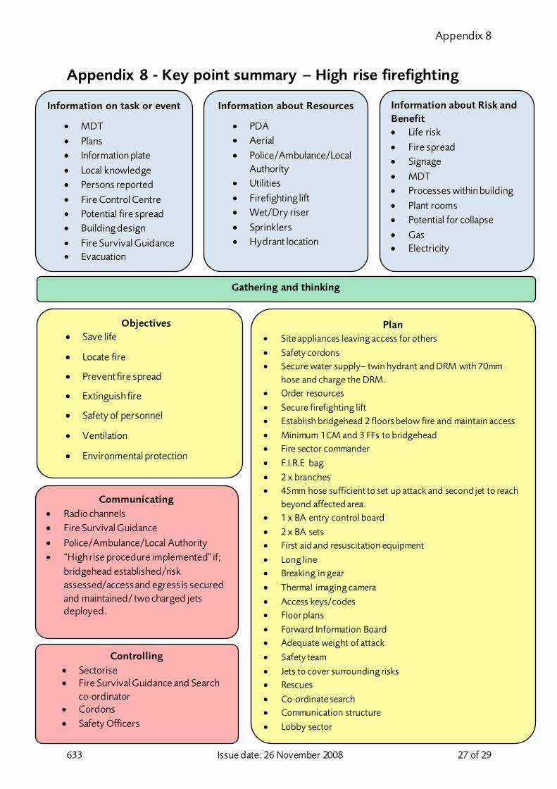
Appendix 8 - Key point summary – High rise firefighting
Information about Resources
• PDA • Aerial • Police/Ambulance/Local
Authority • Utilities • Firefighting lift • Wet/Dry riser • Sprinklers • Hydrant location
Information about Risk and Benefit • Life risk • Fire spread • Signage • MDT • Processes within building • Plant rooms • Potential for collapse • Gas • Electricity
Gathering and thinking
Objectives • Save life
• Locate fire
• Prevent fire spread
• Extinguish fire
• Safety of personnel
• Ventilation
• Environmental protection
Plan • Site appliances leaving access for others
• Safety cordons • Secure water supply– twin hydrant and DRM with 70mm
hose and charge the DRM. • Order resources
• Secure firefighting lift • Establish bridgehead 2 floors below fire and maintain access
• Minimum 1CM and 3 FFs to bridgehead • Fire sector commander
• F.I.R.E bag
• 2 x branches • 45mm hose sufficient to set up attack and second jet to reach
beyond affected area. • 1 x BA entry control board
• 2 x BA sets • First aid and resuscitation equipment
• Long line • Breaking in gear
• Thermal imaging camera
• Access keys/codes • Floor plans
• Forward Information Board • Adequate weight of attack
• Safety team
• Jets to cover surrounding risks • Rescues
• Co-ordinate search • Communication structure
• Lobby sector
Communicating • Radio channels • Fire Survival Guidance • Police/Ambulance/Local Authority • “High rise procedure implemented” if;
bridgehead established/risk assessed/access and egress is secured and maintained/ two charged jets deployed.
Information on task or event
• MDT • Plans • Information plate • Local knowledge • Persons reported • Fire Control Centre • Potential fire spread • Building design • Fire Survival Guidance • Evacuation
Controlling • Sectorise • Fire Survival Guidance and Search
co-ordinator • Cordons • Safety Officers

633 Issue date: 26 November 2008 28 of 29
Document history
Assessments
An equality, sustainability or health, safety and welfare impact assessment and/or a risk assessment was last completed on:
EIA 15/10/2008 SDIA 15/11/2011 HSWIA RA 17/05/2013
Audit trail
Listed below is a brief audit trail, detailing amendments made to this policy/procedure.
Page/para nos. Brief description of change Date Throughout This policy has been protectively marked. 21/06/2011
Throughout This policy has been reviewed as current. Minor changes have been made throughout and the Key Point Summary has been updated to reflect current procedure. Please read to familiarise yourself with the content.
18/11/2011
Throughout Minor wording corrections added. Sections now correctly referenced.
23/11/2011
Page 16, para 8 Updated reference to form 5566 as this has now been withdrawn and replaced with a new procedure.
10/05/2012
Pages 11 and 12 Cross reference links to policies added to paragraphs 7.30, 7.35 and 7.37.
13/12/2012
Page 14 Reference page has been updated with additional policy numbers.
13/02/2012
Throughout PN521 has been replaced with PN800. 22/02/2013
Page 12 Changes made following review of policy in response to an SAI event.
26/11/2013
Page 1 & page 22
Changed ‘Protect’ to ‘Official’ in line with new security marking scheme.
07/08/2014
Page 2and 22 Key point summary removed from page 2 and KPS flowchart added as appendix 7.
28/08/2014
Page 2 Para 1.1 Page4 Para 2.29
Reference made to PN 793 Compartment Firefighting. Minor amendment to wording.
11/09/2014
Page 21 ‘Subject list’ table - template updated. 29/01/2015
Throughout Policy updated to reflect national GRA 3.2. and associated LFB risk assessment
01/06/2015
Risk Assessment Throughout
Amended to include controlled dividing breeching. Updated to reflect introduction of Fire Initial Response Equipment (FIRE) Bag.
10/07/2017

633 Issue date: 26 November 2008 29 of 29
Subject list
You can find this policy under the following subjects.
Cable entanglement Buildings and Structures
Incident Management Flowchart - Key Point Summary (KPS)
Wet rising main Tower blocks
Special risks Mobile Data Terminals (MDT)
High Rise Buildings High Rise
Firefighting shafts Firefighting lift
Firefighting - Special risk areas Firefighting - Buildings
Firefighting Dry Rising Mains
GRA 3.2
Freedom of Information Act exemptions
The reason this policy has been securely marked:
Considered by: (responsible work team)
FOIA exemption Security marking classification
Operational Procedures Fully exempt, see FOIA592.1 request.
Official – Ops Security Official – Health & Safety