Embed Size (px)
Citation preview

National Institute Of TechnologyRourkela
Undergrad Thesis
High Security Image Encryption By 3Stage Process
Submitted By:
Sourav Kumar Agrawa]l
Supervisor:
Prof. B.Majhi
A thesis submitted in fulfilment of the requirements
for the degree of Bachelor in Technology(B. Tech.)
in the
Computer Science Engineering
National Institute Of Technology Rourkela
May 2014

Declaration of Authorship
I, Sourav Kumar Agrawal, declare that this thesis titled, ’High Security Image Encryp-
tion By 3 Stage Process’ and the work presented in it are my own. I confirm that:
� This work was done wholly or mainly while in candidature for a research degree
at this University.
� Where any part of this thesis has previously been submitted for a degree or any
other qualification at this University or any other institution, this has been clearly
stated.
� Where I have consulted the published work of others, this is always clearly at-
tributed.
� Where I have quoted from the work of others, the source is always given. With
the exception of such quotations, this thesis is entirely my own work.
� I have acknowledged all main sources of help.
� Where the thesis is based on work done by myself jointly with others, I have made
clear exactly what was done by others and what We have contributed myself.
Signed:
Signed:
Date:
i

Certificate
This is to certify that the thesis entitled High Security Image Encryption By 3
Stage Process by Sourav Kumar Agrawal in partial fulfillment of the requirements
for the award of Bachelor of Technology Degree in Computer Science and Engineering
at the National Institute of Technology, Rourkela, is an authentic work carried out by
them under my supervision and guidance. To the best of my knowledge, the matter
embodied in the thesis has not been submitted to any other university / institute for
the award of any Degree or Diploma.
Prof. B.Majhi
Dept. of Computer Science and Engineering
National Institute of Technology Rourkela
Rourkela-769008

Acknowledgements
I am indebted to my guide Prof. B.Majhi for giving me an opportunity to work under his
guidance. Like a true mentor, he motivated and inspired me through the entire duration
of our work, without which this project could not have seen the light of the day.
I convey our regards to all the other faculty members of Department of Computer Science
and Engineering, NIT Rourkela for their valuable guidance and advices at appropriate
times. I would like to thank my friends for their help and assistance all through this
project.
Last but not the least, I express our profound gratitude to the Almighty and our parents
for their blessings and support without which this task could have never been accom-
plished.
Sourav Kumar Agrawal
110CS0558
Dept. of Computer Science and Engineering
National Institute of Technology Rourkela
iii

Abstract
As a result of the development of computer network technology, communication of in-
formation through personal computer is becoming more convenient. Meanwhile, it also
gives hackers opportunities to attack the network. Therefore the security is now an
important issue for multimedia communications.
Image compression and image encryption are pivotal to proper storage and transmission
of images. Simultaneous image compression and encryption aims at achieving enhanced
bandwidth utilization and security at the same time.
The concepts used here are : Chinese Reminder Theorem, Chaotic map, Bit plane mix-
ing.
The use of chaotic mixing increases the security of the proposed method and provides
the additional feature of imperceptible encryption of the image owner logo in the host
image. The image coding results, calculated from actual image size and encoded im-
age file, are comparable to the results obtained through much more sophisticated and
computationally complex methods. In addition, the algorithm has been applied to the
scenario of image multiplexing in order to obtain enhanced level of security along with
compression. Here one layer of encryption involves bit plane mixing. Encrypted and
compressed image is applied to hiding algorithms. The idea behind our proposed method
is, the cover image will be altered based upon the secret image. The secret image will
be split into number of blocks and these blocks will be shuffled intellectually and then
it will be merged with the cover image to generate the Segno image. Our proposed
method, originally designed for dealing with color images, but also be extended to for
grayscale images. Experimental results show that our proposed method improves the
security and makes the information hacking hard.

Contents
Declaration of Authorship i
Certificate ii
Acknowledgements iii
Abstract iv
Contents v
List of Figures vi
1 Introduction 1
1.1 What is Image Encryption ? . . . . . . . . . . . . . . . . . . . . . . . . . . 1
1.1.1 place . . . . . . . . . . . . . . . . . . . . . . . . . . . . . . . . . . . 1
1.1.2 Value . . . . . . . . . . . . . . . . . . . . . . . . . . . . . . . . . . 2
1.2 Why new methods for image Encryption.? . . . . . . . . . . . . . . . . . . 2
1.3 3 Stage . . . . . . . . . . . . . . . . . . . . . . . . . . . . . . . . . . . . . 2
2 Image Encryption 4
2.1 Introduction to Image Encryption(IE) . . . . . . . . . . . . . . . . . . . . 4
2.2 IE Algorithm . . . . . . . . . . . . . . . . . . . . . . . . . . . . . . . . . . 4
2.2.1 Chaotic Mapping . . . . . . . . . . . . . . . . . . . . . . . . . . . . 5
3 Image Compresscryption 9
3.1 Introduction to Image Compresscryption . . . . . . . . . . . . . . . . . . . 9
3.1.0.1 Merits of CRT . . . . . . . . . . . . . . . . . . . . . . . . 11
3.2 Algorithm Procedure . . . . . . . . . . . . . . . . . . . . . . . . . . . . . . 11
3.2.1 Loss less coding . . . . . . . . . . . . . . . . . . . . . . . . . . . . . 12
4 Image Hiding 14
5 Results And Discussion 17
6 Security and Analysis 22
6.1 In terms of Encryption . . . . . . . . . . . . . . . . . . . . . . . . . . . . . 22
v

Contents vi
6.1.1 Key space . . . . . . . . . . . . . . . . . . . . . . . . . . . . . . . . 22
6.1.2 Statistical Analysis . . . . . . . . . . . . . . . . . . . . . . . . . . . 23
6.2 In terms of compresscryption . . . . . . . . . . . . . . . . . . . . . . . . . 23
7 Conclusion And Future Scope 25
7.1 Future Scope . . . . . . . . . . . . . . . . . . . . . . . . . . . . . . . . . . 25
Bibliography 25
List of Figures
2.1 Mapping of image Pixels . . . . . . . . . . . . . . . . . . . . . . . . . . . . 5
2.2 Left Mapping . . . . . . . . . . . . . . . . . . . . . . . . . . . . . . . . . . 5
2.3 Left Mapping . . . . . . . . . . . . . . . . . . . . . . . . . . . . . . . . . . 6
2.4 Delamination of Image . . . . . . . . . . . . . . . . . . . . . . . . . . . . . 7
2.5 (Block Diagram of Encryption Process) . . . . . . . . . . . . . . . . . . . 8
3.1 Flow Diagram of Compresscryption . . . . . . . . . . . . . . . . . . . . . . 9
3.2 Block Diagram of Compresscryption . . . . . . . . . . . . . . . . . . . . . 11
4.1 Block Diagram of Compresscryption . . . . . . . . . . . . . . . . . . . . . 15
5.1 Base image And Secret Image . . . . . . . . . . . . . . . . . . . . . . . . . 17
5.2 Hybrid Image . . . . . . . . . . . . . . . . . . . . . . . . . . . . . . . . . . 18
5.3 Encryption using key 1234 . . . . . . . . . . . . . . . . . . . . . . . . . . . 18
5.4 Encryption using key 1010 . . . . . . . . . . . . . . . . . . . . . . . . . . . 19
5.5 Output Compressed Array TR1 . . . . . . . . . . . . . . . . . . . . . . . . 19
5.6 Output Compressed Array TR2 . . . . . . . . . . . . . . . . . . . . . . . . 20
5.7 Memory of Different variable in the program . . . . . . . . . . . . . . . . 21
6.1 Correlation of pixels before and after encryption . . . . . . . . . . . . . . 23
vii

Chapter 1
Introduction
Images play a pivotal role in several applications like remote sensing, biomedical, video
conferencing. Interest in digital image processing methods stems from the following
principal application areas: improvement of pictorial information for human interpreta-
tion; and processing of image data for storage and transmission for machine perception.
Whenever an image has to be transmitted, two significant issues need to be addressed.
One is to accommodate the image within the allotted bandwidth and the other is to
ensure secure transmission of images. Image compression and image encryption are two
fundamental image processing techniques extensively used towards meeting the require-
ment of efficient utilization of bandwidth and security.
1.1 What is Image Encryption ?
Image Encryption means changing convert the image into unreadable format.
This can be done by modifying the image pixels in terms of its (place , Value) in order to
protect the information. Their can be many technique to encrypt image which involve
may be key mapping or hiding of fusion of image ,but basically the image is changed at
pixel level i.e value of pixels or their position in original array.
1.1.1 place
Encrypting the image by following particular steps which involves changing the image
places only. These process may involve methods like Scrambling, Chaotic Mapping,
Inversion. These Process can be followed with set of keys which can decide the order
of these algorithm that could be followed for encryption.As pixels remains in the image
itself, it may be vulnerable to attack of crypt analyst attacks but using variable length
1

Chapter 1. Introduction 2
key we can enhance the security.
The correlation between pixels here is reduced.
1.1.2 Value
This Process involves changing in the image pixel values. The methods that can be used
are Bit plane mixing, Multiplexing, Compressing. The correlation between base
and encrypted image is much less in this process.
1.2 Why new methods for image Encryption.?
� More and more images are transmitted over the Internet with the fast develop-
ments of information technology. How to protect images has increasingly become
an important issue. The encryption is an important tool to protect important
information from attackers.
� Some intrinsic features of images, such as Bulk Data Capacity ,High Corre-
lation Among Pixels, And DES or AES methods incur large number of
computational cost and show poor analysis, prevalent encryption technol-
ogy such as DES and RSA, and other algorithms are not absolutely fit to image
encryption.
1.3 3 Stage
The High Security concept here can be seen in 3 steps :
� Image Hiding
� Image Encryption
� Image Compresscryption(Compress +Encrypt)
For Encryption chaotic map are used for scrambling the image pixels. It can encrypt
images by processing image stretch and fold process. Firstly a square image is divided
into two isosceles triangles according the diagonal. Utilizing the difference of the pixel
numbers of two adjacent columns of the triangles, each pixel in a column is inserted to
the adjacent column. The plain image can then be stretched to a line. This line of image
value can then be converted to 2D array for i.e inform of encrypted image.

Chapter 1. Introduction 3
Some of available scheme for image compression are JPEG-LS, SPIHT, JPEG2000,
CALIC etc. Transform like DCT or DWT are generally applied currently. The avail-
able techniques uses the transformation of pixels but the proposed method here doesn’t
transform rather it uses basic mathematical operations.Second, the number theoretic
approach provides an additional advantage of image encryption, simultaneously, using
keys, making the transmitted data both short and secure.
And in case of image hiding, the information will be in the form of image. This image
is said to be the secret image. Hence we are providing security in the form of image.
Fig.1 shows how the process involved in information hiding. The secret image is first
splited into 9 parts. Appropriate target image have to be selected. The selection process
depends upon the database. The target image should be picked from the database and
that target image should be a proper match for the source image. The target image
we have chosen should be double in size then the source image. Mosaic image is then
created. The tile images can be used repeatedly. By using a secret key, the mosaic
image has been put under the process and thus we are gaining the secret image after
embedding process. The hacker without knowing the key cannot reconstruct back the
mosaic image and thus the secret image cannot be viewed.

Chapter 2
Image Encryption
2.1 Introduction to Image Encryption(IE)
Image encryption has applications in inter-net communication, multimedia systems,
medical imaging, tele medicine, and military communication, .However there are prob-
lem in terms of security level, speed, and resulting stream size metrics. Since the dynamic
response of the chaotic system is sensitively to the initial values and parameters of the
chaotic system, a great number of researches apply chaotic sequences to encrypt images
for the purpose of communication security . It is a convenient and fast method by con-
ducting a first order chaotic system to encrypt digital images. The proposed method
chaotic maps which can overcome the periodicity of Arnold map and is more security;
besides, it is robust to the common signal attacks.[2]
Many Algorithm for IE has been proposed,some which are Based on Position permuta-
tion , value transformation like Block based transformation, Self invertible key matrix,
Hill cipher,Hash function. In my proposed method Left and right mapping of image
with a sequence defined by user key(secret) is used for Encryption.
2.2 IE Algorithm
To Encrypt an image here 2 methods are used.
1. Chaotic Mapping 2. Bit Plane Mixing
4

Chapter 2. Image Encryption 5
Figure 2.1: Mapping of image Pixels
Figure 2.2: Left Mapping
2.2.1 Chaotic Mapping
Concept
Basically it scrambles the images following a particular algorithm and reversing it can
find the base image. It can be seen from the following: The N × N Image is divided
diagonally into two maps(Left and Right).Left map means The Image is first transformed
into a line of pixels and then shuffled using algorithm ,After that again it is converted
to N ×N image(Encrypted). It can be inferred from figure.1
To explain it more clearly, consider the following example.
Consider the image has 4 × 4 pixels, i.e. N=4. The process of the map is shown in
Figure. 2. First a square image is divided into two isosceles triangles according diagonal.
Utilizing the difference of the pixel numbers of two adjacent columns of the triangles,
each pixel in a column is inserted to the adjacent column.[2]
The pixel [3,3] can be inserted before the pixel [2,2], pixel [2,3] can be inserted between
pixels [2,2] and [1,2], pixel [1,3] can be inserted between pixels [1,2] and [0,2] and so on.
So the pixels join to a line: [3,3], [2,2], [2,3], [1,2], [1,3], [0,2], . . . .[2]

Chapter 2. Image Encryption 6
Figure 2.3: Left Mapping
Algorithm
Left Mapping
� L[(N+j+2)(N-j-1)/2 + 2(j-1)]=A(I, j);
Where j¿=I, N-j is the odd number,
� L[(N+j+3)(N-j-2)/2 + 2(j-1)+1]=A(I, j);
Where j¿=I, N-j is the even number,
� L[(N2+N+(2N-j-1))*j)/2 + 2(N-i-1)]=A(I, j);
Where j¡i, N-j is the even number
� L[(N2+N+(2N-j))*(j-i))/2 + 2(N-i)-1]=A(I, j);
Where j¡I, N-j is the odd number,
Where. . . .. i=0,1,.......N-1
J=0,1,.........N-1 [2]
Algorithm for Right Mapping
� L[(N+j+2)(N-j-1)/2 + 2(j-1)]=A(I,N-1-j);
Where j¿=I, N-j is the odd number,
� L[(N+j+3)(N-j-2)/2 + 2(j-1)+1]=A(I, N-1-j);
Where j¿=I, N-j is the even number,
� L[(N2+N+(2N-j-1))*j)/2 + 2(N-i-1)]=A(I, N-1-j);
Where j¡i, N-j is the even number

Chapter 2. Image Encryption 7
� L[(N2+N+(2N-j))*(j-i))/2 + 2(N-i)-1]=A(I, N-1-j);
Where j¡I, N-j is the odd number,
Where. . . .. i=0,1,.......N-1
J=0,1,.........N-1 [2]
Output of Right Mapping can be seen from fig.3.
Bit Plane Mixing
The square image consists of N × N pixels with L gray levels. The gray level value of
each pixel A is in decimal which can be expressed as a binary number.
A = sumi=8i=1 Ki ∗ 2i
So we can split the plain-image into eight layers. As shown in Fig. 4, the first layer is
composed by the lowest coefficients of the binary number of image values; the second
layer is composed by the second coefficients. . . and so on.
Then ,the mapping (either left or right depending on key ) is applied to each plane of
bits and encrypted. These encrypted bit planes are then assembled and the encrypted
image is formed , which is to be sent into the channel. On the receiver side again these
plane are separated and reverse mapping is applied to get the original bit planes. The
concept of bit plane mixing can be understood from Fig 2.5
Figure 2.4: Delamination of Image

Chapter 2. Image Encryption 8
Figure 2.5: (Block Diagram of Encryption Process)
Chapter 3
Image Compresscryption
3.1 Introduction to Image Compresscryption
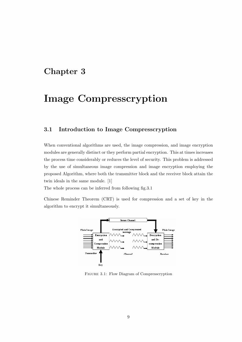
When conventional algorithms are used, the image compression, and image encryption
modules are generally distinct or they perform partial encryption. This at times increases
the process time considerably or reduces the level of security. This problem is addressed
by the use of simultaneous image compression and image encryption employing the
proposed Algorithm, where both the transmitter block and the receiver block attain the
twin ideals in the same module. [1]
The whole process can be inferred from following fig.3.1
Chinese Reminder Theorem (CRT) is used for compression and a set of key in the
algorithm to encrypt it simultaneously.
Figure 3.1: Flow Diagram of Compresscryption
9

Chapter 3. Image Compresscryption 10
Chinese Reminder Theorem (CRT)
The CRT is based on the solution of linear and modular congruencies and its generaliza-
tion in abstract algebra. Congruence is nothing more than a statement about divisibility.
It was first published in the 3rd to 5th centuries by Chinese mathematician Sun Tzu.
Theoram
If p and q are co-prime, then the system of equation
X ≡ a mod p , X ≡ b mod q
has unique solution for X modulo pq.
If we generalize this concepts it can as follows :
Considering n1, n2, n3, .......nm be m pairwise co-prime +ve Integers.Then their exist a
X for a given sequence of +ve integers a1, a2, a3, .......am solving the following system of
simultaneous congruence.
Furthermore, all solutions x of this system are congruent modulo the product, N =
n1, n2, n3, .......nk.
Hence,x ≡ y mod ni for all i such that 1 ≤ i ≤ k if and only if, x ≡ y mod N
Sometimes, the simultaneous congruence can be solved even if the ni ’s are not pairwise
co-prime. A solution x exists if and only if:
ai ≡ aj mod gcd(ni, nj) for all i and j
All solutions x are then congruent modulo the least common multiple of the ni.
� The Chinese Remainder Theorem can be used to increase efficiency by making use
of relatively small numbers in most of the calculation.
Chapter 3. Image Compresscryption 11
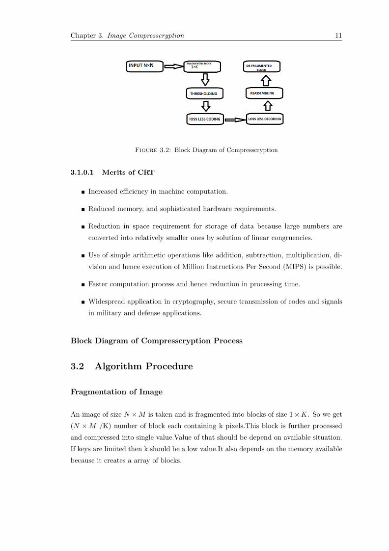
Figure 3.2: Block Diagram of Compresscryption
3.1.0.1 Merits of CRT
� Increased efficiency in machine computation.
� Reduced memory, and sophisticated hardware requirements.
� Reduction in space requirement for storage of data because large numbers are
converted into relatively smaller ones by solution of linear congruencies.
� Use of simple arithmetic operations like addition, subtraction, multiplication, di-
vision and hence execution of Million Instructions Per Second (MIPS) is possible.
� Faster computation process and hence reduction in processing time.
� Widespread application in cryptography, secure transmission of codes and signals
in military and defense applications.
Block Diagram of Compresscryption Process
3.2 Algorithm Procedure
Fragmentation of Image
An image of size N ×M is taken and is fragmented into blocks of size 1×K. So we get
(N × M /K) number of block each containing k pixels.This block is further processed
and compressed into single value.Value of that should be depend on available situation.
If keys are limited then k should be a low value.It also depends on the memory available
because it creates a array of blocks.
Chapter 3. Image Compresscryption 12
Thersholding
Each pixel r[i] in the block is divided by 16 to produce two half pixels of 4 bits each.
This process is called thresholding. Here threshold value is 4 bits. We can divide with
32 to get 4 half pixels with a threshold value 2.
Here threshold value depends on key length on number of keys and key length.If length
of key is unbounded then a high value of K can be taken.
a[i] = r[i] /16, i = i to K
a’[i] = r[i] mod 16, i = i to K.
Thus the input image is considered as a sequence of half pixels a[l,2,...K], a’[1,2,...K]
.
And the key sequence is a set of relatively prime(co-prime) numbers given by , n[l, 2.,K] ≥a[i]anda′[i].
So We have Block of Half Pixels i.e. Array a Array a’ (a[1,2,...k], a’[1,2,...k])
set of relatively Prime Integer i.e. Key Array n (n[1,2...k]) [1]
3.2.1 Loss less coding
The Coefficients of the CRT are calculated by generating N for each key value using P,
where P is the product of all the keys,
N[i]= P / n[i] where P = n[i].
Now the linear congruencies are generated by using the equation
N[i]*x[i]= 1(mod n[i]) ,where x[i] satisfies the above congruency
And C[i]= N[i]* x[i].
These stages are carried on prior to transmission, the values of C[i] can be generated
once the key is decided; hence they are calculated and stored in the system to be used
during transmission.
For the transmission of the image, the value of TR is determined for each block of
K half pixel values as follows.
TR = sum C[i] ∗ a(i) (Mod P) - Cipher Text (quotient)
TR′ = sum C[i] ∗ a′(i) (Mod P)- Cipher Text (Reminder)[1]
For K half pixel values, one TR and TR’ value is transmitted providing compression;
moreover, this value is dependent on the key used which incorporates encryption. This

Chapter 3. Image Compresscryption 13
is the most vital step of the algorithm as it ensures simultaneous encryption and com-
pression.
Loss less decoding
Decoding is done at the receiving end.The K half pixel values are generated from the
single value TR and TR’.
ar[i] = TR (mod n[i]) - Plain Text (quotient)
ar’[i] =TR’ (mod n[i]) Plain Text (remainder)
Reassemble
After we get the the half pixels they are assemble to make full block pixel.It can done
using following steps. s[i] = ar[i] * 16 + ar’[i] (s[i] return th ith block of image frag-
ment).[1]
Chapter 4
Image Hiding
Introduction to Image Hiding
The main purpose of image hiding is create confusion for any crypt analyst who tries
to get information. This can be done by providing him with dummy information i.e. a
base image but the real data image can be hidden in base image. Image hiding can meet
the requirements like security,imperceptibility,robustness,capacity,integrity.
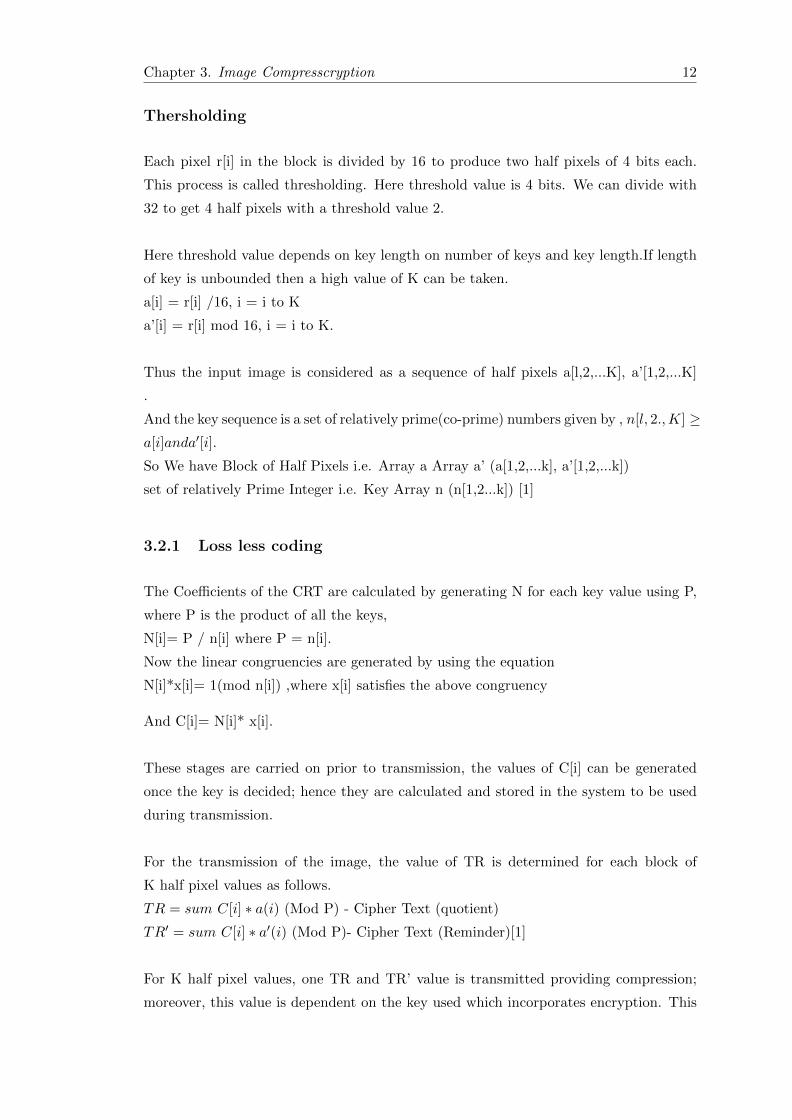
Image hiding here is accomplished through Multiplexing. Image multiplexing is the
process of transmitting two or more images simultaneously in a single channel which is
achieved by merging the images. And Merging is a technique by means of which the pixel
values of two separate images are scrambled so that the resultant image is meaningless.
Such images cannot be retrieved unless the order of scrambling is determined. This is
done in order to make image transmission more secure.
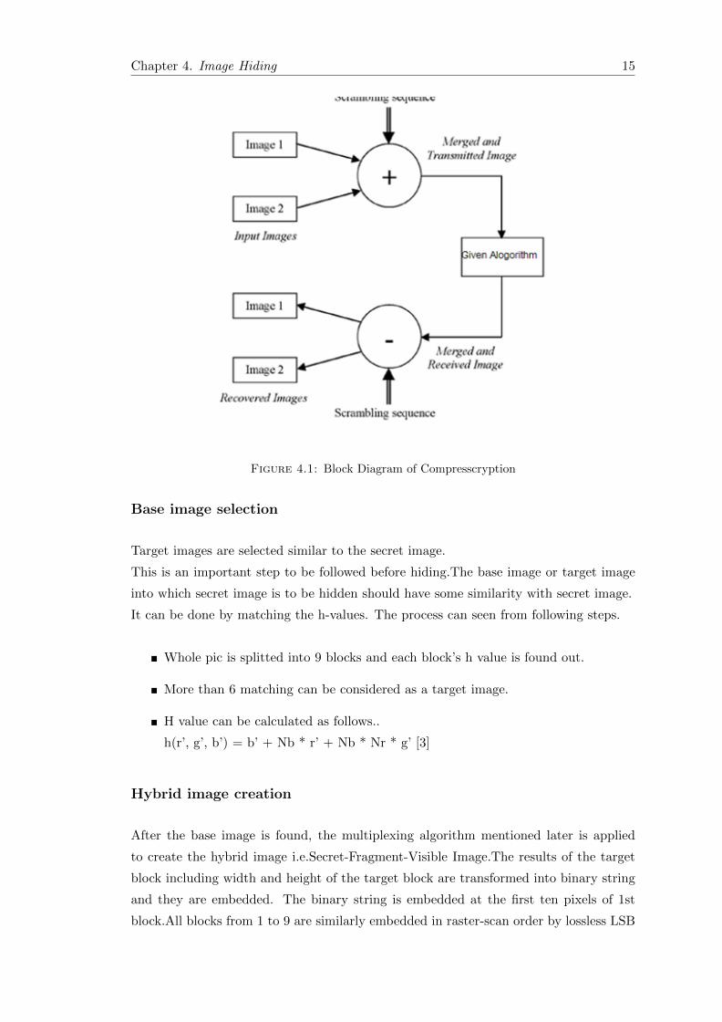
From fig 4.1 which is a Block Diagram of merging process the concept can be inferred.
Block Diagram of Multiplexing
In order to achieve enhanced security, two images can be merged (i.e. one image i
s hidden in other) so that when an intruder tries to intercept the image, it is not
knowledgeable to him.
Phases of Image Hiding
Image Hiding can be carried out in 2 steps.
14
Chapter 4. Image Hiding 15
Figure 4.1: Block Diagram of Compresscryption
Base image selection
Target images are selected similar to the secret image.
This is an important step to be followed before hiding.The base image or target image
into which secret image is to be hidden should have some similarity with secret image.
It can be done by matching the h-values. The process can seen from following steps.
� Whole pic is splitted into 9 blocks and each block’s h value is found out.
� More than 6 matching can be considered as a target image.
� H value can be calculated as follows..
h(r’, g’, b’) = b’ + Nb * r’ + Nb * Nr * g’ [3]
Hybrid image creation
After the base image is found, the multiplexing algorithm mentioned later is applied
to create the hybrid image i.e.Secret-Fragment-Visible Image.The results of the target
block including width and height of the target block are transformed into binary string
and they are embedded. The binary string is embedded at the first ten pixels of 1st
block.All blocks from 1 to 9 are similarly embedded in raster-scan order by lossless LSB

Chapter 4. Image Hiding 16
replacement.
As, here any key is not used for hiding, just the reverse LSB replacement can give the
base and secret image, so in next phase image encryption is applied.
Algorithm for Hiding
� Obtain the pixel values of both the images.
� Merge the MSB and LSB pixel to obtain half byte words.
� These 4 bit values are then given as inputs to the Described Compresscryption
algorithm.
� The encrypted and compressed pixels are transmitted.
� On reception the key is used to retrieve the pixel values.
� The MSB and LSB bits are re-arranged in order to obtain the original image.[2]
Chapter 5
Results And Discussion
Results of Hiding And Merging
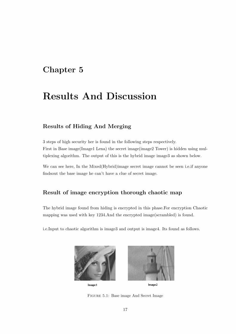
3 steps of high security her is found in the following steps respectively.
First in Base image(Image1 Lena) the secret image(image2 Tower) is hidden using mul-
tiplexing algorithm. The output of this is the hybrid image image3 as shown below.
We can see here, In the Mixed(Hybrid)image secret image cannot be seen i.e.if anyone
findsout the base image he can’t have a clue of secret image.
Result of image encryption thorough chaotic map
The hybrid image found from hiding is encrypted in this phase.For encryption Chaotic
mapping was used with key 1234.And the encrypted image(scrambled) is found.
i.e.Input to chaotic algorithm is image3 and output is image4. Its found as follows.
Figure 5.1: Base image And Secret Image
17

Chapter 5. Results And Discussion 18
Figure 5.2: Hybrid Image
Figure 5.3: Encryption using key 1234
Here key length is variable so for different key, we get a different set of encrypted image.
For example if we use key 1010 then the output image would be like image 5.
Result of image Compresscryption (CRT)
The encrypted image is then compressed through Compresscryption algorithm.
As the output of this algorithm, we discussed before is a compressed array i.e. Tr1 and
Tr2 which contains compressed value for a block(K) no. of half-pixels value each.
5 columns content of Tr1 is shown which shows compressed value of half-pixels (0-450).

Chapter 5. Results And Discussion 19
Figure 5.4: Encryption using key 1010
Figure 5.5: Output Compressed Array TR1

Chapter 5. Results And Discussion 20
Figure 5.6: Output Compressed Array TR2
For other Half pixels Compressed array is TR2 and content of(0 to 450th pixels) is shown
in following figure.
Here we can also see image is compressed. i.e. we have to sent an image of 11KB(Hybrid
image(3)) but after compressing we got an array which 7.99 KB. Compress factor here
is 1.37 .
It can be inferred from figure 5.7.

Chapter 5. Results And Discussion 21
Figure 5.7: Memory of Different variable in the program

Chapter 6
Security and Analysis
In terms of Hiding
First secret image is hidden in the base image, so if anyone tries to find out the secret
image then he would get the false image.
Suppose if the reverse order LSB replacement has been known, one can find the secret
image. In order to avoid this, we are providing additional encryption in stage2. i.e.
without a key it cannot decrypt the secret image.
6.1 In terms of Encryption
6.1.1 Key space
Since the length of the key of the map has no limit, its key space can be calculated
according to the length of the key. Suppose the keys are represented in binary bits. The
relationship between the key space size and the key length is shown in TABLE I.
22
Chapter 6. Security And Analysis 23
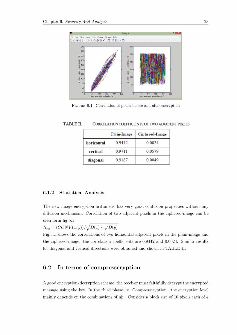
Figure 6.1: Correlation of pixels before and after encryption
6.1.2 Statistical Analysis
The new image encryption arithmetic has very good confusion properties without any
diffusion mechanism. Correlation of two adjacent pixels in the ciphered-image can be
seen form fig 5.1
Rxy = (CONV (x, y))/√D(x) ∗
√D(y)
Fig.5.1 shows the correlations of two horizontal adjacent pixels in the plain-image and
the ciphered-image: the correlation coefficients are 0.9442 and 0.0024. Similar results
for diagonal and vertical directions were obtained and shown in TABLE II.
6.2 In terms of compresscryption
A good encryption/decryption scheme, the receiver must faithfully decrypt the encrypted
message using the key. In the third phase i.e. Compresscryption , the encryption level
mainly depends on the combinations of n[i]. Consider a block size of 10 pixels each of 4
Chapter 6. Security And Analysis 24
bits in length. Here, a sequence of 10 keys each 6 bits in length is employed. Then the
maximum number of distinct key sequence ‘l’ is factorial (10).
The 40 bit pixel block is operated with 60 bit key sequence to obtain an upto-60 bit
cipher text block, During decoding, the same combination of n[i], which was selected for
encoding, should be applied correctly. The 60 maximum tryouts by an eavesdropper to
crack the key is 260∗l.

Chapter 7
Conclusion And Future Scope
Conclusion
A new image encryption arithmetic based on the chaotic mapping is proposed. The
arithmetic designs a method of key generation and utilizes the map to shuffle the posi-
tions of image pixels. The experimental tests have been carried out and the results show
the efficiency of the arithmetic.
A technique for simultaneous image compression and image encryption using number
theoretic paradigm is developed. Two dimensional encoding operation performed by
the proposed method is shown to be simple in terms of computational complexity. The
amount of compression achieved for different images using the proposed method is com-
parable with that of the conventional methods and also high level of security is provided
to the transmitted images.it is seen by applying multiplexing and image hiding secu-
rity level can further be enhanced. The results obtained illustrate that the proposed
algorithm provides a new coding technique which has the features of coding benefits
depending on the statistics of the image, inbuilt encryption module to enable secure
transmission and less system complexity.
7.1 Future Scope
� The algorithm can be extended to higher levels of encryption and compression by
increasing the key length. Also, specialized hardware can be developed for the
transmission and reception modules, to calculate the computation time.
� • Multiple Image hiding can be done in a single base image which can create
confusion for any crypt analyst.
25

Bibliography
[1] Vikram Jagannathan’, Aparna Mahadevan2 Number Theory Based Image Compres-
sion Encryption and Application to Image Multiplexing’- 2007. pp.59-64.
[2] Feng Huang, Chao Wang. A New Image Encryption Arithmetic Based on a Three-
dimensional Map’ - vol. 58, no. 7, pp. 83-91, 2001
[3] R.Janani, P.G Sch olar, Image Hiding Technique Based On Similarity Measure for
Networks with High Security Risk’ - VelTech MultiTech University Krishnagiri, India
Chennai,2009
[4] C. K. Huang , H. H. Nien, Multi chaotic systems based pixel shuffle for image en-
cryption,” Optics Communications 282 (2009) 2123–2127.
[5] ] R. Matthews. On the derivation of a ‘chaotic’ encryption algorithm,” Cryptologia,
vol. 13, no. 1, pp.29-42, 1989.
[6] G. Chen, Y. Mao, C. K. Chui.A symmetric image encryption scheme based on 3D
chaotic cat maps,” Chaos Solitons and Fractals, vol.21, pp.749-761, 2004
[7] Kenneth, R. C., Digital Image Processing, 2004 edition, Pre NTICE-Hall Interna-
tional, Inc.
[8] W.B. Pennebaker, J. Mitchell JPEG still image compression standard, 2001 edition,
New York: Van Nostrand Reinhold.
26