Embed Size (px)
Citation preview
MDOT RC-1563
High Skew Link Slab Bridge System with Deck Sliding over Backwall or Backwall Sliding over Abutments
FINAL REPORT – SEPTEMBER 2011
Western Michigan University Department of Civil & Construction Engineering
College of Engineering and Applied Sciences

ii
High skew link slab bridge system with deck sliding over backwall or backwall sliding over abutments
Intentionally left blank
iii
High skew link slab bridge system with deck sliding over backwall or backwall sliding over abutments
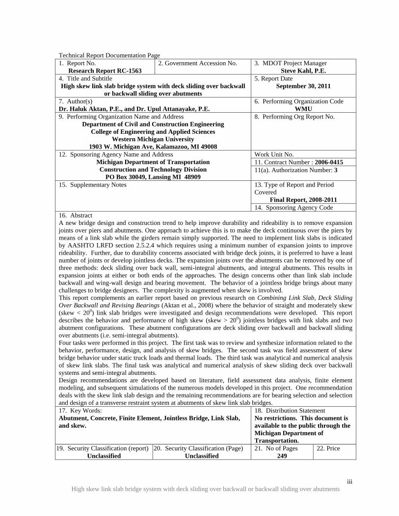
Technical Report Documentation Page
1. Report No.
Research Report RC-1563
2. Government Accession No. 3. MDOT Project Manager
Steve Kahl, P.E.
4. Title and Subtitle
High skew link slab bridge system with deck sliding over backwall
or backwall sliding over abutments
5. Report Date
September 30, 2011
7. Author(s)
Dr. Haluk Aktan, P.E., and Dr. Upul Attanayake, P.E.
6. Performing Organization Code
WMU
9. Performing Organization Name and Address
Department of Civil and Construction Engineering
College of Engineering and Applied Sciences
Western Michigan University
1903 W. Michigan Ave, Kalamazoo, MI 49008
8. Performing Org Report No.
12. Sponsoring Agency Name and Address
Michigan Department of Transportation
Construction and Technology Division
PO Box 30049, Lansing MI 48909
Work Unit No.
11. Contract Number : 2006-0415
11(a). Authorization Number: 3
15. Supplementary Notes 13. Type of Report and Period
Covered
Final Report, 2008-2011
14. Sponsoring Agency Code
16. Abstract
A new bridge design and construction trend to help improve durability and rideability is to remove expansion
joints over piers and abutments. One approach to achieve this is to make the deck continuous over the piers by
means of a link slab while the girders remain simply supported. The need to implement link slabs is indicated
by AASHTO LRFD section 2.5.2.4 which requires using a minimum number of expansion joints to improve
rideability. Further, due to durability concerns associated with bridge deck joints, it is preferred to have a least
number of joints or develop jointless decks. The expansion joints over the abutments can be removed by one of
three methods: deck sliding over back wall, semi-integral abutments, and integral abutments. This results in
expansion joints at either or both ends of the approaches. The design concerns other than link slab include
backwall and wing-wall design and bearing movement. The behavior of a jointless bridge brings about many
challenges to bridge designers. The complexity is augmented when skew is involved.
This report complements an earlier report based on previous research on Combining Link Slab, Deck Sliding
Over Backwall and Revising Bearings (Aktan et al., 2008) where the behavior of straight and moderately skew
(skew < 200) link slab bridges were investigated and design recommendations were developed. This report
describes the behavior and performance of high skew (skew > 200) jointless bridges with link slabs and two
abutment configurations. These abutment configurations are deck sliding over backwall and backwall sliding
over abutments (i.e. semi-integral abutments).
Four tasks were performed in this project. The first task was to review and synthesize information related to the
behavior, performance, design, and analysis of skew bridges. The second task was field assessment of skew
bridge behavior under static truck loads and thermal loads. The third task was analytical and numerical analysis
of skew link slabs. The final task was analytical and numerical analysis of skew sliding deck over backwall
systems and semi-integral abutments.
Design recommendations are developed based on literature, field assessment data analysis, finite element
modeling, and subsequent simulations of the numerous models developed in this project. One recommendation
deals with the skew link slab design and the remaining recommendations are for bearing selection and selection
and design of a transverse restraint system at abutments of skew link slab bridges.
17. Key Words:
Abutment, Concrete, Finite Element, Jointless Bridge, Link Slab,
and skew.
18. Distribution Statement
No restrictions. This document is
available to the public through the
Michigan Department of
Transportation.
19. Security Classification (report)
Unclassified
20. Security Classification (Page)
Unclassified
21. No of Pages
249
22. Price

iv
High skew link slab bridge system with deck sliding over backwall or backwall sliding over abutments
Intentionally left blank
High Skew Link Slab Bridge System with Deck Sliding over Backwall or Backwall
Sliding over Abutments
Project Manager: Mr. Steve Kahl, P.E.
Submitted to:
Submitted by
Dr. Haluk Aktan, P.E. Professor & Chair (269) – 276 – 3206 [email protected]
Dr. Upul Attanayake, P.E. Assistant Professor (269) – 276 – 3217 [email protected]
Western Michigan University Department of Civil & Construction Engineering
College of Engineering and Applied Sciences Kalamazoo, MI 49008
Fax: (269) – 276 – 3211

vi
High skew link slab bridge system with deck sliding over backwall or backwall sliding over abutments
Intentionally left blank

vii
High skew link slab bridge system with deck sliding over backwall or backwall sliding over abutments
DISCLAIMER
The content of this report reflects the views of the authors, who are responsible for the facts
and accuracy of the information presented herein. This document is disseminated under the
sponsorship of the Michigan Department of Transportation in the interest of information
exchange. The Michigan Department of Transportation assumes no liability for the content
of this report or its use thereof.

viii
High skew link slab bridge system with deck sliding over backwall or backwall sliding over abutments
Intentionally left blank

ix
High skew link slab bridge system with deck sliding over backwall or backwall sliding over abutments
ACKNOWLEDGEMENTS
This project is funded by the Michigan Department of Transportation. The authors would
like to acknowledge the support and effort of Mr. Steve Kahl for initiating this research. The
authors also wish to acknowledge the continuing assistance of the Research Advisory Panel
(RAP) members in contributing to the advancement of this study. Contribution of graduate
students Abdul Mohammed, Alp Servi, Duy Nguyen, Michael Romkema, and Mohamed
Rusthi for the successful completion of this study is highly appreciated.

x
High skew link slab bridge system with deck sliding over backwall or backwall sliding over abutments
Intentionally left blank
xi
High skew link slab bridge system with deck sliding over backwall or backwall sliding over abutments
EXECUTIVE SUMMARY
INTRODUCTION
The new bridge design trend is to avoid having expansion joints over piers and abutments to
prevent premature deterioration of bridges due to faulty joints. For this purpose joints over
the piers are eliminated using link slabs where the deck is continuous and the underlying
girders are simply supported. The expansion joints over the abutments are also eliminated by
allowing the deck to slide over the backwall or by allowing the deck-backwall combined
system to slide over the abutment (semi-integral abutments). As a result, the movement of
the superstructure is transferred to the ends of the approach slab that sits on a sleeper slab.
This research was designed to respond to the concerns of the designers in terms of the design
of specific components of high skew jointless link slab bridges with deck sliding over
backwall or semi-integral abutment configurations.
The objectives of this study were identified as follows:
1. Study the behavior of high skew bridge structural system by load testing and
analytical modeling and analysis.
2. Develop finite element models of selected components, or combinations of several
components, of the link slab bridge deck system with deck sliding over backwall and
semi-integral abutment to understand the behavior and interaction between
components under various load conditions, including volume change load.
3. Develop recommendations for changes or modifications to the design of the link slab,
and bearings, abutment types, and lateral restraint systems of bridges with link slabs.
To satisfy the objectives, this project was organized into four main tasks: literature review,
field assessment of skew bridge behavior under static truck loads and thermal loads,
analytical and numerical analysis of skew link slabs, and analytical and numerical analysis of
skew sliding deck over backwall systems and semi-integral abutments.
xii
High skew link slab bridge system with deck sliding over backwall or backwall sliding over abutments
LITERATURE REVIEW
Literature on the following topics was reviewed: skewed bridge behavior under gravity
loading, skewed bridge behavior under volume change loads, design challenges of
skewed/jointless bridges, and performance of skew/ jointless bridges. A summary of key
points identified through literature review is given below:
1. Skewed bridges with semi-integral abutments would tend to rotate about an axis
normal to their horizontal plane. The rotation is due to the passive pressure
developed behind the backwall under thermal expansion. Deck extensions also have
a tendency to develop in-plane rotations but not as critical as semi-integral systems.
In both deck extension and semi-integral systems, the rotation may be affected by the
approach slab-base interface friction, the shearing resistance of the elastomers in the
bearings, and by the compressive resistance of fillers used in the movable joints
between the superstructure and wingwalls.
2. The current MDOT deck sliding over backwall system uses Expanded polystyrene
(EPS) in between deck and backwall to introduce the sliding surface. The EPS elastic
strain limit is very small and can deform beyond the elastic limit under deck self-
weight and live loads. Further, peak and residual friction coefficients between EPS
and concrete are 2.3 and 1.0, respectively. Because of these reasons, neoprene pads
over backwall may be used. In addition, the polyethylene sheet used under approach
should be extended to the backwall face on the span side to minimize friction at the
interface.
3. A current semi-integral configuration used by Ontario and several State Highway
Agencies has the advantages of allowing the backwall to move independently from
the abutment, providing access space for bearing inspection, maintenance, and
replacement; and preventing backfill infiltration through the backwall.
4. Isolation of the backwall from its abutment requires developing specific design
details to constrain transverse movement of skew bridges. In that regard, placing the
backwall over the abutment and restraining transverse movement by placing the
xiii
High skew link slab bridge system with deck sliding over backwall or backwall sliding over abutments
wingwall against the backwall and deck, similar to the current MDOT semi-integral
details, provides many benefits if adequate measures are taken to minimize interface
friction and infiltration of backfill material through the joints. Use of EPS form
behind the backwall helps reduce passive earth pressure and prevent infiltration of
backfill material.
5. In order to allow the translation and rotation of skew bridges and provide sufficient
load capacity, plain elastomeric pad (PEP), fiberglass-reinforced pad (FRP), and
steel-reinforced elastomeric bearings or pads (SREB or SREP) are suitable for
support bearings for semi-integral and deck sliding over backwall bridges. Also,
polytetrafluorethylene (PTFE) sliding bearings can be combined with the support
bearing types stated above to accommodate large superstructure movements.
6. Rub plates, girder stops, or any other mechanism designed to resist large forces is
needed to control lateral movement of skew bridges.
7. With increasing backfill stiffness, forces at the wingwalls of high skew bridges
increase dramatically. EPS can be specified as a suitable backfill material for semi-
integral bridges to reduce passive pressure. However, an approach slab should not be
directly supported on EPS because of potential creep. EPS should also be protected
using geotextiles and gasoline containment geomembranes.
FIELD ASSESSMENT OF SKEW BRIDGE BEHAVIOR UNDER STATIC TRUCK
LOADS AND THERMAL EXPANSION
Bridge deflections and bearing translations were measured under static truck as well as
thermal loads. Measured girder deflections showed that girder end movements were
controlled by bearing friction. It is worth mentioning here that the bearing movements under
static truck loads were very small compared to allowance made at the design for thermal
expansion and contraction. The measured bearing movement under thermal expansion loads
from May to July indicates that the bearings are frozen and an in-plane twist of the deck
occurs due to bearing movement that is not expected at the design stage. Though there was
no damage to the superstructure and substructure of this 120 ft long single span bridge, this
xiv
High skew link slab bridge system with deck sliding over backwall or backwall sliding over abutments
behavior is critical when link slabs are implemented and the deck over the abutments is made
continuous. The observations highlight the importance of using durable bearings that are
capable of accommodating large deformation and a certain degree of rotation demands.
LINK SLAB ANALYSIS FOR DEVELOPING DESIGN GUIDELINES
Finite element analysis was utilized to understand the behavior of the jointless skew bridge
structural system with link slabs to verify the design assumptions and propose fine-tuning to
the current link slab design procedures to accommodate changing load demands due to
bridge skew. This task was accomplished by developing and analyzing refined finite element
models representing a two span bridge with a skew link slab. The major interest is how skew
affects the link slab moments. Skew reduction factors were calculated using moment ratios
and presented in Chapter 4. Skew reduction factors vary significantly with the live load
configurations, support configurations under the link slab, and with the direction of moment
(i.e., negative or positive). Skew reduction factors show that load demand decreases with
increasing skew.
A detailed link slab design example is given in Appendix C. The 450 skew bridge, in this
case, has a RHHR (Roller-Hinge-Hinge-Roller) support configuration, which develops the
largest link slab moments and forces under applied loads. Yet, the amount of required link
slab reinforcement is governed by the minimum reinforcement amount requirements of
AASHTO LRFD (2010).
Following are further key summary observations on analysis results:
1. The RHHR boundary condition develops significantly larger link-slab moments
compared to other support conditions.
2. NTG can be excluded from design load combination with HRRR and RRHR support
conditions.
3. NTG load case moments that develop in the link slab of bridges with zero skew and
RHHR support configuration, should be directly used in design without any reduction
for skew.
4. The negative moment design of a link slab with the RHHR support configuration is
governed by the combined effect of live and NTG loads.
xv
High skew link slab bridge system with deck sliding over backwall or backwall sliding over abutments
5. Positive moment design of a link slab with the RHHR support configuration is
governed by a PTG load.
6. Moment developed in a link slab under thermal gradient loads (PTG and NTG)
remains constant irrespective of span.
7. Providing the minimum reinforcement amount required in AASHTO LRFD Section
5.7.3.3.2 is adequate for the majority of skew link slabs with HRRR or RRHR support
configuration for spans up to 110 feet. However, additional reinforcement at the
bottom layer is needed to resist large tensile stresses developed near the boundaries of
the debonded region. A top layer of #6 bars at 4 in. spacing and bottom layer of #6
bars at 4 in. spacing are adequate for high skew link slabs. Proposed detail in standard
MDOT Bridge Design Guide format is presented in Appendix E.
8. Simplified analysis models are not able to represent three dimensional effects such as
positive moments under live load or negative moments under PTG. New analysis
models and procedures are required.
SKEW ABUTMENT ANALYSIS AND DESIGN GUIDELINES
This report provides a detailed analysis of two skew abutment configurations namely deck
sliding over backwall and semi-integral systems for a range of skew angles from 00 to 45
0
under loads and configurations specified in AASHTO (2010) and Michigan Bridge Design
Manual (MDOT 2005). Deck sliding over backwall and semi-integral abutment details
presented in Aktan et al. (2008) represented the basis of the FE models. These models were
modified to incorporate various bearing configurations and wingwalls. The following is a
summary of conclusions that are derived based on analysis results and information presented
in related literature and design specifications /guidelines
1. A bridge span with deck sliding over backwall or semi-integral abutments can be
analyzed as simply supported spans to calculate girder end rotations and translation
(expansion/contraction) demands.
2. Skew bridges expand and contract along the diagonal between acute corners. The
movement results in transverse forces at the bearings and other restraint systems. The
restraint force magnitudes become considerably larger if adequate tolerances are not

xvi
High skew link slab bridge system with deck sliding over backwall or backwall sliding over abutments
provided to accommodate the movements due to thermal loads. The situation
requires special consideration when link slabs are implemented over the piers, which
in turn increase the effective length of thermal expansion and contraction. Further,
the direction of bridge movement under expansion and contraction loads needs to be
restricted to the bridge axis. In plane twisting results in large stresses along the edge
of link slab (see Chapter 4). Link slab is also flexible under torsion compared to the
deck-girder integrated system. Hence, controlling bridge alignment is critical when
link slabs are implemented.
3. It is recommended that deck sliding over backwall abutments, is restrain the
transverse movement of the center girder end (for odd number of girders) or two
centermost girder ends (for even number of girders) using concrete keys with rub
plates (shown on Figure 5-8.). Also, larger tolerance is required for the slot in the sole
plate and bearings in order to accommodate the transverse movement of unrestrained
girder ends. Proposed detail in standard MDOT Bridge Design Guide format is
presented in Appendix F. The required formulations and variables for movement
calculations are presented with the drawings. The rub plate design procedure is based
on the VDOT Bridge Design Manual section 20.04 (2010) with modifications and
presented in Appendix G.
4. Transverse movement of bearings over the semi-integral abutment is facilitated by
increasing the tolerance of the slot at the bearing plate. Transverse restraint for
expansion thermal load is provided by a wingwall at the acute corner. Alignment of
semi-integral abutment bridge deck with backwall offset from the abutment is
managed under contraction thermal loads by placing a concrete key at the center
girder. Calculation of the transverse force on the wingwall is adopted from the
procedure described in VDOT (2010). Proposed detail in standard MDOT Bridge
Design Guide format is presented in Appendix H.
5. It is recommended that an EPS layer is placed behind the backwall of semi-integral
bridges. This will minimize the passive pressure and results in lower transverse
forces at the wingwall. Although the passive pressure coefficient of EPS is in reality
xvii
High skew link slab bridge system with deck sliding over backwall or backwall sliding over abutments
much lower than four (4), a coefficient of four (4) is recommended for conservative
design until additional supporting data is developed (VDOT (2010)). Further, the
equation given in VDOT (2010) section 20-06-6 can be used to calculate EPS layer
thickness (i.e., Eq. 2-2 in Chapter 2 section 2.4.4).
6. It is recommended that the maximum bearing tolerance in transverse direction is
limited to 0.25 in. Further investigations can be carried out analyzing the impact of
the increased fit tolerances of the girder position dowels on the bridge components.
7. Following link slabs are implemented, controlling friction at the approach slab
interfaces is very critical. Increased friction hinders bridge movement restricting
expansion bearing movement over the abutment. This results in stresses greater than
the concrete modulus of rupture under negative thermal loads. Hence, it is vital to
reduce friction at all the contract surfaces at the abutment and approach to facilitate
movement of the bridge under expansion and contraction thermal loads. To reduce
friction a 0.025 in. thick polyethylene sheet can be placed during construction over
the fill supporting the approach slab.
8. Bridge expansion length, which is the distance along the longitudinal axis measured
from abutment to the nearest fixed bearing, is a function of bridge length, width, and
skew. Expansion joint effective movement rating and allowable movement at
bearings are the limiting factors of bridge expansion length when link slabs are
implemented. Hence, the bridge expansion length should be calculated following the
procedure given in chapter 5 and be enforced when link slabs are implemented. As an
example, based on maximum strip seal joint width of 3 in. and expansion and
contraction thermal load of 115 0F, the following maximum expansion length are
recommended:
Straight concrete bridge ≤ 300 ft.
450 skew concrete bridge of 100 ft wide ≤ 200 ft.
Straight steel bridge ≤ 275 ft.
450 skew steel bridge of 100 ft wide ≤ 175 ft.
xviii
High skew link slab bridge system with deck sliding over backwall or backwall sliding over abutments
CONCLUSIONS
A literature review was performed, along with a field assessment of a skew bridge behavior
under static truck loads and thermal loads, an analytical and numerical analysis of skew link
slabs, and an analytical and numerical analysis of skew sliding deck over backwall systems
and semi-integral abutments tasks.
Current link slab design procedures do not incorporate skew effects. A design procedure was
developed following a detailed analysis of skew link slabs and the moment and force
envelopes for various boundary and load configurations. Two major findings are (1) moment
developed in a link slab under temperature gradient loads remains constant irrespective of
span and (2) moment developed in a link slab under live load decreases with increased span.
Analysis results verified that the minimum reinforcement amount required in AASHTO
LRFD Section 5.7.3.3.2 is adequate for the majority of skew link slabs with HRRR or RRHR
support configuration. However, additional reinforcement at the bottom layer is needed to
resist large tensile stresses that develop near the boundaries of the debonded region. A
detailed design example is presented in Appendix C. Proposed link-slab detail in standard
MDOT Bridge Design Guide format is presented in Appendix E. Three saw cuts are
recommended: one at each end of the link slab and one directly over the pier centerline.
The implementation of link slabs on deck sliding over backwall and semi-integral systems
presents specific challenges. This report provides a detailed analysis of two skew abutment
configurations namely deck sliding over backwall and semi-integral systems for a range of
skew angles from 00 to 45
0 under loads and configurations specified in AASHTO (2010) and
Michigan Bridge Design Manual (MDOT 2005). Bearing details, wingwall and concrete key
configurations, and abutment configurations were developed. Proposed detail in standard
MDOT Bridge Design Guide format is presented in Appendix F and H. All the required
mathematical relationships and variables are presented with the drawings. The rub plate
design procedure was adopted from VDOT Bridge Design Manual section 20.04 (2010) with
some modifications and presented in Appendix G.

xix
High skew link slab bridge system with deck sliding over backwall or backwall sliding over abutments
TABLE OF CONTENTS
ACKNOWLEDGEMENTS ............................................................................. ix
EXECUTIVE SUMMARY .............................................................................. xi
LIST OF TABLES ........................................................................................ xxiii
LIST OF FIGURES ........................................................................................xxv
1 INTRODUCTION ......................................................................................... 1
1.1 Overview .................................................................................................................... 1
1.2 Project Objectives and Tasks ..................................................................................... 2
1.3 Report Organization ................................................................................................... 2
2 STATE-OF-THE-ART LITERATURE REVIEW .................................... 5
2.1 Overview .................................................................................................................... 5
2.2 Skewed Bridge Behavior under Gravity Loading ...................................................... 7
2.2.1 Finite Element (FE) Simulation of Skew Bridge Behavior under Gravity
Loading ......................................................................................................... 9
2.3 Skewed Bridge Behavior under Volume Change Loads ......................................... 16
2.3.1 Skew Bridge Behavior under Thermal Loads .............................................. 21
2.4 Design Challenges of Skewed/Jointless Bridges ..................................................... 34
2.4.1 Length, Skew and Curvature Limits ............................................................ 34
2.4.2 Volume Change Loads and Behavior of Jointless Bridges .......................... 35
2.4.3 Semi-Integral Abutment Details .................................................................. 39
2.4.4 EPS Backfill ................................................................................................. 45
2.4.5 EPS-Concrete Interface Friction .................................................................. 49
2.4.6 Support Bearing Selection and Design ........................................................ 49
2.4.7 Deck Reinforcement Details with Skew ...................................................... 54
2.5 Field Performance of Skewed/Jointless Bridges...................................................... 56
2.6 Summary .................................................................................................................. 60
3 MODELING AND FIELD TESTING OF A HIGH SKEW BRIDGE .. 63
3.1 Objective and Approach .......................................................................................... 63
3.2 Bridge Description ................................................................................................... 63
xx
High skew link slab bridge system with deck sliding over backwall or backwall sliding over abutments
3.3 Abutment, Bearing, and Deck Condition ................................................................. 69
3.3.1 Abutment Condition..................................................................................... 69
3.3.2 Bearing Condition ........................................................................................ 69
3.3.3 Deck Condition ............................................................................................ 72
3.4 FE Modeling and Preliminary Analysis for Load Testing ....................................... 73
3.4.1 Bridge FE Modeling .................................................................................... 73
3.4.2 Truck Placement and Loading Configurations ............................................ 74
3.4.3 Calculated Bridge Deflections and Translations .......................................... 75
3.5 Measured Bridge Deflections and Translations ....................................................... 78
3.5.1 Field Measurement Equipment and Procedures .......................................... 78
3.5.2 Bridge Deflection ......................................................................................... 86
3.5.3 Bearing Translation ...................................................................................... 90
3.6 Summary .................................................................................................................. 98
4 LINK SLAB ANALYSIS AND DESIGN GUIDELINES ........................ 99
4.1 Overview and Objectives ......................................................................................... 99
4.2 Contact Simulation ................................................................................................... 99
4.3 Modeling and Analysis of a Link Slab Bridge ....................................................... 101
4.3.1 Overview and Objectives ........................................................................... 101
4.3.2 Prototype Bridge ........................................................................................ 101
4.3.3 Material Properties ..................................................................................... 102
4.3.4 Bridge Model Geometry ............................................................................ 102
4.3.5 Bridge Model Orientation .......................................................................... 104
4.3.6 Link Slab Length ........................................................................................ 105
4.3.7 FE Discretization of the Bridge Model ...................................................... 105
4.3.8 Skew Mesh ................................................................................................. 106
4.3.9 Contact Surfaces in the FE Model ............................................................. 109
4.3.10 Boundary Conditions ................................................................................. 110
4.3.11 Loads .......................................................................................................... 110
4.4 Sign Convention, Model Verification, and Results ............................................... 114
4.4.1 Overview .................................................................................................... 114
4.4.2 Sign Convention......................................................................................... 114
xxi
High skew link slab bridge system with deck sliding over backwall or backwall sliding over abutments
4.4.3 FE Model Verification ............................................................................... 115
4.4.4 Results ........................................................................................................ 116
4.4.5 Skew Link Slab Design Procedure ............................................................ 163
5 SKEW ABUTMENT ANALYSIS AND DESIGN GUIDELINES .......169
5.1 Overview and Objectives ....................................................................................... 169
5.2 Abutment Configurations and Analysis Models .................................................... 169
5.3 Lateral Restraint Systems in Skew bridges ............................................................ 173
5.3.1 Restraint Systems at the Abutment ............................................................ 175
5.3.2 Restraint System over the Pier ................................................................... 175
5.4 Analysis of High Skew Bridge with Deck Sliding over Backwall and Semi-Integral
Abutments ....................................................................................................................... 175
5.4.1 Material Properties ..................................................................................... 176
5.4.2 Loads .......................................................................................................... 176
5.4.3 Load Combinations .................................................................................... 182
5.4.4 Boundary Conditions ................................................................................. 183
5.4.5 Deck Sliding over Backwall Abutment ..................................................... 184
5.4.6 Semi-Integral Abutment ............................................................................. 199
5.5 Analysis and Design Procedures and Details for Abutments and Bearings .......... 205
6 SUMMARY, CONCLUSIONS, DESIGN RECOMMENDATIONS,
AND IMPLEMENTATION PLAN .........................................................209
6.1 Summary and Conclusions .................................................................................... 209
6.2 Recommendations .................................................................................................. 210
6.2.1 Link Slab Design........................................................................................ 210
6.2.2 Deck Sliding over Backwall ...................................................................... 211
6.2.3 Semi-Integral Abutment ............................................................................. 211
6.3 Implementation Plan .............................................................................................. 212
7 REFERENCES ..........................................................................................213
APPENDIX A: Acronyms and Abbreviations
APPENDIX B: Holland Bridge Data
APPENDIX C: High Skew Link Slab Design - Example
APPENDIX D: Link Slab Moment due to Thermal Gradient (MathCAD)

xxii
High skew link slab bridge system with deck sliding over backwall or backwall sliding over abutments
APPENDIX E: Proposed Details for Skew Link Slab
APPENDIX F: Proposed Details for Deck Sliding over Backwall System
APPENDIX G: Rub Plate Design Procedure
APPENDIX H: Proposed Details for Semi-Integral Abutments

xxiii
High skew link slab bridge system with deck sliding over backwall or backwall sliding over abutments
LIST OF TABLES
Table 2-1. Range of Design Criteria Used for Selection of Jointless Bridges ....................... 34
Table 2-2. Bearing Suitability (Source: AASHTO LRFD 2010) .......................................... 50
Table 2-3. Summary of Bearing Capabilities (Source: Roeder and Stanton 1996) ............... 50
Table 3-1. Bridge Components, Dimensions, and Element Types used in the Model .......... 73
Table 3-2. Ambient Conditions at 2:30pm on December 16 2010 ........................................ 85
Table 3-3. Target Position Coordinates – Baseline Measurements (Dec. 16, 2010) ............. 86
Table 3-4. Girder-End Translations over South Abutment under Uniform Temperature
Loading .............................................................................................................. 97
Table 4-1. ABAQUS Syntax for Various Contact Options ................................................. 100
Table 4-2. Bearing Configurations and Corresponding Support Conditions ....................... 110
Table 4-3. Total Sectional Moment and Force Variation Trend with Increased Skew under
Various Load and Support Configurations ...................................................... 131
Table 4-4. Skew Reduction Factors for HRRR ................................................................... 159
Table 4-5. Skew Reduction Factors for RRHR ................................................................... 160
Table 4-6. Skew Reduction Factors for RHHR ................................................................... 161
Table 4-7. Girder-End Rotations and Skew Reduction Factors - Lane1 Load Case ........... 162
Table 4-8. Girder-End Rotations and Skew Reduction Factors - Lane2 Load Case ........... 162
Table 4-9. Girder-End Rotations and Skew Reduction Factors – LaneAlt1 Load Case ...... 162
Table 4-10. Girder-End Rotations and Skew Reduction Factors – LaneAlt2 Load Case .... 162
Table 4-11. Girder-End Rotations and Skew Reduction Factors - NTG Load Case ........... 162
Table 4-12. Girder-End Rotations and Skew Reduction Factors - PTG Load Case ............ 163
Table 4-13. Material and Geometric Properties used in Link Slab Design Example .......... 164
Table 4-14. Analytical Rotation and Analytical Design Moment Magnitudes ................... 165
Table 4-15. Ratios of 3D FE to Analytical Design Moment for a Straight Bridge ............. 165
Table 4-16. Analytical Rotation and Analytical Design Moment Magnitudes for Different
Spans ................................................................................................................ 166
Table 4-17. Ratio of 3D FE to Analytical Bending Moment for Straight Bridge with Different
Spans ................................................................................................................ 167
Table 5-1. Girder End Rotations against Different Truck Positions on Skew Bridge ......... 181

xxiv
High skew link slab bridge system with deck sliding over backwall or backwall sliding over abutments
Table 5-2. Thermal Load for Bridge Expansion and Contraction ....................................... 182
Table 5-3. Expansion and Contraction of Girder 1 End over Semi-Integral Abutment ...... 201

xxv
High skew link slab bridge system with deck sliding over backwall or backwall sliding over abutments
LIST OF FIGURES
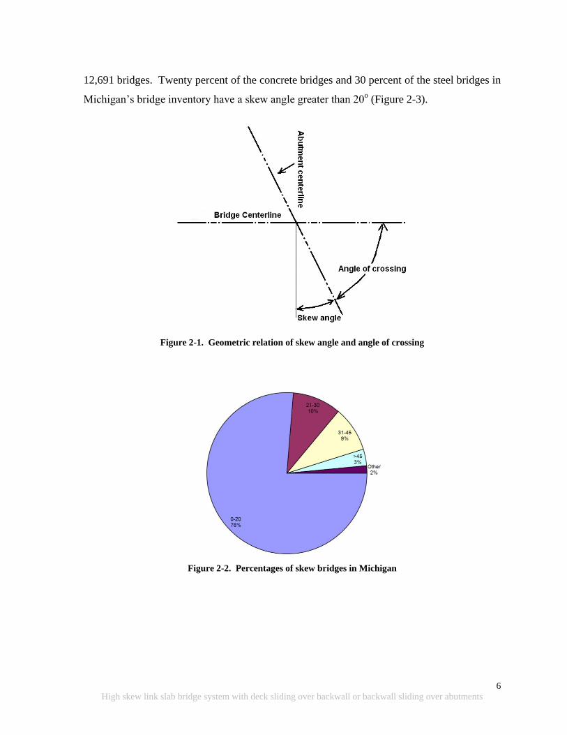
Figure 2-1. Geometric relation of skew angle and angle of crossing ...................................... 6
Figure 2-2. Percentages of skew bridges in Michigan ............................................................. 6
Figure 2-3. Percentage of skewed bridges in Michigan (a) concrete and (b) steel .................. 7
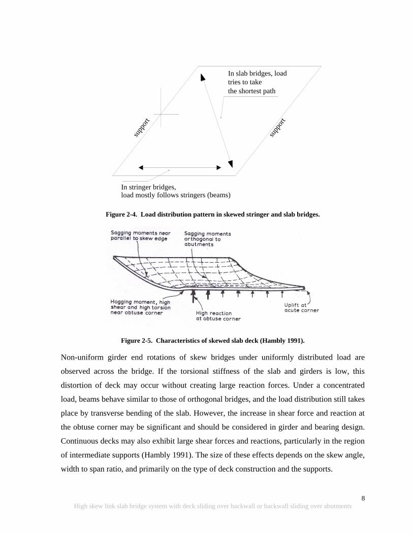
Figure 2-4. Load distribution pattern in skewed stringer and slab bridges. ............................. 8
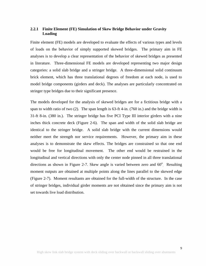
Figure 2-5. Characteristics of skewed slab deck (Hambly 1991). ........................................... 8
Figure 2-6. (a) Cross section and (b) isometric views of the stringer models ....................... 10
Figure 2-7. Plan view of FE models ...................................................................................... 10
Figure 2-8. Transverse bending stress distribution of deck for (a) stringer bridge deck and (b)
solid slab for 40o skew under self-weight .......................................................... 12
Figure 2-9. Longitudinal bending stress distribution (a) stringer (b) solid slab bridge of 40o
skew under self-weight (negative moment regions only) .................................. 12
Figure 2-10. Longitudinal bending moment variation against skew for full-width stringer
bridge under self-weight .................................................................................... 13
Figure 2-11. Longitudinal bending moment variation against skew for full-width stringer
bridge under a concentrated load ....................................................................... 13
Figure 2-12. Mid-span moment variation vs. skew angle under self-weight and concentrated
load for stringer bridge ....................................................................................... 14
Figure 2-13. Torsion for full-width of stringer bridge under self-weight .............................. 14
Figure 2-14. Torsion for full-width of stringer bridge under concentrated load ................... 15
Figure 2-15. Support reaction vs. skew angle for stringer bridge under self-weight ............. 15
Figure 2-16. Direction of skew simply supported bridge movement under uniform thermal
load ..................................................................................................................... 16
Figure 2-17. Bearing orientation for constraint cases (a) traditional, (b) radial from corner,
(c) radial from center (Tindal and Yoo 2003) .................................................... 17
Figure 2-18. Longitudinal displacement profile of deck for right and 45o skew bridge ........ 19
Figure 2-19. Transverse displacement profile of deck for right and 45o skew bridge ........... 20
Figure 2-20. Maximum normalized longitudinal and transverse displacement vs. skew angle
............................................................................................................................ 20
Figure 2-21. Forces on deck due to resistance encountered in expansion joints ................... 21
xxvi
High skew link slab bridge system with deck sliding over backwall or backwall sliding over abutments
Figure 2-22. Positive and negative temperature gradient loads used in the analyses ............ 22
Figure 2-23. Displacement contours under the traditional bearing condition for skew angles
............................................................................................................................ 23
Figure 2-24. Displacement contours under radial from corner bearing condition for skew
angles ................................................................................................................. 24
Figure 2-25. Displacement contours under the radial from center bearing condition for skew
angles ................................................................................................................. 25
Figure 2-26. Deformed shape under the traditional bearing condition for skew angles ........ 26
Figure 2-27. Deformed shape under radial from corner bearing condition for skew angles . 27
Figure 2-28. Deformed shape under radial from center bearing condition for skew angles . 28
Figure 2-29. Transverse (left) and longitudinal (right) displacement contours under the
traditional bearing condition for skew angles (a) 0° (b) 15° (c) 30° (d) 45° (e)
60° ...................................................................................................................... 30
Figure 2-30. Transverse (left) and longitudinal (right) displacement under the radial from
corner bearing condition for skew angles (a) 0° (b) 15° (c) 30° (d) 45° (e)
60° ...................................................................................................................... 31
Figure 2-31. Transverse (left) and longitudinal (right) displacement under the radial from
center bearing condition for skew angles (a) 0° (b) 15° (c) 30° (d) 45° (e) 60°
............................................................................................................................ 32
Figure 2-32. Longitudinal bending moment for full-width of simply supported stringer
bridge under negative temperature gradient ...................................................... 33
Figure 2-33. Torsion for full-width of simply supported stringer bridge under negative
temperature gradient .......................................................................................... 33
Figure 2-34. Percent of states that account for different forces in the design of jointless
bridges ................................................................................................................ 35
Figure 2-35. Resultant force components that develop at the abutment under thermal
expansion (Oesterle et al. 1999) ......................................................................... 36
Figure 2-36. Forces on the bridge (Steinberg et al. 2004) ..................................................... 37
Figure 2-37. Deformed shape of the deck of a two-span continuous skew stringer bridge
under uniform expansion ................................................................................... 38
Figure 2-38. Rub plate detail (VDOT) ................................................................................... 39
xxvii
High skew link slab bridge system with deck sliding over backwall or backwall sliding over abutments
Figure 2-39. VDOT deck extension detail with buried approach slab .................................. 40
Figure 2-40. Semi-integral abutment detail with end diaphragm moving over a fixed
abutment ............................................................................................................. 41
Figure 2-41. Semi-integral abutment details of concrete girder bridge with overall span <
328 ft .................................................................................................................. 42
Figure 2-42. Semi-integral abutment details of concrete girder bridge with overall span >
328 ft .................................................................................................................. 43
Figure 2-43. Semi-integral abutment details of steel girder bridge with overall span < 328 ft
............................................................................................................................ 44
Figure 2-44. Semi-integral abutment details of steel girder bridge with overall span > 328 ft
............................................................................................................................ 44
Figure 2-45. VDOT semi-integral system with EPS (Hoppe 2005) ...................................... 46
Figure 2-46. Typical details of EPS abutment (Stark et al. 2004) ......................................... 48
Figure 2-47. Deck sliding over backwall: (a) NYDOT and (b) MDOT ................................ 49
Figure 2-48. Preliminary bearing selection diagram for minimal design rotation (rotation ≤
0.005 radians) (source: Roeder and Stanton 1996) ............................................ 51
Figure 2-49. Preliminary bearing selection diagram for moderate design rotation (rotation ≤
0.015 radians) (source: Roeder and Stanton 1996) ............................................ 51
Figure 2-50. Preliminary bearing selection diagram for large design rotation (rotation >
0.015 radians) (source: Roeder and Stanton 1996) ............................................ 52
Figure 2-51. Preliminary bearing selection diagram (Badie, et al. 2001) .............................. 52
Figure 2-52. MDOT semi-integral abutment configuration .................................................. 53
Figure 2-53. Backwall and abutment configuration of a bridge with different girder depths 54
Figure 2-54. Reinforcement layout (AASHTO LRFD 2007) ................................................ 54
Figure 2-55. End zone reinforcement details (MDOT Bridge Design Guide 6.41.02) ......... 56
Figure 2-56. Link slab cracking on S08 of 63101 (Gilani and Jansson 2004)....................... 57
Figure 2-57. Link slab design detail and an inspection photo (Gilani and Jansson 2004) .... 58
Figure 2-58. Abutment wall cracking near an acute corner of the superstructure ................. 59
Figure 2-59. Semi-integral abutment configuration used by the Ontario MOT before most
recent details ...................................................................................................... 60
Figure 3-1. Bridge location (Source: Google map) ............................................................... 64
xxviii
High skew link slab bridge system with deck sliding over backwall or backwall sliding over abutments
Figure 3-2. Arial view of the bridge (Source: Google map) .................................................. 64
Figure 3-3. Isometric and elevation views of the bridge ....................................................... 65
Figure 3-4. Schematic view of bridge cross section .............................................................. 65
Figure 3-5. Schematic view of diaphragms and girders with labels ...................................... 66
Figure 3-6. Schematic view of end and intermediate diaphragms (cross frames) ................. 66
Figure 3-7. Schematic view of abutment section with backwall, girder and foundation ....... 67
Figure 3-8. Schematic view of girder plan and elevation ...................................................... 68
Figure 3-9. Schematic view of respective bearing details ..................................................... 69
Figure 3-10. Interior and exterior bearing condition at north abutment ................................ 70
Figure 3-11. Expansion bearing and joint condition at south abutment ................................ 70
Figure 3-12. Expansion bearing condition at south abutment ............................................... 71
Figure 3-13. Expansion joint and deck condition .................................................................. 72
Figure 3-14. FE model configuration..................................................................................... 73
Figure 3-15. Truck configuration and wheel loads ................................................................ 74
Figure 3-16. Truck positions and bridge configuration ......................................................... 75
Figure 3-17. Mutually exclusive bridge loading configurations ............................................ 75
Figure 3-18. Girder labels and 16 displacement measurement points ................................... 76
Figure 3-19. Girder bottom flange out of plane deformation, girder end translations, and
vertical deflection contours under loading configuration-I ............................... 76
Figure 3-20. Girder bottom flange out of plane deformation, girder end translations, and
vertical deflection contours under loading configuration-II .............................. 77
Figure 3-21. Girder bottom flange out of plane deformation, girder end translations, and
vertical deflection contours under loading configuration-III ............................. 77
Figure 3-22. Girder bottom flange out of plane deformation, girder end translations, and
vertical deflection contours under loading configuration-IV ............................. 78
Figure 3-23. Laser Tracker .................................................................................................... 79
Figure 3-24. Reflectors (targets) used with the Laser Tracker .............................................. 80
Figure 3-25. AT MeteoStation ............................................................................................... 80
Figure 3-26. Graphical user interface (GUI) window ............................................................ 80
Figure 3-27. Accessories used for mounting girder end and abutment targets ...................... 82
Figure 3-28. Laser Tracker, server, and computer ................................................................. 83
xxix
High skew link slab bridge system with deck sliding over backwall or backwall sliding over abutments
Figure 3-29. South abutment of the westbound bridge (targets on abutment and girder ends)
............................................................................................................................ 84
Figure 3-30. North abutment of the westbound bridge (targets on abutment and girder ends)
............................................................................................................................ 84
Figure 3-31. Target positions on girders ................................................................................ 85
Figure 3-32. Coordinate system for Tracker measurements and target positions on north
abutment and girder ends ................................................................................... 85
Figure 3-33. Truck configurations and wheel loads .............................................................. 87
Figure 3-34. Truck positions and bridge configuration ......................................................... 87
Figure 3-35. Mutually exclusive bridge loading configurations ............................................ 88
Figure 3-36. Girder A deflection under loading configuration II .......................................... 89
Figure 3-37. Girder G deflection under loading configuration IV ......................................... 89
Figure 3-38. Bearing movement under truck loads (FE analysis) ......................................... 90
Figure 3-39. 3-D view of bearing movement (towards south abutment) under loading
configuration IV ................................................................................................. 91
Figure 3-40. Bearing movement under truck loads (Tracker measurements) ....................... 92
Figure 3-41. Bearing positions after loading and unloading following load configuration II
and IV................................................................................................................. 92
Figure 3-42. Bearing translation under uniform thermal loads (FE analysis) ....................... 94
Figure 3-43. Maximum and minimum daily temperature variation at the site ...................... 95
Figure 3-44. Average temperature variation at the site .......................................................... 96
Figure 3-45. Bearing translation from Dec. 2010 to May 2011 and July 2011 (Tracker
measurements) ................................................................................................... 97
Figure 4-1. Cross section of Bridge S12-7 of 25042 ........................................................... 101
Figure 4-2. Current MDOT requirements for two-lane highway bridges ............................ 102
Figure 4-3. MDOT New Jersey Type 4 barriers .................................................................. 103
Figure 4-4. Cross section of bridge ...................................................................................... 103
Figure 4-5. Elevation view of FE bridge ............................................................................. 104
Figure 4-6. Bridge model orientation and labeling system .................................................. 104
Figure 4-7. Cross section view of single girder and deck .................................................... 106
Figure 4-8. Elevation view of mesh at link slab region ....................................................... 106

xxx
High skew link slab bridge system with deck sliding over backwall or backwall sliding over abutments
Figure 4-9. Isometric view of bridge models ....................................................................... 107
Figure 4-10. Skew link slab mesh ........................................................................................ 108
Figure 4-11. Contact surfaces in the FE models .................................................................. 109
Figure 4-12. Abaqus syntax used in FE bridge model ......................................................... 109
Figure 4-13. Bearing configuration layout ........................................................................... 110
Figure 4-14. Live load cases ................................................................................................ 111
Figure 4-15. Truck and lane load locations ......................................................................... 112
Figure 4-16. Temperature gradient ...................................................................................... 113
Figure 4-17. Sign convention ............................................................................................... 115
Figure 4-18. Total sectional moment - Lane1 load case ...................................................... 118
Figure 4-19. Total sectional moment - Lane2 load case ...................................................... 119
Figure 4-20. Total sectional moment – LaneAlt1 load case ................................................ 120
Figure 4-21. Total sectional moment – LaneAlt2 load case ................................................ 121
Figure 4-22. Total sectional moment - NTG load case ........................................................ 122
Figure 4-23. Total sectional moment - PTG load case ........................................................ 123
Figure 4-24. Total sectional force - Lane1 load case ........................................................... 124
Figure 4-25. Total sectional force - Lane2 load case ........................................................... 125
Figure 4-26. Total sectional force – LaneAlt1 load case ..................................................... 126
Figure 4-27. Total sectional force – LaneAlt2 load case ..................................................... 127
Figure 4-28. Total sectional force - NTG load case ............................................................. 128
Figure 4-29. Total sectional force - PTG load case ............................................................. 129
Figure 4-30. Effective width segments ................................................................................ 132
Figure 4-31. Effective moment - Lane1 load case ............................................................... 133
Figure 4-32. Effective moment - Lane2 load case ............................................................... 134
Figure 4-33. Effective moment – LaneAlt1 load case ......................................................... 135
Figure 4-34. Effective moment – LaneAlt2 load case ......................................................... 136
Figure 4-35. Effective moment - NTG load case ................................................................. 137
Figure 4-36. Effective moment - PTG load case ................................................................. 138
Figure 4-37. Effective force - Lane1 load case .................................................................... 139
Figure 4-38. Effective force - Lane2 load case .................................................................... 140
Figure 4-39. Effective Force – LaneAlt1 load case ............................................................. 141

xxxi
High skew link slab bridge system with deck sliding over backwall or backwall sliding over abutments
Figure 4-40. Effective Force – LaneAlt2 load case ............................................................. 142
Figure 4-41. Effective force - NTG load case ...................................................................... 143
Figure 4-42. Effective force - PTG load case ...................................................................... 144
Figure 4-43. Edge stresses of link slab with HRRR support conditions under live loads ... 147
Figure 4-44. Edge stresses of link slab with RRHR support conditions under live loads ... 148
Figure 4-45. Edge stresses of a 450 skew link slab under PTG ........................................... 149
Figure 4-46. Stresses developed in 450 skew link slab with HRRR support conditions under
LaneAlt1 load case ........................................................................................... 151
Figure 4-47. Gross section moment with and without soft material – LaneAlt1 load case . 152
Figure 4-48. Edge stresses developed under PTG - 450 skew link slab with soft material over
girder ends ........................................................................................................ 154
Figure 4-49. Link slab bottom fiber stresses under PTG load ............................................. 155
Figure 4-50. Longitudinal stress distribution across north end of the 450 skew link slab
bottom fiber under PTG with HRRR support configuration ........................... 156
Figure 4-51. Longitudinal stress distribution across south end of the 450 skew link slab
bottom fiber under PTG with RRHR support configuration ........................... 156
Figure 4-52. Stresses in link slab with HRRR under PTG .................................................. 157
Figure 4-53. AASHTO Type III girder and composite section geometric properties ......... 164
Figure 5-1. Deck sliding over backwall details ................................................................... 170
Figure 5-2. Semi-integral abutment details .......................................................................... 171
Figure 5-3. Semi-integral abutment detail used in Ontario and several other states ........... 172
Figure 5-4. Rub plates at backwall - wingwall interface (Source: VDOT 2010) ................ 173
Figure 5-5. Rub plates at deck-wingwall interface (Source: VDOT 2010) ......................... 173
Figure 5-6. Bearing retainer detail (Source: Steinberg and Sargand 2010; Roeder and Stanton
1996) ................................................................................................................ 174
Figure 5-7. Dowel bar details for resisting lateral loads on shallow bearing (Source: Roeder
and Stanton 1996). ........................................................................................... 174
Figure 5-8. Concrete key system for resisting lateral forces (Source: Roeder and Stanton
1996). ............................................................................................................... 174
Figure 5-9. Live load configuration for CASE IV Contraction ............................................ 177
Figure 5-10. Live load configuration for CASE IV Expansion ............................................ 178

xxxii
High skew link slab bridge system with deck sliding over backwall or backwall sliding over abutments
Figure 5-11. Location of girder 1 and 8 where girder end rotation was calculated ............. 179
Figure 5-12. Truck position 1 for girder end rotation calculation ....................................... 180
Figure 5-13. Truck position 2 for girder end rotation calculation ....................................... 180
Figure 5-14. Truck position 3 for girder end rotation calculation ....................................... 181
Figure 5-15. Deck sliding over backwall model description ............................................... 184
Figure 5-16. Abutment and girder end distress .................................................................... 186
Figure 5-17. Girder 1 and 8 end rotation over abutment ..................................................... 187
Figure 5-18. Thermal expansion of a skew bridge .............................................................. 190
Figure 5-19. Maximum longitudinal bridge contraction and expansion ............................... 190
Figure 5-20. Variation of concrete bridge expansion length against width and skew when
strip seal joint width of 3 in. available for thermal movement ........................ 191
Figure 5-21. Variation of steel girder bridge expansion against width and skew when strip
seal joint width of 3 in. available for thermal movement ................................ 191
Figure 5-22. Girder 1 and 8 reaction variation over the abutment and pier ......................... 193
Figure 5-23. Transverse bearing force over abutment under thermal contraction strength load
combination...................................................................................................... 196
Figure 5-24. Transverse bearing force over abutment under thermal expansion strength load
combination...................................................................................................... 197
Figure 5-25. Typical bearing details .................................................................................... 198
Figure 5-26. Semi-integral bridge model with wingwalls (not drawn to scale) .................. 199
Figure 5-27. Girder 1 ration of semi-integral bridge ........................................................... 200
Figure 5-28. Transverse bearing force over abutment under thermal contraction strength load
combination...................................................................................................... 203
Figure 5-29. Transverse bearing force over abutment under thermal expansion strength load
combination...................................................................................................... 204
Figure 5-30. Wingwall force due to thermal expansion without transverse restraint over the
abutment under strength load combination ...................................................... 204
1
High skew link slab bridge system with deck sliding over backwall or backwall sliding over abutments
1 INTRODUCTION
1.1 OVERVIEW
High skew link slab design and design details are described in this report. Abutment and
bearing redesign is also described for implementing link slabs on existing high skew bridges
during repair activities.
A new bridge design and construction trend to help improve durability and rideability is to
remove expansion joints over piers and abutments. One approach to achieve this is to make
the deck continuous over the piers by means of a link slab while the girders remain simply
supported. The need to implement link slabs is indicated by AASHTO LRFD (2010) section
2.5.2.4 that stipulates the use of minimum number of expansion joints to improve rideability.
Further, due to durability concerns associated with bridge deck joints, as stated in Aktan et al.
(2002), it is preferred to have as few joints as possible or to develop jointless decks.
In most unremarkable bridges, expansion joints over the abutments can be removed during
repair activities. The deck and approach slab can be made continuous based on one of three
designs: deck sliding over backwall, semi-integral abutments, and integral abutments. These
designs will develop expansion joints at either or both ends of the approaches. Link slabs can
be incorporated in repair activities such as partial deck replacement and shallow or deep
overlay projects. In the case of full deck replacement, bearings can also be redesigned to
allow for the desired movement. The design concerns, other than link slab, include backwall,
wing-wall, and bearings. The behavior of jointless bridges brings about many challenges to
bridge designers. The complexity is augmented when skew is involved.
The skew policy described in section 7.01.14 of the MDOT Bridge Design Manual (2005),
requires special design by refined analysis methods for bridges with skew greater than 300
but less than or equal to 450. Further, for skew greater than 45
0, special approval through
bridge design is required. These requirements reflect the complexity of the structure when
the skew is involved.
2
High skew link slab bridge system with deck sliding over backwall or backwall sliding over abutments
This report complements an earlier report on Combining Link Slab, Deck Sliding Over
Backwall and Revising Bearings (Aktan et al. 2008) where the behavior of straight and
moderately skew (skew 200) link slab bridges were investigated, and design
recommendations were developed. This report will describe the behavior and performance
of high skew (skew > 200) jointless bridges with link slabs and two abutment configurations.
These abutment configurations are deck sliding over backwall and backwall sliding over
abutments (semi-integral abutments). This report is intended to be a tool to the designers in
the design of specific components and design detail recommendations that are intended to
improve the durability performance of high skew bridges constructed with the link slabs and
deck sliding over backwall or backwall sliding over the abutments.
1.2 PROJECT OBJECTIVES AND TASKS
The objective of this project was to assess the performance and behavior of a high skew
bridge structural system with link slabs and sliding deck over backwall or backwall sliding
over abutment (semi-integral). The high skew bridge assessment was based on literature
review, load testing, and analytical modeling and analysis. The project goal was to propose
fine-tuning of the design assumptions and design details for the link slab and the abutment
region.
The project tasks were as follows: (1) literature review, (2) assessment of skew bridge
behavior under static truck loads and thermal expansion, (3) analytical and numerical
analysis of skew link slabs, and (4) analytical and numerical analysis of skew sliding deck
over backwall systems and semi-integral abutments.
1.3 REPORT ORGANIZATION
The report is organized with 7 chapters.
The Literature Review is presented in chapter 2 describing skew/jointless bridge
behavior, modeling and analysis of skew bridge structural system/components, design
and detailing of deck sliding over backwall and semi-integral abutments, and
performance of jointless bridges.

3
High skew link slab bridge system with deck sliding over backwall or backwall sliding over abutments
High skew bridge assessment under truck loads and thermal loads is presented in
chapter 3.
Chapter 4 describes skew link slab analysis and design.
Chapter 5 describes skew abutment analysis and design.
Chapter 6 presents the comprehensive results, recommendations, the need for further
work, and
Chapter 7 lists the references.

4
High skew link slab bridge system with deck sliding over backwall or backwall sliding over abutments
Intentionally left blank

5
High skew link slab bridge system with deck sliding over backwall or backwall sliding over abutments
2 STATE-OF-THE-ART LITERATURE REVIEW
The objective of the literature review was to identify, review, and synthesize information
related to skewed/jointless bridges. Finite element modeling of simply supported skewed
bridges is also incorporated in various sections of the chapter to compare with and/or to
benchmark the pertinent information available in literature. Concentration areas for the
review are established for the project, and the following aspects will be discussed:
Skewed bridge behavior under gravity loading,
Skewed bridge behavior under volume change loads,
Design challenges of skewed/jointless bridges, and
Performance of skew/ jointless bridges.
2.1 OVERVIEW
A skewed bridge is one in which the major axis of the substructure is not perpendicular to the
longitudinal axis of the superstructure. The skew angle (most commonly in degrees) is
defined as the angle between the axis normal to the bridge centerline and the axis along the
abutment or pier cap centerline. Some highway agencies use a different convention. As an
example, Michigan uses the angle of crossing which is the acute (small) angle formed
between the longitudinal bridge axis and the abutment or pier cap centerline axis (Figure
2-1).
The majority of bridge decks built today have some form of skew, taper or curve. Because of
the increasing restriction on available space for traffic schemes, the alignment of a
transportation system can seldom be adjusted to reduce the skew. A skew angle greater than
200 alters the bending moment and shear developed in a bridge compared to those of a
straight bridge. Skew bridge decks are prone to develop deck corner cracking (Fu et al.
2007).
About two-thirds of bridges nationwide are skewed (AASHTO LRFD 2010). According to
the Pontis database, as of 2006, there are about 2,800 bridges in Michigan with a skew angle
greater than 20o (Figure 2-2). This is in excess of 20 percent of the total bridge population of
6
High skew link slab bridge system with deck sliding over backwall or backwall sliding over abutments
12,691 bridges. Twenty percent of the concrete bridges and 30 percent of the steel bridges in
Michigan‟s bridge inventory have a skew angle greater than 20o (Figure 2-3).
Figure 2-1. Geometric relation of skew angle and angle of crossing
Figure 2-2. Percentages of skew bridges in Michigan

7
High skew link slab bridge system with deck sliding over backwall or backwall sliding over abutments
(a)
(b)
Figure 2-3. Percentage of skewed bridges in Michigan (a) concrete and (b) steel
2.2 SKEWED BRIDGE BEHAVIOR UNDER GRAVITY LOADING
In slab bridges and other bridges with high torsional rigidity, the load path develops between
the obtuse (>90o) corners of the span (Figure 2-4). Longitudinal bending moments are
reduced, but shear forces are increased in the obtuse corners (Figure 2-5). The special
characteristics of the load response characteristics of a skewed solid slab bridge are
summarized in Hambly (1991) as follows:
1. Variation in direction of calculated maximum bending moment across bridge width
(Figure 2-5),
2. Hogging (negative) moments near obtuse (>90o) corner,
3. Torsion developing on the deck,
4. Larger reactions and shear forces near obtuse corner, and
5. Lower reactions and possible uplift in acute (<90o) corner.
The effects described above may also occur in stringer bridges, but they are much less
pronounced. In stringer bridges, such as I- Tee- or bulb-tee beam bridges, the load tends to
flow along the length of the supporting beams, and the effect of skew on the bending
moments is reduced (Figure 2-4).
8
High skew link slab bridge system with deck sliding over backwall or backwall sliding over abutments
supp
ort
supp
ort
In stringer bridges,load mostly follows stringers (beams)
In slab bridges, load
tries to take
the shortest path
Figure 2-4. Load distribution pattern in skewed stringer and slab bridges.
Figure 2-5. Characteristics of skewed slab deck (Hambly 1991).
Non-uniform girder end rotations of skew bridges under uniformly distributed load are
observed across the bridge. If the torsional stiffness of the slab and girders is low, this
distortion of deck may occur without creating large reaction forces. Under a concentrated
load, beams behave similar to those of orthogonal bridges, and the load distribution still takes
place by transverse bending of the slab. However, the increase in shear force and reaction at
the obtuse corner may be significant and should be considered in girder and bearing design.
Continuous decks may also exhibit large shear forces and reactions, particularly in the region
of intermediate supports (Hambly 1991). The size of these effects depends on the skew angle,
width to span ratio, and primarily on the type of deck construction and the supports.
9
High skew link slab bridge system with deck sliding over backwall or backwall sliding over abutments
2.2.1 Finite Element (FE) Simulation of Skew Bridge Behavior under Gravity
Loading
Finite element (FE) models are developed to evaluate the effects of various types and levels
of loads on the behavior of simply supported skewed bridges. The primary aim in FE
analyses is to develop a clear representation of the behavior of skewed bridges as presented
in literature. Three-dimensional FE models are developed representing two major design
categories: a solid slab bridge and a stringer bridge. A three-dimensional solid continuum
brick element, which has three translational degrees of freedom at each node, is used to
model bridge components (girders and deck). The analyses are particularly concentrated on
stringer type bridges due to their significant presence.
The models developed for the analysis of skewed bridges are for a fictitious bridge with a
span to width ratio of two (2). The span length is 63-ft 4-in. (760 in.) and the bridge width is
31-ft 8-in. (380 in.). The stringer bridge has five PCI Type III interior girders with a nine
inches thick concrete deck (Figure 2-6). The span and width of the solid slab bridge are
identical to the stringer bridge. A solid slab bridge with the current dimensions would
neither meet the strength nor service requirements. However, the primary aim in these
analyses is to demonstrate the skew effects. The bridges are constrained so that one end
would be free for longitudinal movement. The other end would be restrained in the
longitudinal and vertical directions with only the center node pinned in all three translational
directions as shown in Figure 2-7. Skew angle is varied between zero and 60o
. Resulting
moment outputs are obtained at multiple points along the lines parallel to the skewed edge
(Figure 2-7). Moment resultants are obtained for the full-width of the structure. In the case
of stringer bridges, individual girder moments are not obtained since the primary aim is not
set towards live load distribution.
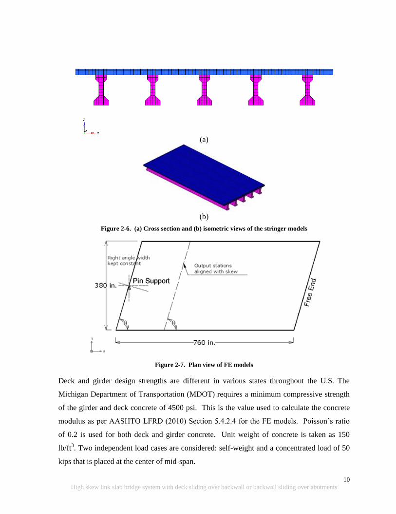
10
High skew link slab bridge system with deck sliding over backwall or backwall sliding over abutments
(a)
(b)
Figure 2-6. (a) Cross section and (b) isometric views of the stringer models
Figure 2-7. Plan view of FE models
Deck and girder design strengths are different in various states throughout the U.S. The
Michigan Department of Transportation (MDOT) requires a minimum compressive strength
of the girder and deck concrete of 4500 psi. This is the value used to calculate the concrete
modulus as per AASHTO LFRD (2010) Section 5.4.2.4 for the FE models. Poisson‟s ratio
of 0.2 is used for both deck and girder concrete. Unit weight of concrete is taken as 150
lb/ft3. Two independent load cases are considered: self-weight and a concentrated load of 50
kips that is placed at the center of mid-span.
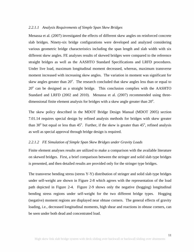
11
High skew link slab bridge system with deck sliding over backwall or backwall sliding over abutments
2.2.1.1 Analysis Requirements of Simple Span Skew Bridges
Menassa et al. (2007) investigated the effects of different skew angles on reinforced concrete
slab bridges. Ninety-six bridge configurations were developed and analyzed considering
various geometric bridge characteristics including the span length and slab width with six
different skew angles. FE analyses results of skewed bridges were compared to the reference
straight bridges as well as the AASHTO Standard Specifications and LRFD procedures.
Under live load, maximum longitudinal moment decreased, whereas, maximum transverse
moment increased with increasing skew angles. The variation in moment was significant for
skew angles greater than 20o. The research concluded that skew angles less than or equal to
20o can be designed as a straight bridge. This conclusion complies with the AASHTO
Standard and LRFD (2002 and 2010). Menassa et al. (2007) recommended using three-
dimensional finite element analysis for bridges with a skew angle greater than 20o.
The skew policy described in the MDOT Bridge Design Manual (MDOT 2005) section
7.01.14 requires special design by refined analysis methods for bridges with skew greater
than 30o but equal or less than 45
o. Further, if the skew is greater than 45
o, refined analysis
as well as special approval through bridge design is required.
2.2.1.2 FE Simulation of Simple Span Skew Bridges under Gravity Loads
Finite element analyses results are utilized to make a comparison with the available literature
on skewed bridges. First, a brief comparison between the stringer and solid slab type bridges
is presented, and then detailed results are provided only for the stringer type bridges.
The transverse bending stress (stress Y-Y) distribution of stringer and solid slab type bridges
under self-weight are shown in Figure 2-8 which agrees with the representation of the load
path depicted in Figure 2-4. Figure 2-9 shows only the negative (hogging) longitudinal
bending stress regions under self-weight for the two different bridge types. Hogging
(negative) moment regions are displayed near obtuse corners. The general effects of gravity
loading, i.e., decreased longitudinal moments, high shear and reactions in obtuse corners, can
be seen under both dead and concentrated load.
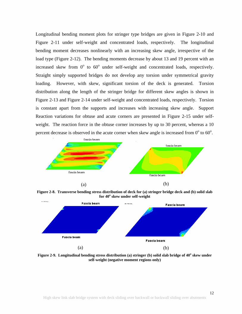
12
High skew link slab bridge system with deck sliding over backwall or backwall sliding over abutments
Longitudinal bending moment plots for stringer type bridges are given in Figure 2-10 and
Figure 2-11 under self-weight and concentrated loads, respectively. The longitudinal
bending moment decreases nonlinearly with an increasing skew angle, irrespective of the
load type (Figure 2-12). The bending moments decrease by about 13 and 19 percent with an
increased skew from 0o to 60
o under self-weight and concentrated loads, respectively.
Straight simply supported bridges do not develop any torsion under symmetrical gravity
loading. However, with skew, significant torsion of the deck is generated. Torsion
distribution along the length of the stringer bridge for different skew angles is shown in
Figure 2-13 and Figure 2-14 under self-weight and concentrated loads, respectively. Torsion
is constant apart from the supports and increases with increasing skew angle. Support
Reaction variations for obtuse and acute corners are presented in Figure 2-15 under self-
weight. The reaction force in the obtuse corner increases by up to 30 percent, whereas a 10
percent decrease is observed in the acute corner when skew angle is increased from 0o to 60
o.
(a)
(b)
Figure 2-8. Transverse bending stress distribution of deck for (a) stringer bridge deck and (b) solid slab
for 40o skew under self-weight
(a)
(b)
Figure 2-9. Longitudinal bending stress distribution (a) stringer (b) solid slab bridge of 40o skew under
self-weight (negative moment regions only)
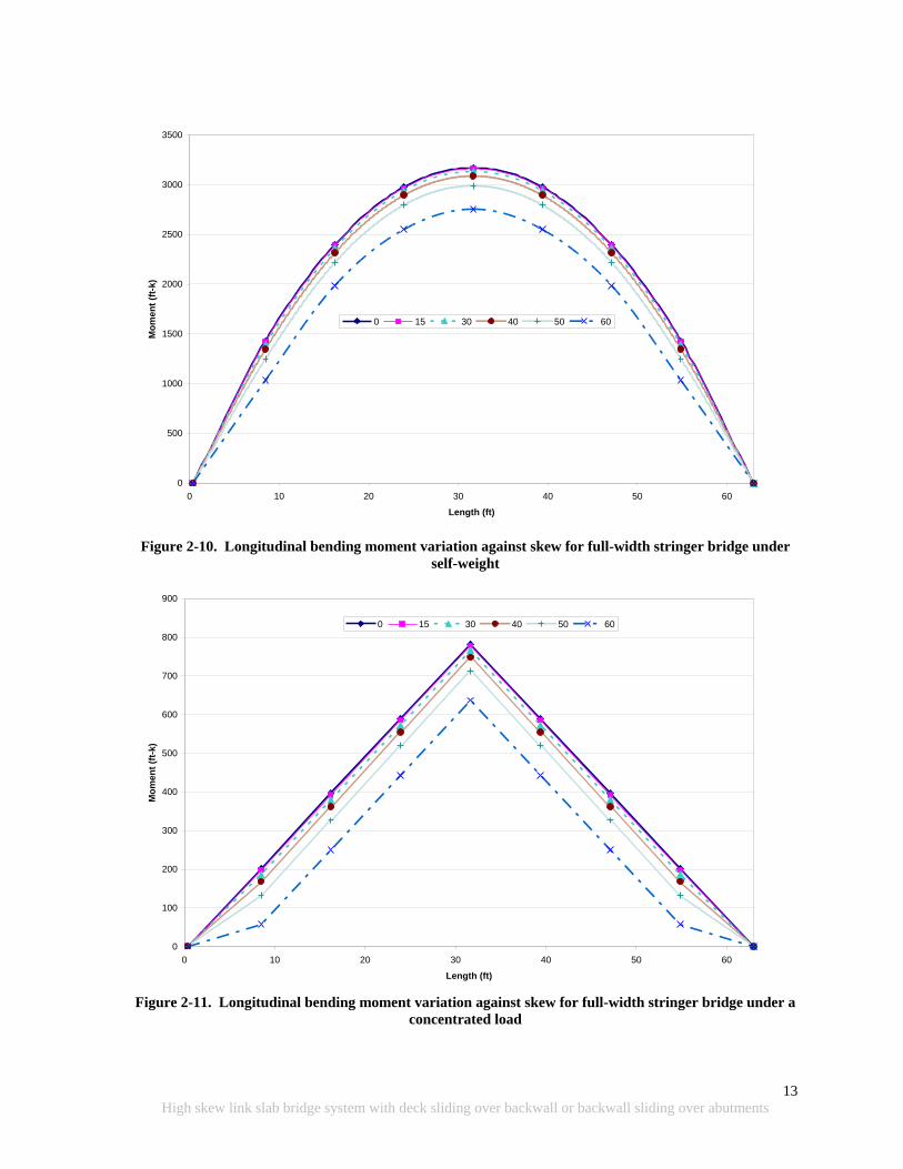
13
High skew link slab bridge system with deck sliding over backwall or backwall sliding over abutments
Figure 2-10. Longitudinal bending moment variation against skew for full-width stringer bridge under
self-weight
Figure 2-11. Longitudinal bending moment variation against skew for full-width stringer bridge under a
concentrated load
0
500
1000
1500
2000
2500
3000
3500
0 10 20 30 40 50 60
Length (ft)
Mo
men
t (f
t-k)
0 15 30 40 50 60
0
100
200
300
400
500
600
700
800
900
0 10 20 30 40 50 60
Length (ft)
Mo
men
t (f
t-k)
0 15 30 40 50 60
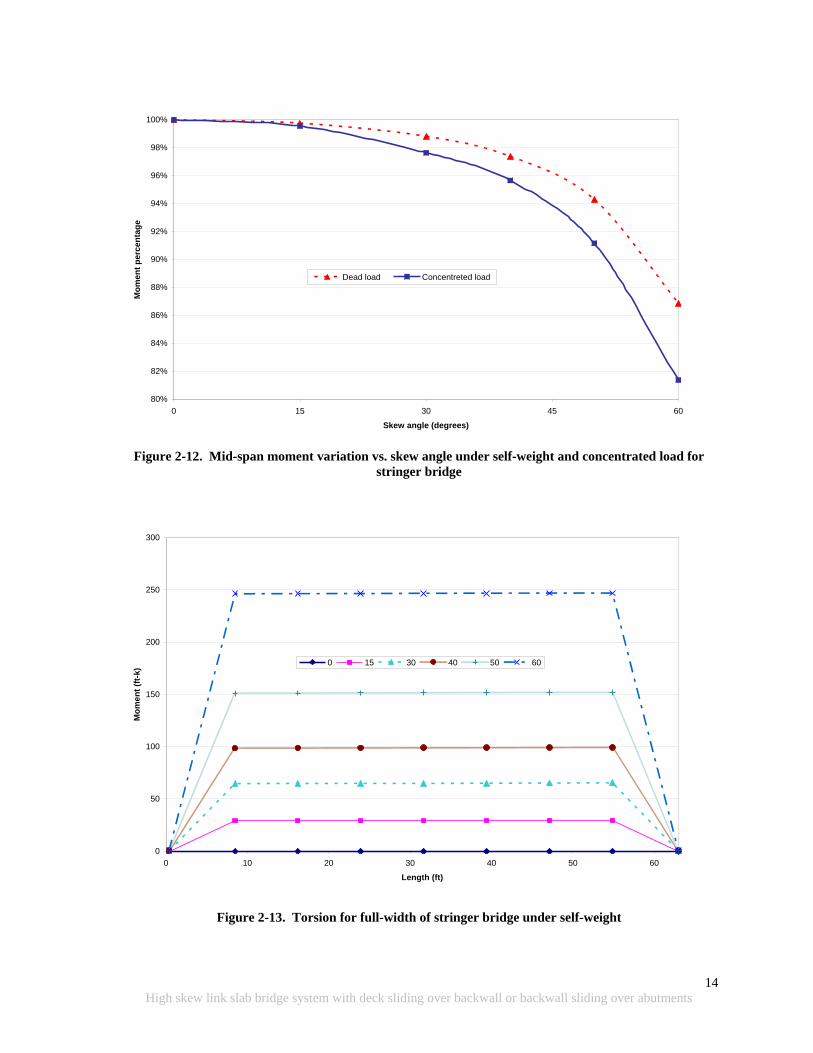
14
High skew link slab bridge system with deck sliding over backwall or backwall sliding over abutments
Figure 2-12. Mid-span moment variation vs. skew angle under self-weight and concentrated load for
stringer bridge
Figure 2-13. Torsion for full-width of stringer bridge under self-weight
Moment vs skew angle
80%
82%
84%
86%
88%
90%
92%
94%
96%
98%
100%
0 15 30 45 60
Skew angle (degrees)
Mo
me
nt
pe
rce
nta
ge
Dead load Concentreted load
0
50
100
150
200
250
300
0 10 20 30 40 50 60
Length (ft)
Mo
men
t (f
t-k)
0 15 30 40 50 60

15
High skew link slab bridge system with deck sliding over backwall or backwall sliding over abutments
Figure 2-14. Torsion for full-width of stringer bridge under concentrated load
Figure 2-15. Support reaction vs. skew angle for stringer bridge under self-weight
0
10
20
30
40
50
60
70
80
90
0 10 20 30 40 50 60
Length (ft)
Mo
men
t (f
t-k)
0 15 30 40 50 60
Skew Angle vs Reaction
80%
90%
100%
110%
120%
130%
140%
0 15 30 45 60
Skew (degrees)
Reacti
on
Perc
en
tag
e
Obtuse Corner Acute Corner

16
High skew link slab bridge system with deck sliding over backwall or backwall sliding over abutments
2.3 SKEWED BRIDGE BEHAVIOR UNDER VOLUME CHANGE LOADS
Skewed bridges exhibit a complex response pattern under volume change loads with regard
to both bearing deformations and restraint forces. Transverse movement is generated in wider
bridges that tend to rotate with respect to the vertical axis. Restraint forces vary considerably
with skew and show nonlinear behavior (Tindal and Yoo 2003). The direction of movement
and rotation of bearings for curved and high skew bridges depends on many factors and is not
easily determined. However, the major axis of thermal movement on a high skew bridge is
most generally along the diagonal between the acute corners (Figure 2-16). The alignments
of the bearings and layout of the keeper blocks parallel to the axis relieve all the stresses; yet
implementation is not very practical (AASHTO LRFD 2010).
Figure 2-16. Direction of skew simply supported bridge movement under uniform thermal load
Round bearings are recommended for curved and high skew bridges since they can
accommodate movement and rotations in multiple directions. Round bearings also require a
narrower bridge seat on skew bridges (Najm et al. 2007).
According to a survey conducted by Najm et al. (2007), eight out of 39 state DOTs (21%)
have used round bearings. Eighteen states (46%) were willing to consider using them.
Agencies have used round bearings on curved and high skew bridges, and on pier caps with
limited space. According to the survey results, 29% of the round bearing applications were
for mild skew bridges, 50% for high skew, and 21% for curved bridges. As for bridge length
and type, most of the bridges with round bearings have spans less than 115 ft long, and two-
thirds of these bridges were precast concrete girder bridges while the remaining were steel
stringer .
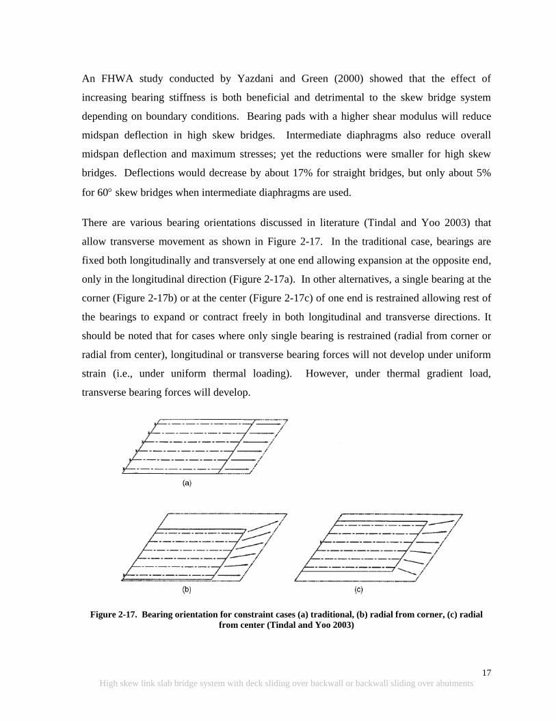
17
High skew link slab bridge system with deck sliding over backwall or backwall sliding over abutments
An FHWA study conducted by Yazdani and Green (2000) showed that the effect of
increasing bearing stiffness is both beneficial and detrimental to the skew bridge system
depending on boundary conditions. Bearing pads with a higher shear modulus will reduce
midspan deflection in high skew bridges. Intermediate diaphragms also reduce overall
midspan deflection and maximum stresses; yet the reductions were smaller for high skew
bridges. Deflections would decrease by about 17% for straight bridges, but only about 5%
for 60skew bridges when intermediate diaphragms are used.
There are various bearing orientations discussed in literature (Tindal and Yoo 2003) that
allow transverse movement as shown in Figure 2-17. In the traditional case, bearings are
fixed both longitudinally and transversely at one end allowing expansion at the opposite end,
only in the longitudinal direction (Figure 2-17a). In other alternatives, a single bearing at the
corner (Figure 2-17b) or at the center (Figure 2-17c) of one end is restrained allowing rest of
the bearings to expand or contract freely in both longitudinal and transverse directions. It
should be noted that for cases where only single bearing is restrained (radial from corner or
radial from center), longitudinal or transverse bearing forces will not develop under uniform
strain (i.e., under uniform thermal loading). However, under thermal gradient load,
transverse bearing forces will develop.
Figure 2-17. Bearing orientation for constraint cases (a) traditional, (b) radial from corner, (c) radial
from center (Tindal and Yoo 2003)
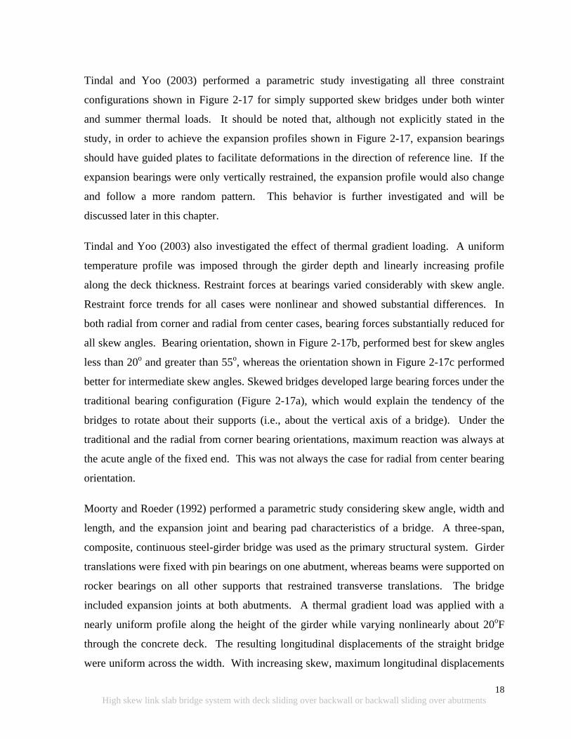
18
High skew link slab bridge system with deck sliding over backwall or backwall sliding over abutments
Tindal and Yoo (2003) performed a parametric study investigating all three constraint
configurations shown in Figure 2-17 for simply supported skew bridges under both winter
and summer thermal loads. It should be noted that, although not explicitly stated in the
study, in order to achieve the expansion profiles shown in Figure 2-17, expansion bearings
should have guided plates to facilitate deformations in the direction of reference line. If the
expansion bearings were only vertically restrained, the expansion profile would also change
and follow a more random pattern. This behavior is further investigated and will be
discussed later in this chapter.
Tindal and Yoo (2003) also investigated the effect of thermal gradient loading. A uniform
temperature profile was imposed through the girder depth and linearly increasing profile
along the deck thickness. Restraint forces at bearings varied considerably with skew angle.
Restraint force trends for all cases were nonlinear and showed substantial differences. In
both radial from corner and radial from center cases, bearing forces substantially reduced for
all skew angles. Bearing orientation, shown in Figure 2-17b, performed best for skew angles
less than 20o and greater than 55
o, whereas the orientation shown in Figure 2-17c performed
better for intermediate skew angles. Skewed bridges developed large bearing forces under the
traditional bearing configuration (Figure 2-17a), which would explain the tendency of the
bridges to rotate about their supports (i.e., about the vertical axis of a bridge). Under the
traditional and the radial from corner bearing orientations, maximum reaction was always at
the acute angle of the fixed end. This was not always the case for radial from center bearing
orientation.
Moorty and Roeder (1992) performed a parametric study considering skew angle, width and
length, and the expansion joint and bearing pad characteristics of a bridge. A three-span,
composite, continuous steel-girder bridge was used as the primary structural system. Girder
translations were fixed with pin bearings on one abutment, whereas beams were supported on
rocker bearings on all other supports that restrained transverse translations. The bridge
included expansion joints at both abutments. A thermal gradient load was applied with a
nearly uniform profile along the height of the girder while varying nonlinearly about 20oF
through the concrete deck. The resulting longitudinal displacements of the straight bridge
were uniform across the width. With increasing skew, maximum longitudinal displacements
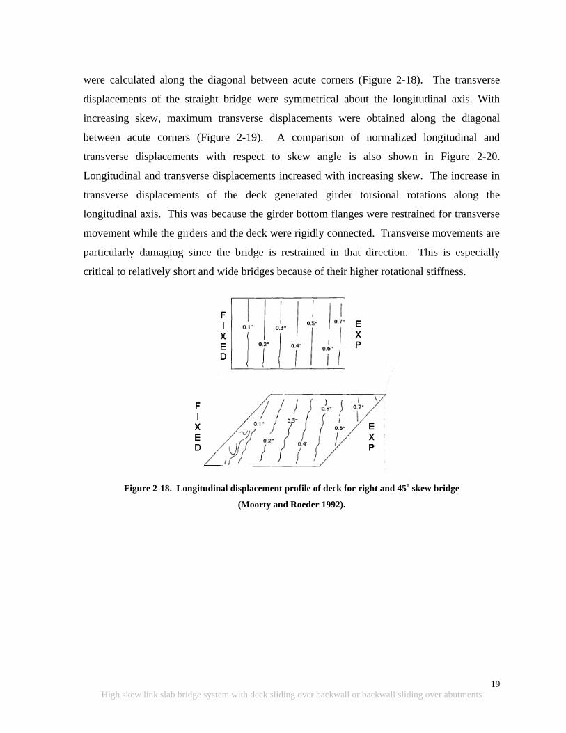
19
High skew link slab bridge system with deck sliding over backwall or backwall sliding over abutments
were calculated along the diagonal between acute corners (Figure 2-18). The transverse
displacements of the straight bridge were symmetrical about the longitudinal axis. With
increasing skew, maximum transverse displacements were obtained along the diagonal
between acute corners (Figure 2-19). A comparison of normalized longitudinal and
transverse displacements with respect to skew angle is also shown in Figure 2-20.
Longitudinal and transverse displacements increased with increasing skew. The increase in
transverse displacements of the deck generated girder torsional rotations along the
longitudinal axis. This was because the girder bottom flanges were restrained for transverse
movement while the girders and the deck were rigidly connected. Transverse movements are
particularly damaging since the bridge is restrained in that direction. This is especially
critical to relatively short and wide bridges because of their higher rotational stiffness.
Figure 2-18. Longitudinal displacement profile of deck for right and 45o skew bridge
(Moorty and Roeder 1992).
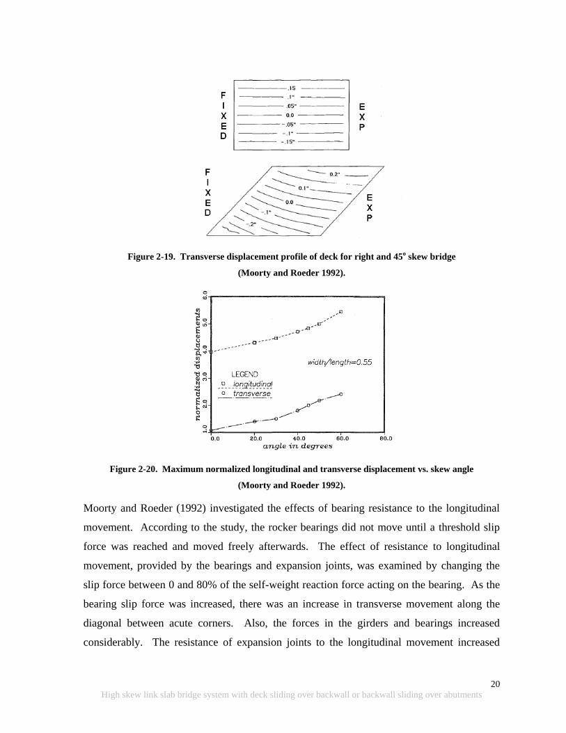
20
High skew link slab bridge system with deck sliding over backwall or backwall sliding over abutments
Figure 2-19. Transverse displacement profile of deck for right and 45o skew bridge
(Moorty and Roeder 1992).
Figure 2-20. Maximum normalized longitudinal and transverse displacement vs. skew angle
(Moorty and Roeder 1992).
Moorty and Roeder (1992) investigated the effects of bearing resistance to the longitudinal
movement. According to the study, the rocker bearings did not move until a threshold slip
force was reached and moved freely afterwards. The effect of resistance to longitudinal
movement, provided by the bearings and expansion joints, was examined by changing the
slip force between 0 and 80% of the self-weight reaction force acting on the bearing. As the
bearing slip force was increased, there was an increase in transverse movement along the
diagonal between acute corners. Also, the forces in the girders and bearings increased
considerably. The resistance of expansion joints to the longitudinal movement increased
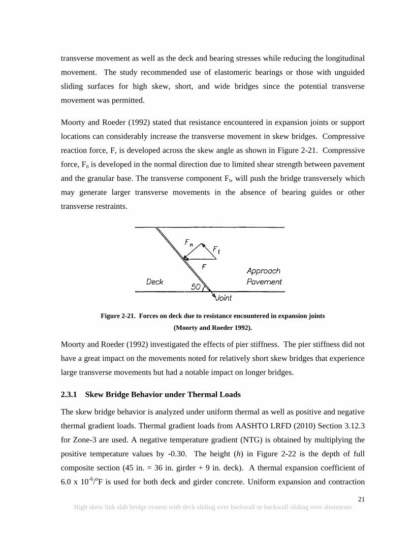
21
High skew link slab bridge system with deck sliding over backwall or backwall sliding over abutments
transverse movement as well as the deck and bearing stresses while reducing the longitudinal
movement. The study recommended use of elastomeric bearings or those with unguided
sliding surfaces for high skew, short, and wide bridges since the potential transverse
movement was permitted.
Moorty and Roeder (1992) stated that resistance encountered in expansion joints or support
locations can considerably increase the transverse movement in skew bridges. Compressive
reaction force, F, is developed across the skew angle as shown in Figure 2-21. Compressive
force, Fn is developed in the normal direction due to limited shear strength between pavement
and the granular base. The transverse component Ft, will push the bridge transversely which
may generate larger transverse movements in the absence of bearing guides or other
transverse restraints.
Figure 2-21. Forces on deck due to resistance encountered in expansion joints
(Moorty and Roeder 1992).
Moorty and Roeder (1992) investigated the effects of pier stiffness. The pier stiffness did not
have a great impact on the movements noted for relatively short skew bridges that experience
large transverse movements but had a notable impact on longer bridges.
2.3.1 Skew Bridge Behavior under Thermal Loads
The skew bridge behavior is analyzed under uniform thermal as well as positive and negative
thermal gradient loads. Thermal gradient loads from AASHTO LRFD (2010) Section 3.12.3
for Zone-3 are used. A negative temperature gradient (NTG) is obtained by multiplying the
positive temperature values by -0.30. The height (h) in Figure 2-22 is the depth of full
composite section (45 in. = 36 in. girder + 9 in. deck). A thermal expansion coefficient of
6.0 x 10⁻⁶
/oF is used for both deck and girder concrete. Uniform expansion and contraction
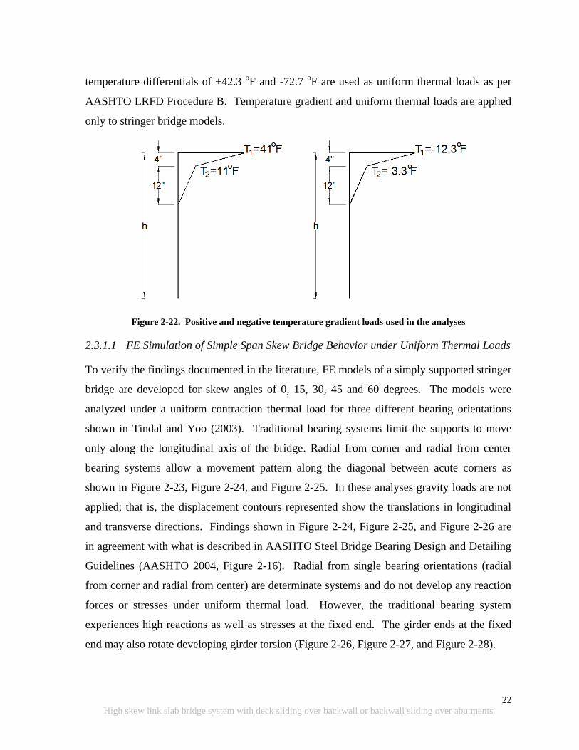
22
High skew link slab bridge system with deck sliding over backwall or backwall sliding over abutments
temperature differentials of +42.3 oF and -72.7
oF are used as uniform thermal loads as per
AASHTO LRFD Procedure B. Temperature gradient and uniform thermal loads are applied
only to stringer bridge models.
Figure 2-22. Positive and negative temperature gradient loads used in the analyses
2.3.1.1 FE Simulation of Simple Span Skew Bridge Behavior under Uniform Thermal Loads
To verify the findings documented in the literature, FE models of a simply supported stringer
bridge are developed for skew angles of 0, 15, 30, 45 and 60 degrees. The models were
analyzed under a uniform contraction thermal load for three different bearing orientations
shown in Tindal and Yoo (2003). Traditional bearing systems limit the supports to move
only along the longitudinal axis of the bridge. Radial from corner and radial from center
bearing systems allow a movement pattern along the diagonal between acute corners as
shown in Figure 2-23, Figure 2-24, and Figure 2-25. In these analyses gravity loads are not
applied; that is, the displacement contours represented show the translations in longitudinal
and transverse directions. Findings shown in Figure 2-24, Figure 2-25, and Figure 2-26 are
in agreement with what is described in AASHTO Steel Bridge Bearing Design and Detailing
Guidelines (AASHTO 2004, Figure 2-16). Radial from single bearing orientations (radial
from corner and radial from center) are determinate systems and do not develop any reaction
forces or stresses under uniform thermal load. However, the traditional bearing system
experiences high reactions as well as stresses at the fixed end. The girder ends at the fixed
end may also rotate developing girder torsion (Figure 2-26, Figure 2-27, and Figure 2-28).
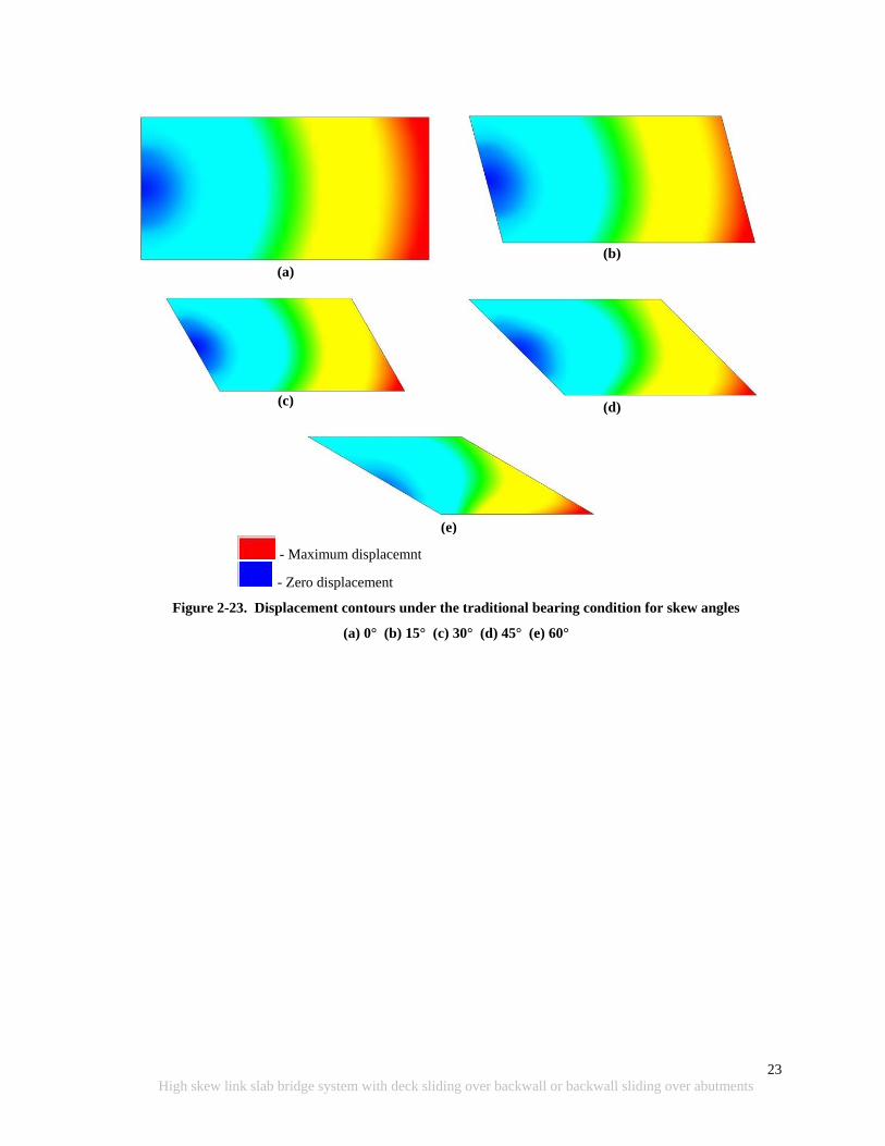
23
High skew link slab bridge system with deck sliding over backwall or backwall sliding over abutments
(a)
(b)
(c)
(d)
(e)
- Maximum displacemnt
- Zero displacement
Figure 2-23. Displacement contours under the traditional bearing condition for skew angles
(a) 0° (b) 15° (c) 30° (d) 45° (e) 60°
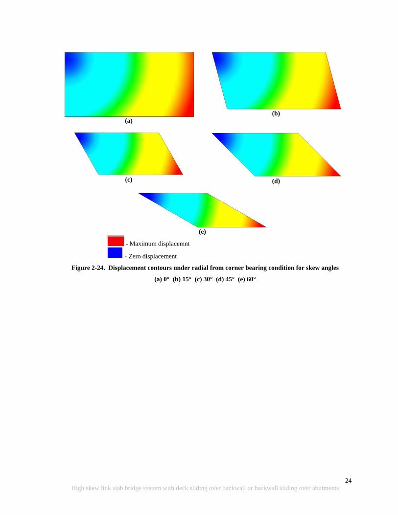
24
High skew link slab bridge system with deck sliding over backwall or backwall sliding over abutments
(a)
(b)
(c)
(d)
(e)
- Maximum displacemnt
- Zero displacement
Figure 2-24. Displacement contours under radial from corner bearing condition for skew angles
(a) 0° (b) 15° (c) 30° (d) 45° (e) 60°
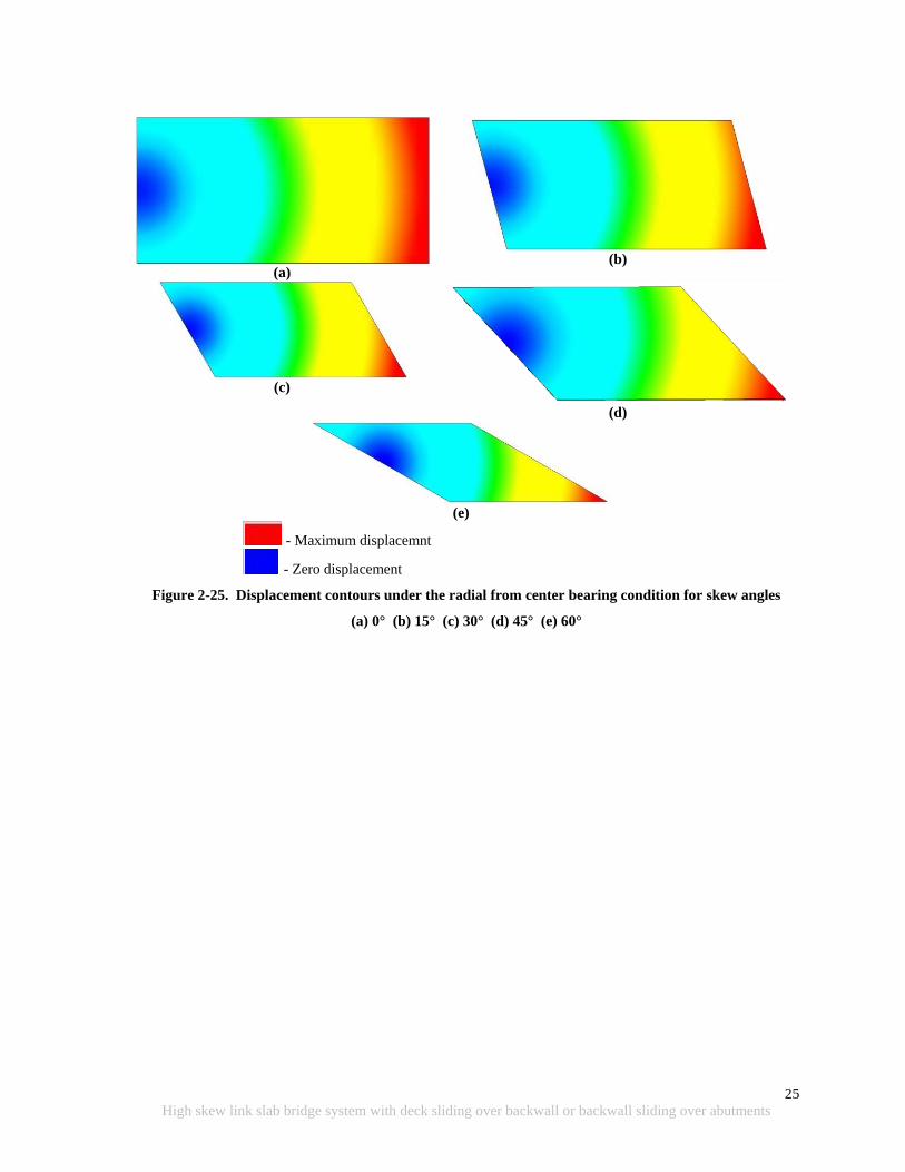
25
High skew link slab bridge system with deck sliding over backwall or backwall sliding over abutments
(a)
(b)
(c)
(d)
(e)
- Maximum displacemnt
- Zero displacement
Figure 2-25. Displacement contours under the radial from center bearing condition for skew angles
(a) 0° (b) 15° (c) 30° (d) 45° (e) 60°
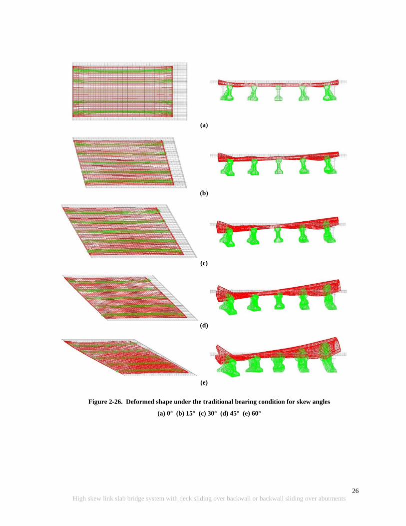
26
High skew link slab bridge system with deck sliding over backwall or backwall sliding over abutments
(a)
(b)
(c)
(d)
(e)
Figure 2-26. Deformed shape under the traditional bearing condition for skew angles
(a) 0° (b) 15° (c) 30° (d) 45° (e) 60°
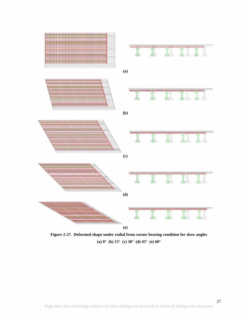
27
High skew link slab bridge system with deck sliding over backwall or backwall sliding over abutments
(a)
(b)
(c)
(d)
(e)
Figure 2-27. Deformed shape under radial from corner bearing condition for skew angles
(a) 0° (b) 15° (c) 30° (d) 45° (e) 60°

28
High skew link slab bridge system with deck sliding over backwall or backwall sliding over abutments
(a)
(b)
(c)
(d)
(e)
Figure 2-28. Deformed shape under radial from center bearing condition for skew angles
(a) 0° (b) 15° (c) 30° (d) 45° (e) 60°
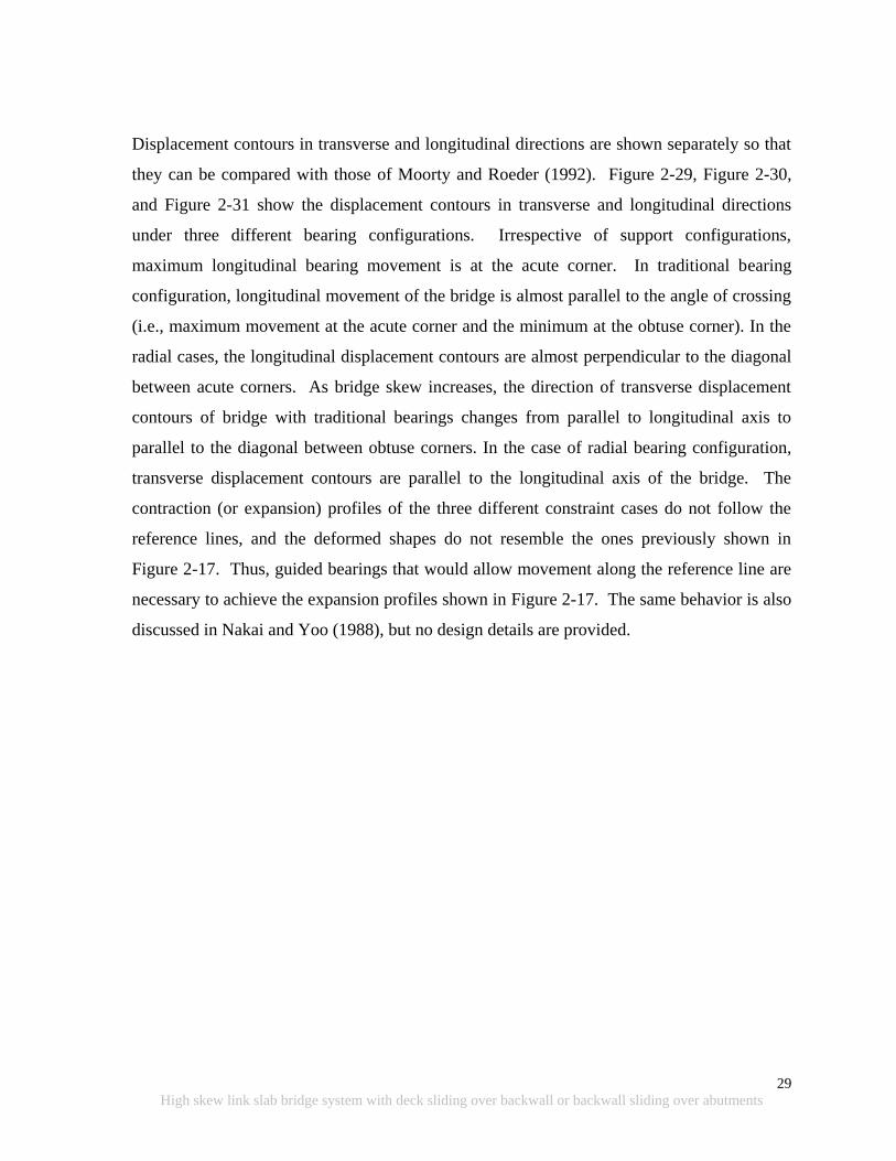
29
High skew link slab bridge system with deck sliding over backwall or backwall sliding over abutments
Displacement contours in transverse and longitudinal directions are shown separately so that
they can be compared with those of Moorty and Roeder (1992). Figure 2-29, Figure 2-30,
and Figure 2-31 show the displacement contours in transverse and longitudinal directions
under three different bearing configurations. Irrespective of support configurations,
maximum longitudinal bearing movement is at the acute corner. In traditional bearing
configuration, longitudinal movement of the bridge is almost parallel to the angle of crossing
(i.e., maximum movement at the acute corner and the minimum at the obtuse corner). In the
radial cases, the longitudinal displacement contours are almost perpendicular to the diagonal
between acute corners. As bridge skew increases, the direction of transverse displacement
contours of bridge with traditional bearings changes from parallel to longitudinal axis to
parallel to the diagonal between obtuse corners. In the case of radial bearing configuration,
transverse displacement contours are parallel to the longitudinal axis of the bridge. The
contraction (or expansion) profiles of the three different constraint cases do not follow the
reference lines, and the deformed shapes do not resemble the ones previously shown in
Figure 2-17. Thus, guided bearings that would allow movement along the reference line are
necessary to achieve the expansion profiles shown in Figure 2-17. The same behavior is also
discussed in Nakai and Yoo (1988), but no design details are provided.
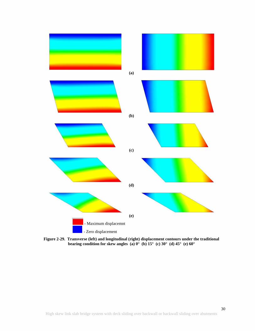
30
High skew link slab bridge system with deck sliding over backwall or backwall sliding over abutments
(a)
(b)
(c)
(d)
(e)
- Maximum displacemnt
- Zero displacement
Figure 2-29. Transverse (left) and longitudinal (right) displacement contours under the traditional
bearing condition for skew angles (a) 0° (b) 15° (c) 30° (d) 45° (e) 60°
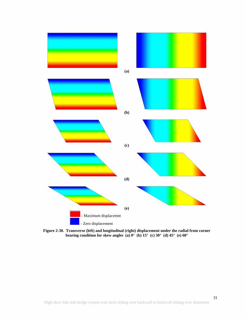
31
High skew link slab bridge system with deck sliding over backwall or backwall sliding over abutments
(a)
(b)
(c)
(d)
(e)
- Maximum displacemnt
- Zero displacement
Figure 2-30. Transverse (left) and longitudinal (right) displacement under the radial from corner
bearing condition for skew angles (a) 0° (b) 15° (c) 30° (d) 45° (e) 60°
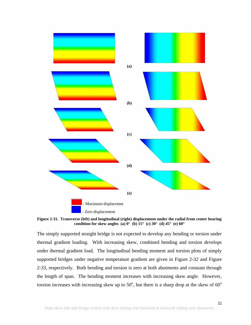
32
High skew link slab bridge system with deck sliding over backwall or backwall sliding over abutments
(a)
(b)
(c)
(d)
(e)
- Maximum displacemnt
- Zero displacement
Figure 2-31. Transverse (left) and longitudinal (right) displacement under the radial from center bearing
condition for skew angles (a) 0° (b) 15° (c) 30° (d) 45° (e) 60°
The simply supported straight bridge is not expected to develop any bending or torsion under
thermal gradient loading. With increasing skew, combined bending and torsion develops
under thermal gradient load. The longitudinal bending moment and torsion plots of simply
supported bridges under negative temperature gradient are given in Figure 2-32 and Figure
2-33, respectively. Both bending and torsion is zero at both abutments and constant through
the length of span. The bending moment increases with increasing skew angle. However,
torsion increases with increasing skew up to 50o, but there is a sharp drop at the skew of 60
o
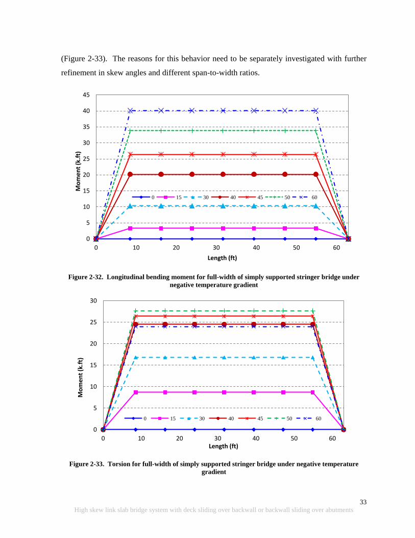
33
High skew link slab bridge system with deck sliding over backwall or backwall sliding over abutments
(Figure 2-33). The reasons for this behavior need to be separately investigated with further
refinement in skew angles and different span-to-width ratios.
Figure 2-32. Longitudinal bending moment for full-width of simply supported stringer bridge under
negative temperature gradient
Figure 2-33. Torsion for full-width of simply supported stringer bridge under negative temperature
gradient
0
5
10
15
20
25
30
35
40
45
0 10 20 30 40 50 60
Mo
me
nt
(k.f
t)
Length (ft)
0 15 30 40 45 50 60
0
5
10
15
20
25
30
0 10 20 30 40 50 60
Mo
me
nt
(k.f
t)
Length (ft)
0 15 30 40 45 50 60

34
High skew link slab bridge system with deck sliding over backwall or backwall sliding over abutments
2.4 DESIGN CHALLENGES OF SKEWED/JOINTLESS BRIDGES
2.4.1 Length, Skew and Curvature Limits
A typical maximum skew angle limit for jointless bridges specified by many states‟ highway
agencies (SHAs) is 30o (Oesterle et al. 1999). However, maximum limit angle varies from 0
o
to no limit (Chandra et al. 1995). A 2004 survey (Maruri and Petro 2005) revealed that a
majority of SHAs do not have restrictions on the maximum span length within the bridge, but
they do limit the total length and the skew angle.
Table 2-1 summarizes the span length, total bridge length, skew, and curvature limits for
prestressed concrete and steel girder bridges specified by the state highway agencies. The
table was developed from the responses of 39 SHAs. For the purposes of this survey, Maruri
and Petro (2005) specified bridge configurations as full integral abutment, semi-integral
abutment, deck extension, and integral pier configurations.
Table 2-1. Range of Design Criteria Used for Selection of Jointless Bridges
(Maruri and Petro 2005)
Girder Type PC Steel
Maximum Span (ft)
Full Integral 60-200 65-300
Semi-integral 90-200 65-200
Deck extensions 90-200 80-200
Integral piers 120-200 100-300
Maximum Total Bridge Length (ft)
Full Integral 150-1175 150-650
Semi-integral 90-3280 90-500
Deck extensions 200-750 200-450
Integral piers 300-400 150-1000
Maximum Skew (Degrees)
Full Integral 15-70 15-70
Semi-integral 20-45 30-40
Deck extensions 20-45 20-45
Integral piers 15-80 15-No Limit
Maximum Curvature (Degrees)
Full Integral 0-10 0-10
Semi-integral 0-10 0-10
Deck extensions 0-10 0-10
Integral piers 3-No Limit 0- No Limit

35
High skew link slab bridge system with deck sliding over backwall or backwall sliding over abutments
An additional point of reference outside the US is from the Ontario Ministry of
Transportation. They limit the overall length of semi-integral bridges to 492 ft (150m) based
on seasonal temperature variation considerations because of the capacity and efficiency of
movement systems (Husain and Bagnariol 1999).
2.4.2 Volume Change Loads and Behavior of Jointless Bridges
Maruri and Petro (2005) used the survey data to indentify the type of forces that states
account for in the design of integral abutments such as earth pressure, temperature, creep,
shrinkage, settlement, and additional forces due to skew or curvature (Figure 2-34).
Figure 2-34. Percent of states that account for different forces in the design of jointless bridges
(Maruri and Petro 2005).
Skew bridges respond to thermal loads with both longitudinal and transverse movements.
Transverse movement magnitude depends on bridge geometry, level of restraints at the piers
and abutments, skew or angle of crossing with respect to the abutments and/or piers, and
magnitude of the thermal loads (Oesterle et al. 1999). Forces developed at the abutments due
to thermal expansion are presented in Figure 2-35. According to Oesterle et al. (1999),
transverse forces developed in the system are high enough to cause abutment and wing-wall
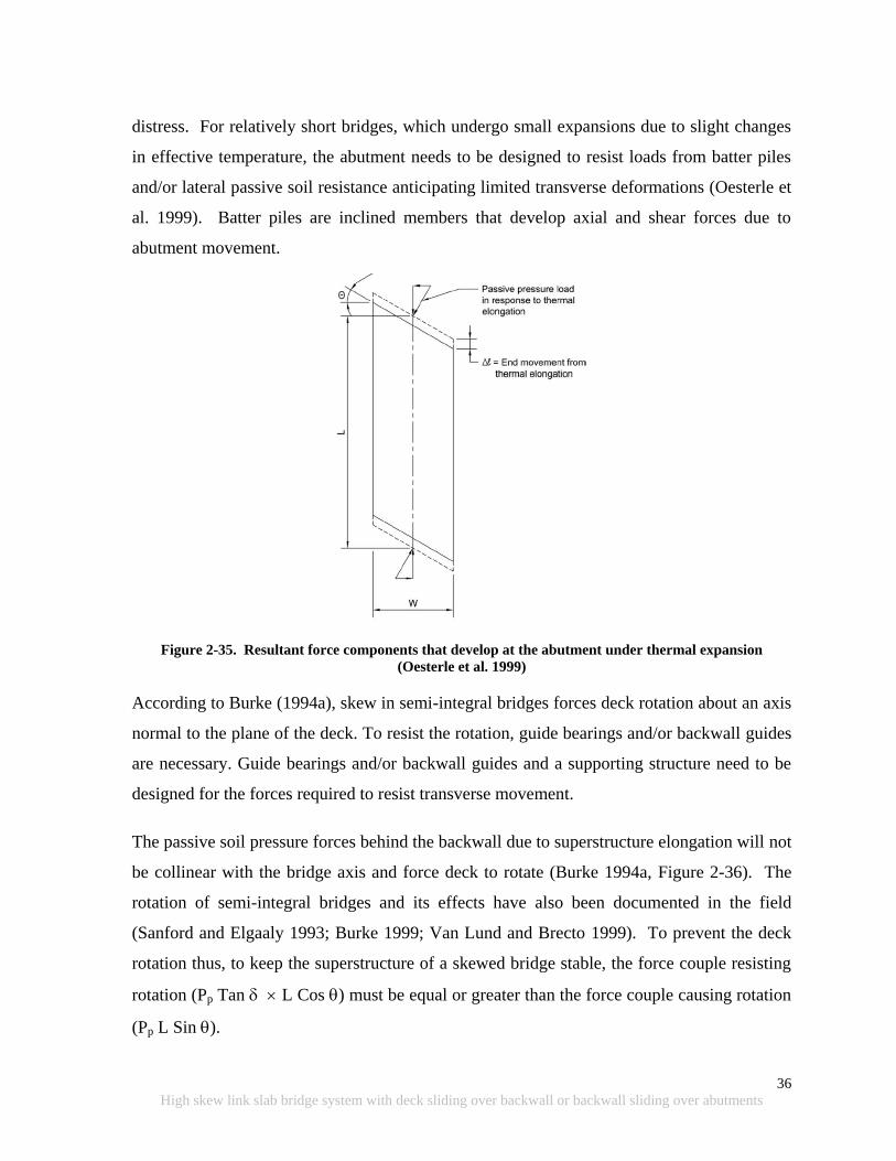
36
High skew link slab bridge system with deck sliding over backwall or backwall sliding over abutments
distress. For relatively short bridges, which undergo small expansions due to slight changes
in effective temperature, the abutment needs to be designed to resist loads from batter piles
and/or lateral passive soil resistance anticipating limited transverse deformations (Oesterle et
al. 1999). Batter piles are inclined members that develop axial and shear forces due to
abutment movement.
Figure 2-35. Resultant force components that develop at the abutment under thermal expansion
(Oesterle et al. 1999)
According to Burke (1994a), skew in semi-integral bridges forces deck rotation about an axis
normal to the plane of the deck. To resist the rotation, guide bearings and/or backwall guides
are necessary. Guide bearings and/or backwall guides and a supporting structure need to be
designed for the forces required to resist transverse movement.
The passive soil pressure forces behind the backwall due to superstructure elongation will not
be collinear with the bridge axis and force deck to rotate (Burke 1994a, Figure 2-36). The
rotation of semi-integral bridges and its effects have also been documented in the field
(Sanford and Elgaaly 1993; Burke 1999; Van Lund and Brecto 1999). To prevent the deck
rotation thus, to keep the superstructure of a skewed bridge stable, the force couple resisting
rotation (Pp Tan L Cos ) must be equal or greater than the force couple causing rotation
(Pp L Sin ).
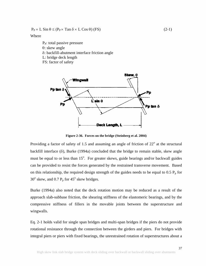
37
High skew link slab bridge system with deck sliding over backwall or backwall sliding over abutments
PP L Sin (PP Tan L Cos ) (FS) (2-1)
Where
PP: total passive pressure
: skew angle
: backfill-abutment interface friction angle
L: bridge deck length
FS: factor of safety
Figure 2-36. Forces on the bridge (Steinberg et al. 2004)
Providing a factor of safety of 1.5 and assuming an angle of friction of 22o at the structural
backfill interface (), Burke (1994a) concluded that the bridge to remain stable, skew angle
must be equal to or less than 15o. For greater skews, guide bearings and/or backwall guides
can be provided to resist the forces generated by the restrained transverse movement. Based
on this relationship, the required design strength of the guides needs to be equal to 0.5 Pp for
30o skew, and 0.7 Pp for 45
o skew bridges.
Burke (1994a) also noted that the deck rotation motion may be reduced as a result of the
approach slab-subbase friction, the shearing stiffness of the elastomeric bearings, and by the
compressive stiffness of fillers in the movable joints between the superstructure and
wingwalls.
Eq. 2-1 holds valid for single span bridges and multi-span bridges if the piers do not provide
rotational resistance through the connection between the girders and piers. For bridges with
integral piers or piers with fixed bearings, the unrestrained rotation of superstructures about a
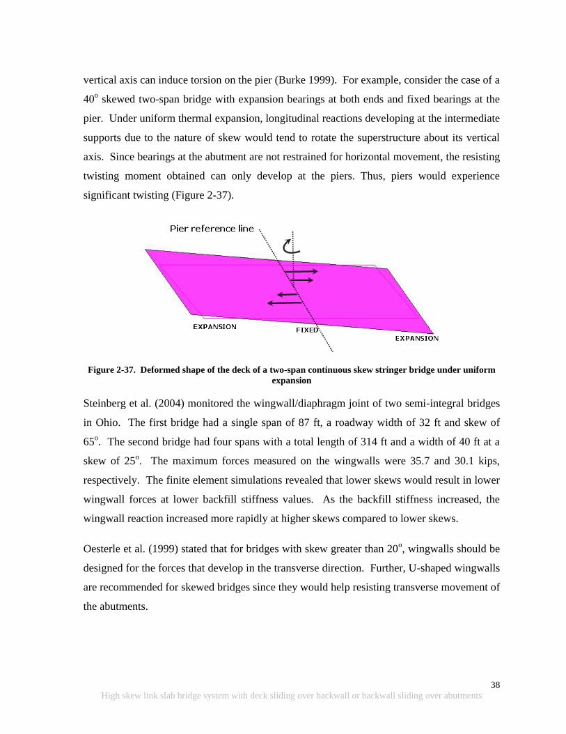
38
High skew link slab bridge system with deck sliding over backwall or backwall sliding over abutments
vertical axis can induce torsion on the pier (Burke 1999). For example, consider the case of a
40o skewed two-span bridge with expansion bearings at both ends and fixed bearings at the
pier. Under uniform thermal expansion, longitudinal reactions developing at the intermediate
supports due to the nature of skew would tend to rotate the superstructure about its vertical
axis. Since bearings at the abutment are not restrained for horizontal movement, the resisting
twisting moment obtained can only develop at the piers. Thus, piers would experience
significant twisting (Figure 2-37).
Figure 2-37. Deformed shape of the deck of a two-span continuous skew stringer bridge under uniform
expansion
Steinberg et al. (2004) monitored the wingwall/diaphragm joint of two semi-integral bridges
in Ohio. The first bridge had a single span of 87 ft, a roadway width of 32 ft and skew of
65o. The second bridge had four spans with a total length of 314 ft and a width of 40 ft at a
skew of 25o. The maximum forces measured on the wingwalls were 35.7 and 30.1 kips,
respectively. The finite element simulations revealed that lower skews would result in lower
wingwall forces at lower backfill stiffness values. As the backfill stiffness increased, the
wingwall reaction increased more rapidly at higher skews compared to lower skews.
Oesterle et al. (1999) stated that for bridges with skew greater than 20o, wingwalls should be
designed for the forces that develop in the transverse direction. Further, U-shaped wingwalls
are recommended for skewed bridges since they would help resisting transverse movement of
the abutments.
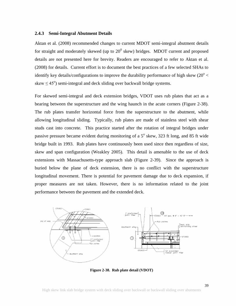
39
High skew link slab bridge system with deck sliding over backwall or backwall sliding over abutments
2.4.3 Semi-Integral Abutment Details
Aktan et al. (2008) recommended changes to current MDOT semi-integral abutment details
for straight and moderately skewed (up to 200 skew) bridges. MDOT current and proposed
details are not presented here for brevity. Readers are encouraged to refer to Aktan et al.
(2008) for details. Current effort is to document the best practices of a few selected SHAs to
identify key details/configurations to improve the durability performance of high skew (20o <
skew ≤ 45o) semi-integral and deck sliding over backwall bridge systems.
For skewed semi-integral and deck extension bridges, VDOT uses rub plates that act as a
bearing between the superstructure and the wing haunch in the acute corners (Figure 2-38).
The rub plates transfer horizontal force from the superstructure to the abutment, while
allowing longitudinal sliding. Typically, rub plates are made of stainless steel with shear
studs cast into concrete. This practice started after the rotation of integral bridges under
passive pressure became evident during monitoring of a 5o skew, 323 ft long, and 85 ft wide
bridge built in 1993. Rub plates have continuously been used since then regardless of size,
skew and span configuration (Weakley 2005). This detail is amenable to the use of deck
extensions with Massachusetts-type approach slab (Figure 2-39). Since the approach is
buried below the plane of deck extension, there is no conflict with the superstructure
longitudinal movement. There is potential for pavement damage due to deck expansion, if
proper measures are not taken. However, there is no information related to the joint
performance between the pavement and the extended deck.
Figure 2-38. Rub plate detail (VDOT)
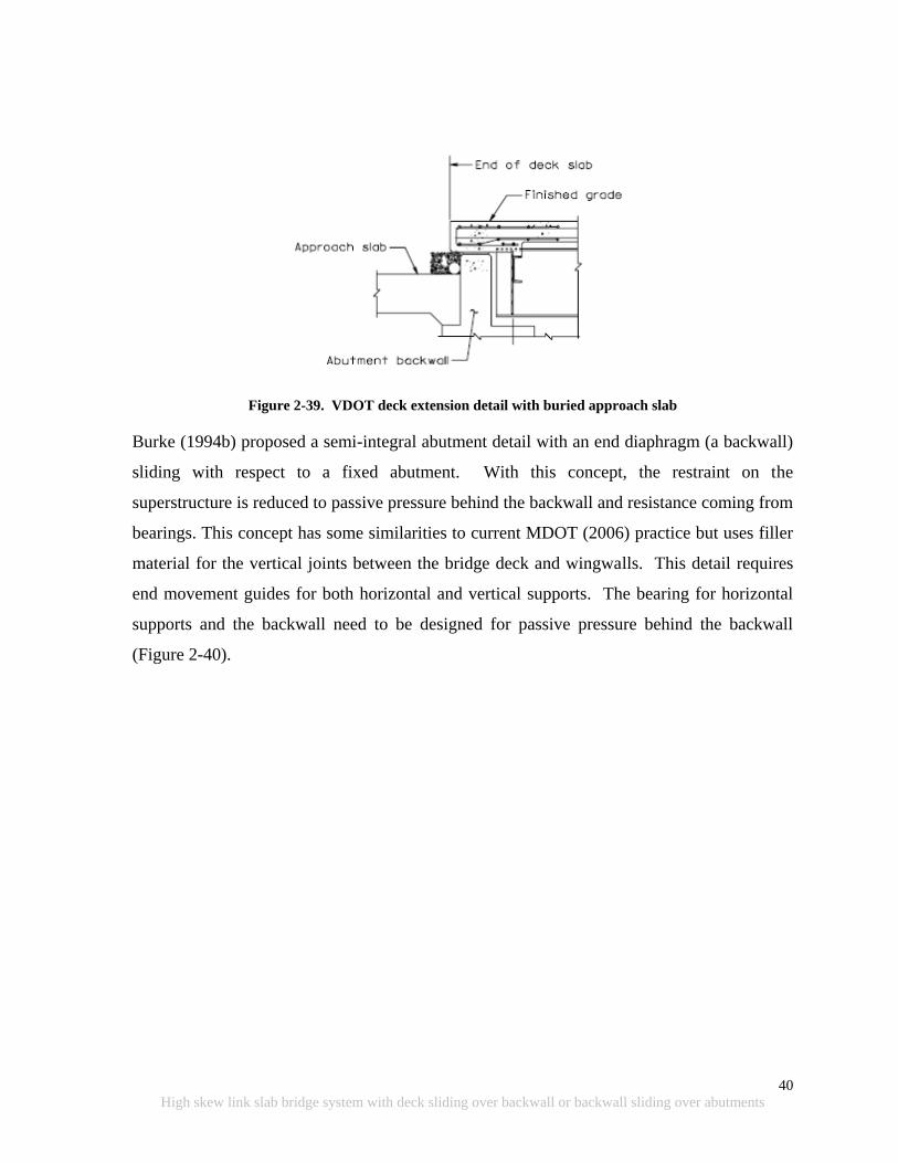
40
High skew link slab bridge system with deck sliding over backwall or backwall sliding over abutments
Figure 2-39. VDOT deck extension detail with buried approach slab
Burke (1994b) proposed a semi-integral abutment detail with an end diaphragm (a backwall)
sliding with respect to a fixed abutment. With this concept, the restraint on the
superstructure is reduced to passive pressure behind the backwall and resistance coming from
bearings. This concept has some similarities to current MDOT (2006) practice but uses filler
material for the vertical joints between the bridge deck and wingwalls. This detail requires
end movement guides for both horizontal and vertical supports. The bearing for horizontal
supports and the backwall need to be designed for passive pressure behind the backwall
(Figure 2-40).
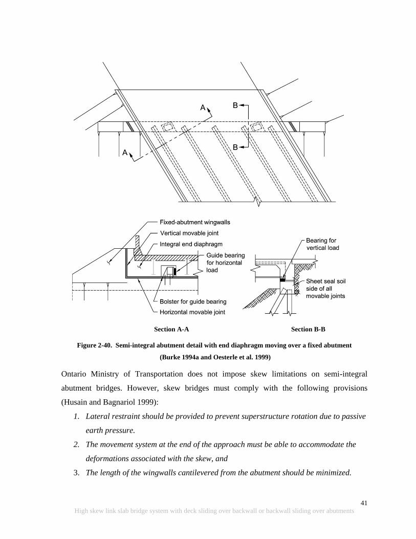
41
High skew link slab bridge system with deck sliding over backwall or backwall sliding over abutments
Section A-A Section B-B
Figure 2-40. Semi-integral abutment detail with end diaphragm moving over a fixed abutment
(Burke 1994a and Oesterle et al. 1999)
Ontario Ministry of Transportation does not impose skew limitations on semi-integral
abutment bridges. However, skew bridges must comply with the following provisions
(Husain and Bagnariol 1999):
1. Lateral restraint should be provided to prevent superstructure rotation due to passive
earth pressure.
2. The movement system at the end of the approach must be able to accommodate the
deformations associated with the skew, and
3. The length of the wingwalls cantilevered from the abutment should be minimized.
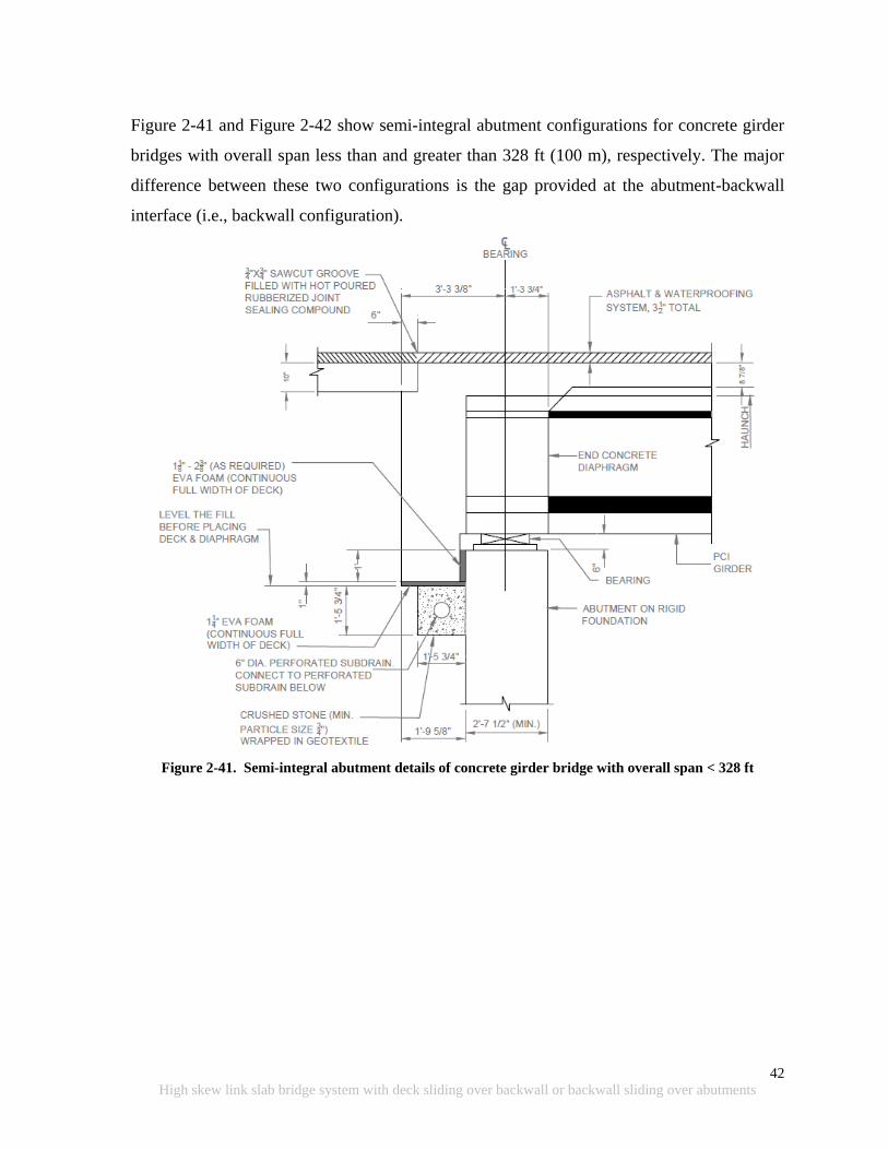
42
High skew link slab bridge system with deck sliding over backwall or backwall sliding over abutments
Figure 2-41 and Figure 2-42 show semi-integral abutment configurations for concrete girder
bridges with overall span less than and greater than 328 ft (100 m), respectively. The major
difference between these two configurations is the gap provided at the abutment-backwall
interface (i.e., backwall configuration).
Figure 2-41. Semi-integral abutment details of concrete girder bridge with overall span < 328 ft
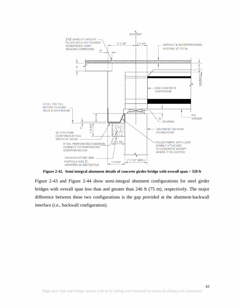
43
High skew link slab bridge system with deck sliding over backwall or backwall sliding over abutments
Figure 2-42. Semi-integral abutment details of concrete girder bridge with overall span > 328 ft
Figure 2-43 and Figure 2-44 show semi-integral abutment configurations for steel girder
bridges with overall span less than and greater than 246 ft (75 m), respectively. The major
difference between these two configurations is the gap provided at the abutment-backwall
interface (i.e., backwall configuration).
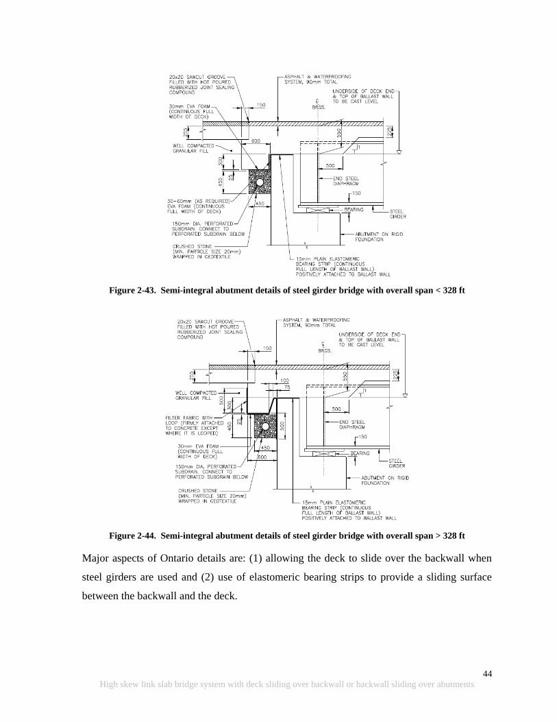
44
High skew link slab bridge system with deck sliding over backwall or backwall sliding over abutments
Figure 2-43. Semi-integral abutment details of steel girder bridge with overall span < 328 ft
Figure 2-44. Semi-integral abutment details of steel girder bridge with overall span > 328 ft
Major aspects of Ontario details are: (1) allowing the deck to slide over the backwall when
steel girders are used and (2) use of elastomeric bearing strips to provide a sliding surface
between the backwall and the deck.

45
High skew link slab bridge system with deck sliding over backwall or backwall sliding over abutments
2.4.4 EPS Backfill
As discussed in the previous section, passive pressure developed by backfill generates a
reactive force perpendicular to the backwall. In skew bridges, this force is not parallel to the
longitudinal axis and, in the absence of adequate restraints, the force rotates the
superstructure about an axis normal to the plane of the deck during bridge expansion.
Providing restrains to prevent the rotation can induce large forces at the abutments or
wingwalls. The high forces can cause cracking and other forms of distress if not properly
accounted for in the design. In order to minimize the reactive force development due to
backfill effects, expanded polystyrene (EPS) is being used by several states.
The Federal Highway Administration (FHWA) promotes the use of EPS geofoam as a
backfill material for accelerated bridge construction projects. Several advantages of using
EPS are rapid construction, reduced lateral load behind retaining structures, minimum
differential settlement, etc (FHWA 2011).
The advantage of using EPS behind the backwall of integral or semi-integral systems is the
attenuation of the effect of bridge movement on backfill during thermal expansion. Also, use
of EPS behind the backwall is an effective means of reducing properly compacted backfill
material settlement (Hoppe 2005). Figure 2-45 shows the abutment cross-section of
experimental implementation of EPS by Virginia DOT (VDOT) in a semi-integral bridge.

46
High skew link slab bridge system with deck sliding over backwall or backwall sliding over abutments
Figure 2-45. VDOT semi-integral system with EPS (Hoppe 2005)
The Structure and Bridge Manual of VDOT (2010) provides details on EPS implementation
shown in Figure 2-45. Eq. 2-2 is recommended by VDOT for calculating the EPS thickness.
EPS thickness (EPSt) = 10 [0.01 h + 0.67 ∆L] ≥ 10 in. (2-2)
where, h is the height of the backwall in inches and ∆L is the total bridge movement under
the full temperature range. VDOT (2010) recommends using the passive earth pressure
coefficient (Kp) of 4 when EPS is used behind the backwall and analysis of the backwall
considering a continuous beam supported by the girders. However, using field monitoring
data of a 450 skew integral abutment bridge, Hoppe and Bagnall (2008) demonstrated that the
Kp can be as low as 1.2 when the angle of backfill-abutment wall friction is 200 or 0.6 when
the angle of friction is zero. Field observations have shown that the skew bridge
superstructure rotation is as low as 50; hence, the interface angle of friction can be assumed
to be zero (Hoppe and Bagnall 2008).
EPS properties such as compressive stress, elastic limit strain, modulus, Poisson‟s ratio,
creep, durability, etc are discussed in the literature (Lutenegger and Ciufetti. 2009; Stark et
al. 2004). EPS material properties are controlled by its density. For EPS with 1.25 lb/ft3

47
High skew link slab bridge system with deck sliding over backwall or backwall sliding over abutments
density, the elastic property limit is at a compression strain of less than 1%. The special
provisions presented in Hoppe and Bagnall (2008) require providing EPS with linear-elastic
stress-strain behavior up to 10 percent strain. In addition to density, EPS compressive
strength is a nonlinear function of temperature. Strength remains constant for a temperature
less than 32 0F. When the temperature increases beyond 32
0F and up to 73
0F, strength
decreases at a rate of 7% per 18 0F. Conversely, temperate increase from 73
0F to 140
0F
increases EPS strength at a rate of 7% per 18 0F.
For calculating the Poisson‟s ratio () of EPS Lutenegger and Ciufetti (2009) proposed the
following equation:
= 0.091 + 0.0024 (2-3)
where is the density of EPS in lb/ft3.
According to Lutenegger and Ciufetti (2009), the coefficient of passive EPS pressure (Kp)
can be expressed in terms of Poisson‟s ratio as follows:
Kp = /(1 + ) (2-4)
For commonly available EPS, the passive earth pressure coefficient (Kp) ranges from 0.1 to
0.2, negligible for design. Lutenegger and Ciufetti (2009) state that the horizontal pressure,
when a uniformly distributed load is applied over EPS, is about 1/10th
of the vertical load.
This shows that the magnitude of overburden pressure should be considered in analysis rather
than using a constant value as recommended by VDOT. Creep of EPS is highly dependent on
temperature. For example, at 140 0F exposure compared to 73
0F, uniaxial strains increased
by 88% for 1.25 lb/ft3 density EPS under a sustained stress of 626 lb/ft
2 for approximately 3
months. However, when the sustained stress is increased to 835 lb/ft2, with all other
conditions remaining the same, creep strain increased to 195% (Lutenegger and Ciufetti
2009).
Norway has a long history of using EPS, and significant data has been collected on EPS
performance. According to Frydenlund and Aabøe (2001), EPS can be a very durable

48
High skew link slab bridge system with deck sliding over backwall or backwall sliding over abutments
material that can be used for a life cycle of 100 years provided that the buoyancy forces are
properly accounted, EPS is well protected from dissolving agents like gasoline, and the stress
level to which EPS is subjected is kept below 30-50% of its compressive strength.
Stark et al. (2004) illustrated some typical details of EPS abutment (Figure 2-46) where the
approach is directly supported by a sand subgrade placed over the EPS. This detail is not
preferable since the approach slab and the subgrade becomes a surcharge load over the EPS
fill, which will promote EPS creep. This surcharge load can be eliminated by including a
sleeper slab, to support the approach. From the design procedure presented by Stark et al.
(2004), only active soil pressure will be the load acting on the abutment when the approach
slab is supported by a sleeper slab. Passive earth pressure can be neglected as it can only
form under large deformation within the EPS. Considering all the benefits, EPS is a practical
solution to reduce the backfill effect on the backwall or abutment wall of skew bridges.
When the use of EPS is specified, a sleeper slab should be provided to support the approach
slab, buoyancy forces on the EPS should be accounted for in the design, and adequate
protection should be provided using geotextile and gasoline containment geomembranes.
Figure 2-46. Typical details of EPS abutment (Stark et al. 2004)
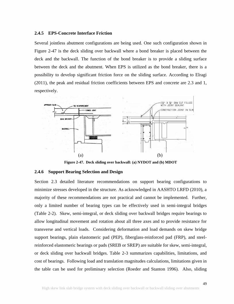
49
High skew link slab bridge system with deck sliding over backwall or backwall sliding over abutments
2.4.5 EPS-Concrete Interface Friction
Several jointless abutment configurations are being used. One such configuration shown in
Figure 2-47 is the deck sliding over backwall where a bond breaker is placed between the
deck and the backwall. The function of the bond breaker is to provide a sliding surface
between the deck and the abutment. When EPS is utilized as the bond breaker, there is a
possibility to develop significant friction force on the sliding surface. According to Elragi
(2011), the peak and residual friction coefficients between EPS and concrete are 2.3 and 1,
respectively.
(a)
(b)
Figure 2-47. Deck sliding over backwall: (a) NYDOT and (b) MDOT
2.4.6 Support Bearing Selection and Design
Section 2.3 detailed literature recommendations on support bearing configurations to
minimize stresses developed in the structure. As acknowledged in AASHTO LRFD (2010), a
majority of these recommendations are not practical and cannot be implemented. Further,
only a limited number of bearing types can be effectively used in semi-integral bridges
(Table 2-2). Skew, semi-integral, or deck sliding over backwall bridges require bearings to
allow longitudinal movement and rotation about all three axes and to provide resistance for
transverse and vertical loads. Considering deformation and load demands on skew bridge
support bearings, plain elastomeric pad (PEP), fiberglass-reinforced pad (FRP), and steel-
reinforced elastomeric bearings or pads (SREB or SREP) are suitable for skew, semi-integral,
or deck sliding over backwall bridges. Table 2-3 summarizes capabilities, limitations, and
cost of bearings. Following load and translation magnitudes calculations, limitations given in
the table can be used for preliminary selection (Roeder and Stanton 1996). Also, sliding

50
High skew link slab bridge system with deck sliding over backwall or backwall sliding over abutments
bearings can be combined with other types listed in Table 2-2 to accommodate large
movements (Roeder and Stanton 1996; Parke and Hewson 2008).
Table 2-2. Bearing Suitability (Source: AASHTO LRFD 2010)
Type of Bearing Movement
Rotation about Bridge
Axis Indicated Resistance to Loads
Long. Trans. Long. Trans. Vert. Long. Trans. Vert.
Plain Elastomeric Pad S S S S L L L L
Fiberglass-Reinforced Pad S S S S L L L L
Steel-Reinforced Pad S S S S L L L S
Plane Sliding Bearing S S U U S R R S
L: Suitable for limited applications; S: Suitable; R: May be suitable, but requires special
considerations or additional elements such as sliders or guideways; U: Unsuitable.
Table 2-3. Summary of Bearing Capabilities (Source: Roeder and Stanton 1996)
Type of Bearing Load (kip) Translation (in.)
Rotation
(Rad.) Cost
Min. Max. Min. Max. Limit Initial Maintenance
Plain Elastomeric Pads (PEP) 0 100 0 0.6 0.01 Low Low
Fiberglass-Reinforced Pad (FRP) 0 135 0 1 0.015 Low Low
Steel-Reinforced Elastomeric Bearing 50 785 0 4 0.04 Low Low
Flat PTFE (Polytetrafluorethylene)
Slider 0 > 2250 1 > 4 0 Low Moderate
Roeder and Stanton (1996) and Badie, et al. (2001) developed charts for use in preliminary
selection of bearings (Figure 2-48, Figure 2-49, Figure 2-50, and Figure 2-51). These charts
were developed for steel girder bridges. But, they are equally valid for PC girder bridges.
Other bearing types covered in the charts are pot bearing, cotton duck pads (CDP), and
random oriented fiber pads (ROFP).
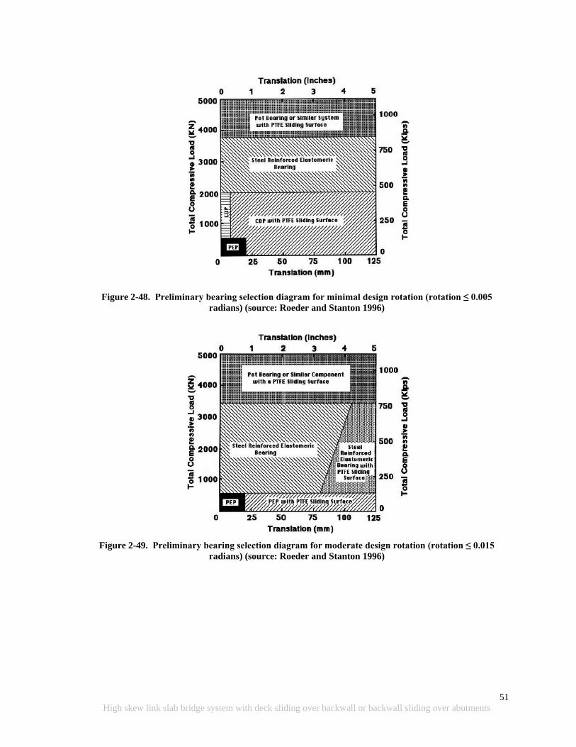
51
High skew link slab bridge system with deck sliding over backwall or backwall sliding over abutments
Figure 2-48. Preliminary bearing selection diagram for minimal design rotation (rotation ≤ 0.005
radians) (source: Roeder and Stanton 1996)
Figure 2-49. Preliminary bearing selection diagram for moderate design rotation (rotation ≤ 0.015
radians) (source: Roeder and Stanton 1996)
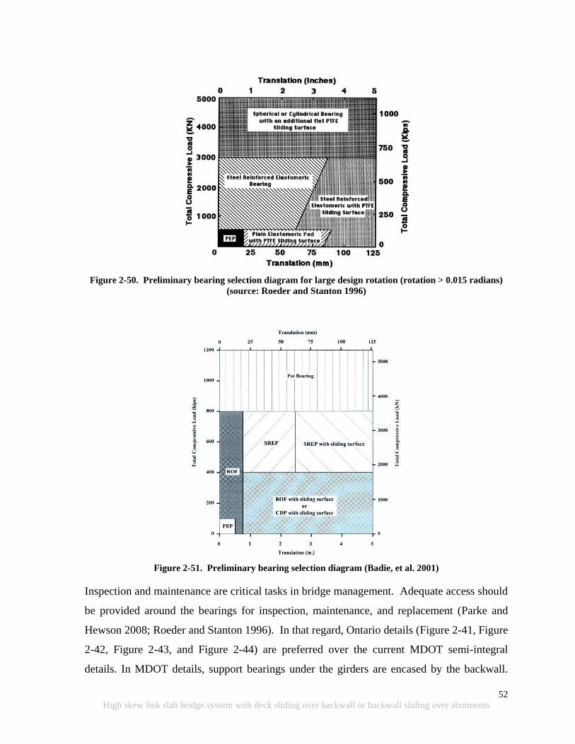
52
High skew link slab bridge system with deck sliding over backwall or backwall sliding over abutments
Figure 2-50. Preliminary bearing selection diagram for large design rotation (rotation > 0.015 radians)
(source: Roeder and Stanton 1996)
Figure 2-51. Preliminary bearing selection diagram (Badie, et al. 2001)
Inspection and maintenance are critical tasks in bridge management. Adequate access should
be provided around the bearings for inspection, maintenance, and replacement (Parke and
Hewson 2008; Roeder and Stanton 1996). In that regard, Ontario details (Figure 2-41, Figure
2-42, Figure 2-43, and Figure 2-44) are preferred over the current MDOT semi-integral
details. In MDOT details, support bearings under the girders are encased by the backwall.
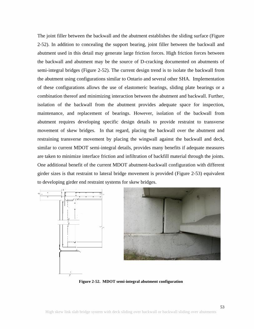
53
High skew link slab bridge system with deck sliding over backwall or backwall sliding over abutments
The joint filler between the backwall and the abutment establishes the sliding surface (Figure
2-52). In addition to concealing the support bearing, joint filler between the backwall and
abutment used in this detail may generate large friction forces. High friction forces between
the backwall and abutment may be the source of D-cracking documented on abutments of
semi-integral bridges (Figure 2-52). The current design trend is to isolate the backwall from
the abutment using configurations similar to Ontario and several other SHA. Implementation
of these configurations allows the use of elastomeric bearings, sliding plate bearings or a
combination thereof and minimizing interaction between the abutment and backwall. Further,
isolation of the backwall from the abutment provides adequate space for inspection,
maintenance, and replacement of bearings. However, isolation of the backwall from
abutment requires developing specific design details to provide restraint to transverse
movement of skew bridges. In that regard, placing the backwall over the abutment and
restraining transverse movement by placing the wingwall against the backwall and deck,
similar to current MDOT semi-integral details, provides many benefits if adequate measures
are taken to minimize interface friction and infiltration of backfill material through the joints.
One additional benefit of the current MDOT abutment-backwall configuration with different
girder sizes is that restraint to lateral bridge movement is provided (Figure 2-53) equivalent
to developing girder end restraint systems for skew bridges.
Figure 2-52. MDOT semi-integral abutment configuration
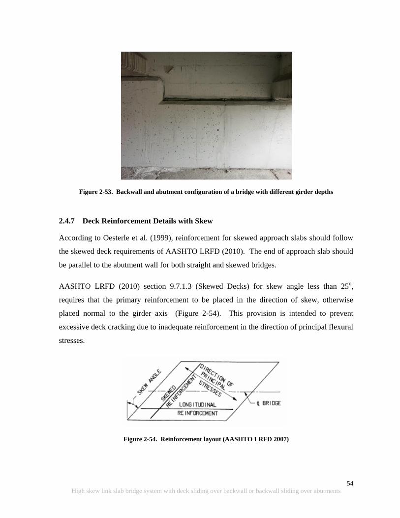
54
High skew link slab bridge system with deck sliding over backwall or backwall sliding over abutments
Figure 2-53. Backwall and abutment configuration of a bridge with different girder depths
2.4.7 Deck Reinforcement Details with Skew
According to Oesterle et al. (1999), reinforcement for skewed approach slabs should follow
the skewed deck requirements of AASHTO LRFD (2010). The end of approach slab should
be parallel to the abutment wall for both straight and skewed bridges.
AASHTO LRFD (2010) section 9.7.1.3 (Skewed Decks) for skew angle less than 25o,
requires that the primary reinforcement to be placed in the direction of skew, otherwise
placed normal to the girder axis (Figure 2-54). This provision is intended to prevent
excessive deck cracking due to inadequate reinforcement in the direction of principal flexural
stresses.
Figure 2-54. Reinforcement layout (AASHTO LRFD 2007)

55
High skew link slab bridge system with deck sliding over backwall or backwall sliding over abutments
According to section 9.7.2.5 (Reinforcement Requirements - Empirical Design) of AASHTO
LRFD (2010), for a skew angle over 25°, the specified reinforcement in both directions shall
be doubled in the end zones of the deck. Each end zone is the longitudinal distance equal to
the effective length of the slab. This provision is also intended for crack control. It was
documented that bridge decks with a skew greater than 25° have shown torsional cracks due
to differential deflections in the end zone (OHBDC 1991). The extent of documented
cracking was usually limited to a width equal to the effective length.
The MDOT Bridge Design Guide section 6.41.01 specifies bridge deck reinforcement layout
when the deck is designed based on load factor method. “S along the skew” should be used to
determine the slab reinforcement where S is the beam spacing minus the top flange width for
slab on prestressed concrete I beams and beam spacing minus half flange width for slab on
steel beams. If the angle of crossing is 70o or greater (i.e., skew is equal or less than 30
o),
transverse bars are placed parallel to the reference lines if “S along the skew” falls in the
same beam spacing range as “S normal to the beams” or the next larger range.
According to the MDOT Bridge Design Guide section 6.41.02 (Standard Bridge Slabs –
Empirical Design), transverse bars may be placed parallel to the reference lines if the angle
of crossing is 65o or greater (i.e., skew is equal or less than 35
o); they should otherwise be
placed perpendicular to the bridge centerline. End zone reinforcement is required for both
simply supported and continuous spans as shown in Figure 2-55.

56
High skew link slab bridge system with deck sliding over backwall or backwall sliding over abutments
Figure 2-55. End zone reinforcement details (MDOT Bridge Design Guide 6.41.02)
2.5 FIELD PERFORMANCE OF SKEWED/JOINTLESS BRIDGES
The MDOT Structural Research Unit conducted field inspection of eight MDOT bridges that
have link slab detail and were constructed between 2001 and 2003 (Gilani and Jansson
2004). Two of the bridges had moderate and high skew angles.
S08-63101 is a 26o skewed four-span steel bridge with a link slab over the center pier that
was constructed in 2001 as part of a deck replacement project. Review of construction
documents revealed that the longitudinal reinforcement was under-designed for HS-25 live
loading. Inspection documented hairline cracks on the link slab within 1-2 feet of the saw
cut region (Figure 2-56). Crack widths ranged between 0.002 and 0.004 inches. The rest of
the link slab area was crack free.
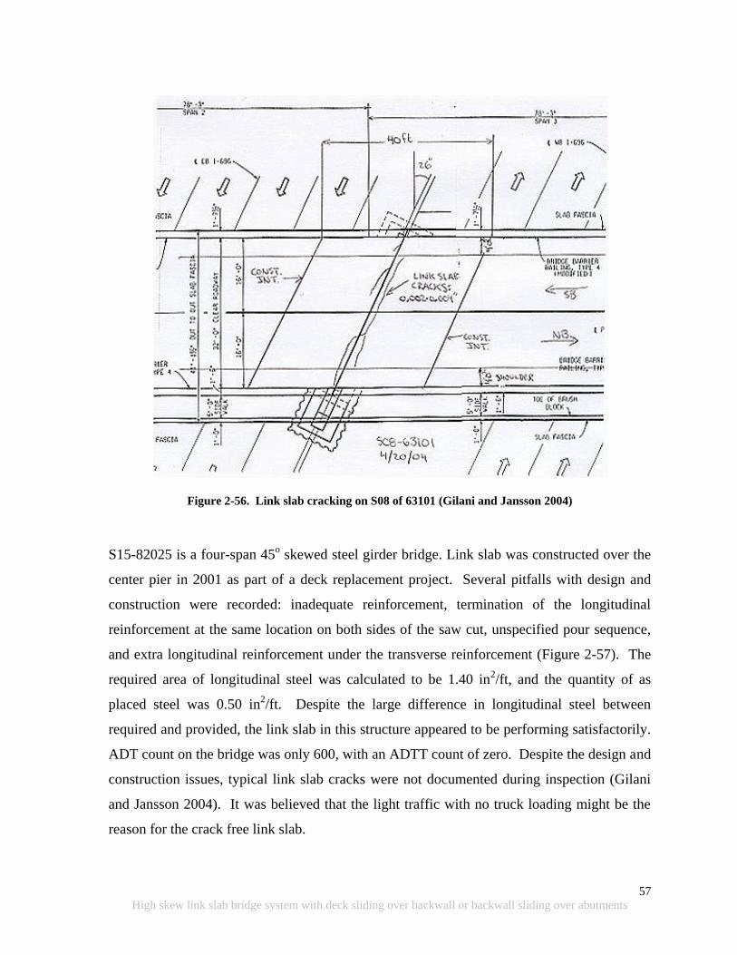
57
High skew link slab bridge system with deck sliding over backwall or backwall sliding over abutments
Figure 2-56. Link slab cracking on S08 of 63101 (Gilani and Jansson 2004)
S15-82025 is a four-span 45o skewed steel girder bridge. Link slab was constructed over the
center pier in 2001 as part of a deck replacement project. Several pitfalls with design and
construction were recorded: inadequate reinforcement, termination of the longitudinal
reinforcement at the same location on both sides of the saw cut, unspecified pour sequence,
and extra longitudinal reinforcement under the transverse reinforcement (Figure 2-57). The
required area of longitudinal steel was calculated to be 1.40 in2/ft, and the quantity of as
placed steel was 0.50 in2/ft. Despite the large difference in longitudinal steel between
required and provided, the link slab in this structure appeared to be performing satisfactorily.
ADT count on the bridge was only 600, with an ADTT count of zero. Despite the design and
construction issues, typical link slab cracks were not documented during inspection (Gilani
and Jansson 2004). It was believed that the light traffic with no truck loading might be the
reason for the crack free link slab.
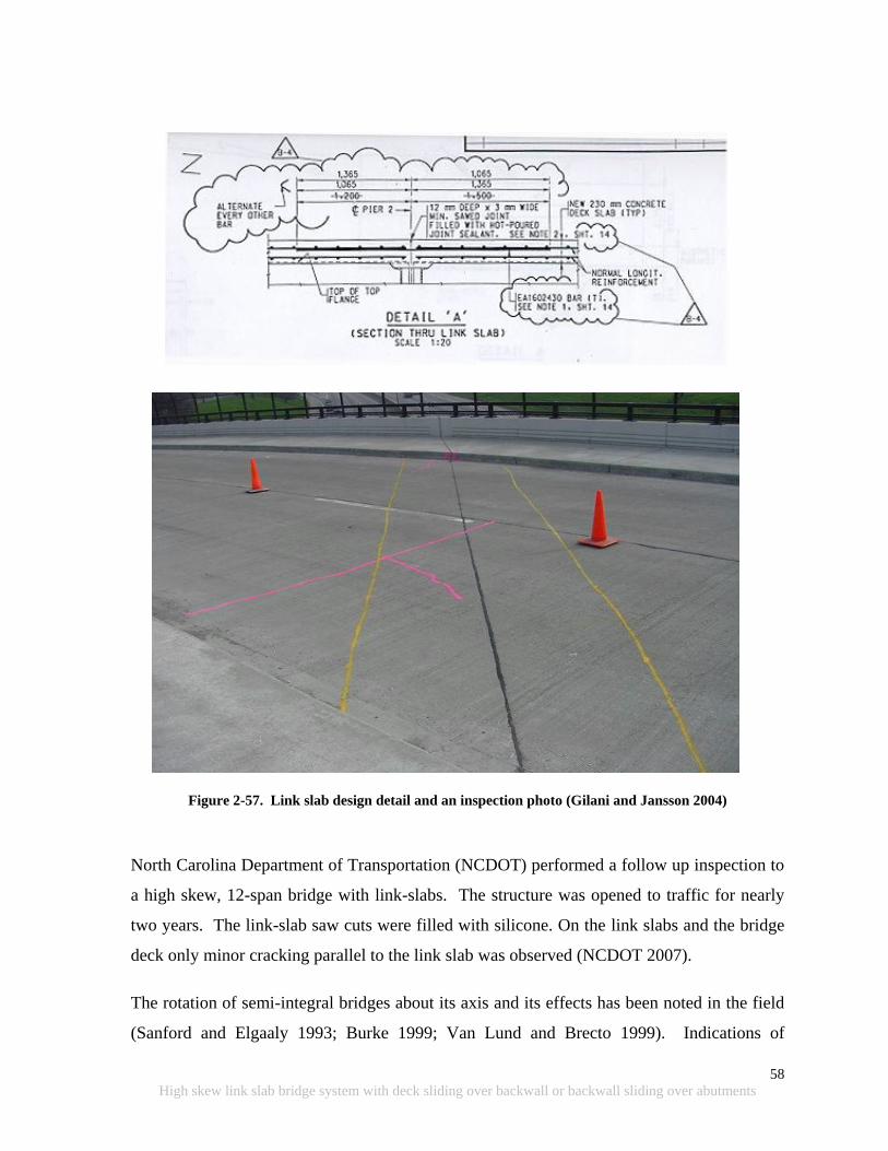
58
High skew link slab bridge system with deck sliding over backwall or backwall sliding over abutments
Figure 2-57. Link slab design detail and an inspection photo (Gilani and Jansson 2004)
North Carolina Department of Transportation (NCDOT) performed a follow up inspection to
a high skew, 12-span bridge with link-slabs. The structure was opened to traffic for nearly
two years. The link-slab saw cuts were filled with silicone. On the link slabs and the bridge
deck only minor cracking parallel to the link slab was observed (NCDOT 2007).
The rotation of semi-integral bridges about its axis and its effects has been noted in the field
(Sanford and Elgaaly 1993; Burke 1999; Van Lund and Brecto 1999). Indications of

59
High skew link slab bridge system with deck sliding over backwall or backwall sliding over abutments
significant transverse movement of abutments in bridges with high skews and/or horizontal
curves were observed. Transverse movement of integral abutments should be accounted for
in the design details for barrier walls, drainage structures, and the ends of the approach slabs
(Tabatabai et al. 2005).
Figure 2-58 shows the abutment wall cracks near an acute corner of a two-span 45o skew
bridge that sits on semi-integral abutments. The bridge was constructed in 1969 with an
overall length of 292 ft and a width of 38 ft. The end-diaphragm moves with the
superstructure that slides longitudinally, and it is guided transversely by relatively stiff
abutments. Cracks in the abutment wall near the acute corner were perhaps caused by
transverse forces (Nicholson et al. 1997 and Oesterle et al. 1999).
Figure 2-58. Abutment wall cracking near an acute corner of the superstructure
(Nicholson et al. 1997 and Oesterle et al. 1999)
The Ontario Ministry of Transportation (OMOT) utilized various semi-integral abutment
configurations since late 1960s. The most recent configuration, superseded by the details
shown in Figure 2-41 to Figure 2-44, is shown in Figure 2-59. Use of this configuration was
discontinued because the neoprene or rubber bearing pads placed in between the backwall
and abutment wall did not prevent ingress of backfill material (Husain and Bagnariol 1999).
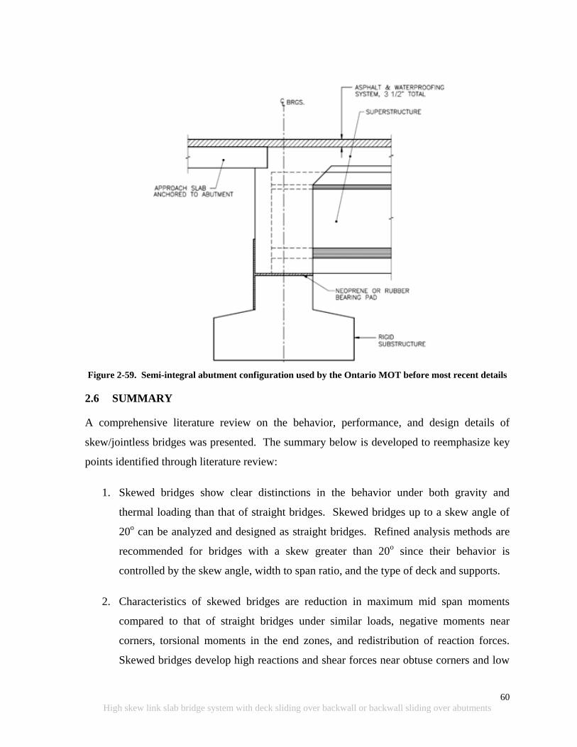
60
High skew link slab bridge system with deck sliding over backwall or backwall sliding over abutments
Figure 2-59. Semi-integral abutment configuration used by the Ontario MOT before most recent details
2.6 SUMMARY
A comprehensive literature review on the behavior, performance, and design details of
skew/jointless bridges was presented. The summary below is developed to reemphasize key
points identified through literature review:
1. Skewed bridges show clear distinctions in the behavior under both gravity and
thermal loading than that of straight bridges. Skewed bridges up to a skew angle of
20o can be analyzed and designed as straight bridges. Refined analysis methods are
recommended for bridges with a skew greater than 20o since their behavior is
controlled by the skew angle, width to span ratio, and the type of deck and supports.
2. Characteristics of skewed bridges are reduction in maximum mid span moments
compared to that of straight bridges under similar loads, negative moments near
corners, torsional moments in the end zones, and redistribution of reaction forces.
Skewed bridges develop high reactions and shear forces near obtuse corners and low
61
High skew link slab bridge system with deck sliding over backwall or backwall sliding over abutments
reactions, and possibly uplift at acute corners. In general, negative moments are
developed closed to obtuse corners; negative moments are a possibility at acute
corners if uplift is prevented (Hambly 1991).
3. Skewed bridges with semi-integral abutments would tend to rotate about an axis
normal to their horizontal plane. The rotation is due to the passive pressure
developed behind the backwall under thermal expansion. Deck extensions also have
a tendency to develop in-plane rotations but not as critical as semi-integral systems.
In both deck extension and semi-integral systems, the rotation may be affected by the
approach slab-subbase friction, the shearing resistance of the elastomers in the
bearings, and by the compressive resistance of fillers used in the movable joints
between the superstructure and wingwalls.
4. The current MDOT deck sliding over backwall system uses EPS in between deck and
backwall to introduce the sliding surface. The EPS elastic strain limit is very small
and can deform beyond the elastic limit under deck self-weight and live loads.
Further, peak and residual friction coefficients between EPS and concrete are 2.3 and
1.0, respectively. Because of these reasons, neoprene pads over the backwall may be
used. In addition, a polyethylene sheet used under the approach should be extended
to the backwall face on the span side to minimize friction at the interface.
5. The current semi-integral configuration used by Ontario and several State Highway
Agencies has the advantages of allowing the backwall to move independently from
the abutment, providing access space for bearing inspection, maintenance, and
replacement; and preventing backfill infiltration through the backwall.
6. Isolation of the backwall from the abutment requires developing specific design
details to constrain transverse movement of skew bridges. In that regard, placing the
backwall over the abutment and restraining transverse movement by placing the
wingwall against the backwall and deck, similar to current MDOT semi-integral
details, provides many benefits if adequate measures are taken to minimize interface
friction and infiltration of backfill material through the joints. Use of EPS from

62
High skew link slab bridge system with deck sliding over backwall or backwall sliding over abutments
behind the backwall helps reduce passive earth pressure and prevents infiltration of
backfill material.
7. One additional benefit of the current MDOT abutment-backwall configuration with
different girder sizes is that restraint to lateral bridge movement is provided
equivalent to developing girder end restraint systems for skew bridges. Adequate
measures should be taken to minimize interface friction and infiltration of backfill
material through the joints.
8. Ontario uses EVA (Ethylene vinyl acetate, commonly known as expanded rubber or
foam rubber) between the vertical faces of the backwall and abutment wall in order to
allow the backwall to move independently from the abutment. EVA has a wider
elastic range than EPS. On the other hand, the durability performance of EVA has not
been documented.
9. In order to allow the translation and rotation of skew bridges and provide sufficient
load capacity, plain elastomeric pad (PEP), fiberglass-reinforced pad (FRP), and
steel-reinforced elastomeric bearings or pads (SREB or SREP) are suitable for
support bearings for semi-integral and deck sliding over backwall bridges. Also,
PTFE sliding bearings can be combined with the support bearing types stated above
to accommodate large superstructure movements. PTFE sliding bearings can be
specified for most of the short and medium span bridges when girder end rotations are
not critical.
10. Rub plates, girder stops, or any other mechanism that is designed to resist large forces
is needed to control lateral movement of skew bridges.
11. With increasing backfill stiffness, forces at wingwalls of high skew bridges increase
dramatically. EPS can be specified as a suitable backfill material for semi-integral
bridges to reduce passive pressure. However, the approach slab should not be
directly supported on EPS because of potential creep. EPS should also be protected
using geotextiles and gasoline containment geomembranes.

63
High skew link slab bridge system with deck sliding over backwall or backwall sliding over abutments
3 MODELING AND FIELD TESTING OF A HIGH SKEW BRIDGE
3.1 OBJECTIVE AND APPROACH
The objective of this chapter is to document high skew bridge load response to truck and
thermal loads. Reactions and deformations of the bridge are also obtained by finite element
(FE) analysis and compared with the measured deflections and translations. Field
measurements were made using a non-contact Laser Tracker. This chapter details the bridge
configuration, instrumentation and measurement process, and FE bridge model development
and analysis. The chapter also includes measurements and comparisons to the FE analysis
results.
3.2 BRIDGE DESCRIPTION
The bridge (S12 of 03035) is located in Allegan, Michigan, and carries I-196 over Ottogan
Street (one mile east of Holland city limits (Figure 3-1 and Figure 3-2)). The 120 ft long, 44
ft wide, single span simply supported bridge has a 420 skew and carries two lanes of traffic
(Figure 3-3). The bridge superstructure consists of seven steel built-up I-girders with cast-in-
place concrete deck. The elevation and cross-section of the bridge is shown in Figure 3-4.
The girders are connected transversely via “intermediate diaphragms” within the span and
“end diaphragms” at both ends of the bridge. The diaphragm labels, locations, and cross-
sections are shown in Figure 3-5 and Figure 3-6. The girders back into concrete backwalls at
both ends as shown in Figure 3-7. The bridge is supported on the north abutment by a fixed
bearing and on the south abutment by an expansion bearing (Figure 3-9), respectively. The
expansion bearings are orientated along the bridge axis.
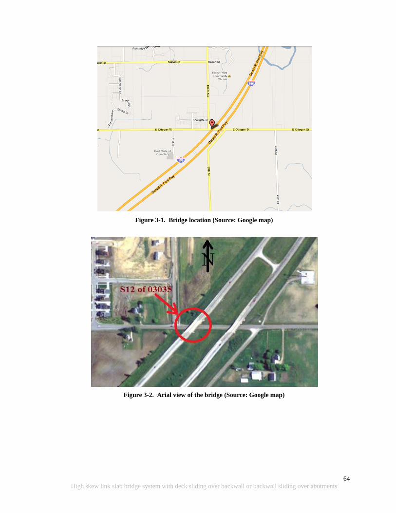
64
High skew link slab bridge system with deck sliding over backwall or backwall sliding over abutments
Figure 3-1. Bridge location (Source: Google map)
Figure 3-2. Arial view of the bridge (Source: Google map)
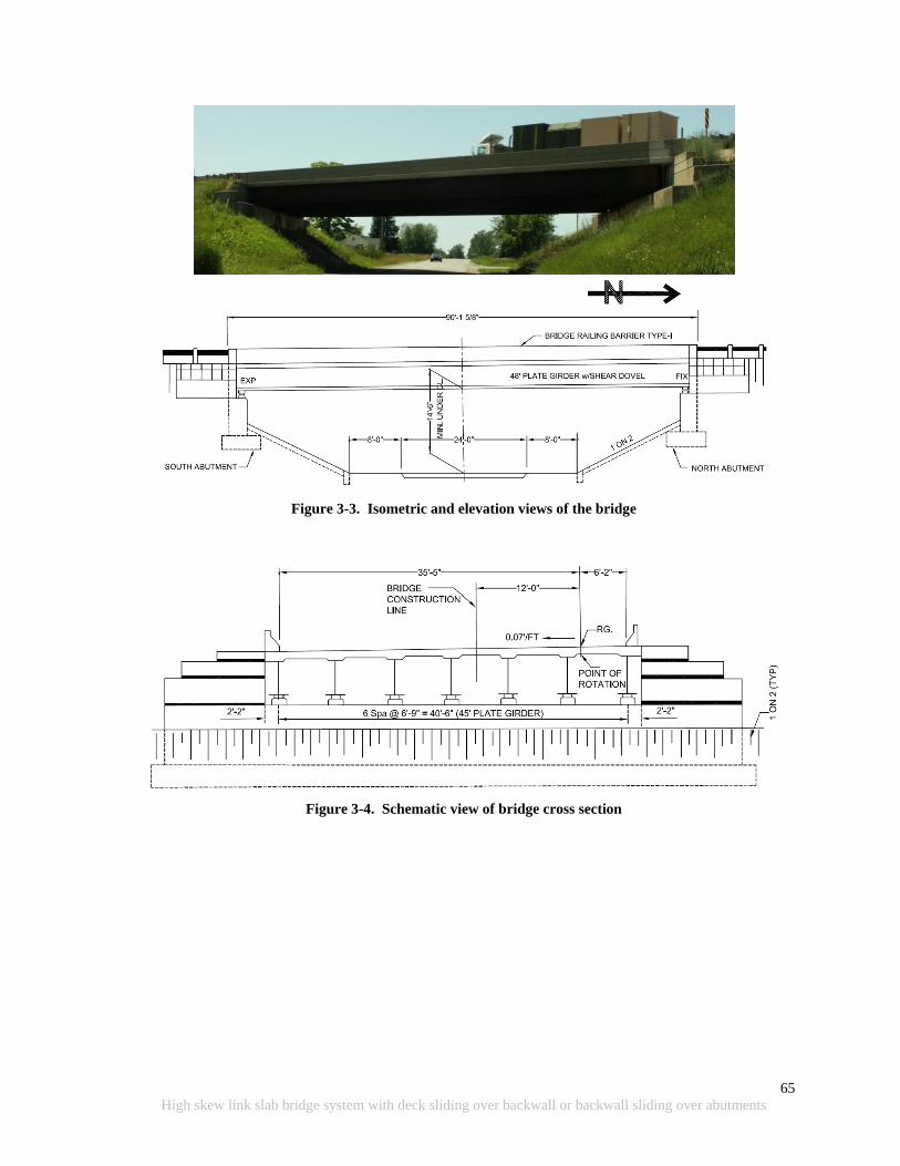
65
High skew link slab bridge system with deck sliding over backwall or backwall sliding over abutments
Figure 3-3. Isometric and elevation views of the bridge
Figure 3-4. Schematic view of bridge cross section
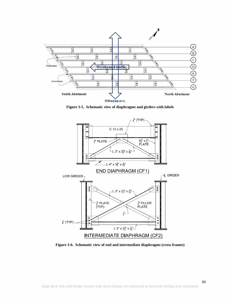
66
High skew link slab bridge system with deck sliding over backwall or backwall sliding over abutments
Figure 3-5. Schematic view of diaphragms and girders with labels
Figure 3-6. Schematic view of end and intermediate diaphragms (cross frames)
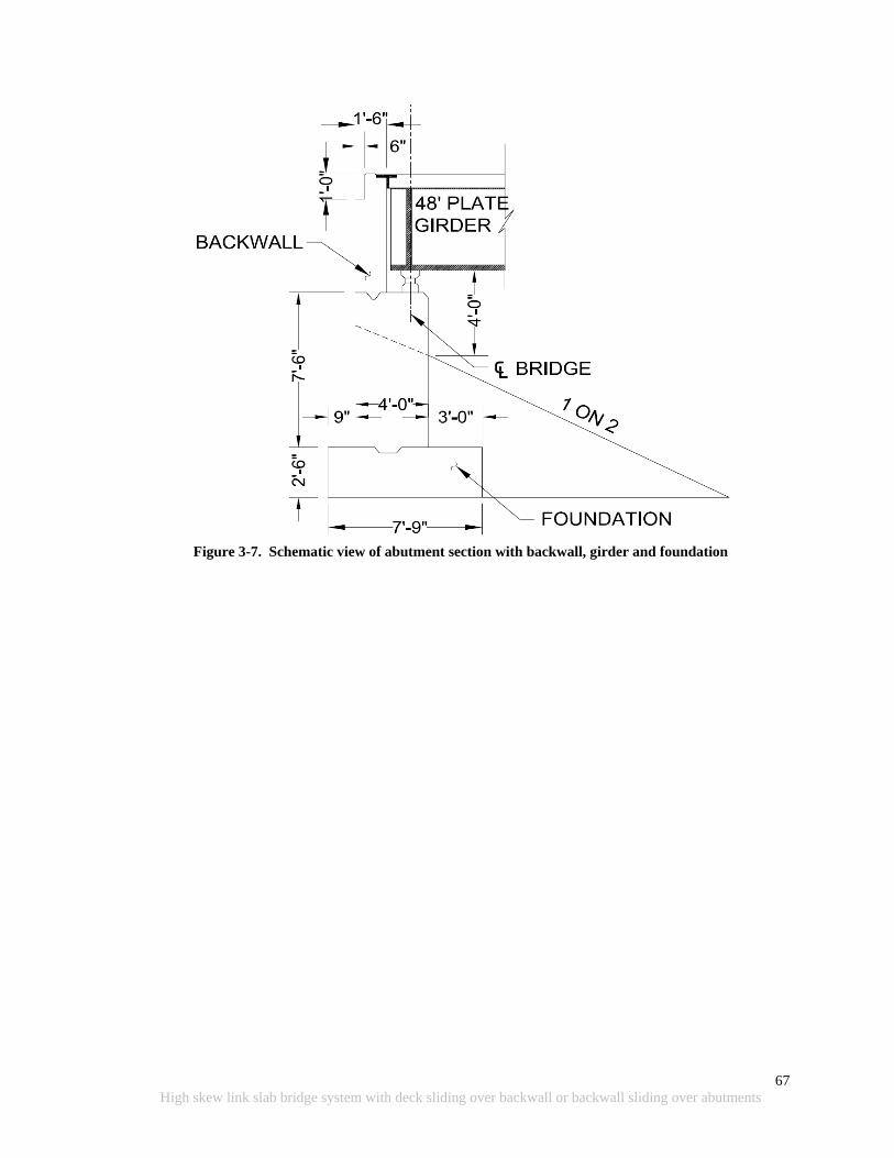
67
High skew link slab bridge system with deck sliding over backwall or backwall sliding over abutments
Figure 3-7. Schematic view of abutment section with backwall, girder and foundation
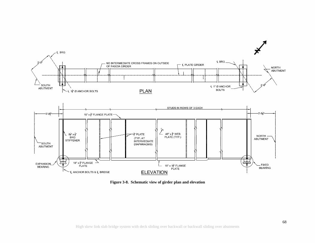
68
High skew link slab bridge system with deck sliding over backwall or backwall sliding over abutments
Figure 3-8. Schematic view of girder plan and elevation
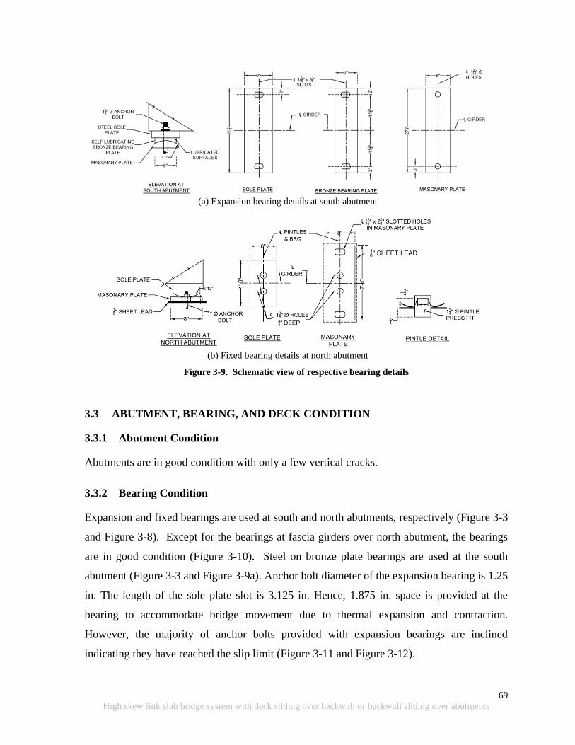
69
High skew link slab bridge system with deck sliding over backwall or backwall sliding over abutments
(a) Expansion bearing details at south abutment
(b) Fixed bearing details at north abutment
Figure 3-9. Schematic view of respective bearing details
3.3 ABUTMENT, BEARING, AND DECK CONDITION
3.3.1 Abutment Condition
Abutments are in good condition with only a few vertical cracks.
3.3.2 Bearing Condition
Expansion and fixed bearings are used at south and north abutments, respectively (Figure 3-3
and Figure 3-8). Except for the bearings at fascia girders over north abutment, the bearings
are in good condition (Figure 3-10). Steel on bronze plate bearings are used at the south
abutment (Figure 3-3 and Figure 3-9a). Anchor bolt diameter of the expansion bearing is 1.25
in. The length of the sole plate slot is 3.125 in. Hence, 1.875 in. space is provided at the
bearing to accommodate bridge movement due to thermal expansion and contraction.
However, the majority of anchor bolts provided with expansion bearings are inclined
indicating they have reached the slip limit (Figure 3-11 and Figure 3-12).
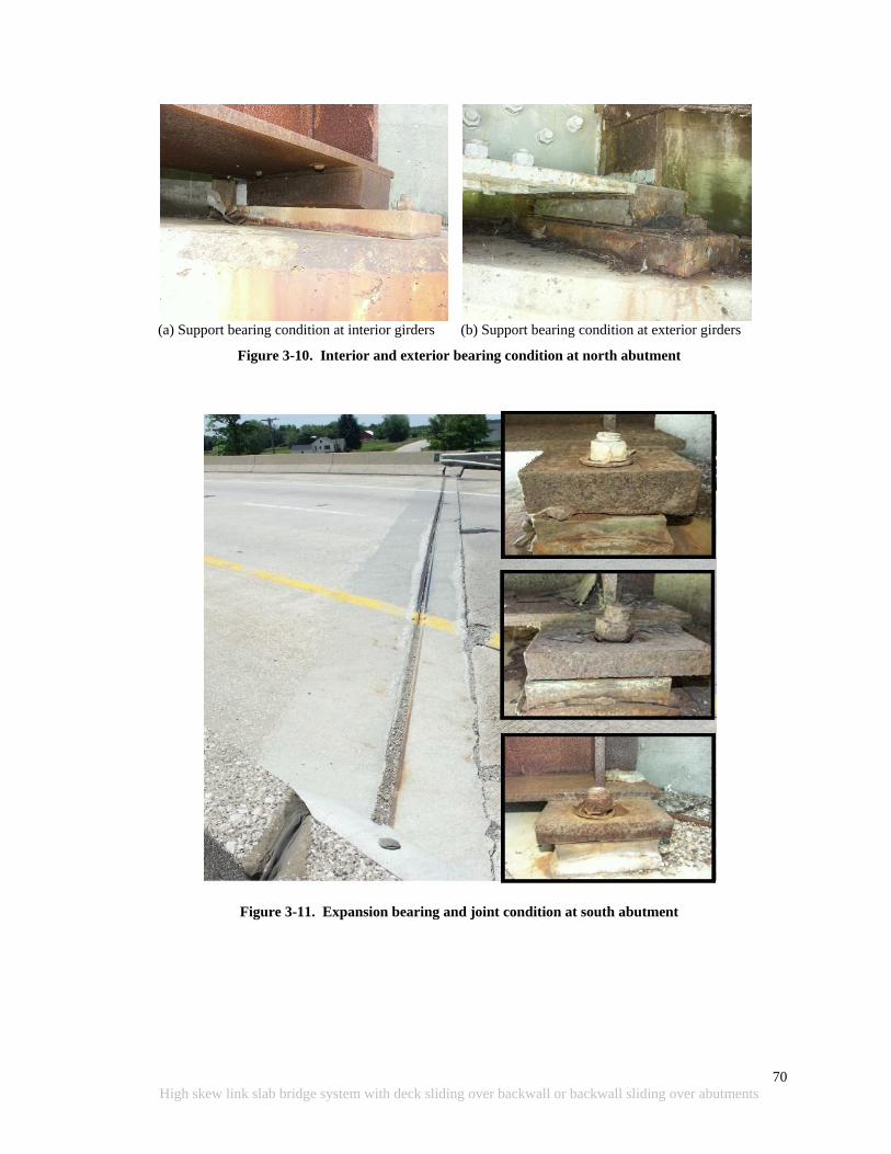
70
High skew link slab bridge system with deck sliding over backwall or backwall sliding over abutments
(a) Support bearing condition at interior girders (b) Support bearing condition at exterior girders
Figure 3-10. Interior and exterior bearing condition at north abutment
Figure 3-11. Expansion bearing and joint condition at south abutment
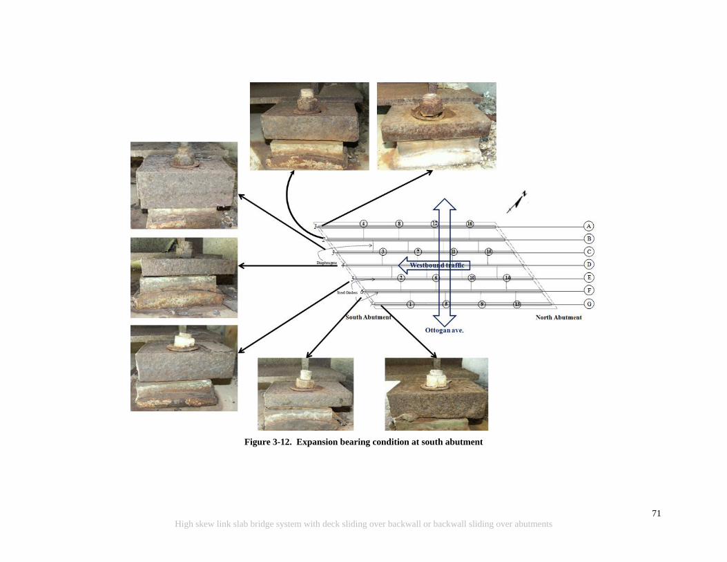
71
High skew link slab bridge system with deck sliding over backwall or backwall sliding over abutments
Figure 3-12. Expansion bearing condition at south abutment
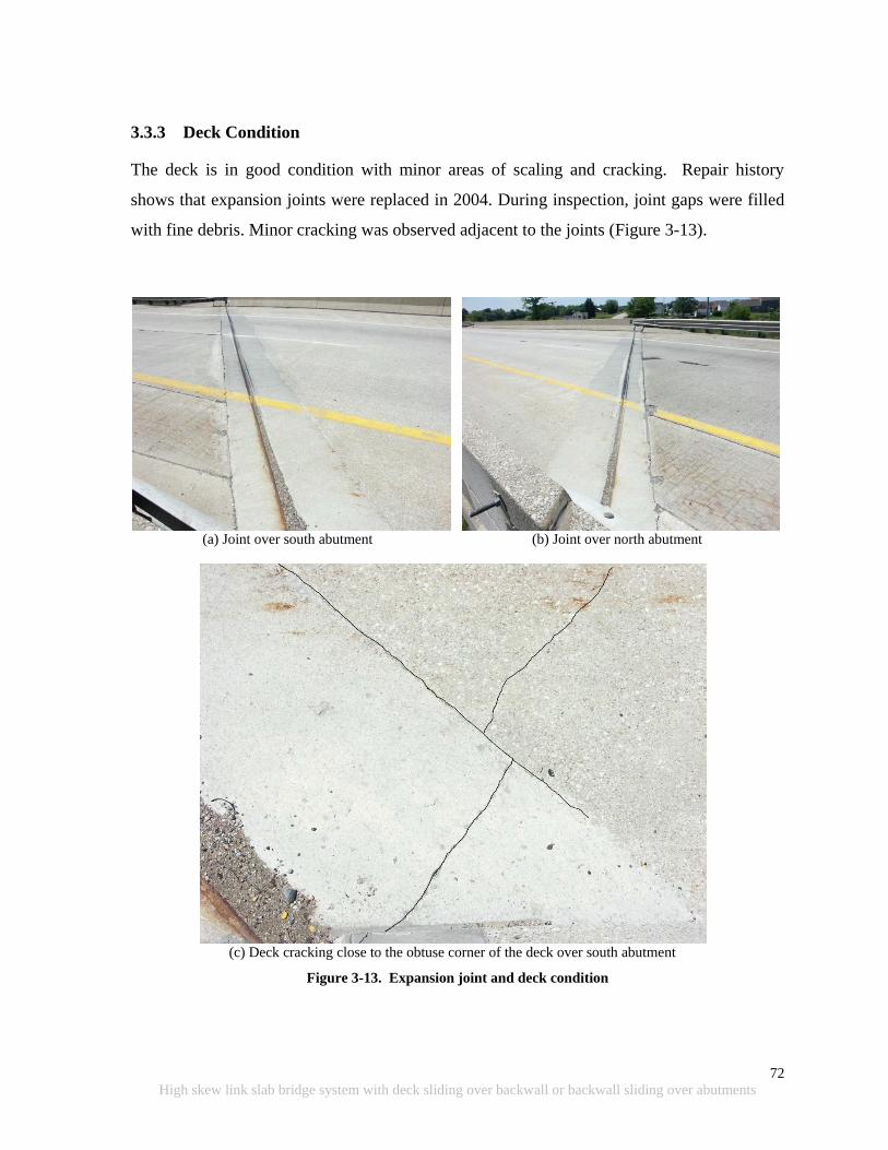
72
High skew link slab bridge system with deck sliding over backwall or backwall sliding over abutments
3.3.3 Deck Condition
The deck is in good condition with minor areas of scaling and cracking. Repair history
shows that expansion joints were replaced in 2004. During inspection, joint gaps were filled
with fine debris. Minor cracking was observed adjacent to the joints (Figure 3-13).
(a) Joint over south abutment (b) Joint over north abutment
(c) Deck cracking close to the obtuse corner of the deck over south abutment
Figure 3-13. Expansion joint and deck condition
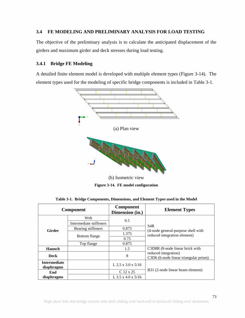
73
High skew link slab bridge system with deck sliding over backwall or backwall sliding over abutments
3.4 FE MODELING AND PRELIMINARY ANALYSIS FOR LOAD TESTING
The objective of the preliminary analysis is to calculate the anticipated displacement of the
girders and maximum girder and deck stresses during load testing.
3.4.1 Bridge FE Modeling
A detailed finite element model is developed with multiple element types (Figure 3-14). The
element types used for the modeling of specific bridge components is included in Table 3-1.
(a) Plan view
(b) Isometric view
Figure 3-14. FE model configuration
Table 3-1. Bridge Components, Dimensions, and Element Types used in the Model
Component Component
Dimension (in.) Element Types
Girder
Web 0.5
S4R
(4-node general-purpose shell with
reduced integration element)
Intermediate stiffeners
Bearing stiffeners 0.875
Bottom flange 1.375
0.75
Top flange 0.875
Haunch 1.5 C3D8R (8-node linear brick with
reduced integration)
C3D6 (6-node linear triangular prism) Deck 8
Intermediate
diaphragms L 2.5 x 3.0 x 5/16
B31 (2-node linear beam element) End
diaphragms
C 12 x 25
L 3.5 x 4.0 x 5/16

74
High skew link slab bridge system with deck sliding over backwall or backwall sliding over abutments
3.4.2 Truck Placement and Loading Configurations
The bridge is to be loaded using two trucks (Truck 04-1666 and Truck 04-1568 with axle
dimensions and wheel loads shown in Figure 3-15) in four configurations as depicted in
Figure 3-16 and Figure 3-17.
(a) Truck configuration
(b) Wheel loads (GVW: Gross Vehicle Weight)
Figure 3-15. Truck configuration and wheel loads
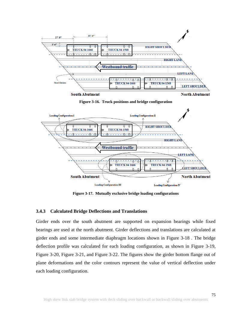
75
High skew link slab bridge system with deck sliding over backwall or backwall sliding over abutments
Figure 3-16. Truck positions and bridge configuration
Figure 3-17. Mutually exclusive bridge loading configurations
3.4.3 Calculated Bridge Deflections and Translations
Girder ends over the south abutment are supported on expansion bearings while fixed
bearings are used at the north abutment. Girder deflections and translations are calculated at
girder ends and some intermediate diaphragm locations shown in Figure 3-18 . The bridge
deflection profile was calculated for each loading configuration, as shown in Figure 3-19,
Figure 3-20, Figure 3-21, and Figure 3-22. The figures show the girder bottom flange out of
plane deformations and the color contours represent the value of vertical deflection under
each loading configuration.
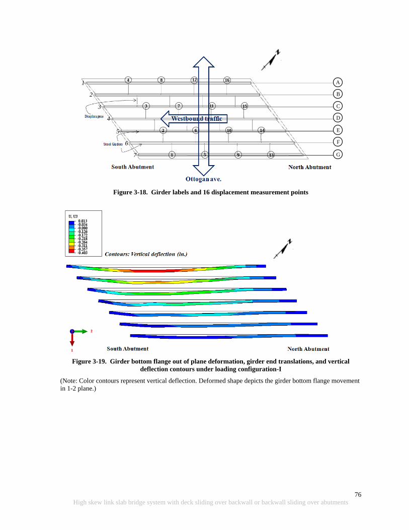
76
High skew link slab bridge system with deck sliding over backwall or backwall sliding over abutments
Figure 3-18. Girder labels and 16 displacement measurement points
Figure 3-19. Girder bottom flange out of plane deformation, girder end translations, and vertical
deflection contours under loading configuration-I
(Note: Color contours represent vertical deflection. Deformed shape depicts the girder bottom flange movement
in 1-2 plane.)
A
B
C
D
E
F
G1
4
2
3
8
6
7
5 9
10
11
12 16
15
14
13
1
2
3
4
5
6
7
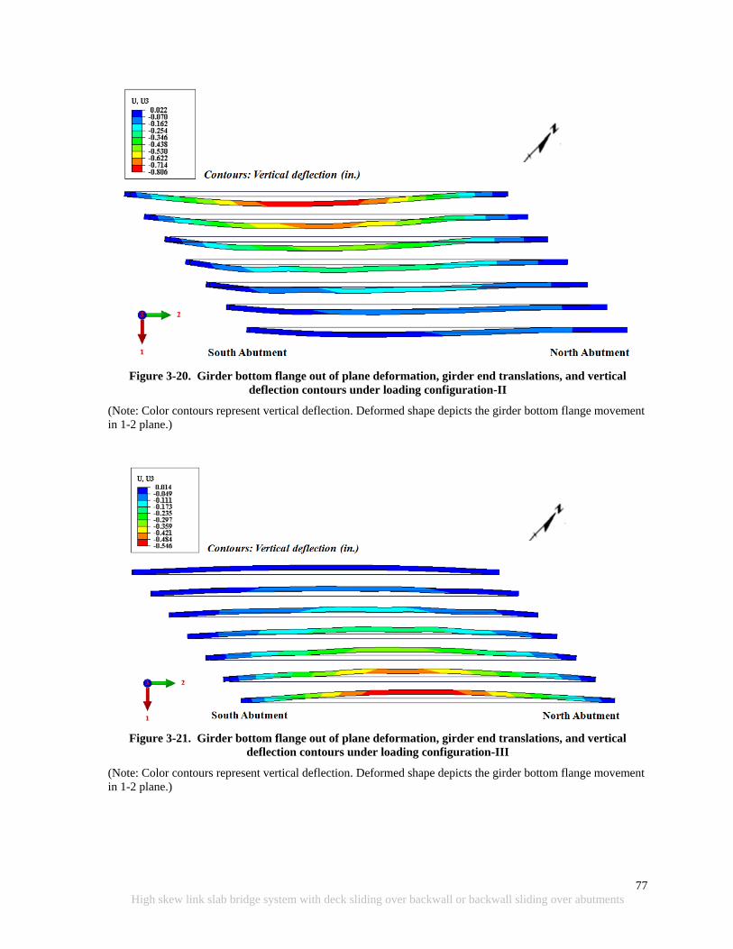
77
High skew link slab bridge system with deck sliding over backwall or backwall sliding over abutments
Figure 3-20. Girder bottom flange out of plane deformation, girder end translations, and vertical
deflection contours under loading configuration-II
(Note: Color contours represent vertical deflection. Deformed shape depicts the girder bottom flange movement
in 1-2 plane.)
Figure 3-21. Girder bottom flange out of plane deformation, girder end translations, and vertical
deflection contours under loading configuration-III
(Note: Color contours represent vertical deflection. Deformed shape depicts the girder bottom flange movement
in 1-2 plane.)
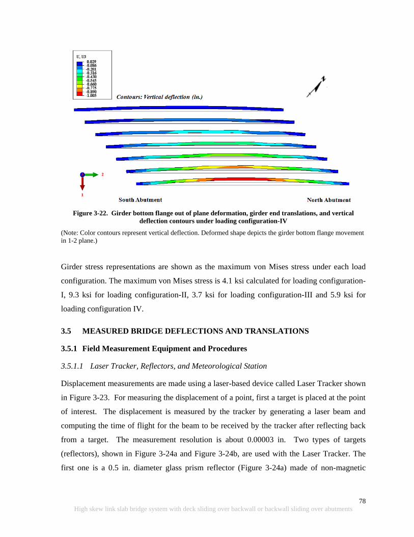
78
High skew link slab bridge system with deck sliding over backwall or backwall sliding over abutments
Figure 3-22. Girder bottom flange out of plane deformation, girder end translations, and vertical
deflection contours under loading configuration-IV
(Note: Color contours represent vertical deflection. Deformed shape depicts the girder bottom flange movement
in 1-2 plane.)
Girder stress representations are shown as the maximum von Mises stress under each load
configuration. The maximum von Mises stress is 4.1 ksi calculated for loading configuration-
I, 9.3 ksi for loading configuration-II, 3.7 ksi for loading configuration-III and 5.9 ksi for
loading configuration IV.
3.5 MEASURED BRIDGE DEFLECTIONS AND TRANSLATIONS
3.5.1 Field Measurement Equipment and Procedures
3.5.1.1 Laser Tracker, Reflectors, and Meteorological Station
Displacement measurements are made using a laser-based device called Laser Tracker shown
in Figure 3-23. For measuring the displacement of a point, first a target is placed at the point
of interest. The displacement is measured by the tracker by generating a laser beam and
computing the time of flight for the beam to be received by the tracker after reflecting back
from a target. The measurement resolution is about 0.00003 in. Two types of targets
(reflectors), shown in Figure 3-24a and Figure 3-24b, are used with the Laser Tracker. The
first one is a 0.5 in. diameter glass prism reflector (Figure 3-24a) made of non-magnetic
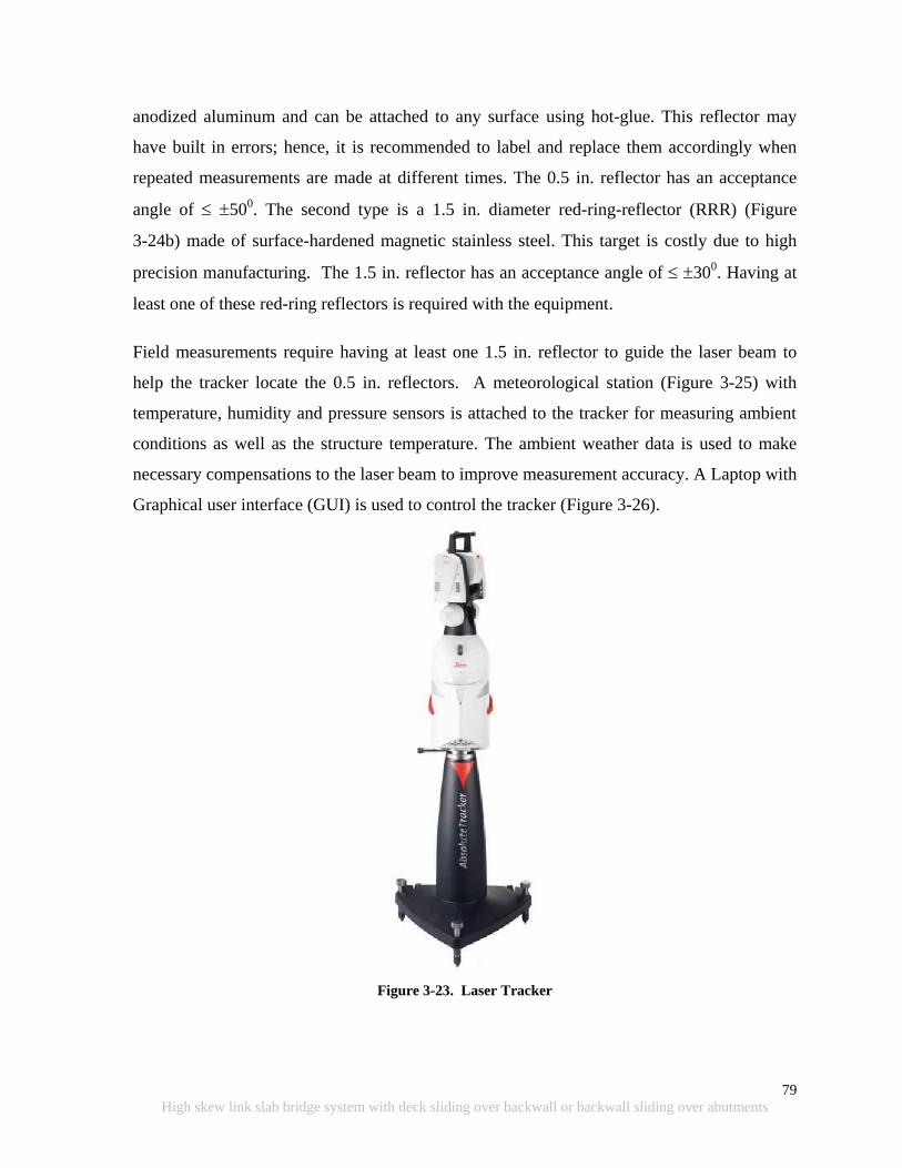
79
High skew link slab bridge system with deck sliding over backwall or backwall sliding over abutments
anodized aluminum and can be attached to any surface using hot-glue. This reflector may
have built in errors; hence, it is recommended to label and replace them accordingly when
repeated measurements are made at different times. The 0.5 in. reflector has an acceptance
angle of 500. The second type is a 1.5 in. diameter red-ring-reflector (RRR) (Figure
3-24b) made of surface-hardened magnetic stainless steel. This target is costly due to high
precision manufacturing. The 1.5 in. reflector has an acceptance angle of 300. Having at
least one of these red-ring reflectors is required with the equipment.
Field measurements require having at least one 1.5 in. reflector to guide the laser beam to
help the tracker locate the 0.5 in. reflectors. A meteorological station (Figure 3-25) with
temperature, humidity and pressure sensors is attached to the tracker for measuring ambient
conditions as well as the structure temperature. The ambient weather data is used to make
necessary compensations to the laser beam to improve measurement accuracy. A Laptop with
Graphical user interface (GUI) is used to control the tracker (Figure 3-26).
Figure 3-23. Laser Tracker
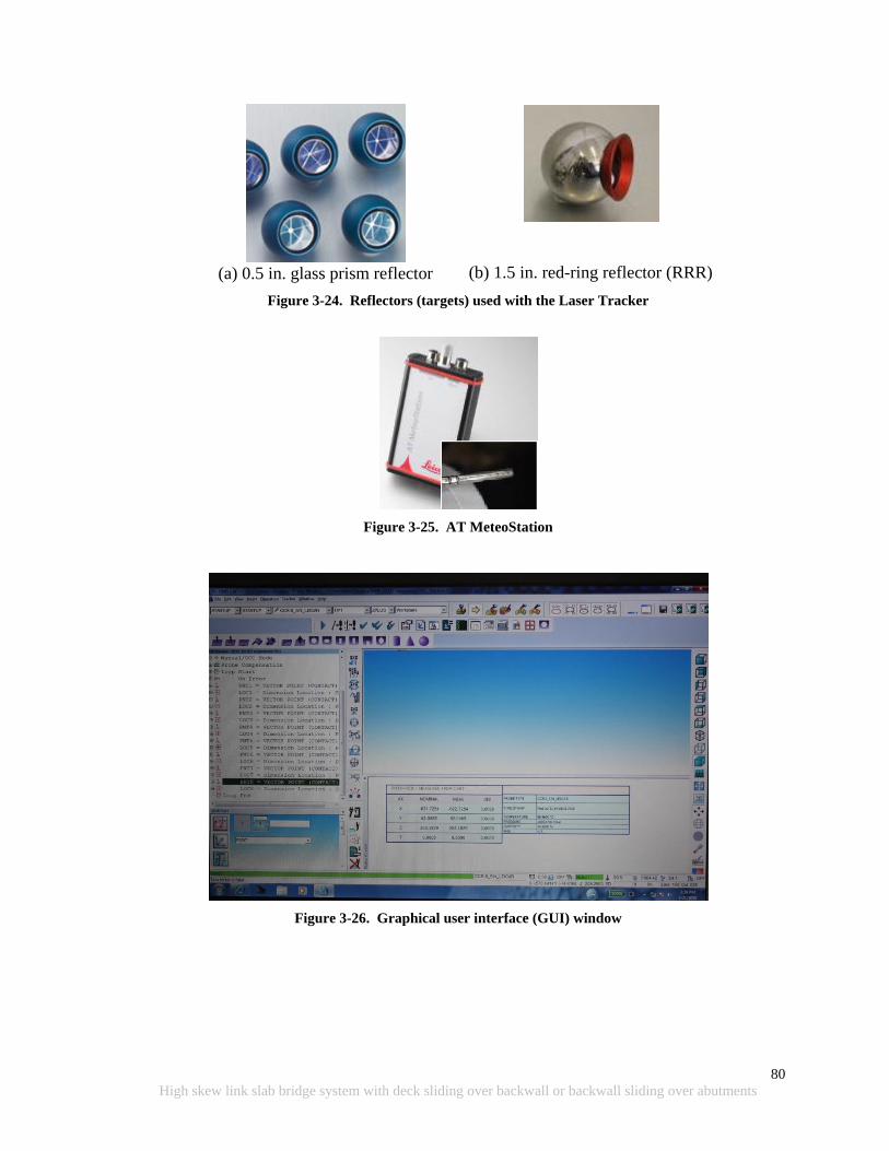
80
High skew link slab bridge system with deck sliding over backwall or backwall sliding over abutments
(a) 0.5 in. glass prism reflector
(b) 1.5 in. red-ring reflector (RRR)
Figure 3-24. Reflectors (targets) used with the Laser Tracker
Figure 3-25. AT MeteoStation
Figure 3-26. Graphical user interface (GUI) window

81
High skew link slab bridge system with deck sliding over backwall or backwall sliding over abutments
3.5.1.2 Target Locations and Placement
Monitoring the simple span bridge translation, under thermal load, relative to the abutments,
requires mounting targets at girder ends as well as on abutments. Measurement of bridge
translation under seasonal temperature changes requires mounting, removal, and remounting
of targets as needed and aligning the laser tracker with respect to several fixed references
(bench marks) every time the equipment is taken back to the field for making measurements.
Targets on the abutments are used as benchmarks. A coordinate system is defined using the
benchmarks so that the reference coordinate system is fixed for each measurement. Position
coordinates of girder end targets are measured with respect to the reference coordinate
system. Baseline measurements are taken after installing the targets. The other measurements
are taken after several weeks or months (as needed) with respect to the reference coordinate
system. The thermal deformations are calculated by subtracting the subsequent
measurements on girder ends from the baseline measurements. The assumption in this
measurement process is that the benchmark positions remain static during seasonal
temperature changes.
For mounting the targets, an aluminum base (part A) with a removable aluminum head (part
B) was fabricated (Figure 3-27a). Reflector (part C) is placed in the removable aluminum
head. The assembly is put together using a steel rod (part E) and a magnet (part D) attached
to the back of the aluminum base. The target holder base is permanently attached to the
abutments using 2-in. long cement screws (part F). At the girder end, they are mounted using
high strength epoxy glue upon grinding and cleaning the girder surface.
Target holders on this particular bridge were mounted on December 16, 2011, and the
ambient temperature was about 32 0F (Table 3-2). Cold weather conditions necessitate
heating girder ends to promote curing of epoxy. However, use of regular heat guns to heat
girder ends was not successful. Fortunately, having a magnet in the aluminum base helped
hold the base against steel girders without using any clamping device until epoxy cured. The
target is attached to the removable aluminum head using hot glue. All the removable
aluminum heads are labeled to make sure the same target is connected to the aluminum base
during the remounting process to control systemic errors. Following measurements part B is

82
High skew link slab bridge system with deck sliding over backwall or backwall sliding over abutments
removed, and a plastic cap is placed over the hole in the aluminum base (part A) to keep it
clean between measurements. Note that the plastic cap is mounted in an additional hole
drilled in the aluminum base to avoid losing it during the reflector mounting/remounting
process (Figure 3-27).
(a) Assembly
(b) Isometric view
(c) Top view
(d) Rear view
Figure 3-27. Accessories used for mounting girder end and abutment targets
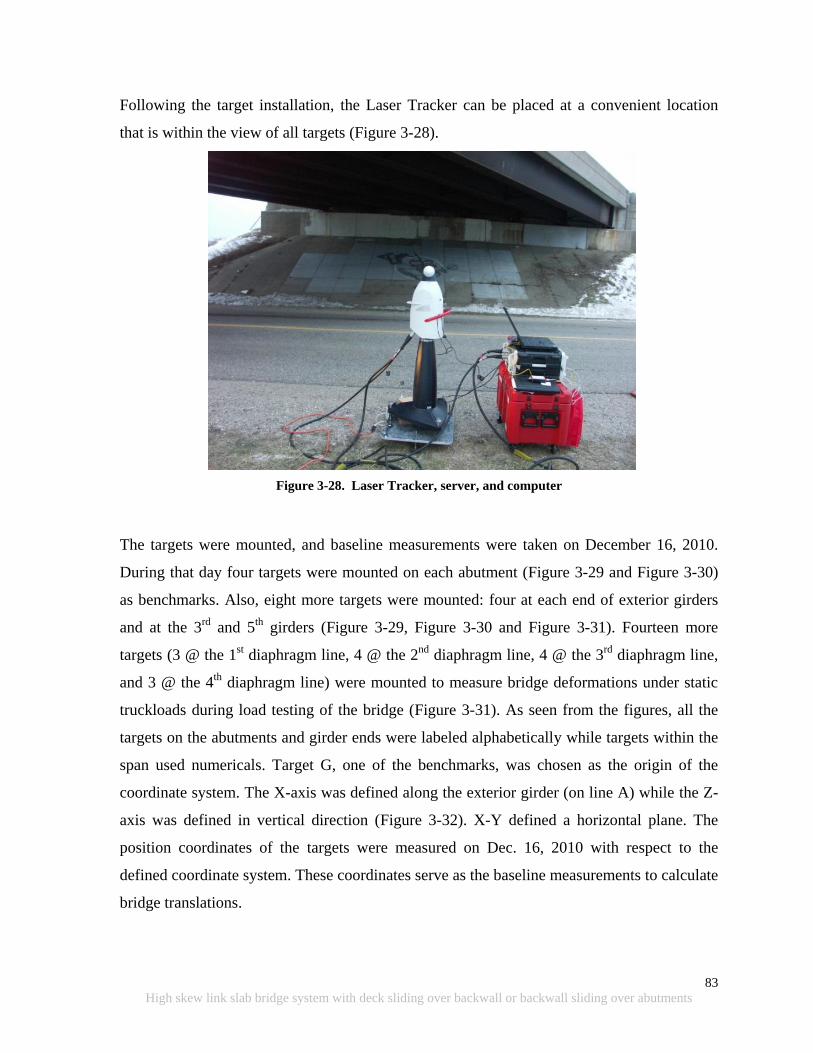
83
High skew link slab bridge system with deck sliding over backwall or backwall sliding over abutments
Following the target installation, the Laser Tracker can be placed at a convenient location
that is within the view of all targets (Figure 3-28).
Figure 3-28. Laser Tracker, server, and computer
The targets were mounted, and baseline measurements were taken on December 16, 2010.
During that day four targets were mounted on each abutment (Figure 3-29 and Figure 3-30)
as benchmarks. Also, eight more targets were mounted: four at each end of exterior girders
and at the 3rd
and 5th
girders (Figure 3-29, Figure 3-30 and Figure 3-31). Fourteen more
targets (3 @ the 1st diaphragm line, 4 @ the 2
nd diaphragm line, 4 @ the 3
rd diaphragm line,
and 3 @ the 4th
diaphragm line) were mounted to measure bridge deformations under static
truckloads during load testing of the bridge (Figure 3-31). As seen from the figures, all the
targets on the abutments and girder ends were labeled alphabetically while targets within the
span used numericals. Target G, one of the benchmarks, was chosen as the origin of the
coordinate system. The X-axis was defined along the exterior girder (on line A) while the Z-
axis was defined in vertical direction (Figure 3-32). X-Y defined a horizontal plane. The
position coordinates of the targets were measured on Dec. 16, 2010 with respect to the
defined coordinate system. These coordinates serve as the baseline measurements to calculate
bridge translations.
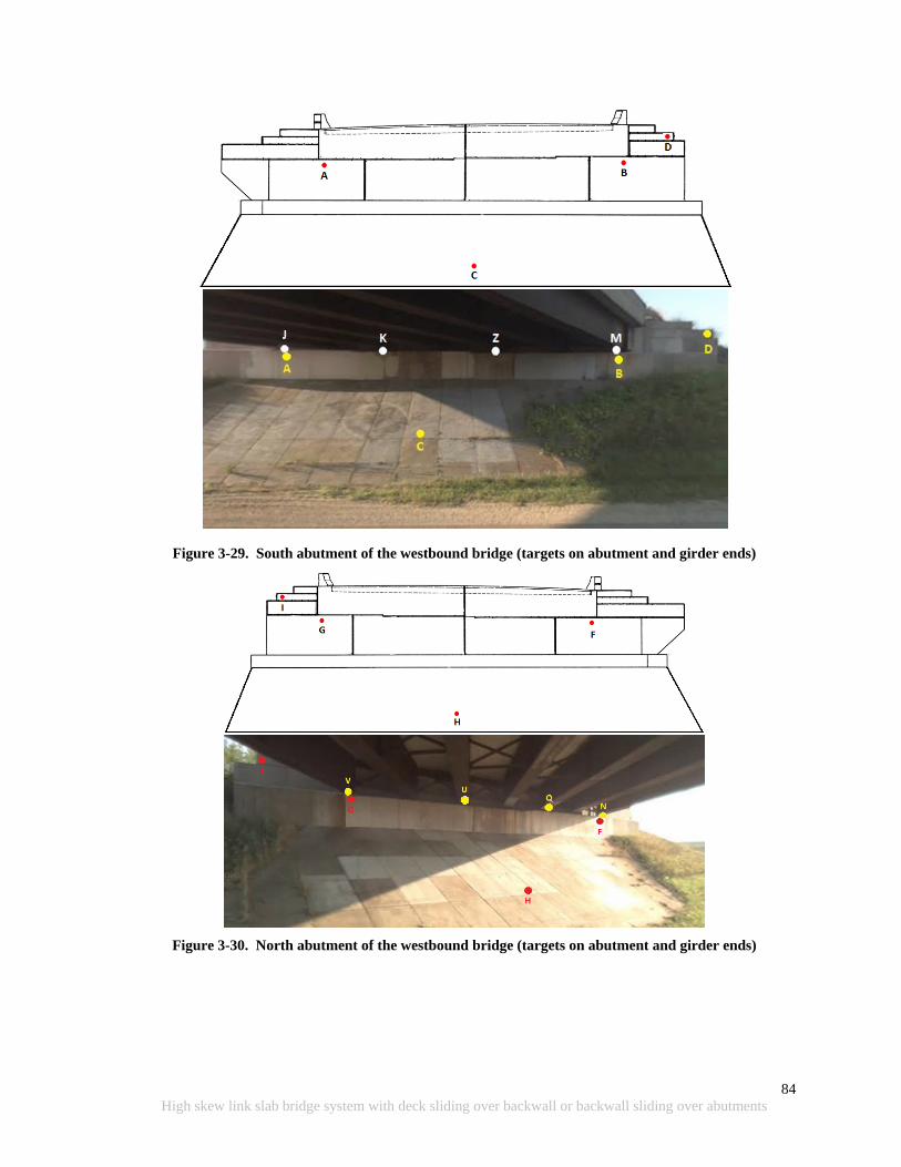
84
High skew link slab bridge system with deck sliding over backwall or backwall sliding over abutments
Figure 3-29. South abutment of the westbound bridge (targets on abutment and girder ends)
Figure 3-30. North abutment of the westbound bridge (targets on abutment and girder ends)

85
High skew link slab bridge system with deck sliding over backwall or backwall sliding over abutments
Figure 3-31. Target positions on girders
Figure 3-32. Coordinate system for Tracker measurements and target positions on north abutment and
girder ends
Table 3-2. Ambient Conditions at 2:30pm on December 16 2010
Temperature (0F) 32
Pressure (mmHg) 1181.91
Humidity (%) 51.7

86
High skew link slab bridge system with deck sliding over backwall or backwall sliding over abutments
Table 3-3. Target Position Coordinates – Baseline Measurements (Dec. 16, 2010)
Reflector Coordinates (in.)
X Y Z
A 892.5477 -472.3196 9.5949
B 1315.7579 4.0789 25.6603
C 965.7680 -166.5963 137.1540
D 1458.3465 119.4952 -18.3121
F -434.1164 -488.0187 -11.3823
G 0 0 0
H -78.4595 -313.7452 121.6880
I 42.8870 92.3908 -47.2806
J 884.1517 -486.8722 0.3646
K 1029.7024 -324.7426 5.3189
M 1310.6744 0.0678 16.0533
N -432.4237 -482.4572 -23.9580
Q -289.8550 -323.1314 -19.5721
U -148.4056 -161.3447 -14.2191
V -2.2858 2.6509 -9.2133
Z 1169.3041 -163.7294 10.6191
3.5.2 Bridge Deflection
3.5.2.1 Truck Configurations and Loading
The trucks, which were used for preliminary analysis, were not available on the day of load
testing; hence, two similar trucks, shown in Figure 3-33 (Truck 04-4009 and Truck 04-1659),
were used to serve the purpose. Four loading configurations similar to the preliminary
analysis were used to load the bridge (Figure 3-34 and Figure 3-35).
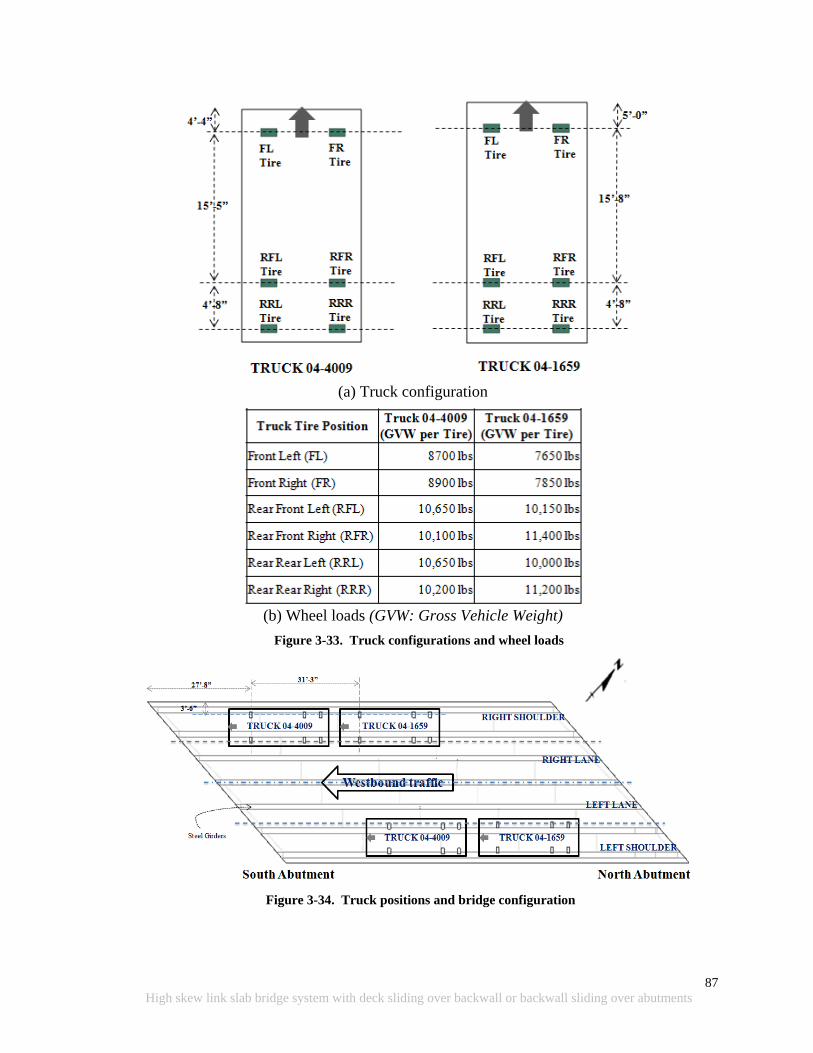
87
High skew link slab bridge system with deck sliding over backwall or backwall sliding over abutments
(a) Truck configuration
(b) Wheel loads (GVW: Gross Vehicle Weight)
Figure 3-33. Truck configurations and wheel loads
Figure 3-34. Truck positions and bridge configuration
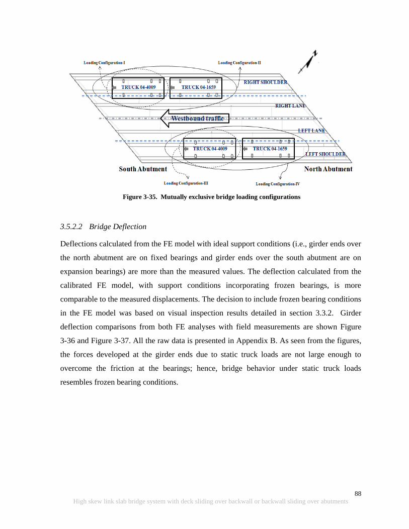
88
High skew link slab bridge system with deck sliding over backwall or backwall sliding over abutments
Figure 3-35. Mutually exclusive bridge loading configurations
3.5.2.2 Bridge Deflection
Deflections calculated from the FE model with ideal support conditions (i.e., girder ends over
the north abutment are on fixed bearings and girder ends over the south abutment are on
expansion bearings) are more than the measured values. The deflection calculated from the
calibrated FE model, with support conditions incorporating frozen bearings, is more
comparable to the measured displacements. The decision to include frozen bearing conditions
in the FE model was based on visual inspection results detailed in section 3.3.2. Girder
deflection comparisons from both FE analyses with field measurements are shown Figure
3-36 and Figure 3-37. All the raw data is presented in Appendix B. As seen from the figures,
the forces developed at the girder ends due to static truck loads are not large enough to
overcome the friction at the bearings; hence, bridge behavior under static truck loads
resembles frozen bearing conditions.
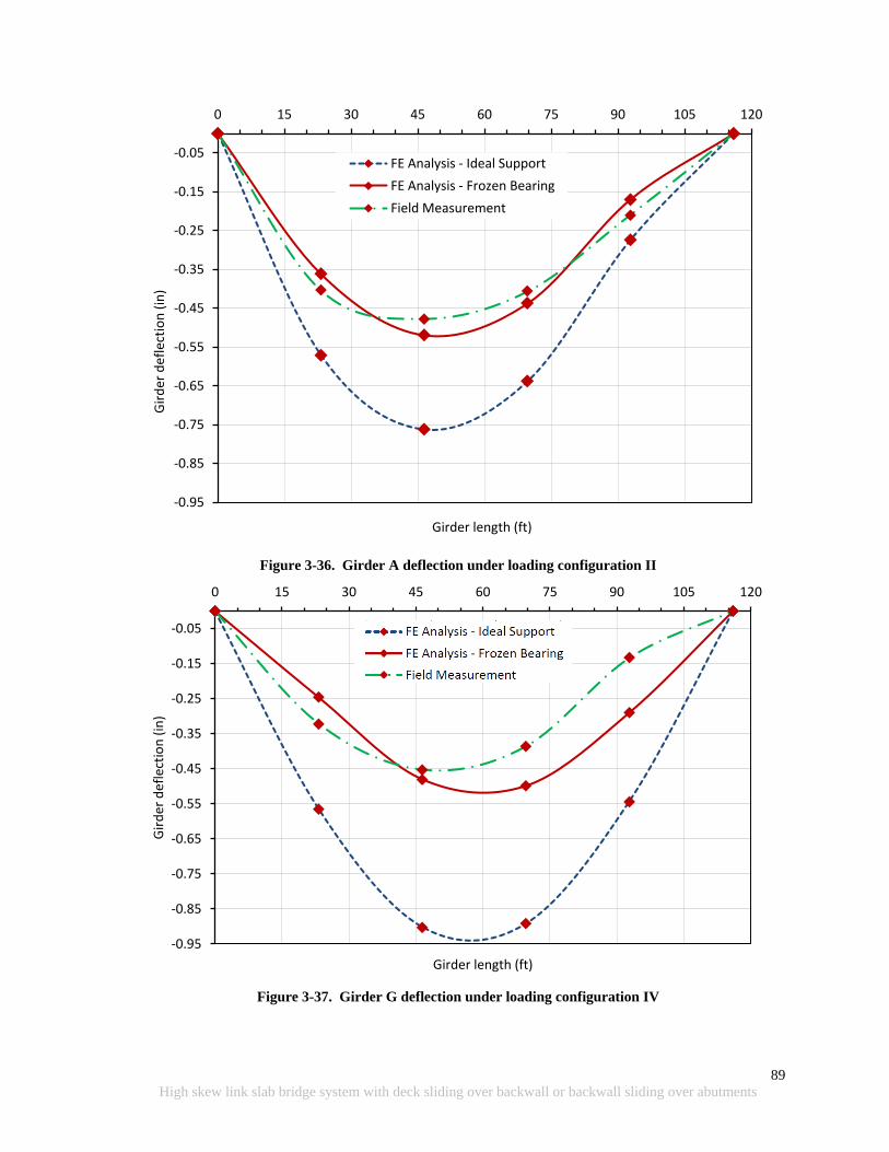
89
High skew link slab bridge system with deck sliding over backwall or backwall sliding over abutments
Figure 3-36. Girder A deflection under loading configuration II
Figure 3-37. Girder G deflection under loading configuration IV
-0.95
-0.85
-0.75
-0.65
-0.55
-0.45
-0.35
-0.25
-0.15
-0.05
0 15 30 45 60 75 90 105 120
Gir
der
def
lect
ion
(in
)
Girder length (ft)
FE Analysis - Ideal Support
FE Analysis - Frozen Bearing
Field Measurement
-0.95
-0.85
-0.75
-0.65
-0.55
-0.45
-0.35
-0.25
-0.15
-0.05
0 15 30 45 60 75 90 105 120
Gir
der
def
lect
ion
(in
)
Girder length (ft)
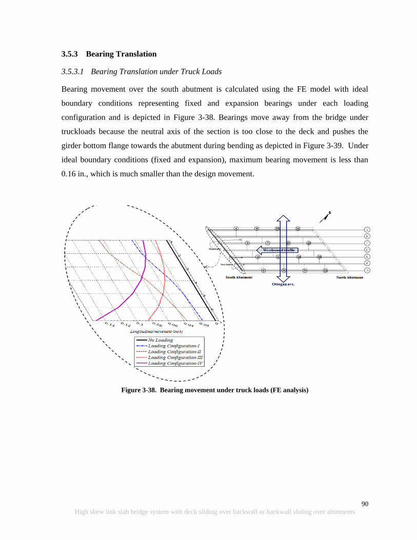
90
High skew link slab bridge system with deck sliding over backwall or backwall sliding over abutments
3.5.3 Bearing Translation
3.5.3.1 Bearing Translation under Truck Loads
Bearing movement over the south abutment is calculated using the FE model with ideal
boundary conditions representing fixed and expansion bearings under each loading
configuration and is depicted in Figure 3-38. Bearings move away from the bridge under
truckloads because the neutral axis of the section is too close to the deck and pushes the
girder bottom flange towards the abutment during bending as depicted in Figure 3-39. Under
ideal boundary conditions (fixed and expansion), maximum bearing movement is less than
0.16 in., which is much smaller than the design movement.
Figure 3-38. Bearing movement under truck loads (FE analysis)
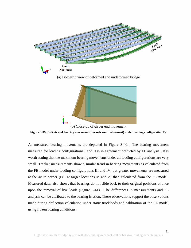
91
High skew link slab bridge system with deck sliding over backwall or backwall sliding over abutments
(a) Isometric view of deformed and undeformed bridge
(b) Close-up of girder end movement
Figure 3-39. 3-D view of bearing movement (towards south abutment) under loading configuration IV
As measured bearing movements are depicted in Figure 3-40. The bearing movement
measured for loading configurations I and II is in agreement predicted by FE analysis. It is
worth stating that the maximum bearing movements under all loading configurations are very
small. Tracker measurements show a similar trend in bearing movements as calculated from
the FE model under loading configurations III and IV; but greater movements are measured
at the acute corner (i.e., at target locations M and Z) than calculated from the FE model.
Measured data, also shows that bearings do not slide back to their original positions at once
upon the removal of live loads (Figure 3-41). The differences in measurements and FE
analysis can be attributed to the bearing friction. These observations support the observations
made during deflection calculation under static truckloads and calibration of the FE model
using frozen bearing conditions.
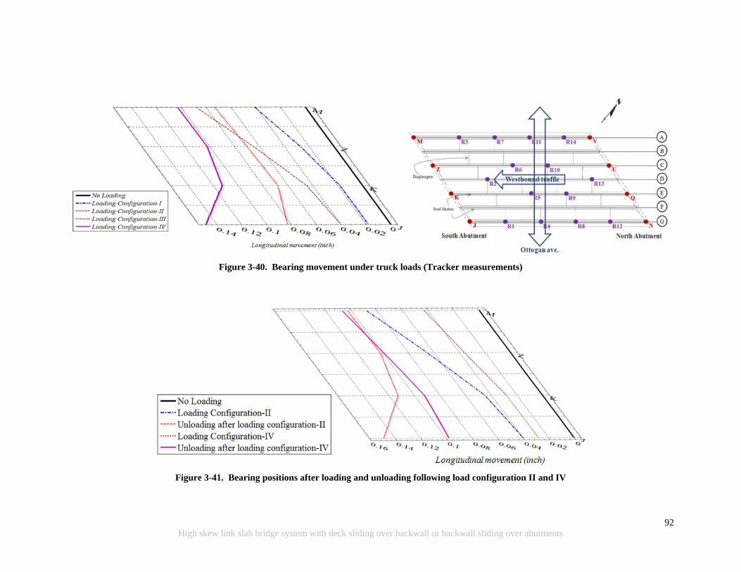
92
High skew link slab bridge system with deck sliding over backwall or backwall sliding over abutments
Figure 3-40. Bearing movement under truck loads (Tracker measurements)
Figure 3-41. Bearing positions after loading and unloading following load configuration II and IV
93
High skew link slab bridge system with deck sliding over backwall or backwall sliding over abutments
3.5.3.2 Bearing Translation under Thermal Loads
Calculated bearing translations with the FE model under uniform thermal expansion and
contraction as per AASHTO LRFD (2010) procedure B are given in Table 3-4 and shown in
Figure 3-42. Calculated maximum bearing translation due to expansion (∆T = 45 0F) and
contraction (∆T = 70 0F) occurs at the end of girder A. The bearing should allow 0.5 in.
expansion and 0.77 in. contraction movement under girder A, which gives a total movement
of 1.27 in. Though this movement is less than 1.875 in., shown in the bridge plans, the
position of the dowel bar may not have been near the center. Also, dowel bar damage
indicates lack of sufficient travel allowed for the bearing.
Tracker measurements were made to establish bearing travel over the south abutment under
thermal changes. The initial measurements were made on December 16, 2010 and repeated
on May 10, 2011 and again on July 13, 2011 (Figure 3-45). Ambient temperatures at the time
of measurements on December 16, May 10, and July 13 are 32 0F, 82.6
0F, and 67.3
0F.
Bridge expansion is not due to daily temperature changes; it is due to the average
temperature variation during a specific time period. Hence, maximum, minimum, and
average temperature variation at the site from December to August are obtained from a
nearby weather station, as shown in Figure 3-43 and Figure 3-44. According to Figure 3-44,
average temperatures at the site on December 16, May 10, and July 13, are 27.5 0F, 55
0F,
and 75 0F, respectively. Hence, temperature difference from December 16 to May 10 and
December 16 to July 13 are 25.7 0F and 47.5
0F, respectively. Calculated expansions at
bearing from December 16 to May 10 and from December 16 to July 13 are 0.3 in. and 0.52
in. According to the calculations, the bearing at location M, shown in Figure 3-45, is
expected to move 0.22 in. from May 10 to July 13. As shown in Figure 3-45, there was
hardly any movement at bearing M (< 0.01 in.). However, there is 0.05 in. movement at
bearing J, an indication that there is some rotation of the bridge deck about its normal axis.
The observations indicate that there is significant restraint for movement.
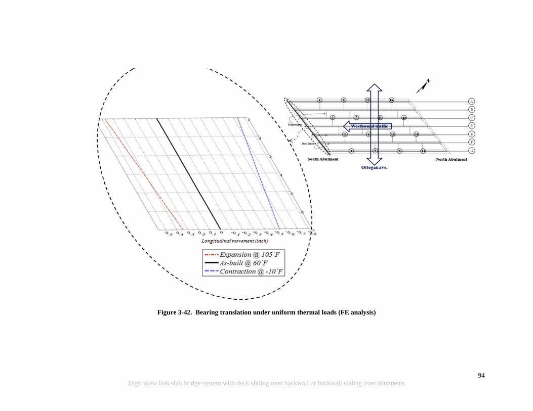
94
High skew link slab bridge system with deck sliding over backwall or backwall sliding over abutments
Figure 3-42. Bearing translation under uniform thermal loads (FE analysis)
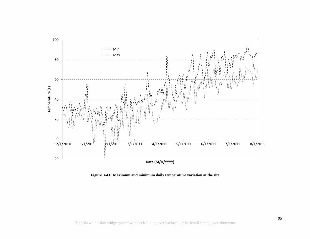
95
High skew link slab bridge system with deck sliding over backwall or backwall sliding over abutments
Figure 3-43. Maximum and minimum daily temperature variation at the site
-20
0
20
40
60
80
100
12/1/2010 1/1/2011 2/1/2011 3/1/2011 4/1/2011 5/1/2011 6/1/2011 7/1/2011 8/1/2011
Tem
pe
ratu
re (
F)
Date (M/D/YYYY)
Min
Max
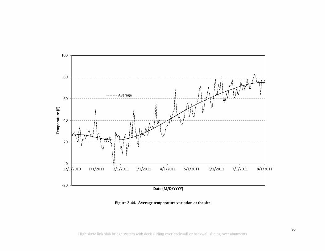
96
High skew link slab bridge system with deck sliding over backwall or backwall sliding over abutments
Figure 3-44. Average temperature variation at the site
-20
0
20
40
60
80
100
12/1/2010 1/1/2011 2/1/2011 3/1/2011 4/1/2011 5/1/2011 6/1/2011 7/1/2011 8/1/2011
Tem
pe
ratu
re (
F)
Date (M/D/YYYY)
Average

97
High skew link slab bridge system with deck sliding over backwall or backwall sliding over abutments
Table 3-4. Girder-End Translations over South Abutment under Uniform Temperature Loading
Girder
Label
FE Analysis (in.)+
Expansion (in.) at 105`0F
(∆T = 45`0F)
Contraction (in.) at -10`0F
(∆T = -70`0F)
A -0.474 0.737
B -0.452 0.703
C -0.430 0.669
D -0.408 0.635
E -0.387 0.602
F -0.366 0.569
G -0.344 0.535
+ Temperature at the time of construction is 60 0F
Figure 3-45. Bearing translation from Dec. 2010 to May 2011 and July 2011 (Tracker measurements)

98
High skew link slab bridge system with deck sliding over backwall or backwall sliding over abutments
3.6 SUMMARY
Bridge deflections and bearing translations were measured under static truck as well as
thermal loads. Measured girder deflections showed that girder end movements were
restrained due to friction. It is worth mentioning here that the bearing movements under
static truck loads were very small compared to allowance made at the design for thermal
expansion and contraction. The measured bearing movement under thermal expansion loads
from May to July indicates that the bearings are frozen and the in-plane twist of the deck
occurs due to bearing movement that is not expected at the design stage. Though there was
no damage to the superstructure and substructure of this 120 ft long single span bridge, this
behavior is critical when link slabs are implemented and the deck over the abutments is made
continuous. The observations highlight the importance of using durable bearings that are
capable of accommodating large deformation and a certain degree of rotation demands.
99
High skew link slab bridge system with deck sliding over backwall or backwall sliding over abutments
4 LINK SLAB ANALYSIS AND DESIGN GUIDELINES
4.1 OVERVIEW AND OBJECTIVES
The objective of this chapter is to present a detailed analysis of skew link slabs and moment
and force demand envelopes with respect to the skew angle at the link slab section directly
over the pier centerline. The analysis is performed for a specific bridge configuration (i.e.,
span length, width, and girder type), at various skew angles from 00 to 45
0. The finite
element (FE) models, for selected skew configurations, up to 450, are analyzed under loads
and configurations specified in AASHTO (2010). Further, the influence of different bearing
configurations on the link slab moment and force resultants are also investigated. Finally, the
design recommendations are developed for the utilization of links slabs in high skew bridges.
The design recommendations are developed based on literature review, analysis results, and
AASHTO (2010) requirements on strength and service load combinations.
4.2 CONTACT SIMULATION
The full-bridge FE models are developed using a detailed model of the link slab, deck, and
girders. Unfortunately when doing so, differences in the mesh densities prevent nodes on
different components from coinciding, thus preventing a way to “tie” the components
together. Fortunately, the contact surface options available in Abaqus/Standard version
6.10.1 are available to overcome this challenge (Abaqus 2010). Table 4-1 summarizes
contact surface option syntax used. For further information on the functions and use of each
option can be found in Romkema et al. (2010).

100
High skew link slab bridge system with deck sliding over backwall or backwall sliding over abutments
Table 4-1. ABAQUS Syntax for Various Contact Options
Row Contact Definitions ABAQUS Syntax
a General contact
(automatic option)
*CONTACT
*CONTACT INCLUSIONS, ALL EXTERIOR
b General contact
(user defined option)
*CONTACT
*CONTACT INCLUSIONS
surface_1, surface_2
c Contact pair with separation *CONTACT PAIR, INTERACTION=interaction1, ADJUST=nodes_to_adjust_to
slave_surface, master_surface
*SURFACE INTERACTION, NAME=interaction1
d Contact pair with tied option
*CONTACT PAIR, INTERACTION=interaction1, TIED, ADJUST=nodes_to_adjust_to
slave_surface, master_surface
*SURFACE INTERACTION, NAME=interaction1
*SURFACE BEHAVIOR, NO SEPARATION
e Contact pair with friction
*CONTACT PAIR, INTERACTION=interaction1
slave_surface, master_surface
*SURFACE INTERACTION, NAME = interaction1
*FRICTION
1.0, 0.0, 0.0, 0.0
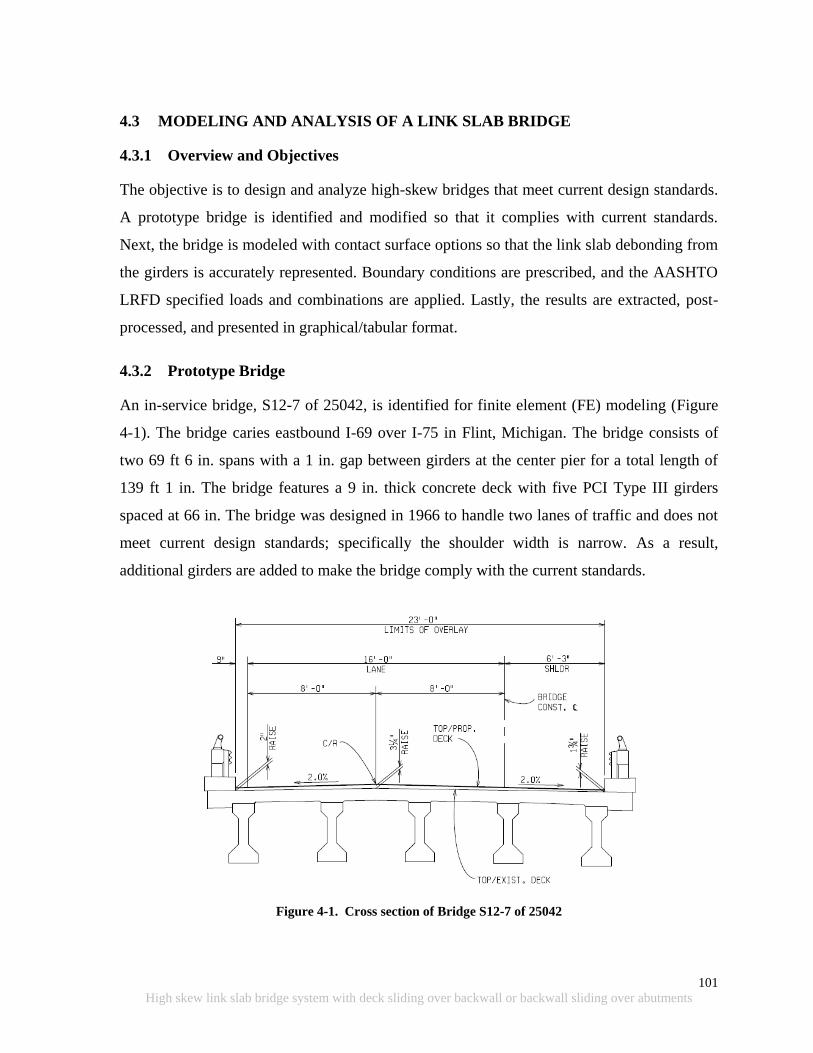
101
High skew link slab bridge system with deck sliding over backwall or backwall sliding over abutments
4.3 MODELING AND ANALYSIS OF A LINK SLAB BRIDGE
4.3.1 Overview and Objectives
The objective is to design and analyze high-skew bridges that meet current design standards.
A prototype bridge is identified and modified so that it complies with current standards.
Next, the bridge is modeled with contact surface options so that the link slab debonding from
the girders is accurately represented. Boundary conditions are prescribed, and the AASHTO
LRFD specified loads and combinations are applied. Lastly, the results are extracted, post-
processed, and presented in graphical/tabular format.
4.3.2 Prototype Bridge
An in-service bridge, S12-7 of 25042, is identified for finite element (FE) modeling (Figure
4-1). The bridge caries eastbound I-69 over I-75 in Flint, Michigan. The bridge consists of
two 69 ft 6 in. spans with a 1 in. gap between girders at the center pier for a total length of
139 ft 1 in. The bridge features a 9 in. thick concrete deck with five PCI Type III girders
spaced at 66 in. The bridge was designed in 1966 to handle two lanes of traffic and does not
meet current design standards; specifically the shoulder width is narrow. As a result,
additional girders are added to make the bridge comply with the current standards.
Figure 4-1. Cross section of Bridge S12-7 of 25042
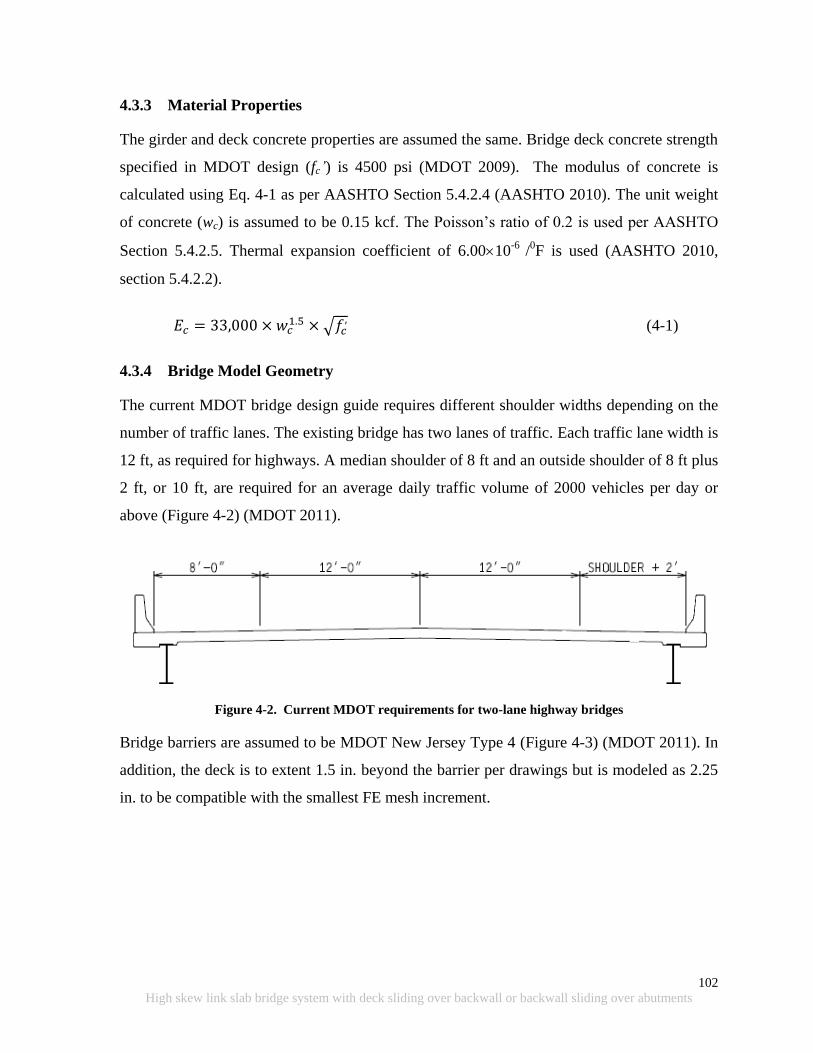
102
High skew link slab bridge system with deck sliding over backwall or backwall sliding over abutments
4.3.3 Material Properties
The girder and deck concrete properties are assumed the same. Bridge deck concrete strength
specified in MDOT design (fc’) is 4500 psi (MDOT 2009). The modulus of concrete is
calculated using Eq. 4-1 as per AASHTO Section 5.4.2.4 (AASHTO 2010). The unit weight
of concrete (wc) is assumed to be 0.15 kcf. The Poisson‟s ratio of 0.2 is used per AASHTO
Section 5.4.2.5. Thermal expansion coefficient of 6.0010-6
/0F is used (AASHTO 2010,
section 5.4.2.2).
(4-1)
4.3.4 Bridge Model Geometry
The current MDOT bridge design guide requires different shoulder widths depending on the
number of traffic lanes. The existing bridge has two lanes of traffic. Each traffic lane width is
12 ft, as required for highways. A median shoulder of 8 ft and an outside shoulder of 8 ft plus
2 ft, or 10 ft, are required for an average daily traffic volume of 2000 vehicles per day or
above (Figure 4-2) (MDOT 2011).
Figure 4-2. Current MDOT requirements for two-lane highway bridges
Bridge barriers are assumed to be MDOT New Jersey Type 4 (Figure 4-3) (MDOT 2011). In
addition, the deck is to extent 1.5 in. beyond the barrier per drawings but is modeled as 2.25
in. to be compatible with the smallest FE mesh increment.
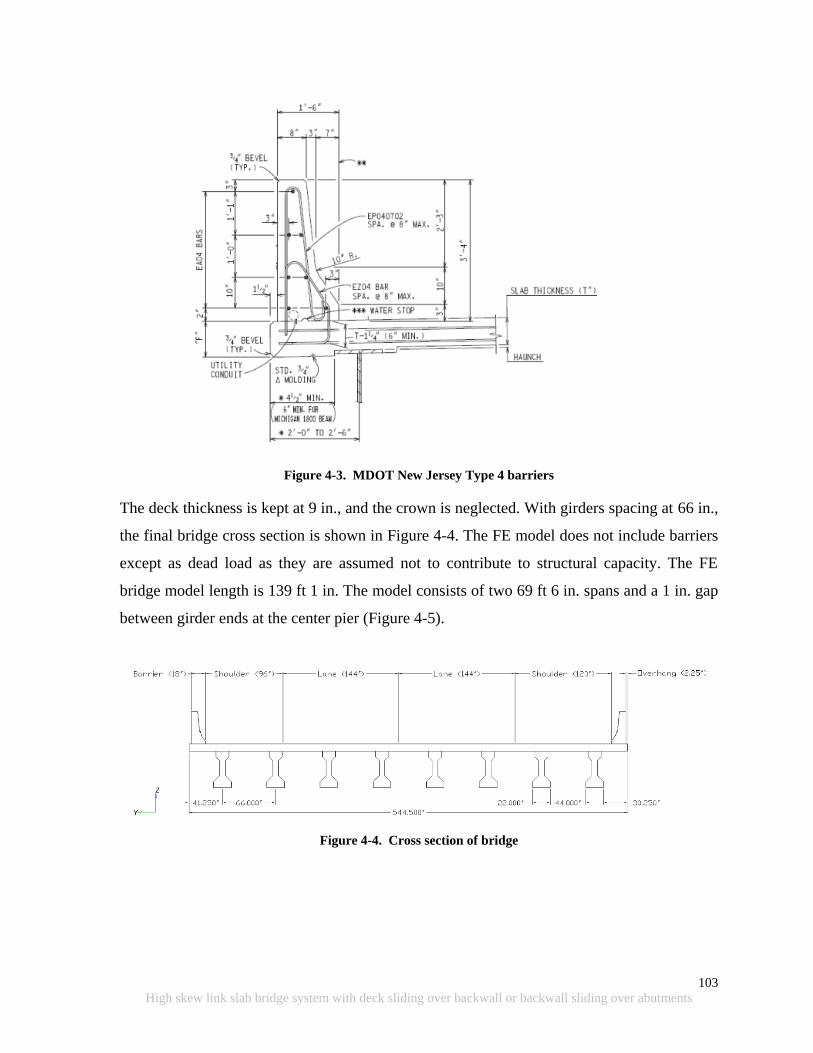
103
High skew link slab bridge system with deck sliding over backwall or backwall sliding over abutments
Figure 4-3. MDOT New Jersey Type 4 barriers
The deck thickness is kept at 9 in., and the crown is neglected. With girders spacing at 66 in.,
the final bridge cross section is shown in Figure 4-4. The FE model does not include barriers
except as dead load as they are assumed not to contribute to structural capacity. The FE
bridge model length is 139 ft 1 in. The model consists of two 69 ft 6 in. spans and a 1 in. gap
between girder ends at the center pier (Figure 4-5).
Figure 4-4. Cross section of bridge
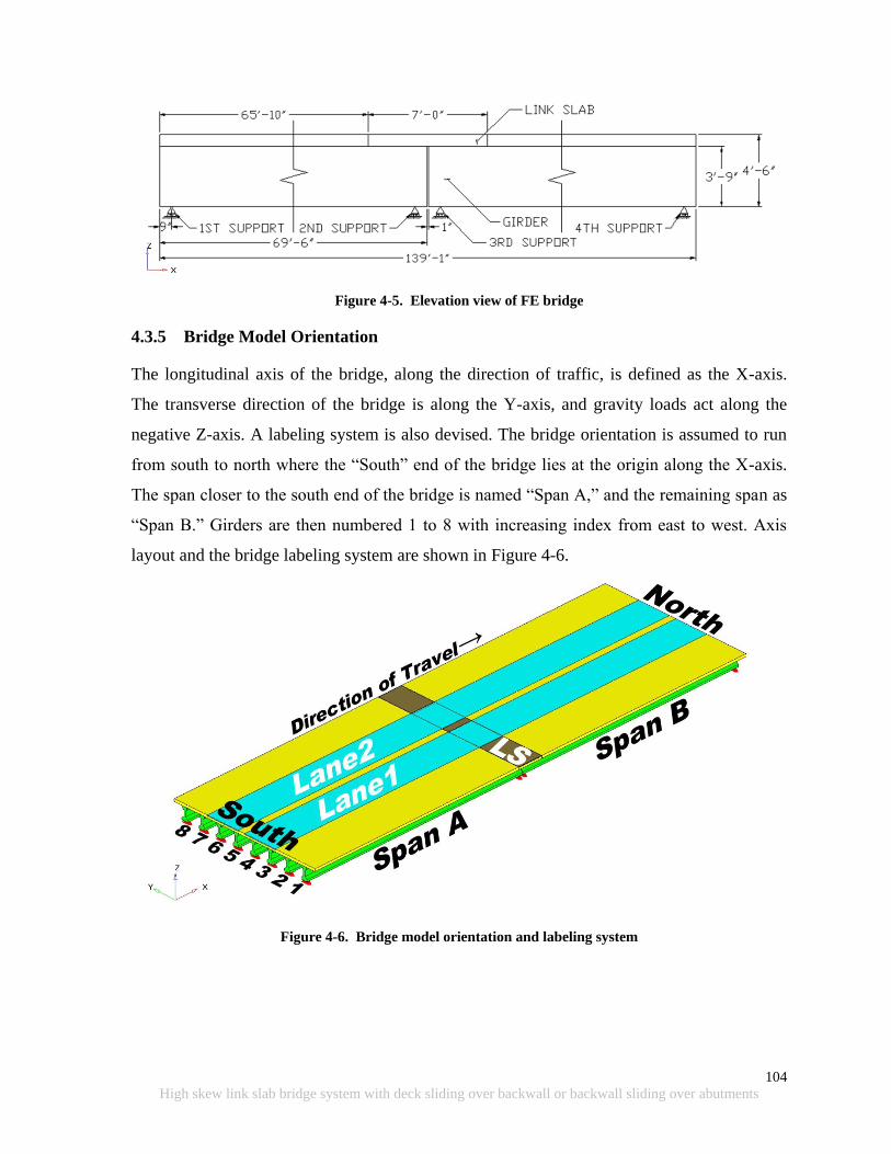
104
High skew link slab bridge system with deck sliding over backwall or backwall sliding over abutments
Figure 4-5. Elevation view of FE bridge
4.3.5 Bridge Model Orientation
The longitudinal axis of the bridge, along the direction of traffic, is defined as the X-axis.
The transverse direction of the bridge is along the Y-axis, and gravity loads act along the
negative Z-axis. A labeling system is also devised. The bridge orientation is assumed to run
from south to north where the “South” end of the bridge lies at the origin along the X-axis.
The span closer to the south end of the bridge is named “Span A,” and the remaining span as
“Span B.” Girders are then numbered 1 to 8 with increasing index from east to west. Axis
layout and the bridge labeling system are shown in Figure 4-6.
Figure 4-6. Bridge model orientation and labeling system

105
High skew link slab bridge system with deck sliding over backwall or backwall sliding over abutments
4.3.6 Link Slab Length
Ulku et al. (2009) recommends a link slab length of 5% of the span length. The link slab
length would then be 5% of 69 ft 6 in. multiplied by 2 spans plus 1 in. for the gap between
girders (i.e., 84.4 in.). The link slab length of 84 in. is used in the model for compatibility
with the FE mesh.
4.3.7 FE Discretization of the Bridge Model
4.3.7.1 Discretization of the Link Slab
Element width (along the y-axis) of 4.125 in. is selected for the deck and link slab. Mesh
needed to be refined at the link slab region for improved accuracy of the stresses. An element
height (along the z-axis) of 1.5 in. is used to allow for a node line along the mid-height of the
link slab. The length (along the x-axis) of the link slab elements must be determined in such a
way that a node line lies along the middle of the gap between the girder ends. This is to
allow calculation of the forces and moments along that middle section. Hence, an element
length of 2 in. is selected for the link slab region. Finally, the element length adjacent to the
deck is increased to 2.5 in. to satisfy the link slab length requirement. The resulting FE mesh
is shown in Figure 4-7 and Figure 4-8.
4.3.7.2 Discretization of the Deck
Uniform element width of 4.125 in. is chosen for the deck. Since stresses in the deck are not
of focus in this research, a coarser mesh with an element length of 10 in. is used for the
remainder of the deck outside the link slab region. A deck element thickness of 2.25 in is
used.
4.3.7.3 Discretization of the Girders
A coarser mesh with 10 in. long elements is chosen for the girders since accurate girder
stresses are not required. Mesh length near the bearings is reduced to 4.5 in. for accurate
placement of support restraints.
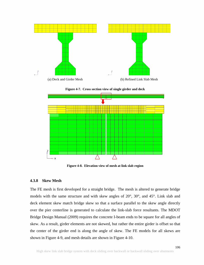
106
High skew link slab bridge system with deck sliding over backwall or backwall sliding over abutments
(a) Deck and Girder Mesh
(b) Refined Link Slab Mesh
Figure 4-7. Cross section view of single girder and deck
Figure 4-8. Elevation view of mesh at link slab region
4.3.8 Skew Mesh
The FE mesh is first developed for a straight bridge. The mesh is altered to generate bridge
models with the same structure and with skew angles of 20°, 30°, and 45°. Link slab and
deck element skew match bridge skew so that a surface parallel to the skew angle directly
over the pier centerline is generated to calculate the link-slab force resultants. The MDOT
Bridge Design Manual (2009) requires the concrete I-beam ends to be square for all angles of
skew. As a result, girder elements are not skewed, but rather the entire girder is offset so that
the center of the girder end is along the angle of skew. The FE models for all skews are
shown in Figure 4-9, and mesh details are shown in Figure 4-10.

107
High skew link slab bridge system with deck sliding over backwall or backwall sliding over abutments
(a) 0° Skew Bridge
(b) 20° Skew Bridge
(c) 30° Skew Bridge
(d) 45° Skew Bridge
Figure 4-9. Isometric view of bridge models
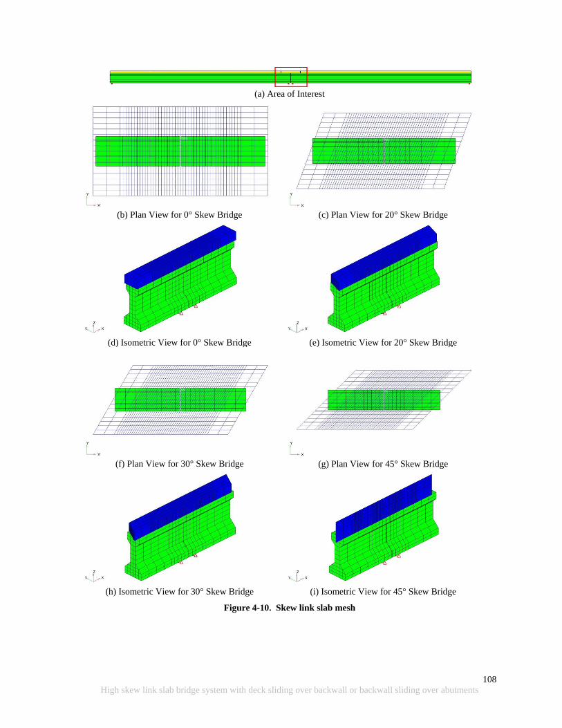
108
High skew link slab bridge system with deck sliding over backwall or backwall sliding over abutments
(a) Area of Interest
(b) Plan View for 0° Skew Bridge
(d) Isometric View for 0° Skew Bridge
(c) Plan View for 20° Skew Bridge
(e) Isometric View for 20° Skew Bridge
(f) Plan View for 30° Skew Bridge
(h) Isometric View for 30° Skew Bridge
(g) Plan View for 45° Skew Bridge
(i) Isometric View for 45° Skew Bridge
Figure 4-10. Skew link slab mesh
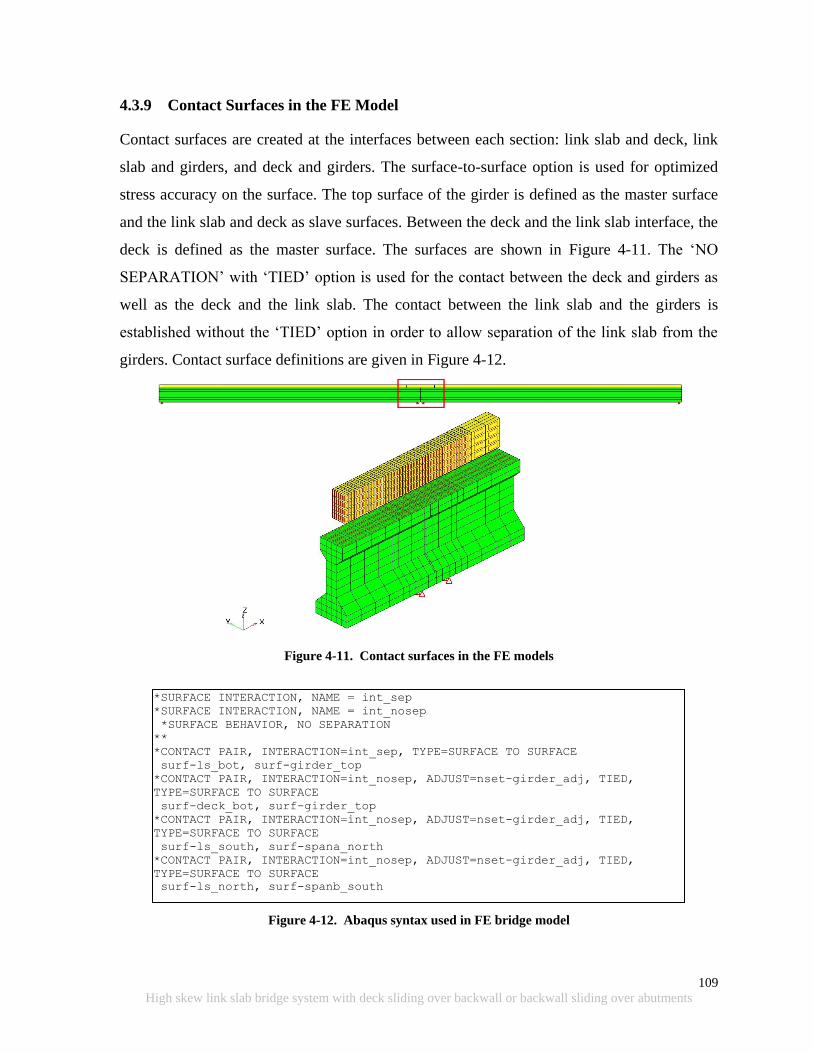
109
High skew link slab bridge system with deck sliding over backwall or backwall sliding over abutments
4.3.9 Contact Surfaces in the FE Model
Contact surfaces are created at the interfaces between each section: link slab and deck, link
slab and girders, and deck and girders. The surface-to-surface option is used for optimized
stress accuracy on the surface. The top surface of the girder is defined as the master surface
and the link slab and deck as slave surfaces. Between the deck and the link slab interface, the
deck is defined as the master surface. The surfaces are shown in Figure 4-11. The „NO
SEPARATION‟ with „TIED‟ option is used for the contact between the deck and girders as
well as the deck and the link slab. The contact between the link slab and the girders is
established without the „TIED‟ option in order to allow separation of the link slab from the
girders. Contact surface definitions are given in Figure 4-12.
Figure 4-11. Contact surfaces in the FE models
Figure 4-12. Abaqus syntax used in FE bridge model
*SURFACE INTERACTION, NAME = int_sep
*SURFACE INTERACTION, NAME = int_nosep
*SURFACE BEHAVIOR, NO SEPARATION
**
*CONTACT PAIR, INTERACTION=int_sep, TYPE=SURFACE TO SURFACE
surf-ls_bot, surf-girder_top
*CONTACT PAIR, INTERACTION=int_nosep, ADJUST=nset-girder_adj, TIED,
TYPE=SURFACE TO SURFACE
surf-deck_bot, surf-girder_top
*CONTACT PAIR, INTERACTION=int_nosep, ADJUST=nset-girder_adj, TIED,
TYPE=SURFACE TO SURFACE
surf-ls_south, surf-spana_north
*CONTACT PAIR, INTERACTION=int_nosep, ADJUST=nset-girder_adj, TIED,
TYPE=SURFACE TO SURFACE
surf-ls_north, surf-spanb_south

110
High skew link slab bridge system with deck sliding over backwall or backwall sliding over abutments
4.3.10 Boundary Conditions
Elastomeric bearing pads supporting girder ends allow movement and rotation of the girder
ends while providing limited restraint. Research conducted by Ulku et al. (2009) identified
that the difference between the restraining effects of the bearing pads and the ideal support
conditions on the link slab stresses are negligible. Accordingly, the ideal boundary conditions
are specified in the models.
Three different bearing configurations are investigated: hinge-roller-roller-roller (HRRR),
roller-hinge-hinge-roller (RHHR), and roller-roller-hinge-roller or roller-hinge-roller-roller
(RRHR or RHRR). The first support (roller or hinge) is the boundary condition over the first
abutment, the second support is the boundary condition over the pier, and so forth. This can
be visually seen in Figure 4-13 and Table 4-2.
Figure 4-13. Bearing configuration layout
Table 4-2. Bearing Configurations and Corresponding Support Conditions
Bearing
Configuration
1st Support
(Abutment)
2nd Support
(Pier)
3rd Support
(Pier)
4th Support
(Abutment)
HRRR H R R R
RHHR R H H R
RRHR (RHRR) R (R) R (H) H (R) R (R)
R = roller, H = hinge
4.3.11 Loads
The purpose here is to establish the design moment and axial force envelopes in the link slab
under various skew conditions. Five load cases are defined for this purpose. The first four
cases are truck and lane loads (i.e., AASHTO HL-93), and the last two cases are thermal
gradient loads. Deck and girder self weight effects on the link slab are often eliminated when
link slab placement is the last activity. In addition, barrier load effects are eliminated when
link slabs are implemented as part of a repair activity.
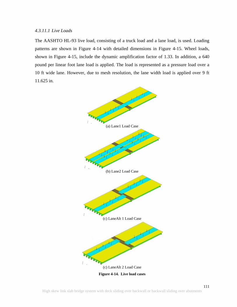
111
High skew link slab bridge system with deck sliding over backwall or backwall sliding over abutments
4.3.11.1 Live Loads
The AASHTO HL-93 live load, consisting of a truck load and a lane load, is used. Loading
patterns are shown in Figure 4-14 with detailed dimensions in Figure 4-15. Wheel loads,
shown in Figure 4-15, include the dynamic amplification factor of 1.33. In addition, a 640
pound per linear foot lane load is applied. The load is represented as a pressure load over a
10 ft wide lane. However, due to mesh resolution, the lane width load is applied over 9 ft
11.625 in.
(a) Lane1 Load Case
(b) Lane2 Load Case
(c) LaneAlt 1 Load Case
(c) LaneAlt 2 Load Case
Figure 4-14. Live load cases
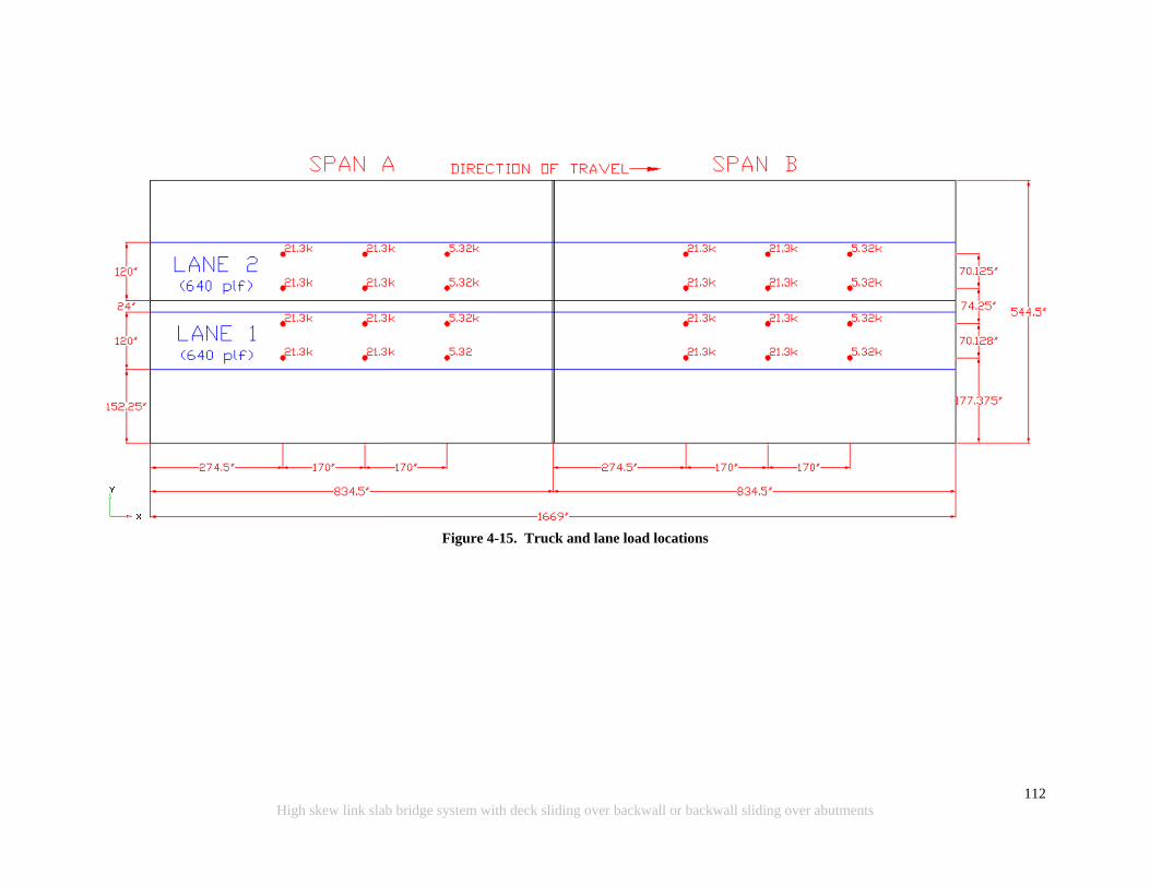
112
High skew link slab bridge system with deck sliding over backwall or backwall sliding over abutments
Figure 4-15. Truck and lane load locations

113
High skew link slab bridge system with deck sliding over backwall or backwall sliding over abutments
4.3.11.2 Temperature Gradient
The AASHTO (2010) Specification divides the United States into four zones based on solar
radiation. Each zone is assigned a temperature for the top of the deck and a temperature 4 in.
below the top of the deck. For Michigan, these are 41°F and 11°F for the positive
temperature gradient (PTG). The resulting temperature gradient is shown in Figure 4-16a.
The negative temperature gradient (NTG) values are obtained by multiplying the PTG values
by -0.30 for plain concrete and -0.20 for a deck with asphalt overlay. The value of -0.30 is
selected and the resultant temperature gradient profile is shown in Figure 4-16b.
(a) Positive temperature gradient (PTG)
(b) Negative temperature gradient (NTG)
Figure 4-16. Temperature gradient
Intentionally left blank

114
High skew link slab bridge system with deck sliding over backwall or backwall sliding over abutments
4.4 SIGN CONVENTION, MODEL VERIFICATION, AND RESULTS
4.4.1 Overview
The objective of analysis is to develop design recommendations for link slabs; hence, stresses
in the link slab are required. Envelopes of moments and forces that are needed for link slab
design are calculated from the link slab stresses. Abaqus allows for stresses to be averaged at
nodes so that they may be interpreted by the user. In addition, Abaqus has an option to
calculate forces and moments about a user-defined section. This option is utilized at the
center of the link slab where such a section is defined. The section provides the total force
and moment at the user-defined section along the center of the link slab. Finally, the reaction
forces are checked to assure FE model equilibrium.
4.4.2 Sign Convention
A sign convention is defined as shown in Figure 4-17. The longitudinal axis of the bridge lies
along X-axis. Link slab force in the X-direction is the axial force (Fx). Moment about the X-
axis is the torsion (Mxx). The transverse axis of the bridge is along the global Y-axis. Force in
the link slab in this direction is the transverse shear (Fy), and moment about this axis is the
bending moment (Myy). The vertical axis of this bridge is along the global Z-direction, the
opposite direction gravity acts. Force in this direction is the vertical shear (Fz), and moment
about this axis is the in-plane twist (Mzz). Force in tension has a negative sign. A negative
bending moment generates tension at the link slab top fiber.
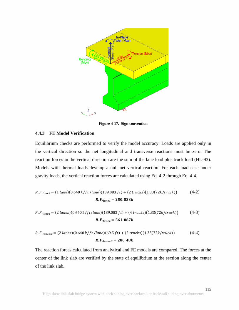
115
High skew link slab bridge system with deck sliding over backwall or backwall sliding over abutments
Figure 4-17. Sign convention
4.4.3 FE Model Verification
Equilibrium checks are performed to verify the model accuracy. Loads are applied only in
the vertical direction so the net longitudinal and transverse reactions must be zero. The
reaction forces in the vertical direction are the sum of the lane load plus truck load (HL-93).
Models with thermal loads develop a null net vertical reaction. For each load case under
gravity loads, the vertical reaction forces are calculated using Eq. 4-2 through Eq. 4-4.
(4-2)
(4-3)
(4-4)
The reaction forces calculated from analytical and FE models are compared. The forces at the
center of the link slab are verified by the state of equilibrium at the section along the center
of the link slab.

116
High skew link slab bridge system with deck sliding over backwall or backwall sliding over abutments
4.4.4 Results
Resultant forces and moments are calculated at a section defined as a surface. This feature is
utilized to calculate total force and moment acting at the user-defined surface along the
midspan of the link slab. Forces at a section are useful to draw general conclusions about the
effect of the angle of skew. In designing the section, a designer requires the effective force
and moment for a unit width. Both results are calculated and discussed below.
4.4.4.1 Cross Sectional Moments and Forces
Moments and forces are generated by the FE software about the local coordinate system of
the surface along the center of the link slab. Each angle of skew has a different orientation,
thus a local coordinate system of this surface. To have comparable forces for all skew cases,
the moments and forces about the local coordinate system are transformed into the global
coordinate system. The transpose of the transformation matrix between the local and global
systems is multiplied by vector of displacements, forces, moments, etc. in the local
coordinate system to obtain the values in relationship to the global coordinate system (Nelson
and McCormac2003).This relationship is given in Eq. 4-5.
(4-5)
where
{f} = Vector of forces in global coordinates
[T] = Transformation matrix
{f’} = Vector of force in local coordinates
As an example, a straight bridge with an HRRR boundary condition and Lane1 load case is
selected. Eq.4-6 shows the link slab moments in the local coordinate system. The first term in
the force vector shown in Eq.4-6 is the moment about the local x-axis (torsion), the second is
about the local y-axis (bending moment), and the third is about the local z-axis (in-plane
twist). The transformation matrix is shown in Eq. 4-7. The first row of the transformation
matrix is the direction cosines of local x-axis with respect to the global coordinates.
Similarly, row 2 and row 3 represent direction cosines of local axes y and z.

117
High skew link slab bridge system with deck sliding over backwall or backwall sliding over abutments
From here, the transformation matrix is transposed and multiplied by the moments about the
local coordinate system as shown in Eq. 4-8. Lastly, the moments about the global coordinate
system are shown in Eq. 4-9. This process is performed for all the models so that the results
allow direct comparison of forces and moments in all cases of changing skew.
(4-6)
(4-7)
(4-8)
(4-9)
The total sectional moments and forces, with respect to the global coordinate system, are
shown graphically in Figure 4-18 through Figure 4-29 with respect to each load case.
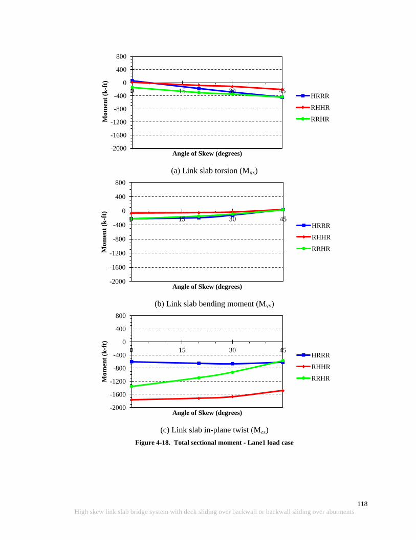
118
High skew link slab bridge system with deck sliding over backwall or backwall sliding over abutments
(a) Link slab torsion (Mxx)
(b) Link slab bending moment (Myy)
(c) Link slab in-plane twist (Mzz)
Figure 4-18. Total sectional moment - Lane1 load case
-2000
-1600
-1200
-800
-400
0
400
800
0 15 30 45
Mo
men
t (k
-ft)
Angle of Skew (degrees)
HRRR
RHHR
RRHR
-2000
-1600
-1200
-800
-400
0
400
800
0 15 30 45
Mo
men
t (k
-ft)
Angle of Skew (degrees)
HRRR
RHHR
RRHR
-2000
-1600
-1200
-800
-400
0
400
800
0 15 30 45
Mo
men
t (k
-ft)
Angle of Skew (degrees)
HRRR
RHHR
RRHR
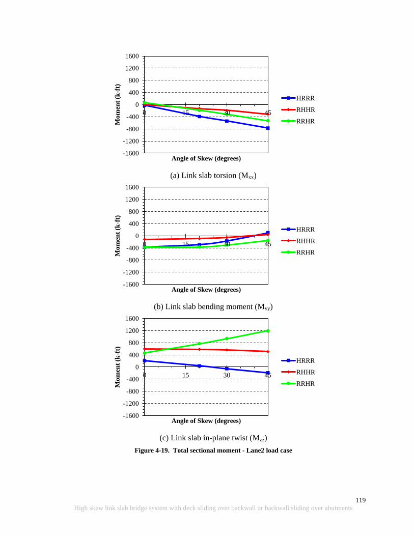
119
High skew link slab bridge system with deck sliding over backwall or backwall sliding over abutments
(a) Link slab torsion (Mxx)
(b) Link slab bending moment (Myy)
(c) Link slab in-plane twist (Mzz)
Figure 4-19. Total sectional moment - Lane2 load case
-1600
-1200
-800
-400
0
400
800
1200
1600
0 15 30 45 M
om
ent
(k-f
t)
Angle of Skew (degrees)
HRRR
RHHR
RRHR
-1600
-1200
-800
-400
0
400
800
1200
1600
0 15 30 45
Mo
men
t (k
-ft)
Angle of Skew (degrees)
HRRR
RHHR
RRHR
-1600
-1200
-800
-400
0
400
800
1200
1600
0 15 30 45
Mo
men
t (k
-ft)
Angle of Skew (degrees)
HRRR
RHHR
RRHR
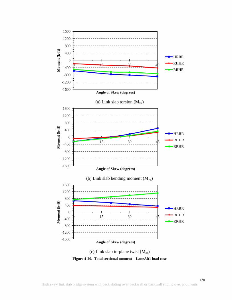
120
High skew link slab bridge system with deck sliding over backwall or backwall sliding over abutments
(a) Link slab torsion (Mxx)
(b) Link slab bending moment (Myy)
(c) Link slab in-plane twist (Mzz)
Figure 4-20. Total sectional moment – LaneAlt1 load case
-1600
-1200
-800
-400
0
400
800
1200
1600
0 15 30 45
Mo
men
t (k
-ft)
Angle of Skew (degrees)
HRRR
RHHR
RRHR
-1600
-1200
-800
-400
0
400
800
1200
1600
0 15 30 45
Mo
men
t (k
-ft)
Angle of Skew (degrees)
HRRR
RHHR
RRHR
-1600
-1200
-800
-400
0
400
800
1200
1600
0 15 30 45
Mo
men
t (k
-ft)
Angle of Skew (degrees)
HRRR
RHHR
RRHR
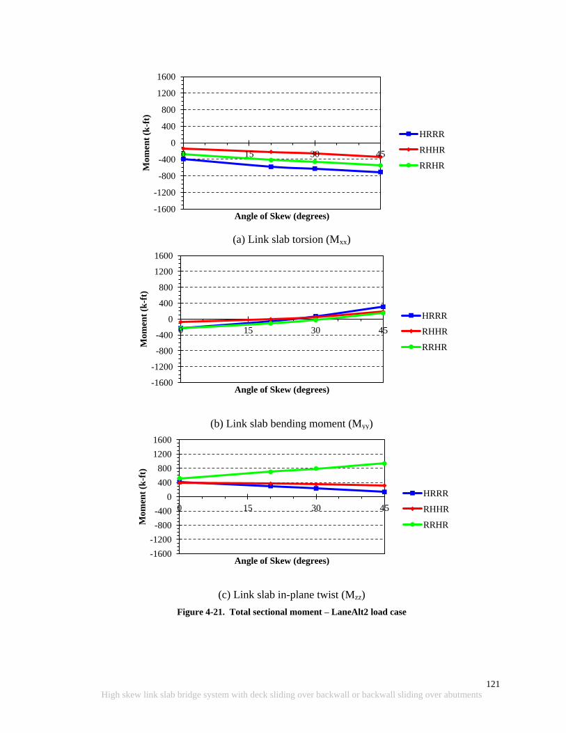
121
High skew link slab bridge system with deck sliding over backwall or backwall sliding over abutments
(a) Link slab torsion (Mxx)
(b) Link slab bending moment (Myy)
(c) Link slab in-plane twist (Mzz)
Figure 4-21. Total sectional moment – LaneAlt2 load case
-1600
-1200
-800
-400
0
400
800
1200
1600
0 15 30 45 M
om
ent
(k-f
t)
Angle of Skew (degrees)
HRRR
RHHR
RRHR
-1600
-1200
-800
-400
0
400
800
1200
1600
0 15 30 45
Mo
men
t (k
-ft)
Angle of Skew (degrees)
HRRR
RHHR
RRHR
-1600
-1200
-800
-400
0
400
800
1200
1600
0 15 30 45
Mo
men
t (k
-ft)
Angle of Skew (degrees)
HRRR
RHHR
RRHR
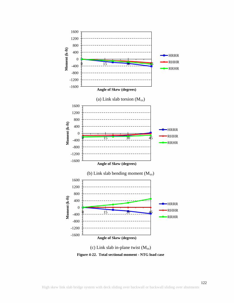
122
High skew link slab bridge system with deck sliding over backwall or backwall sliding over abutments
(a) Link slab torsion (Mxx)
(b) Link slab bending moment (Myy)
(c) Link slab in-plane twist (Mzz)
Figure 4-22. Total sectional moment - NTG load case
-1600
-1200
-800
-400
0
400
800
1200
1600
0 15 30 45 M
om
ent
(k-f
t)
Angle of Skew (degrees)
HRRR
RHHR
RRHR
-1600
-1200
-800
-400
0
400
800
1200
1600
0 15 30 45
Mo
men
t (k
-ft)
Angle of Skew (degrees)
HRRR
RHHR
RRHR
-1600
-1200
-800
-400
0
400
800
1200
1600
0 15 30 45
Mo
men
t (k
-ft)
Angle of Skew (degrees)
HRRR
RHHR
RRHR
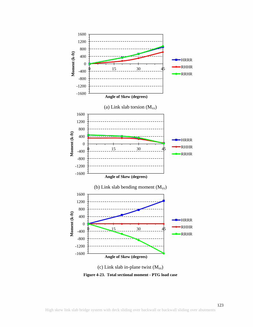
123
High skew link slab bridge system with deck sliding over backwall or backwall sliding over abutments
(a) Link slab torsion (Mxx)
(b) Link slab bending moment (Myy)
(c) Link slab in-plane twist (Mzz)
Figure 4-23. Total sectional moment - PTG load case
-1600
-1200
-800
-400
0
400
800
1200
1600
0 15 30 45 M
om
ent
(k-f
t)
Angle of Skew (degrees)
HRRR
RHHR
RRHR
-1600
-1200
-800
-400
0
400
800
1200
1600
0 15 30 45
Mo
men
t (k
-ft)
Angle of Skew (degrees)
HRRR
RHHR
RRHR
-1600
-1200
-800
-400
0
400
800
1200
1600
0 15 30 45
Mo
men
t (k
-ft)
Angle of Skew (degrees)
HRRR
RHHR
RRHR
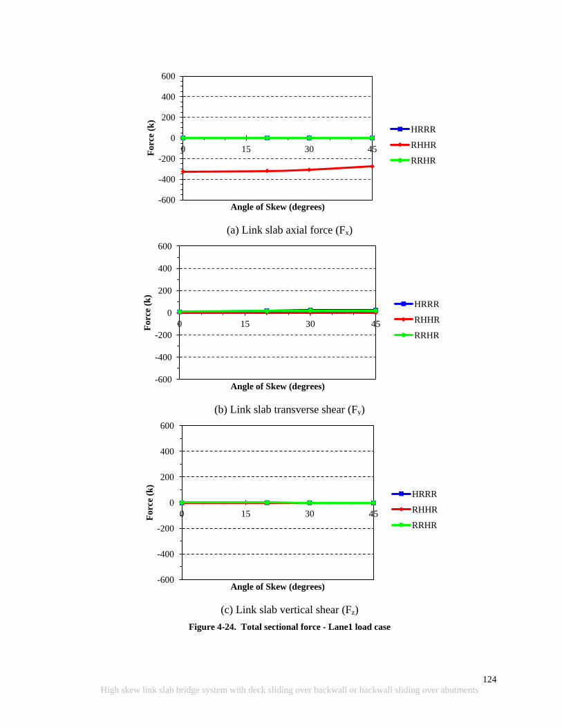
124
High skew link slab bridge system with deck sliding over backwall or backwall sliding over abutments
(a) Link slab axial force (Fx)
(b) Link slab transverse shear (Fy)
(c) Link slab vertical shear (Fz)
Figure 4-24. Total sectional force - Lane1 load case
-600
-400
-200
0
200
400
600
0 15 30 45 Fo
rce
(k)
Angle of Skew (degrees)
HRRR
RHHR
RRHR
-600
-400
-200
0
200
400
600
0 15 30 45 Fo
rce
(k)
Angle of Skew (degrees)
HRRR
RHHR
RRHR
-600
-400
-200
0
200
400
600
0 15 30 45 Forc
e (k
)
Angle of Skew (degrees)
HRRR
RHHR
RRHR
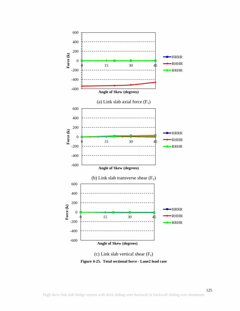
125
High skew link slab bridge system with deck sliding over backwall or backwall sliding over abutments
(a) Link slab axial force (Fx)
(b) Link slab transverse shear (Fy)
(c) Link slab vertical shear (Fz)
Figure 4-25. Total sectional force - Lane2 load case
-600
-400
-200
0
200
400
600
0 15 30 45 Fo
rce
(k)
Angle of Skew (degrees)
HRRR
RHHR
RRHR
-600
-400
-200
0
200
400
600
0 15 30 45 Fo
rce
(k)
Angle of Skew (degrees)
HRRR
RHHR
RRHR
-600
-400
-200
0
200
400
600
0 15 30 45 Forc
e (k
)
Angle of Skew (degrees)
HRRR
RHHR
RRHR
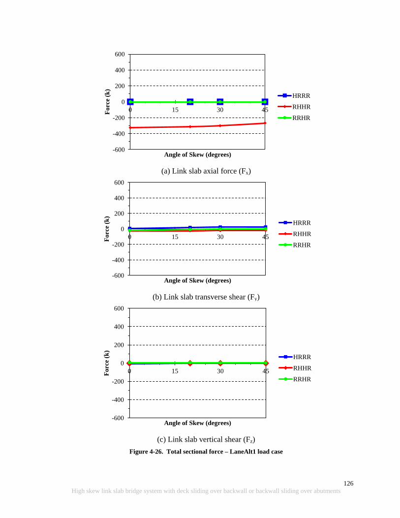
126
High skew link slab bridge system with deck sliding over backwall or backwall sliding over abutments
(a) Link slab axial force (Fx)
(b) Link slab transverse shear (Fy)
(c) Link slab vertical shear (Fz)
Figure 4-26. Total sectional force – LaneAlt1 load case
-600
-400
-200
0
200
400
600
0 15 30 45 Fo
rce
(k)
Angle of Skew (degrees)
HRRR
RHHR
RRHR
-600
-400
-200
0
200
400
600
0 15 30 45 Fo
rce
(k)
Angle of Skew (degrees)
HRRR
RHHR
RRHR
-600
-400
-200
0
200
400
600
0 15 30 45 Forc
e (k
)
Angle of Skew (degrees)
HRRR
RHHR
RRHR

127
High skew link slab bridge system with deck sliding over backwall or backwall sliding over abutments
(a) Link slab axial force (Fx)
(b) Link slab transverse shear (Fy)
(c) Link slab vertical shear (Fz)
Figure 4-27. Total sectional force – LaneAlt2 load case
-600
-400
-200
0
200
400
600
0 15 30 45
Fo
rce
(Kip
s)
Angle of Skew (degrees)
HRRR
RHHR
RRHR
-600
-400
-200
0
200
400
600
0 15 30 45
Fo
rce
(Kip
s)
Angle of Skew (degrees)
HRRR
RHHR
RRHR
-600
-400
-200
0
200
400
600
0 15 30 45
Forc
e (K
ips)
Angle of Skew (degrees)
HRRR
RHHR
RRHR
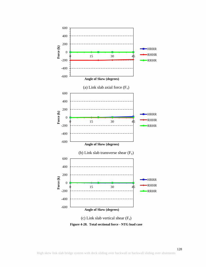
128
High skew link slab bridge system with deck sliding over backwall or backwall sliding over abutments
(a) Link slab axial force (Fx)
(b) Link slab transverse shear (Fy)
(c) Link slab vertical shear (Fz)
Figure 4-28. Total sectional force - NTG load case
-600
-400
-200
0
200
400
600
0 15 30 45 Fo
rce
(k)
Angle of Skew (degrees)
HRRR
RHHR
RRHR
-600
-400
-200
0
200
400
600
0 15 30 45 Fo
rce
(k)
Angle of Skew (degrees)
HRRR
RHHR
RRHR
-600
-400
-200
0
200
400
600
0 15 30 45 Forc
e (k
)
Angle of Skew (degrees)
HRRR
RHHR
RRHR
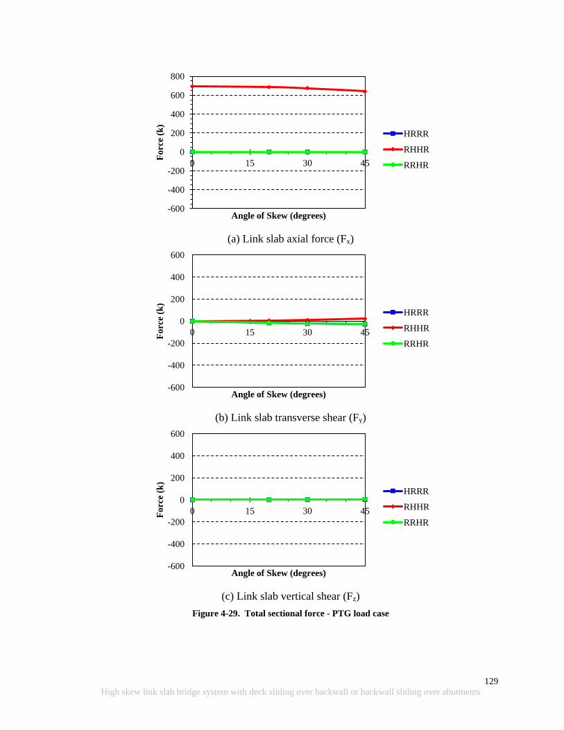
129
High skew link slab bridge system with deck sliding over backwall or backwall sliding over abutments
(a) Link slab axial force (Fx)
(b) Link slab transverse shear (Fy)
(c) Link slab vertical shear (Fz)
Figure 4-29. Total sectional force - PTG load case
-600
-400
-200
0
200
400
600
800
0 15 30 45 F
orc
e (k
)
Angle of Skew (degrees)
HRRR
RHHR
RRHR
-600
-400
-200
0
200
400
600
0 15 30 45 Fo
rce
(k)
Angle of Skew (degrees)
HRRR
RHHR
RRHR
-600
-400
-200
0
200
400
600
0 15 30 45 Forc
e (k
)
Angle of Skew (degrees)
HRRR
RHHR
RRHR

130
High skew link slab bridge system with deck sliding over backwall or backwall sliding over abutments
Table 4-3 presents a summary of the total sectional moments and forces shown in Figure
4-18 through Figure 4-29. From Table 4-3, the following general conclusions are derived.
1) The torsion (Mxx) magnitude in the link slab increases as the angle of skew increases
for all load cases and boundary conditions. The RHHR boundary condition generates
the lowest torsion.
2) The bending moment, under the LaneAlt 1 and 2 load cases, reverses from negative to
positive. The bending moment magnitude decreases as the angle of skew increases in
load cases Lane1 and Lane2 as well as both positive temperature gradient (PTG) and
negative temperature gradient (NTG). The lowest bending moment magnitude is
developed with RHHR boundary condition while magnitudes are the same for HRRR
and RRHR boundary conditions.
3) The link slab with an RHHR support configuration does not develop in-plane twist
(Mzz) under PTG or NTG, irrespective of bridge skew. Twist remains constant under
live loads with RHHR support configuration. Under PTG or NTG, significant twist is
developed with HRRR and RRHR support configurations. Link slab twist shows
mixed behavior under live loads with HRRR or RRHR support configurations.
4) Axial force in the link slab slightly decreases under all load cases with increasing
skew and with RHHR boundary conditions. The largest axial force is developed
under the PTG.
5) Axial force is zero under HRRR and RRHR boundary conditions. Vertical or
transverse shear forces developed in the link slab are insignificant irrespective of
loads, support configurations, or skew.
The above conclusions are based on the moments and forces developed at the entire cross-
section of the link slab. These moments and forces are helpful in understanding the link slab
behavior with changing skew. Design forces and moments will be calculated combining
forces and moments within an effective width of a link slab. Hence, such forces and moments
are calculated and presented in the following section.
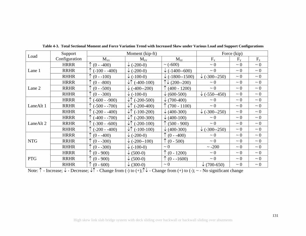
131
High skew link slab bridge system with deck sliding over backwall or backwall sliding over abutments
Table 4-3. Total Sectional Moment and Force Variation Trend with Increased Skew under Various Load and Support Configurations
Load Support
Configuration
Moment (kip-ft) Force (kip)
Mxx Myy Mzz Fx Fy Fz
Lane 1
HRRR (0 - -400) (-200-0) ~ (-600) ~ 0 ~ 0 ~ 0
RRHR (-100 - -400) (-200-0) (-1400--600) ~ 0 ~ 0 ~ 0
RHHR (0 - -100) (-100-0) (-1800--1500) (-300--250) ~ 0 ~ 0
Lane 2
HRRR (0 - -800) (-400-100) (200--200) ~ 0 ~ 0 ~ 0
RRHR (0 - -500) (-400--200) (400 - 1200) ~ 0 ~ 0 ~ 0
RHHR (0 - -300) (-100-0) (600-500) (-550--450) ~ 0 ~ 0
LaneAlt 1
HRRR (-600 - -900) (-200-500) (700-400) ~ 0 ~ 0 ~ 0
RRHR (-500 - -700) (-200-400) (700 - 1100) ~ 0 ~ 0 ~ 0
RHHR (-200 - -400) (-100-200) (400-300) (-300--250) ~ 0 ~ 0
LaneAlt 2
HRRR (-400 - -700) (-200-300) (400-100) ~ 0 ~ 0 ~ 0
RRHR (-300 - -600) (-200-100) (500 - 900) ~ 0 ~ 0 ~ 0
RHHR (-200 - -400) (-100-100) (400-300) (-300--250) ~ 0 ~ 0
NTG
HRRR (0 - -400) (-200-0) (0 - -400) ~ 0 ~ 0 ~ 0
RRHR (0 - -300) (-200--100) (0 - 500) ~ 0 ~ 0 ~ 0
RHHR (0 - -300) (-100-0) ~ 0 ~ -200 ~ 0 ~ 0
PTG
HRRR (0 - 900) (500-0) (0 - 1200) ~ 0 ~ 0 ~ 0
RRHR (0 - 900) (500-0) (0 - -1600) ~ 0 ~ 0 ~ 0
RHHR (0 - 600) (300-0) ~ 0 (700-650) ~ 0 ~ 0
Note: - Increase; - Decrease; - Change from (-) to (+); - Change from (+) to (-); ~ - No significant change
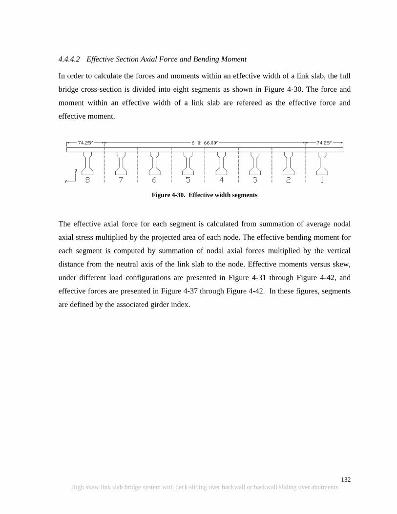
132
High skew link slab bridge system with deck sliding over backwall or backwall sliding over abutments
4.4.4.2 Effective Section Axial Force and Bending Moment
In order to calculate the forces and moments within an effective width of a link slab, the full
bridge cross-section is divided into eight segments as shown in Figure 4-30. The force and
moment within an effective width of a link slab are refereed as the effective force and
effective moment.
Figure 4-30. Effective width segments
The effective axial force for each segment is calculated from summation of average nodal
axial stress multiplied by the projected area of each node. The effective bending moment for
each segment is computed by summation of nodal axial forces multiplied by the vertical
distance from the neutral axis of the link slab to the node. Effective moments versus skew,
under different load configurations are presented in Figure 4-31 through Figure 4-42, and
effective forces are presented in Figure 4-37 through Figure 4-42. In these figures, segments
are defined by the associated girder index.
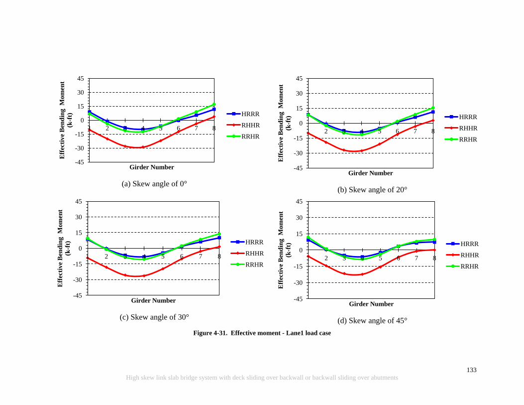
133
High skew link slab bridge system with deck sliding over backwall or backwall sliding over abutments
(a) Skew angle of 0°
(b) Skew angle of 20°
(c) Skew angle of 30°
(d) Skew angle of 45°
Figure 4-31. Effective moment - Lane1 load case
-45
-30
-15
0
15
30
45
1 2 3 4 5 6 7 8
Eff
ecti
ve
Ben
din
g M
om
ent
(k-f
t)
Girder Number
HRRR
RHHR
RRHR
-45
-30
-15
0
15
30
45
1 2 3 4 5 6 7 8
Eff
ecti
ve
Ben
din
g M
om
ent
(k-f
t)
Girder Number
HRRR
RHHR
RRHR
-45
-30
-15
0
15
30
45
1 2 3 4 5 6 7 8
Eff
ecti
ve
Ben
din
g M
om
ent
(k-f
t)
Girder Number
HRRR
RHHR
RRHR
-45
-30
-15
0
15
30
45
1 2 3 4 5 6 7 8
Eff
ecti
ve
Ben
din
g M
om
ent
(k-f
t)
Girder Number
HRRR
RHHR
RRHR
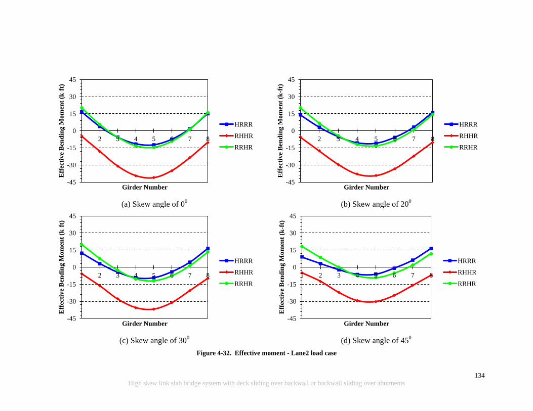
134
High skew link slab bridge system with deck sliding over backwall or backwall sliding over abutments
(a) Skew angle of 0
0
(b) Skew angle of 20
0
(c) Skew angle of 30
0
(d) Skew angle of 45
0
Figure 4-32. Effective moment - Lane2 load case
-45
-30
-15
0
15
30
45
1 2 3 4 5 6 7 8
Eff
ecti
ve
Ben
din
g M
om
ent
(k-f
t)
Girder Number
HRRR
RHHR
RRHR
-45
-30
-15
0
15
30
45
1 2 3 4 5 6 7 8
Eff
ecti
ve
Ben
din
g M
om
ent
(k-f
t)
Girder Number
HRRR
RHHR
RRHR
-45
-30
-15
0
15
30
45
1 2 3 4 5 6 7 8
Eff
ecti
ve
Ben
din
g M
om
ent
(k-f
t)
Girder Number
HRRR
RHHR
RRHR
-45
-30
-15
0
15
30
45
1 2 3 4 5 6 7 8 E
ffec
tiv
e B
end
ing
Mo
men
t (k
-ft)
Girder Number
HRRR
RHHR
RRHR
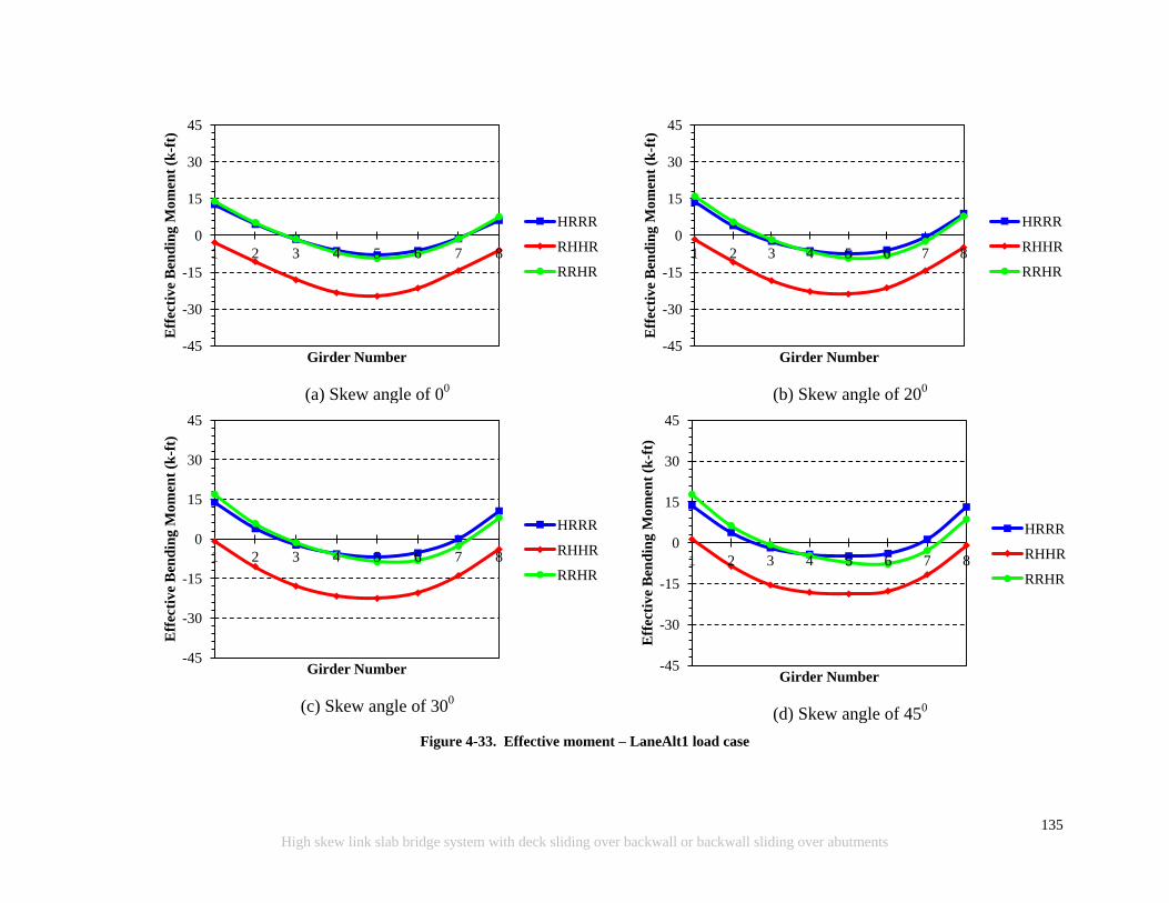
135
High skew link slab bridge system with deck sliding over backwall or backwall sliding over abutments
Figure 4-33. Effective moment – LaneAlt1 load case
(a) Skew angle of 0
0
(b) Skew angle of 20
0
(c) Skew angle of 30
0
(d) Skew angle of 45
0
-45
-30
-15
0
15
30
45
1 2 3 4 5 6 7 8
Eff
ecti
ve
Ben
din
g M
om
ent
(k-f
t)
Girder Number
HRRR
RHHR
RRHR
-45
-30
-15
0
15
30
45
1 2 3 4 5 6 7 8
Eff
ecti
ve
Ben
din
g M
om
ent
(k-f
t)
Girder Number
HRRR
RHHR
RRHR
-45
-30
-15
0
15
30
45
1 2 3 4 5 6 7 8
Eff
ecti
ve
Ben
din
g M
om
ent
(k-f
t)
Girder Number
HRRR
RHHR
RRHR
-45
-30
-15
0
15
30
45
1 2 3 4 5 6 7 8
Eff
ecti
ve
Ben
din
g M
om
ent
(k-f
t)
Girder Number
HRRR
RHHR
RRHR
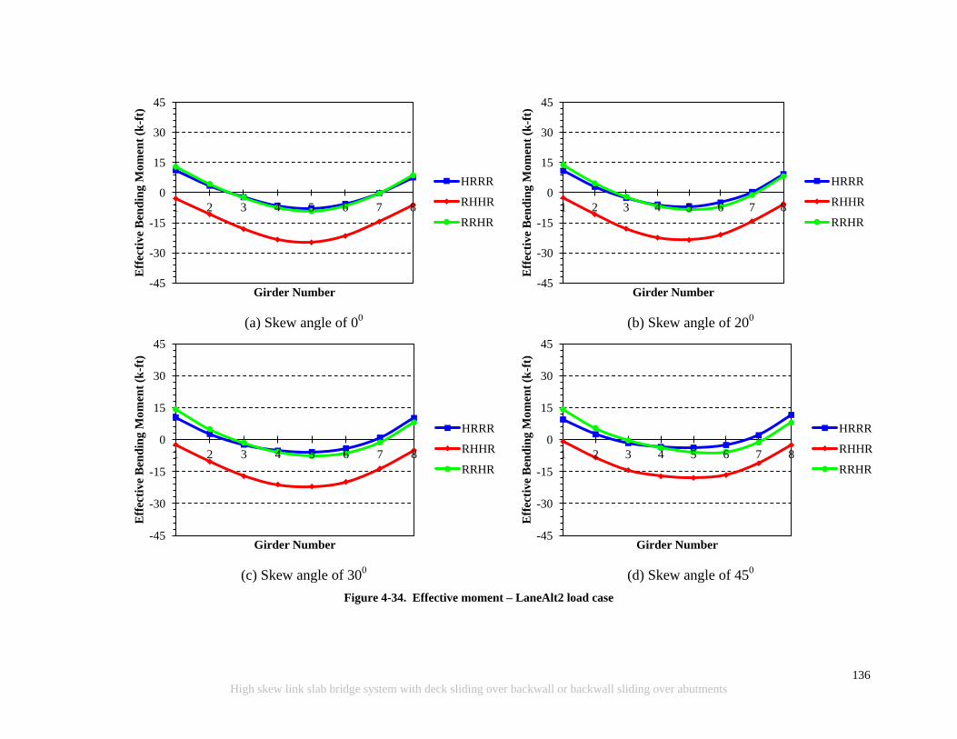
136
High skew link slab bridge system with deck sliding over backwall or backwall sliding over abutments
Figure 4-34. Effective moment – LaneAlt2 load case
(a) Skew angle of 0
0
(b) Skew angle of 20
0
(c) Skew angle of 30
0
(d) Skew angle of 45
0
-45
-30
-15
0
15
30
45
1 2 3 4 5 6 7 8
Eff
ecti
ve
Ben
din
g M
om
ent
(k-f
t)
Girder Number
HRRR
RHHR
RRHR
-45
-30
-15
0
15
30
45
1 2 3 4 5 6 7 8
Eff
ecti
ve
Ben
din
g M
om
ent
(k-f
t)
Girder Number
HRRR
RHHR
RRHR
-45
-30
-15
0
15
30
45
1 2 3 4 5 6 7 8
Eff
ecti
ve
Ben
din
g M
om
ent
(k-f
t)
Girder Number
HRRR
RHHR
RRHR
-45
-30
-15
0
15
30
45
1 2 3 4 5 6 7 8
Eff
ecti
ve
Ben
din
g M
om
ent
(k-f
t)
Girder Number
HRRR
RHHR
RRHR

137
High skew link slab bridge system with deck sliding over backwall or backwall sliding over abutments
(a) Skew angle of 0
0
(b) Skew angle of 20
0
(c) Skew angle of 30
0
(d) Skew angle of 45
0
Figure 4-35. Effective moment - NTG load case
-45
-30
-15
0
15
30
45
1 2 3 4 5 6 7 8
Eff
ecti
ve
Ben
din
g M
om
ent
(k-f
t)
Girder Number
HRRR
RHHR
RRHR
-45
-30
-15
0
15
30
45
1 2 3 4 5 6 7 8
Eff
ecti
ve
Ben
din
g M
om
ent
(k-f
t)
Girder Number
HRRR
RHHR
RRHR
-45
-30
-15
0
15
30
45
1 2 3 4 5 6 7 8
Eff
ecti
ve
Ben
din
g M
om
ent
(k-f
t)
Girder Number
HRRR
RHHR
RRHR
-45
-30
-15
0
15
30
45
1 2 3 4 5 6 7 8 E
ffec
tiv
e B
end
ing
M
om
ent
(k-f
t)
Girder Number
HRRR
RHHR
RRHR
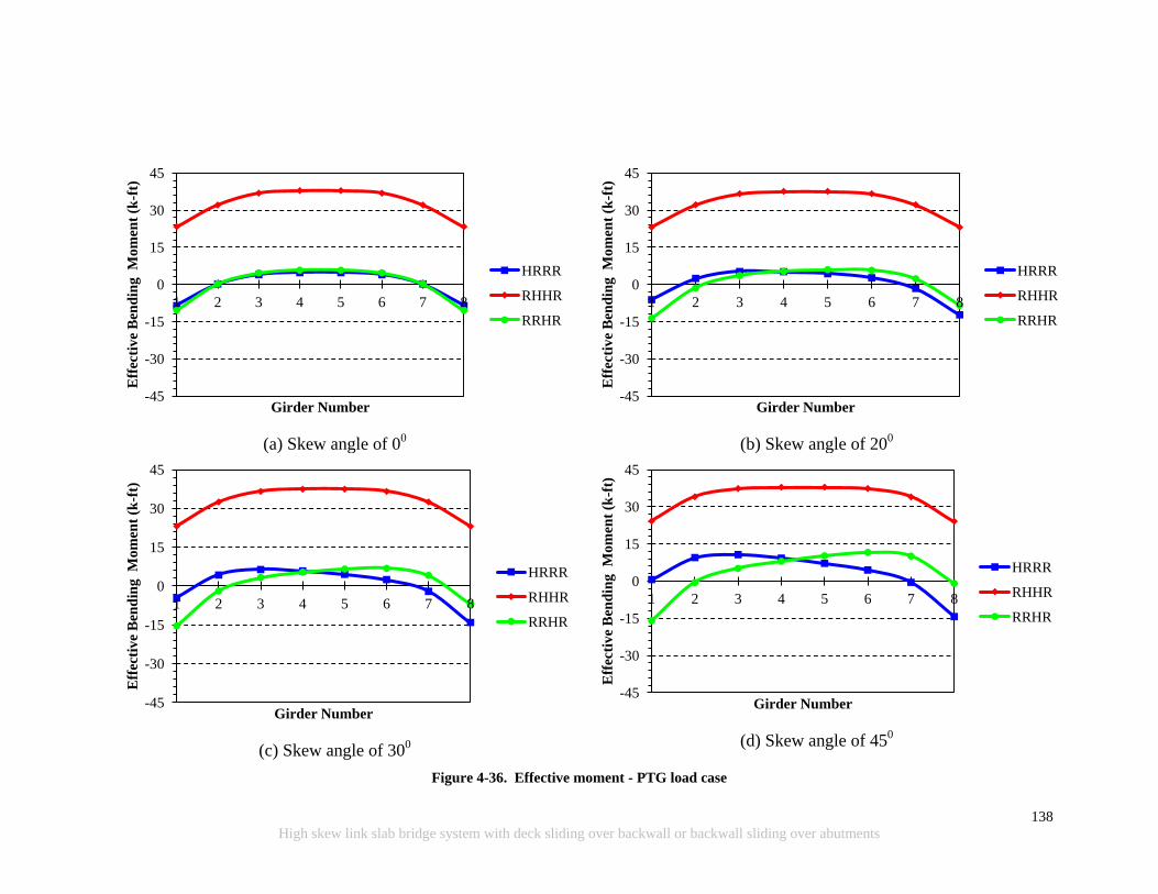
138
High skew link slab bridge system with deck sliding over backwall or backwall sliding over abutments
(a) Skew angle of 0
0
(b) Skew angle of 20
0
(c) Skew angle of 30
0
(d) Skew angle of 45
0
Figure 4-36. Effective moment - PTG load case
-45
-30
-15
0
15
30
45
1 2 3 4 5 6 7 8
Eff
ecti
ve
Ben
din
g M
om
ent
(k-f
t)
Girder Number
HRRR
RHHR
RRHR
-45
-30
-15
0
15
30
45
1 2 3 4 5 6 7 8
Eff
ecti
ve
Ben
din
g M
om
ent
(k-f
t)
Girder Number
HRRR
RHHR
RRHR
-45
-30
-15
0
15
30
45
1 2 3 4 5 6 7 8
Eff
ecti
ve
Ben
din
g M
om
ent
(k-f
t)
Girder Number
HRRR
RHHR
RRHR
-45
-30
-15
0
15
30
45
1 2 3 4 5 6 7 8 E
ffec
tiv
e B
end
ing
M
om
ent
(k-f
t)
Girder Number
HRRR
RHHR
RRHR
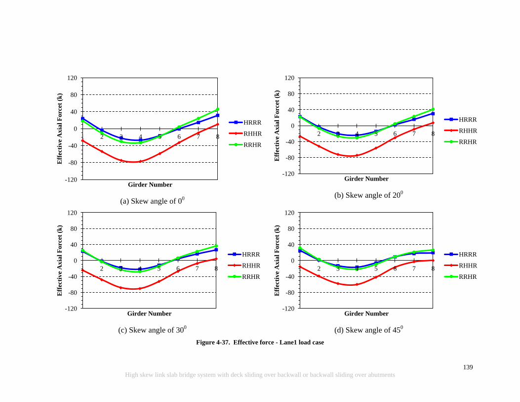
139
High skew link slab bridge system with deck sliding over backwall or backwall sliding over abutments
(a) Skew angle of 0
0
(b) Skew angle of 20
0
(c) Skew angle of 30
0
(d) Skew angle of 45
0
Figure 4-37. Effective force - Lane1 load case
-120
-80
-40
0
40
80
120
1 2 3 4 5 6 7 8
Eff
ecti
ve
Ax
ial
Fo
rcet
(k
)
Girder Number
HRRR
RHHR
RRHR
-120
-80
-40
0
40
80
120
1 2 3 4 5 6 7 8
Eff
ecti
ve
Ax
ial
Fo
rcet
(k
)
Girder Number
HRRR
RHHR
RRHR
-120
-80
-40
0
40
80
120
1 2 3 4 5 6 7 8
Eff
ecti
ve
Ax
ial
Forc
et (
k)
Girder Number
HRRR
RHHR
RRHR
-120
-80
-40
0
40
80
120
1 2 3 4 5 6 7 8
Eff
ecti
ve
Ax
ial
Forc
et (
k)
Girder Number
HRRR
RHHR
RRHR
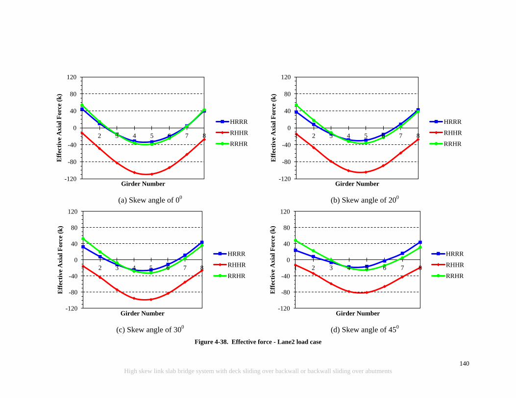
140
High skew link slab bridge system with deck sliding over backwall or backwall sliding over abutments
(a) Skew angle of 0
0
(b) Skew angle of 20
0
(c) Skew angle of 30
0
(d) Skew angle of 45
0
Figure 4-38. Effective force - Lane2 load case
-120
-80
-40
0
40
80
120
1 2 3 4 5 6 7 8
Eff
ecti
ve
Ax
ial
Fo
rce
(k)
Girder Number
HRRR
RHHR
RRHR
-120
-80
-40
0
40
80
120
1 2 3 4 5 6 7 8
Eff
ecti
ve
Ax
ial
Fo
rce
(k)
Girder Number
HRRR
RHHR
RRHR
-120
-80
-40
0
40
80
120
1 2 3 4 5 6 7 8
Eff
ecti
ve
Ax
ial
Forc
e (k
)
Girder Number
HRRR
RHHR
RRHR
-120
-80
-40
0
40
80
120
1 2 3 4 5 6 7 8 E
ffec
tiv
e A
xia
l F
orc
e (k
)
Girder Number
HRRR
RHHR
RRHR
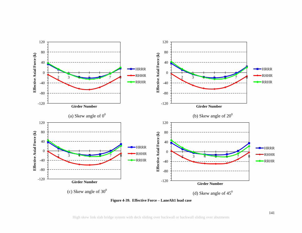
141
High skew link slab bridge system with deck sliding over backwall or backwall sliding over abutments
Figure 4-39. Effective Force – LaneAlt1 load case
(a) Skew angle of 0
0
(b) Skew angle of 20
0
(c) Skew angle of 30
0
(d) Skew angle of 45
0
-120
-80
-40
0
40
80
120
1 2 3 4 5 6 7 8
Eff
ecti
ve
Ax
ial
Fo
rce
(k)
Girder Number
HRRR
RHHR
RRHR
-120
-80
-40
0
40
80
120
1 2 3 4 5 6 7 8
Eff
ecti
ve
Ax
ial
Fo
rce
(k)
Girder Number
HRRR
RHHR
RRHR
-120
-80
-40
0
40
80
120
1 2 3 4 5 6 7 8
Eff
ecti
ve
Ax
ial
Forc
e (k
)
Girder Number
HRRR
RHHR
RRHR
-120
-80
-40
0
40
80
120
1 2 3 4 5 6 7 8 E
ffec
tiv
e A
xia
l F
orc
e (k
)
Girder Number
HRRR
RHHR
RRHR
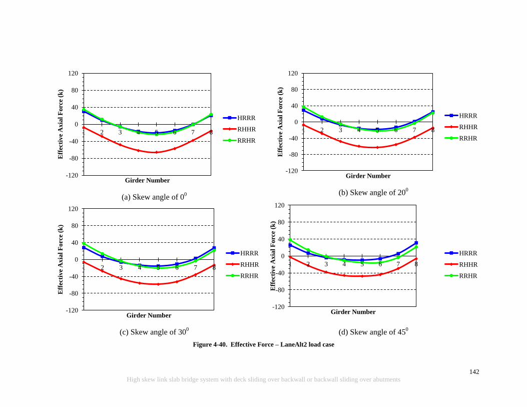
142
High skew link slab bridge system with deck sliding over backwall or backwall sliding over abutments
Figure 4-40. Effective Force – LaneAlt2 load case
(a) Skew angle of 0
0
(b) Skew angle of 20
0
(c) Skew angle of 30
0
(d) Skew angle of 45
0
-120
-80
-40
0
40
80
120
1 2 3 4 5 6 7 8
Eff
ecti
ve
Ax
ial
Fo
rce
(k)
Girder Number
HRRR
RHHR
RRHR
-120
-80
-40
0
40
80
120
1 2 3 4 5 6 7 8
Eff
ecti
ve
Ax
ial
Fo
rce
(k)
Girder Number
HRRR
RHHR
RRHR
-120
-80
-40
0
40
80
120
1 2 3 4 5 6 7 8
Eff
ecti
ve
Ax
ial
Forc
e (k
)
Girder Number
HRRR
RHHR
RRHR
-120
-80
-40
0
40
80
120
1 2 3 4 5 6 7 8
Eff
ecti
ve
Ax
ial
Forc
e (k
)
Girder Number
HRRR
RHHR
RRHR
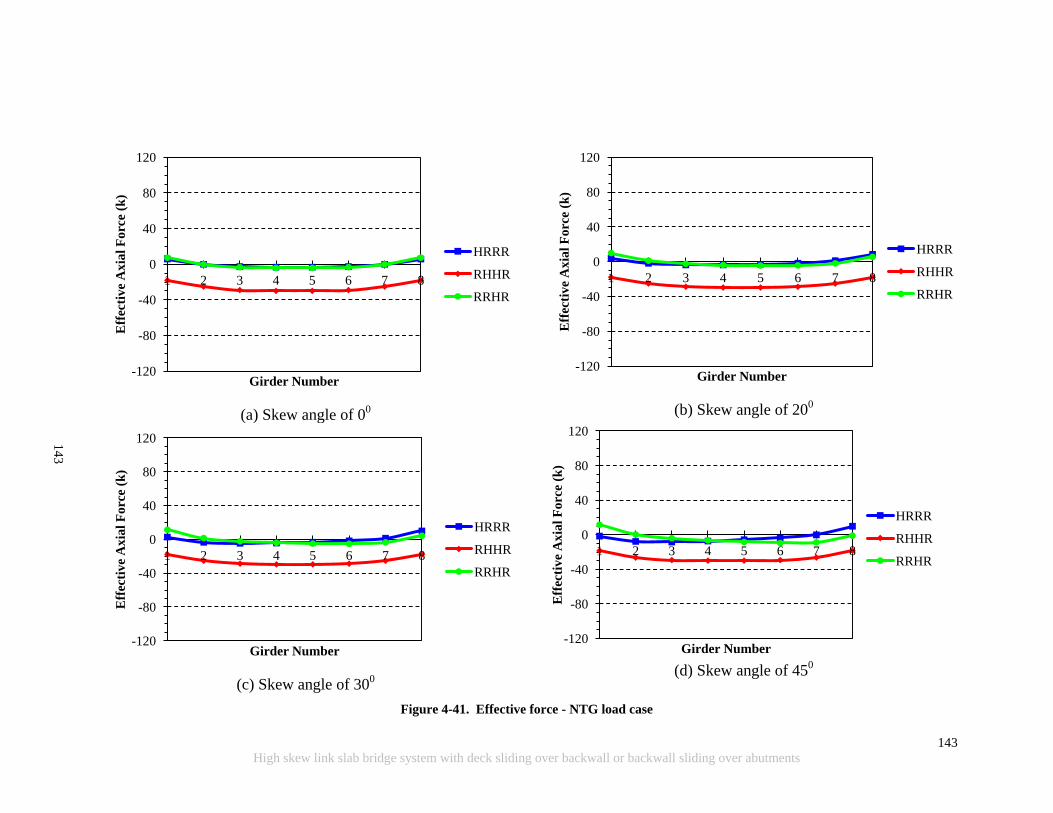
143
High skew link slab bridge system with deck sliding over backwall or backwall sliding over abutments
(a) Skew angle of 0
0
(b) Skew angle of 20
0
(c) Skew angle of 30
0
(d) Skew angle of 45
0
Figure 4-41. Effective force - NTG load case
-120
-80
-40
0
40
80
120
1 2 3 4 5 6 7 8
Eff
ecti
ve
Ax
ial
Fo
rce
(k)
Girder Number
HRRR
RHHR
RRHR
-120
-80
-40
0
40
80
120
1 2 3 4 5 6 7 8
Eff
ecti
ve
Ax
ial
Fo
rce
(k)
Girder Number
HRRR
RHHR
RRHR
-120
-80
-40
0
40
80
120
1 2 3 4 5 6 7 8
Eff
ecti
ve
Ax
ial
Forc
e (k
)
Girder Number
HRRR
RHHR
RRHR
-120
-80
-40
0
40
80
120
1 2 3 4 5 6 7 8 E
ffec
tiv
e A
xia
l F
orc
e (k
)
Girder Number
HRRR
RHHR
RRHR
14
3

144
High skew link slab bridge system with deck sliding over backwall or backwall sliding over abutments
(a) Skew angle of 0
0
(b) Skew angle of 20
0
(c) Skew angle of 30
0
(d) Skew angle of 45
0
Figure 4-42. Effective force - PTG load case
-120
-80
-40
0
40
80
120
1 2 3 4 5 6 7 8
Eff
ecti
ve
Ax
ial
Fo
rce
(k)
Girder Number
HRRR
RHHR
RRHR
-120
-80
-40
0
40
80
120
1 2 3 4 5 6 7 8
Eff
ecti
ve
Ax
ial
Fo
rce
(k)
Girder Number
HRRR
RHHR
RRHR
-120
-80
-40
0
40
80
120
1 2 3 4 5 6 7 8
Eff
ecti
ve
Ax
ial
Forc
e (k
)
Girder Number
HRRR
RHHR
RRHR
-120
-80
-40
0
40
80
120
1 2 3 4 5 6 7 8 E
ffec
tiv
e A
xia
l F
orc
e (k
)
Girder Number
HRRR
RHHR
RRHR
14
4
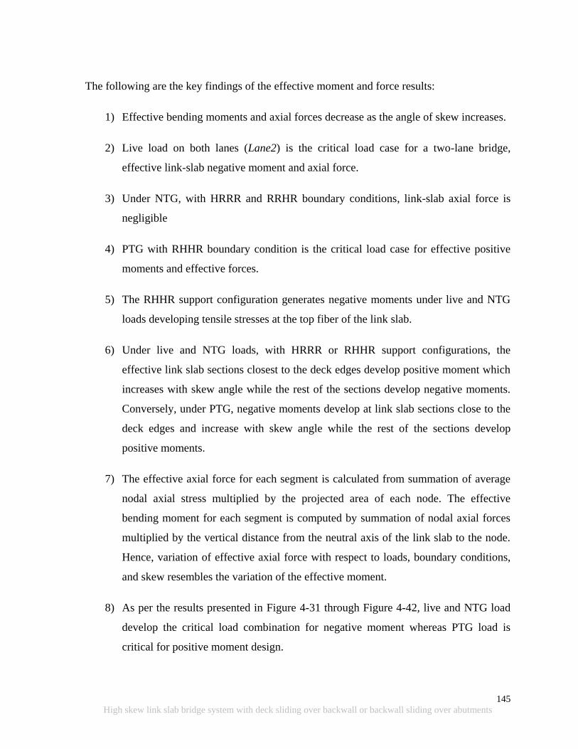
145
High skew link slab bridge system with deck sliding over backwall or backwall sliding over abutments
The following are the key findings of the effective moment and force results:
1) Effective bending moments and axial forces decrease as the angle of skew increases.
2) Live load on both lanes (Lane2) is the critical load case for a two-lane bridge,
effective link-slab negative moment and axial force.
3) Under NTG, with HRRR and RRHR boundary conditions, link-slab axial force is
negligible
4) PTG with RHHR boundary condition is the critical load case for effective positive
moments and effective forces.
5) The RHHR support configuration generates negative moments under live and NTG
loads developing tensile stresses at the top fiber of the link slab.
6) Under live and NTG loads, with HRRR or RHHR support configurations, the
effective link slab sections closest to the deck edges develop positive moment which
increases with skew angle while the rest of the sections develop negative moments.
Conversely, under PTG, negative moments develop at link slab sections close to the
deck edges and increase with skew angle while the rest of the sections develop
positive moments.
7) The effective axial force for each segment is calculated from summation of average
nodal axial stress multiplied by the projected area of each node. The effective
bending moment for each segment is computed by summation of nodal axial forces
multiplied by the vertical distance from the neutral axis of the link slab to the node.
Hence, variation of effective axial force with respect to loads, boundary conditions,
and skew resembles the variation of the effective moment.
8) As per the results presented in Figure 4-31 through Figure 4-42, live and NTG load
develop the critical load combination for negative moment whereas PTG load is
critical for positive moment design.

146
High skew link slab bridge system with deck sliding over backwall or backwall sliding over abutments
9) Effective moments and axial forces calculated from 3D analyses show that moment-
axial force interaction should be included in the link slab design for RHHR support
configuration.
10) In addition to axial force and moment effects, the design of high skew link slabs may
need to consider additional effects of link slab torsion and in-plane twist.
4.4.4.3 Link Slab Edge Stresses under In-plane Twist
HRRR and RRHR support conditions under PTG load develop the critical in-plane twist
(Mzz) in the link slab with increasing skew. The link slab develops axial loads under Mzz
linearly increasing towards the outside edges of the slab. Links slab edge stresses due to twist
are calculated along the right and left edges (note: right and left edges are defined based on
the vehicle traveling direction, i.e., from span A to span B, shown in Figure 4-6). Live loads
and NTG develop the largest tensile stresses at the edge top fiber while PTG develops the
largest stresses at the link slab bottom fiber. Top fiber stresses are calculated for live loads
and NTG loads are shown in Figure 4-43 and Figure 4-44. Bottom fiber stresses are
calculated for PTG and shown in Figure 4-45.
The debonded length of the link slab is measured from span A to span B as defined in Figure
4-6. In skew bridges, the maximum longitudinal stresses are developed near link slab ends
(i.e., at the point of debonding). The stresses developed under PTG are greater than the
stresses developed under live loads and NTG. In this particular bridge with HRRR support
conditions, stress developed under PTG is about 600 psi and exceeds tensile strength of grade
D concrete used in bridge decks (i.e., 0.24fc’). Deck concrete compressive strength is 4500
psi.
In order to accommodate high stresses developed along the link slab edges along the
debonded zone, a joint near the link slab end is provided allowing rebars to resist the entire
load. The joint needs to be saw cut and sealed for durability. Link slab reinforcement
designed for moment should be checked for twist developed at the edge segments. Additional
longitudinal reinforcement should be provided along the link slab edges if found inadequate.
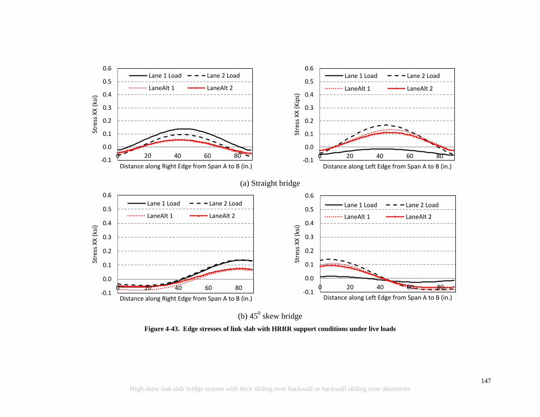
147
High skew link slab bridge system with deck sliding over backwall or backwall sliding over abutments
(a) Straight bridge
(b) 45
0 skew bridge
Figure 4-43. Edge stresses of link slab with HRRR support conditions under live loads
-0.1
0.0
0.1
0.2
0.3
0.4
0.5
0.6
0 20 40 60 80
Stre
ss X
X (
ksi)
Distance along Right Edge from Span A to B (in.)
Lane 1 Load Lane 2 Load
LaneAlt 1 LaneAlt 2
-0.1
0.0
0.1
0.2
0.3
0.4
0.5
0.6
0 20 40 60 80
Stre
ss X
X (
Kip
s)
Distance along Left Edge from Span A to B (in.)
Lane 1 Load Lane 2 Load
LaneAlt 1 LaneAlt 2
-0.1
0.0
0.1
0.2
0.3
0.4
0.5
0.6
0 20 40 60 80
Stre
ss X
X (
ksi)
Distance along Right Edge from Span A to B (in.)
Lane 1 Load Lane 2 Load
LaneAlt 1 LaneAlt 2
-0.1
0.0
0.1
0.2
0.3
0.4
0.5
0.6
0 20 40 60 80
Stre
ss X
X (
ksi)
Distance along Left Edge from Span A to B (in.)
Lane 1 Load Lane 2 Load
LaneAlt 1 LaneAlt 2
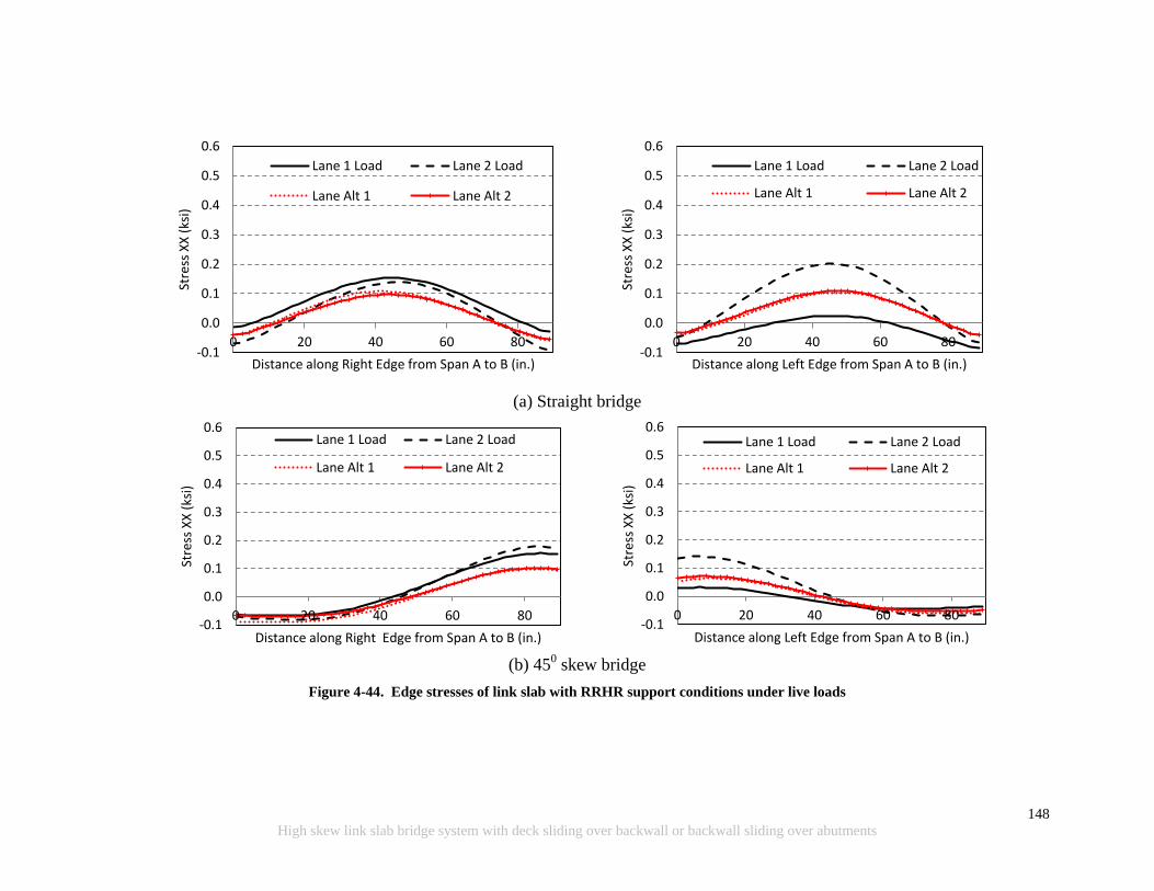
148
High skew link slab bridge system with deck sliding over backwall or backwall sliding over abutments
(a) Straight bridge
(b) 45
0 skew bridge
Figure 4-44. Edge stresses of link slab with RRHR support conditions under live loads
-0.1
0.0
0.1
0.2
0.3
0.4
0.5
0.6
0 20 40 60 80
Stre
ss X
X (
ksi)
Distance along Right Edge from Span A to B (in.)
Lane 1 Load Lane 2 Load
Lane Alt 1 Lane Alt 2
-0.1
0.0
0.1
0.2
0.3
0.4
0.5
0.6
0 20 40 60 80
Stre
ss X
X (
ksi)
Distance along Left Edge from Span A to B (in.)
Lane 1 Load Lane 2 Load
Lane Alt 1 Lane Alt 2
-0.1
0.0
0.1
0.2
0.3
0.4
0.5
0.6
0 20 40 60 80
Stre
ss X
X (
ksi)
Distance along Right Edge from Span A to B (in.)
Lane 1 Load Lane 2 Load
Lane Alt 1 Lane Alt 2
-0.1
0.0
0.1
0.2
0.3
0.4
0.5
0.6
0 20 40 60 80 St
ress
XX
(ks
i)
Distance along Left Edge from Span A to B (in.)
Lane 1 Load Lane 2 Load
Lane Alt 1 Lane Alt 2
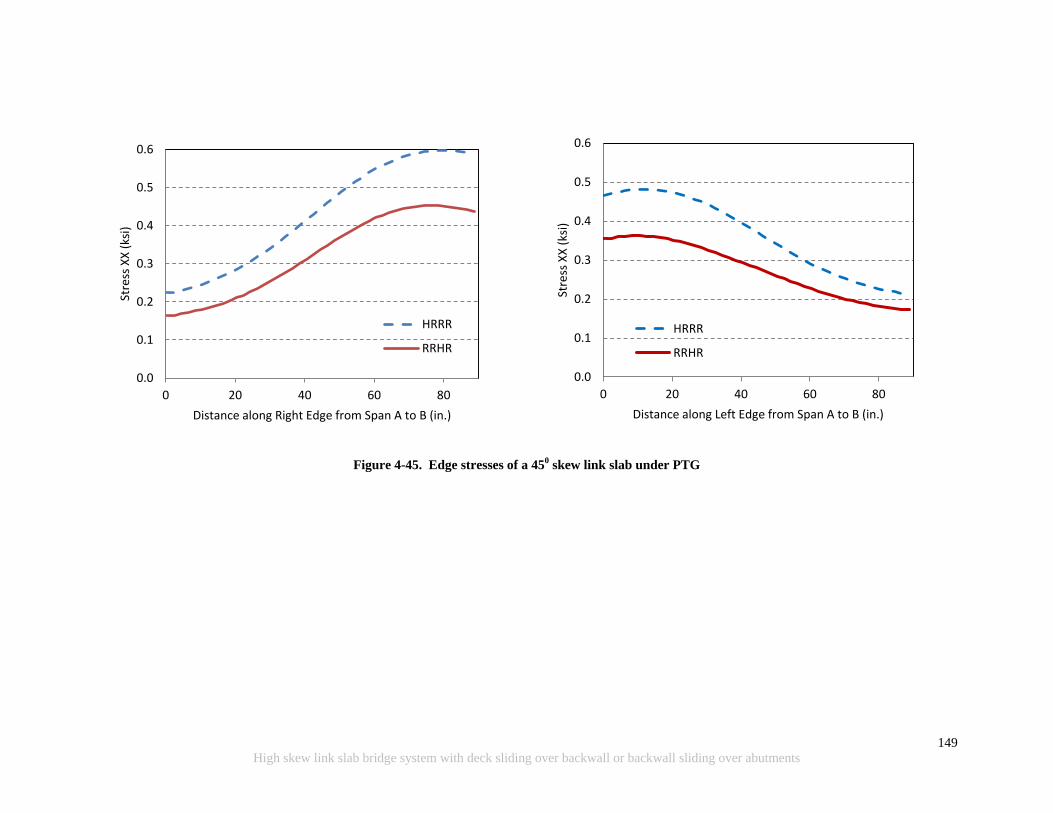
149
High skew link slab bridge system with deck sliding over backwall or backwall sliding over abutments
Figure 4-45. Edge stresses of a 450 skew link slab under PTG
0.0
0.1
0.2
0.3
0.4
0.5
0.6
0 20 40 60 80
Stre
ss X
X (
ksi)
Distance along Right Edge from Span A to B (in.)
HRRR
RRHR
0.0
0.1
0.2
0.3
0.4
0.5
0.6
0 20 40 60 80
Stre
ss X
X (
ksi)
Distance along Left Edge from Span A to B (in.)
HRRR
RRHR

150
High skew link slab bridge system with deck sliding over backwall or backwall sliding over abutments
4.4.4.4 Link-Slab Torsion with Skew
As skew increases, link slab torsion (Mxx) is developed under the LaneAlt1 load case (Figure
4-20). One way to deal with the torsion would be by providing cushioning between the girder
ends and the link slab. For this purpose, use of a soft material like neoprene or Styrofoam
over the girder ends underneath the link slab is investigated. The most critical case of a 450
skew link slab is analyzed under the LaneAlt1 load case, and the results are presented below.
As shown in Figure 4-46, longitudinal tensile stresses and contact stresses developed
underneath the link slab-girder contact points are reduced from the case without cushioning.
Further, resultant gross-section moments are reduced when cushioning materials are
introduced in between girder ends and the link slab (Figure 4-47).
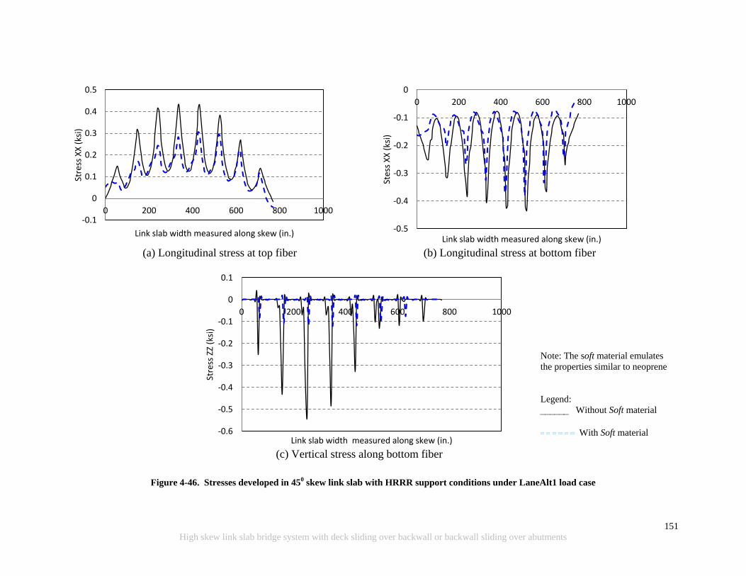
151
High skew link slab bridge system with deck sliding over backwall or backwall sliding over abutments
(a) Longitudinal stress at top fiber (b) Longitudinal stress at bottom fiber
(c) Vertical stress along bottom fiber
Figure 4-46. Stresses developed in 450 skew link slab with HRRR support conditions under LaneAlt1 load case
-0.1
0
0.1
0.2
0.3
0.4
0.5
0 200 400 600 800 1000
Stre
ss X
X (
ksi)
Link slab width measured along skew (in.) -0.5
-0.4
-0.3
-0.2
-0.1
0
0 200 400 600 800 1000
Stes
s X
X (
ksi)
Link slab width measured along skew (in.)
-0.6
-0.5
-0.4
-0.3
-0.2
-0.1
0
0.1
0 200 400 600 800 1000
Stre
ss Z
Z (k
si)
Link slab width measured along skew (in.)
Note: The soft material emulates
the properties similar to neoprene
Legend:
Without Soft material
With Soft material

152
High skew link slab bridge system with deck sliding over backwall or backwall sliding over abutments
(a) Link slab torsion (Mxx)
(b) Link slab bending moment (Myy)
(c) Link slab in-plane twist (Mzz)
Note: The soft material emulates the properties similar to neoprene.
Figure 4-47. Gross section moment with and without soft material – LaneAlt1 load case
-1600
-1200
-800
-400
0
400
800
1200
1600
0 15 30 45
Mo
emtn
(k
- f
t)
Skew (degrees)
HRRR HRRR - Soft
-1600
-1200
-800
-400
0
400
800
1200
1600
0 15 30 45
Mo
emtn
(k
- f
t)
Skew (degrees)
HRRR HRRR - Soft
-1600
-1200
-800
-400
0
400
800
1200
1600
0 15 30 45
Mo
men
t (k
- f
t)
Skew (degrees)
HRRR

153
High skew link slab bridge system with deck sliding over backwall or backwall sliding over abutments
Placing cushioning material between girder ends and the link slab reduces torsion and
resultant moments. However, there is no significant reduction in longitudinal stresses
developed along the link slab edge near the transition zone at the start of the debonded
region. There is a benefit in reducing contact stresses (stress zz in Figure 4-46) by using
cushioning material. Also, providing construction joints between the link slab and the deck
near the deck edges and additional reinforcement along the link slab‟s outside edges needs to
be incorporated for link slabs with HRRR and RRHR support configurations. Additional
reinforcement is not required for a link slab with RHHR support configuration because there
is no in-plane twist (Mzz) under PTG (Figure 4-36).
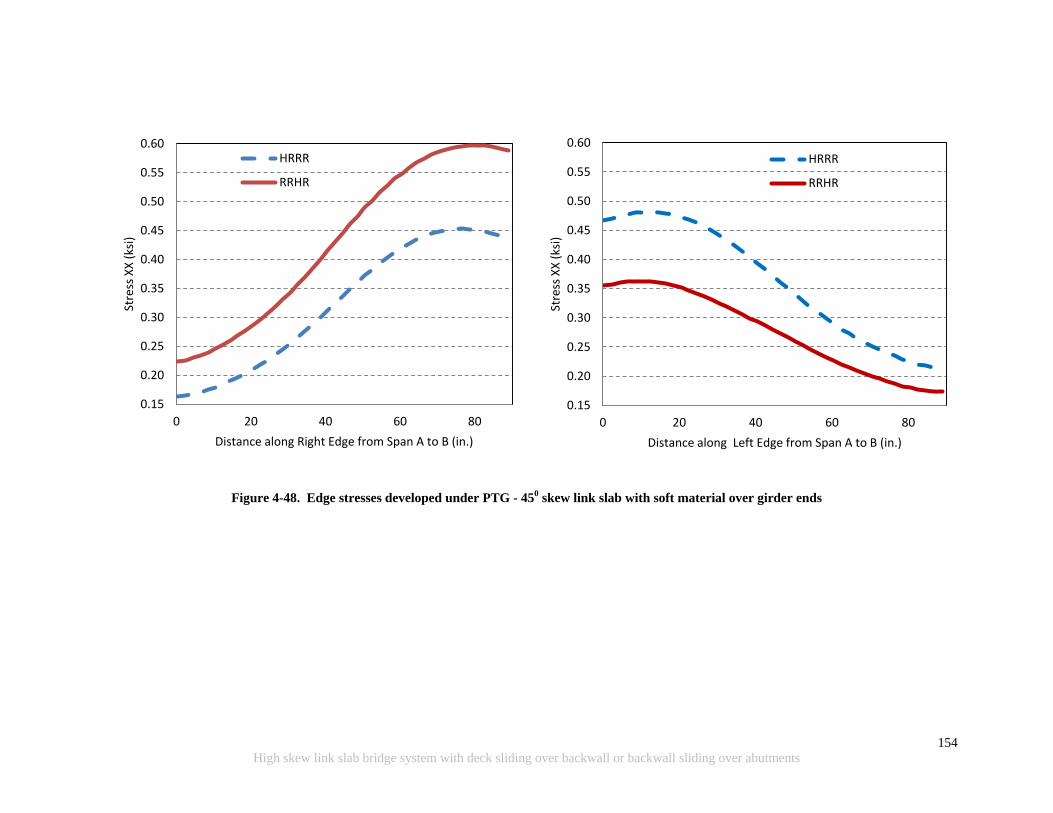
154
High skew link slab bridge system with deck sliding over backwall or backwall sliding over abutments
Figure 4-48. Edge stresses developed under PTG - 450 skew link slab with soft material over girder ends
0.15
0.20
0.25
0.30
0.35
0.40
0.45
0.50
0.55
0.60
0 20 40 60 80
Stre
ss X
X (
ksi)
Distance along Right Edge from Span A to B (in.)
HRRR
RRHR
0.15
0.20
0.25
0.30
0.35
0.40
0.45
0.50
0.55
0.60
0 20 40 60 80
Stre
ss X
X (
ksi)
Distance along Left Edge from Span A to B (in.)
HRRR
RRHR

155
High skew link slab bridge system with deck sliding over backwall or backwall sliding over abutments
4.4.4.5 Link Slab Stresses at the Transition Zone
Positive temperature gradient (PTG), with HRRR and RRHR support configurations,
generate large tensile stresses at the link slab bottom fibers near the end of the link slab
debonded region. Stress magnitude significantly increases directly over the girders (Figure
4-49). Longitudinal stress along the link slab bottom fiber at the end of the link slab
debonded region is shown in Figure 4-50 and Figure 4-51. As seen in the figures, the stresses
are greater than the tensile strength of concrete. Potential cracking can be dealt with by
introducing construction joints at the boundary of debonded and fully bonded regions. Also,
additional reinforcement may be required to resist the axial force.
Axial force developed within the tension region over the girders is calculated from the
stresses. Elements with tensile stresses are identified and shown in Figure 4-52. The
resultant tensile forces are the summation of incremental forces calculated by the stress
multiplied by the associated area. The maximum tensile forces calculated for HRRR and
RRHR support configurations are 33.3 kips/ft and 36.3 kips/ft. Adequacy of provided
reinforcement to resist such forces should be checked. See the link slab design example
provided in Appendix C for the methodology of checking the adequacy of link slab
reinforcement to resist the axial load developed in the link slab.
Figure 4-49. Link slab bottom fiber stresses under PTG load

156
High skew link slab bridge system with deck sliding over backwall or backwall sliding over abutments
Figure 4-50. Longitudinal stress distribution across north end of the 450 skew link slab bottom fiber
under PTG with HRRR support configuration
Figure 4-51. Longitudinal stress distribution across south end of the 450 skew link slab bottom fiber
under PTG with RRHR support configuration
0.0
0.2
0.4
0.6
0.8
1.0
1.2
1.4
1.6
1.8
0 200 400 600 800
Stre
ss X
X (
ksi)
Distance from Lane 1 to Lane 2 (in.)
0.0
0.2
0.4
0.6
0.8
1.0
1.2
1.4
1.6
1.8
2.0
0 100 200 300 400 500 600 700 800
Stre
ss X
X (
ksi)
Distance from Lane 1 to Lane 2 (in.)
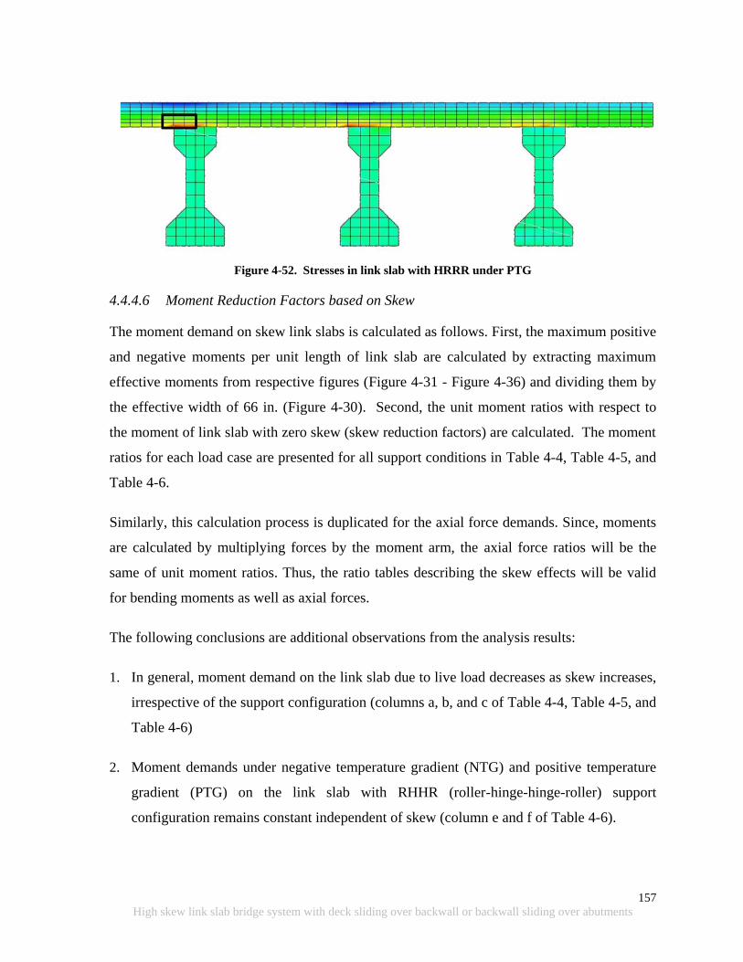
157
High skew link slab bridge system with deck sliding over backwall or backwall sliding over abutments
Figure 4-52. Stresses in link slab with HRRR under PTG
4.4.4.6 Moment Reduction Factors based on Skew
The moment demand on skew link slabs is calculated as follows. First, the maximum positive
and negative moments per unit length of link slab are calculated by extracting maximum
effective moments from respective figures (Figure 4-31 - Figure 4-36) and dividing them by
the effective width of 66 in. (Figure 4-30). Second, the unit moment ratios with respect to
the moment of link slab with zero skew (skew reduction factors) are calculated. The moment
ratios for each load case are presented for all support conditions in Table 4-4, Table 4-5, and
Table 4-6.
Similarly, this calculation process is duplicated for the axial force demands. Since, moments
are calculated by multiplying forces by the moment arm, the axial force ratios will be the
same of unit moment ratios. Thus, the ratio tables describing the skew effects will be valid
for bending moments as well as axial forces.
The following conclusions are additional observations from the analysis results:
1. In general, moment demand on the link slab due to live load decreases as skew increases,
irrespective of the support configuration (columns a, b, and c of Table 4-4, Table 4-5, and
Table 4-6)
2. Moment demands under negative temperature gradient (NTG) and positive temperature
gradient (PTG) on the link slab with RHHR (roller-hinge-hinge-roller) support
configuration remains constant independent of skew (column e and f of Table 4-6).

158
High skew link slab bridge system with deck sliding over backwall or backwall sliding over abutments
3. The maximum effective negative and positive moment envelope patterns across the link
slab under live (Lane 2) and NTG loads are similar (Figure 4-31 - Figure 4-36). Both load
effects should be combined.
4. The link slab maximum effective positive and negative moment locations under PTG are
different from NTG (Figure 4-31 - Figure 4-36). PTG should be considered independent
from live loads and NTG.
5. Lane 2 is the governing live load case for this specific bridge configuration, for all
support configurations (column b of Table 4-4, Table 4-5, and Table 4-6).
6. The link slab moment with HRRR and RRHR support configuration is much less than the
cracking moment capacity; additional reinforcement may be required to resist large
tensile stresses developed along link slab bottom fibers within the end of the link slab
debonded region (Figure 4-45 and Figure 4-48 - Figure 4-52).
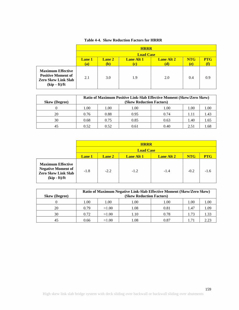
159
High skew link slab bridge system with deck sliding over backwall or backwall sliding over abutments
Table 4-4. Skew Reduction Factors for HRRR
HRRR
Load Case
Lane 1
(a)
Lane 2
(b)
Lane Alt 1
(c)
Lane Alt 2
(d)
NTG
(e)
PTG
(f)
Maximum Effective
Positive Moment of
Zero Skew Link Slab
(kip – ft)/ft
2.1 3.0 1.9 2.0 0.4 0.9
Skew (Degree)
Ratio of Maximum Positive Link-Slab Effective Moment (Skew/Zero Skew)
(Skew Reduction Factors)
0 1.00 1.00 1.00 1.00 1.00 1.00
20 0.76 0.88 0.95 0.74 1.11 1.43
30 0.68 0.75 0.85 0.63 1.40 1.65
45 0.52 0.52 0.61 0.40 2.51 1.68
HRRR
Load Case
Lane 1 Lane 2 Lane Alt 1 Lane Alt 2 NTG PTG
Maximum Effective
Negative Moment of
Zero Skew Link Slab
(kip - ft)/ft
-1.8 -2.2 -1.2 -1.4 -0.2 -1.6
Skew (Degree)
Ratio of Maximum Negative Link-Slab Effective Moment (Skew/Zero Skew)
(Skew Reduction Factors)
0 1.00 1.00 1.00 1.00 1.00 1.00
20 0.79 ≈1.00 1.08 0.81 1.47 1.09
30 0.72 ≈1.00 1.10 0.78 1.73 1.33
45 0.66 ≈1.00 1.08 0.87 1.71 2.23

160
High skew link slab bridge system with deck sliding over backwall or backwall sliding over abutments
Table 4-5. Skew Reduction Factors for RRHR
RRHR
Load Case
Lane 1
(a)
Lane 2
(b)
Lane Alt 1
(c)
Lane Alt 2
(d)
NTG
(e)
PTG
(f)
Maximum Effective
Positive Moment of
Zero Skew Link
Slab
(kip - ft)/ft
2.6 3.7 2.1 2.0 0.5 1.0
Skew (Degree)
Ratio of Maximum Positive Link-Slab Effective Moment (Skew/Zero Skew)
(Skew Reduction Factors)
0 1.00 1.00 1.00 1.00 1.00 1.00
20 0.92 0.92 0.99 0.93 1.05 1.32
30 0.84 0.83 0.92 0.83 1.25 1.49
45 0.68 0.63 0.83 0.64 2.29 1.54
RRHR
Load Case
Lane 1 Lane 2 Lane Alt 1 Lane Alt 2 NTG PTG
Maximum Effective
Negative Moment of
Zero Skew Link
Slab
(kip - ft)/ft
-1.9 -2.7 -1.4 -1.4 -0.3 -1.9
Skew (Degree)
Ratio of Maximum Negative Link-Slab Effective Moment (Skew/Zero Skew)
(Skew Reduction Factors)
0 1.00 1.00 1.00 1.00 1.00 1.00
20 0.90 1.00 1.15 1.08 1.36 1.04
30 0.80 0.98 1.21 1.10 1.56 1.18
45 0.69 0.90 1.28 1.10 1.59 2.01
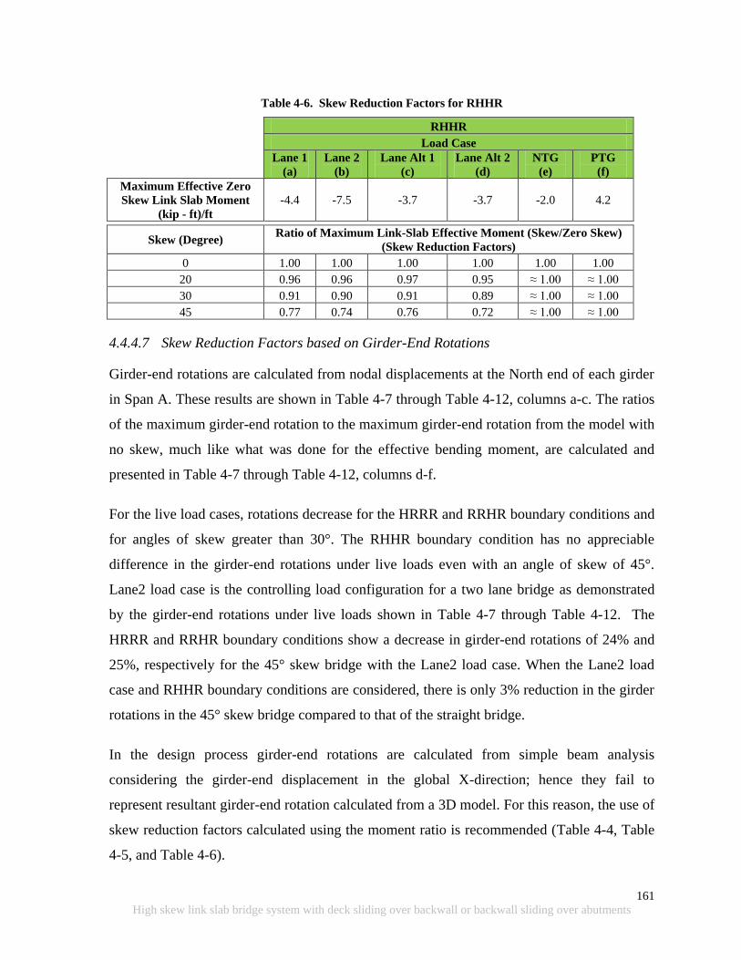
161
High skew link slab bridge system with deck sliding over backwall or backwall sliding over abutments
Table 4-6. Skew Reduction Factors for RHHR
RHHR
Load Case
Lane 1
(a)
Lane 2
(b)
Lane Alt 1
(c)
Lane Alt 2
(d)
NTG
(e)
PTG
(f)
Maximum Effective Zero
Skew Link Slab Moment
(kip - ft)/ft
-4.4 -7.5 -3.7 -3.7 -2.0 4.2
Skew (Degree)
Ratio of Maximum Link-Slab Effective Moment (Skew/Zero Skew)
(Skew Reduction Factors)
0 1.00 1.00 1.00 1.00 1.00 1.00
20 0.96 0.96 0.97 0.95 ≈ 1.00 ≈ 1.00
30 0.91 0.90 0.91 0.89 ≈ 1.00 ≈ 1.00
45 0.77 0.74 0.76 0.72 ≈ 1.00 ≈ 1.00
4.4.4.7 Skew Reduction Factors based on Girder-End Rotations
Girder-end rotations are calculated from nodal displacements at the North end of each girder
in Span A. These results are shown in Table 4-7 through Table 4-12, columns a-c. The ratios
of the maximum girder-end rotation to the maximum girder-end rotation from the model with
no skew, much like what was done for the effective bending moment, are calculated and
presented in Table 4-7 through Table 4-12, columns d-f.
For the live load cases, rotations decrease for the HRRR and RRHR boundary conditions and
for angles of skew greater than 30°. The RHHR boundary condition has no appreciable
difference in the girder-end rotations under live loads even with an angle of skew of 45°.
Lane2 load case is the controlling load configuration for a two lane bridge as demonstrated
by the girder-end rotations under live loads shown in Table 4-7 through Table 4-12. The
HRRR and RRHR boundary conditions show a decrease in girder-end rotations of 24% and
25%, respectively for the 45° skew bridge with the Lane2 load case. When the Lane2 load
case and RHHR boundary conditions are considered, there is only 3% reduction in the girder
rotations in the 45° skew bridge compared to that of the straight bridge.
In the design process girder-end rotations are calculated from simple beam analysis
considering the girder-end displacement in the global X-direction; hence they fail to
represent resultant girder-end rotation calculated from a 3D model. For this reason, the use of
skew reduction factors calculated using the moment ratio is recommended (Table 4-4, Table
4-5, and Table 4-6).
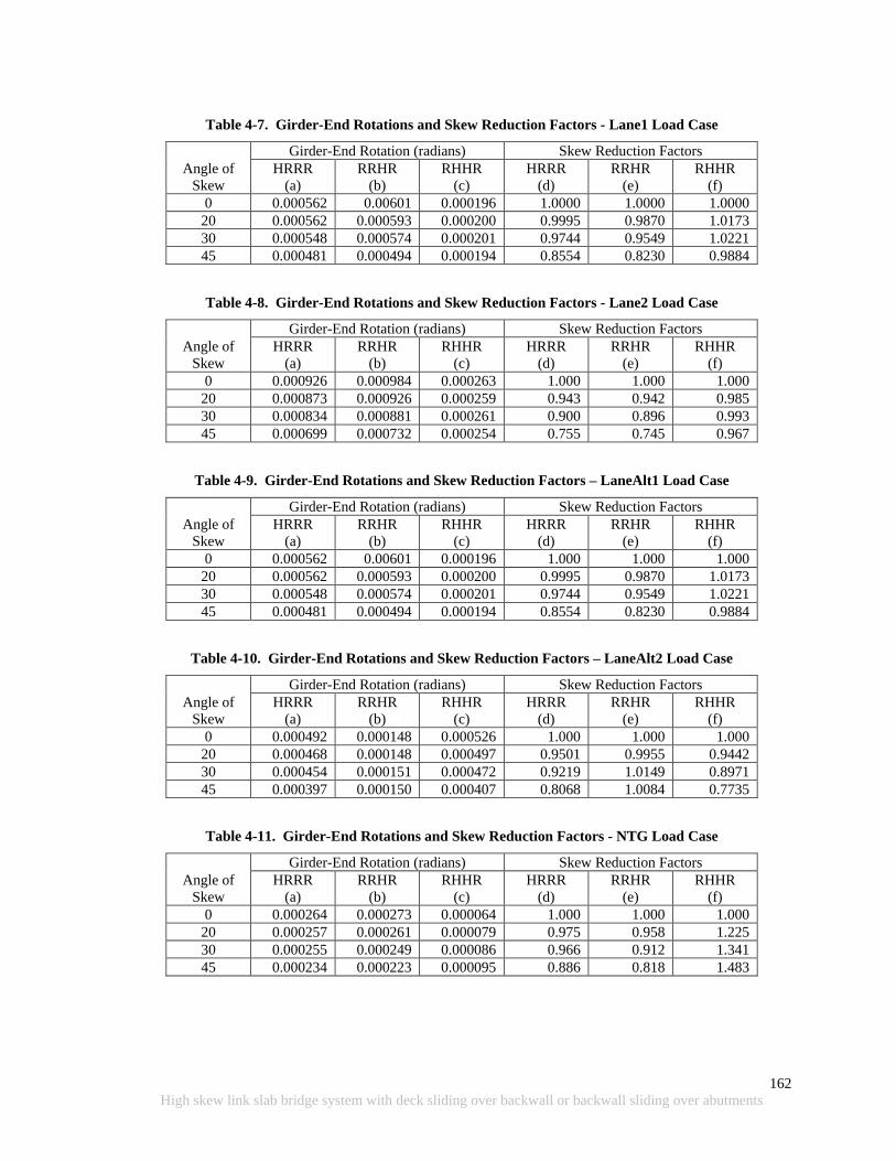
162
High skew link slab bridge system with deck sliding over backwall or backwall sliding over abutments
Table 4-7. Girder-End Rotations and Skew Reduction Factors - Lane1 Load Case
Angle of
Skew
Girder-End Rotation (radians) Skew Reduction Factors
HRRR
(a)
RRHR
(b)
RHHR
(c)
HRRR
(d)
RRHR
(e)
RHHR
(f)
0 0.000562 0.00601 0.000196 1.0000 1.0000 1.0000
20 0.000562 0.000593 0.000200 0.9995 0.9870 1.0173
30 0.000548 0.000574 0.000201 0.9744 0.9549 1.0221
45 0.000481 0.000494 0.000194 0.8554 0.8230 0.9884
Table 4-8. Girder-End Rotations and Skew Reduction Factors - Lane2 Load Case
Angle of
Skew
Girder-End Rotation (radians) Skew Reduction Factors
HRRR
(a)
RRHR
(b)
RHHR
(c)
HRRR
(d)
RRHR
(e)
RHHR
(f)
0 0.000926 0.000984 0.000263 1.000 1.000 1.000
20 0.000873 0.000926 0.000259 0.943 0.942 0.985
30 0.000834 0.000881 0.000261 0.900 0.896 0.993
45 0.000699 0.000732 0.000254 0.755 0.745 0.967
Table 4-9. Girder-End Rotations and Skew Reduction Factors – LaneAlt1 Load Case
Angle of
Skew
Girder-End Rotation (radians) Skew Reduction Factors
HRRR
(a)
RRHR
(b)
RHHR
(c)
HRRR
(d)
RRHR
(e)
RHHR
(f)
0 0.000562 0.00601 0.000196 1.000 1.000 1.000
20 0.000562 0.000593 0.000200 0.9995 0.9870 1.0173
30 0.000548 0.000574 0.000201 0.9744 0.9549 1.0221
45 0.000481 0.000494 0.000194 0.8554 0.8230 0.9884
Table 4-10. Girder-End Rotations and Skew Reduction Factors – LaneAlt2 Load Case
Angle of
Skew
Girder-End Rotation (radians) Skew Reduction Factors
HRRR
(a)
RRHR
(b)
RHHR
(c)
HRRR
(d)
RRHR
(e)
RHHR
(f)
0 0.000492 0.000148 0.000526 1.000 1.000 1.000
20 0.000468 0.000148 0.000497 0.9501 0.9955 0.9442
30 0.000454 0.000151 0.000472 0.9219 1.0149 0.8971
45 0.000397 0.000150 0.000407 0.8068 1.0084 0.7735
Table 4-11. Girder-End Rotations and Skew Reduction Factors - NTG Load Case
Angle of
Skew
Girder-End Rotation (radians) Skew Reduction Factors
HRRR
(a)
RRHR
(b)
RHHR
(c)
HRRR
(d)
RRHR
(e)
RHHR
(f)
0 0.000264 0.000273 0.000064 1.000 1.000 1.000
20 0.000257 0.000261 0.000079 0.975 0.958 1.225
30 0.000255 0.000249 0.000086 0.966 0.912 1.341
45 0.000234 0.000223 0.000095 0.886 0.818 1.483

163
High skew link slab bridge system with deck sliding over backwall or backwall sliding over abutments
Table 4-12. Girder-End Rotations and Skew Reduction Factors - PTG Load Case
Angle of
Skew
Girder-End Rotation (radians) Skew Reduction Factors
HRRR
(a)
RRHR
(b)
RHHR
(c)
HRRR
(d)
RRHR
(e)
RHHR
(f)
0 -0.000989 -0.001019 -0.000220 1.000 1.000 1.000
20 -0.000982 -0.000994 -0.000271 0.993 0.975 1.230
30 -0.000978 -0.000963 -0.000298 0.989 0.946 1.351
45 -0.000930 -0.000901 -0.000335 0.940 0.885 1.523
4.4.5 Skew Link Slab Design Procedure
4.4.5.1 Overview
The skew link slab design is based on the bending moment and axial force calculated from
analysis that incorporates the effects of skew under specific load combinations. The
simplified analysis procedure for bridges with no skew was presented in Ulku et al. (2009).
The analysis procedure assumes that the link slab does not provide any continuity between
spans. Therefore, the spans are analyzed as simply supported. The girder-end rotations are
calculated from the design load combinations. Imposing compatibility, the link slab is
subjected to a rotation equal to the girder-end rotation. The link slab moment is calculated
from Eq. 4-10 by substituting the beam end rotation.
(4-10)
where
M = Link slab bending moment (k-in)
Ec = Elastic modulus of concrete (ksi)
ILS = Moment of inertia of the link slab (in4)
LLS = Length of link slab (in)
= Girder-end rotation (radians)
The simplified link-slab design procedure by Caner and Zia (1998) was updated by Ulku et
al. (2009) to incorporate the effects of bearing configurations and thermal gradient loads, also
for bridges with zero skew. The procedure developed here is the modification of the
procedure by Ulku et al. (2009) to incorporate the effects of link-slab skew.

164
High skew link slab bridge system with deck sliding over backwall or backwall sliding over abutments
The load demand calculation based on the modified procedure and link slab design is
described below on a numerical example with the geometry of the specific bridge used in the
FE analysis. Geometric and material property data used in this section as well as in the
design example presented in Appendix C are given in Figure 4-53 and Table 4-13.
Figure 4-53. AASHTO Type III girder and composite section geometric properties
Table 4-13. Material and Geometric Properties used in Link Slab Design Example
Boundary condition RHHR
Skew () 45 deg.
Compressive strength of concrete (fc’) 4,500 psi
Unit weight of concrete (wc) 0.15 kcf
Concrete modulus of elasticity (Ec)
(AASHTO LRFD Section 5.4.2.4)
4,067 psi
Reinforcement yield strength (fy) 60 ksi
Steel modulus of elasticity (Es) 29,000 ksi
Link slab length (LLS) 84.4 in.
Effective deck width (B)+ 66 in.
Link slab thickness 9 in.
Moment of inertia of link slab (ILS) 4,009.5 in4
Deck overhang (on either side of the beam) 25 in.
Moment of inertia of the girder (Igirder) 125,390 in4
Moment of inertia of the composite section
(Icomposite)
375,678 in4
+ Link slab section perpendicular to bridge longitudinal axis is considered in the example because design
moments are calculated perpendicular to bridge longitudinal axis (Figure 4-31 - Figure 4-42).
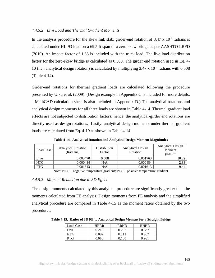
165
High skew link slab bridge system with deck sliding over backwall or backwall sliding over abutments
4.4.5.2 Live Load and Thermal Gradient Moments
In the analysis procedure for the skew link slab, girder-end rotation of 3.47 x 10⁻³
radians is
calculated under HL-93 load on a 69.5 ft span of a zero-skew bridge as per AASHTO LRFD
(2010). An impact factor of 1.33 is included with the truck load. The live load distribution
factor for the zero-skew bridge is calculated as 0.508. The girder end rotation used in Eq. 4-
10 (i.e., analytical design rotation) is calculated by multiplying 3.47 x 10⁻³
radians with 0.508
(Table 4-14).
Girder-end rotations for thermal gradient loads are calculated following the procedure
presented by Ulku et al. (2009). (Design example in Appendix C is included for more details;
a MathCAD calculation sheet is also included in Appendix D.) The analytical rotations and
analytical design moments for all three loads are shown in Table 4-14. Thermal gradient load
effects are not subjected to distribution factors; hence, the analytical-girder end rotations are
directly used as design rotations. Lastly, analytical design moments under thermal gradient
loads are calculated from Eq. 4-10 as shown in Table 4-14.
Table 4-14. Analytical Rotation and Analytical Design Moment Magnitudes
Load Case Analytical Rotation
(Radians)
Distribution
Factor
Analytical Design
Rotation
Analytical Design
Moment
(k-ft)/ft
Live 0.003470 0.508 0.001763 10.32
NTG 0.000484 N/A 0.000484 2.83
PTG 0.001613 N/A 0.001613 9.44
Note: NTG – negative temperature gradient; PTG – positive temperature gradient
4.4.5.3 Moment Reduction due to 3D Effect
The design moments calculated by this analytical procedure are significantly greater than the
moments calculated from FE analysis. Design moments from FE analysis and the simplified
analytical procedure are compared in Table 4-15 as the moment ratios obtained by the two
procedures.
Table 4-15. Ratios of 3D FE to Analytical Design Moment for a Straight Bridge
Load Case HRRR RRHR RHHR
Live 0.218 0.257 0.887
NTG 0.092 0.111 0.967
PTG 0.080 0.100 0.961
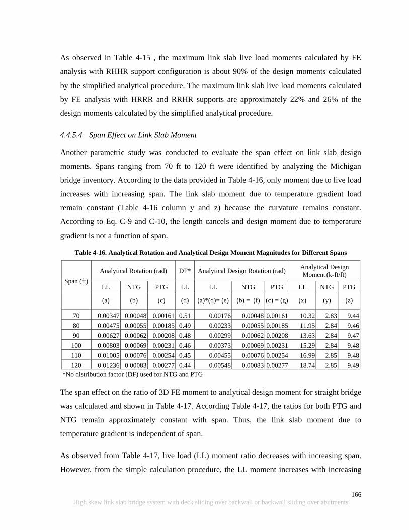
166
High skew link slab bridge system with deck sliding over backwall or backwall sliding over abutments
As observed in Table 4-15 , the maximum link slab live load moments calculated by FE
analysis with RHHR support configuration is about 90% of the design moments calculated
by the simplified analytical procedure. The maximum link slab live load moments calculated
by FE analysis with HRRR and RRHR supports are approximately 22% and 26% of the
design moments calculated by the simplified analytical procedure.
4.4.5.4 Span Effect on Link Slab Moment
Another parametric study was conducted to evaluate the span effect on link slab design
moments. Spans ranging from 70 ft to 120 ft were identified by analyzing the Michigan
bridge inventory. According to the data provided in Table 4-16, only moment due to live load
increases with increasing span. The link slab moment due to temperature gradient load
remain constant (Table 4-16 column y and z) because the curvature remains constant.
According to Eq. C-9 and C-10, the length cancels and design moment due to temperature
gradient is not a function of span.
Table 4-16. Analytical Rotation and Analytical Design Moment Magnitudes for Different Spans
Span (ft)
Analytical Rotation (rad) DF* Analytical Design Rotation (rad) Analytical Design
Moment (k-ft/ft)
LL NTG PTG LL LL NTG PTG LL NTG PTG
(a) (b) (c) (d) (a)*(d)= (e) (b) = (f) (c) = (g) (x) (y) (z)
70 0.00347 0.00048 0.00161 0.51 0.00176 0.00048 0.00161 10.32 2.83 9.44
80 0.00475 0.00055 0.00185 0.49 0.00233 0.00055 0.00185 11.95 2.84 9.46
90 0.00627 0.00062 0.00208 0.48 0.00299 0.00062 0.00208 13.63 2.84 9.47
100 0.00803 0.00069 0.00231 0.46 0.00373 0.00069 0.00231 15.29 2.84 9.48
110 0.01005 0.00076 0.00254 0.45 0.00455 0.00076 0.00254 16.99 2.85 9.48
120 0.01236 0.00083 0.00277 0.44 0.00548 0.00083 0.00277 18.74 2.85 9.49
*No distribution factor (DF) used for NTG and PTG
The span effect on the ratio of 3D FE moment to analytical design moment for straight bridge
was calculated and shown in Table 4-17. According Table 4-17, the ratios for both PTG and
NTG remain approximately constant with span. Thus, the link slab moment due to
temperature gradient is independent of span.
As observed from Table 4-17, live load (LL) moment ratio decreases with increasing span.
However, from the simple calculation procedure, the LL moment increases with increasing
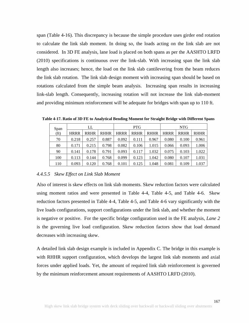
167
High skew link slab bridge system with deck sliding over backwall or backwall sliding over abutments
span (Table 4-16). This discrepancy is because the simple procedure uses girder end rotation
to calculate the link slab moment. In doing so, the loads acting on the link slab are not
considered. In 3D FE analysis, lane load is placed on both spans as per the AASHTO LRFD
(2010) specifications is continuous over the link-slab. With increasing span the link slab
length also increases; hence, the load on the link slab cantilevering from the beam reduces
the link slab rotation. The link slab design moment with increasing span should be based on
rotations calculated from the simple beam analysis. Increasing span results in increasing
link-slab length. Consequently, increasing rotation will not increase the link slab-moment
and providing minimum reinforcement will be adequate for bridges with span up to 110 ft.
Table 4-17. Ratio of 3D FE to Analytical Bending Moment for Straight Bridge with Different Spans
Span
(ft)
LL PTG NTG
HRRR RRHR RHHR HRRR RRHR RHHR HRRR RRHR RHHR
70 0.218 0.257 0.887 0.092 0.111 0.967 0.080 0.100 0.961
80 0.171 0.215 0.798 0.082 0.106 1.015 0.066 0.093 1.006
90 0.141 0.178 0.791 0.093 0.117 1.032 0.075 0.103 1.022
100 0.113 0.144 0.768 0.099 0.123 1.042 0.080 0.107 1.031
110 0.093 0.120 0.768 0.101 0.125 1.048 0.081 0.109 1.037
4.4.5.5 Skew Effect on Link Slab Moment
Also of interest is skew effects on link slab moments. Skew reduction factors were calculated
using moment ratios and were presented in Table 4-4, Table 4-5, and Table 4-6. Skew
reduction factors presented in Table 4-4, Table 4-5, and Table 4-6 vary significantly with the
live loads configurations, support configurations under the link slab, and whether the moment
is negative or positive. For the specific bridge configuration used in the FE analysis, Lane 2
is the governing live load configuration. Skew reduction factors show that load demand
decreases with increasing skew.
A detailed link slab design example is included in Appendix C. The bridge in this example is
with RHHR support configuration, which develops the largest link slab moments and axial
forces under applied loads. Yet, the amount of required link slab reinforcement is governed
by the minimum reinforcement amount requirements of AASHTO LRFD (2010).

168
High skew link slab bridge system with deck sliding over backwall or backwall sliding over abutments
4.4.5.6 Summary of Link Slab Analysis Results
The following are further key summary observations on analysis results:
1. The RHHR boundary condition develops significantly larger link-slab moments
compared to other support conditions.
2. NTG can be excluded from design load combination with HRRR and RRHR support
conditions.
3. NTG load case moments that develop in the link slab of bridges with zero skew and
RHHR support configuration, should be directly used in design without any reduction
for skew.
4. The negative moment design of a link slab with the RHHR support configuration is
governed by the combined effect of live and NTG loads.
5. Positive moment design of a link slab with the RHHR support configuration is
governed by a PTG load.
6. Moment developed in a link slab under thermal gradient loads (PTG and NTG)
remains constant irrespective of span.
7. Providing the minimum reinforcement amount required in AASHTO LRFD Section
5.7.3.3.2 is adequate for the majority of skew link slabs with HRRR or RRHR support
configuration for spans up to 110 feet. However, additional reinforcement at the
bottom layer is needed to resist large tensile stresses developed near the boundaries of
the debonded region. A top layer of #6 bars at 4 in. spacing and bottom layer of #6
bars at 4 in. spacing are adequate for high skew link slabs. Proposed detail in standard
MDOT Bridge Design Guide format is presented in Appendix E.
8. Simplified analysis models are not able to represent three dimensional effects such as
positive moments under live load or negative moments under PTG. New analysis
models and procedures are required.
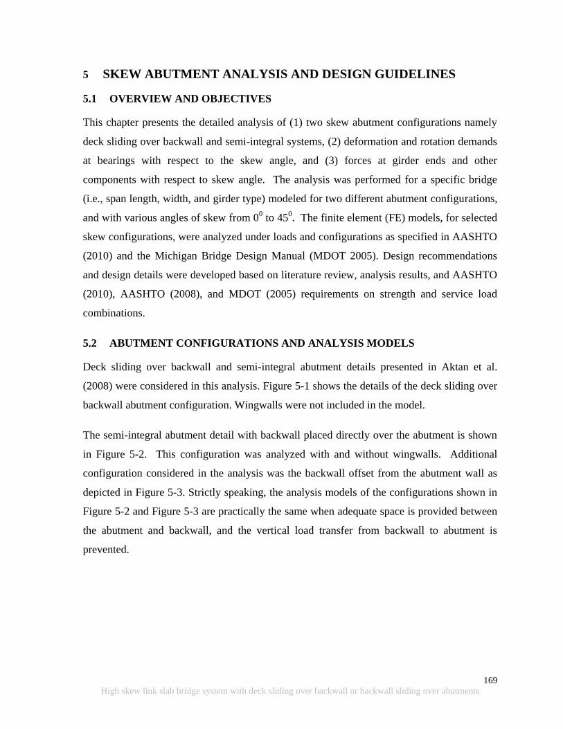
169
High skew link slab bridge system with deck sliding over backwall or backwall sliding over abutments
5 SKEW ABUTMENT ANALYSIS AND DESIGN GUIDELINES
5.1 OVERVIEW AND OBJECTIVES
This chapter presents the detailed analysis of (1) two skew abutment configurations namely
deck sliding over backwall and semi-integral systems, (2) deformation and rotation demands
at bearings with respect to the skew angle, and (3) forces at girder ends and other
components with respect to skew angle. The analysis was performed for a specific bridge
(i.e., span length, width, and girder type) modeled for two different abutment configurations,
and with various angles of skew from 00 to 45
0. The finite element (FE) models, for selected
skew configurations, were analyzed under loads and configurations as specified in AASHTO
(2010) and the Michigan Bridge Design Manual (MDOT 2005). Design recommendations
and design details were developed based on literature review, analysis results, and AASHTO
(2010), AASHTO (2008), and MDOT (2005) requirements on strength and service load
combinations.
5.2 ABUTMENT CONFIGURATIONS AND ANALYSIS MODELS
Deck sliding over backwall and semi-integral abutment details presented in Aktan et al.
(2008) were considered in this analysis. Figure 5-1 shows the details of the deck sliding over
backwall abutment configuration. Wingwalls were not included in the model.
The semi-integral abutment detail with backwall placed directly over the abutment is shown
in Figure 5-2. This configuration was analyzed with and without wingwalls. Additional
configuration considered in the analysis was the backwall offset from the abutment wall as
depicted in Figure 5-3. Strictly speaking, the analysis models of the configurations shown in
Figure 5-2 and Figure 5-3 are practically the same when adequate space is provided between
the abutment and backwall, and the vertical load transfer from backwall to abutment is
prevented.
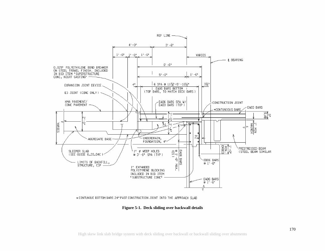
170
High skew link slab bridge system with deck sliding over backwall or backwall sliding over abutments
Figure 5-1. Deck sliding over backwall details
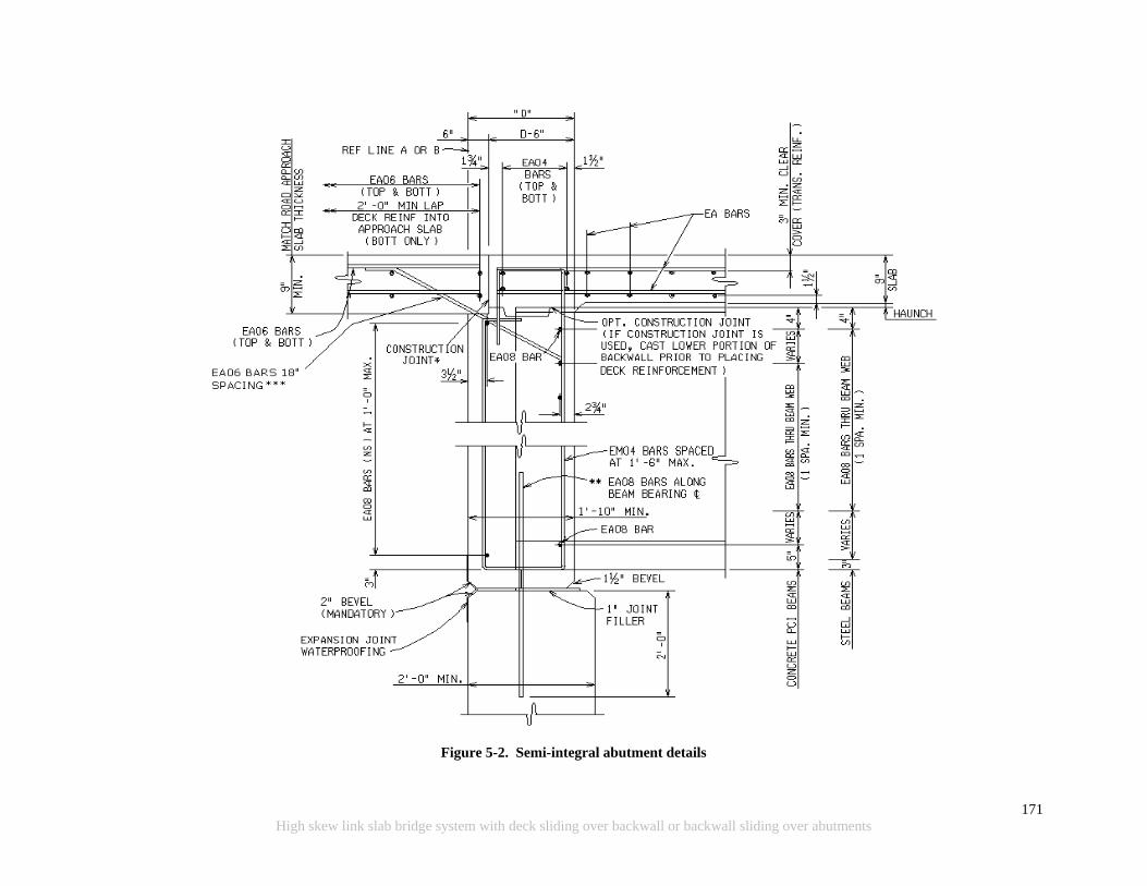
171
High skew link slab bridge system with deck sliding over backwall or backwall sliding over abutments
Figure 5-2. Semi-integral abutment details
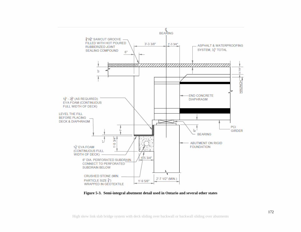
172
High skew link slab bridge system with deck sliding over backwall or backwall sliding over abutments
Figure 5-3. Semi-integral abutment detail used in Ontario and several other states
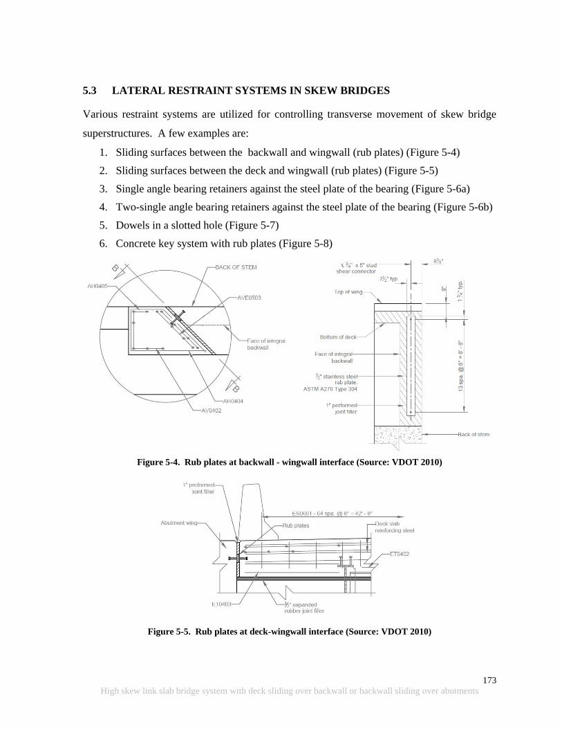
173
High skew link slab bridge system with deck sliding over backwall or backwall sliding over abutments
5.3 LATERAL RESTRAINT SYSTEMS IN SKEW BRIDGES
Various restraint systems are utilized for controlling transverse movement of skew bridge
superstructures. A few examples are:
1. Sliding surfaces between the backwall and wingwall (rub plates) (Figure 5-4)
2. Sliding surfaces between the deck and wingwall (rub plates) (Figure 5-5)
3. Single angle bearing retainers against the steel plate of the bearing (Figure 5-6a)
4. Two-single angle bearing retainers against the steel plate of the bearing (Figure 5-6b)
5. Dowels in a slotted hole (Figure 5-7)
6. Concrete key system with rub plates (Figure 5-8)
Figure 5-4. Rub plates at backwall - wingwall interface (Source: VDOT 2010)
Figure 5-5. Rub plates at deck-wingwall interface (Source: VDOT 2010)
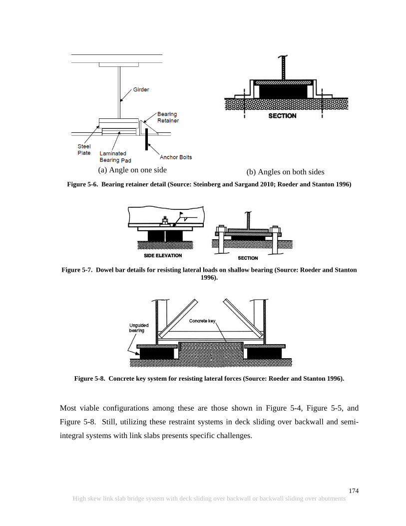
174
High skew link slab bridge system with deck sliding over backwall or backwall sliding over abutments
(a) Angle on one side
(b) Angles on both sides
Figure 5-6. Bearing retainer detail (Source: Steinberg and Sargand 2010; Roeder and Stanton 1996)
Figure 5-7. Dowel bar details for resisting lateral loads on shallow bearing (Source: Roeder and Stanton
1996).
Figure 5-8. Concrete key system for resisting lateral forces (Source: Roeder and Stanton 1996).
Most viable configurations among these are those shown in Figure 5-4, Figure 5-5, and
Figure 5-8. Still, utilizing these restraint systems in deck sliding over backwall and semi-
integral systems with link slabs presents specific challenges.

175
High skew link slab bridge system with deck sliding over backwall or backwall sliding over abutments
5.3.1 Restraint Systems at the Abutment
5.3.1.1 Deck Sliding over Backwall System
Placing rub plates between the wingwall and deck at the acute corner of the deck poses
several challenges. Rub plates should be placed on the span side of the deck with respect to
the construction joint, if transverse movement is to be a restraint at the deck level. Also, the
corner of the deck should be adequately detailed to accommodate the forces generated due to
restraint. For deck sliding over backwall system, the most promising later load restraint
system is the use of concrete key system shown in Figure 5-8.
5.3.1.2 Semi-Integral Backwall System
Semi-integral abutment details given in Figure 5-2 provide several advantages if adequate
measures are taken to prevent backfill ingress through the abutment-backwall interface and
load transfer between the backwall and abutment. A lateral movement restraint system can
be developed by using the details shown in Figure 5-4. Forces on wingwalls can be
minimized by providing transverse movement restraints at girders and/or providing EPS as a
backfill material. Similar details can be developed to restrain transverse movement of the
configuration given in Figure 5-3 by providing restraint against the diaphragm rather than the
backwall.
5.3.2 Restraint System over the Pier
Deck level restraints cannot be implemented over the pier with the link slab. In addition, the
restraint system that extends from the pier cap to the deck level has to accommodate a large
moment. Considering these, an option to restrain transverse movement of the bridge
superstructure is to provide concrete keys with a configuration similar to that shown in
Figure 5-8 .
5.4 ANALYSIS OF HIGH SKEW BRIDGE WITH DECK SLIDING OVER
BACKWALL AND SEMI-INTEGRAL ABUTMENTS
The objective of the analysis is to investigate the behavior of high skew bridge spans with
specific abutment details presented in Figure 5-1, Figure 5-2, and Figure 5-3. The analysis
results will establish the design load calculation procedures.
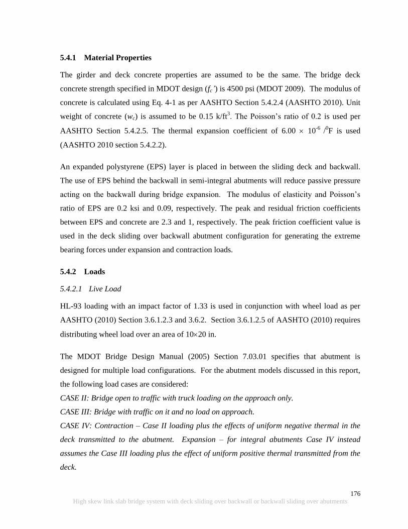
176
High skew link slab bridge system with deck sliding over backwall or backwall sliding over abutments
5.4.1 Material Properties
The girder and deck concrete properties are assumed to be the same. The bridge deck
concrete strength specified in MDOT design (fc’) is 4500 psi (MDOT 2009). The modulus of
concrete is calculated using Eq. 4-1 as per AASHTO Section 5.4.2.4 (AASHTO 2010). Unit
weight of concrete (wc) is assumed to be 0.15 k/ft3. The Poisson‟s ratio of 0.2 is used per
AASHTO Section 5.4.2.5. The thermal expansion coefficient of 6.00 10-6
/0F is used
(AASHTO 2010 section 5.4.2.2).
An expanded polystyrene (EPS) layer is placed in between the sliding deck and backwall.
The use of EPS behind the backwall in semi-integral abutments will reduce passive pressure
acting on the backwall during bridge expansion. The modulus of elasticity and Poisson‟s
ratio of EPS are 0.2 ksi and 0.09, respectively. The peak and residual friction coefficients
between EPS and concrete are 2.3 and 1, respectively. The peak friction coefficient value is
used in the deck sliding over backwall abutment configuration for generating the extreme
bearing forces under expansion and contraction loads.
5.4.2 Loads
5.4.2.1 Live Load
HL-93 loading with an impact factor of 1.33 is used in conjunction with wheel load as per
AASHTO (2010) Section 3.6.1.2.3 and 3.6.2. Section 3.6.1.2.5 of AASHTO (2010) requires
distributing wheel load over an area of 1020 in.
The MDOT Bridge Design Manual (2005) Section 7.03.01 specifies that abutment is
designed for multiple load configurations. For the abutment models discussed in this report,
the following load cases are considered:
CASE II: Bridge open to traffic with truck loading on the approach only.
CASE III: Bridge with traffic on it and no load on approach.
CASE IV: Contraction – Case II loading plus the effects of uniform negative thermal in the
deck transmitted to the abutment. Expansion – for integral abutments Case IV instead
assumes the Case III loading plus the effect of uniform positive thermal transmitted from the
deck.
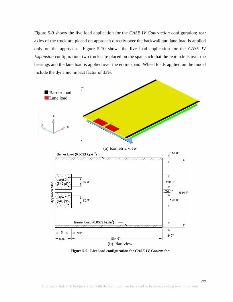
177
High skew link slab bridge system with deck sliding over backwall or backwall sliding over abutments
Figure 5-9 shows the live load application for the CASE IV Contraction configuration; rear
axles of the truck are placed on approach directly over the backwall and lane load is applied
only on the approach. Figure 5-10 shows the live load application for the CASE IV
Expansion configuration; two trucks are placed on the span such that the rear axle is over the
bearings and the lane load is applied over the entire span. Wheel loads applied on the model
include the dynamic impact factor of 33%.
Barrier load
Lane load
(a) Isometric view
(b) Plan view
Figure 5-9. Live load configuration for CASE IV Contraction
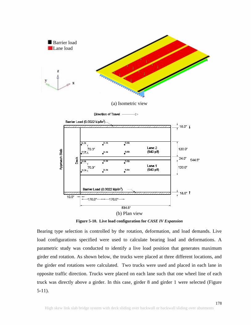
178
High skew link slab bridge system with deck sliding over backwall or backwall sliding over abutments
Barrier load
Lane load
(a) Isometric view
(b) Plan view
Figure 5-10. Live load configuration for CASE IV Expansion
Bearing type selection is controlled by the rotation, deformation, and load demands. Live
load configurations specified were used to calculate bearing load and deformations. A
parametric study was conducted to identify a live load position that generates maximum
girder end rotation. As shown below, the trucks were placed at three different locations, and
the girder end rotations were calculated. Two trucks were used and placed in each lane in
opposite traffic direction. Trucks were placed on each lane such that one wheel line of each
truck was directly above a girder. In this case, girder 8 and girder 1 were selected (Figure
5-11).

179
High skew link slab bridge system with deck sliding over backwall or backwall sliding over abutments
Truck Position 1 –the trucks were placed as near as possible to the obtuse corner of
the skew bridge (Figure 5-12). One of the rear wheels of the truck was placed
approximately on the diagonal between the obtuse corners (load path).
Truck Position 2 – the center of gravity of the trucks was placed at 1/3 of the span
measured along the lane from the obtuse corners (Figure 5-13).
Truck Position 3 – the center of gravity of the trucks was close to midspan of the
girders (Figure 5-14). The trucks were positioned at locations that generate the
maximum midspan moment of the girder.
Table 5-1 summarizes the girder 1 and 8 end rations under above stated positions of the
trucks. It is clear from the results that the girder end rotations increase as the trucks move
towards the acute corner of the bridge. Hence, Truck Position 3 was used for further analysis
in conjunction with dead and thermal gradient loads to calculate the girder end rotation.
Additionally, girder end rotation values validate that the load path is along the diagonal
between obtuse corners (i.e., the end rotation of girder 8 at the obtuse corner is larger than
girder 1 for all the load cases).
Figure 5-11. Location of girder 1 and 8 where girder end rotation was calculated
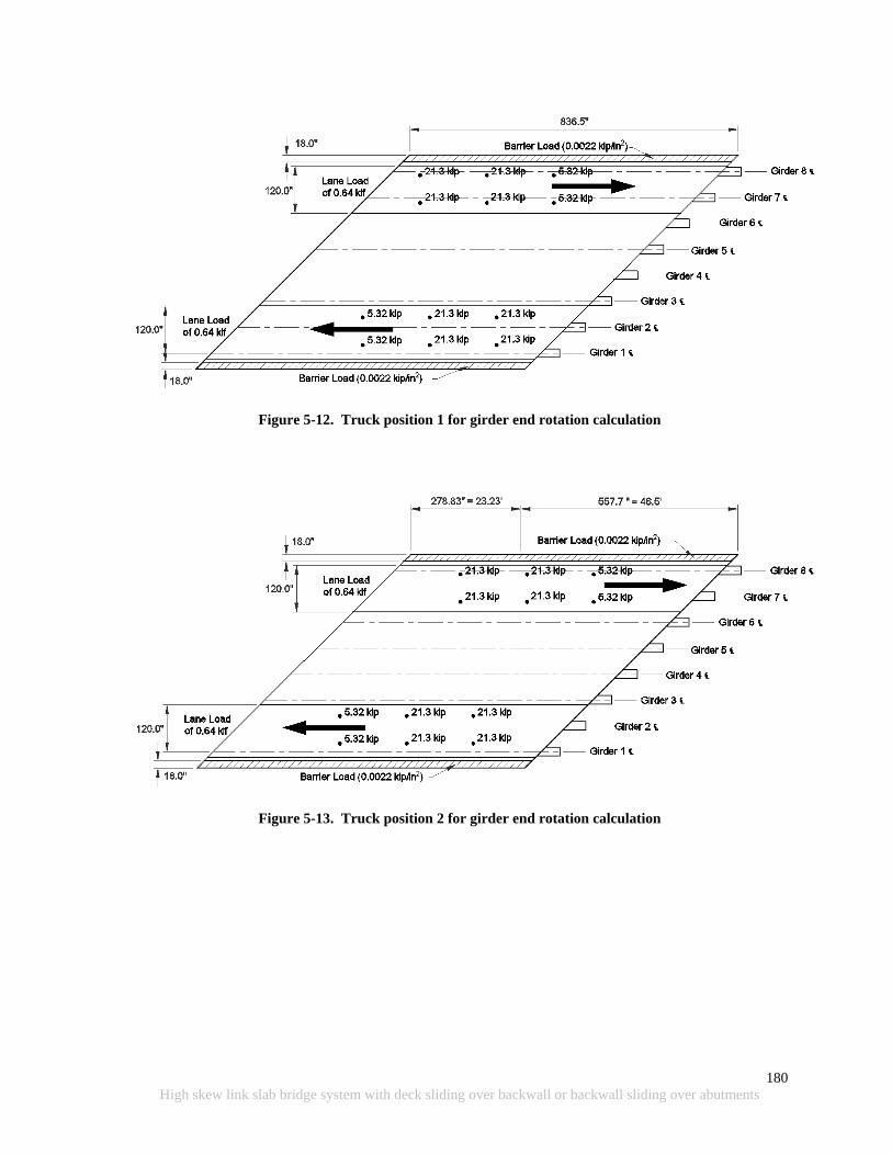
180
High skew link slab bridge system with deck sliding over backwall or backwall sliding over abutments
Figure 5-12. Truck position 1 for girder end rotation calculation
Figure 5-13. Truck position 2 for girder end rotation calculation
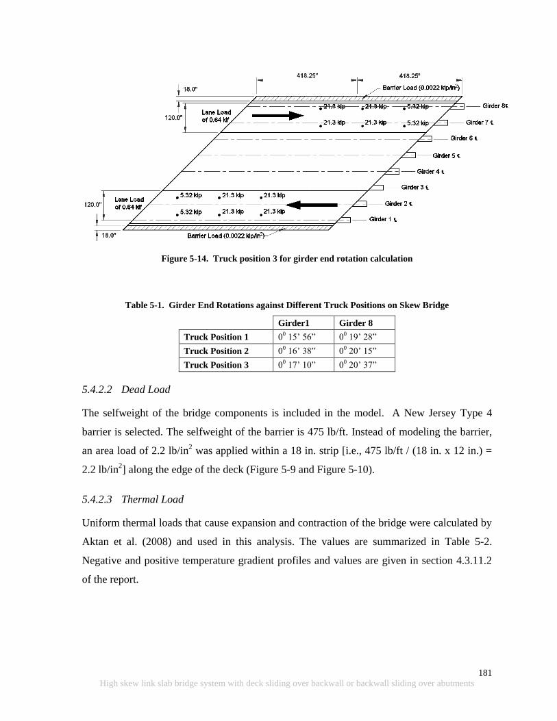
181
High skew link slab bridge system with deck sliding over backwall or backwall sliding over abutments
Figure 5-14. Truck position 3 for girder end rotation calculation
Table 5-1. Girder End Rotations against Different Truck Positions on Skew Bridge
Girder1 Girder 8
Truck Position 1 00 15‟ 56” 00 19‟ 28”
Truck Position 2 00 16‟ 38” 00 20‟ 15”
Truck Position 3 00 17‟ 10” 00 20‟ 37”
5.4.2.2 Dead Load
The selfweight of the bridge components is included in the model. A New Jersey Type 4
barrier is selected. The selfweight of the barrier is 475 lb/ft. Instead of modeling the barrier,
an area load of 2.2 lb/in2 was applied within a 18 in. strip [i.e., 475 lb/ft / (18 in. x 12 in.) =
2.2 lb/in2] along the edge of the deck (Figure 5-9 and Figure 5-10).
5.4.2.3 Thermal Load
Uniform thermal loads that cause expansion and contraction of the bridge were calculated by
Aktan et al. (2008) and used in this analysis. The values are summarized in Table 5-2.
Negative and positive temperature gradient profiles and values are given in section 4.3.11.2
of the report.
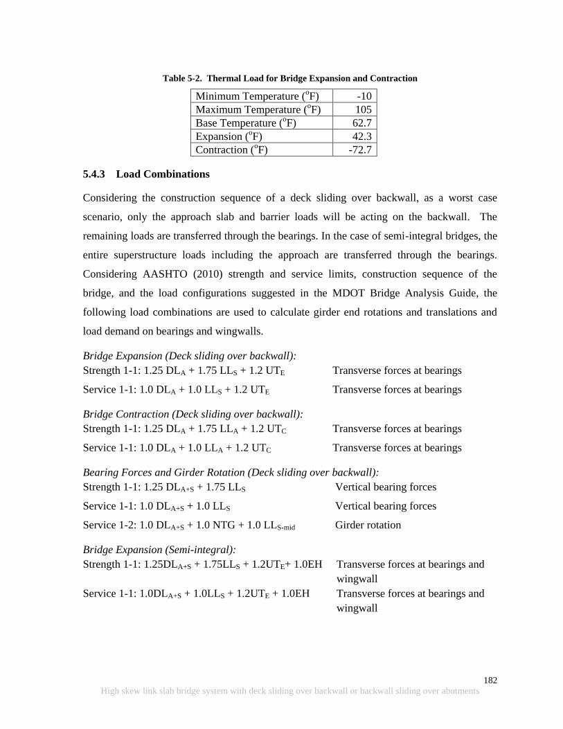
182
High skew link slab bridge system with deck sliding over backwall or backwall sliding over abutments
Table 5-2. Thermal Load for Bridge Expansion and Contraction
Minimum Temperature (oF) -10
Maximum Temperature (oF) 105
Base Temperature (oF) 62.7
Expansion (oF) 42.3
Contraction (oF) -72.7
5.4.3 Load Combinations
Considering the construction sequence of a deck sliding over backwall, as a worst case
scenario, only the approach slab and barrier loads will be acting on the backwall. The
remaining loads are transferred through the bearings. In the case of semi-integral bridges, the
entire superstructure loads including the approach are transferred through the bearings.
Considering AASHTO (2010) strength and service limits, construction sequence of the
bridge, and the load configurations suggested in the MDOT Bridge Analysis Guide, the
following load combinations are used to calculate girder end rotations and translations and
load demand on bearings and wingwalls.
Bridge Expansion (Deck sliding over backwall):
Strength 1-1: 1.25 DLA + 1.75 LLS + 1.2 UTE Transverse forces at bearings
Service 1-1: 1.0 DLA + 1.0 LLS + 1.2 UTE Transverse forces at bearings
Bridge Contraction (Deck sliding over backwall):
Strength 1-1: 1.25 DLA + 1.75 LLA + 1.2 UTC Transverse forces at bearings
Service 1-1: 1.0 DLA + 1.0 LLA + 1.2 UTC Transverse forces at bearings
Bearing Forces and Girder Rotation (Deck sliding over backwall):
Strength 1-1: 1.25 DLA+S + 1.75 LLS Vertical bearing forces
Service 1-1: 1.0 DLA+S + 1.0 LLS Vertical bearing forces
Service 1-2: 1.0 DLA+S + 1.0 NTG + 1.0 LLS-mid Girder rotation
Bridge Expansion (Semi-integral):
Strength 1-1: 1.25DLA+S + 1.75LLS + 1.2UTE+ 1.0EH Transverse forces at bearings and
wingwall
Service 1-1: 1.0DLA+S + 1.0LLS + 1.2UTE + 1.0EH Transverse forces at bearings and
wingwall

183
High skew link slab bridge system with deck sliding over backwall or backwall sliding over abutments
Bridge Contraction (Semi-integral):
Strength 1-1: 1.25DLA+S +1.75LLA +1.2 UTC+ 1.0EH Transverse forces at bearings and
wingwall
Service 1-1: 1.0DLA+S + 1.0 LLA + 1.2 UTC+ 1.0EH Transverse forces at bearings and
wingwall
Bearing Forces and Girder Rotation (Semi-integral):
Strength 1-1: 1.25DLA+S + 1.75LLS Vertical bearing forces
Service 1-1: 1.0DLA+S + 1.0LLS Vertical bearing forces
Service 1-2: 1.0DLA+S + 1.0NTG + 1.0 LLS-mid Girder rotation
Where DLA – Dead load of approach
DLA+S – Dead load of the entire superstructure including the approach
EH – Earth pressure
LLA – Live load on approach (Figure 5-9)
LLS – Live load on span (Figure 5-10)
LLS-mid – Live load for maximum girder rotation
NTG – Negative temperature gradient
UTC – Uniform temperature - contraction
UTE – Uniform temperature - expansion
5.4.4 Boundary Conditions
An ideal boundary condition was used with all the abutment configurations. Ideal boundary
condition generates maximum translations and rotations at the bearings. Bearing translations
over the abutments are restricted to the bridge‟s longitudinal axis. Hence, reaction forces are
developed in transverse and vertical directions and will be useful for bearing and girder end
restraint design. In models with deck sliding over backwall configuration, friction between
EPS and approach was included. Semi-integral models were analyzed with and without
wingwalls to evaluate the forces at the bearings. As a worst case representation, transverse
bearing restraint at the abutment is removed in order to calculate the maximum force on the
wingwall. Further, forces at the wingwall are calculated with respect to the skew angle of the
deck. The sliding surface between the deck and the wingwall is assumed friction free.
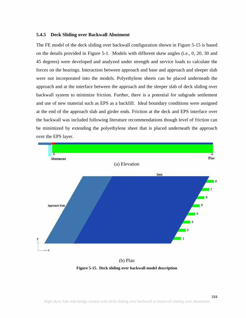
184
High skew link slab bridge system with deck sliding over backwall or backwall sliding over abutments
5.4.5 Deck Sliding over Backwall Abutment
The FE model of the deck sliding over backwall configuration shown in Figure 5-15 is based
on the details provided in Figure 5-1. Models with different skew angles (i.e., 0, 20, 30 and
45 degrees) were developed and analyzed under strength and service loads to calculate the
forces on the bearings. Interaction between approach and base and approach and sleeper slab
were not incorporated into the models. Polyethylene sheets can be placed underneath the
approach and at the interface between the approach and the sleeper slab of deck sliding over
backwall system to minimize friction. Further, there is a potential for subgrade settlement
and use of new material such as EPS as a backfill. Ideal boundary conditions were assigned
at the end of the approach slab and girder ends. Friction at the deck and EPS interface over
the backwall was included following literature recommendations though level of friction can
be minimized by extending the polyethylene sheet that is placed underneath the approach
over the EPS layer.
(a) Elevation
(b) Plan
Figure 5-15. Deck sliding over backwall model description
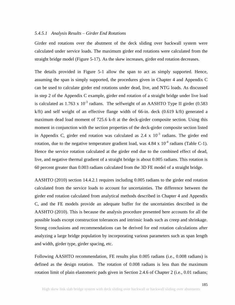
185
High skew link slab bridge system with deck sliding over backwall or backwall sliding over abutments
5.4.5.1 Analysis Results – Girder End Rotations
Girder end rotations over the abutment of the deck sliding over backwall system were
calculated under service loads. The maximum girder end rotations were calculated from the
straight bridge model (Figure 5-17). As the skew increases, girder end rotation decreases.
The details provided in Figure 5-1 allow the span to act as simply supported. Hence,
assuming the span is simply supported, the procedures given in Chapter 4 and Appendix C
can be used to calculate girder end rotations under dead, live, and NTG loads. As discussed
in step 2 of the Appendix C example, girder end rotation of a straight bridge under live load
is calculated as 1.763 x 10⁻³
radians. The selfweight of an AASHTO Type II girder (0.583
k/ft) and self weight of an effective flange width of 66-in. deck (0.619 k/ft) generated a
maximum dead load moment of 725.6 k-ft at the deck-girder composite section. Using this
moment in conjunction with the section properties of the deck-girder composite section listed
in Appendix C, girder end rotation was calculated as 2.4 x 10⁻³
radians. The girder end
rotation, due to the negative temperature gradient load, was 4.84 x 10⁻⁴
radians (Table C-1).
Hence the service rotation calculated at the girder end due to the combined effect of dead,
live, and negative thermal gradient of a straight bridge is about 0.005 radians. This rotation is
60 percent greater than 0.003 radians calculated from the 3D FE model of a straight bridge.
AASHTO (2010) section 14.4.2.1 requires including 0.005 radians to the girder end rotation
calculated from the service loads to account for uncertainties. The difference between the
girder end rotation calculated from analytical methods described in Chapter 4 and Appendix
C, and the FE models provide an adequate buffer for the uncertainties described in the
AASHTO (2010). This is because the analysis procedure presented here accounts for all the
possible loads except construction tolerances and intrinsic loads such as creep and shrinkage.
Strong conclusions and recommendations can be derived for end rotation calculations after
analyzing a large bridge population by incorporating various parameters such as span length
and width, girder type, girder spacing, etc.
Following AASHTO recommendation, FE results plus 0.005 radians (i.e., 0.008 radians) is
defined as the design rotation. The rotation of 0.008 radians is less than the maximum
rotation limit of plain elastomeric pads given in Section 2.4.6 of Chapter 2 (i.e., 0.01 radians;
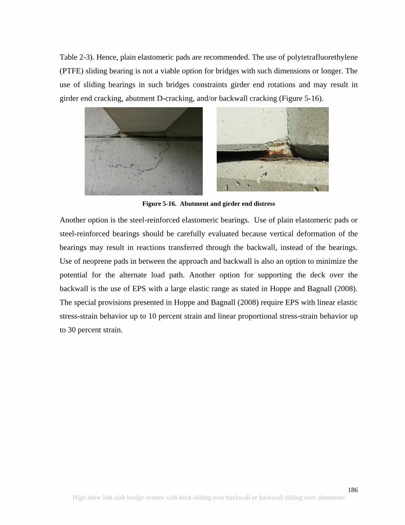
186
High skew link slab bridge system with deck sliding over backwall or backwall sliding over abutments
Table 2-3). Hence, plain elastomeric pads are recommended. The use of polytetrafluorethylene
(PTFE) sliding bearing is not a viable option for bridges with such dimensions or longer. The
use of sliding bearings in such bridges constraints girder end rotations and may result in
girder end cracking, abutment D-cracking, and/or backwall cracking (Figure 5-16).
Figure 5-16. Abutment and girder end distress
Another option is the steel-reinforced elastomeric bearings. Use of plain elastomeric pads or
steel-reinforced bearings should be carefully evaluated because vertical deformation of the
bearings may result in reactions transferred through the backwall, instead of the bearings.
Use of neoprene pads in between the approach and backwall is also an option to minimize the
potential for the alternate load path. Another option for supporting the deck over the
backwall is the use of EPS with a large elastic range as stated in Hoppe and Bagnall (2008).
The special provisions presented in Hoppe and Bagnall (2008) require EPS with linear elastic
stress-strain behavior up to 10 percent strain and linear proportional stress-strain behavior up
to 30 percent strain.
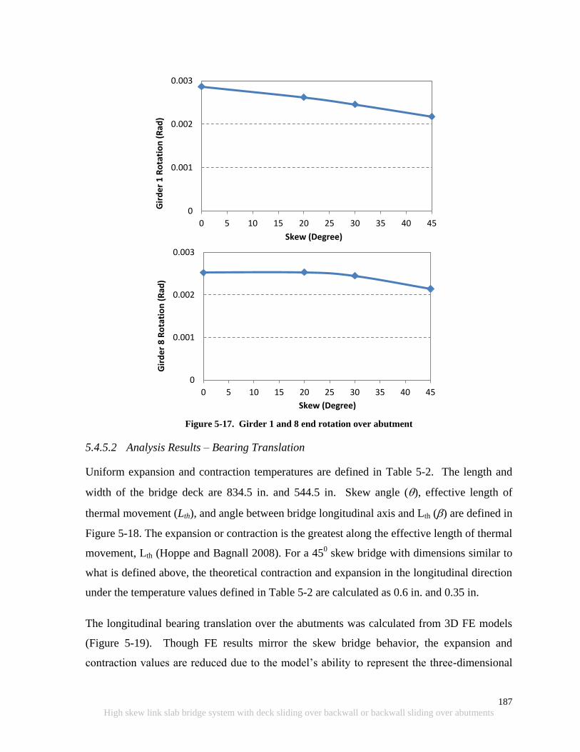
187
High skew link slab bridge system with deck sliding over backwall or backwall sliding over abutments
Figure 5-17. Girder 1 and 8 end rotation over abutment
5.4.5.2 Analysis Results – Bearing Translation
Uniform expansion and contraction temperatures are defined in Table 5-2. The length and
width of the bridge deck are 834.5 in. and 544.5 in. Skew angle (), effective length of
thermal movement (Lth), and angle between bridge longitudinal axis and Lth () are defined in
Figure 5-18. The expansion or contraction is the greatest along the effective length of thermal
movement, Lth (Hoppe and Bagnall 2008). For a 450 skew bridge with dimensions similar to
what is defined above, the theoretical contraction and expansion in the longitudinal direction
under the temperature values defined in Table 5-2 are calculated as 0.6 in. and 0.35 in.
The longitudinal bearing translation over the abutments was calculated from 3D FE models
(Figure 5-19). Though FE results mirror the skew bridge behavior, the expansion and
contraction values are reduced due to the model‟s ability to represent the three-dimensional
0
0.001
0.002
0.003
0 5 10 15 20 25 30 35 40 45
Gir
de
r 1
Ro
tati
on
(R
ad)
Skew (Degree)
0
0.001
0.002
0.003
0 5 10 15 20 25 30 35 40 45
Gir
de
r 8
Ro
tati
on
(R
ad)
Skew (Degree)
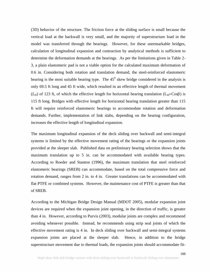
188
High skew link slab bridge system with deck sliding over backwall or backwall sliding over abutments
(3D) behavior of the structure. The friction force at the sliding surface is small because the
vertical load at the backwall is very small, and the majority of superstructure load in the
model was transferred through the bearings. However, for these unremarkable bridges,
calculation of longitudinal expansion and contraction by analytical methods is sufficient to
determine the deformation demands at the bearings. As per the limitations given in Table 2-
3, a plain elastomeric pad is not a viable option for the calculated maximum deformation of
0.6 in. Considering both rotation and translation demand, the steel-reinforced elastomeric
bearing is the most suitable bearing type. The 450 skew bridge considered in the analysis is
only 69.5 ft long and 45 ft wide, which resulted in an effective length of thermal movement
(Lth) of 123 ft, of which the effective length for horizontal bearing translation (LthCos) is
115 ft long. Bridges with effective length for horizontal bearing translation greater than 115
ft will require reinforced elastomeric bearings to accommodate rotation and deformation
demands. Further, implementation of link slabs, depending on the bearing configuration,
increases the effective length of longitudinal expansion.
The maximum longitudinal expansion of the deck sliding over backwall and semi-integral
systems is limited by the effective movement rating of the bearings or the expansion joints
provided at the sleeper slab. Published data on preliminary bearing selection shows that the
maximum translation up to 5 in. can be accommodated with available bearing types.
According to Roeder and Stanton (1996), the maximum translation that steel reinforced
elastomeric bearings (SREB) can accommodate, based on the total compressive force and
rotation demand, ranges from 2 in. to 4 in. Greater translations can be accommodated with
flat PTFE or combined systems. However, the maintenance cost of PTFE is greater than that
of SREB.
According to the Michigan Bridge Design Manual (MDOT 2005), modular expansion joint
devices are required when the expansion joint opening, in the direction of traffic, is greater
than 4 in. However, according to Purvis (2003), modular joints are complex and recommend
avoiding whenever possible. Instead, he recommends using strip seal joints of which the
effective movement rating is 4 in. In deck sliding over backwall and semi-integral systems
expansion joints are placed at the sleeper slab. Hence, in addition to the bridge
superstructure movement due to thermal loads, the expansion joints should accommodate fit-

189
High skew link slab bridge system with deck sliding over backwall or backwall sliding over abutments
in tolerances, approach slab expansion/contraction, deformation of substructure due
construction loads and sequence, and superstructure deformations due to creep and shrinkage
in prestressed girders and selfweight. When strip seals are used, it is reasonable to assume
available expansion range of 3 in. at the joint to accommodate thermal movement of a bridge
superstructure.
According to published data, performance of expansion joints is well below expected (Purvis
2003). Further, expansion joint maintenance and replacement cost is much greater than that
of bearings due to shorter service life of joints. Hence, expansion joint effective movement
rating should be considered when bridge expansion length is specified. Bridge expansion
length (i.e., L in Figure 5-18) is defined as the distance along the longitudinal axis measured
from abutment to the nearest fixed bearing.
Bridge expansion length recommendations are developed considering width and skew ranges
of single span steel and prestressed concrete bridges under the MDOT jurisdiction as shown
in Figure 5-20 and Figure 5-21. Also assumed are a maximum strip seal joint width of 3 in.,
and an expansion and contraction thermal load of 115 0F. For example, from Figure 5-20, a
straight concrete bridge superstructure expansion length should not exceed 300 ft. For a 450
skew concrete bridge of 100 ft wide superstructure expansion length should be limited to 200
ft. From Figure 5-21, when steel girder bridges are considered, expansion length should not
exceed 275 ft for straight and 175 ft for a 100 ft wide 450 skew bridge (Figure 5-21).
On the other hand, transverse deformations of a bridge under uniform expansion and
contraction thermal loads are only a function of the bridge width. Bridge width is measured
perpendicular to the longitudinal axis of the bridge. The girder deformations and associated
forces developed in a skew system due to transverse bearing restraint can be minimized by
increasing bearing fit-in tolerances. As an example, when bearings are arranged in such a
way that a bridge is allowed to expand in the transverse direction symmetrical to the
longitudinal axis, a maximum of 0.5 in transverse movement can be expected under the
exterior girder bearing of a 100 ft wide steel or concrete bridge that is exposed to a 115 0F
expansion and contraction thermal range.
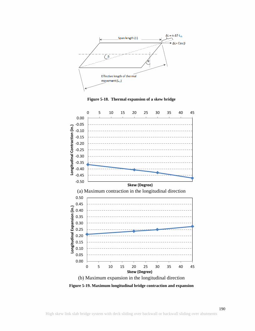
190
High skew link slab bridge system with deck sliding over backwall or backwall sliding over abutments
Figure 5-18. Thermal expansion of a skew bridge
(a) Maximum contraction in the longitudinal direction
(b) Maximum expansion in the longitudinal direction
Figure 5-19. Maximum longitudinal bridge contraction and expansion
-0.50
-0.45
-0.40
-0.35
-0.30
-0.25
-0.20
-0.15
-0.10
-0.05
0.00
0 5 10 15 20 25 30 35 40 45
Lon
gitu
din
al C
on
trac
tio
n (
in.)
Skew (Degree)
0.00
0.05
0.10
0.15
0.20
0.25
0.30
0.35
0.40
0.45
0.50
0 5 10 15 20 25 30 35 40 45
Lon
gitu
din
al E
xpan
sio
n (
in.)
Skew (Degree)
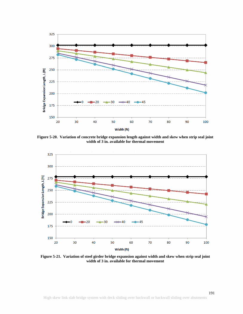
191
High skew link slab bridge system with deck sliding over backwall or backwall sliding over abutments
Figure 5-20. Variation of concrete bridge expansion length against width and skew when strip seal joint
width of 3 in. available for thermal movement
Figure 5-21. Variation of steel girder bridge expansion against width and skew when strip seal joint
width of 3 in. available for thermal movement
192
High skew link slab bridge system with deck sliding over backwall or backwall sliding over abutments
5.4.5.3 Analysis Results – Vertical Bearing Forces
Bridge FE models were analyzed under the critical service load combination that generates
the maximum vertical bearing forces. Results shown in Figure 5-22 show that the bridge
response duplicates the skew behavior of a simple span, where girder end reactions reduce
under the acute corner and increase under the obtuse corner with increasing skew. Vertical
forces that develop on the bearing of this particular bridge are not a concern for any of the
bearing types up to a 450 skew. This is because the maximum load recommended for a plain
elastomeric pad, which is the lowest among other bearing types, is 100 kips. The two-lane
bridge considered in the analysis is only 69.5 ft long. As the bridge length increases, the load
demand on bearings will increase. Especially, the load demand on the bearings underneath
the obtuse corner of wide high skew bridges will increase dramatically. Considering all these
factors, reinforced elastomeric bearings are recommended for skew deck sliding over
backwall configurations. This recommendation is supported by the translation and rotation
demands presented in previous sections. Hence, the designer can use the simple span model
to calculate the reactions and deformations of the bridge with deck sliding over backwall for
the bearing design.

193
High skew link slab bridge system with deck sliding over backwall or backwall sliding over abutments
(a) Girder 1 vertical reaction variation over abutment and pier
(b) Girder 8 vertical reaction variation over abutment and pier
Figure 5-22. Girder 1 and 8 reaction variation over the abutment and pier
5.4.5.4 Analysis Results – Transverse Bearing Forces at Abutment
Transverse bearing forces were calculated at each bearing over the abutment under strength
load combinations that include thermal contraction loads (Figure 5-23). Similarly, transverse
bearing forces were calculated at each bearing over the abutment under strength load
combinations that include thermal expansion loads (Figure 5-24). In both cases, no other
transverse restraints were considered. As shown in the figures, in the transverse direction,
thermal contraction generates the greatest forces on bearings. According to AASHTO LRFD
(2010) section 14.7.9 guides and restraints shall be designed using strength limit state load
0
20
40
60
80
100
120
0 10 20 30 40 50
Ve
rtic
al r
eac
tio
n (
kip
)
Skew (deg.)
At Abutment
At Pier
0
20
40
60
80
100
120
0 10 20 30 40 50
Ve
rtic
al r
eac
tio
n (
kip
)
Skew (deg.)
At Abutment
At Pier
194
High skew link slab bridge system with deck sliding over backwall or backwall sliding over abutments
combinations for the larger of either (a) the factored horizontal design force or (b) 10
percent of the total factored vertical force acting on all the bearings at the bent divided by
the number of guided bearings at the bent. Though the AASHTO recommendation is for the
bearings over the bent, this can also be applied to the design of bearings over the abutment of
the deck sliding over backwall configuration since there is no backfill pressure effect on the
structure. The total vertical force on the abutment bearings that was calculated from strength
load combinations is 1000 kips. According to AASHTO, if two girder ends are restrained in
the transverse direction, the design load is 50 kips which is less than the 10% of the forces
generated under thermal loads.
The bearing forces shown in Figure 5-23 and Figure 5-24 were calculated without any
allowance for bearing movement in the transverse direction. Transverse bearing forces can be
minimized or eliminated by increasing fit-in tolerances between position dowel and the sole
plate. This is a practical solution for the deck sliding over backwall system once the friction
at interfaces between approach-EPS, approach-base, and approach-sleeper slab is minimized
by providing a polyethylene sheet. Bridge plans generally require a 0.125 in. fit-in tolerance
between the position dowel bar and the slot in the sole plate (Figure 5-25). Further,
AASHTO LRFD Bridge Construction Specification (2008) provides manufacturing and
installation tolerances. With the tolerances achieved during manufacturing and installation,
there is a great possibility of the total transverse force not being equally shared by all of the
bearings. Providing adequate tolerance for transverse movement of the bearings and
constraining a single or a two middle girder ends should be considered. The transverse
expansion of a 40 ft wide concrete bridge under differential uniform thermal load of 80 0F is
about 0.23 in. whereas the allowable tolerance specified in the specifications is 0.125 in.
Most of the analysis and design examples in the literature have dealt with other structural
systems such as semi-integral or integral abutments that are subjected to thermal expansion
loads. This is because the passive earth pressure built up at the backwall tends to rotate the
superstructure and increases the bearing forces than those developed under contraction
thermal loads. In the case of deck sliding over backwall, for expansion thermal loads, only
restrain force is from the interface friction which can be minimized as suggested above.
195
High skew link slab bridge system with deck sliding over backwall or backwall sliding over abutments
Implementation of some of the bearing configurations discussed in Chapter 2 section 2.3 can
release girder end forces developed under thermal expansion and contraction loads. Because
of the link slab over the pier, the only possible bearing configuration is the radial from center
(Figure 2-17 c). The recommendation is to restrain the transverse movement of the middle
girder end (if odd number of girders) or two middle girder ends (if even number of girders)
using concrete keys with rub plates (shown in Figure 5-8) and to increase the tolerance of the
slot in the sole plate and bearing to accommodate transverse movement of unrestrained girder
ends. Once the middle girder(s) is restrained in the transverse direction, the transverse
movement the bearing needs to accommodate is proportional to only half of the bridge width.
For example, the required tolerance for a 40 ft wide bridge under differential uniform thermal
load of 80 0F is about 0.12 in. This is less than the allowable tolerance of 0.125 in.
recommended for the position dowels by the AASHTO LRFD Bridge Construction
Specification (2008).
It is recommended the maximum bearing tolerance in the transverse direction is limited to
0.25 in. until further investigations are carried out investigating the impact of the increased fit
tolerances on the girder position dowels on the rest of the bridge components. The maximum
limit was established as the summation of fit-in tolerance provided with general bearing
details (Figure 5-25) and the AASHTO Bridge Construction Specification tolerance of
|+0.125| or |-0.125| in.
Further, friction at the approach-EPS, approach-base, and approach-sleeper slab has a great
influence on link slab stresses. The analysis discussed in Chapter 4 used three different
support configurations, HRRR, RRHR, and RHHR, where H and R represent hinge (i.e.,
fixed bearing) and roller (i.e., expansion bearing). In the case of HRRR, the bearings
underneath the link slab are expansion bearings (R) while the bearings over the abutments are
fixed (H) and expansion (R) types. If large frictional forces develop at the approach of the
abutment with expansion bearings, large stresses will develop at the link slab. This is
because the restrains that develop at the supports will result in an HRRR support system to
approach HRRH. As discussed, this support configuration is not recommended for link slab
bridges. In order to reduce the friction forces, providing a polyethylene sheet underneath the
entire surface of the approach is recommended (MnDOT 2011). Reducing the friction force
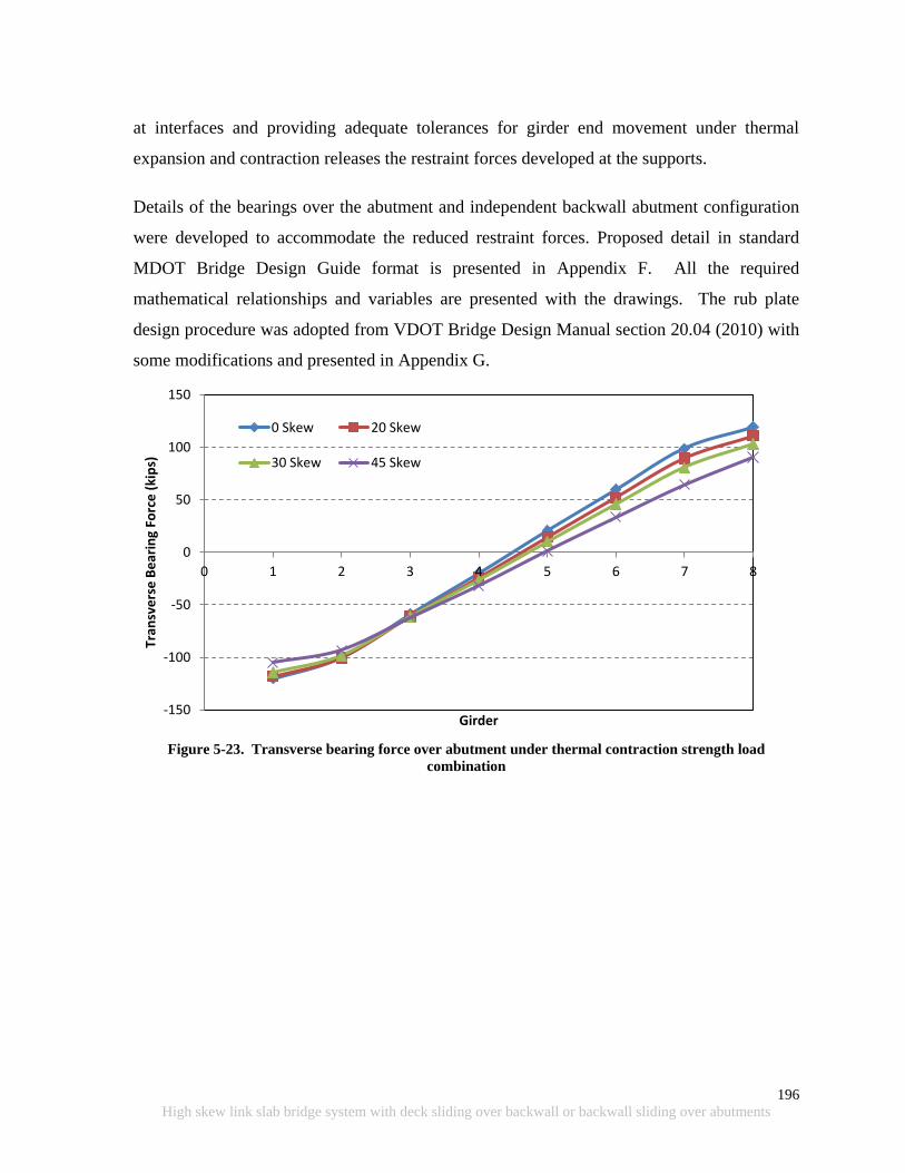
196
High skew link slab bridge system with deck sliding over backwall or backwall sliding over abutments
at interfaces and providing adequate tolerances for girder end movement under thermal
expansion and contraction releases the restraint forces developed at the supports.
Details of the bearings over the abutment and independent backwall abutment configuration
were developed to accommodate the reduced restraint forces. Proposed detail in standard
MDOT Bridge Design Guide format is presented in Appendix F. All the required
mathematical relationships and variables are presented with the drawings. The rub plate
design procedure was adopted from VDOT Bridge Design Manual section 20.04 (2010) with
some modifications and presented in Appendix G.
Figure 5-23. Transverse bearing force over abutment under thermal contraction strength load
combination
-150
-100
-50
0
50
100
150
0 1 2 3 4 5 6 7 8
Tran
sve
rse
Be
arin
g Fo
rce
(ki
ps)
Girder
0 Skew 20 Skew
30 Skew 45 Skew
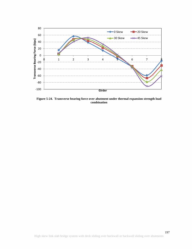
197
High skew link slab bridge system with deck sliding over backwall or backwall sliding over abutments
Figure 5-24. Transverse bearing force over abutment under thermal expansion strength load
combination
-100
-80
-60
-40
-20
0
20
40
60
80
0 1 2 3 4 5 6 7 8
Tran
sve
rse
Be
arin
g Fo
rce
(ki
ps)
Girder
0 Skew 20 Skew
30 Skew 45 Skew
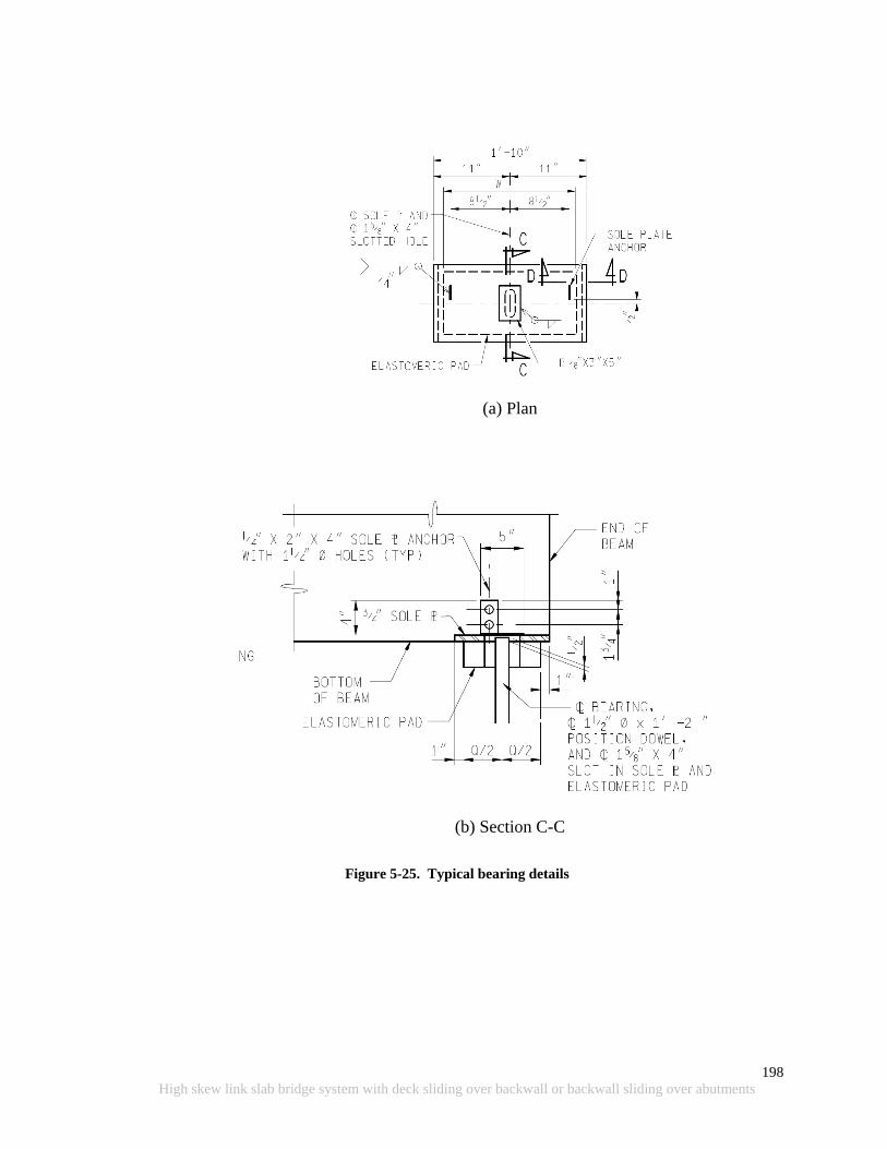
198
High skew link slab bridge system with deck sliding over backwall or backwall sliding over abutments
(a) Plan
(b) Section C-C
Figure 5-25. Typical bearing details
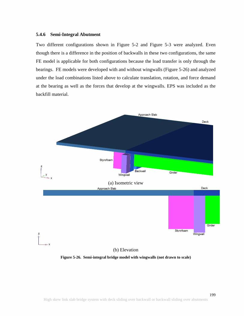
199
High skew link slab bridge system with deck sliding over backwall or backwall sliding over abutments
5.4.6 Semi-Integral Abutment
Two different configurations shown in Figure 5-2 and Figure 5-3 were analyzed. Even
though there is a difference in the position of backwalls in these two configurations, the same
FE model is applicable for both configurations because the load transfer is only through the
bearings. FE models were developed with and without wingwalls (Figure 5-26) and analyzed
under the load combinations listed above to calculate translation, rotation, and force demand
at the bearing as well as the forces that develop at the wingwalls. EPS was included as the
backfill material.
(a) Isometric view
(b) Elevation
Figure 5-26. Semi-integral bridge model with wingwalls (not drawn to scale)
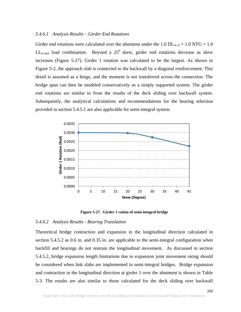
200
High skew link slab bridge system with deck sliding over backwall or backwall sliding over abutments
5.4.6.1 Analysis Results – Girder End Rotations
Girder end rotations were calculated over the abutment under the 1.0 DLA+S + 1.0 NTG + 1.0
LLS-mid load combination. Beyond a 250
skew, girder end rotations decrease as skew
increases (Figure 5-27). Girder 1 rotation was calculated to be the largest. As shown in
Figure 5-2, the approach slab is connected to the backwall by a diagonal reinforcement. This
detail is assumed as a hinge, and the moment is not transferred across the connection. The
bridge span can then be modeled conservatively as a simply supported system. The girder
end rotations are similar to from the results of the deck sliding over backwall system.
Subsequently, the analytical calculations and recommendations for the bearing selection
provided in section 5.4.5.1 are also applicable for semi-integral system.
Figure 5-27. Girder 1 ration of semi-integral bridge
5.4.6.2 Analysis Results - Bearing Translation
Theoretical bridge contraction and expansion in the longitudinal direction calculated in
section 5.4.5.2 as 0.6 in. and 0.35 in. are applicable to the semi-integral configuration when
backfill and bearings do not restrain the longitudinal movement. As discussed in section
5.4.5.2, bridge expansion length limitations due to expansion joint movement rating should
be considered when link slabs are implemented in semi-integral bridges. Bridge expansion
and contraction in the longitudinal direction at girder 1 over the abutment is shown in Table
5-3. The results are also similar to those calculated for the deck sliding over backwall
0.0000
0.0005
0.0010
0.0015
0.0020
0.0025
0.0030
0.0035
0 5 10 15 20 25 30 35 40 45
Gir
de
r 1
Ro
tati
on
(R
ad)
Skew (Degree)

201
High skew link slab bridge system with deck sliding over backwall or backwall sliding over abutments
configuration. The idealized boundary conditions were assumed in order to calculate the
maximum beam end translations. The FE model includes EPS backfill material but provides
very limited constraint to the expansion of the structure due to its low stiffness (Kp = /(1 +
); = 0.09; Kp = 0.08). The difference in analytical and 3D analysis is due to the 3
dimensional effects as discussed in section 5.4.5.2. The model without wingwalls slightly
overestimates the deformations due to the uncontrolled movement of the deck.
Hoppe and Bagnall (2008) indicated that to minimize forces on the backwall and wingwalls,
EPS with desired properties can be procured for placement at the backwall by incorporating
special provisions to the project documentations. The Virginia DOT has developed special
provisions for inclusion of EPS and geotextile. These special provisions are provided in
Hoppe and Bagnall (2008).
Table 5-3. Expansion and Contraction of Girder 1 End over Semi-Integral Abutment
FE Model
Without Wingwall With Wingwall
Skew ∆x (in.) ∆x (in.)
Co
ntr
act
ion
0 -0.36 -0.37
20 -0.40 -0.40
30 -0.42 -0.42
45 -0.49 -0.45
Ex
pa
nsi
on
0 0.21 0.21
20 0.23 0.25
30 0.24 0.26
45 0.26 0.27
5.4.6.3 Analysis Results – Transverse Bearing and Wingwall Forces at Abutment
Transverse bearing forces were calculated at each bearing over the abutment under strength
load combinations that include thermal contraction loads (Figure 5-28). Similarly, transverse
bearing forces were calculated at each bearing over the abutment under strength load
combinations that include thermal expansion loads (Figure 5-29). In both cases, no other
transverse restraints on the bridge deck were considered. As shown in the figures, thermal
contraction generates the largest force on bearings in the transverse direction in the absence
of backfill pressure under expansion loads. The forces are developed due to expansion or
contraction in the transverse direction because of girder restraints in that direction. These

202
High skew link slab bridge system with deck sliding over backwall or backwall sliding over abutments
forces are generated when supports do not accommodate transverse movement. These forces
are much greater than the ones developed in the deck sliding over backwall system with
similar dimensions. This is mainly due to the expansion and contraction of the stiff concrete
mass consisting of the backwall at the girder end.
As discussed earlier, according to AASHTO LRFD Bridge Construction Specifications
(2008), construction and manufacturing tolerances are specified up to 0.125 in.
Incorporating the tolerances, the forces developed at the girder ends, especially under thermal
contraction loads, will be reduced. Transverse forces under thermal contraction can be
reduced substantially by specifying an increased tolerance for transverse movement.
However, thermal expansion also develops bearing forces due to backfill pressure. This
backfill pressure effect can be minimized by using an EPS layer in between the backwall and
the backfill. EPS is a very soft material, and the passive pressure coefficient can be as low as
Kp = 0.08 (see section 5.4.6.2). After monitoring a 450 skew bridge for about two years,
Hoppe and Bagnall (2008) estimated Kp to be 1.2, which is much lower than the VDOT
(2010) recommended value of Kp = 4. After all, the benefits of inclusion of an EPS layer are
obvious and have a great potential to minimize the forces developed in the transverse
restraint systems of skew bridges.
Three dimensional models were analyzed under thermal expansion loads to calculate
transverse forces on the wingwall. Transverse restraint at the bearings over the abutment was
released to calculate the resultant force on the wingwall. EPS with Kp of 0.08 was used as
the backfill. The resultant wingwall force variation with skew is presented in Figure 5-30.
The calculated force on the wingwall is smaller than the values presented in literature for
different backfill material. For this reason, using an EPS layer in between the backwall and
backfill material and providing adequate tolerances at the bearings over the abutment is
recommended to release girder end forces that are developed under uniform thermal loads. It
is also recommended to use geotextile filter fabric in between EPS and backfill for
protection. Due to lack of data on passive pressure coefficient of EPS, it is recommended to
use the values suggested in VDOT (2010), i.e., Kp = 4, for design. Further, due to lack of
guidelines, the equation given in VDOT (2010) section 20-06-6 can be used to calculate EPS
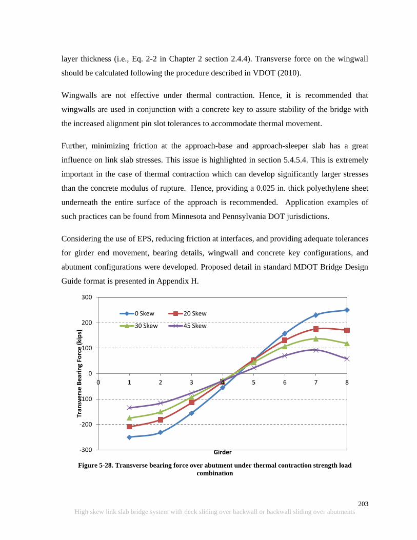
203
High skew link slab bridge system with deck sliding over backwall or backwall sliding over abutments
layer thickness (i.e., Eq. 2-2 in Chapter 2 section 2.4.4). Transverse force on the wingwall
should be calculated following the procedure described in VDOT (2010).
Wingwalls are not effective under thermal contraction. Hence, it is recommended that
wingwalls are used in conjunction with a concrete key to assure stability of the bridge with
the increased alignment pin slot tolerances to accommodate thermal movement.
Further, minimizing friction at the approach-base and approach-sleeper slab has a great
influence on link slab stresses. This issue is highlighted in section 5.4.5.4. This is extremely
important in the case of thermal contraction which can develop significantly larger stresses
than the concrete modulus of rupture. Hence, providing a 0.025 in. thick polyethylene sheet
underneath the entire surface of the approach is recommended. Application examples of
such practices can be found from Minnesota and Pennsylvania DOT jurisdictions.
Considering the use of EPS, reducing friction at interfaces, and providing adequate tolerances
for girder end movement, bearing details, wingwall and concrete key configurations, and
abutment configurations were developed. Proposed detail in standard MDOT Bridge Design
Guide format is presented in Appendix H.
Figure 5-28. Transverse bearing force over abutment under thermal contraction strength load
combination
-300
-200
-100
0
100
200
300
0 1 2 3 4 5 6 7 8
Tran
sve
rse
Be
arin
g Fo
rce
(ki
ps)
Girder
0 Skew 20 Skew
30 Skew 45 Skew
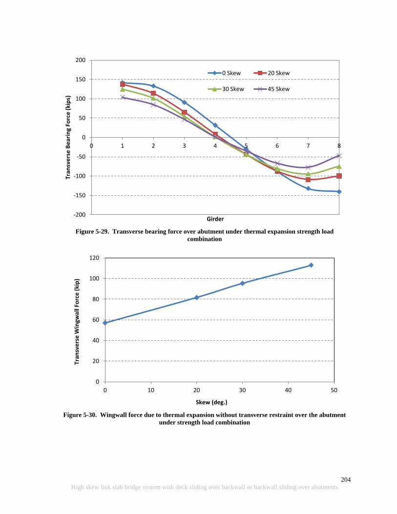
204
High skew link slab bridge system with deck sliding over backwall or backwall sliding over abutments
Figure 5-29. Transverse bearing force over abutment under thermal expansion strength load
combination
Figure 5-30. Wingwall force due to thermal expansion without transverse restraint over the abutment
under strength load combination
-200
-150
-100
-50
0
50
100
150
200
0 1 2 3 4 5 6 7 8
Tran
sve
rse
Be
arin
g Fo
rce
(ki
ps)
Girder
0 Skew 20 Skew
30 Skew 45 Skew
0
20
40
60
80
100
120
0 10 20 30 40 50
Tran
sve
rse
Win
gwal
l Fo
rce
(ki
p)
Skew (deg.)
205
High skew link slab bridge system with deck sliding over backwall or backwall sliding over abutments
5.5 ANALYSIS AND DESIGN PROCEDURES AND DETAILS FOR ABUTMENTS
AND BEARINGS
Detailed analysis of two skew abutment configurations namely deck sliding over backwall
and semi-integral systems was performed for a range of skew angles from 00 to 45
0 and loads
and configurations specified in AASHTO (2010) and the Michigan Bridge Design Manual
(MDOT 2005). The deck sliding over backwall and semi-integral abutment details presented
in Aktan et al. (2008) were used to develop FE models and later modified to accommodate
various bearing configurations and wingwalls. The following is a summary of conclusions
that are derived from the analysis results and information presented in related literature and
design specifications /guidelines.
1. A bridge span with deck sliding over backwall or semi-integral abutments can be
analyzed as simply supported spans to calculate girder end rotations and translation
(expansion/contraction) demands.
2. Skew bridges expand and contract along the diagonal between acute corners. The
movement results in transverse forces at the bearings and other restraint systems. The
restraint force magnitudes become considerably larger if adequate tolerances are not
provided to accommodate the movements due to thermal loads. The situation
requires special consideration when link slabs are implemented over the piers, which
in turn increase the effective length of thermal expansion and contraction. Further,
the direction of bridge movement under expansion and contraction loads needs to be
restricted to the bridge axis. In plane twisting results in large stresses along the edge
of link slab (see Chapter 4). Link slab is also flexible under torsion compared to the
deck-girder integrated system. Hence, controlling bridge alignment is critical when
link slabs are implemented.
3. It is recommended that deck sliding over backwall abutments, is restrain the
transverse movement of the center girder end (for odd number of girders) or two
centermost girder ends (for even number of girders) using concrete keys with rub
plates (shown on Figure 5-8.). Also, larger tolerance is required for the slot in the sole
plate and bearings in order to accommodate the transverse movement of unrestrained
206
High skew link slab bridge system with deck sliding over backwall or backwall sliding over abutments
girder ends. Proposed detail in standard MDOT Bridge Design Guide format is
presented in Appendix F. The required formulations and variables for movement
calculations are presented with the drawings. The rub plate design procedure is based
on the VDOT Bridge Design Manual section 20.04 (2010) with modifications and
presented in Appendix G.
4. Transverse movement of bearings over the semi-integral abutment is facilitated by
increasing the tolerance of the slot at the bearing plate. Transverse restraint for
expansion thermal load is provided by a wingwall at the acute corner. Alignment of
semi-integral abutment bridge deck with backwall offset from the abutment is
managed under contraction thermal loads by placing a concrete key at the center
girder. Calculation of the transverse force on the wingwall is adopted from the
procedure described in VDOT (2010). Proposed detail in standard MDOT Bridge
Design Guide format is presented in Appendix H.
5. It is recommended that an EPS layer is placed behind the backwall of semi-integral
bridges. This will minimize the passive pressure and results in lower transverse
forces at the wingwall. Although the passive pressure coefficient of EPS is in reality
much lower than four (4), a coefficient of four (4) is recommended for conservative
design until additional supporting data is developed (VDOT (2010)). Further, the
equation given in VDOT (2010) section 20-06-6 can be used to calculate EPS layer
thickness (i.e., Eq. 2-2 in Chapter 2 section 2.4.4).
6. It is recommended that the maximum bearing tolerance in transverse direction is
limited to 0.25 in. Further investigations can be carried out analyzing the impact of
the increased fit tolerances of the girder position dowels on the bridge components.
7. Following link slabs are implemented, controlling friction at the approach slab
interfaces is very critical. Increased friction hinders bridge movement restricting
expansion bearing movement over the abutment. This results in stresses greater than
the concrete modulus of rupture under negative thermal loads. Hence, it is vital to
reduce friction at all the contract surfaces at the abutment and approach to facilitate
207
High skew link slab bridge system with deck sliding over backwall or backwall sliding over abutments
movement of the bridge under expansion and contraction thermal loads. To reduce
friction a 0.025 in. thick polyethylene sheet can be placed during construction over
the fill supporting the approach slab.
8. Bridge expansion length, excluding the approach slab, was calculated for width and
skew angle ranges of single span steel and prestressed concrete bridges under the
MDOT jurisdiction. Strip seal joint width of 3 in. available for thermal movement in
the traffic direction and an expansion and contraction thermal load of 115 0F (Figure
5-20 and Figure 5-21) were assumed. Under such limits, expansion length of
concrete bridge superstructure without skew should be limited to 300 ft. When steel
girder bridges without skew are considered, length should be limited to 275 ft. For
skew bridges, length limits are described in the charts shown in Figure 5-20 and
Figure 5-21.

208
High skew link slab bridge system with deck sliding over backwall or backwall sliding over abutments
Intentionally left blank
209
High skew link slab bridge system with deck sliding over backwall or backwall sliding over abutments
6 SUMMARY, CONCLUSIONS, DESIGN RECOMMENDATIONS,
AND IMPLEMENTATION PLAN
6.1 SUMMARY AND CONCLUSIONS
Four tasks were performed in this project. The first task was to review and synthesize
information related to skew/jointless bridge behavior, modeling and analysis of skew bridge
structural system/components, design and detailing of jointless abutments, and performance
of jointless bridges. In this task specific design configurations with records of better
performance were identified. High skew link slab analysis and design guidelines could not
be found in the literature review. Hence, a detailed analysis of a high skew link slab bridge
system was performed; design procedures and details were developed. Literature review was
very useful in identifying abutment configurations and design details with better performance
records. The most functional detail in these configurations were the use of EPS to reduce
passive earth pressure and the use of rub plates to guide the bridge expansion and contraction
under thermal loads. The Virginia DOT bridge design manual provided calculation details of
EPS layer thickness and rub plate design. The manual also provided the passive pressure
coefficient of EPS and a detailed procedure for calculating design forces on wingwall.
Task two was field monitoring of a high skew bridge under truck loads and thermal loads.
This task was for identifying and documenting the performance of sliding bearings and the
behavior of a skew bridge under various loads types. In-depth understanding of skew bridge
behavior was essential for the defining the analyses framework carried out in task three and
four.
Task three was detailed analysis of skew link slabs and calculation of the associated moment
and force envelopes at the link slab section directly over the pier centerline. The analysis
was performed for a specific bridge span length, width, and girder type, and at various angles
of skew from 00 to 45
0. The finite element (FE) models, for these configurations up to 45
0
skew, were developed and analyzed under loads and load combinations described in
AASHTO (2010). Further, the influence of different bearing configurations on the link slab
moment and force resultants are also investigated. Finally, the design recommendations were
developed for the utilization of link slabs in high skew bridges. The design recommendations

210
High skew link slab bridge system with deck sliding over backwall or backwall sliding over abutments
were developed by integrating findings from the literature review, with the FE analysis
results, and AASHTO (2010) requirements on strength and service load combinations. A
detailed example of skew link slab design procedure is presented in Appendix C.
Task four was the detailed analysis of two skew abutment configurations namely deck sliding
over backwall and semi-integral systems. The analysis models were developed for a range of
skew angles from 00 to 45
0 and analyzed under loads and configurations specified in
AASHTO (2010) and the Michigan Bridge Design Manual (MDOT 2005). Deck sliding
over backwall and semi-integral abutment details presented in Aktan et al. (2008) was the
basis of the FE models. These models were modified to incorporate selected bearing
configurations and wingwalls. Based on findings from the FE analysis combined with
findings from the literature, design recommendations for bearings, abutments, and restraint
systems were developed.
6.2 RECOMMENDATIONS
From the literature review on field assessment of skew bridge behavior under static truck
loads and thermal expansion, and simulations by numerous FE models, three design
recommendations were developed. One recommendation is for the high skew link slab
design, and the other two address the transverse restraint systems, bearing details, and the
abutment configuration of deck sliding over backwall and semi-integral abutments in link
slab bridges.
6.2.1 Link Slab Design
Current link slab design procedures do not incorporate skew effects. A design procedure was
developed following a detailed analysis of skew link slabs and the moment and force
envelopes for various boundary and load configurations. Two major findings are (1) moment
developed in a link slab under temperature gradient loads remains constant irrespective of
span and (2) moment developed in a link slab under live load decreases with increased span.
Analysis results verified that the minimum reinforcement amount required in AASHTO
LRFD Section 5.7.3.3.2 is adequate for the majority of skew link slabs with HRRR or RRHR
support configuration. However, additional reinforcement at the bottom layer is needed to
resist large tensile stresses that develop near the boundaries of the debonded region. A
211
High skew link slab bridge system with deck sliding over backwall or backwall sliding over abutments
detailed design example is presented in Appendix C. Proposed link-slab detail in standard
MDOT Bridge Design Guide format is presented in Appendix E. Three saw cuts are
recommended: one at each end of the link slab and one directly over the pier centerline.
6.2.2 Deck Sliding over Backwall
Two changes are proposed to the current MDOT independent backwall detail. The first one is
to incorporate 0.025 in. thick polyethylene sheet underneath the approach slab. The second
one is a transverse restraint system designed with concrete keys and rub plates. The restraint
system is essential to manage the bridge alignment under thermal effects. In conjunction with
these change recommendations, design procedures are presented. Proposed detail in standard
MDOT Bridge Design Guide format is presented in Appendix F. All the required
formulations and variables are presented with the drawings. The rub plate design procedure
was adopted from VDOT Bridge Design Manual section 20.04 (2010) with some
modifications and presented in Appendix G.
Bridge expansion length, which is the distance along the longitudinal axis measured from
abutment to the nearest fixed bearing, is a function of bridge length, width, and skew.
Expansion joint effective movement rating and allowable movement at bearings are the
limiting factors of bridge expansion length when link slabs are implemented. Based on
maximum strip seal joint width of 3 in and expansion and contraction thermal load of 115 0F,
the following maximum expansion length are recommended:
Straight concrete bridge ≤ 300 ft.
450 skew concrete bridge of 100 ft wide ≤ 200 ft.
Straight steel bridge ≤ 275 ft.
450 skew steel bridge of 100 ft wide ≤ 175 ft.
6.2.3 Semi-Integral Abutment
Changes are also proposed to semi-integral abutment details. These changes are necessary for
managing bridge alignment. Details include the use of wingwalls and girder end restrains
such as concrete keys with rub plates. Further, EPS layer is included behind the backwall to
reduce passive pressure acting on the backwall. The EPS layer will help with reducing
transverse forces on wingwalls and girder end restraints. It is also recommended that a 0.025
212
High skew link slab bridge system with deck sliding over backwall or backwall sliding over abutments
in. polyethylene sheet is provided underneath the approach to reduce frictional forces.
Reducing frictional forces is necessary for preventing link slab cracking. Transverse force
calculation on the wingwall is based on the procedure described in VDOT (2010). Proposed
detail in standard MDOT Bridge Design Guide format is presented in Appendix H. The
bridge expansion length limitations presented in section 6.2.2 are also valid when link slabs
are implemented in semi-integral bridges.
6.3 IMPLEMENTATION PLAN
The focus of this work has been the investigation of the behavior and load demands on high
skew link slab and jointless abutment configurations and to develop design modifications to
the current link slab, bearing, wingwall, and other girder end restraint configurations. The
abutment configurations were limited to those commonly used in Michigan, namely deck
sliding over backwall and semi-integral abutments. Also, national and international best
practices on controlling abutment distress in skew bridges were reviewed, and promising
configurations and details were recommended.
Below, the required future work is outlined. Implementation of the following is required
before incorporating the recommendations in MDOT specifications, manuals and guides.
The proposed link-slab details and support configurations should be incorporated as a
pilot implementation project. The implementation project needs to be monitored to
document the behavior and performance in order to evaluate and fine-tune the
proposed analysis and design procedures.
An increase to bearing tolerances is recommended for the slot dimensions of the
alignment pins. This recommendation is for reducing forces developed at the
abutments under thermal expansion and contraction loads. A maximum tolerance
limit of 0.25 in. was recommended after reviewing typical bearing details and
specification requirements. Additional recommendations were also provided for
reducing friction forces on the backwall and approach slab. Again, a pilot
implementation project with monitoring that incorporate the recommended details for
the abutment region is the next step.
213
High skew link slab bridge system with deck sliding over backwall or backwall sliding over abutments
7 REFERENCES
AASHTO (2010). AASHTO LRFD Bridge Design Specifications, Fifth Edition, Washington,
DC, 20001.
AASHTO (2008). AASHTO LRFD Bridge Construction Specifications, Second Edition with
2008 Interims, Washington, DC, 20001.
Aktan, H.M., Attanayake, U., and Ulku, A. E. (2008) Combining Link-Slab, Deck Sliding
over Back-Wall and Revising Bearings, MDOT RC-1514, Report to the Michigan
Department of Transportation, Detroit, MI 48226.
Aktan, H., Koyuncu, Y., Rutyna, J., Ahlborn, T.M., & Kasper, J.M. (2002). Causes and
cures for prestressed concrete I-beam deterioration, Research report RC-1412, Michigan
Department of Transportation, Lansing, Michigan.
Badie, S. S., Tadros, M. K., and Pedersen, K. E. (2001). “Re-examination of I-Girder/Pier
Connection Jointless Bridges.” PCI Journal, Vol. 46, No. 2, pp. 62-74.
Burke, M. P., Jr., (1999). “Cracking of Concrete Decks and Other Problems with Integral-
Type Bridges.” Transportation Research Record 1688, Paper No. 99-0104, Transportation
Research Board, Washington, D.C.
Burke, M. P., Jr. (1994a). “Semi Integral Bridges: Movements and forces.” Transportation
Research Record 1460, Transportation Research Board, Washington, D.C.
Burke, M.P., Jr. (1994b). “Semi-Integral Bridges: A Concept Whose Time Has Come?”
Continuous and Integral Bridges, EAFN Spon, pp. 213-224.
Caner, A. and Zia, P. (1998). “Behavior and Design of Link Slab for Jointless Bridge
Decks.” PCI Journal, May-June 1998, pp. 68-80.
Chandra, V., et al. (1995). Draft Report on Precast Prestressed Concrete Integral Bridges,
State-of-the-Art. Precast/Prestressed Concrete Institute, 113 pp.
214
High skew link slab bridge system with deck sliding over backwall or backwall sliding over abutments
Elragi, A.F. (2011). http://www.softoria.com/institute/geofoam/material.html#36 (Last
accessed May 26, 2011).
FHWA (2011). Rapid embankment construction: Expanded polystyrene (EPS) geofoam.
http://www.fhwa.dot.gov/bridge/abc/eps.cfm (Last accessed May 27, 2011).
Frydenlund, T. E. and Aabøe, R. (2001). “Long term performance and durability of EPS as a
lightweight filling material, EPS Geofoam.” 3rd
International Conference, Salt Lake City.
Gilani, A., and Jansson, D. (2004). Link Slabs for Simply Supported Bridges: Incorporating
Engineered Cementitious Composites. Draft Report No. MDOT SPR-54181, Michigan
Department of Transportation, Lansing, Michigan.
Hambly, E.C. (1991). Bridge Deck Behavior, Second Edition, Van Nostrand Reinhold, 115
5th
Avenue, New York NY 10003.
Hoppe, E. J. (2005). Field Study of Integral Backwall with Elastic Inclusion. Research report
VTRC 05-R28, Virginia Department of Transportation, Richmond, VA.
Hoppe, E. J. and Bagnall, T. M. (2008). Performance of a Skewed Semi-Integral Bridge:
Volume I: Field Monitoring. Research report VTRC 08-R20, Virginia Department of
Transportation, Richmond, VA.
Husain, I. and Bagnariol, D. (1999). Semi-Integral Abutment Bridges, Report BO-99-03,
Ministry of Transportation, Ontario, Canada.
Lutenegger, A. J. and Ciufetti, M. (2009). Full-Scale Pilot Study to Reduce Lateral Stresses
in Retaining Structures Using GeoFoam, Vermont Agency of Transportation, Materials and
Research Section, Montpelier, VT.
Maruri, R., and Petro, S. (2005). “Integral Abutment and Jointless Bridges (IAJB) 2004
Service Summary.” Proceedings of the IAJB 2005, March 16-18 2005, Baltimore, Maryland.
MDOT (2006). Bridge Design Guide. Michigan Department of Transportation, Lansing, MI.

215
High skew link slab bridge system with deck sliding over backwall or backwall sliding over abutments
MDOT (2005). Bridge Design Manual. Michigan Department of Transportation, Lansing,
MI.
MnDOT (2011). MnDOT Standard Plans, Minnesota Department of Transportation, MN.
Moorty, S., and Roeder, C. (1992). “Temperature-Dependent Bridge Movements.” Journal of
Structural Engineering, Vol. 118, No.4, pp. 1090-1105.
Menassa, C., Mabsout, M., Tarhini, K. and Frederick, G. (2007). “Influence of Skew Angle
on Reinforced Concrete Slab Bridges.” Journal of Bridge Engineering, Vol. 12, No. 2, pp.
205-214.
Nakai, H. and Yoo, C.H. (1988). Analysis and design of curved steel bridges, McGraw-Hill,
New York, pp. 575.
Najm, H., Patel, R. and Nassif, H. (2007). “Evaluation of Laminated Circular Elastomeric
Bearings.” Journal of Bridge Engineering, Vol. 12, No. 1, pp. 89-97.
NCDOT (2007). http://www.ncdot.org/doh/PRECONSTRUCT/highway/structur/
springfield/2007/site2/default.html (Accessed: March 2009).
Nicholson, B.A.; Barr, J.M.; Cooke, R.S.; Hickman, R.P.; Jones, C.J.F.P.; and Taylor, H.P.J.,
(1997). Integral Bridges: Report of a Study Tour to North America. Concrete Bridge
Development Group, U.K., 93 pp.
Oesterle, R.G., Tabatabai, H., Lawson, T.J., Refai, T.M., Voltz, J.S., and Scanlon, A. (1999).
Jointless and Integral Abutment Bridges. Summary Report, Final Report to Federal Highway
Administration, Washington D.C.
Parke, G. A. R. and Hewson, N. R. (2008). ICE Manual of Bridge Engineering, 2nd edition,
Thomas Telford, London.
Purvis. R. (2003). Bridge Deck Joint Performance. NCHRP Synthesis 319, Transportation
Research Board, Washington, D.C.

216
High skew link slab bridge system with deck sliding over backwall or backwall sliding over abutments
Roeder, C. W. and Stanton, J. F. (1996). Steel Bridge Bearing Selection and Design Guide,
Highway Structures Design Handbook, Vol. II, Chapter. 4, American Institute of Steel
Construction, Inc., National Steel Bridge Alliance, Chicago, IL.
Romkema, M., Attanayake, U., and Aktan, H. (2010). Incorporating link slabs in high skew
bridges during repair activities - design recommendations, Technical Report: CCE-10-01,
Department of Civil and Construction Engineering, Western Michigan University,
Kalamazoo, Michigan.
Sanford, T. C., and Elgaaly, M. (1993). “Skew Effects on Backfill Pressures at Frame Bridge
Abutments.” Transportation Research Record, 1415, Transportation Research Board,
Washington, D.C., 1–10.
Stark, T. D., Arellano, D., Horvath, J. S. and Leshchinsky, D. (2004). Geofoam Applications
in the Design and Construction of Highway Embankments, NCHRP Web Document 65
(Project 24-11), National Cooperative Highway Research Program, Transportation Research
Board, Washington, DC 20008.
Steinberg, E. and Sargand, S. (2010). Forces on Wingwalls from Thermal Expansion of
Skewed Semi-Integral Bridges, FHWA/OH-2010/16, Ohio Department of Transportation,
Columbus, Ohio.
Steinberg, E., Sargand, H., and Bettinger, C. (2004). “Forces in Wingwalls of Skewed Semi-
Integral Bridges.” Journal of Bridge Engineering, Vol. 9, No. 6, pp.563-571.
Tabatabai, H., Oesterle, R.G., and Lawson, T.J. (2005). Jointless Bridges, Experimental
Research and Field Studies. Volume I, Final Report to FHWA, August 2005.
Tindal, T.T. and Yoo, C.H., (2003). “Thermal Effects on Skewed Steel Highway Bridges and
Bearing Orientation.” Journal of Bridge Engineering, Vol. 8, No. 2, pp.57-65.
Ulku, E., Attanayake, U., and Aktan, H. M. (2009). "Jointless Bridge Deck with Link Slabs:
Design for Durability," Transportation Research Record: Journal of the Transportation
217
High skew link slab bridge system with deck sliding over backwall or backwall sliding over abutments
Research Board, No. 2131, Transportation Research Board of the National Academies,
Washington, D.C., pp. 68–78.
Van Lund, J., and Brecto, B. (1999). “Jointless Bridges and Bridge Deck Joints in
Washington State.” Transportation Research Record, 1688, Transportation Research Board,
Washington, D.C., 116–123.
VDOT (2010). Structure and Bridge Manuals, Virginia Department of Transportation,
Richmond, VA.
Weakley, K. (2005). “VDOT Integral Bridge Design Guidelines.” Proceedings of the IAJB
2005, March 16-18 2005, Baltimore, Maryland.
Yazdani, N., and Green, T., (2000). Effects of Boundary Conditions on Bridge Performance.
WPI# 0510843, March 2000, Tallahassee, FL.


![A STUDY OF FRICTION MODEL PERFORMANCE IN A SKEW ROLLING … · rolling are sliding, normal stress, material properties, lubrication condition, roughness and oxidation [1-3]. Due to](https://img.pdfslide.net/doc/110x75/5ec3b02e45f5de319a7aeb23/a-study-of-friction-model-performance-in-a-skew-rolling-rolling-are-sliding-normal.jpg)