Embed Size (px)
Citation preview
International Journal of Science and Research (IJSR) ISSN (Online): 2319-7064
Index Copernicus Value (2013): 6.14 | Impact Factor (2015): 6.391
Volume 5 Issue 5, May 2016
www.ijsr.net Licensed Under Creative Commons Attribution CC BY
High Speed Digital Protection of EHV Line Using
Travelling Waves
Harpreet Kaur1, Dr. Gursewak Singh Brar
2
1Baba Banda Singh Bahadur Engineering College, Fatehgarh Sahib
2Associate Professor and Head EE, Baba Banda Singh Bahadur Engineering College Fatehgarh Sahib
Abstract: Extra High Voltage (EHV) transmission lines are designed to transfer sizably voluminous amount of potency from one
location to another. The length exposed to the environment is a major reason for occurrence of faults on the lines. A fault on a high
voltage transmission line affects the stability of the overall power system, which sometimes leads to aeonian damage of the equipment.
Relays are developed and installed to bulwark the lines. The transmission line aegis relays, in the industry, are predicated on the
fundamental frequency components of the voltages and currents. These relays need at least one fundamental frequency cycle for
performing the aegis operation. In this paper digital techniques which use travelling waves for auspice of EHV line are proposed.
Validation of the fault bulwark is performed utilizing MATLAB SIMULINK transient simulations by varying fault type and fault
location.
Keywords: Travelling waves, transmission line, MATLAB/SIMULINK, protection systems.
1. Introduction
An electric power system comprises of generation,
transmission and distribution of electric energy. Transmission
lines are habituated to transmit electric power to distant
immensely colossal load centers. The rapid magnification of
electric power systems over the past few decades has resulted
in an astronomically immense increase of the number of lines
in operation and their total length. These lines are exposed to
faults as a result of lightning, short circuits, faulty
equipments, mis-operation, human errors, overload, and
aging. Many electrical faults manifest in mechanical
damages, which must be rehabilitated afore returning the line
to accommodation. The renovation can be expedited if the
fault location is either kenned or can be estimated with a
plausible precision. Faults cause short to long term power
outages for customers and may lead to consequential losses
especially for the manufacturing industry[8,9]. Expeditious
detecting, isolating, locating and rehabilitating of these faults
are critical in maintaining a reliable power system operation.
When a fault occurs on a transmission line, the voltage at the
point of fault suddenly reduces to a low value. This sudden
change engenders a high frequency electromagnetic impulse
called the Travelling wave Theory (TWT). These
peregrinating waves propagate away from the fault in both
directions at speeds proximate to that of light. The paper
reports work on analyzing travelling waves, which may occur
on power transmission lines utilizing Bewley Lattice
Diagram (BLD) [l]. High Speed Fault clearance is an
efficacious method of incrementing power transfer and
amending the transient stability of a potency system[2,3].
2. Travelling wave theory
The transmission line conductors have resistances and
inductances distributed uniformly along the length of the line.
Travelling wave fault location methods are conventionally
more opportune for application to long lines.
Transmission lines cannot be analyzed with lumped
parameters, when the length of the line is considerable
compared to the wavelength of the signal applied to the line.
Power transmission lines, which operate at 50-Hz and are
more than 80-km long, are considered to have distributed
parameters. These lines have the properties of voltage and
current waves that travel on the line with finite speed of
propagation. Travelling wave methods for transmission lines
fault location have been reported since a long time.
Subsequent developments employ high speed digital
recording technology by utilizing the peregrinating wave
transients engendered by the fault. It is well known that when
a fault occurs in overhead transmission lines systems, the
abrupt transmutations in voltage and current at the point of
the fault engender high frequency electromagnetic impulses
called peregrinating waves which propagate along the
transmission line in both directions away from the fault
point.These transients peregrinate along the lines and are
reflected at the line terminals complying with the rules of
Bewley’s Lattice Diagrams [4].
Figure1: Bewley lattice diagram
Paper ID: NOV163391 448
International Journal of Science and Research (IJSR) ISSN (Online): 2319-7064
Index Copernicus Value (2013): 6.14 | Impact Factor (2015): 6.391
Volume 5 Issue 5, May 2016
www.ijsr.net Licensed Under Creative Commons Attribution CC BY
The voltage and current at any point x obey the partial
differential equations:
……………………. (1)
……………….........(2)
where L and C are the inductance and capacitance of the line
per unit length. The resistance is assumed to be negligible.
The solutions of these equations are:
……...…….(3)
……..……..(4)
Where Z= the characteristic impedance of the
transmission is line and is the velocity of
propagation.
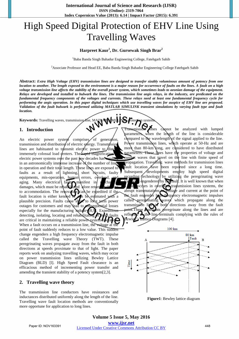
Figure2: Travelling voltage and current waves
Transmission line ends represent a discontinuity or
impedance change where some of the wave’s energy will
reflect back to the perturbance. The remaining energy will
peregrinate to other power system elements or transmission
lines. The fundamental characteristics of fault engendered
travelling wave transients [5] can be summarized as:
a) The wave characteristics change suddenly with the advent
of successive waves at the bus bar. This marks the
occurring of the fault and the peregrinating time for the
peregrination from the fault to bus bar etc;
b) The magnitude of the sudden change depends on the
magnitude of the voltage at the fault instant - e(t). For
later waves, it withal depends on the reflection and
refraction coefficients at the discontinuity and the
attenuation characteristics of peregrinating wave [6]; and
c) The polarity of the sudden change depends on the polarity
of the fault voltage at the fault instant and the
discontinuous characteristics of the wave impedance
3. Simulation model and its results
For evaluating the performance of the proposed algorithm,
the authors adopt MATLAB/ SIMULINK and results
obtained by proposed method are shown below:
Figure 3: Test power system model in MATLAB/SIMULINK
3.1 Case A: Fault Location by Single End Method
In single end fault location method, the high speed digital
relays or fault locators are located at the one end of the
transmission line. The fault distance can be calculated by
formula given below[7]:
………………(5)
D is the distance of fault, Td is the time of fault taken from
the simulation results and v is the velocity of propagation..
Table 1: Single end method results
Fault
Type
Distance of
Fault(km)
Calculated
Distance(km)
Percentage Error
LG 30 27.94 -1.58
LLG 60 62.6 2.02
LL 90 89.04 -0.73
LLL 120 119.10 -0.69
Paper ID: NOV163391 449
International Journal of Science and Research (IJSR) ISSN (Online): 2319-7064
Index Copernicus Value (2013): 6.14 | Impact Factor (2015): 6.391
Volume 5 Issue 5, May 2016
www.ijsr.net Licensed Under Creative Commons Attribution CC BY
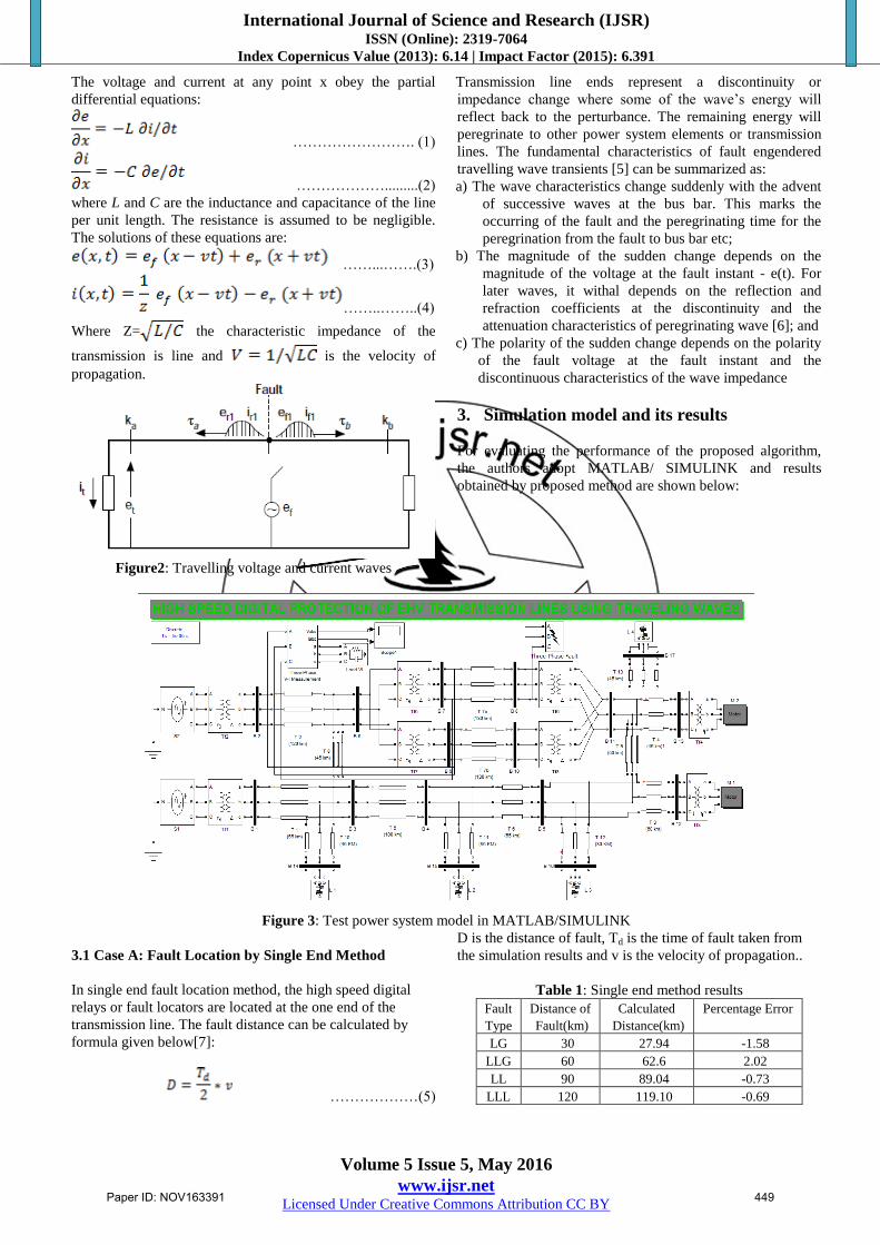
Figure 4: Voltage and current waveform at 30 km(LG FAULT)
Figure 5: Voltage and current waveform at 60 km(LLG FAULT)
Figure 6: Voltage and current waveform at 90 km(LL FAULT)
Paper ID: NOV163391 450
International Journal of Science and Research (IJSR) ISSN (Online): 2319-7064
Index Copernicus Value (2013): 6.14 | Impact Factor (2015): 6.391
Volume 5 Issue 5, May 2016
www.ijsr.net Licensed Under Creative Commons Attribution CC BY
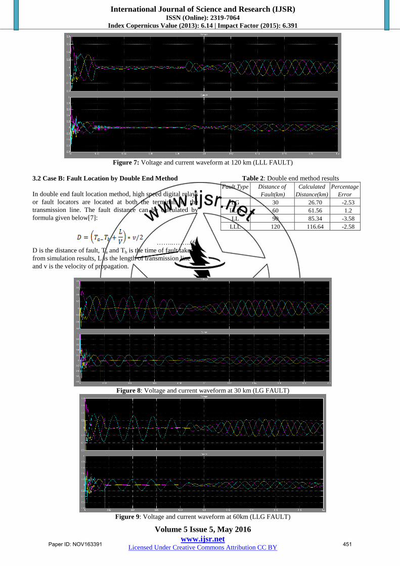
Figure 7: Voltage and current waveform at 120 km (LLL FAULT)
3.2 Case B: Fault Location by Double End Method
In double end fault location method, high speed digital relays
or fault locators are located at both the terminals of the
transmission line. The fault distance can be calculated by
formula given below[7]:
……..……..(6)
D is the distance of fault, Ta and Tb is the time of fault taken
from simulation results, L is the length of transmission line
and v is the velocity of propagation.
Table 2: Double end method results
Fault Type Distance of
Fault(km)
Calculated
Distance(km)
Percentage
Error
LG 30 26.70 -2.53
LLG 60 61.56 1.2
LL 90 85.34 -3.58
LLL 120 116.64 -2.58
Figure 8: Voltage and current waveform at 30 km (LG FAULT)
Figure 9: Voltage and current waveform at 60km (LLG FAULT)
Paper ID: NOV163391 451
International Journal of Science and Research (IJSR) ISSN (Online): 2319-7064
Index Copernicus Value (2013): 6.14 | Impact Factor (2015): 6.391
Volume 5 Issue 5, May 2016
www.ijsr.net Licensed Under Creative Commons Attribution CC BY
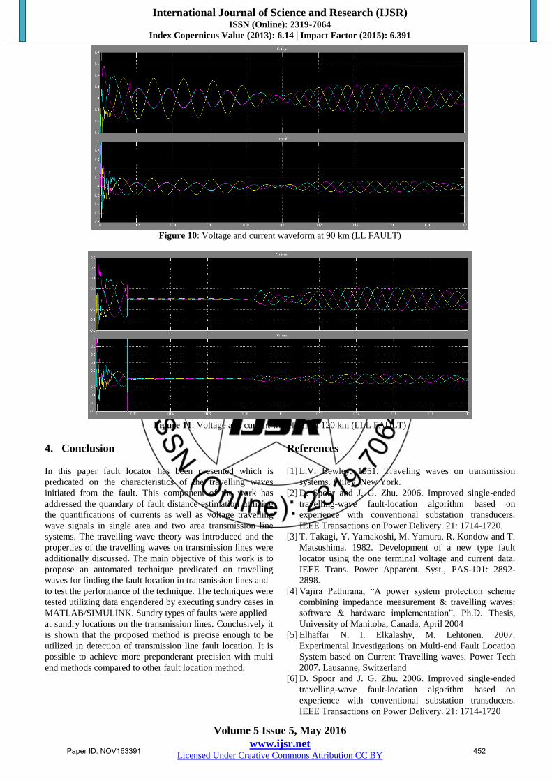
Figure 10: Voltage and current waveform at 90 km (LL FAULT)
Figure 11: Voltage and current waveform at 120 km (LLL FAULT)
4. Conclusion
In this paper fault locator has been presented which is
predicated on the characteristics of the travelling waves
initiated from the fault. This component of the work has
addressed the quandary of fault distance estimation utilizing
the quantifications of currents as well as voltage travelling
wave signals in single area and two area transmission line
systems. The travelling wave theory was introduced and the
properties of the travelling waves on transmission lines were
additionally discussed. The main objective of this work is to
propose an automated technique predicated on travelling
waves for finding the fault location in transmission lines and
to test the performance of the technique. The techniques were
tested utilizing data engendered by executing sundry cases in
MATLAB/SIMULINK. Sundry types of faults were applied
at sundry locations on the transmission lines. Conclusively it
is shown that the proposed method is precise enough to be
utilized in detection of transmission line fault location. It is
possible to achieve more preponderant precision with multi
end methods compared to other fault location method.
References
[1] L.V. Bewley. 1951. Traveling waves on transmission
systems. Wiley, New York.
[2] D. Spoor and J. G. Zhu. 2006. Improved single-ended
travelling-wave fault-location algorithm based on
experience with conventional substation transducers.
IEEE Transactions on Power Delivery. 21: 1714-1720.
[3] T. Takagi, Y. Yamakoshi, M. Yamura, R. Kondow and T.
Matsushima. 1982. Development of a new type fault
locator using the one terminal voltage and current data.
IEEE Trans. Power Apparent. Syst., PAS-101: 2892-
2898.
[4] Vajira Pathirana, “A power system protection scheme
combining impedance measurement & travelling waves:
software & hardware implementation”, Ph.D. Thesis,
University of Manitoba, Canada, April 2004
[5] Elhaffar N. I. Elkalashy, M. Lehtonen. 2007.
Experimental Investigations on Multi-end Fault Location
System based on Current Travelling waves. Power Tech
2007. Lausanne, Switzerland
[6] D. Spoor and J. G. Zhu. 2006. Improved single-ended
travelling-wave fault-location algorithm based on
experience with conventional substation transducers.
IEEE Transactions on Power Delivery. 21: 1714-1720
Paper ID: NOV163391 452
International Journal of Science and Research (IJSR) ISSN (Online): 2319-7064
Index Copernicus Value (2013): 6.14 | Impact Factor (2015): 6.391
Volume 5 Issue 5, May 2016
www.ijsr.net Licensed Under Creative Commons Attribution CC BY
[7] D.C.Idoniboyeobu and P.O.Ohiero High Speed Protection
of Extra high voltage(EHV) Transmission Line using
Digital Travelling Waves International Journal of
Academic Research vol .3. no.5 september 2011.
[8] Vinay K Gupta, Sanjay Mittal , Pawan Kumar Method for
Transmission Line Fault Location International Jouranal
for Technological Research in Engineering vol.2, Issue 9,
May 2015.
[9] Ugwu, Malachy Amechi, Ezechukwu, O.A; Enesi,
David O Fault Location in Extra High Voltage
Transmission Line Case Study: Onitsha –New Haven
Enugu 330 kv Transmission line International Journal of
Emerging Technology and Advanced Engineering vol 5,
Issue9, September 2015.
Author Profile
Harpreet Kaur received B.Tech degree in Electrical
Engg. in 2014 from BBSBEC, Fatehgarh Sahib. She is
currently pursuing her. M. Tech from same institute.
Her research interest includes power system protection
Gursewak Singh Brar received his M.Tech in
Electrical Engineering in 2003 from GNDEC
Ludhiana. He received his Ph.D. in Electrical Engg.
from PTU Jalandhar in Feb. 2010. He is currently
working as associate professor and Head of
Department in Electrical Engg. Deptt. at BBSBEC, Fatehgarh Sahib
(Pb.).His research interest includes Electrical Instrumentation and
Control Engineering using Soft Computing Techniques and Power
System Optimization
Paper ID: NOV163391 453


![High Speed Digital Protection of EHV Line Using Travelling ... · [5] Elhaffar N. I. Elkalashy, M. Lehtonen. 2007. Experimental Investigations on Multi-end Fault Location System based](https://img.pdfslide.net/doc/110x75/5e3e4ec8ba2fe47c6979a712/high-speed-digital-protection-of-ehv-line-using-travelling-5-elhaffar-n-i.jpg)