Embed Size (px)
Citation preview
According to fatigue test resu l t s , fatigue failure of ro tors at s t r e s s levels calculated by this method and obtained by tensometry may occur after 400,000-500,000 loading cycles , in view of this it is necessa ry to con- trol the state of ro to r mater ia l and to d iscard ro tors immediately af ter a fatigue c rack appears.
1.
2.
L I T E R A T U R E C I T E D
V. M. Leshehenko, I. A. Kozlov, and V. P. Gontarovskii, "A method for designing complex-shaped ro to r disks," Probl . Prochn. , No. 5, 3-9 (1972). I. A. Kozlov, V. G. Bazhenov, V. V. Matveev, and V. M. Leshchenko, A Study of the Strength of Machine Par t s by Means of Resistance Tensostra in Gauges [in Russian], Tekhnika, YAev (1967).
H I G H - S P E E D E Q U I P M E N T F O R I M P A C T T E S T I N G
OF M A T E R I A L S
M. A . G o l ' d e r m a n , D. A. K o c h e t o v , A. A. R y b i n , a n d T . A. K h a p i l o v a
UDC 539.4
A number of works have demonstrated the undeniable efficiency of using electrodynamic forces created by the reaction of s t rong pulsed cur ren ts [1-3] in equipment for dynamic tests on mater ia ls and s t ruc tures . Among the methods for real izing this cur rent excitation there is considerable interest in the use of forces result ing f rom the reaction of a pulsed current flowing through an induction coil with a current induced in an active element (striker) located direct ly adjacent to the inductor [2]. Equipment of this type, often called magnetic impulse, is distinguished by its wide speed range (the speed of the s t r iker may be severa l hundredths of a microsecond) , the simplici ty of regulating the speed, and the high reproducibil i ty of the loading p a r a m - e ters .
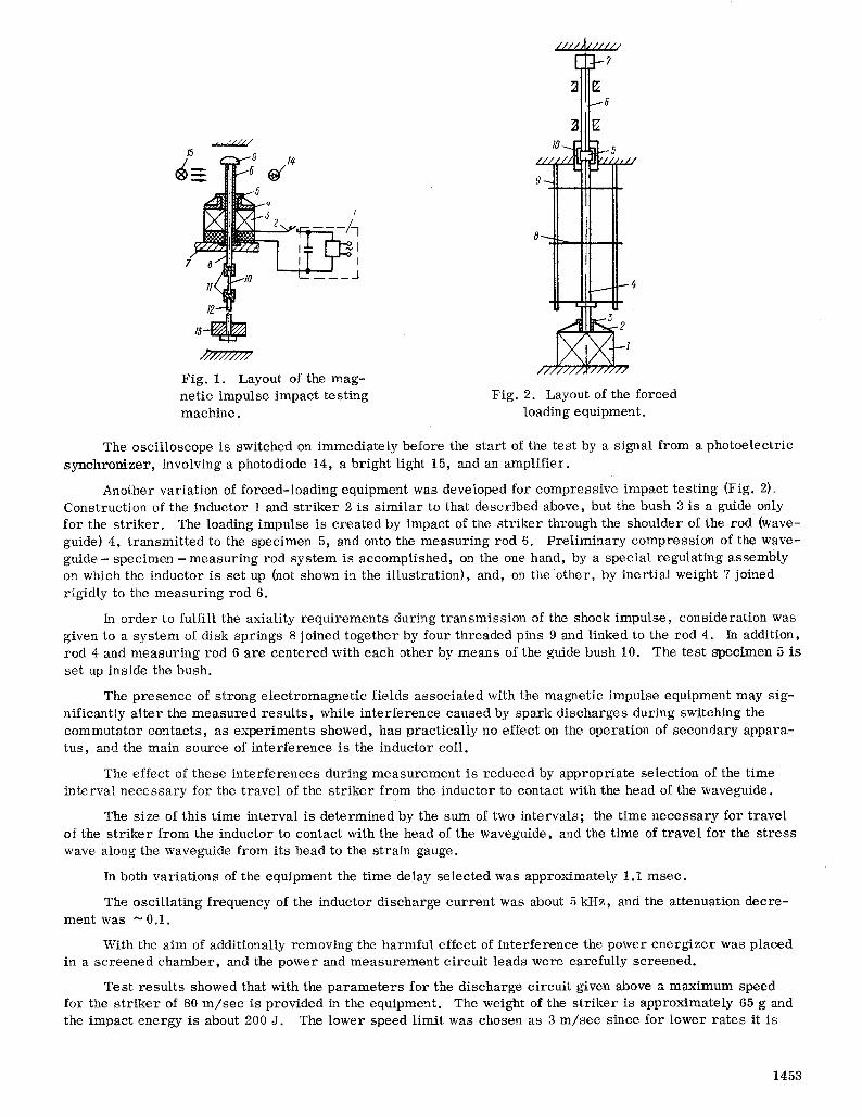
The s t ructural layout of the magnet ic- impulse impact- tes t ing machine developed for testing mater ia ls in tensile impact is i l lustrated in Fig. 1. The pulsed current genera tor (PCG) 1 includes a bat tery of the four - condenser type IMU5-40 with a total capacitance of 560 ttF, voltage 5 kV, and a high-voltage ~upply with a rect i f ier . Closing the discharge circui t is accomplished by a contact- type commutator 2 with a spring re lease .
In o rder to reduce the level of noise associated with the discharge the commutator is located in a sound- proof case.
The inductor 3 is a coil with a spiral copper ribbon winding. The s t r iker 4 is located immediately adja- cent to the inductor, and its body is made of aluminum alloy. The hammer of the s t r iker is made of shock- res is tant mater ia l in the form of a bush 5 with a flange. The bush 5 serves as a guide for the s t r iker and during accelerat ion it moves along the outer surface of sleeve 6 passing through the inductor and f irmly secured to the frame 7. The internal surface of sleeve 6 serves as a guide for rod (waveguide) 8. The shock impulse is received by the head 9 at the end of rod 8, which in the s tar t ing position res t s on the end of sleeve 6. The specimen 10 is secured in the grips 11, one of which is screwed on the free end of the rod, and the other on the end of a Hopkins measur ing rod 12. The measur ing rod with t ensores i s to r s glued close to the grip measures the forces during impact loading. The location of glued t ensores i s to r s and the length of the rod are chosen so that the test is completed before the shock wave reflected f rom the free end of the measur ing rod a r r ives at the t enso t rans fo rmers .
The test is recorded on f o r c e - t i m e coordinates. With this in mind, use is made of an Sl -29 oscilloscope with a memory , which is fed with the signal f rom the t enso t r ans fo rmers .
Graduation of force measurement is ca r r i ed out statically.
Since tensile impact is a h igh-ra te p rocess , in order to keep the measur ing rod immobile during the whole test it is connected with an appropriate inert ial weight 13. The mass is 20 kg for the machine being developed. In this way there is also a p re l iminary interference of the links in the forced-loading sys tem.
Scient i f ic-Research and Construction Institute for Testing Machines, Equipment, and Means of Weight Measurement , Moscow. Transla ted from Problemy Prochnost i , No. 12, pp. 105-106, December , 1979. Original art icle submitted F e b r u a r y 15, 1979.
1452 0039-2316/79/1112-1452507.50 �9 1980 Plenum Publishing Corporat ion
/ / / / ~ / / / / / 2
6
15 u ~ 5
7 II - - - - - -
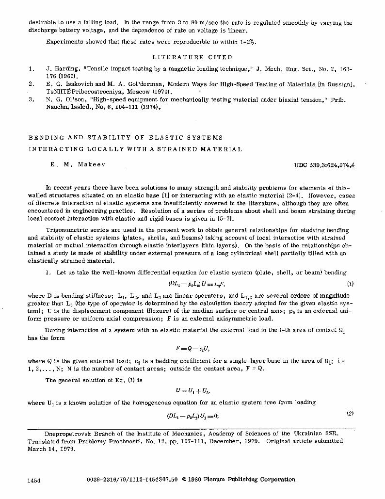
.r / / ~ / Fig. 1. Layout of the mag- netic impulse impact testing Fig. 2. Layout of the forced machIne, loading equipment.
The osci l loscope is switched on immediately before the s tar t of the test by a signal f rom a photoelectr ic synchronizer , involving a photodiode 14, a bright light 15, and an amplifier .
Another variation of forced- loading equipment was developed for compress ive impact test ing (Fig. 2). Construction of the inductor 1 and s t r iker 2 is s imi lar to that descr ibed above, but the bush 3 is a guide only for the s t r iker . The loading impulse is crea ted by impact of the s t r iker through the shoulder of the rod (wave- guide) 4, t ransmit ted to the specimen 5, and onto the measur ing rod 6. Pre l iminary compress ion of the wave- g u i d e - specimen - m e a s u r i n g rod sys tem is accomplished, on the one hand, by a special regulating assembly on which the inductor is set up (not shown in the i l lustration), and, on the other, by inert ial weight 7 joined rigidly to the measur ing rod 6.
In o rder to fulfill the axiality requi rements during t ransmiss ion of the shock impulse, considerat ion was given to a sys tem of disk springs 8 joined together by four threaded pIns 9 and linked to the rod 4. In addition, rod 4 and measur ing rod 6 are centered with each other by means of the guide bush 10. The test specimen 5 is set up inside the bush.
The presence of s t rong e lec t romagnet ic fields associa ted with the magnetic impulse equipment may sig- nificantly a l ter the measured resul t s , while interference caused by spark d ischarges during switching the commuta tor contacts , as exper iments showed, has pract ica l ly no effect on the operation of secondary appara- tus, and the main source of in terference is the inductor coil.
The effect of these in ter ferences during measuremen t is reduced by appropriate selection of the time interval neces sa ry for the t ravel of the s t r iker f rom the inductor to contact with the head of the waveguide.
The size of this time interval is determined by the sum of two intervals ; the time neces sa ry for t ravel of the s t r iker f rom the inductor to contact with the head of the waveguide, and the time of t ravel for the s t ress wave along the waveguide from its head to the strain gauge.
In both variat ions of the equipment the time delay selected was approximately 1.1 msec .
The oscil lat ing frequency of the inductor discharge cur rent was about 5 kHz, and the attenuation dec re - ment was ~ 0.1.
With the aim of additionally removing the harmful effect of interference the power ene rg ize r was placed in a screened chamber , and the power and measuremen t c i rcui t leads were carefully screened.
Tes t resul ts showed that with the p a r a m e t e r s for the discharge circuit given above a maximum speed for the s t r ike r of 80 m / s e c is provided in the equipment. The weight of the s t r iker is approximately 65 g and the impact energy is about 200 J. The lower speed limit was chosen as 3 m / s e c since for lower ra tes it is
1453
des i rab le to use a failing load. In the range f rom 3 to 80 m / s e c the ra te is regulated smoothly by vary ing the d ischarge ba t t e ry vol tage, and the dependence of r a t e on voltage is l inear .
Exper imen t s showed that these r a t e s were reproducible to within 1-2%.
L I T E R A T U R E C I T E D
1. J . Harding, "Tensi le impact tes t ing by a magnet ic loading technique," J . Mech. Eng. Sci. , No. 2, 163- 1 7 6 {1965).
2. E . G . Isakovich and M. A. Go l ' de rman , Modern Ways for High-Speed Test ing of Mater ia l s [in Russian] , TsNIITl~Pr iboros t roen iya , Moscow {1970).
3. N . G . O l ' son , "High-speed equipment for mechanica l ly tes t ing m a t e r i a l under biaxiai tension," Pr ib . Nauchn. I s s l ed . , No. 6 ,104-111 (1974).
B E N D I N G A N D S T A B I L I T Y OY E L A S T I C S Y S T E M S
I N T E R A C T I N G L O C A L L Y W I T H A S T R A I N E D M A T E R I A L
E . M. M a k e e v UDC 539,3:624,074.4
In recent y e a r s there have been solutions to many s t rength and stabi l i ty p rob i ems for e l ements of thin- wailed s t ruc tu r e s s i tuated on an e las t ic base [1] o r in te rac t ing with an e las t ic ma te r i a l [2-4]. However , ca ses of d i sc re te in teract ion of e las t ic s y s t e m s a re insufficiently covered in the l i t e r a tu re , although they a re often encountered in engineer ing p rac t i ce . Resolution of a s e r i e s of p rob l ems about sheli and beam s t ra in ing during local contact in teract ion with e las t ic and r igid ba se s is given in [5-7].
T r igonomet r i c s e r i e s are used in the p r e sen t work to obtain genera l re la t ionships for studying bending and stabil i ty of e las t ic s y s t e m s (plates, she l l s , and beams) taking account of local in teract ion with s t ra ined m a t e r i a l or mutual in teract ion through e las t ic i n t e r l aye r s (thin l ayers ) . On the bas i s of the re la t ionships ob- tained a study is made of s tabi l i ty trader ex te rna l p r e s s u r e of a long cyl indrical shell pa r t i a l ly fi l led with an e las t i ca l ly s t ra ined m a t e r i a l .
1. Let us take the well-known different ia l equation for e las t ic sys t em (plate, shel l , or beam) bending
(DLI - - poL2) U = LaF, (1)
where D is bending s t i f fness ; L1, L2, and L~ are l inea r o p e r a t o r s , and L1, 2 a re seve ra l o r d e r s of magnitude g r e a t e r than L 3 {the type of ope ra to r is de te rmined by the calculation theory adopted for the given e las t ic s y s - t em) ; U is the d isp lacement component {flexure) of the median surface or cent ra l axis ; P0 is an ex te rna l uni- f o rm p r e s s u r e or uniform axial c o m p r e s s i o n ; F is an externa l a x i s y m m e t r i c load.
During interact ion of a s y s t e m with an e las t ic m a t e r i a l the ex te rna l load in the i - th a r e a of contact ft i has the fo rm
F = Q - - c , U ,
where Q is the given ex te rna l load; e i is a bedding coeff icient for a s i ng l e - l aye r base in the a r e a of ~2i; i = 1, 2 , . . . , N; N is the num ber of contact a r e a s ; outside the contact a r e a , F = Q.
The genera l solution of Eq. (1) is
U = U I q--U~,
where U 1 is a known solution of the homogeneous equation for an e las t ic sy s t em f ree f rom loading
(DLI - - poL2) U~ . ~ 0; (2)
Dneprope t rovsk Branch of the Institute of Mechanics , Academy of Sciences of the Ukrainian SSR. Trans la t ed f rom Prob lemy Prochnos t i , No. 12, pp. 107-111, D e c e m b e r , 1979. Original ar t ic le submit ted March 14, 1979.
1454 0039-2316/79/1112-1454507.50 �9 1980 Plenum Publishing Corpora t ion