Embed Size (px)
Citation preview
High-Speed Photography Using a Ruby Optical Maser Tatsuo Yajima, Fujio Shimizu, and Koichi Shimoda
Department of Physics, University of Tokyo; K. Shimoda is also associated with the Microwave Physics Laboratory, Institute of Physical and Chemical Research, Bunkyo-ku, Tokyo, Japan. Received 13 June 1962.
Application of the relaxation oscillation of the ruby optical maser to high-speed photography was first suggested by H. Takuma.1 Instead of the nearly random and frequent occurrence of spikes in the oscillation of an ordinary ruby laser, we obtained fairly regular and widely spaced spikes in our ruby laser with a parallel plate resonator under certain conditions of reflector and
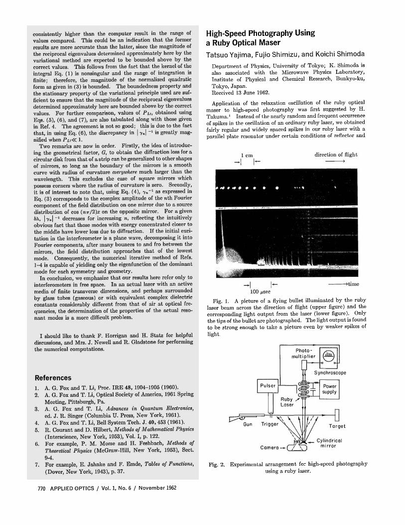
Fig. 1. A picture of a flying bullet illuminated by the ruby laser beam across the direction of flight (upper figure) and the corresponding light output from the laser (lower figure). Only the tips of the bullet are photographed. The light output is found to be strong enough to take a picture even by weaker spikes of light.
Fig. 2. Experimental arrangement for high-speed photography using a ruby laser.
770 APPLIED OPTICS / Vol. 1, No. 6 / November 1962
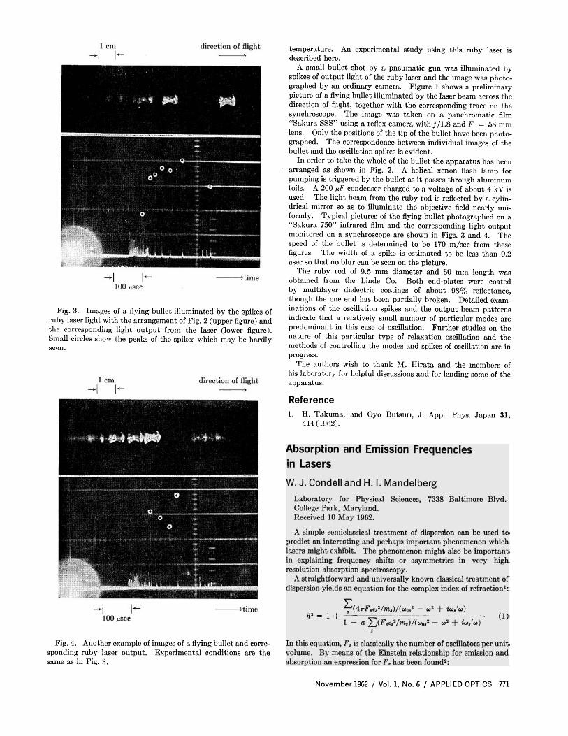
Fig. 3. Images of a flying bullet illuminated by the spikes of ruby laser light with the arrangement of Fig. 2 (upper figure) and the corresponding light output from the laser (lower figure). Small circles show the peaks of the spikes which may be hardly seen.
Fig. 4. Another example of images of a flying bullet and corresponding ruby laser output. Experimental conditions are the same as in Fig. 3.
temperature. An experimental study using this ruby laser is described here.
A small bullet shot by a pneumatic gun was illuminated by spikes of output light of the ruby laser and the image was photographed by an ordinary camera. Figure 1 shows a preliminary picture of a flying bullet illuminated by the laser beam across the direction of flight, together with the corresponding trace on the synchroscope. The image was taken on a panchromatic film "Sakura SSS" using a reflex camera with ƒ/1.8 and F = 58 mm lens. Only the positions of the tip of the bullet have been photographed. The correspondence between individual images of the bullet and the oscillation spikes is evident.
In order to take the whole of the bullet the apparatus has been arranged as shown in Fig. 2. A helical xenon flash lamp for pumping is triggered by the bullet as it passes through aluminum foils. A 200 μF condenser charged to a voltage of about 4 kV is used. The light beam from the ruby rod is reflected by a cylindrical mirror so as to illuminate the objective field nearly uniformly. Typical pictures of the flying bullet photographed on a "Sakura 750" infrared film and the corresponding light output monitored on a synchroscope are shown in Figs. 3 and 4. The speed of the bullet is determined to be 170 m/sec from these figures. The width of a spike is estimated to be less than 0.2 μsec so that no blur can be seen on the picture.
The ruby rod of 9.5 mm diameter and 50 mm length was obtained from the Linde Co. Both end-plates were coated by multilayer dielectric coatings of about 98% reflectance, though the one end has been partially broken. Detailed examinations of the oscillation spikes and the output beam patterns indicate that a relatively small number of particular modes are predominant in this case of oscillation. Further studies on the nature of this particular type of relaxation oscillation and the methods of controlling the modes and spikes of oscillation are in progress.
The authors wish to thank M. Hirata and the members of his laboratory for helpful discussions and for lending some of the apparatus.
Reference 1. H. Takuma, and Oyo Butsuri, J. Appl. Phys. Japan 31 ,
414(1962).
November 1962 / Vol. 1, No. 6 / APPLIED OPTICS 771
![IPD/Bim Thesis Proposal - engr.psu.edu · [IPD/BIM THESIS PROPOSAL] Jason Brognano, Michael Gilroy, Stephen Kijak, David Maser December 6, 2010 KGB Maser KGB Maser| BIM/IPD Thesis](https://img.pdfslide.net/doc/110x75/605d339025f9181d960e06e8/ipdbim-thesis-proposal-engrpsuedu-ipdbim-thesis-proposal-jason-brognano.jpg)


![Ruby on Rails [ Ruby On Rails.ppt ] - [Ruby-Doc.org: Documenting](https://img.pdfslide.net/doc/110x75/554f9e1eb4c9057b298b4732/ruby-on-rails-ruby-on-railsppt-ruby-docorg-documenting-.jpg)


![Ruby on Rails [ Ruby On Rails.ppt ] - [Ruby - [Ruby-Doc.org](https://img.pdfslide.net/doc/110x75/5491e450b479597e6a8b57d5/ruby-on-rails-ruby-on-railsppt-ruby-ruby-docorg-.jpg)