Embed Size (px)
Citation preview

High Spin 7-ray CoincidenceSpectroscopy
with
Large Detector Arraysby
Mats Bergström
1992

COSMIC AND SUBATOMICPHYSICSDISSERTATION ISSN 1101-4202ISRNLUNFD6/NFFK-1005-SE+220PISBN 91-628-0753-6
High Spin 7-ray CoincidenceSpectroscopy
with
Large Detector Arraysby
Mats Bergströmkr
Lund.
November 1992
Akademisk avhandling som för avläggande av filosofie doktorsexamenvid Lunds Universitet matematisk-naturvetenskapliga fakultet offentli-gen kommer att försvaras i föreläsningssal B på Fysiska Institutionenfredagen den 4 december 1992 klockan 1022.

The papers in this thesis are reprinted with he permission of the copy-right holders.
PAPER I,II,IV,V Elsevier Science Publishers B.V. AmsterdamPAPER III Springer Verlag, Heidelberg
The cooperation of the copyright holders is gratefully acknowledged.

o
isi
OrganizationLUND UNIVERSITY
Division of Cosmic and Subatomic PhysicsDepartment of PhysicsSölvegatan 14, S-223 62 Lund
Authors)
Bergström, Mats Henrik
Document nameDOCTORAL DISSERTATION
Date of issue1992-12-04
CODEN:ISRN LUNFD6/NFFK-1005-SE+220P
Sponsoring organization
Thk and subtitle
High Spin gamma-ray Coincidence Spectroscopy with Large Detector Arrays
Abstnct
rIn-beam 7-ray spectroscopy has been used to study rapidly rotating nuclei in the rajfe-
earth region. The experiments were performed using the high-resolution multi detectorarrays ESSA30 and TESSA3 at the Nuclear Structure Facility, Daresbury Laboratoriesin Great Britain and the NORDBALL at the Niels Bohr Tandem Accelerator at Ris0 inDenmark. The studied nuclei were produced using heavy-ion induced fusion-evaporationreactions. New techniques for the analysis of 7-7 correlation spectra were developed.These involves viewing the two-dimensional 7-7 spectrum as well as projection in bothenergy axes, determination of centroids and volumes of peaks and full two-dimensionalGauss fits of an arbitrarily shaped area. The data acquisition system of the NORDBALLmulti detector array is presented. In two of the studied nuclei (167Lu and 163Tm) thestrongly shape driving ir/i9/2[541]|~ is studied. The shift to larger frequency of theneutron AB crossing in these decay sequences is not fully understood. The study of171 Re revealed a second backbend of the [402] | band. The observed bandcrossings areinterpreted using the CSM and three-band mixing calculations. The study of 171-172Wrevealed five new bands and although these nuclei are expected to be stably deformedthe small differences in the deformation showed to be crucial in order to reproduce datawell.
^^ heary-ion reaction!, in-beam 7-ray spectroscopy, high-spin state*, nuclear shape, 7-7correlation», intruder orbitals, cranked (hell model, total routhian surface calculations,data acquisition, multi detector array, two-dimensional spectrum analysis.
Classification system and/or index tenns (if any)
Supplementary bibliographical information
ISSN and key titleISSN 1101-4202 Cosmic and Subatomic Phvsics D i s s e r t a t i o n
Recipient's notes Number of pages
LanguageEngl ish
ISBN91-628-0753-6
Price
Security classification
Distribution by (name and address)^{.g Bergström, Cosmic and Subatomic PhysicsSölvegatan 14 , S-223 62 LUND.
I, the undersigned, being the copyright owner of the abstract of the above-mentioned dissertation, hereby grant to all referencesources permisdon to publish and Aim»min*tr the abstnct of the above-mentioned dissertation.
-tzSnjnsture Date

COSMIC AND SUBATOMICPHYSICSDISSERTATION ISSN 1101-4202ISRNLUNFD6/NFFK-1005-SE+220PISBN 91-628-0753-6
High Spin 7-ray CoincidenceSpectroscopy
with
Large Detector Arraysby
Mats Bergströmkr
Lund.
November 1992
Akademisk avhandling som för avläggande av filosofie doktorsexamenvid Lunds Universitet matematisk-naturvetenskapliga fakultet offentli-gen kommer att försvaras i föreläsningssal B på Fysiska Institutionenfredagen den 4 december 1992 klockan

To my parents
Nils-Erik and Kerstin

Contents
1 Introduction 1
2 The physics of well-deformed rotating nuclei 3
2.1 Deformation 42.1.1 The Nilsson model 6
2.2 The rotating nucleus 82.2.1 The Particle-rotor model 92.2.2 The Cranking model 11
2.3 Pairing 122.4 Comparison with experimental data 13
2.4.1 Bandcrossings 142.5 Formation and decay of the nucleus 16
3 Experimental equipment. 183.1 The germanium detector 183.2 7 ray multiplicity detectors 193.3 ESSA30 193.4 TESSA3 19
3.5 NORDBALL 19
4 Data acquisition, processing and analysis 224.1 Data acquisition 23
4.1.1 The NORDBALL data acquisition system 254.2 Data processing 29
4.2.1 Collected data 294.2.2 Energy calibration and gain matching 294.2.3 Intensity calibration 314.2.4 Histogramming 324.2.5 Background subtraction 334.2.6 Data selection 34
4.3 Data analysis 354.3.1 Analysis of 7-ray coincidence spectra 35
5 Experiments 385.1 171'172W 385.2 167Lu 385.3 163Tm 39

5.4 171Re 39
List of Figures1 Rotational band observed in 171W 32 Prolate and oblate shapes 43 Lund parameterization of quadrupole shapes 54 A Nilsson diagram 75 Body-fixed frame and laboratory frame 96 Extreme angular momentum coupling schemes 107 Routhian and alignment plot of the [642] f+ band in m W . 158 Schematic figure of the decay of a nucleus produced by
a fusion-evaporation reaction 179 Schematic picture of the NORDBALL frame 2010 Major parts of an experiment 2211 Data flow in a general data acquisition system 2312 Data acquisition computer system 2413 The VME part of the NORDBALL data acquisition system 2614 The VAX part of the NORDBALL data acquisition system 2715 Data flow in the VME system of ACQ/ACQ90 2816 Non-linear residual (R(c)) for two germanium detectors. 3017 Typical detector response 3218 D(n) for a 400 x 400 channel area 37
u

Preface
This thesis deals with experiments on rapidly rotating nuclei and thetechniques related to the analysis and data acquisition in these. Theexperiments were performed at the Nuclear Structure Facility at Dares-bury, Great Britain with the ESSA30 and TESSA3 detector arrays andat the Niels Bohr Tandem accelerator Laboratory at Ris0 in Denmarkusing the NORDBALL array. The emphasis is on the data acquisitionand the experimental techniques used for extracting data from the mea-sured spectra. The publications this tLesis is based upon are:
• C.-H. Yu, G.B. Hagemann, J.M. Espino, K. Furuno, J.D. Gar-rett, R. Chapman, D. Clarke, F. Khazaie, J.C. Lisle, J.N. Mo,M. Bergström, L. Carlén, P. Ekström, J. Lyttkens-Lindén andH. Ryde.High Spin Spectroscopic Study of 167Lu.Nucl. Phys. A511 (1990) 157-194.
• M. Bergström and P. Ekström,FourtyTwo - a two-dimensional analysis program for 7^7 coinci-dence matrices.Nucl. Instr. & Methods A103 (1991) 132.
• H.J. Jenssen, G.B. Hagemann, P.O. Tj0m, S. Frauendorf, A. Atag,M. Bergström, A. Bracco, A. Brockstedt, Pt. Carlsson, P. Ek-ström, J.M. Espino, B. Herskind, F. Ingebretsen, J. Jongman,S. Leoni, R.M. Lieder, T. Lönnroth, A. Maj, B. Million, A. Nord-lund, J. Nyberg, M. Piiparinen, H. Ryde, M. Sugavara and A. Vir-tanen.Interaction Strength and Shape Difference for the hg/2 and hn/2configurations in 163Tm.Zeit. Phys. A340 (1991) 351.
• H. Carlsson, M. Bergström, A. Brockstedt, P. Ekström,J. Lyttkens-Lindén, H. Ryde, R.A. Bark, G.B. Hagemann,J.D. Garrett, R. Chapman, D. Clarke, F. Khazaie, J.C. Lisle andJ.N. Mo.Backbending in the 717*13/2 band and proton-neutron interactionsin 171Re.Cosmic and Subatomic Physics Report LUIP 9205, ISRN
111

LUNFD6/(NFFK-7134)1-37(1992), ISSN 0348-9329 and Nud.Phys. Accepted for publication.
• J.M. Espino, J.D. Garrett, G.B. Hagemann, P.O. Tj0m, C-H. Yu, M. Bergström, L. Carlén, P. Ekström, J. Lyttkens-Lindén,H. Ryde, R. Bengtsson, T. Bengtsson, R. Chapman, D. Clarke,F. Khazaie, J.C. Lisle and J.N. Mo.Interpretation of the Rotational Band Structure in 171-172W, TheImportance of Small Deformation Changes.Submitted to Nud. Phys. A (1992)
The results have also been presented at a number of national and in-ternational conferences and workshops, e.g.
• Lund A=180 Workshop, Lund, Sweden 1988.
• Bad Honnef Workshop on Nuclear Structure at High Spins, BadHonnef, Germany, 1989.
• Seminar at McMaster University, Hamilton, Ontario, Canada 1989.
• Gordon Research Conference on Nuclear Chemistry, 1989.
• Copenhagen Workshop on Nuclear Structure in the Era of NewSpectroscopy 1989.
• Svenskt kärnfysikermöte IX, Uppsala, Sweden 1990.
• Ris0 School on New Experimental Techniques in 7-Ray Spec-troscopy 1991.
• EUROGAM Data Analysis Meeting C.S.N.S.M. Orsay, France 1991.
IV

1 IntroductionRotation is maybe the most common type of movement on all scalesin the universe. On large scales, such as the solar system, we knowthat the earth rotates around its own axis as well as around the sunand that the moon rotates around the earth. The sun itself rotatesaround the centre of our galaxy. In the realm of smaller scales, it isknown that molecules rotate and that some atomic nuclei, under certaincircumstances, behave as if they rotated.
The atomic nucleus is small enough to be a quantum-mechanicalobject, and yet, being composed of up to 250 protons and nucleons,it can in many ways be treated with classical methods. Many mud-els describing the nucleus are, in fact a synthesis of a classical andquantum-mechanical approach. The laws of quantum mechanics statethat a spherical object cannot rotate collectively; it must be "deformed"in some sense. On the other hand, our experience in classical mechan-ics says that, if a non-rigid object that is spherical at rest, rotates, therotation will induce a deformation. The earth, having a larger radius atthe equator than at the poles is one example of this and Jupiter, whichrotates twice as fast as the earth and has a radius ten times larger thanthe earth, has an even more pronounced deformation. In the nuclearcase, the rotation also causes an oblate deformation for moderate rota-tional frequencies. At considerably larger rotational frequencies, nucleihas been found that behave as if the rotation had prolonged one axisto be twice as large as the other two.
Although a macroscopic treatment of the rotation of the nucleusmay explain some of the properties qualitatively, the structure "within"the nucleus can only be described by quantum mechanics. One of thefeatures of quantum mechanics is that the nucleons are confined toorbitals, similarly to the case of the planets in the solar system. Alsothe rotation is confined to certain values. This manifests itself whenthe rotation of a nucleus decreases and the corresponding excess energyis emitted as 7-rays with only certain distinct energies, as illustrated infig. 1.
If the rotation of the nucleus were the only factor governing theemitted 7-ray energies in this spectrum, the peaks in fig. 1 would beequidistant, not "contracted" in the middle as is this case. The "con-traction" can be explained by the assumption that at large rotations
1

the nucleus behaves as if it were rigid and at lower rotations as if itwere a liquid drop. This phenomenon is treated in much the same wayas superconductivity. At small rotations the nucleons form pairs in theorbits of the nucleus, moving in an orbit in opposite directions. Whenthe rotation of the nucleus increases, the nucleon moving against the ro-tation tends to change direction and follow the rotation thus leading tothe break-up of the pair. For the study of this this phenomenon the rareearth nuclei are a very good choice since the nucleon pair may occupy"intruder" orbitals that are distinctly different from the neighbouringorbitals and cannot be affected by them.

r**
2 The physics of well-deformed rotatingnuclei
Figure 1: Rotational band observed in 171W.The spectrum is a sum of spectra in coincidence with the 212, 343 and 450keV transitions.
Rotational spectra, as in fig. 1, have been observed in a large numberof nuclei in the rare-earth region since the early 1950's (ref.[l]). Theycorrespond to transitions between states with excitation energies {ER)described (approximately) by:
2J (1)
in which J is the moment of inertia of the object, R is the rotationalmomentum and EQ is the excitation energy corresponding to zero rota-tional momentum.
Rotation is a collective degree of freedom in the nucleus and, as allcollective excitations, it is characterized by a coherent movement of theparticipants. In order for a quantum mechanical object such as thenucleus to rotate collectively it has to be deformed.

2.1 Deformation
(a) Prolate (b) Oblate
Figure 2: Prolate and oblate shapes.
The general expression describing an arbitrary shape in three di-mensions is an expansion in spherical harmonics (yim(i9</?)):
(2)
in which r(tfy) is the length of the vector from the origin to the surfaceof the object in the direction given by i? and <p, r0 describes the size ofthe object and the parameters c/m are the expansion constants.
For the nuclear case it is, however, customary to use a simpler ex-pression and, since the most important deformation type in this case isthe quadrupole, eq.(2) is simplified:
= r0 (1 + C20Y20 + C22 (Y22 + Y2-2)) (3)
If the c22 in this expression vanishes the shape corresponds to a prolateor oblate spheroid depending on the sign of c2o- In most cases c2o andC22 are substituted by 02 and 7 according to
C20 = 02 cos 7 (4a)
(4b)
in which (32 expresses the amount of deformation relative to a sphere and7 the type of deformation. The parameters 02 and 7 span a deformation

CJ
1
= -60
Figure 3: Lund parameterization of quadrupole shapes.
space illustrated in fig. 3. If 7 is 0° or —120° this corresponds to aprolate shape with the symmetry axis orthogonal to or parallel to the1-axis (see eq.(5)), 7 of ±60° corresponds to oblate shapes. The semi-axes, n, may be expressed in terms of ^2 and 7 as:
= r0 1 + cos(T + y i ) ) »=1,2,5 (5)
In the case of spheroidal deformations it is also customary to usethe deformation parameter 6
_ Ar _ 3 [5(6)
where Ar is the difference between the longest and the shortest axis.The deformed potential may then be expressed in terms of 8 and theLegendre polynomial P% with 9 as the angle with respect to the sym-metry axis
V(r,e) = V(T)(l-pP2(coS6)). (7)
For the harmonic oscillator (V(r) = \MU2T2) eq.(7) is identicalto having one oscillator strength in the 3-direction (a>||) and another

in the 1 and 2-directions (w±), as in the first term of eq.(ll). Theincompressibility of nuclear matter is often introduced as a constrainton the two different oscillator strengths and the two most commonparameterizations
= wo(l + 5e) (8a)a,,, = ub( l - fe ) (8b)
'I =,2 _ (9b)
conserve the volume, and the parameters 8 and e both correspond to6 in eq.(7) at small deformations. The original size of the potential isrepresented by wo in eqs.(8,9). It is also customary to use the parameter6otc to describe the amount of deformation for the harmonic oscillator
3 f̂l (10)U!
in which u; = 3(2u>j_ + wj|) is the mean oscillator strength (note that 8oac
= £ if eq.(8) is chosen as parameterization of the deformation).
2.1.1 The Nilsson model
The Nilsson model (ref. [2]) has been extensively used as a simple modelof a deformed nucleus. It uses a modified, deformed harmonic oscillatoras potential V(r), and in spite of being quite different from the actualnuclear potential, it serves a very important role in the understandingof deformed nuclei.
V(r) = \M (ojl(Tl+rl)+Ulrl)^vuf^0(\2-(\2)N)+vlthu;o(l-s) (11)
The second term in eq.(ll) has been added in order to make a crudesimulation of a surface in the potential and has the effect of breakingthe degeneracy within each shell, to favour large I. The parameter (12)JV
is chosen to preserve the average energy for each oscillator shell. Thethird term describes the spin-orbit coupling. The fact that the secondand third terms are small compared to the first makes it reasonable notto introduce deformation in these terms.

Depending on the relative sizes of the second and third componentsin eq.(ll) there are two representations of the states. If the deformationis small (n,Z,j,fl) is appropriate (where n is the principal quantum num-ber, I and j are the orbital angular momentum and the total angularmomentum, respectively, and ft is the component of I along the symme-try axis) and in the limit of large deformation the representation usingthe asymptotic quantum numbers [iVn^Ajft* is known to work well. Inthe latter N is the sum of the harmonic oscillator quantum numbers ineach dimension, nz is the quantum number along the symmetry axis,A and ft are the components of the orbital angular momentum and theangular momentum along the symmetry axis, respectively, and ir is theparity. The eigenstates of eq.(ll) as a function of deformation is shownin fig. 4 (ref.[3]).
7.5
7.0
13
as
6.0
i—muta
^k>a^•Ar* o
r(503»/l]'-I624VI)
/-(615'VU'I8S3J/1]^(622Vd^(73**1]
(671 l/l](512 *1J(510 Vl]1862 Vi]6311/1]752*11
( 5 U l l(50S<Vd633*»]743 T/j]512*1]62**1]
,11631*1)'H671 *jl
*02*>]*0OVl]
;-t761 VI]MMOiU\ MMOi/U
M752*/J]525̂2T /i)
[*0*'/l][51**»J6>
3 » ][*02*ll(523*11( 6 ' l( 6 0 l1521>A]
4761 *i]
-[6*2*1]
0.1 03 0* OS 0£
Figure 4: A Nilsson diagram.Neutron single particle orbits for 82 < N < 126 in a prolate potential. Theorbits are labeled with the asymptotic quantum numbers.

A more realistic potential than eq.(ll) is the Woods-Saxon potential:
V(r) = Vo (12)
where Vo and ro describe the depth and size of the potential and d isthe diffuseness parameter describing the extension of the surface re-gion of the potential. This has the feature of being quite close to thecharge distribution in the nucleus as found from electron scattering ex-periments (ref. [4]), but has quite a few disadvantages as compared tothe harmonic oscillator since it can only be solved numerically. It ishowever known that the states in this model may approximately beassigned to the asymptotic quantum numbers.
2.2 The rotating nucleusFor a rotating system it is customary to denote the body-fixed frame bynumbers and the laboratory frame by letters as in fig. 5 and to expressthe rotating frame in the laboratory system by:
= TsT\ =
n = ry cos ut + rz sin ut
r3 = - r y sin ut + rz cos ut
(13a)(13b)(13c)
In this description the rotating system rotates uniformly around the rx
axis with an angular frequency of u>.If the potential has a body-fixed symmetry axis, customarily as-
signed to axis 3, then no collective rotation is possible about this axis,and the rotational axis, axis 1, is bound to be perpendicular to it. Sincesuch a system is invariant under rotation along axis 3 the componentof the total angular momentum along this, if, is a constant of mo-tion. The total angular momentum is the sum of the rotational angularmomentum and the contribution from the intrinsic states:
I = R + J (14)
and since Ä3 = 0, we immediately find that K — fl.If the potential is also symmetric with respect to a rotation of 180°
along an axis perpendicular to axis 3, this will give rise to the signaturequantum number (a), which for even A nuclei takes the values a — 0and a = 1 and for an odd A nucleus a — ±1/2.
8

Figure 5: Body-fixed frame and laboratory frame.Body-fixed frame (sold lines/numbers) and laboratory-fixed frame (dashedlines/letters). Note that the z and 1 axes are the same and that axis 3 is thedeformation symmetry axis.
2.2.1 The Particle-rotor model
The particle-rotor model is a simple model describing a rotating nu-cleus. In this model a deformed core is responsible for the collective ro-tation to which the angular momentum of valence particles is coupled.The Hamiltonian in this model is divided in two parts, one describingthe intrinsic single-particle states of the valence particles (#intr) andone responsible for the collective rotation:
H = (15)
which together with eq.(14) may be rewritten as (since there is norotation component along axis 3 i.e. I3 = Jj):
H = ( I 2 - 2 I - J
| 1 (I2 -
(16a)
(J\ + 3\))
~ (16b)
in which the last term represents the Coriolis and centrifugal forces,responsible for the coupling between the valence particle and the core(I± — l\ ± il2 and J± = Jx ± iJ2).

There are two extreme cases for which two different coupling schemesare used for an odd valence nucleon. The strong coupling, or deforma-tion aligned (or adiabatic) coupling, in which the motion of the va-lence particles is determined by the orientation of the potential, andthe weak coupling, or rotational aligned coupling, where the valencenucleons move with the rotation. The former occurs mainly at largedeformations and moderate to small rotational frequencies where thenucleon couples to the deformed core, while the latter is preferred atfast rotations in which the Coriolis force plays a large role.
n=K
(a) Deformation alignedcoupling
(b) Rotational aligned cou-pling
Figure 6: Extreme angular momentum coupling schemes.
Deformation-aligned bandsIn the deformation-aligned case the influence of the rotation on theparticle (/+ J_ + J_ J+-term) is assumed to be small and is treated as afirst order perturbation.
Here I will assume values:
I =Sl = K,K + 1,K + 2... (17)
and the perturbation will affect only states with K = 1/2 (due to theselection rules for J+ and «7_) by an amount, fixed for each K = 1/2
10

orbital and given by the decoupling factor:
a = (K = 1/2 | j + | K =
The level energies h thus given by :
-1/2} (18)
Ej,K = ~ - K2 (19)
Rotation-aligned bandsAt large rotational frequencies the I • J term in eq.(16) may no longerbe treated as a perturbation. This is especially true when J is largeand the term may be written IJ:
(1(1 J(J +1) - 21 J) (20)
Since this is identical with eq.(l) the level spacing for odd-A nucleishould be almost the same as for the corresponding "core"-(even-even)nucleus.
2.2.2 The Cranking model
The cranking model (ref. [5]) is used for high spin states in which theCoriolis and centrifugal forces act strongly on the particles, and therotation is treated as a mean field. The single-particle cranking Hamil-tonian has one part describing the intrinsic potential (h°) and one partproportional to the angular frequency (—hujx) that can be derived fromeq.(13):
hu = h°- Hu>jt (21)
This second term in the cranking Hamiltonian breaks the time-reversalsymmetry and K is no longer a constant of motion. The signature(symmetry with respect to a rotation of 180°), however, is still conservedas a good quantum number.
The single-particie energies in the rotating frame are given by:
e'v = etp - hu(jx) (22)
which is called the single-particle Routhian. The expectation valueof the component of the spin along the rotational axis is called the
11

% : J . •
alignment and may be extracted from eq.(22) by:
iv = {jx) = ~ z (23)
The total Routhian and the alignment is simply the sum of the singleparticle Routhians and alignments:
e' = X X (24)
t = 5> (25)V
2.3 PairingThe pairing force is a two-body force that has the effect of lowering theenergy of a state involving pairs of particles in time-reversed orbits. Inspite of being a totally different physical phenomenon from Cooper pairs(ref.[6]) in solid state physics, a similar technique is used for treatingthe pairing correlation in nuclear physics.
The pairing is introduced into the cranked shell model by a termin the Hamiltonian which lowers the energy for pairs of nucleons intime-reversed orbits:
V** = - E Ga\4«3«i (26)
This potential scatters one pair of particles in time-reversed orbits (i, i)into another pair of time-reversed orbits (j,j)- It should be noted thatthis is a two-particle potential, and since such potentials are difficult tohandle, the BCS (ref.[7]) approximation is used. The transformation(ref.[8])
a] = Uia\-Viai (27a)
a\ = «ioJ+«.'«•' (27b)
introduces the quasiparticle creation operators. A quasiparticle is alinear combination of a particle and a hole (ui and v» represent theamplitudes of holes and particles, respectively, u] + vf = 1). The wavefunction of the ground state in the BCS approximation
+ W<5)|0) (28)
12

is the vacuum state of the quasiparticles and is found by minimizing
h'=E ((«.• - A)(4^+4*)) - G £ ( 4 4 ^ ) (29)
in which A is the Fermi energy (or chemical potential) acting as a La-grange multiplier used to keep the expectation value of the number ofparticles equal to N. With the coefficients
\
\ Ik
(30a)
(30b)
where
< = fa - xy Hall terms in eq.(29), quadratic in the quasiparticle operators, vanishand, if higher terms are neglected, the problem is reduced to an inde-pendent-particle problem.
The eigenvalues of eq.(29) with the cranking term added now givethe quasiparticle Routhians:
e;(w) = y/{ei - xy + A* - « i . (32)
in which A is the pair gap which is found in self consistency calculations.
2.4 Comparison with experimental dataIn order to compare experimental data with cranked shell model calcu-lations it is necessary to transform the data into the rotating frame.
Classically the rotational frequency is the derivative of the energywith respect to the angular momentum. In the quantum mechanicalcase the angular momentum is replaced by its expectation value:
w h e r e ( / ) =
In the limit of large I this is very close to the classical formula and, inthe case of I > K, 1(1 + 1) can be replaced by Ix, since fig. 6 suggests:
(34)
13

The form of eq.(33) makes it convenient to define the rotational fre-quency for the energy between two levels and the corresponding Ix as:
h ^ (35a)
(35b)
in which Ia = §(/; — If) and the indexes i and / denote the initial andfinal states, respectively. Note that if I > K and A/ = 2, hua « | E 7
(half the 7-ray transition energy). The transformation of the energiesinto the rotating frame
E' = EX- u>Ix (36)
does not reflect the single particle energies alone but also the rotation.The latter is removed by subtracting the rotational energy of the groundstate configuration for the appropriate even-even nucleus, E'g{u), as aframe of reference. Since this is only valid in a small interval of w, anextrapolation is needed
J ( 3 7 )
in which Jo and J\ are determined from systematics of low-spin mem-bers of the ground-state band in even-even nuclei to fit the Harris for-mula (ref.[9]):
(38)
The same arguments are used to extrapolate Ixg
Ixg{u) = u; Jo + u;3 J i (39)
and the single-particle Routhian (e') and alignment (i) are calculatedfrom
e'(w) = E\u)-E'a{w) (40a)
i{u>) = / ,(«) - JIfl(u;) (40b)
2.4.1 Bandcrossings
A closer look at the spectrum in fig. 1 reveals that the peaks are notequidistant as would be expected for a constant moment of inertia.
14

Plotting the Routhian and the alignment (fig. 7a,b) of the band revealsthat two bands cross at a critical rotational frequency (u>c) and that thenucleus gains (in this case) approximately 6 units of angular momentumat this point.
0-2 03 0.4 OS 0.6fco
(a) Routhian (b) Alignment
Figure 7: Routhian and alignment plot of the [642] §+ band in m W .
The quasiparticles for an even-even nucleus in the ground state alloccupy the states below the Fermi surface, leaving the states above itunoccupied. The effect of the — ujx term in eq.(21) is to lower theenergy of states with high j and low ft by increasing w. At the criticalrotational frequency (uc), the energy associated with the — ujx term,for these highly aligned orbitals, is comparable with the quasiparticleenergies, but of opposite sign, forcing the orbital to approach the Fermisurface and to overcome the pairing gap. At rotational frequencieslarger than u>c it is energetically more favourable for the quasiparticlesto occupy the levels forced down by the — ujx term. The decay patternof such a rotational band will reflect this bandcrossing approximately asshown in fig. 7. If the crossing bands have the same signature and paritythey will interact and interchange identity. Depending on the strengthof this interaction the crossing may be gradual (large interaction) orabrupt (weak interaction), the former case resulting in an "up-bend"in the alignment plot while the latter in some cases will result in a"back-bend".
15

2.5 Formation and decay of the nucleusHigh spin-states of a nucleus are populated by fusion reactions inducedby heavy-ions (in the rare-earth region) or coulomb excitation reactions(in the actinide region). In fusion reactions two nuclei are brought tocollide to form a compound nucleus.
In a reaction like this the energy of the resulting compound nucleusis given by
m E l a b + Q (41)
where E^ is the energy of the beam particle in the laboratory frame andQ is the Q-value for the reaction. The maximum angular momentumof the reaction is reached when the reaction takes place as a "grazing"impact. This distance can be estimated (ref.[10]) by
JV « (1-12(^1 + 4£ e t ) - 0.94(i£2 + iC£.) + 3-0) fm (42)
and gives, together with the Coulomb energy (e2 = 1.44 MeV fm)
Kgr
the maximum angular momentum for the reaction
~ Ec) (44)
where /z = i4teomi4torget/(^öeam + Atargct) is the reduced mass. Theenergy and angular momentum available for the collision is convertedinto internal degrees of freedom. The formation time of the system isin the order of 10~22s.
This compound nucleus is in a very highly excited state and willdecay in order to remove energy and angular momentum. The decaydepends very much on the reaction used, but is in most cases domi-nated by particle emission (n,p,a). Often a reaction is chosen so thatthe wanted final nucleus is reached through neutron evaporation, sincealthough each emitted neutron will carry in the order of 5 to 10 MeVof energy, the angular momentum carried by the neutron will be onlyabout two units. The nucleus emits particles until it is in the vicinityof the yrast line where 7 ray emission starts to compete (after about10-19 s).
16

The first few 7 rays following the particle decay correspond to sta-tistical dipole transitions and have energies from about 1 to 5 MeV,taking the nucleus closer to the yrast line. When in the immediatevicinity of the yrast line the nucleus starts to lose rotational energy byemitting 7 rays through stretched, collective electric quadrupole tran-sitions. These transitions originate from two slightly different typesof states: states very close to the yrast line where the level density issmall, leaving the states mainly unmixed, and states further away fromthe yrast line where the level density is so high that all states (of thesame parity and signature) mix. The latter type of states have a verylarge number of possible transitions to decay by, and may therefore notbe distinguishable from each other by the methods available, but may,instead, form a continuum in the 7 ray spectra measured.
Angular Momentum
Figure 8: Schematic figure of the decay of a nucleus produced by a fu-sion-evaporation reaction.The regions corresponding to the 3,4 and 5 evaporated neutrons are indicatedby the contours. Statistical 7-ray transitions deexciting the nucleus bring thestate further down towards the yrast line (indicated by the arrows). As thestate of the nucleus is close to the yrast line, excess energy and angular mo-mentum is instead lose by stretched E2 transitions. The shaded area indicatesthe origin of the "continuum".
17

v J
3 Experimental equipment.
3.1 The germanium detectorIn this field by far the most common detector used for detecting 7-rayenergies up to 10 MeV are high-purity germanium detectors (HPGe).These are large crystals of pure germanium acting as a diode and givinga current pulse proportional to the amount of energy deposited in thedetector. This current pulse is created when the 7 ray interacts withthe atoms in the detector, creating a number of electron-hole pairscorresponding to the 7-ray energy. There are three types of interactionspossible:The photo-electric interaction, in which the 7 ray is totally absorbedby an atom. The energy deposited in the detector corresponds to the7-ray energy.The Compton scattering, in which the 7 ray is scatted by an electronof an atom. The 7 ray can then either interact a second time inside thedetector or escape. The energy deposited in the detector depends onthe original 7 ray and the scattering angle. The result is a continuousfunction.The pair production, in which an electron-positron pair is created andthe remaining energy is shared among the particles. The 7 ray energymust be larger than twice the electron mass (1022 keV) for this tohappen. One or both of the particles created can escape from thedetector and the energy deposited in the detector will then be equal tothe 7-ray energy minus the energy carried by the particle(s) not caughtin the detector.
In order to detect when some part of the 7-ray energy has escapedfrom the germanium detector, it is customary to surround it by anotherdetector. This detector is used in anti-coincidence with the germaniumdetector, i.e. the signal from the germanium detector is used only ifthere is no signal from the surrounding detector. This suppressiondetector is often composed of several smaller detectors of either Nal orBGO (BiAGe30i2) scintillators.
For selection purposes (see sect 4.2.6), not only the 7 ray energyfrom the germanium detector is used, but also the time when the ger-manium detector registered the 7 ray. This time is measured relative tothe first 7 ray to be registered, using either a multiplicity detector or a
18

germanium detector. In the latter situation, it is common to choose asreference a germanium detector for which the corresponding Comptonshield has been triggered and is thus not in the event.
3.2 7 ray multiplicity detectorsThis type of detector is designed to detect the number of 7 rays and thetotal energy emitted as 7 rays from the nucleus. The detector is oftencomposed of a large (50 for TESSA3 and 60 for NORDBALL) number ofBGO or BaF2 scintillators. It is normally the sum of the 7-ray energieswhich is used, no; the individual energies. This is called the sum energyand is used, together with the number of 7 rays detected by the detector(the 7 ray multiplicity), for data selection.
3.3 ESSA30
The ESSA30 detector array, at the Nuclear Structure Facility (NSF)at Daresbury, Great Britain, was an assembly of thirty Compton-sup-pressed, germanium detectors. The frame holding the detectors hadthe shape of a truncated icosahedron. This shape is composed of 12pentagons and 20 hexagons all but two of which used for a detector.The angles made by the line from the target, to the detectors, withrespect to the beam line, were 37°, 63°, 79°, 101°, 117°and 143°.
3.4 TESSA3
The TESSA3 detector array was also located at the NSF, Daresbury,and included 12 Compton-suppressed germanium detectors and an in-ner ball of 50 BGO scintillators. The inner ball was used to extractthe number of 7 rays and the sum energy of these for each event (seesect 4.2.6). The germanium detectors were placed in two rings at ±19°above/below the beam line. The position of the six detectors in eachring was at ±60°, ±90° and ±120° with respect to the centre of thering.
3.5 NORDBALL
NORDBALL is an array of twenty Compton-suppressed germanium de-tectors. A number of other detector types can be inserted in the setup.
19

As in the case of ESSA30, the germanium detectors are held by a framein the shape of a truncated icosahedron, but here only the hexagonsare used for the germanium detectors. The diameter of the frame is 66cm.
Figure 9: Schematic picture of the NORDBALL frame.
The beam-line goes through the center of the ball and through thecenter of two of the pentagons. The angles of the germanium detectorsrelative to the beam line are 37°,79o,101° and 143°.
The inner ball is composed of 60 BaFj crystals each 95 mm deep,and with an inner and outer diameter of 300 mm and 100 mm, respec-tively. The total solid angle covered by the detector is 96%. For eachgermanium detector there is a corresponding hole allowing the 7-raysto reach the germanium detectors without penetrating the inner ball.There is also one hole in the ball for the beam tube.
Also an X-ray detector available to cover the low-eneregy part of thespectrum. This is a planar germanium detector which can be insertedin one of the hexagons instead of a normal 7 ray germanium detector.
In the forward half of the frame it is possible to replace half of theinner ball and the germanium detectors by neutron detectors (ref.[ll]).
Hystrix (ref. [12]) is a charged particle detector which can be insertedinside NORDBALL instead of the inner ball. The device is capable ofselecting charged particles (p and a). The solid angle of the detector isabout 94%.
The silicon ball (ref.[13]) is another small detector for detectingcharged particles. The Si-Ball fits inside the inner ball and has a solidangle of about 90%.
The countries involved in the collaboration are Denmark, Finland,Norway, Sweden, Holland, Italy, Germany and Japan, with the Nordiccountries carrying the main responsibility.
20

4 Data acquisition, processing and analy-sis
DataAcquisition
DataProcessing
Analysis
Interpretation
The experimental part of nuclear high-spinspectroacopy (and most other experimentaldisciplines) may be divided into data acqui-sition, data processing, analysis and finallyinterpretation. The boundaries between theseare usually very diffuse, albeit distinguish-able:Data acquisition may be defined as the ac-tual measurement and collection of the data(and storage for later use), data "processingis the restructuring of the data without ana-lysing them,e.g. calibrating, gain-matching,sorting, ordering, histogramming and copy-ing. Often parts of the data processing areperformed during the acquisition. Analysis F i g u r e 1Q. M a j o r p a r t s of
is the extraction of physical quantities and a n exoe rjmentrelations from the data set and finally, in theinterpretation these quantities are compared with theoretical results.
The data acquisition may in turn be divided into four physical parts,the detectors, the electronics, the computers and storage. The detectorsand electronics are of course physically very close as well as are the elec-tronics and computers. Furthermore, an additional part is needed forcontrolling and maintaining the acquisition system and for monitoringthe quality of the collected data.
Contemporary experiments in high-spin physics have moved in adirection where computers play an increasingly important role. Withthe high collection rates of events (in the order of 5000 to 30000 persecond), and with each event becoming increasingly more complex, fastcomputers as well as efficient and robust programs for these computersare demanded. As computer systems have grown to involve severalindividual computers, sometimes working in parallel, the robustnessof the system, though increasingly more important is more difficult toattain and to maintain.
21

4.1 Data acquisition
Terminal • Control 1 ^ ^ - Interface 4 Interface
(Detector)-•Interface •*>( EleC' , Tape Terminal
Interface » iMonitorl •*+• Display
Terminal
Figure 11: Data flow in a general data acquisition system.The collected data from the detector are passed on to the electronics throughan interface and further into the computer (ACQ) and finally to a mass storagemedium (Tape). A portion of the data is forked off a monitoring module toprovide an on-line quality check of the collected data. Control of the system isprovided through a control program which sends commands to the acquisitioncomputer system which in turn can initiate actions by the user (change oftapes etc.) by sending a message to an appropriate output device.
The purpose of most data acquisition systems is to collect data fromdetectors, in most cases to do rudimentary processing and to store thedata on some sort of mass storage medium (most often tapes). A veryimportant task of the acquisition system is also to provide the user withnecessary control over the system and to monitor the collected data.A very simple model of this is shown in fig. 11 which schematicallydescribes the flow of collected data and data (commands) entered bythe user.
The control of a data acquisition system is one of the big, and clas-sical problems in such an acquisition system. It always forces some partin the acquisition system to scan multiple locations for possible inputdata (in fig. 11 the ACQ module has two input locations, one for dataand one for control commands from the user), hence increasing andcomplicating considerably the states in which the acquisition systemcan be.
22

Terminal -
Control
Acquisition JL»'*'— • (Reader J Tape
Monitoring Interface » | Monitor) — • Display
•Jk. _Terminal
Figure 12: Data acquisition computer systemThe collected data flow enters the system in the reader module and end inan output module, storing it on tape, possibly via a number of preprocessorunits (the intermediate buffers are not shown). The command flow (dottedlines) initiated by the user is managed through a control module which decidesto what part of the system a command should be passed. Replies to thecommands given are sent back to the controlling program through a buffer,while messages from the system to the user are handled separately.
Figure 12 (ignoring detectors and external electronics) can serve asa generic model for a data acquisition system. This consists of fourmajor parts: control, information, the actual acquisition system and amonitoring facility (the latter usually being totally unaware of the restof the data acquisition as such).
The control part has two components, one entirely initiated by theuser (for commands such as "start", "stop" etc) and one initiated bythe system. The latter is used to inform the user of demands for main-tenance (tape changes) and general messages. The control part is notonly used for issuing commands to the system but may also be used tosend data, such as gain matching coefficients, to some of the modules.
As mentioned earlier, modules having multiple input buffers (suchas the "Reader", "Preprocessor" and "Output" modules in fig. 12) are
23

a complicating factor. Great care has to be taken in which order thebuffers are scanned for possible input data as well as how often. Itis of course possible for two (or more) modules to put data into thesame buffer, thus eliminating the dual input problem. This, however,demands that the recipient recognises different types of buffers, whichis also a complication.
4.1.1 The NORDBALL data acquisition system
The data acquisition system of NORDBALL has existed in four versionsof which the second (ACQ90) is built on the first (ACQ), the third(ACQ91) contains major changes in almost every respect and the fourth(ACQ92) is a further development of the third. The first version wasdeveloped over the period 1986 to 1990, the second version 1989-1990,the third was started in 1991 and the latest version, though not fullyfinished at the time of writing, has been run successfully.
The main hardware modules in the first three versions are: the elec-tronics, a VME micro-computer system, a VAX 8650 connected to alarge number of terminals, graphical displays and tape stations. In thelatest version a PC has been added for controlling the VME system.The VME micro-computer system is used as the actual data acquisitioncomputer and is in all four versions programmed in MODULA-2, ex-cept for a small portion for which assembler language was used. A smallkernel and message system for the VME computers, written mainly inMODULA-2, was used for task switching and inter-task communica-tion. The programs running in the VAX/VMS computer are written inVAX-FORTRAN and the VAX/VMS-DCL language.
The VME micro-computer system is built up of a number of MC133modules each having a MC-68010 micro-processor and 500 kbyte ram,as well as another 4 Mbyte ram accessible by all of the MC133 modulesin the crate. For the ACQ and ACQ90 versions seven CPUs running inparallel were used while ACQ91/ACQ92 uses only four.
24

ACQ90The main purpose of the development of ACQ90 from the former ver-sion ACQ was to: i) make the system more transparent and easy tomaintain, ii) remove common bugs as well as obvious errors in design,Hi) enable the VAX to handle any number of VME acquisition systemssimultaneously and iv) prepare some parts of the system to ailow fur-ther development into what later became ACQ91. The third of theseitems was found to be a very good investment as the system develop-ment could be performed on a reduced, "dummy" system while the realacquisition system could be used for live experiments.
•••SerialLink
Figure 13: The VME part of the NORDBALL data acquisition systemThe collected data is read from the interface with the electronics of the "ACQ"module and passed on to the VAX by the "DR11W" module. The lattermanages a high speed DMA interface between the VME system and the VAXcomputer. The VME system communicates with the VAX through an ordinaryfull duplex serial line serviced by one module for receiving and one for sendingdata (commands). The "CAMAC-Server" is a module for read/write accessto the CAMAC crate used by the acquisition system.
Since the computer part of the acquisition system for NORDBALLis built up of two different types of computers, the simple model offig. 12 is somewhat more complicated in detail but remains valid. Thetwo parts of the NORDBALL acquisition computer system are shown in
25

fig. 13 and fig. 14.
SerialLink"«MReceivel • Buffer • • * • I " I • • • • LogFile
Figure 14: The VAX part of the NORDBALL data acquisition systemThe "CRTL&Save" module in the VAX is a combined program for collectingand saving data on tape, for performing preprocessing as well as control ofthe acquisition system. Communication of commands and messages betweenthe VME system and the modules in the VAX is performed by the "Receive"and "Send" modules. The "ErrRec." module collects any error messages forlater investigation. The on-line monitoring of collected data corresponds tothe "SAP" module.
In the VAX the part of the ACQ system looks somewhat differ-ent from the generic picture given. The collected data are read fromthe DR11W DMA interface from the VME system by a combinedController/Tape-saver/Preprocessor program. This program is used forthe three tasks of controlling the ACQ system, saving received data ontape and shipping a portion of the received data to a buffer readableby a separate spectrum analysis program (SAP).
In fig. 15 the data flow in the VME system of the ACQ and ACQ90is shown. Data are read from various types of electronics by dedicatedtasks each running in a separate CPU and put into different buffers.These buffers are read by a merger task, also in a dedicated CPU, whichcombines the different types of data into events which are put into thenext buffer. The merged data are read by an output task which candirect the data to a varying number of output servers, viz "DR11W"(as in the figure), "Serial-Link" or "NULL" (bit bucket). All of this
26

Buffer D R U W
Figure 15: Data flow in the VME system of ACQ/ACQ90Data from CAM AC, NIM and ECL electronics are read by the correspondingreader and placed in different buffers. The Merger merges the different types ofdata together into events before it is shipped to the VAX through the DR11W.
is supervised by a "Commander" task (also in a dedicated CPU, notshown in the figure) which triggers the readers to start reading a newevent, synchronizes the switching of buffers and handles the signallingto the electronics. For efficiency the reader CPU reading CAMACdata runs a very specialized program designed by the user in a pseudolanguage, compiled in the VAX and loaded into the CPU at boot time.
ACQ91 and ACQ92These versions of the NoRDBALL data acquisition system were designedto increase the rate of collection of data to meet the demand of savingthe energies and times registered by the single detectors in the innerball, as well as the demand of higher acquisition rates. To achievethis the readout of data from the various types of electronic devices isperformed by hardware and shipped to one reader in the VME system,i.e. the event builder is moved outside the VME system. As a resultthe different types of data in an event are no longer separated withinthe VME system, as only one reader CPU is used, making the mergertask obsolete, but in order to keep the system compatible with the oldACQ90 there is still a dummy merger task.
While ACQ91 still used the same configuration within the VAXcomputer, the ACQ92 uses a PC for the control of the VME system.As a result the "CTRL&Save" module in the VAX computer was sim-plified into a combined preprocessor/tape-saver. The control of the
27

VME system from a PC has simplified and speeded up the startup ofthe VMS system considerably.
4.2 Data processing
Data processing is a very important part of contemporary 7-ray spec-troscopy and over the past years experiments have been performedwhich have producced more than 100 Gbyte of collected data. Thisamount of data dwarfs that produced by earlier experiments and causesa whole set of new problem in its processing.
4.2.1 Collected data
The data collected in these types of experiments naturally depend onthe experimental detector set-up. In all cases the data are organizedin events. Each event corresponds to data measured within a periodof time, small enough to ensure that the data originate from the samenucleus. Each event normally contains a number (> 2) of 7-ray energiesand an identification of the corresponding germanium detector. In mostcases each of these are also accompanied by a number corresponding tothe relative time at which the germanium detector registered the 7 ray.
For many detector set-ups there is also a multiplicity detector (c.f.the inner ball for the NORDBALL). The number of 7-rays detected bythis unit is about 5 to 8 (depending on the reaction and the detectordesign). Usually, the single 7-ray energies are not used. Instead thesum of the energies and the number of 7-rays are used. These twonumbers are often referred to as sum-energy and multiplicity.
4.2.2 Energy calibration and gain matching
In multi-detector systems such as NORDBALL, ESSA-30, TESSA-3, andEUROGAM, the energy calibration and gain matching are very closelyrelated and constitute one of the most delicate steps on the way to ananalyzable data set.
Gain matching can be denned as the process of forcing each indi-' vidual detector to line up in comparison to all the others, while energyj calibration is the process of determining the correct function connect-\ ing channel number and energy, either for the case of each individual' detector or for the sum of all detectors. The two processes are closely
28

related but there may be small differences in the results depending onwhich of the two is optimised.
0.20-
^ 0.00-
~ -0.20-"2 ~'S -0.40-ot _
-0.60-
n
/
1'I
500 1000Energy (keV)
1500
Figure 16: Non-linear residual (B.(c)) for two germanium detectors.Two detectors in the NORDBALL set-up. As can be seen, one of the detectorscan be represented well by a second order polynomial, while the other oneneeds a more complicated formula to be parametrized. The behaviour of thesecond detector can be explained by the non-linearity of the ADC.
The correspondence between the value registered by each germa-nium detector and the actual energy deposited in the detector is afunction depending not only on the detector but also very much onthe electronic devices involved (amplifiers, ADCs etc.). This functionmay to an acceptable approximation be represented by a simple lin-ear expression if only a single detector is used. Contemporary detectorsystems, however, are built up of 20 or more individual detectors and,when adding spectra from different detectors together, a linear expres-sion may not be sufficient.
E = A + Be + R{c) (45)
Although the non-linear part of the function (fig. 16) is small, it containsfactors of very high order. An efficient way to correct for this is todescribe the non-linearity by a look-up table as in eq.(45) (in whichA and B are the coefficients of the linear function, c is the channelnumber from the ADC and R(c) the look-up table). This expression
29

is general, is rapidly computed and, since the look-up table varies veryslowly with c, it can be considered as a constant feature of the detectorduring an experiment, i.e. even if the detector changes its dispersiononly the parameters A and B need to be changed.
If a spectrum is the result of a sum of a large number of singledetectors, the width of the peaks in this spectrum will be a functionnot only of the widths of the peaks in each single detector but also of thedeviation of each peak position in each detector from the mean positionof the peak in the summed spectrum. The total number of counts ina peak of the summed spectrum, however, is simply the sum of thenumber of counts in each detector regardless of the gain matching. Thismeans that not only will a poor gain matching result in wider peaks,reducing the resolution, but the height of the peaks will also becomesmaller than optimal. And since only peaks with heights of the orderof the local background are detectable, a good gain matching is crucialto the detection of weak peaks. In higher dimensions of spectra thiseffect plays an even greater role.
4.2.3 Intensity calibration
For germanium detectors the probability for a 7-ray to deposit all of itsenergy within the detector varies strongly with the energy of the 7-ray,as can be seen in fig. 17.
Unfortunately the 7 ray energy is not the only parameter affectingthe response of the Ge detector. Often the coincidence criterium (thetime window) plays an important role, especially in the low energy re-gion. This is due to the fact that the cross section for the photo-electricinteraction with the detector is higher for low energy 7 rays than athigher energies. This in turn implies that low energy 7 rays will inter-act with the detector closer to the entrance surface than 7 rays of higherenergy, and the time the detector spends collecting the correspondingcharge released is longer. Thus the time window determining a coinci-dence can affect the detector response. Also the count rate affects theresponse. If the calibration and experimental data are collected withdifferent types of coincidence criteria and count rates, it may becomevery difficult to determine the detector response.
30

1000
Energy (keV)
1500 2000
Figure 17: Typical detector response.Relative efficiency of the NORDBALL detector (i.e. sum of all individual ger-manium detectors). The efficiency calibration was performed using an 152Eusource and is extrapolated below 121.8 keV. Note the logarithmic scale inarbitrary units of the y-axis.
4.2.4 Histogramming
The process of creating the analysable spectra (one-, two- and perhapsthree-dimensional) is not always a simple, straightforward task. Theprinciple is quite simple: for each event tLe corresponding element inthe spectrum is updated (the events are in most cases kept on tapes).The size of the spectrum, however, in two- (and even more so in three-)dimensions is large. A common size of a two-dimensional spectrum is4fc x 4k elements, yielding 16M elements (Ik and \M correspondingto 1024 and 1048576, respectively), each element corresponding to atleast two bytes. Though it is not unusual for computers today, to have32 Mbytes of internal memory, it is not always possible for a singleuser to employ this amount of memory effectively. The updating of atwo-dimensional matrix follows two techniques for reducing the amountof memory needed.
The first method divides the two-dimensional spectrum into a num-ber of sections (commonly 2 to 8), each updated individually. Whenthe event tape is read and an event falls into the current section of thespectrum it is updated immediately. The number of sections is defined
31

r
by how much computer memory the user can claim for this task. Thedisadvantage of this method is that the event tapes have to be read sev-eral times, resulting in rather lengthy sessions, and since the amountof data produced by experiments has grown very rapidly, this methodis not often used nowadays.
The second method is designed only to read the event tapes oncebut also to keep the amount of memory used to a moderate scale. Thismethod also divides the spectrum into a number of sections (8 to 64),each of which is associated with an intermediate file to which the eventsare written sequentially in a compact format. Whenever such a file con-tains more than a certain number of events (depending on the amountof disk space available) the corresponding section of the spectrum isread, updated and written back. This method has proved to be quiteefficient and the time for processing one event tape is typicallv slightlylonger than the time needed to read the tape.
4.2.5 Background subtraction
Pragmatically, the background in a 7-coincidence spectrum can be de-fined as that everything that is not a full-energy peak, correspondingto the decay of a discrete level, in the nucleus (but not in the quasicontinuum). This background is composed of several distinct parts, ofwhich the most important are:Compton-related coincidences. At least one of the 7-rays is related tothe decay of a discrete level in a nucleus and has undergone Comptonscattering in the Ge detector. In two dimensions there are two typesof this scattering, viz. Compton-Compton scattered events, for whichboth of the 7 rays are Compton scattered, which contribute to a smoothbackgrund surface, and Comption-photo peak events for which one ofthe two 7 rays is Compton scattered, the other totally absorbed in thedetector. The latter contributes to a ridge (stripe) on the low-energyside of each peak.Random coincidences. These are truly random and carry no informa-tion.Coincidences related to statistical *y-rays. At least one of the 7-rayscorresponds to a statistical (E2) transition.Coincidences related to neutrons. These are neutron-induced 7-raysfrom the material in the detectors etc.
32
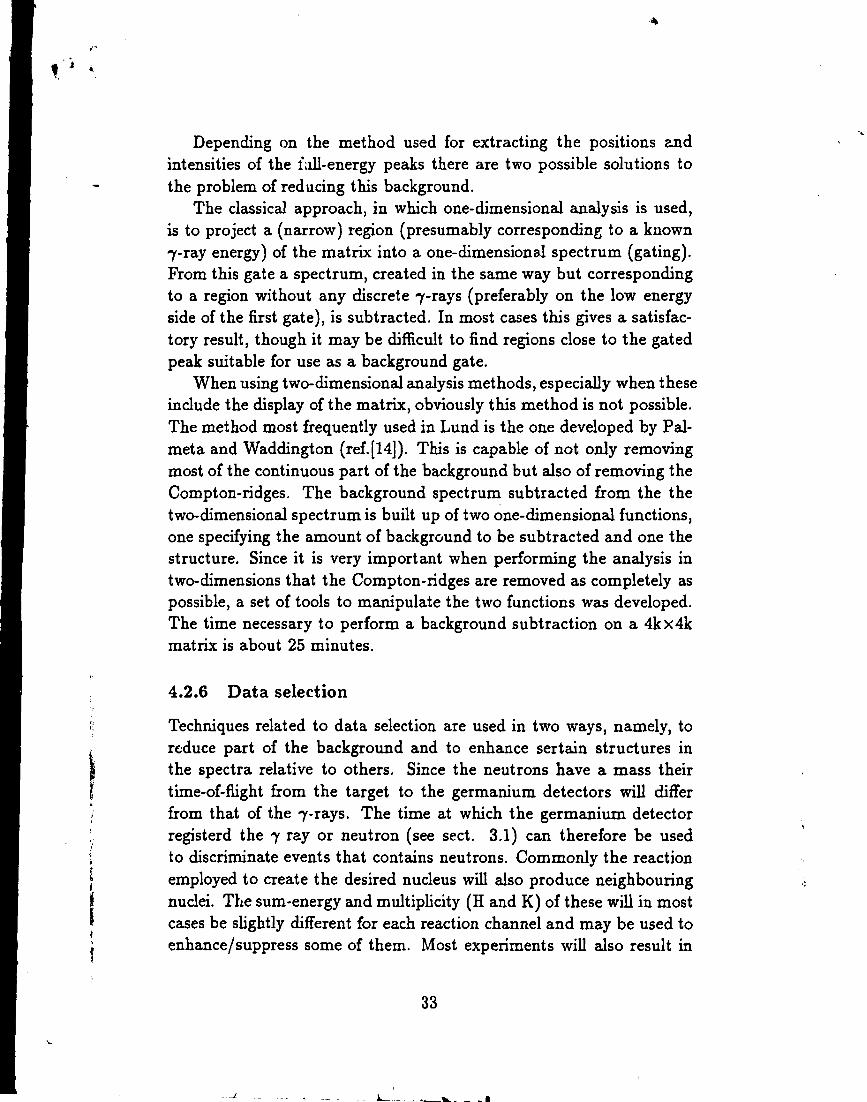
Depending on the method used for extracting the positions andintensities of the l\dl-energy peaks there are two possible solutions tothe problem of reducing this background.
The classical approach, in which one-dimensional analysis is used,is to project a (narrow) region (presumably corresponding to a known7-ray energy) of the matrix into a one-dimensional spectrum (gating).From this gate a spectrum, created in the same way but correspondingto a region without any discrete 7-rays (preferably on the low energyside of the first gate), is subtracted. In most cases this gives a satisfac-tory result, though it may be difficult to find regions close to the gatedpeak suitable for use as a background gate.
When using two-dimensional analysis methods, especially when theseinclude the display of the matrix, obviously this method is not possible.The method most frequently used in Lund is the one developed by Pal-meta and Waddington (ref. [14]). This is capable of not only removingmost of the continuous part of the background but also of removing theCompton-ridges. The background spectrum subtracted from the thetwo-dimensional spectrum is built up of two one-dimensional functions,one specifying the amount of background to be subtracted and one thestructure. Since it is very important when performing the analysis intwo-dimensions that the Compton-ridges are removed as completely aspossible, a set of tools to manipulate the two functions was developed.The time necessary to perform a background subtraction on a 4k x4kmatrix is about 25 minutes.
4.2.6 Data selection
Techniques related to data selection are used in two ways, namely, toreduce part of the background and to enhance sertain structures inthe spectra relative to others. Since the neutrons have a mass theirtime-of-flight from the target to the germanium detectors will differfrom that of the 7-rays. The time at which the germanium detectorregisterd the 7 ray or neutron (see sect. 3.1) can therefore be usedto discriminate events that contains neutrons. Commonly the reactionemployed to create the desired nucleus will also produce neighbouringnuclei. The sum-energy and multiplicity (H and K) of these will in mostcases be slightly different for each reaction channel and may be used toenhance/suppress some of them. Most experiments will also result in
33

coulumb-excitation of either the target or of the supporting material.Events originating from these reactions are effectively removed sincethe 7 ray multiplicity and sum energy is generally significantly lower.
4.3 Data analysisAs huge data sets became common, the developement of 7-coincidenceanalysis was forced to keep up to increase in pace. The very natureof the three-dimensional spectra and the vast amount of peaks to beextracted from them, demand new automatic tools of high confidence.Also data bases for the extracted data are in great demand, as wellas data bases describing the structure of the nucleus and programs toautomatically make comparisons with recorded spectra.
4.3.1 Analysis of 7-ray coincidence spectra
The classical way to analyze a two-dimensional 7-7 coincidence spec-trum (matrix) is to sum the contents of an energy range correspondingto one of the dimensions into a one-dimensional spectrum (gating) andto analyze this. This method has been used since the dawn of 7 spec-troscopy and a large number of tools, such as fitting, gating and plotprograms, has been developed for it. In this case the matrix is consid-ered as a large number of consecutive, one-dimensional spectra and notas a two-dimensional spectrum.
The approach in which the matrix is treated as a two-dimensionalspectrum gives rise not only to a whole new set of solutions to problemswhich are very difficult to solve in the classical approach, but also tomany new problems. The task of determining the position and intensityof all (« 10.000-50.000) peaks in such a matrix is a very lengthy andtiresome one and a program capable of extracting these data with ashigh confidence as manual work " 'tis a consummation devoutly to bewished".
42 - A program for two-dimensional analysisThe program "42" (ref.[15,16]) is a two-dimensional correspondence tothe interactive one-dimensional analysis programs. Instead of plotting athree-dimensional picture of the area under consideration, as would bethe extrapolation from the one-dimensional programs, it uses a colour
34
graphic display to colour-code the intensity. Since this coding is a verydelicate procedure, a method of expressing the intensity in terms ofthe uncertainty of the background (noise) was developed. This methodhas proved to be very useful, and without it the program would bemuch more difficult to use. The program is capable of performing a fulltwo-dimensional fit on an arbitrarily shaped area of the matrix and canalso perform center-of-mass calculations for circular and rectangularportions of hte matrix. In the task of verifying the presence or absenceof certain coincidences, the program has proved to be a particularlyefficient tool. There are also an option to save the operations performedin a session so that they can be repeated later on another matrix. Thisstrategem was developed for the analysis of angular correlations.
The importance of local backgroundAs mentioned earlier the uncertainty in the background is used to scalethe colour coding of the intensities of the peaks. This method givesthe colour scale a definite statistical meaning and is also used in analgorithm setting the gray scale in programs plotting portions of thematrix.
The idea behind this is to investigate the intensity distribution in apotion of the matrix, which may be denned as:
D(n) = £ 8n<M{7) (46)region
in which M(f) is the matrix value in the position r = (x, y). Or, inother words, D(n) is the number of channels with n counts. If the areaunder consideration contains only background, D(n) corresponds to thedistribution of the background.
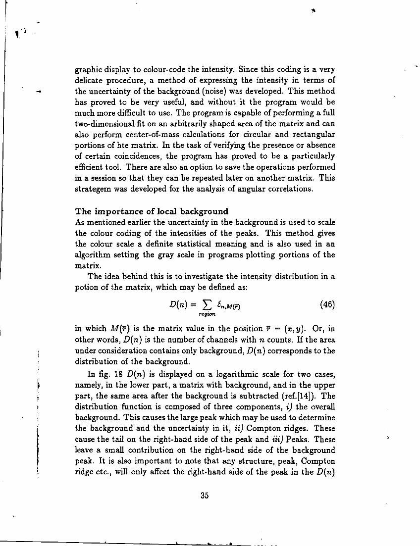
In fig. 18 D(n) is displayed on a logarithmic scale for two cases,namely, in the lower part, a matrix with background, and in the upperpart, the same area after the background is subtracted (ref.[14]). Thedistribution function is composed of three components, i) the overallbackground. This causes the large peak which may be used to determinethe background and the uncertainty in it, ii) Compton ridges. Thesecause the tail on the right-hand side of the peak and Hi) Peaks. Theseleave a small contribution on the right-hand side of the backgroundpeak. It is also important to note that any structure, peak, Comptonridge etc., will only affect the right-hand side of the peak in the D(n)
35

-100
Figure 18: D(n) fo. a 400 X 400 channel area.The upper spectrum corresponds to an area in a matrix from which the back-ground has been subtracted, and the lower corresponds to tne same area beforethe subtraction. The effect of the background subtraction is clearly seen: themean value of the background (the position of the peak) is moved down to0, and the large tail on the right hand side of the peak is erased. This tailcorresponds mainly to compton-ridges in the area. Also note that the peak inthe upper, subtracted, spectrum is very close of being symmetric as expectedif the background subtraction was correctly performed.
spectra. The left-hand side will always correspond to the uncertaintyin the background.
The D(n) function may also be used in order to check the result ofa background subtraction. This operation should result in a symmetricpeak corresponding to the background level in the D{n). If too muchbackground has been subtracted the peak would develop a tail on theleft-hand side as opposed to the right-hand side if the subtraction doesnot fully compensate for the background.
36

i'4
5 Experiments
5.1
This experiment is a part of a large number of experiments aiming tostudy the properties of rapidly rotating nuclei in the region 90 < N <100. These experiments were performed within the ESSA30 collabo-ration during a period of 18 months starting in September 1986. Theanalysis of the data was performed both in Lund and at Ris0, Denmark.
The nucleus was populated by the 146Nd(30Si,5n-4n)171-172W reactionat a beam energy of 160 MeV. Approximately 7% of the 210 millionevents collected were triple coincidences. These were used in order toestablish parts of the level scheme in which 7-7 coincidence techniqueswere ambiguous. For the analysis of 172W also a data set collected withthe TESSA3, using the same reaction though at lower beam energy, wasused. The level schemes of both nuclei were extended both concerningthe number of bands and in spin approximately to 3bh.
The interpretation of the rotational structures was compared withextensive calculations of band energies based on spin adiabatic and di-abatic energy surfaces. These nuclei are expected to have relativelystable deformations, offering a good example for testing cranking cal-culations. Although the (calculated) deformations were indeed found tobe stable, the small changes present was found to be crucial to explainthe behaviour of the nucleus.
In the case of 17lW, calculations of the 16 lowest quasiparticle states,corresponding to the possible combinations of parity and signature forboth neutrons and protons, show that transitions for each band areobserved only up to the point at which the band enters a region ofsignificantly higher level density.
Since this data set was the first analysed by the author, it has servedas a testing ground for developing analysis techniques. One of theresults of this is the program "42".
5.2 167Lu
Also this experiment is a part of the same systematic study as 171-172W.Approximately 130 million events were collected using the ESSA30 de-tector system and the existing level scheme was extended to approx-
37

imately 35 h. The reaction used was 123Sb(48Ca)4n)167Lu at a beamenergy of 206 MeV.
The frequencies of the band crossings together with the signaturedependence of the excitation energies and the measured B(M1)/B(E2)ratios, indicate a larger and more stable deformation than the threeclosest, even-N Lu isotopes (161>163-165Lu).
5.3 163TmThis nucleus was populated in high-spin states using two different re-actions, both performed at Ris0with the NORDBALL setup. A light ionbeam of 85 MeV 19F on 148Nd, resulted in 320 million double and tripleevents, which were collected with 20 germanium detectors to give thefirst data set. The second data set was the result the reaction of a heav-ier beam of 166 MeV 37C1 on 13OT1 from which more than 2 billion (!)events (double and triple) were collected using 20 germanium detectors(one of which an X-ray detector) and 39 of the 60 elements in the innerball.
These data sets have been (and are) used in several ways:i; investigation of the 7r/i9/2[541]l/2~ configuration andii; an attempt to establish the negative signature partner.in; analysis of the fluctuation of the background in order to investigatethe number of bands (ref. [17,18,19]) and possible differences due to thereaction creating the nucleus.iv] angular correlations to establish mixing ratios and spins.v; development of methods to handle huge data sets.
5.4 171ReAlthough this experiment is within the same study as the W and Luexperiments above, the data was collected using the TESSA3 setup.Approximately 60 million events from the reaction 123Sb(52Cr,4n)mReat 236 MeV were collected. Although the data set is small compared tothe 171-172W experiment mensioned above, the presence in the TESSA3setup of the inner ball, used for selection of the reaction channel, thedata sets are almost comparable in quality.
The rotational bands were extended to approximately 28 h. In theband identified as [402] | a second band crossing was found that is not
38

9 -fully understood in the CSM model. In the band identified as [515] |also the beginning of a second bandcrossing was found. The [660]^band has a gradual increase in the alignment before the bandcrossing, acharacter interpreted as a shape change, as the bandcrossing indicatesa weak interaction between the s and g bands.
39

v j
Acknowledgements
I would like to express my sincere gratitude to all persons i have hadthe opportunity to work together with, in one way or another, duringthe last few years.
In particular i would like to thank my senior supervisor, Professor HansRyde, who showed me, not only this particular field in physics but alsopatience and encouragement. There is always an area on his blackboardto be used for discussions.
A very special thank also to my second supervisor, Peter Ekström, whotaught me many things and brought me back whenever i got too carriedaway.
I would also like to thank Jaquette Lyttkens-Lindén, who introducedme to the analysis and together with Anna Brockstedt taught me to bethorough, Håkan Carlsson and Anders Nordlund, friends and compan-ions in the daily work.
I am very grateful to Ragnar Bengtsson and Tord Bengtsson at the de-partment of Mathematical Physics who never gave up to try to explainthe theory behind rapidly rotating nuclei.
Among all the people i have worked with at Ris0 in Denmark, I amespecially grateful to Bent Herskind for all his ideas, Gudrun Hagemannfor what she taught me, and Anders Holm for all our wild discussionson data acquisition systems at the black board.
My most sincere thanks to colleagues and friends at the division ofCosmic and Subatomic Physics for making each day at work a joy.
I am also very grateful to Karin Ryde who corrected my somewhatimaginative English.
I would also like to thank Professor Rydberg et al. for innumerousnocturnal discussions on allmost every topic imaginable.
Finally i would like to thank my father, whom i miss more than ever,my mother and my sister. Without Your support this would never havebeen possible.
40

References[1] F.S. Stevens, NX. Lark and R.M. Diamond. Nucl. Phys. 63 (1965)
82.
[2] S.G.Nilsson et al Nuc.Phys. A131 (1969) 432.
[3] B.R. Mottelson and S.G Nilsson, mat. Fys. Skr. Dan. Vid. Selsk.1 no. 8 (1959).
[4] B. Hahn, D.G. Ravenhall and R. Hofstadter. Phys. Rev. 101 (1956)500.
[5] R. Bengtsson, J.D. Garrett Lund-Mph-84/18 "The CrankingModel - Theoretical and Experimental Basis."
[6] C. Kittel. "Introduction to Solid-State Physics" Chap. 12. JohnWiley & sons (1976).
[7] J. Bardeen, L.N. Cooper and J.R. Schrieffer, Phys. Rev. 106 (1957)162.
[8] N.N. Bogoliubov Nuovo Cimento IIV-.6 (1958) 794.
[9] S.M. Harris, Phys Rev. 138 (1965) B509.
[10] R. Bass "Nuclear Reactions with Heavy Ions", Springer-Verlag.
[11] S.E. Arnell, H.A. Roth, O. Skeppstedt, J. Bialkowski, M. Moszyn-ski, D. Wolski, J. Nyberg, Nucl. Instr. and Meth A300 (1991)303.
[12] F. Liden, Nucl. Instr. and Meth. A288 (1990) 455.
[13] T. Kuroyanagi, S. Mitarai, S. Suematsu, B.J. Min, H. Tomura,J. Mukai, T. Maeda, R. Nakatani, G. Sletten, J. Nyberg, D. Jer-restam. Nucl. Instr. and Meth. A316 (1992) 289.
[14] Palmeta et Waddington, Nucl. Instr. and Meths. A234 (1984) 476.
[15] Bergström et Ekström, Nucl. Instr. and Meths. A301 (1991) 132.
[16] M. Bergström. Cosmic and Subatomic Physics ReportLUIP 9001(1990).
41

v J
[17] B. Herskind, T. Dossing and S. Leoni. Nucl. Phys. A520 (1990)539C.
[18] B. Herskind, A. Bracco, R.A. Broglia, T. T0ssing, A. Ikeda,S. Leoni, J. Lisle, M. Matsuo and E. Vigezzi. Phys. Rev. Lett.68 (1992) 3008.
[19] B. Herskind, T. T0ssing, D. Jerrestam, K. Shiffer, S. Leoni, J. Lisle,R. Chapman, F. Kazaie and J.N. Mo. Phys. Lett. 276B (1992) 4.
42