Embed Size (px)
Citation preview

K-TRONIC SERIES
Rev. 12/06Meiko • 917 Airpark Center Drive • Nashville, TN 37217 • Phone: (615) 399-6600 • (800) 55-MEIKO • Fax: (615) 399-6620
High Temperature Sanitizing Rack Conveyor Dishwashers(USA Version)
OWNER’S INSTALLATION, OPERATION ANDMAINTENANCE MANUAL
Models:• K-200 • K-200 LPW • K-400 PW• K-200 PW • K-400 • K-400 LPW
Page 2
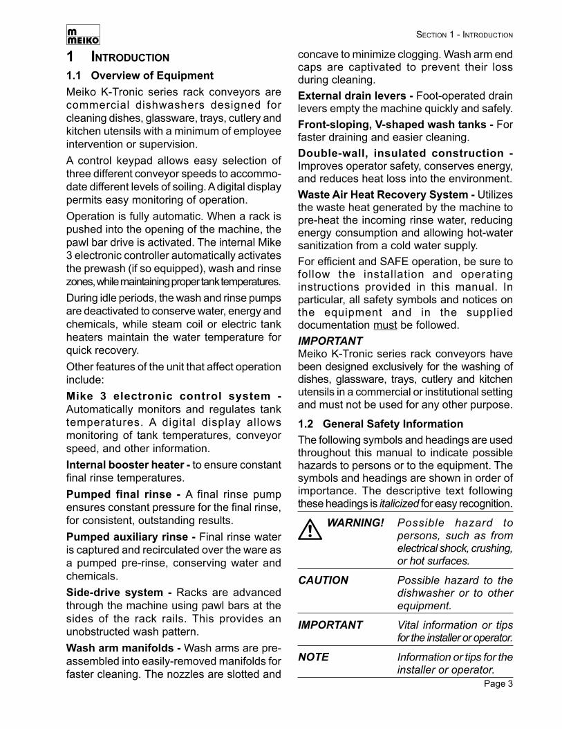
TABLE OF CONTENTS or Dispensers .......................................... 133.13 Fresh Water Supply Connections ............ 133.14 Steam System Connections .................... 143.15 Drain Connection ..................................... 153.16 Final Assembly ........................................ 15
4. OPERATION ....................................... 184.1 Location and Description of Controls ....... 184.2 Startup ..................................................... 204.3 Loading .................................................... 214.4 Operation ................................................. 224.5 Idle Periods ............................................. 224.6 Clearing Jams.......................................... 234.7 Shutdown ................................................ 23
5. CLEANING ......................................... 245.1 Daily Cleaning (or as required) ................ 245.2 Weekly Cleaning (or as required) ............ 265.3 Exterior Cleaning (as required) ................ 265.4 Deliming (as required) ............................. 28
6. TROUBLESHOOTING ........................ 29
1. INTRODUCTION ................................. 31.1 Overview of Equipment ............................. 31.2 General Safety Information........................ 3
2. TRANSPORT AND SHIPPING ............ 4
3. INSTALLATION .................................... 43.1 Overview of Installation ............................. 43.2 Requirements Before Installation .............. 53.3 Uncrating, Positioning and Leveling ............. 63.4 Tabling Attachment .................................... 83.5 Accessing the Utility Connections ............. 83.6 Vent Connection ........................................ 93.7 Main Electrical Supply Connection .......... 103.8 Dispensing System Overview .................. 113.9 Installing an External Solid or Liquid
Detergent System .................................... 123.10 Installing an External Liquid Rinse
Aid System .............................................. 123.11 Wiring External Chemical Dispensing
Systems ................................................... 133.12 Connecting Chemical Containers
MEIKO K-SERIES RACK CONVEYOR DISHWASHERS HAVE BEEN DESIGNED EXCLUSIVELYFOR THE WASHING OF DISHES, GLASSWARE, CUTLERY, KITCHEN UTENSILS AND TRAYS
IN A COMMERCIAL OR INSTITUTIONAL SETTING AND MUST NOT BE USED FOR ANYOTHER PURPOSE WITHOUT THE WRITTEN PERMISSION OF MEIKO.
Meiko reserves the right to change any specifications without notice at any time.
MEIKO ACCEPTS NO RESPONSIBILITY FOR DAMAGE TO THE APPLIANCE, SURROUNDINGEQUIPMENT OR ENVIRONMENT THAT IS CAUSED BY INAPPROPRIATE INSTALLATION OR
OPERATION, OR FROM ANY SERVICE THAT IS UNDERTAKEN BY NON-AUTHORIZEDPERSONNEL, OR FROM THE USE OF ANY PARTS EXCEPT THOSE THAT ARE APPROVED
BY THE MANUFACTURER. ANY SUCH INSTALLATION, USE OR SERVICE WILL IMMEDIATELYVOID THE MANUFACTURER’S WARRANTY.
Meiko • 917 Airpark Center Drive • Nashville, TN 37217Phone: (615) 399-6600 • (800) 55-MEIKO • Fax: (615) 399-6620www.meiko.us
ANY MODIFICATIONS TO THE APPLIANCE THAT ARE PERFORMED WITHOUT THE WRITTENPERMISSION OF MEIKO WILL IMMEDIATELY VOID THE MANUFACTURER’S WARRANTY.
AN ELECTRICAL WIRING DIAGRAM IS LOCATED INSIDE THE CONTROL BOX OF THIS MACHINE.
Page 3
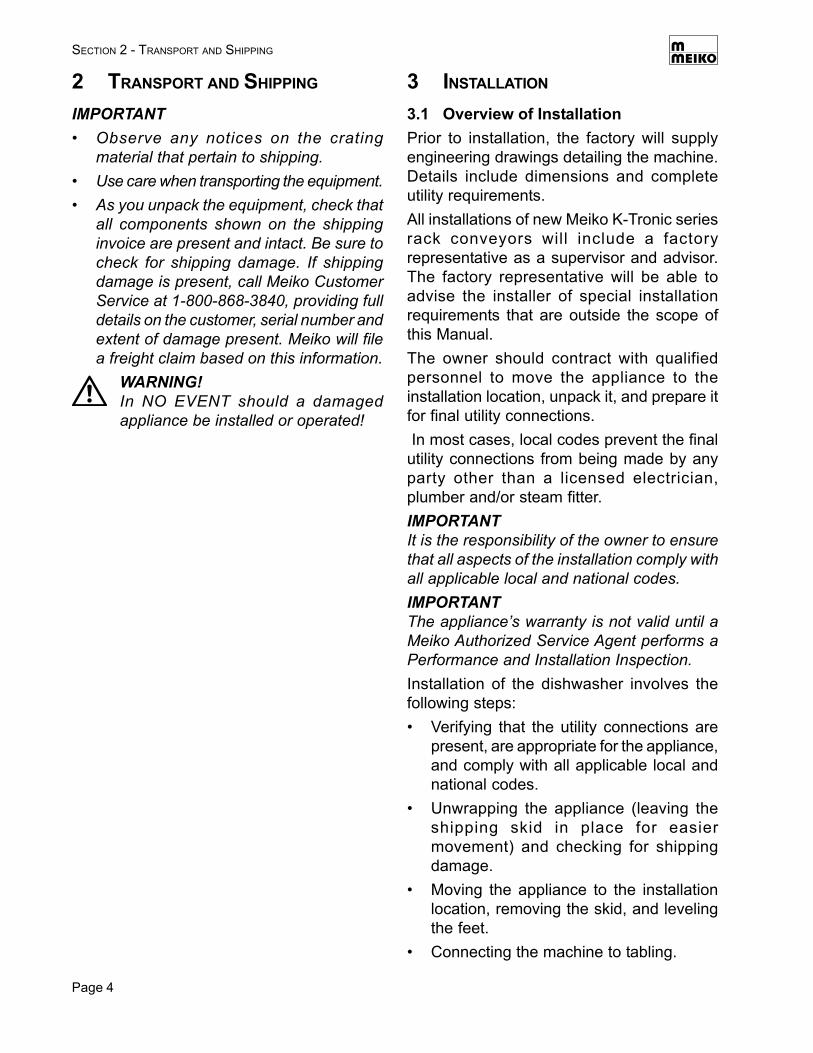
concave to minimize clogging. Wash arm endcaps are captivated to prevent their lossduring cleaning.External drain levers - Foot-operated drainlevers empty the machine quickly and safely.Front-sloping, V-shaped wash tanks - Forfaster draining and easier cleaning.Double-wall, insulated construction -Improves operator safety, conserves energy,and reduces heat loss into the environment.Waste Air Heat Recovery System - Utilizesthe waste heat generated by the machine topre-heat the incoming rinse water, reducingenergy consumption and allowing hot-watersanitization from a cold water supply.For efficient and SAFE operation, be sure tofollow the installation and operatinginstructions provided in this manual. Inparticular, all safety symbols and notices onthe equipment and in the supplieddocumentation must be followed.IMPORTANTMeiko K-Tronic series rack conveyors havebeen designed exclusively for the washing ofdishes, glassware, trays, cutlery and kitchenutensils in a commercial or institutional settingand must not be used for any other purpose.
1.2 General Safety InformationThe following symbols and headings are usedthroughout this manual to indicate possiblehazards to persons or to the equipment. Thesymbols and headings are shown in order ofimportance. The descriptive text followingthese headings is italicized for easy recognition.
WARNING! Possible hazard topersons, such as fromelectrical shock, crushing,or hot surfaces.
CAUTION Possible hazard to thedishwasher or to otherequipment.
IMPORTANT Vital information or tipsfor the installer or operator.
NOTE Information or tips for theinstaller or operator.
SECTION 1 - INTRODUCTION
1 INTRODUCTION
1.1 Overview of EquipmentMeiko K-Tronic series rack conveyors arecommercial dishwashers designed forcleaning dishes, glassware, trays, cutlery andkitchen utensils with a minimum of employeeintervention or supervision.A control keypad allows easy selection ofthree different conveyor speeds to accommo-date different levels of soiling. A digital displaypermits easy monitoring of operation.Operation is fully automatic. When a rack ispushed into the opening of the machine, thepawl bar drive is activated. The internal Mike3 electronic controller automatically activatesthe prewash (if so equipped), wash and rinsezones, while maintaining proper tank temperatures.During idle periods, the wash and rinse pumpsare deactivated to conserve water, energy andchemicals, while steam coil or electric tankheaters maintain the water temperature forquick recovery.Other features of the unit that affect operationinclude:Mike 3 electronic control system -Automatically monitors and regulates tanktemperatures. A digital display allowsmonitoring of tank temperatures, conveyorspeed, and other information.Internal booster heater - to ensure constantfinal rinse temperatures.Pumped final rinse - A final rinse pumpensures constant pressure for the final rinse,for consistent, outstanding results.Pumped auxiliary rinse - Final rinse wateris captured and recirculated over the ware asa pumped pre-rinse, conserving water andchemicals.Side-drive system - Racks are advancedthrough the machine using pawl bars at thesides of the rack rails. This provides anunobstructed wash pattern.Wash arm manifolds - Wash arms are pre-assembled into easily-removed manifolds forfaster cleaning. The nozzles are slotted and
Page 4
2 TRANSPORT AND SHIPPING
IMPORTANT• Observe any notices on the crating
material that pertain to shipping.• Use care when transporting the equipment.• As you unpack the equipment, check that
all components shown on the shippinginvoice are present and intact. Be sure tocheck for shipping damage. If shippingdamage is present, call Meiko CustomerService at 1-800-868-3840, providing fulldetails on the customer, serial number andextent of damage present. Meiko will filea freight claim based on this information.
WARNING!In NO EVENT should a damagedappliance be installed or operated!
SECTION 2 - TRANSPORT AND SHIPPING
3 INSTALLATION
3.1 Overview of InstallationPrior to installation, the factory will supplyengineering drawings detailing the machine.Details include dimensions and completeutility requirements.All installations of new Meiko K-Tronic seriesrack conveyors will include a factoryrepresentative as a supervisor and advisor.The factory representative will be able toadvise the installer of special installationrequirements that are outside the scope ofthis Manual.The owner should contract with qualifiedpersonnel to move the appliance to theinstallation location, unpack it, and prepare itfor final utility connections. In most cases, local codes prevent the finalutility connections from being made by anyparty other than a licensed electrician,plumber and/or steam fitter.IMPORTANTIt is the responsibility of the owner to ensurethat all aspects of the installation comply withall applicable local and national codes.IMPORTANTThe appliance’s warranty is not valid until aMeiko Authorized Service Agent performs aPerformance and Installation Inspection.Installation of the dishwasher involves thefollowing steps:• Verifying that the utility connections are
present, are appropriate for the appliance,and comply with all applicable local andnational codes.
• Unwrapping the appliance (leaving theshipping skid in place for easiermovement) and checking for shippingdamage.
• Moving the appliance to the installationlocation, removing the skid, and levelingthe feet.
• Connecting the machine to tabling.
Page 5
SECTION 3 - INSTALLATION
• Routing the ventilation system inaccordance with the factory-suppliedengineering drawings and all applicablelocal and national codes.
• Connecting the water supply.• Connecting the electrical supply.• Connecting the steam supply line (for
machines with steam heating).• Connecting the steam condensate return
line, and routing it to either a floor drain ora building condensate return line (formachines with steam heating).
• Connecting the drain line, and routing itto a floor drain or building drain.
• Installing the chemical dispensing system(if so equipped), following the manu-facturer’s instructions AND the instructionsin Section 3 of this Manual.
• Contacting your Meiko Authorized ServiceAgent to perform a Performance andInstallation Inspection for the machine.This step also validates the machine’swarranty.Meiko may be able to arrange for anAuthorized Service Agent to be presentat the conclusion of the installationprocess. Consult your Authorized SalesRepresentative for details.
3.2 Requirements Before InstallationBefore the installer can uncrate and move theappliance to the installation location, thefollowing conditions MUST be met:• INSTALLATION AREA REQUIREMENTS
- The area MUST be frost-free. Freezingtemperatures (32°F/0°C or lower)inhibit proper operation and candamage internal components.
- The area MUST have a firm floorsurface. It is possible to compensatefor uneven flooring by adjusting thefeet.
- The area should be away fromappliances, furniture or surfaces thatcan be damaged by steam. If this is
not possible, these items should beprotected from the steam that isreleased during normal operation ofthe dishwasher.
• UTILTITY CONNECTION REQUIREMENTS- Connections must be present and
ready for hookup to the appliance. Allutility supplies must comply with theelectrical information labels, with theinformation on the data plate, and withall applicable local and national codes.
- Electrical leads, water supply line(s),drain line, and the steam supply andcondensate return lines (if soequipped) must be present.
- The electrical supply must match thevoltage and amperage requirementsspecified on the data plate. Circuitbreakers/disconnects (lockout/tagoutis strongly recommended) must beinstalled in accordance with all localand national codes. If the machineincludes multiple electrical connec-tions, each supply must include adedicated circuit breaker/disconnect.
- The water supplies must match thetemperatures, pressures and flowrates specified on the data plate. Forbest operation, it should also match thewater hardness specified on theengineering drawings.
- The steam supply (if so equipped)must match the pressure and volumespecified on the data plate.
- The ventilation system must bepresent and in accordance with thefactory-supplied engineering drawingsand all applicable local and nationalcodes.
- For units using a chemical dispensingsystem, appropriate dispensers orcontainers should be installed andready for connection to the appliance.
• GENERAL REQUIREMENTSAuthorized personnel should be availableto perform the actual utility connections.
Page 6
3.3 Uncrating, Positioning and LevelingIMPORTANTMost K-Tronic series machines are shippedin a single section, with wiring and plumbingconnections already in place from the factory.The Installation section of this manualdescribes the installation of these pre-assembled machines.Due to space limitations at some installationsites, it may be necessary for the machine tobe shipped in sections. If this is the case,assembling the sections is outside the scopeof this Manual. Follow the on-site directionsof the Meiko factory representative toassemble the sections.1. Remove all shipping and packaging ma-
terial from the appliance, including sup-ports and wrappings. Leave the shippingskid in place at this time to allow for easiermovement to the installation location.
2. Check for shipping damage as describedin Section 2, “Transport and Shipping.” Ifdamage is present, call Meiko CustomerService at 1-800-868-3840, providing fulldetails on the customer, serial number andextent of damage present. Meiko will filea freight claim based on this information.
3. Move the appliance to the installation areausing proper moving equipment.CAUTIONWhen moving the machine, ALWAYS sup-port it from both ends - not the center.
SECTION 3 - INSTALLATION
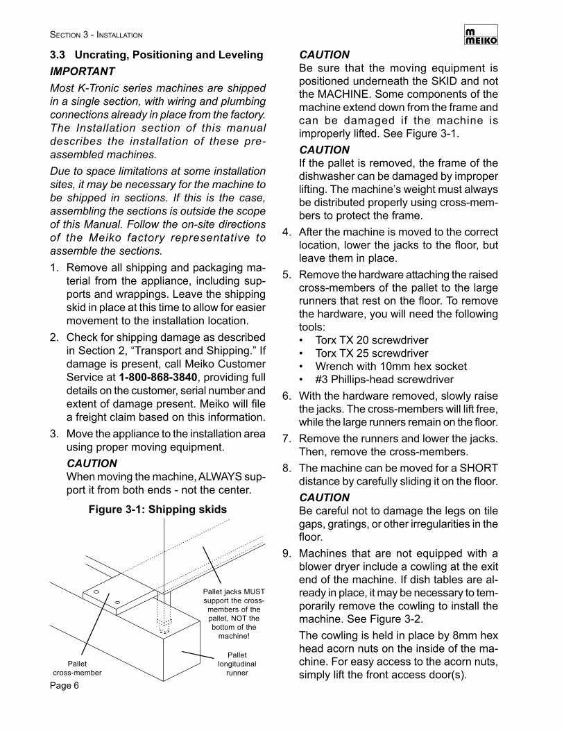
CAUTIONBe sure that the moving equipment ispositioned underneath the SKID and notthe MACHINE. Some components of themachine extend down from the frame andcan be damaged if the machine isimproperly lifted. See Figure 3-1.CAUTIONIf the pallet is removed, the frame of thedishwasher can be damaged by improperlifting. The machine’s weight must alwaysbe distributed properly using cross-mem-bers to protect the frame.
4. After the machine is moved to the correctlocation, lower the jacks to the floor, butleave them in place.
5. Remove the hardware attaching the raisedcross-members of the pallet to the largerunners that rest on the floor. To removethe hardware, you will need the followingtools:• Torx TX 20 screwdriver• Torx TX 25 screwdriver• Wrench with 10mm hex socket• #3 Phillips-head screwdriver
6. With the hardware removed, slowly raisethe jacks. The cross-members will lift free,while the large runners remain on the floor.
7. Remove the runners and lower the jacks.Then, remove the cross-members.
8. The machine can be moved for a SHORTdistance by carefully sliding it on the floor.CAUTIONBe careful not to damage the legs on tilegaps, gratings, or other irregularities in thefloor.
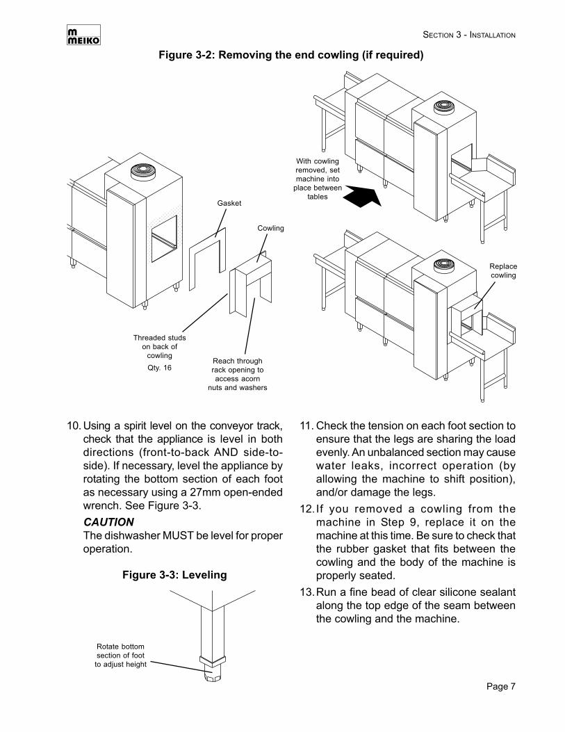
9. Machines that are not equipped with ablower dryer include a cowling at the exitend of the machine. If dish tables are al-ready in place, it may be necessary to tem-porarily remove the cowling to install themachine. See Figure 3-2.The cowling is held in place by 8mm hexhead acorn nuts on the inside of the ma-chine. For easy access to the acorn nuts,simply lift the front access door(s).
Figure 3-1: Shipping skids
Palletcross-member
Palletlongitudinal
runner
Pallet jacks MUSTsupport the cross-members of thepallet, NOT thebottom of the
machine!
Page 7
10. Using a spirit level on the conveyor track,check that the appliance is level in bothdirections (front-to-back AND side-to-side). If necessary, level the appliance byrotating the bottom section of each footas necessary using a 27mm open-endedwrench. See Figure 3-3.CAUTIONThe dishwasher MUST be level for properoperation.
SECTION 3 - INSTALLATION
11. Check the tension on each foot section toensure that the legs are sharing the loadevenly. An unbalanced section may causewater leaks, incorrect operation (byallowing the machine to shift position),and/or damage the legs.
12.If you removed a cowling from themachine in Step 9, replace it on themachine at this time. Be sure to check thatthe rubber gasket that fits between thecowling and the body of the machine isproperly seated.
13.Run a fine bead of clear silicone sealantalong the top edge of the seam betweenthe cowling and the machine.
Figure 3-3: Leveling
Rotate bottomsection of footto adjust height
Figure 3-2: Removing the end cowling (if required)
Threaded studson back of
cowlingQty. 16
Cowling
Gasket
Reach throughrack opening toaccess acorn
nuts and washers
With cowlingremoved, setmachine into
place betweentables
Replacecowling
Page 8
SECTION 3 - INSTALLATION
3.4 Tabling Attachment
1. Position the table lip-in at both ends of themachine, as shown in Figure 3-4. Be sureto seat the lip-in against the inner face ofthe sidewall of the dishwasher.
• Check that the surface height of eachtable matches the height of the racktrack of the dishwasher, to ensure asmooth transition. The standard tablesurface height is 34” (864mm).
• Check that the dishmachine is level.The height of the dishmachine, and ofmost tables, can be adjusted by rotatingthe feet at the end of the legs.CAUTIONAfter adjusting the height of thedishmachine, always check that it is levelto ensure proper operation.
3. After the tables have been positionedcorrectly, secure them to the dishwasherusing silicone sealant.
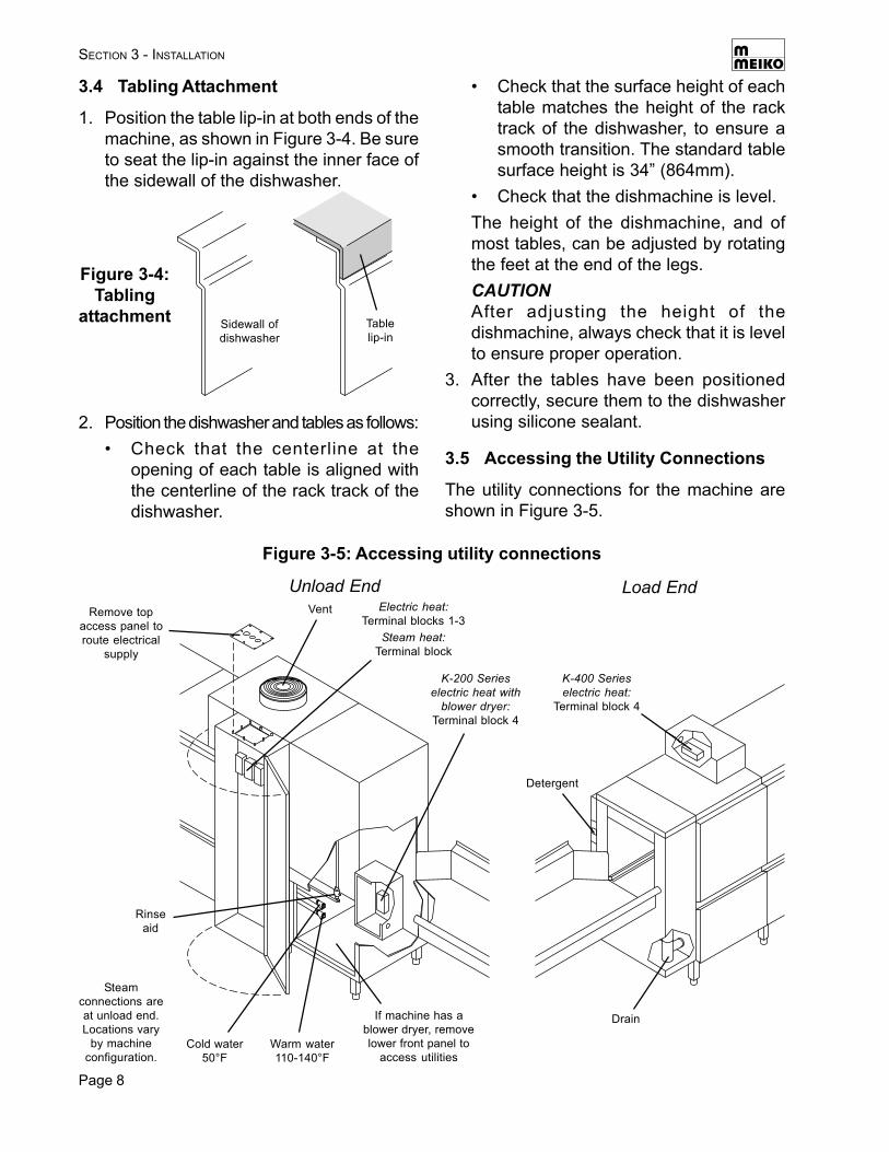
3.5 Accessing the Utility Connections
The utility connections for the machine areshown in Figure 3-5.
2. Position the dishwasher and tables as follows:• Check that the centerline at the
opening of each table is aligned withthe centerline of the rack track of thedishwasher.
Figure 3-4:Tabling
attachment Sidewall ofdishwasher
Tablelip-in
Figure 3-5: Accessing utility connections
Electric heat:Terminal blocks 1-3
Steam heat:Terminal block
Remove topaccess panel toroute electrical
supply
Unload EndVent
K-200 Serieselectric heat with
blower dryer:Terminal block 4
Warm water110-140°F
Cold water50°F
Rinseaid
If machine has ablower dryer, removelower front panel to
access utilities
Steamconnections areat unload end.Locations vary
by machineconfiguration.
Load End
K-400 Serieselectric heat:
Terminal block 4
Detergent
Drain
Page 9
C O N T R O LC O N T R O LC O N T R O L
controlled
SECTION 3 - INSTALLATION
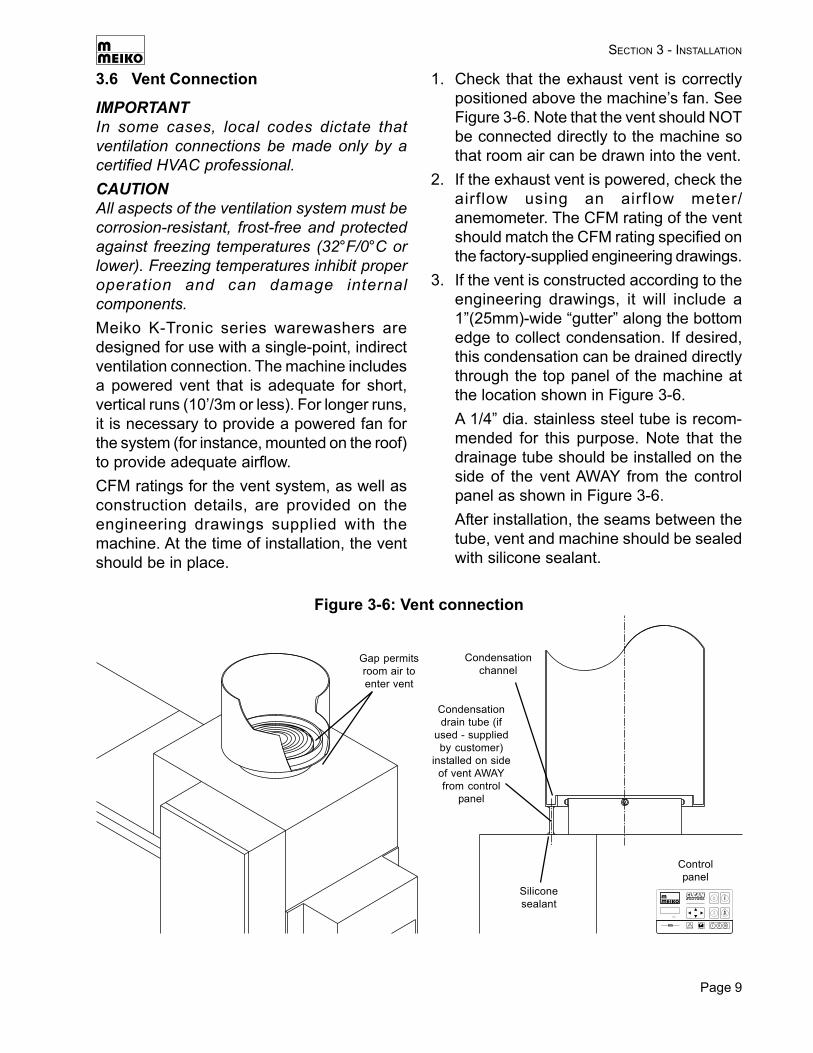
3.6 Vent Connection
IMPORTANTIn some cases, local codes dictate thatventilation connections be made only by acertified HVAC professional.CAUTIONAll aspects of the ventilation system must becorrosion-resistant, frost-free and protectedagainst freezing temperatures (32°F/0°C orlower). Freezing temperatures inhibit properoperation and can damage internalcomponents.Meiko K-Tronic series warewashers aredesigned for use with a single-point, indirectventilation connection. The machine includesa powered vent that is adequate for short,vertical runs (10’/3m or less). For longer runs,it is necessary to provide a powered fan forthe system (for instance, mounted on the roof)to provide adequate airflow.CFM ratings for the vent system, as well asconstruction details, are provided on theengineering drawings supplied with themachine. At the time of installation, the ventshould be in place.
1. Check that the exhaust vent is correctlypositioned above the machine’s fan. SeeFigure 3-6. Note that the vent should NOTbe connected directly to the machine sothat room air can be drawn into the vent.
2. If the exhaust vent is powered, check theairflow using an airflow meter/anemometer. The CFM rating of the ventshould match the CFM rating specified onthe factory-supplied engineering drawings.
3. If the vent is constructed according to theengineering drawings, it will include a1”(25mm)-wide “gutter” along the bottomedge to collect condensation. If desired,this condensation can be drained directlythrough the top panel of the machine atthe location shown in Figure 3-6.A 1/4” dia. stainless steel tube is recom-mended for this purpose. Note that thedrainage tube should be installed on theside of the vent AWAY from the controlpanel as shown in Figure 3-6.After installation, the seams between thetube, vent and machine should be sealedwith silicone sealant.
Figure 3-6: Vent connection
Condensationchannel
Gap permitsroom air toenter vent
Condensationdrain tube (if
used - suppliedby customer)
installed on sideof vent AWAYfrom control
panel
Siliconesealant
Controlpanel
Page 10
SECTION 3 - INSTALLATION
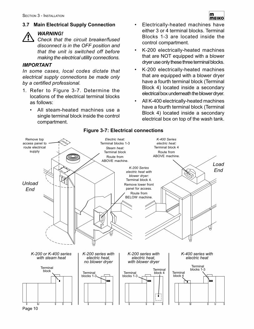
3.7 Main Electrical Supply Connection
WARNING!Check that the circuit breaker/fuseddisconnect is in the OFF position andthat the unit is switched off beforemaking the electrical utility connections.
IMPORTANTIn some cases, local codes dictate thatelectrical supply connections be made onlyby a certified professional.1. Refer to Figure 3-7. Determine the
locations of the electrical terminal blocksas follows:• All steam-heated machines use a
single terminal block inside the controlcompartment.
• Electrically-heated machines haveeither 3 or 4 terminal blocks. TerminalBlocks 1-3 are located inside thecontrol compartment.
• K-200 electrically-heated machinesthat are NOT equipped with a blowerdryer use only these three terminal blocks.
• K-200 electrically-heated machinesthat are equipped with a blower dryerhave a fourth terminal block (TerminalBlock 4) located inside a secondaryelectrical box underneath the blower dryer.
• All K-400 electrically-heated machineshave a fourth terminal block (TerminalBlock 4) located inside a secondaryelectrical box on top of the wash tank.
Figure 3-7: Electrical connectionsElectric heat:
Terminal blocks 1-3Steam heat:
Terminal blockRoute from
ABOVE machine.
Remove topaccess panel toroute electrical
supply
UnloadEnd
K-200 Serieselectric heat with
blower dryer:Terminal block 4.
Remove lower frontpanel for access.
Route fromBELOW machine.
LoadEnd
K-400 Serieselectric heat:
Terminal block 4Route from
ABOVE machine.
Terminalblock
K-200 or K-400 serieswith steam heat
K-200 series withelectric heat,
no blower dryer
Terminalblocks 1-3
K-200 series withelectric heat,
with blower dryer
Terminalblocks 1-3
Terminalblock 4
K-400 series withelectric heat
Terminalblocks 1-3
Terminalblock 4
Page 11
SECTION 3 - INSTALLATION
2. Check that the incoming power leads areof sufficient rating for the appliance’scurrent draw. Amperage and minimumsupply wire specifications are shown onthe wiring diagram, the serial plate andthe electrical information label(s) next toeach terminal block.
3. Remove the top access panel from thecontrol compartment as shown in Figure 3-7.
4. Fit seal-tight fittings or strain reliefs intothe holes in the access panel for theelectrical supply wires as necessary.Three holes are provided. Each electricalsupply should be routed through its ownstrain relief.
5. Route the electrical leads to the controlcompartment. All electrical supplies thatwill be connected to terminal blocks insidethe control compartment should be routedfrom ABOVE the machine, if possible.
6. Refer to the electrical wiring diagram andthe electrical information labels next to theterminal block(s). Connect the powersupply and ground leads to the terminalblock(s) inside the control compartmentas indicated.
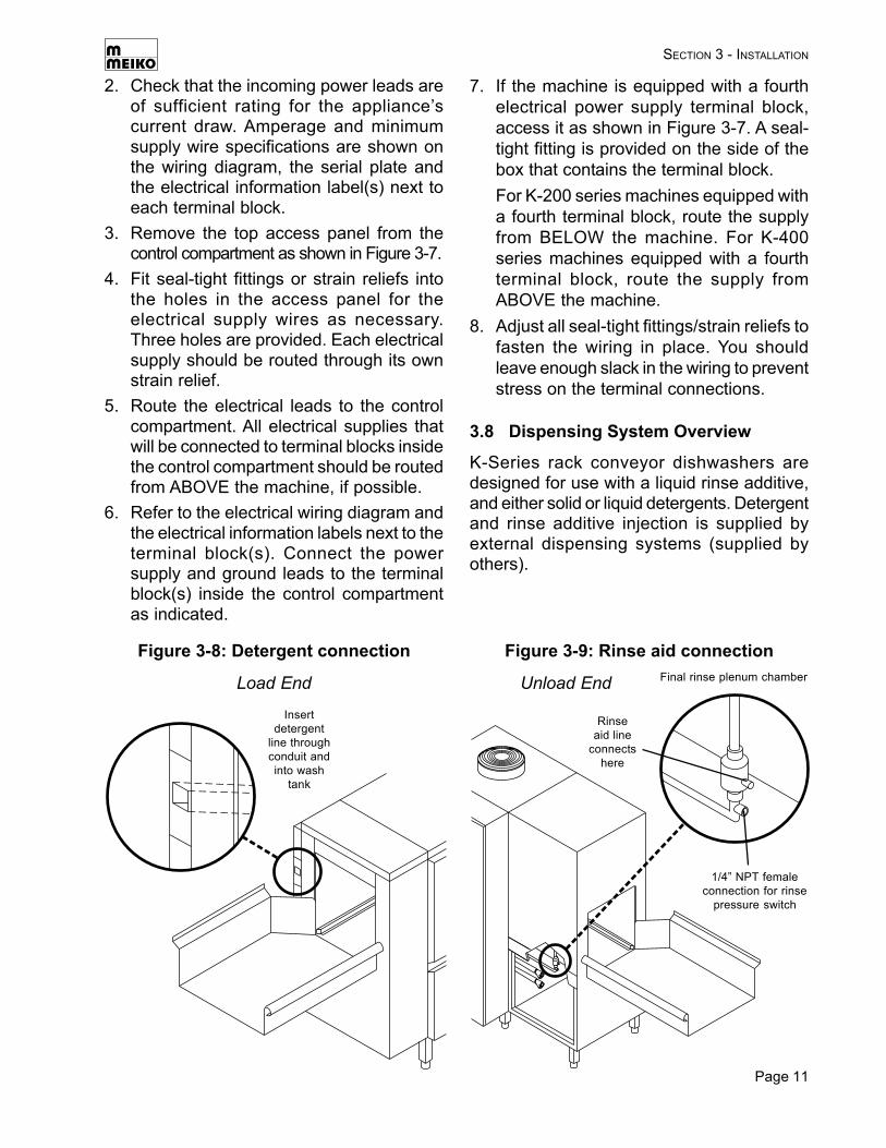
3.8 Dispensing System Overview
K-Series rack conveyor dishwashers aredesigned for use with a liquid rinse additive,and either solid or liquid detergents. Detergentand rinse additive injection is supplied byexternal dispensing systems (supplied byothers).
7. If the machine is equipped with a fourthelectrical power supply terminal block,access it as shown in Figure 3-7. A seal-tight fitting is provided on the side of thebox that contains the terminal block.For K-200 series machines equipped witha fourth terminal block, route the supplyfrom BELOW the machine. For K-400series machines equipped with a fourthterminal block, route the supply fromABOVE the machine.
8. Adjust all seal-tight fittings/strain reliefs tofasten the wiring in place. You shouldleave enough slack in the wiring to preventstress on the terminal connections.
Figure 3-8: Detergent connection Figure 3-9: Rinse aid connection
Load End
Insertdetergent
line throughconduit andinto wash
tank
Unload End Final rinse plenum chamber
1/4” NPT femaleconnection for rinse
pressure switch
Rinseaid line
connectshere
Page 12
SECTION 3 - INSTALLATION
The machine is equipped with:• A pre-plumbed tubing raceway exiting the
machine at the load end of the machine(see Figure 3-8). The raceway is routed todeliver detergent into the wash tank. Solidor liquid detergent lines can be routeddown the raceway and into the tank.
• A dummy plug in the floor of the wash tankthat permits the installation of a detergentconcentration probe.
• A final rinse plenum chamber with a fittingfor a liquid rinse aid line (see Figure 3-9).A threaded pipe connection just below theplenum allows the installation of a finalrinse pressure switch.
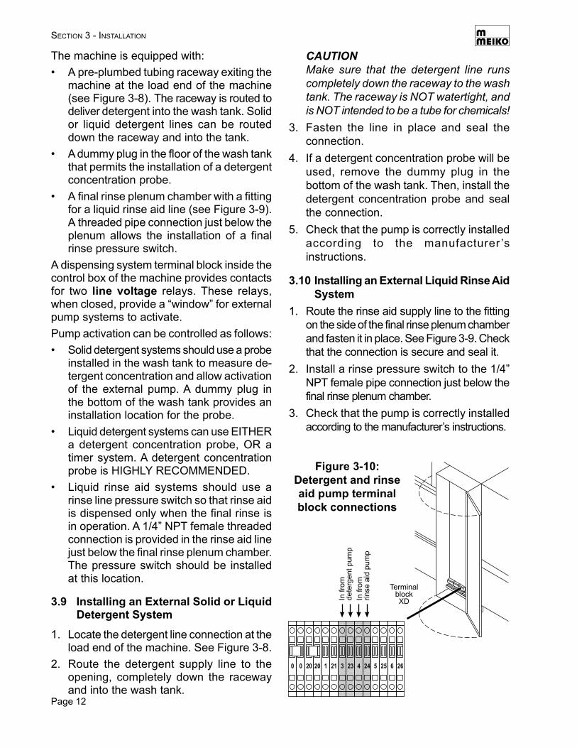
A dispensing system terminal block inside thecontrol box of the machine provides contactsfor two line voltage relays. These relays,when closed, provide a “window” for externalpump systems to activate.Pump activation can be controlled as follows:• Solid detergent systems should use a probe
installed in the wash tank to measure de-tergent concentration and allow activationof the external pump. A dummy plug inthe bottom of the wash tank provides aninstallation location for the probe.
• Liquid detergent systems can use EITHERa detergent concentration probe, OR atimer system. A detergent concentrationprobe is HIGHLY RECOMMENDED.
• Liquid rinse aid systems should use arinse line pressure switch so that rinse aidis dispensed only when the final rinse isin operation. A 1/4” NPT female threadedconnection is provided in the rinse aid linejust below the final rinse plenum chamber.The pressure switch should be installedat this location.
3.9 Installing an External Solid or LiquidDetergent System
1. Locate the detergent line connection at theload end of the machine. See Figure 3-8.
2. Route the detergent supply line to theopening, completely down the racewayand into the wash tank.
CAUTIONMake sure that the detergent line runscompletely down the raceway to the washtank. The raceway is NOT watertight, andis NOT intended to be a tube for chemicals!
3. Fasten the line in place and seal theconnection.
4. If a detergent concentration probe will beused, remove the dummy plug in thebottom of the wash tank. Then, install thedetergent concentration probe and sealthe connection.
5. Check that the pump is correctly installedaccording to the manufacturer ’sinstructions.
3.10 Installing an External Liquid Rinse AidSystem
1. Route the rinse aid supply line to the fittingon the side of the final rinse plenum chamberand fasten it in place. See Figure 3-9. Checkthat the connection is secure and seal it.
2. Install a rinse pressure switch to the 1/4”NPT female pipe connection just below thefinal rinse plenum chamber.
3. Check that the pump is correctly installedaccording to the manufacturer’s instructions.
2000 21120 3 24423 6255 26
Infr
om
dete
rgentpum
p
Infr
om
rinse
aid
pum
p
TerminalblockXD
Figure 3-10:Detergent and rinseaid pump terminalblock connections
Page 13
SECTION 3 - INSTALLATION
3.12 Connecting Chemical Containers orDispensers
This section applies to units with either inter-nal or external chemical dispensing pumps.1. Check that the rinse additive and
detergent are compatible with the unit. Inparticular, a commercial (not a domestic)detergent MUST be used.
2 Check that the containers/dispensers arecorrectly installed according to themanufacturer’s instructions.
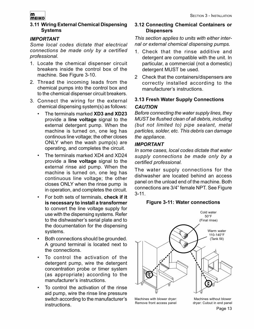
3.13 Fresh Water Supply ConnectionsCAUTIONBefore connecting the water supply lines, theyMUST be flushed clean of all debris, including(but not limited to) pipe sealant, metalparticles, solder, etc. This debris can damagethe appliance.IMPORTANTIn some cases, local codes dictate that watersupply connections be made only by acertified professional.The water supply connections for thedishwasher are located behind an accesspanel on the unload end of the machine. Bothconnections are 3/4” female NPT. See Figure3-11.
3.11 Wiring External Chemical DispensingSystems
IMPORTANTSome local codes dictate that electricalconnections be made only by a certifiedprofessional.1. Locate the chemical dispenser circuit
breakers inside the control box of themachine. See Figure 3-10.
2. Thread the incoming leads from thechemical pumps into the control box andto the chemical dispenser circuit breakers.
3. Connect the wiring for the externalchemical dispensing system(s) as follows:• The terminals marked XD3 and XD23
provide a line voltage signal to theexternal detergent pump. When themachine is turned on, one leg hascontinous line voltage; the other closesONLY when the wash pump(s) areoperating, and completes the circuit.
• The terminals marked XD4 and XD24provide a line voltage signal to theexternal rinse aid pump. When themachine is turned on, one leg hascontinuous line voltage; the othercloses ONLY when the rinse pump isin operation, and completes the circuit.
• For both sets of terminals, check if itis necessary to install a transformerto convert the line voltage supply foruse with the dispensing systems. Referto the dishwasher’s serial plate and tothe documentation for the dispensingsystems.
• Both connections should be grounded.A ground terminal is located next tothe connections.
• To control the activation of thedetergent pump, wire the detergentconcentration probe or timer system(as appropriate) according to themanufacturer’s instructions.
• To control the activation of the rinseaid pump, wire the rinse line pressureswitch according to the manufacturer’sinstructions.
Figure 3-11: Water connections
Warm water110-140°F(Tank fill)
Cold water50°F
(Final rinse)
Machines with blower dryer:Remove front access panel
Machines without blowerdryer: Cutout in end panel
Page 14
1. Check that iron or other metal particlescannot contaminate the fresh watersupplied to the dishwasher.
2. Check the incoming water temperature.• The final rinse line should be
approximately 50°F for optimaloperation. This water is circulatedthrough the machine’s waste air heatrecovery system and routed to theinternal booster heater for the final riseto 180°F.
• The tank fill line should be 110-140°Fto reduce the machine’s preheat time.
3. Check the incoming water hardness.Meiko recommends a hardness of 4 grainsper U.S. gallon (7 DH German hardness).
4. Check that the water flow on the final rinseline is adequate. All K-Tronic seriesmachines have a final rinse flow rate of1.42 U.S. gallons per minute (84.7 gallons/hour).
5. Because the water inlets incorporate linestrainers, additional traps are unnecessaryunless required by local, national orinternational codes.
6. Connect the customer-supplied waterlines to the appropriate connections. Bothconnections are 3/4” NPT female.
3.14 Steam System Connections
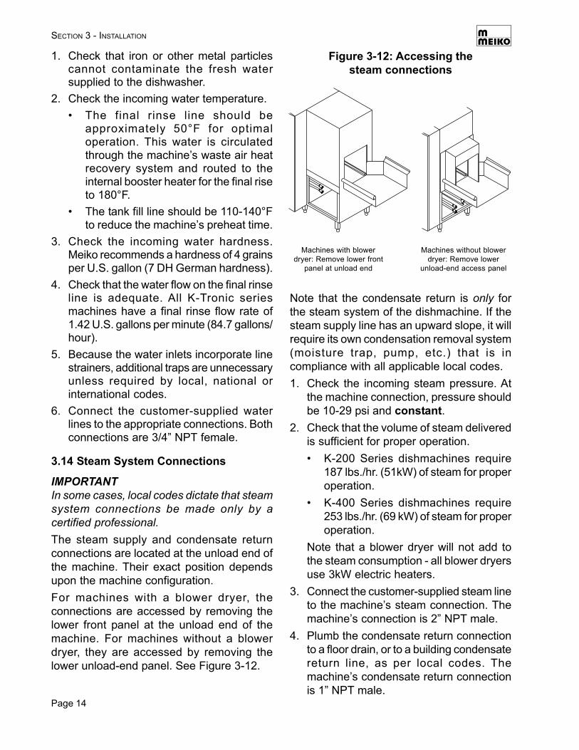
IMPORTANTIn some cases, local codes dictate that steamsystem connections be made only by acertified professional.The steam supply and condensate returnconnections are located at the unload end ofthe machine. Their exact position dependsupon the machine configuration.For machines with a blower dryer, theconnections are accessed by removing thelower front panel at the unload end of themachine. For machines without a blowerdryer, they are accessed by removing thelower unload-end panel. See Figure 3-12.
SECTION 3 - INSTALLATION
Note that the condensate return is only forthe steam system of the dishmachine. If thesteam supply line has an upward slope, it willrequire its own condensation removal system(moisture trap, pump, etc.) that is incompliance with all applicable local codes.1. Check the incoming steam pressure. At
the machine connection, pressure shouldbe 10-29 psi and constant.
2. Check that the volume of steam deliveredis sufficient for proper operation.• K-200 Series dishmachines require
187 lbs./hr. (51kW) of steam for properoperation.
• K-400 Series dishmachines require253 lbs./hr. (69 kW) of steam for properoperation.
Note that a blower dryer will not add tothe steam consumption - all blower dryersuse 3kW electric heaters.
3. Connect the customer-supplied steam lineto the machine’s steam connection. Themachine’s connection is 2” NPT male.
4. Plumb the condensate return connectionto a floor drain, or to a building condensatereturn line, as per local codes. Themachine’s condensate return connectionis 1” NPT male.
Figure 3-12: Accessing thesteam connections
Machines with blowerdryer: Remove lower front
panel at unload end
Machines without blowerdryer: Remove lower
unload-end access panel
Page 15
SECTION 3 - INSTALLATION
3.15 Drain Connection
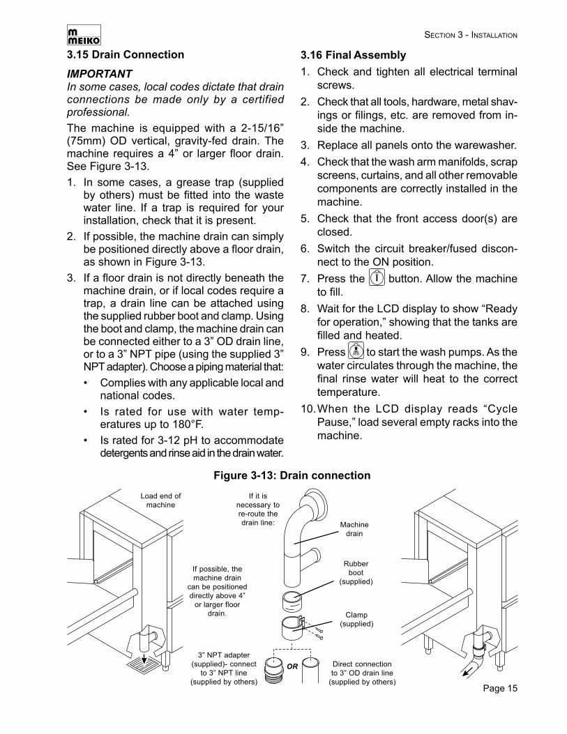
IMPORTANTIn some cases, local codes dictate that drainconnections be made only by a certifiedprofessional.The machine is equipped with a 2-15/16”(75mm) OD vertical, gravity-fed drain. Themachine requires a 4” or larger floor drain.See Figure 3-13.1. In some cases, a grease trap (supplied
by others) must be fitted into the wastewater line. If a trap is required for yourinstallation, check that it is present.
2. If possible, the machine drain can simplybe positioned directly above a floor drain,as shown in Figure 3-13.
3. If a floor drain is not directly beneath themachine drain, or if local codes require atrap, a drain line can be attached usingthe supplied rubber boot and clamp. Usingthe boot and clamp, the machine drain canbe connected either to a 3” OD drain line,or to a 3” NPT pipe (using the supplied 3”NPT adapter). Choose a piping material that:• Complies with any applicable local and
national codes.• Is rated for use with water temp-
eratures up to 180°F.• Is rated for 3-12 pH to accommodate
detergents and rinse aid in the drain water.
Figure 3-13: Drain connection
Load end ofmachine
If possible, themachine drain
can be positioneddirectly above 4”
or larger floordrain.
Machinedrain
If it isnecessary tore-route thedrain line:
Rubberboot
(supplied)
Clamp(supplied)
Direct connectionto 3” OD drain line
(supplied by others)
3” NPT adapter(supplied)- connect
to 3” NPT line(supplied by others)
3.16 Final Assembly1. Check and tighten all electrical terminal
screws.2. Check that all tools, hardware, metal shav-
ings or filings, etc. are removed from in-side the machine.
3. Replace all panels onto the warewasher.4. Check that the wash arm manifolds, scrap
screens, curtains, and all other removablecomponents are correctly installed in themachine.
5. Check that the front access door(s) areclosed.
6. Switch the circuit breaker/fused discon-nect to the ON position.
7. Press the button. Allow the machineto fill.
8. Wait for the LCD display to show “Readyfor operation,” showing that the tanks arefilled and heated.
9. Press to start the wash pumps. As thewater circulates through the machine, thefinal rinse water will heat to the correcttemperature.
10.When the LCD display reads “CyclePause,” load several empty racks into themachine.
Page 16
SECTION 3 - INSTALLATION
11. As the racks move through the machine,check that they move smoothly withoutbinding and that the wash and rinse armsactivate properly.
12.Prime the detergent and rinse aid pumpsaccording to the manufacturer ’sinstructions. The chemical installer shouldcheck for correct chemical concentrationat this time.
13.Allow all racks to exit the machine.14.Press to shut off the machine. Switch
the master circuit breaker/fuseddisconnect to the OFF position.
15.Move the drain handles to the DRAINOPEN position to empty the machine.
16.Remove the scrap screens, clean them ifthey are soiled, and allow them to air dry.
17.Remove the wash, rinse (and prewash ifso equipped) arm manifolds, clean themif necessary, and allow them to air dry.
18.Access the drain screens and clean themif necessary.
19.Access the two water inlets (see Figure3-11). Check the dirt traps and clean themif necessary.
20.Replace all components into the dish-washer. The machine is now ready forregular operation.
IMPORTANTThe appliance’s warranty is not valid until aMeiko Authorized Service Agent performs aPerformance and Installation Inspection.
Notes
________________________________________________________________________________
________________________________________________________________________________
________________________________________________________________________________
________________________________________________________________________________________________________________________________________________________________
________________________________________________________________________________________________________________________________________________________________
________________________________________________________________________________________________________________________________________________________________
________________________________________________________________________________________________________________________________________________________________
________________________________________________________________________________________________________________________________________________________________
________________________________________________________________________________________________________________________________________________________________
________________________________________________________________________________________________________________________________________________________________
________________________________________________________________________________________________________________________________________________________________
________________________________________________________________________________________________________________________________________________________________
________________________________________________________________________________________________________________________________________________________________

Page 17
SECTION 3 - INSTALLATION
Notes
________________________________________________________________________________
________________________________________________________________________________
________________________________________________________________________________
________________________________________________________________________________________________________________________________________________________________
________________________________________________________________________________________________________________________________________________________________
________________________________________________________________________________________________________________________________________________________________
________________________________________________________________________________________________________________________________________________________________
________________________________________________________________________________________________________________________________________________________________
________________________________________________________________________________________________________________________________________________________________
________________________________________________________________________________________________________________________________________________________________
________________________________________________________________________________________________________________________________________________________________
________________________________________________________________________________________________________________________________________________________________
________________________________________________________________________________________________________________________________________________________________
________________________________________________________________________________________________________________________________________________________________
________________________________________________________________________________________________________________________________________________________________
________________________________________________________________________________________________________________________________________________________________
________________________________________________________________________________________________________________________________________________________________
________________________________________________________________________________________________________________________________________________________________
________________________________________________________________________________________________________________________________________________________________
________________________________________________________________________________________________________________________________________________________________
________________________________________________________________________________________________________________________________________________________________
________________________________________________________________________________________________________________________________________________________________
________________________________________________________________________________
Page 18
4 OPERATION
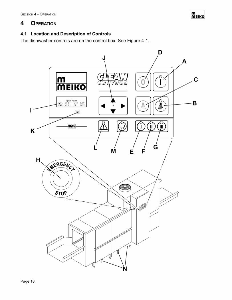
4.1 Location and Description of ControlsThe dishwasher controls are on the control box. See Figure 4-1.
SECTION 4 - OPERATION
Page 19
SECTION 4 - OPERATION
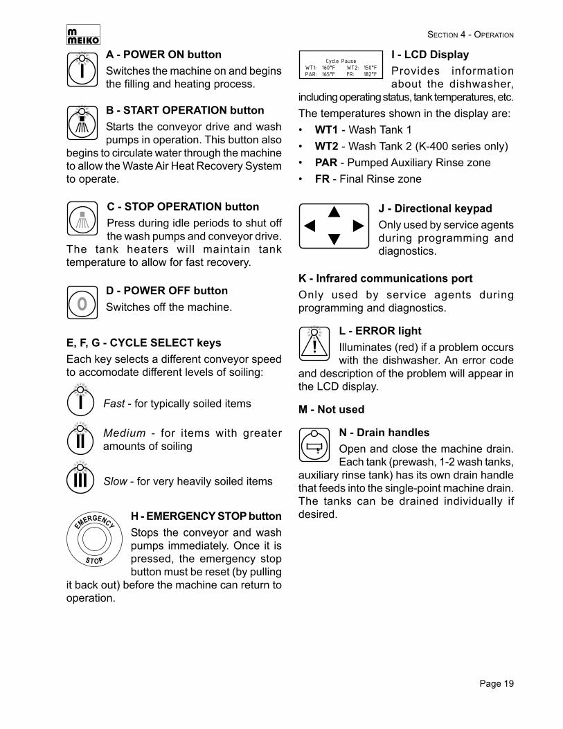
A - POWER ON buttonSwitches the machine on and beginsthe filling and heating process.
I - LCD DisplayProvides informationabout the dishwasher,
including operating status, tank temperatures, etc.The temperatures shown in the display are:• WT1 - Wash Tank 1• WT2 - Wash Tank 2 (K-400 series only)• PAR - Pumped Auxiliary Rinse zone• FR - Final Rinse zone
E, F, G - CYCLE SELECT keysEach key selects a different conveyor speedto accomodate different levels of soiling:
Medium - for items with greateramounts of soiling
Slow - for very heavily soiled items
B - START OPERATION buttonStarts the conveyor drive and washpumps in operation. This button also
begins to circulate water through the machineto allow the Waste Air Heat Recovery Systemto operate.
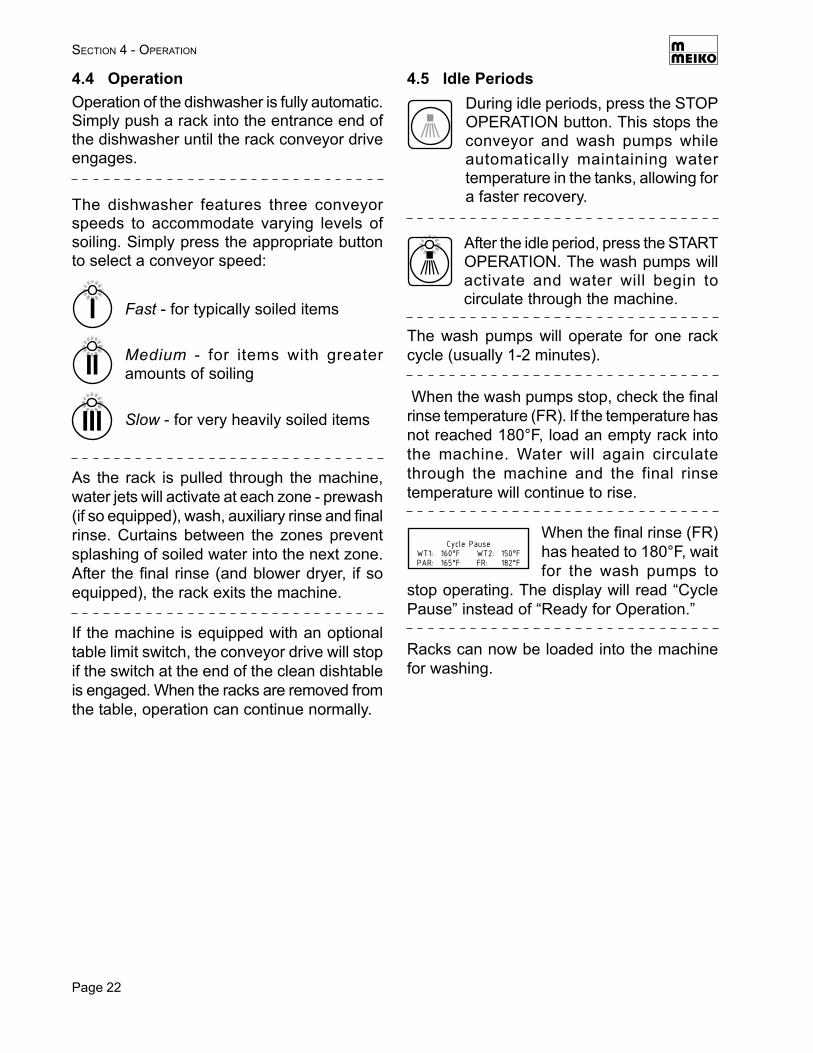
Fast - for typically soiled items
C - STOP OPERATION buttonPress during idle periods to shut offthe wash pumps and conveyor drive.
The tank heaters will maintain tanktemperature to allow for fast recovery.
D - POWER OFF buttonSwitches off the machine.
H - EMERGENCY STOP buttonStops the conveyor and washpumps immediately. Once it ispressed, the emergency stopbutton must be reset (by pulling
it back out) before the machine can return tooperation.
J - Directional keypadOnly used by service agentsduring programming anddiagnostics.
K - Infrared communications portOnly used by service agents duringprogramming and diagnostics.
L - ERROR lightIlluminates (red) if a problem occurswith the dishwasher. An error code
and description of the problem will appear inthe LCD display.
M - Not used
N - Drain handlesOpen and close the machine drain.Each tank (prewash, 1-2 wash tanks,
auxiliary rinse tank) has its own drain handlethat feeds into the single-point machine drain.The tanks can be drained individually ifdesired.
Page 20
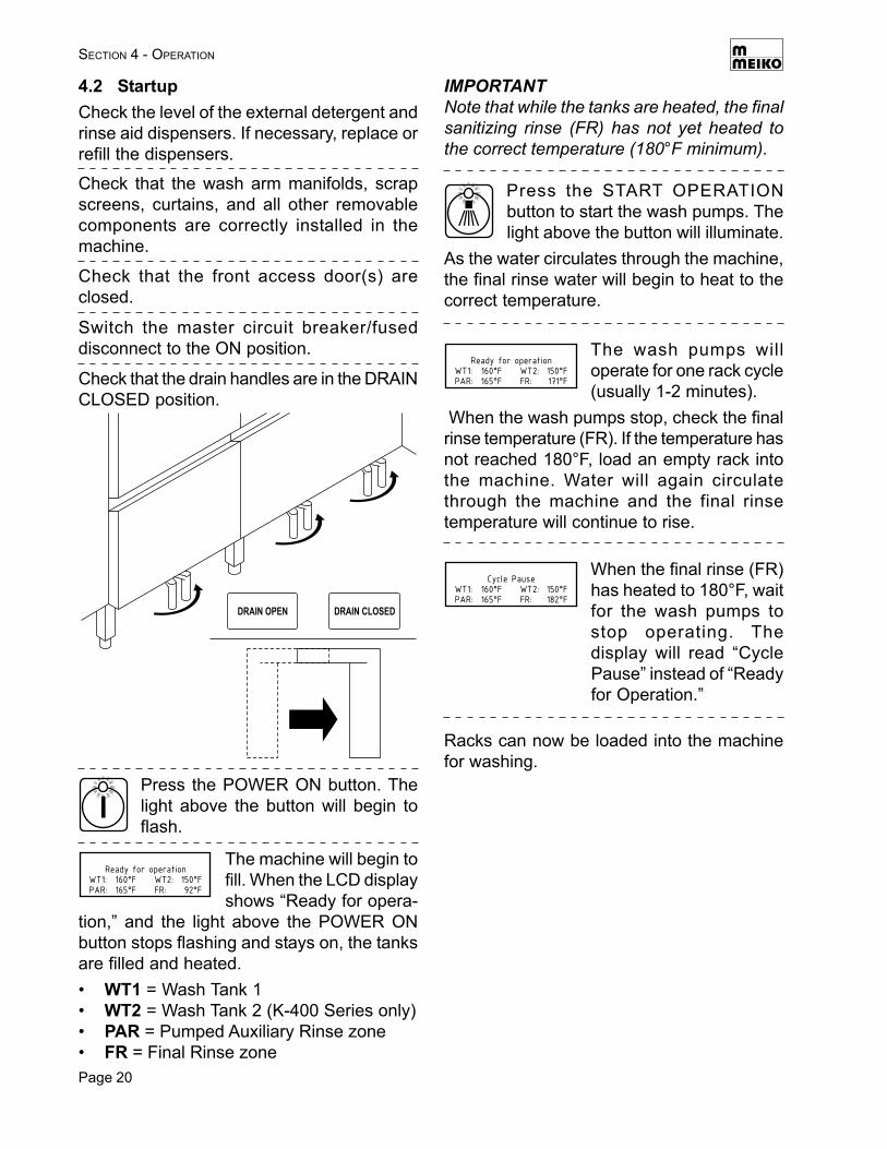
4.2 StartupCheck the level of the external detergent andrinse aid dispensers. If necessary, replace orrefill the dispensers.
Press the POWER ON button. Thelight above the button will begin toflash.
Check that the wash arm manifolds, scrapscreens, curtains, and all other removablecomponents are correctly installed in themachine.
Check that the front access door(s) areclosed.
Switch the master circuit breaker/fuseddisconnect to the ON position.
Check that the drain handles are in the DRAINCLOSED position.
SECTION 4 - OPERATION
The machine will begin tofill. When the LCD displayshows “Ready for opera-
tion,” and the light above the POWER ONbutton stops flashing and stays on, the tanksare filled and heated.• WT1 = Wash Tank 1• WT2 = Wash Tank 2 (K-400 Series only)• PAR = Pumped Auxiliary Rinse zone• FR = Final Rinse zone
Press the START OPERATIONbutton to start the wash pumps. Thelight above the button will illuminate.
As the water circulates through the machine,the final rinse water will begin to heat to thecorrect temperature.
When the final rinse (FR)has heated to 180°F, waitfor the wash pumps tostop operating. Thedisplay will read “CyclePause” instead of “Readyfor Operation.”
Racks can now be loaded into the machinefor washing.
The wash pumps willoperate for one rack cycle(usually 1-2 minutes).
When the wash pumps stop, check the finalrinse temperature (FR). If the temperature hasnot reached 180°F, load an empty rack intothe machine. Water will again circulatethrough the machine and the final rinsetemperature will continue to rise.
IMPORTANTNote that while the tanks are heated, the finalsanitizing rinse (FR) has not yet heated tothe correct temperature (180°F minimum).
Page 21
SECTION 4 - OPERATION
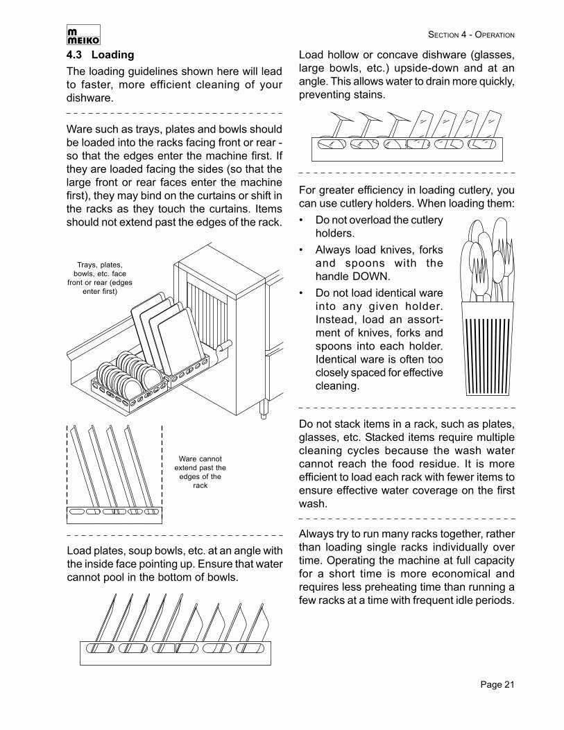
4.3 LoadingThe loading guidelines shown here will leadto faster, more efficient cleaning of yourdishware.
Ware such as trays, plates and bowls shouldbe loaded into the racks facing front or rear -so that the edges enter the machine first. Ifthey are loaded facing the sides (so that thelarge front or rear faces enter the machinefirst), they may bind on the curtains or shift inthe racks as they touch the curtains. Itemsshould not extend past the edges of the rack.
Load plates, soup bowls, etc. at an angle withthe inside face pointing up. Ensure that watercannot pool in the bottom of bowls.
Load hollow or concave dishware (glasses,large bowls, etc.) upside-down and at anangle. This allows water to drain more quickly,preventing stains.
For greater efficiency in loading cutlery, youcan use cutlery holders. When loading them:• Do not overload the cutlery
holders.• Always load knives, forks
and spoons with thehandle DOWN.
• Do not load identical wareinto any given holder.Instead, load an assort-ment of knives, forks andspoons into each holder.Identical ware is often tooclosely spaced for effectivecleaning.
Trays, plates,bowls, etc. face
front or rear (edgesenter first)
Ware cannotextend past the
edges of therack
Do not stack items in a rack, such as plates,glasses, etc. Stacked items require multiplecleaning cycles because the wash watercannot reach the food residue. It is moreefficient to load each rack with fewer items toensure effective water coverage on the firstwash.
Always try to run many racks together, ratherthan loading single racks individually overtime. Operating the machine at full capacityfor a short time is more economical andrequires less preheating time than running afew racks at a time with frequent idle periods.
Page 22
SECTION 4 - OPERATION
4.4 OperationOperation of the dishwasher is fully automatic.Simply push a rack into the entrance end ofthe dishwasher until the rack conveyor driveengages.
Fast - for typically soiled items
Medium - for items with greateramounts of soiling
Slow - for very heavily soiled items
As the rack is pulled through the machine,water jets will activate at each zone - prewash(if so equipped), wash, auxiliary rinse and finalrinse. Curtains between the zones preventsplashing of soiled water into the next zone.After the final rinse (and blower dryer, if soequipped), the rack exits the machine.
4.5 Idle Periods
After the idle period, press the STARTOPERATION. The wash pumps willactivate and water will begin tocirculate through the machine.
The wash pumps will operate for one rackcycle (usually 1-2 minutes).
The dishwasher features three conveyorspeeds to accommodate varying levels ofsoiling. Simply press the appropriate buttonto select a conveyor speed:
If the machine is equipped with an optionaltable limit switch, the conveyor drive will stopif the switch at the end of the clean dishtableis engaged. When the racks are removed fromthe table, operation can continue normally.
When the wash pumps stop, check the finalrinse temperature (FR). If the temperature hasnot reached 180°F, load an empty rack intothe machine. Water will again circulatethrough the machine and the final rinsetemperature will continue to rise.
When the final rinse (FR)has heated to 180°F, waitfor the wash pumps to
stop operating. The display will read “CyclePause” instead of “Ready for Operation.”
Racks can now be loaded into the machinefor washing.
During idle periods, press the STOPOPERATION button. This stops theconveyor and wash pumps whileautomatically maintaining watertemperature in the tanks, allowing fora faster recovery.
Page 23
Press the ERROR button toacknowledge the error. The flashinglight above the button should turn off.
WARNING!Before clearing a jam, ALWAYS pressthe POWER OFF button.
Open the front door(s) to access the jammedrack(s).
WARNING!When the front access doors areopened, steam will escape the interiorof the machine.
4.6 Clearing JamsUnder normal operating conditions, racks willnot jam as they move through the machine.However, improper loading or impropercurtain installation may cause a rack to jam.
SECTION 4 - OPERATION
If the conveyor jams, the ERRORlight will begin flashing and themachine will stop operating.
Press the POWER OFF button.
Open the front access door(s). Clean themachine as described in Section 5, Cleaning.Meiko recommends that the door of thedishwasher be left open overnight to allow itto air thoroughly.
WARNING!When the front access doors areopened, steam will escape the interiorof the machine.WARNING!For your safety, allow the interior of themachine to cool before cleaning.
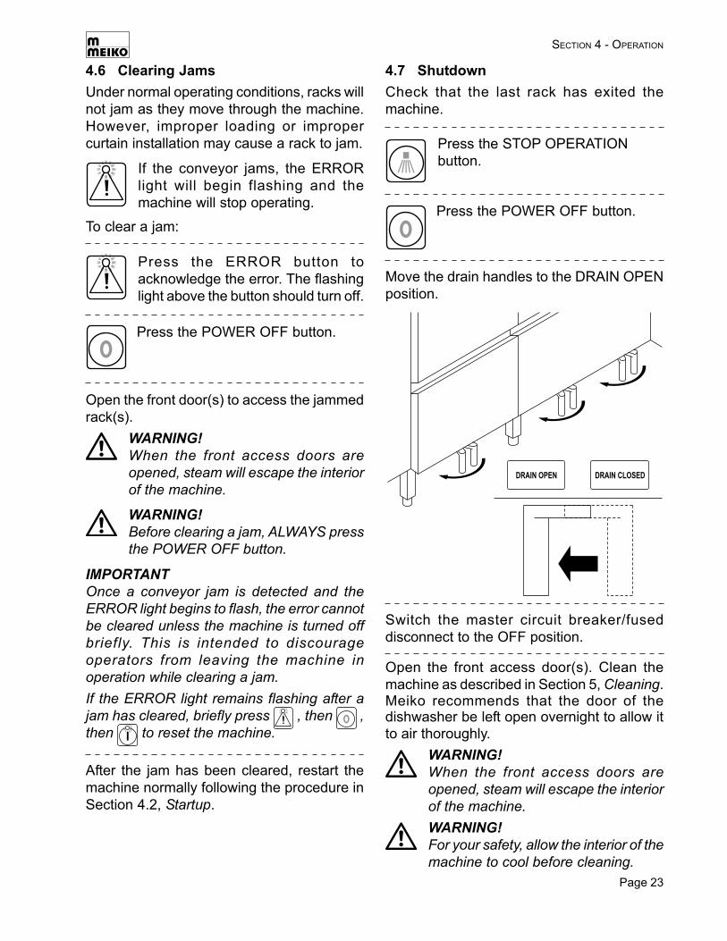
4.7 ShutdownCheck that the last rack has exited themachine.
Press the POWER OFF button.
Switch the master circuit breaker/fuseddisconnect to the OFF position.
Press the STOP OPERATIONbutton.
Move the drain handles to the DRAIN OPENposition.
To clear a jam:
IMPORTANTOnce a conveyor jam is detected and theERROR light begins to flash, the error cannotbe cleared unless the machine is turned offbriefly. This is intended to discourageoperators from leaving the machine inoperation while clearing a jam.If the ERROR light remains flashing after ajam has cleared, briefly press , then ,then to reset the machine.
After the jam has been cleared, restart themachine normally following the procedure inSection 4.2, Startup.
Page 24
5 CLEANING
WARNING!Before ANY cleaning, check that thecircuit breaker/fused disconnect is inthe OFF position and that the unit isswitched off.WARNING!When the front access doors areopened after operation, steam willescape the interior of the machine.WARNING!For your safety, allow the interior of themachine to cool before cleaning.
IMPORTANTThe headings Daily Cleaning and WeeklyCleaning in this section are generalrecommendations based on typical soiling.If soil beings to accumulate, the unit shouldbe cleaned more frequently. Extensive foodsoil deposits inside the machine work againstoptimal performance. Some items may notbe cleaned as effectively, resulting in the needfor either a slower conveyor speed or repeatwashing. In addition, heavy soiling in the washwater increases detergent consumption.
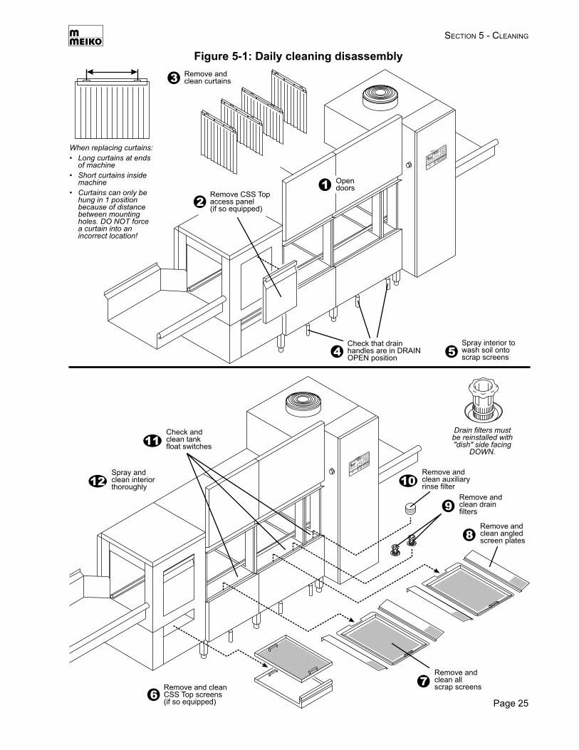
5.1 Daily Cleaning (or as required)Once per day, or as required, perform thefollowing steps:• Open the front access doors.• If the machine is equipped with a CSS Top
section, remove the front access panel asshown in Figure 5-1.
• Remove the curtains. Clean themthoroughly using a brush and warm water.
• Using a low-pressure hose or spraynozzle, spray the interior of the dishwasherto wash any soil and debris onto the scrapscreens.CAUTIONNever use a high-pressure water spraywhen cleaning the machine.
• If the machine is equipped with a CSS Topsection, remove the two-piece CSS Top
scrap screen as shown in Figure 5-1.Discard any food particles, scraps orbones. Then, clean the screen using abrush and warm water.
• Remove the scrap screens from theprewash, wash and rinse sections.Discard any food particles, scraps orbones. Then, clean the screens using abrush and warm water.
• Remove the angled screen plates on eachside of the prewash and wash tank scrapscreens. Clean the screen plates using abrush and warm water.
• Remove the drain filters. Clean themthoroughly using a brush and warm water.Be sure to use care to avoid damagingthe filter screens.
• Remove the auxiliary rinse tank filter.Clean it thoroughly using a brush andwarm water.
• Check that the tank float switchassemblies are clean.
• Check the interior of the machine for anyremaining food particles or debris.Thoroughly wash the interior with the low-pressure spray nozzle or hose. The tanksslope to the front for easier cleaning.
• Leave the doors of the machine open.Allow the interior of the machine, as wellas all scrap screens and baskets, to airdry thoroughly overnight.
• Reassemble all components into thedishwasher before operation.- When reinstalling the curtains, note
that each curtain can only be hung inone specific position because of thedistance between the mounting holes.DO NOT force a curtain into anincorrect location. See Figure 5-1.
- When reinstalling the drain filters, besure to replace them as shown withthe “dish” side facing down. See Figure5-1.
SECTION 5 - CLEANING
Page 25
SECTION 5 - CLEANING
Figure 5-1: Daily cleaning disassembly
Page 26
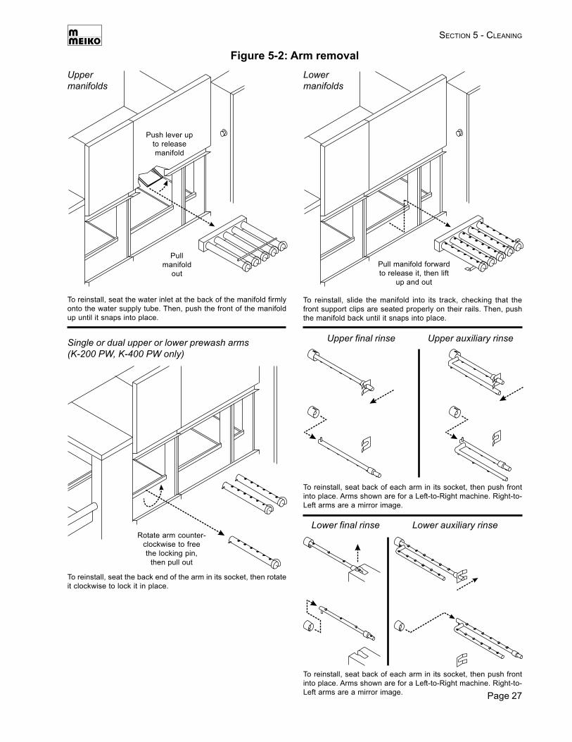
5.2 Weekly Cleaning (or as required)Once per week, or as required, perform thefollowing steps:• With the scrap screens removed from the
machine, remove the wash arm manifoldsSee Figure 5-2. If the machine is equippedwith a prewash section, the arms andmanifolds can also be removed at thistime.IMPORTANTUpper and lower manifolds are NOT in-terchangeable. However, some machinesmay have prewash manifolds that areidentical to the wash arm manifolds. Inthese machines, the manifolds are inter-changeable for easy replacement into themachine.
• Rotate each end cap counterclockwise toremove it from the end of its wash arm.The tether prevents the loss of the capduring cleaning.
• Clean the inside and outside of themanifolds, arms and end caps thoroughlywith a brush and warm water.
• Remove the upper and lower auxiliaryrinse and final rinse arms as shown inFigure 5-1.IMPORTANTUpper and lower rinse arms are NOT in-terchangeable. However, the arms aredesigned so that they cannot be rein-stalled in the wrong location.
• Clean the inside and outside of the armsthoroughly using a brush and warm water.
• Allow all arms, manifolds and end caps toair dry thoroughly overnight.
• Reassemble all components into the dish-washer before operation.
5.3 Exterior cleaning (as required)CAUTIONWhen cleaning the exterior of the dishwasher,be sure to follow these guidelines:• A commercial stainless steel cleaner can
be used on exterior body panels. Followthe manufacturer’s directions.
• Meiko strongly recommends usingdetergent, instead of a stainless steelcleaner, when cleaning the control panelof the unit. These chemicals can damagethe gauges, lights and labels.
• Never use abrasive cleaners or pads whencleaning the exterior of the dishwasher.These can scratch the surface of the unit.
WARNING!Ensure that detergents and stainlesssteel cleaners are kept out of theinterior of the dishwasher. If the interiorof the unit requires cleaning, refer tothe deliming procedures (Section 5.4).
SECTION 5 - CLEANING
Page 27
Push lever upto releasemanifold
Pullmanifold
out
Uppermanifolds
Pull manifold forwardto release it, then lift
up and out
Lowermanifolds
Single or dual upper or lower prewash arms(K-200 PW, K-400 PW only)
Rotate arm counter-clockwise to freethe locking pin,
then pull out
To reinstall, seat the water inlet at the back of the manifold firmlyonto the water supply tube. Then, push the front of the manifoldup until it snaps into place.
To reinstall, slide the manifold into its track, checking that thefront support clips are seated properly on their rails. Then, pushthe manifold back until it snaps into place.
To reinstall, seat the back end of the arm in its socket, then rotateit clockwise to lock it in place.
Lower final rinse
To reinstall, seat back of each arm in its socket, then push frontinto place. Arms shown are for a Left-to-Right machine. Right-to-Left arms are a mirror image.
Figure 5-2: Arm removal
Lower auxiliary rinse
To reinstall, seat back of each arm in its socket, then push frontinto place. Arms shown are for a Left-to-Right machine. Right-to-Left arms are a mirror image.
Upper final rinse Upper auxiliary rinse
SECTION 5 - CLEANING
Page 28
5.4 Deliming (as required)Lime scale deposits will occur over time onthe interior of the dishwasher if it is operatedusing a hard water supply. Meiko recommendsa hardness of 4 grains per U.S. gallon (7 DHGerman hardness).A deliming or de-scaling process can be usedto remove these deposits, as well as anyaccumulated food residue.When deliming the interior, be sure to followthese guidelines:• Use deliming agents designed for use with
commercial dishwashers.• Follow the instructions for the deliming
agent that is used.• Start the machine as described in Sec-
tion 4, Operation.• After the deliming procedure, continue to
run the dishwasher for at least 10 min-utes to rinse the interior thoroughly. Cycleempty racks through the machine as nec-essary to keep the pumps in operation.
• Press to shut off the machine. Switchthe circuit breaker/fused disconnect to theOFF position.
• Move the drain handles to the DRAINOPEN position.
• Remove all scrap screens, wash armmanifolds, prewash arms (if so equipped),auxiliary rinse and final rinse arms. Cleanthem as described in Sections 5.1 and 5.2of this Manual.
• Inspect the interior for any remainingdeliming agent residue. If residue ispresent, remove it using a soft cloth andhot water.
• Thoroughly flush the interior of thedishwasher using warm water from a low-pressure hose or spray nozzle.
CAUTIONNever use a high-pressure water spraywhen cleaning the machine.
• Leave the doors of the machine open toallow the interior to air dry thoroughly.
• Reassemble all components into the dish-washer before operation.
WARNING!Ensure that ALL residue of thedeliming agent is removed. Residuefrom the agent can:- Pose a health hazard;- Damage seals and plastic compo-
nents inside the dishwasher.
SECTION 5 - CLEANING
Page 29
SECTION 6 - TROUBLESHOOTING
6 TROUBLESHOOTING
If the dishwasher encounters a problem, check this Troubleshooting Guide. Some simpleproblems can be quickly resolved, allowing the dishwasher to be returned to operation fasterthan placing a service call.
Problem ActionMachine does not fill • Check that all drain filters are correctly installed and that the drain handles
are in the DRAIN CLOSED position.• Check that the water supply is turned on.• Check the dirt trap(s) in the water inlet(s) and clean them if necessary.• Check the float switches in the tank(s). If the switch(es) are dirty or coated
with chemicals or lime deposits, they may not function correctly. If they aredirty, clean or delime the interior.
Final rinse does notactivate
• Check that the water supply is turned on.• Check the line strainer in the cold (rinse) water inlet and clean it if necessary.• Check for lime scale deposits on the final rinse arms. These deposits can
clog the final rinse nozzles. Delime if necessary.
Steam escapes themachine during operation
All rack conveyor dishwashers release some steam at the ends of the machine.However, if steam is excessive, check the following:• Check that the curtains are correctly installed.• Check the final rinse temperature on the digital display (FR) to ensure that
it is operating at the correct temperature.
Water leaks around frontaccess door seamsduring operation
• Check that the end caps are correctly installed at the end of all prewashand wash arms.
• Check that all auxiliary rinse and final rinse arms are correctly installed.
Stripes/smears on ware • Check that the curtains are installed properly.• Check that the ware is correctly loaded. Refer to the Operation section of
this Manual.• Check for correct detergent and rinse aid concentration.• Check for excessive mineral content in the water supply. Meiko recommends
a hardness of 4 grains per U.S. gallon.
Foaming in the wash tank • Check that commercial (not domestic) detergents and rinse aids are beingused.
• Check for correct detergent and rinse aid concentration.• Check that heavily soiled ware is being correctly pre-scrapped. Excessive
amounts of grease or soiling in the wash tank can cause foaming.• Check that the tank temperatures shown on the digital display are correct.
WT1 = Wash Tank 1; WT2 = Wash Tank 2; PAR = Pumped Auxiliary Rinsezone; FR = Final Rinse zone.
Contact your Meiko Authorized Service Agent if you cannot correct the problem.An Authorized Service Agency Listing was supplied with your dishwasher. If you do nothave the listing, call 1-800-868-3840 for assistance, or visit Meiko’s website at www.meiko.us.
Tank temperatures are toolow
• Check that the curtains are correctly installed.• Check that the tank float switch assemblies are clean.• Check the steam supply (if so equipped). The machine is set up to operate
correctly with the steam volume and pressure that are present duringinstallation. Low pressure and/or volume may affect performance.

Page 30
Notes
________________________________________________________________________________
________________________________________________________________________________
________________________________________________________________________________
________________________________________________________________________________________________________________________________________________________________
________________________________________________________________________________________________________________________________________________________________
________________________________________________________________________________________________________________________________________________________________
________________________________________________________________________________________________________________________________________________________________
________________________________________________________________________________________________________________________________________________________________
________________________________________________________________________________________________________________________________________________________________
________________________________________________________________________________________________________________________________________________________________
________________________________________________________________________________________________________________________________________________________________
________________________________________________________________________________________________________________________________________________________________
________________________________________________________________________________________________________________________________________________________________
________________________________________________________________________________________________________________________________________________________________
________________________________________________________________________________________________________________________________________________________________
________________________________________________________________________________________________________________________________________________________________
________________________________________________________________________________________________________________________________________________________________
________________________________________________________________________________________________________________________________________________________________
________________________________________________________________________________________________________________________________________________________________
________________________________________________________________________________________________________________________________________________________________
________________________________________________________________________________________________________________________________________________________________
________________________________________________________________________________________________________________________________________________________________
________________________________________________________________________________

Page 31
Notes
________________________________________________________________________________
________________________________________________________________________________
________________________________________________________________________________
________________________________________________________________________________________________________________________________________________________________
________________________________________________________________________________________________________________________________________________________________
________________________________________________________________________________________________________________________________________________________________
________________________________________________________________________________________________________________________________________________________________
________________________________________________________________________________________________________________________________________________________________
________________________________________________________________________________________________________________________________________________________________
________________________________________________________________________________________________________________________________________________________________
________________________________________________________________________________________________________________________________________________________________
________________________________________________________________________________________________________________________________________________________________
________________________________________________________________________________________________________________________________________________________________
________________________________________________________________________________________________________________________________________________________________
________________________________________________________________________________________________________________________________________________________________
________________________________________________________________________________________________________________________________________________________________
________________________________________________________________________________________________________________________________________________________________
________________________________________________________________________________________________________________________________________________________________
________________________________________________________________________________________________________________________________________________________________
________________________________________________________________________________________________________________________________________________________________
________________________________________________________________________________________________________________________________________________________________
________________________________________________________________________________________________________________________________________________________________
________________________________________________________________________________

Meiko917 Airpark Center DriveNashville, TN 37217Phone: (615) 399-6600(800) 55-MEIKOFax: (615) 399-6620
If you need service...
Meiko warewashers are designed for solid reliability as much as foroutstanding ware-cleaning ability. With proper care, your warewashershould provide years of trouble-free operation.If service is necessary, contact your local Meiko Authorized ServiceAgent. With factory training, OEM parts and direct support from thefactory, Meiko’s nationwide service network is highly qualified to quicklyrestore your warewasher to regular operation.An Authorized Service Agency Listing is supplied with this Manual.If you do not have the listing, call 1-800-868-3840 for assistance.