Embed Size (px)
Citation preview
High Throughput AES Encryption Algorithm Implementation on FPGA
Gurmail Singh, Rajesh Mehra
Student of ECE Department, NITTTR,Chandigarh
Faculty of ECE Department, NITTTR,Chandigarh
Abstract
This paper describes an efficient hardware
realization of the Advanced Encryption Standard
(AES) algorithm using FPGA. The AES also known as
the Rijndael algorithm was selected as a Standard on
October 2, 2000 by National Institute of Standards and
Technology (NIST). Encryption algorithms are used to
ensure security of transmission channels.We use AES
128- bit block size and 128-bit cipher key for the
implementation on Xilinx Virtex 5 FPGA. Xilinx ISETM
12.4 design tool is used for synthesis of the design.
The design is coded using Very High Speed
Integrated Circuit Hardware Description
Language(VHDL). In our fully pipelined design, the
operational frequency can be upto 347.6MHz and the
throughput can be upto 44.5Gbits/s. The proposed
fully pipelined AES realization achieves high
throughput requirements and can be used for
cryptology applications such as data security.
Key words: Fully pipelined, AES, FPGA
implementation.
1.INTRODUCTION
1.1AES
This AES algorithm was developed by two Belgian
scientists Vincent Rijmen and Joan Daemen, whose
surnames are reflected in the cipher's name. The other
competing algorithms were Mars, RC6, Serpent and
Two-fish. The Predecessor to the AES was Data
Encryption Standard (DES) which is considered to be
insecure because of its vulnerability to brute force
attacks. DES was a standard from 1977 and stayed
until the mid 1990’s. However, by the mid 1990’s, it
was clear that the DES’s 56-bit key was no longer big
enough to prevent attacks mounted on contemporary
computers, which were thousands of times more
powerful than those available when the DES was
standardized.
Encryption is the translation of data to a secret code.
Apart from its uses in Military and Government to
facilitate secret communication, Encryption is used in
protecting many kinds of civilian systems such as
Internet E-commerce, Mobile networks, Automatic
teller machine transactions and many more. The
Encrypted data can only be deciphered if one has the
password or the Key.
An encryption algorithm provides Confidentiality,
Authentication, Integrity and Non-repudiation.
Encryption algorithms are broadly classified as
Symmetric or Asymmetric algorithms based on the
kind of Keys used. Symmetric algorithms have one
key. The key needs to be private or secret to maintain
confidentiality. So both the sender who encrypts the
information and the receiver who decrypts the
information needs to have the same key. Asymmetric
algorithms have two keys. One is the public key and
the other is the private key. The data is encrypted by
using the public key and is decrypted by the receiver
using the private key. Asymmetric algorithms are
computationally more intensive as compared to the
Symmetric algorithms. Advanced Encryption Standard
based on the Rijndael algorithm is one such Symmetric
algorithm for Encryption.
1.2.BASICS OF AES The byte value in AES is represented as a set of bits (0
or 1) and is represented as the collection of bits
separated by comma as {b7, b6, b5, b4, b3, b2, b1, b0}.
These bytes are interpreted as finite field elements
using polynomial representation as
Gurmail Singh et al, Int. J. Comp. Tech. Appl., Vol 2 (6), 1993-1996
IJCTA | NOV-DEC 2011 Available [email protected]
1993
ISSN:2229-6093
b7x7 + b6x
6+ b5x
5+ b4x
4 + b3x
3+ b2x
2+ b1x+ b0 (1)
All the operations performed in AES are modulo-2
operations. These Operations are not as the same
operations used in general Number System.
In modulo-2 additions, two elements are added by
adding the coefficients of the corresponding powers in
the polynomial. The addition operation here is the
XOR operation denoted by⊕. Subtraction of the
polynomials is exactly the same as addition. Addition
of 2 bytes {a7a6a5a4a3a2a1a0} and {b7b6b5b4b3b2b1b0} is
{c7c6c5c4c3c2c1c0} where each ci =ai⊕bi.
For example
If A = (179)10 and B = (90)10 then
A+B= (179)10 ⊕ (90)10 = (233)10
A-B= (233)10.
This can be represented in different forms as shown
below :
( x7 + x
5 + x
4 + x + 1) ⊕ ( x
6 + x
4+ x
3+ x) = x
7 + x
6 +
x5 + x
3+ 1 (2)
Multiplication denoted by • is the multiplication of the
polynomial over an irreducible polynomial of degree 8.
For the AES algorithm this irreducible polynomial is
m(x) = x8 + x
4+ x
3+ x+1 (3)
Equation (3) can be also be written as {100011011}2 or
{011b}h in binary and Hexadecimal format
respectively.
For example {72} • {18} = {dc}
(x6 + x
5 + x
4 + x) (x
4 + x
3) =x
10 + x
9 + x
8 + x
5
+x9+ x
8 + x
7 + x
4
= x10
+ x7 + x
5 + x
4 (4)
x10
+ x7 + x
5 + x
4 modulo (x
8 + x
4+ x
3+ x+1)
=x7 + x
6 +x
4 + x
3 + x
2 (5)
2.AES ENCRYPTION ALGORITHM
The AES algorithm operates on 128 bits of data and
generates 128 bits of output. The length of the key used
to encrypt this input data can be 128, 192 or 256 bits.
This paper will deal with only the 128 bits of key. As
this is private key cipher it uses just one key of 128 bits
which is used both for Encryption and Decryption. The
AES algorithm basically consists of four byte oriented
transformations. These transformations are:
a) Byte substitution using S-box table(S-box)
b)Shifting rows of the state array (Row transformation)
c) Mixing the data within each column of the state
array(Mixing columns)
d) Adding a round key to the state(Add round key)
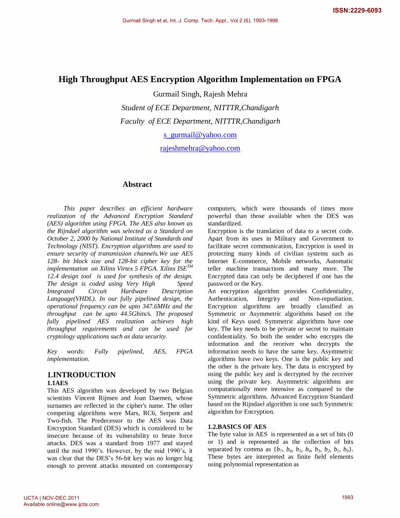
The set of these four transformations is also called as a
round transformation. Round Transformation is a set of
operations which consists of the four transformations.
It accepts the current State and the current key as the
inputs and returns a State. Each one of the iteration
consists of these steps with the exception of first and
the last iterations. The first iteration only consists of
the Add round key. The 128 bits key is added to the
128 bits of data which results in 128 bits of state is
used for the next iteration. The last iteration is more or
less similar to the other iterations except it does not
have the Column mixing. The Add round key adds the
key to the already processed data.The AES algorithm
can also be described by the flow chart shown below:
Figure 1: AES Algorithm Flowchart
2.1.BYTE SUBSTITUTION USING S-BOX
TABLE
S- box or the Sub bytes transformation is the only non-
linear transformation. S-box transformation mainly
consists of two sub steps:
a) Multiplicative inverse of each and every byte over
the irreducible polynomial. (x8 + x
4+ x
3+x+1)
b) Then apply affine transformation, which is defined
by:
(6)
2.2.ROW TRANSFORMATION
Row transformation essentially consists of shifting the
bytes in the row.
Gurmail Singh et al, Int. J. Comp. Tech. Appl., Vol 2 (6), 1993-1996
IJCTA | NOV-DEC 2011 Available [email protected]
1994
ISSN:2229-6093
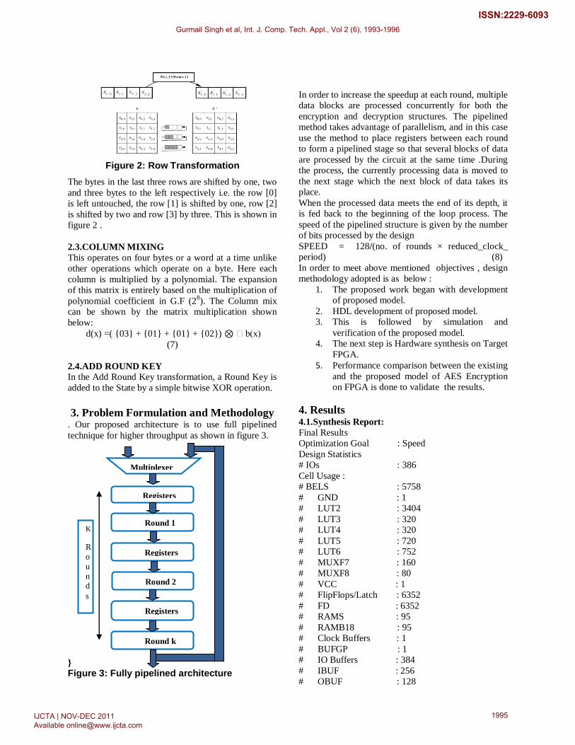
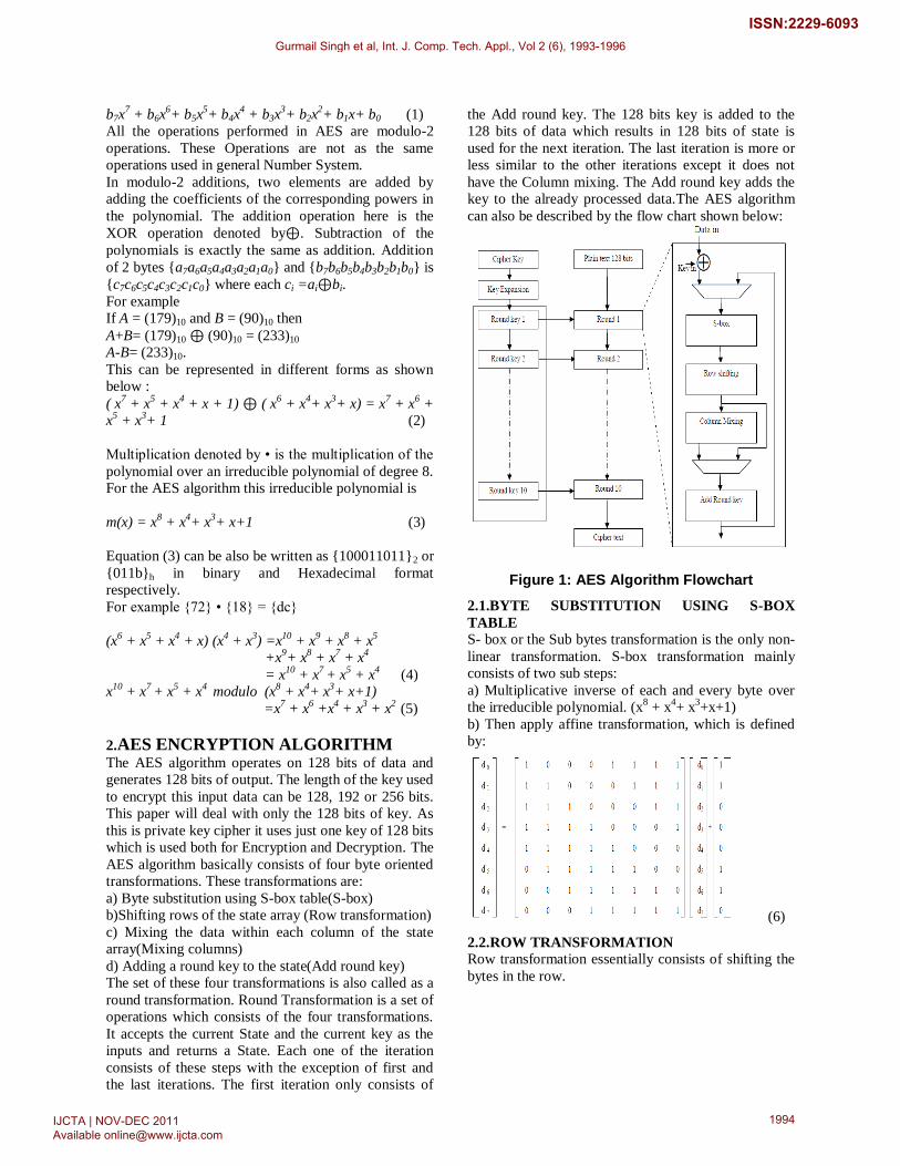
Figure 2: Row Transformation
The bytes in the last three rows are shifted by one, two
and three bytes to the left respectively i.e. the row [0]
is left untouched, the row [1] is shifted by one, row [2]
is shifted by two and row [3] by three. This is shown in
figure 2 .
2.3.COLUMN MIXING
This operates on four bytes or a word at a time unlike
other operations which operate on a byte. Here each
column is multiplied by a polynomial. The expansion
of this matrix is entirely based on the multiplication of
polynomial coefficient in G.F (28). The Column mix
can be shown by the matrix multiplication shown
below:
d(x) =( {03} + {01} + {01} + {02}) ⊗ b(x)
(7)
2.4.ADD ROUND KEY
In the Add Round Key transformation, a Round Key is
added to the State by a simple bitwise XOR operation.
3. Problem Formulation and Methodology
. Our proposed architecture is to use full pipelined
technique for higher throughput as shown in figure 3.
}
Figure 3: Fully pipelined architecture
In order to increase the speedup at each round, multiple
data blocks are processed concurrently for both the
encryption and decryption structures. The pipelined
method takes advantage of parallelism, and in this case
use the method to place registers between each round
to form a pipelined stage so that several blocks of data
are processed by the circuit at the same time .During
the process, the currently processing data is moved to
the next stage which the next block of data takes its
place.
When the processed data meets the end of its depth, it
is fed back to the beginning of the loop process. The
speed of the pipelined structure is given by the number
of bits processed by the design
SPEED = 128/(no. of rounds × reduced_clock_
period) (8)
In order to meet above mentioned objectives , design
methodology adopted is as below :
1. The proposed work began with development
of proposed model.
2. HDL development of proposed model.
3. This is followed by simulation and
verification of the proposed model.
4. The next step is Hardware synthesis on Target
FPGA.
5. Performance comparison between the existing
and the proposed model of AES Encryption
on FPGA is done to validate the results.
4. Results 4.1.Synthesis Report:
Final Results
Optimization Goal : Speed
Design Statistics
# IOs : 386
Cell Usage :
# BELS : 5758
# GND : 1
# LUT2 : 3404
# LUT3 : 320
# LUT4 : 320
# LUT5 : 720
# LUT6 : 752
# MUXF7 : 160
# MUXF8 : 80
# VCC : 1
# FlipFlops/Latch : 6352
# FD : 6352
# RAMS : 95
# RAMB18 : 95
# Clock Buffers : 1
# BUFGP : 1
# IO Buffers : 384
# IBUF : 256
# OBUF : 128
Registers
Round 1
Registers
Round 2
Registers
Round k
Multiplexer
rrrrrrrrr
K
R
o
u
nd
s
Gurmail Singh et al, Int. J. Comp. Tech. Appl., Vol 2 (6), 1993-1996
IJCTA | NOV-DEC 2011 Available [email protected]
1995
ISSN:2229-6093

Device Utilization Summary (estimated values)
Logic Utilization Used Available Utilization
Number of Slice
Registers 6352 51840 12%
Number of Slice LUTs 5516 51840 10%
Number of fully used
LUT-FF pairs 4854 7014 69%
Number of bonded
IOBs 385 440 87%
Number of Block
RAM/FIFO 48 96 50%
Number of
BUFG/BUFGCTRLs 1 32 3%
Timing Summary:
---------------
Speed Grade: -3
Minimum period: 2.877ns (Maximum Frequency:
347.608MHz)
Minimum input arrival time before clock: 1.402ns
Maximum output required time after clock: 2.775ns
Maximum combinational path delay: No path found
Total memory usage is 244764 kilobytes.
4.2.Simulation Waveform:
5. Conclusion & Future Scope
Proposed work includes full pipelined architecture for
AES encryption so that the throughput is increased. In
our fully pipelined design, we achieved the operational
frequency upto 347.6MHz and the throughput upto
44.5Gbits/s. The Encryption and the Decryption
modules can be combined together in a single module.
Further optimization or new architectures for S-box
and Inverse Mix Columns can also improve the
performance. Support for 192 and 256 bit key can also
be considered for the future improvements of this
design. References
[1]“Advanced Encryption Standard”Federal Information
Processing Standards Publication 197,Nov.2001 , “
http://csrc.nist.gov/publications/fips/ fips197/fips-197.pdf ”.
[2]Daemen .J and Rijmen .V ,The Design of Rijndael AES –
THE ADVANCED ENCRYPTION STANDARD, pages.2 -
5 , Springer, 2002.
[3] Kimmo U. Järvinen , Matti T. Tommiska , Jorma O.
Skyttä, “A fully pipelined memoryless 17.8 Gbps AES-128
encryptor,” Proceedings of the 2003 ACM/SIGDA Eleventh
International symposium on Field programmable gate arrays,
pp.207 – 215, February, 2003.
[4] H. Li, Z. Friggstad, “An Efficient Architecture for the
AES Mix Columns Operation,” International Symposium on
Circuits and Systems, pp.4637-4640 , IEEE 2005.
[5] Nadia Nedjah and Luiza de Macedo Mourelle ,
“Embedded Hardware for Cryptosystems ,” Journal of
Systems Architecture,” Vol.53, Issues.2-3, , pp.69-71,
February-March 2007.
[6] K.Gaj and P. Chodowiec, “Comparison of the Hardware
Performance of the AES Candidates using Reconfigurable
Hardware,” Proceedings of 3rd Advanced Encryption
Standard Conference (AES3), 13-14 April 2000.
[7]Chih-Peng Fan and Jun-Kui Hwang, “FPGA
Implementation of High Throughput Sequential and Fully
Pipelined AES Algorithm” International Journal of Electrical
Engineering ,Vol. 15, No.06, pp.447-455, 2008.
[8]Sujatha Hiremath and M.S.Suma, “Advanced Encryption
Standard Implemented on FPGA” Second International
Conference on Computer and Electrical Engineering, pp.656-
60, IEEE 2009.
Gurmail Singh et al, Int. J. Comp. Tech. Appl., Vol 2 (6), 1993-1996
IJCTA | NOV-DEC 2011 Available [email protected]
1996
ISSN:2229-6093