Embed Size (px)
Citation preview
High-voltage electrical survey advancement
Daniel A. Ninedorf
Ox Creek Energy Associates, Inc.
PO Box 600, Montello, WI 53949-0600
Tel: 800-531-6232 Fax: (608)589-5509
Email: [email protected] Web: www.specialcamera.com
ABSTRACT
Technology miniaturization has made new advancements in high voltage electrical surveying possible. A solar-
blind ultraviolet image overlaid onto infrared, combined with a solar -blind ultravi olet image and then overlaid onto
color visible in the same camera with a weight of 6 pounds provides the comparison images and portability to allow
an operator to do on-the-spot analysis and repair priority assignment. The UV-VIS image provides the quick est
location and identification. The UV -IR image allows analysis to determine if there is damage and the severity. This
can be accomplished in just seconds thru menu selection: before it required two separate cameras. This presentation
will provide exampl es of different images and analysis, with operating time from hand -held, laboratory, vehicle and
aerial camera mounts.
Keywords: Corona, Infrared, High Voltage, Cameras, Substations, Transmission Line, Inspection
INTRODUCTION
In 1997 Mr. Roel Stolper
1.
a research engineer at the CSIR in M&M Tek division began looking for a daylight
corona camera to make the inspection of electric utility transmission lines from a helicopter possible and safer.
2.
Up
to this time corona inspection were accomplished in l ow-light environments using cameras developed by Roel. In
2000 the daylight corona camera began field testing and operation evolving with additional capabilities to colorize
the corona to contrast with the background, to filter the corona to remove “noise” ultraviolet light, and to integrate
the corona image to be able to distinguish smaller quantities.
Concurrent with the development of corona cameras, but in more widespread use were infrared cameras, these
cameras were also evolving and becoming smaller, the technology of measurement was also advancing, taking into
account background temperatures, distance to item being observed, and the emissivity of highly conductive metals
such as aluminum and the effect of temperature on emissivity.
High voltage electrical equipment is typically made of highly conductive aluminum alloys which are the most
difficult to accurately measure temperature using infrared. In research facilities and in manufacturing facilities
where it is desirable to measure the temperature of aluminum reliably or on predictive maintenance routes the
infrared technicians apply a short piece of black electrical tape to keep the emissivity constant at 0.95 which may
also be accomplished with some powders and paints having specific emissivity’s . The energized state of the items
observed make the emissivity correction steps impossible except in the lab, thus comparison between phases is a
good means and the fact that if the device is extremely hot it doesn’t matter what the emissivity is, imminent re pairs
are required.
When the corona cameras were developed it was expected by infrared camera users that the evolution would have
infrared and corona cameras be in the same camera case. Some infrared techs have resisted incorporating the two
technologies, other manufacturers misleading marketing may lead this resistance. The understanding of what is seen
with an infrared camera under these conditions is still evolving and the corona technology is gaining understanding
also. The combination of these technolo gies, concurrent images with infrared and corona create a new level of
understanding and an opportunity to reduce inspection costs by reducing survey time and potentially the equipment
costs and increase the information by looking concurrently at the objec ts.
The evolution includes accessories such as low power, light -weight, daylight viewable, high -resolution LCD
displays that enlarge the image showing as much detail as possible and the “zoom” capability of the display and
camera. In addition the ergonomic s of portable cameras require light -weight high power capacity batteries, image
and video recording with audio clips or detailed audio descriptions, Global Position Sensing (GPS) built -in to record
the camera location at the time the image was taken, and c ontinual review of the technologies available to increase
the operators knowledge of the weather and other contributing factors to when corona will occur.
The following pictures show a distribution voltage electrical inspection:
Figures 1 is an infrared image with corona overlaid, which does show added heat where the corona is, but not
enough to attract the attention of most camera operators due to the solar heating on the many items on the pole.
Figure 2 is a visible image wit h corona overlaid, which shows the corona activity (red color) more distinctly.
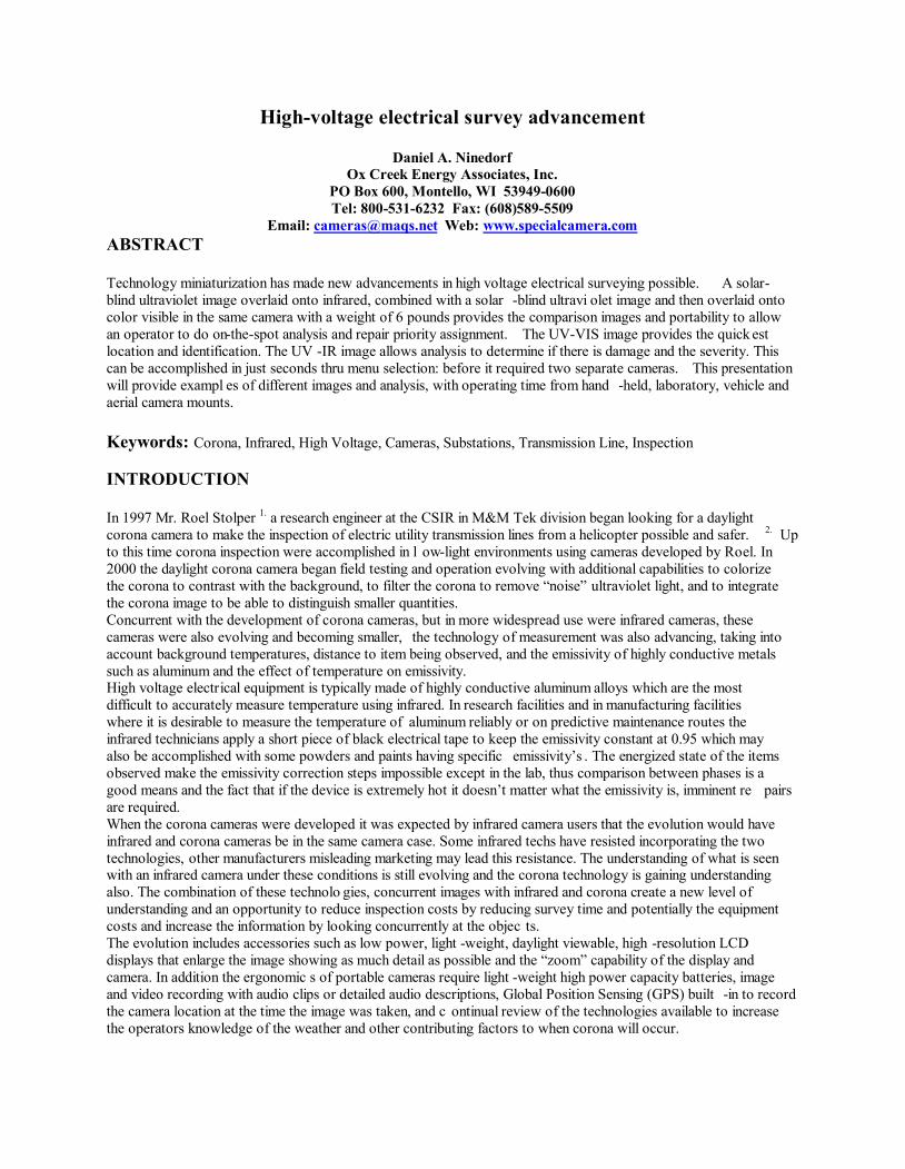
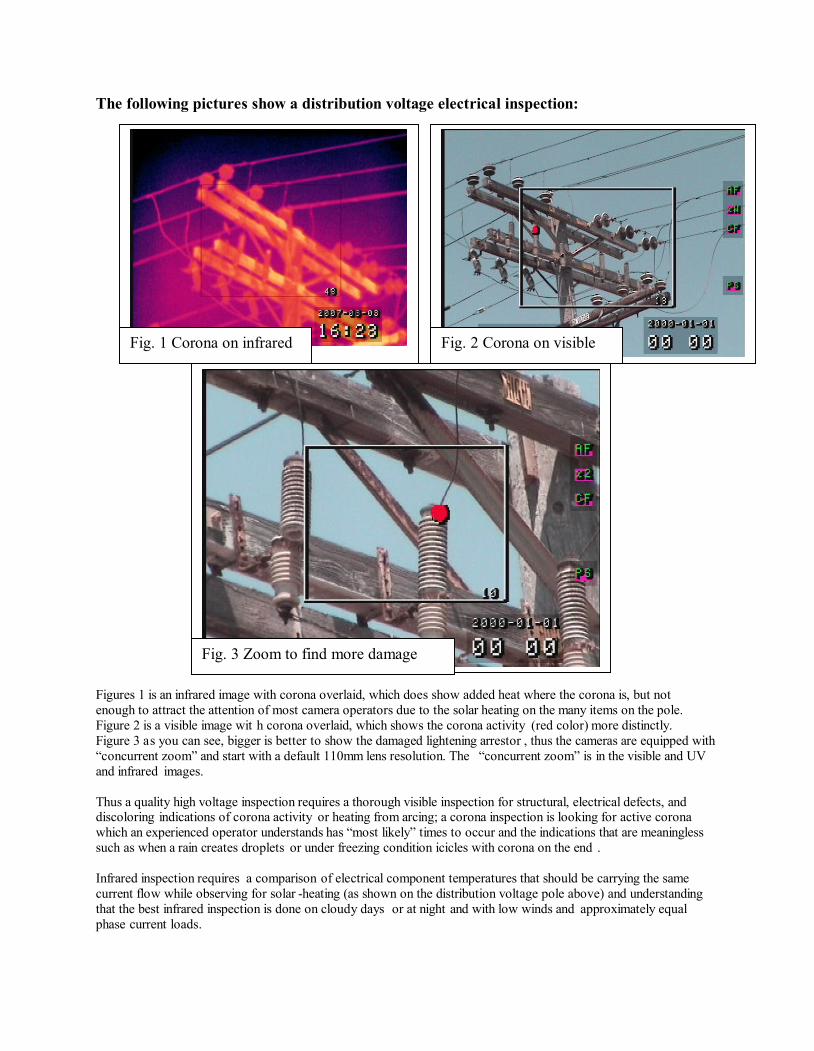
Figure 3 as you can see, bigger is better to show the damaged lightening arrestor , thus the cameras are equipped with
“concurrent zoom” and start with a default 110mm lens resolution. The “concurrent zoom” is in the visible and UV
and infrared images.
Thus a quality high voltage inspection requires a thorough visible inspection for structural, electrical defects, and
discoloring indications of corona activity or heating from arcing; a corona inspection is looking for active corona
which an experienced operator understands has “most likely” times to occur and the indications that are meaningless
such as when a rain creates droplets or under freezing condition icicles with corona on the end .
Infrared inspection requires a comparison of electrical component temperatures that should be carrying the same
current flow while observing for solar -heating (as shown on the distribution voltage pole above) and understanding
that the best infrared inspection is done on cloudy days or at night and with low winds and approximately equal
phase current loads.
Fig. 1 Corona on infrared Fig. 2 Corona on visible
Fig. 3 Zoom to find more damage
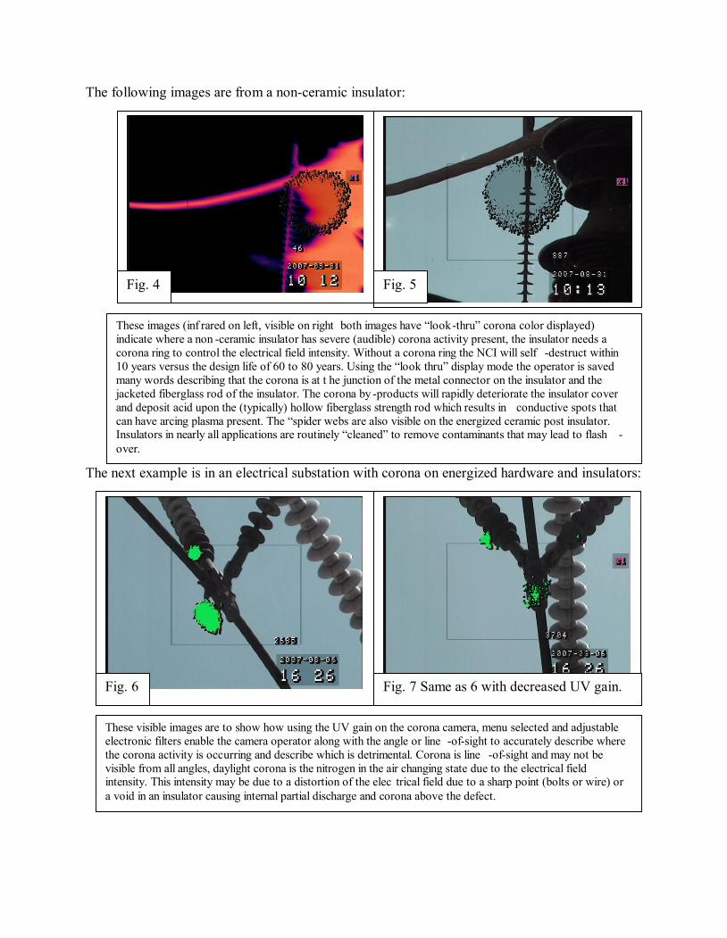
The following images are from a non-ceramic insulator:
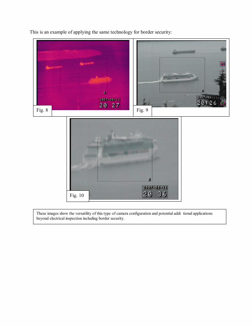
The next example is in an electrical substation with corona on energized hardware and insulators:
These visible images are to show how using the UV gain on the corona camera, menu selected and adjustable
electronic filters enable the camera operator along with the angle or line -of-sight to accurately describe where
the corona activity is occurring and describe which is detrimental. Corona is line -of-sight and may not be
visible from all angles, daylight corona is the nitrogen in the air changing state due to the electrical field
intensity. This intensity may be due to a distortion of the elec trical field due to a sharp point (bolts or wire) or
a void in an insulator causing internal partial discharge and corona above the defect.
Fig. 6 Fig. 7 Same as 6 with decreased UV gain.
These images (inf rared on left, visible on right both images have “look-thru” corona color displayed)
indicate where a non -ceramic insulator has severe (audible) corona activity present, the insulator needs a
corona ring to control the electrical field intensity. Without a corona ring the NCI will self -destruct within
10 years versus the design life of 60 to 80 years. Using the “look thru” display mode the operator is saved
many words describing that the corona is at t he junction of the metal connector on the insulator and the
jacketed fiberglass rod of the insulator. The corona by -products will rapidly deteriorate the insulator cover
and deposit acid upon the (typically) hollow fiberglass strength rod which results in conductive spots that
can have arcing plasma present. The “spider webs are also visible on the energized ceramic post insulator.
Insulators in nearly all applications are routinely “cleaned” to remove contaminants that may lead to flash -
over.
Fig. 4 Fig. 5
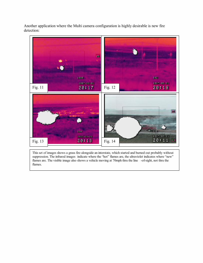
This is an example of applying the same technology for border security:
These images show the versatility of this type of camera configuration and potential addi tional applications
beyond electrical inspection including border security.
Fig. 8 Fig. 9
Fig. 10
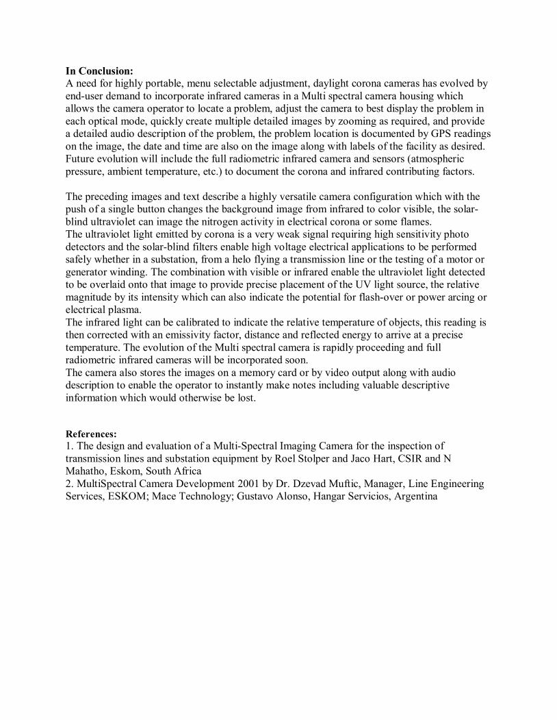
Another application where the Multi camera configuration is highly desirable is new fire
detection:
This set of images shows a grass fire alongside an interstate, which started and burned out probably without
suppression. The infrared images indicate where the “hot” flames are, the ultraviolet indicates where “new”
flames are. The visible image also shows a vehicle moving at 70mph thru the line -of-sight, not thru the
flames.
Fig. 11 Fig. 12
Fig. 13 Fig. 14
In Conclusion:
A need for highly portable, menu selectable adjustment, daylight corona cameras has evolved by
end-user demand to incorporate infrared cameras in a Multi spectral camera housing which
allows the camera operator to locate a problem, adjust the camera to best display the problem in
each optical mode, quickly create multiple detailed images by zooming as required, and provide
a detailed audio description of the problem, the problem location is documented by GPS readings
on the image, the date and time are also on the image along with labels of the facility as desired.
Future evolution will include the full radiometric infrared camera and sensors (atmospheric
pressure, ambient temperature, etc.) to document the corona and infrared contributing factors.
The preceding images and text describe a highly versatile camera configuration which with the
push of a single button changes the background image from infrared to color visible, the solar-
blind ultraviolet can image the nitrogen activity in electrical corona or some flames.
The ultraviolet light emitted by corona is a very weak signal requiring high sensitivity photo
detectors and the solar-blind filters enable high voltage electrical applications to be performed
safely whether in a substation, from a helo flying a transmission line or the testing of a motor or
generator winding. The combination with visible or infrared enable the ultraviolet light detected
to be overlaid onto that image to provide precise placement of the UV light source, the relative
magnitude by its intensity which can also indicate the potential for flash-over or power arcing or
electrical plasma.
The infrared light can be calibrated to indicate the relative temperature of objects, this reading is
then corrected with an emissivity factor, distance and reflected energy to arrive at a precise
temperature. The evolution of the Multi spectral camera is rapidly proceeding and full
radiometric infrared cameras will be incorporated soon.
The camera also stores the images on a memory card or by video output along with audio
description to enable the operator to instantly make notes including valuable descriptive
information which would otherwise be lost.
References:
1. The design and evaluation of a Multi-Spectral Imaging Camera for the inspection of
transmission lines and substation equipment by Roel Stolper and Jaco Hart, CSIR and N
Mahatho, Eskom, South Africa
2. MultiSpectral Camera Development 2001 by Dr. Dzevad Muftic, Manager, Line Engineering
Services, ESKOM; Mace Technology; Gustavo Alonso, Hangar Servicios, Argentina