Embed Size (px)
Citation preview

High Voltage Safetyg g y
Jody J. Nelson, Sr. Advisor, Energy Storage Technologies

Overview
• Importance of HV safety
• HV isolation from vehicle chassis requirement• HV isolation from vehicle chassis – requirement
• Discuss HV safety switch requirements
Hi hli ht d i l t d Fi t D li bl• Highlight e‐drive related First Deliverable requirements
CONFIDENTIAL

Why Spend So Much Time on Safety?
5 Major Vehicle Design Considerations
Bottom 4 are interchangeable d d t
SafetyCrash
Styling dependent on OEM and platform
P f
StylingImage
C f
PerformanceAcceleration, power
ComfortSeating, handling, ride
Featuresi / di / h
CONFIDENTIAL
Expectations: AM/FM Radio, a/c, heaterExtras (Become expectations after time): heated/cooled cup holder, heated seats

Same Conclusion – Safety First
5 Major Vehicle Design Considerations
SafetyCrash
Styling
Safety is always on top:
Whether you are a “Good Samaritan” or a business
P f
StylingImage person, there is the same
conclusion: Safety First
C f
PerformanceAcceleration, power
ComfortSeating, handling, ride
Featuresi / di / h
CONFIDENTIAL
Expectations: AM/FM Radio, a/c, heaterExtras (Become expectations after time): heated/cooled cup holder, heated seats

Why is HV Safety Stressed So Much?
A number of factors influence the human body resistance, but IEC has provided 1 kΩ as an average value
Bodily Effect dc Current [mA]
provided 1 kΩ as an average value
Bodily Effect dc Current [mA]Feeling Sensation 1.0Pain is Felt 62
12 mA @ 12 V
http://www.data‐input.de
“Let-Go” Threshold 76Severe Pain; Breathing Difficulties 90
Heart Fibrillation Occurs 500300 mA @ 300 V
CONFIDENTIAL
Heart Fibrillation Occurs 500
Note: @50 V, body currents are 50 mA. Anything over 50 V must be considered High Voltage
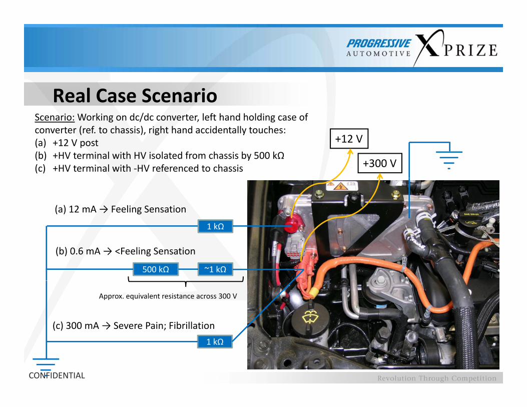
Scenario: Working on dc/dc converter, left hand holding case of ( f h i ) i h h d id ll h
Real Case Scenario
+12 V
+300 V
converter (ref. to chassis), right hand accidentally touches:(a) +12 V post(b) +HV terminal with HV isolated from chassis by 500 kΩ(c) +HV terminal with ‐HV referenced to chassis
1 kΩ
(a) 12 mA → Feeling Sensation
1 kΩ
~1 kΩ500 kΩ
(b) 0.6 mA → <Feeling Sensation
(c) 300 mA → Severe Pain; Fibrillation
Approx. equivalent resistance across 300 V
CONFIDENTIAL
1 kΩ

Real Event During F1 TestingD i F1 t ti i S iDuring F1 testing in Spain, BMW Sauber mechanic
was electronically shocked from the HV KERS (Kinetic E R S t )
Situation could have been if i f h
Energy Recovery System)
worse if it was not for the low energy capacitive
discharge
KERS ll l 400 kJKERS allows only 400 kJ total energy, equating to 60 kW of power for 6.67 seconds over the entire
CONFIDENTIAL
race
This is a magnitude lower energy than a typical HEV battery!

Safety EquipmentRecommended that all Team members have HV safety training: Can seek local National Fire Protection Association (NFPA), National Alternative Fuels T i i C ti (NAFTC)
h k f h l b fl
Training Consortium (NAFTC), or others (OSHA, NEC (NESC), IEEE) for possible resources/courses
Safety glasses
Check for holes by inflating
Hearing protectionHigh Voltage rubber gloves
CONFIDENTIAL
Isolated gloves and safety glasses should be worn at all times when working with the vehicle

Safety Equipment
All tools used on the electrical system should have non‐conductive coatings to prevent accidental contact
CONFIDENTIAL

Personal Protection ItemsMake a list of required safety items for working on the vehicle:
Flash suit
Face shield / hard hat
I l d l
Make a list of required safety items for working on the vehicle:
Insulated tools
Safety glasses / ear plugs
Hot stick
Rubber gloves with leather protectors
DVM / Tic Tracer
Grounding stickg
Protective grounds
Insulation blankets
EH t d h
CONFIDENTIAL
EH rated shoes
Buddy system

Lock‐Out, Tag‐out
• In the workplace always have lock‐outs on items with a potential safety concern:• Lock‐out/de‐energize high voltage equipment before debugging,
working, or installing new equipment• Ensures that only qualified people are working on the vehicle• Minimizes the chance of injury for curious “passers‐by” when nobody is
aroundaround
• LOTO (Lock‐Out, Tag‐out) examples:• Manual Isolation Switch (MIS) in your vehicle (at night put the MIS in a ( ) y ( g p
locked toolbox)• Power source for test equipment (line power, power supply, etc)
• Authorized personnel: Only authorized personnel who are aware of the high
CONFIDENTIAL
Authorized personnel: Only authorized personnel who are aware of the high voltage dangers should work on HV equipment

Lock‐Out/Tag‐Out Devices
Lockable plug covers
Covers for sharp
Circuit breaker lockable covers
ends (pointy guards)
CONFIDENTIAL
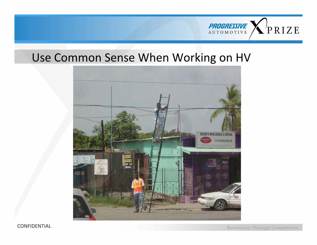
Use Common Sense When Working on HV
CONFIDENTIAL

GFI – Loss of Isolation DetectionThe Ground Fault Isolation (GFI) detection must properly signal loss of isolation, and clearly be shown to the driver, when the electrical isolation becomes < 500 Ω/V, where V is equal to the nominal voltage of the traction battery
• Difficult to achieve with current sensors: A LEM sensor with 1% accuracy cannot sense a 1 mA change i e at 200 A already could have a 2 A errora 1 mA change, i.e., at 200 A already could have a 2 A error
• Can be achieved with precision resistors and Op‐Amp circuit
• Recommendation from Technical Specification: Bender IRDH275 meter with an adjustable response isolation resistance from 1 kΩ to 10 MΩ
150 kΩ GFI
150 kΩ
500 Ω/V
0 kΩ
1
300 V
1 mA
GFI 0 kΩ
1
~2 m
A
3.3 Ω/VkΩ
CONFIDENTIAL
150
Vehicle Chassis
GFI
150 Ω/V1
Vehicle Chassis

Measuring Isolation ResistanceTest Case: Vehicle powered off, all HV
HV positive to vehicle chassis: R2 = ΩHV negative to vehicle chassis: R1 = Ω
Test Case: Vehicle powered off, all HV components connected, using an ohm meter measure the equivalent resistance between the HV bus and vehicle chassis
R2
HV+
Ω
Where R1 and R2 are equivalent resistances of the entire system, but understand your complete HV circuit firstfirst….
R1
HV
Vehicle Chassis
CONFIDENTIAL
HV‐

Measuring Isolation Resistance…but generally there is a passive bleed…but generally there is a passive bleed resistor (RB ≈ 10’s kΩ) across the HV bus to discharge the bus in some minutes after the vehicle is powered down…thus the circuit becomes…
RB
Can approximate if isolation
≈0 Ω
HV+
Ω
the circuit becomes…Ω R2
R1
Can approximate if isolation resistance is much larger than bleed resistor:
R1≈ R2 >> RB
R2’=
R2Ω
Thus, measuring across R2 yields half of the actual R2 (R1||R2 ≈ R2’):RB
R1 Vehicle ChassisHV positive to vehicle chassis: R2 ≈ 2*R2’ ΩHV negative to vehicle chassis: R1 ≈ 2*R1’ Ω
CONFIDENTIAL
HV‐
HV negative to vehicle chassis: R1 ≈ 2 R1 Ω

Measuring Isolation FMVSS 305/SAE J1766Vehicle inspections will be conducted according to FMVSS 305:Vehicle inspections will be conducted according to FMVSS 305:
Ri = lesser of Ri1 Step 1: Measure bus voltageVb must be nom. V or greater
Step 2: Measure HV‐ to chassis Step 3: Measure HV+ to chassis & Ri2
Ri1Ri2 Ri/Vb ≥ 500 Ω/V
CONFIDENTIAL
Step 4: Measure HV‐ to chassiswith Ro (500 x Vb)
Step 5: Measure HV+ to chassiswith Ro (500 x Vb)
Equipotential Bonding
All HV components enclosed by conductive casing must have equipotential (conductive) bonding between other conductiveequipotential (conductive) bonding between other conductive enclosed casing and vehicle chassis
The maximum allowable resistance of the bonding is 0 1 ΩThe maximum allowable resistance of the bonding is 0.1 Ω
Without this, the GFI becomes useless in an event when the HV is shorted to the conductive case; Since the case is floating, the GFI cannot detect loss of isolation to the vehicle chassis
CONFIDENTIAL

EDS (e‐Stop Button)Emergency Disconnect Switches (EDS) are required in the event of a run‐away condition or otherEmergency Disconnect Switches (EDS) are required in the event of a run away condition or other unsafe situations. It is required at full‐load to safely and immediately disconnect the HV source from the remainder of the vehicle. The EDS contactor should be located, ideally, within the HV battery case, otherwise not to exceed 3 feet from the HV battery.
V B
atte
ry
erte
r
HV
Inv
CONFIDENTIAL
Still can have HV up to this point

Inertia SwitchThe Inertia Switch should activate the EDS to open the HV circuit in the event of an accidentThe Inertia Switch should activate the EDS to open the HV circuit in the event of an accident exceeding an acceleration of 8 G
y
Inertia switch
HV
Bat
tery
nver
ter
HIn
CONFIDENTIAL
Still can have HV up to this point

MIS (Service Switch)A Manual Isolation Switch (MIS) is required to disconnect the HV from the system to allow forA Manual Isolation Switch (MIS) is required to disconnect the HV from the system to allow for working on the vehicle safely• The MIS switch should be after the EDS in the event the EDS was deployed so that there
remains no voltage at the terminals of the MIS• The MIS must be disconnected by physically pulling and separating (not by electric actuation)The MIS must be disconnected by physically pulling and separating (not by electric actuation)
the contacts or terminals that lead to the high‐voltage system• The MIS is not intended to open the HV circuit under load
Common for current production HEVs to have MIS located directly on the HV battery
CONFIDENTIAL

Warning Labels
• Orange cables easy to see
CONFIDENTIAL
• Orange cables easy to see• Warning labels on all HV components

Environmental Requirements
k h h ll b d f hMake the assumption that it will be raining at MIS during some of the events
Be certain to make all preventive measures on all HV components so p pthat they are safe from rain and accidental spills (the soda pop spill test)
Be aware of common environmental test for OEMs:
• Low/high temperature endurance
• Thermal cycles
• Thermal shock
• Handling drop test
• Dust (DIN‐40‐050)
• Water intrusion• Humidity endurance
• Solar radiation
Vib i
Water intrusion
• High pressure steam jet exposure (DIN 40‐050)
• Salt water immersion
CONFIDENTIAL
• Vibration
• Mechanical shock
• Salt water immersion
• Salt fog

HV Battery Thermal Management System
1 D t ti T h ll id d t ti f th i b tt t t1. Documentation: Teams shall provide documentation of their battery temperature management strategy and provide a test plan illustrating how their design will be tested on the vehicle. First Deliverable
2 Testing: Teams are required to demonstrate their design works as intended with the2. Testing: Teams are required to demonstrate their design works as intended with the proper vehicle reaction based on their test plan. Second Deliverable
The test plan should include:
• Vehicle operating state; i.e. idle
• Description of how the battery temperature will be simulated:
• Pulling a thermocouple off and heating it externally (D‐4.4.8)g p g y ( )
• Using SW to change the temperature parameter
• The simulated temperature should be step or linear increases up to the maximum rated temperature
CONFIDENTIAL
p
• Teams should include expected vehicle reaction at every defined temperature threshold

Example HV Battery Thermal Management
Illuminate warning lamp
Set cooling system to maximum fan speed/flow rate
Torque Available [multiple]
k2
[multiple] k1Vehicle Shutdown / HV Battery Pack Disconnected
Batt. Temp [°C]
k0
t t t t
CONFIDENTIAL
Batt. Temp [ C]t0 t1 t2 t3

Example: Thermal Management Failure
CONFIDENTIAL

Example: Thermal Management Failure
CONFIDENTIAL

Example: Thermal Management Failure
CONFIDENTIAL

Erroneous Propulsion and MonitoringECE R100 5 2 2 3: “Unintentional acceleration deceleration and reversal of the driveECE R100 5.2.2.3: Unintentional acceleration, deceleration, and reversal of the drive train shall be prevented. In particular, a failure (e.g. in the power train) shall not cause more than 0.1 m movement of a standing un‐braked vehicle.”
Teams shall provide documentation detailing how their control system addresses the p g yissue of erroneous propulsion. Documents should include:
• Vehicle reaction to loss or erroneous values of critical vehicle control signals such as electric motor position, phase currents, voltages, commanded torque signal, throttle position, etc.
• All preventive measures taken to prevent unintentional movement of the vehicle
• Describe monitoring strategy: i.e. if a torque transducer is used to measure torque, how is it verified; i.e. by a calculation. What is the plausibility check for sensors; i.e. how are the current sensor values verified?
Note: For ICE vehicles, FMVSS 124 provides regulation of ICE up to WOT when an Accelerator Throttle Position Sensor Electronic Control Module Throttle Plate Actuator
CONFIDENTIAL
Accelerator Throttle Position Sensor, Electronic Control Module, Throttle Plate Actuator Motor, and Throttle Plate Position Sensor are disconnected

Erroneous Propulsion – Example Test
To test for unintentional movement of the vehicle, the following test can be performed:
• Place running vehicle in neutral on a flat, smooth surface; vehicle should not move
• If using a PM motor, apply maximum ID current at 0 IQ current; vehicle should not move more than 10 cm
• If using an accelerator potentiometer create an open and short• If using an accelerator potentiometer, create an open and short circuit of the “throttle‐by‐wire”; vehicle should not move more than 10 cm
CONFIDENTIAL

Vehicle DiagnosticsIn production vehicles, diagnostics make up 80% of the SW whereas the actual propulsion code is only around 20%
The Judging Panel considers vehicle diagnostics an essential requirement of all vehicles
It is required in the First Deliverable to describe in detail the protection (fail‐safe) strategy for the below conditions
If the Judging Panel is not satisfied with the response, further evidence or visit may be required
Please provide HIL results when possible. Include control diagrams and a software description or hardware schematics:
• HV short‐circuit on HV dc and 3‐phase ac sides• How is a short detected? What is the vehicle reaction to a short?• How is a short detected? What is the vehicle reaction to a short?• HV over‐current: thresholds, vehicle reaction• HV over‐voltage: thresholds, vehicle reaction• Over‐temperature of the power electronics, electric motors, and HV battery
CONFIDENTIAL
• Runaway motor (loss of speed sensor) • Loss of low voltage (supplying your controller)
Vehicle Inspection Preview
• Visual inspection of all electrical components and cables/connectors• Fusing, proper connectors, finger‐proofing, strain‐relief, routing (no chaffing
or exposure to sharp edges), closeness to heat sources, waterproofingor exposure to sharp edges), closeness to heat sources, waterproofing
• Inspection of all HV safety related switches and isolation detection
• Resistance measurement of all conductive HV enclosures to the vehicle chassischassis
• Inspection of HV battery and thermal management system
• EDS will be tested under load
• Vehicle isolation will be checked per FMVSS 305 requirements
• Removal of the 12 V power source while vehicle is operating
• Various diagnostic features will be tested
CONFIDENTIAL

Summary• All vehicle designs are centered around safety• All vehicle designs are centered around safety
Will be first priority in vehicle inspections• Accidental contact of high voltage can lead to dangerous body currents
Takes < 100 mA to be very dangerous• The vehicle chassis must be isolated from the HV bus and must be monitored at all
timesWill be tested during vehicle inspections: must meet FMVSS 305
• There are a number of required HV safety switches called out in the technicalThere are a number of required HV safety switches called out in the technical specification
Must address all questions in First Technical Deliverable• HV battery safety and thermal management are critical considerations in the
competitionFirst Technical Deliverable must provide test plan; Second Technical Deliverable
must provide test results• Teams should be aware of fault and over‐limit conditions and should deal with
CONFIDENTIAL
them properlyFirst Technical Deliverable must provide details of diagnostics


![Sin título-1 · gplithwm 02430 gp cr2430 gp cr2430 gp urwum cr2430 super value —super super high voltage (4lr44] 476 a. high voltage high voltage voltage voltage](https://img.pdfslide.net/doc/110x75/5fc9a1e0f8d7c57bb3741c3c/sin-ttulo-1-gplithwm-02430-gp-cr2430-gp-cr2430-gp-urwum-cr2430-super-value-asuper.jpg)