Embed Size (px)
Citation preview

high voltagetesting equipment
HIGH VOLTAGE TESTING & MEASUREMENT EQUIPMENT CATALOG


high voltagetesting equipment
1www.kep.ua 1
KEP Power Testing Ltd. aims to deliver quality High Voltage testing equipment to the utilities, testing service companies, electrical contractors and large industrials worldwide.
Our wide product range includes technically advanced, portable Test Van solutions for integral HV maintenance, as well as easy to use products for High Voltage testing, diagnostics, evaluation, and preventive maintenance testing of electrical substation apparatus, power cables, and other objects designed to operate under medium to high voltage conditions.
All our equipment is designed and manufactured according to Quality Management System based on ISO 9001 standard, certified by Intertek plc., while the in-house ISO/IEC 17025-certified calibration laboratory is ensuring the accuracy of supplied apparatus.
Keeping in touch with our customers around the world, permanently combined with market analysis and quick response to its changes makes KEP well-equipped for developing progressive solutions for wide variety of customer needs.
Your KEP Power Testing team
high voltagetesting equipment
www.kep.ua
high voltagetesting equipment
2 www.kep.ua2
TABLE OF CONTENTS
PRODUCTION FACILITIES .........................................................................................4
CABLE FAULT LOCATION
VEHICLE-BASED SYSTEMS
General overview .................................................................................6
ETL-8V Compact vehicle-based systems .........................................8
ETL-40V Vehicle-based systems ...................................................... 10
ETL-80V Vehicle-based systems ...................................................... 14
COMPACT SYSTEMS
SWG-12/1100R Portable cable fault location system ............... 16
STANDALONE EQUIPMENT
RIF-9 Digital impulse reflectometer ................................................ 18
LFG-50, LFG-200 Low-frequency generator .............................. 20
PT-14 Tracer, P-900 Ground microphone .................................. 22
Cables for HV testing ....................................................................... 23
HV TESTERS FOR POWER NETWORKS OBJECTS
PORTABLE AC/DC HIPOTS
VLF-60 Cabel Insulation Tester ......................................................... 24
HVTS-70/50 High-voltage testing system .................................... 26
HVT-70/50 High-voltage testing system ....................................... 26
AC/DC HIPOTS HP-SERIES
HVTS-HP High-voltage insulation tester ....................................... 28

high voltagetesting equipment
3www.kep.ua 3
TABLE OF CONTENTS
CIRCUIT BREAKERS TESTERS
UPA-1 Automatic circuit breaker tester .................................................... 30
UPA-3 Automatic circuit breaker tester .................................................... 30
UPA-6 Automatic circuit breaker tester .................................................... 30
UPA-10 Automatic circuit breaker tester ................................................. 30
UPA-16, UPA-20 Automatic circuit breaker tester ............................... 31
OIL TESTERS
OLT-80A Oil tester ........................................................................................... 32
OLT-90A Oil tester ........................................................................................... 32
OLT-100A Oil tester ........................................................................................ 32
OLT-80M Oil tester .......................................................................................... 32
OLT-90M Oil tester .......................................................................................... 32
OLT-100M Oil tester ....................................................................................... 32
C-80, C-100 Oil tester calibrator ................................................................ 35
Tangens-3M Oil dissipation factor meter ............................................... 36
RESONANT TESTING SYSTEMS
UIG-25/50/70-180, UI-15/225 ................................................................ 37
UIG-35/70/100-750, UIG-35/70/100-800 .......................................... 38
PACKAGE .................................................................................................................... 40
DEALERS .................................................................................................................... 42

high voltagetesting equipment
4 www.kep.ua4
PRODUCTION FACILITIES
EQUIPMENT CONSTRUCTION
KEP Ltd. HEADQUARTERS IN KHARKOV, UKRAINE
EQUIPMENT ADJUSTMENT

high voltagetesting equipment
5www.kep.ua 5
PRODUCTION FACILITIES
LATHE WORK
ENGINEERING TEAM
STEEL SHEET CUTTING
MILLING USING CNC
TRANSFORMERS WINDING
TURNING AND MILLING USING CNC TURNING AND MILLING USING CNC
CABLE TEST VAN ASSEMBLING
SF6
FILLING EQUIPMENT HV COILS WINDING
UV-PRINTING

high voltagetesting equipment
6 www.kep.ua6 CABLE FAULT LOCATION
General overview
The new generation of KEP Vehicle-based systems for cable testing and fault locating provides you with high-efficient, safe and reliable work on all kinds of LV and MV cables used in power networks.
We always consider individual customer needs, thus
main parameters as well as a set of auxiliary equipment, which is delivered with the system, are object to change upon customer's request.
Our customer's safety is our first priority. KEP cable fault locating systems are built to meet all essential safety standards. As a base all our vehicle-based systems have:
• Earthing monitoring
All systems have safety earthing, operational earthing and auxiliary earthing. The independent GCU-3 module performs a permanent monitoring of resistance between safety earthing and operational earthing as well as a voltage between safety earthing (chassis) and auxiliary earthing. System will be stopped if these parameters exceed the tolerance limits.
• Control unit interlock
The control unit of each system always have an interlock. This prevents unauthorized energizing the high-voltage part of the system.
• Emergency stop button
Operator should always have a possibility to stop the system in case of any emergency. The emergency stop button is made to be easy reachable and fully independent from other system controls. Once this button has been pressed the system will be stopped immediately.
• Protection from incorrect HV connection
HV and LV connectors are made in a way to prevent their wrong connection.
• Rear doors monitoring
The system always monitors whether the rear doors of the vehicle (high-voltage compartment) are closed firmly. If the responsible sensors return fault the system is stopped immediately.
• Overvoltage protection
Inputs of a Time-Domain Reflectometer have overvoltage protection 400V CAT IV.
• Input current monitoring
The input current is monitored by internal monitoring system to prevent input circuits overheat.
• Isolating transformer
Insolating transformer is a basic option for increasing the safety level.
• Circuit breakers
The primary connection to mains has a relevant automatic circuit breaker, which trips out in a case of overcurrent.
Discription
Safety
Grounding control unit Visible shorting bar

high voltagetesting equipment
7www.kep.ua 7CABLE FAULT LOCATION
General overview
Compact systems can be based on vehicles of a size similar to VW Caddy. Full-size systems can be based on vehicles of a size similar to Mercedes Sprinter.
Furniture options as well as auxiliary equipment (air conditioner, additional heater, etc.) installed according to customer’s demands.
System base
Vehicles for:compact systems full-size systems

high voltagetesting equipment
8 www.kep.ua8 CABLE FAULT LOCATION
ETL-8VCompact vehicle-based system
ApplicationThe ETL-8V is an compact vehicle-based system,
which is used for the following purposes:
• Cable testing up to 8 kV DC
• Cable faulty place burning
• Fault prelocating using Time-Domain
Reflectometer RIF-9 working in:
• TDR mode
• Arc-Reflection mode
• Impulse Current Mode
• Voltage coupling mode
• Precise pinpointing with ground microphone
• Cable route tracing (optional).

high voltagetesting equipment
9www.kep.ua 9CABLE FAULT LOCATION
ETL-8V Compact vehicle-based system
Technical specifications
Parameter Value
GENERAL parameter
Input voltage, V 230 ± 23Frequency, Hz 50 ± 1Power consumption, kVA, max 1.0
TEST MODE
Output DC voltage range, kV 0 – 8Output DC current range, mA 0 – 10
BURN MODE
Output DC voltage range, kV 0 – 8Output DC current range, mA 0 – 100
SURGE MODE
DC voltage ranges, kV 2 / 4 / 8
Output energy, J, max 1000
Timer set (automatic surge mode) 3 – 15 secondsManual single surgeFlexible voltage change during automatic operationPinpointing with an acoustic receiver
PRELOCATION MODE1
MethodsTDR / Arc reflection/
Impulse current/ Voltage coupling
Automatic distance measuringSaving cable parameters into Reflectometer non-volatile memorySaving reflectograms either to Reflectometer non-volatile memory or USB flash drive
CABLE TRACING MODE2
Cable tracing using 50W audio-frequency generator with frequencies 491/ 982/ 8440 Hz with a receiver
1 - Learn more from KEP RIF-9 page;2 - Learn more from KEP LFG-50 page.

high voltagetesting equipment
10 www.kep.ua10 CABLE FAULT LOCATION
ApplicationETL-40V is a modular test equipment, which is
designed for testing and fault location of both LV and MV cables. The key parameters are designed flexible to satisfy customer’s specific requirements.
Vehicle-based system ETL-40V allows:
• DC cable testing up to 40 kV with 300 mA max.
current
• Burning up to 20 kV / 1 A
• Surge energy up to 2400 J
• Precise fault prelocating using Time-Domain
Reflectometer RIF-9 working in:
• TDR mode
• Arc-Reflection mode
• Impulse Current Mode
• Voltage coupling mode
• Automatic test procedure
• Fault location using step voltage mode (optional)
Vehicle-basedsystem ETL-40V

high voltagetesting equipment
11www.kep.ua 11CABLE FAULT LOCATION
Vehicle-basedsystem ETL-40V

high voltagetesting equipment
12 www.kep.ua12 CABLE FAULT LOCATION
Technical specifications
Parameter Value
GENERAL parameter
Input voltage, V 230 ± 23Frequency, Hz 50 ± 1Power consumption, kVA, max 2.0
TEST MODE
Output DC voltage range, kV 0 – 40Output DC current range, mA 300
BURN MODE
Output DC voltage range, kV 0 – 20Output DC current range, A 1
SURGE MODE
Ranges, kV4 / 8 / 16 / 32(8 / 16 / 32)
Output energy, J, max2000
(at each range)Timer set (automatic surge mode), seconds
5 – 15
Manual single surge
Parameter Value
Flexible voltage change during automatic operationPinpointing with an acoustic receiver
PRELOCATION MODE
MethodsTDR / Arc reflection/
Impulse current/ Voltage coupling
Automatic distance measuringSaving cable parameters into Reflectometer non-volatile memorySaving reflectograms either to Reflectometer non-volatile memory or USB flash drive
CABLE TRACING MODE
Cable tracing using 50W audio-frequency generator with frequencies 491/ 982/ 8440 Hz with a receiver
Power Panel Operation Control Panel Surge Switch Panel
Vehicle-basedsystem ETL-40V
high voltagetesting equipment
13www.kep.ua 13CABLE FAULT LOCATION
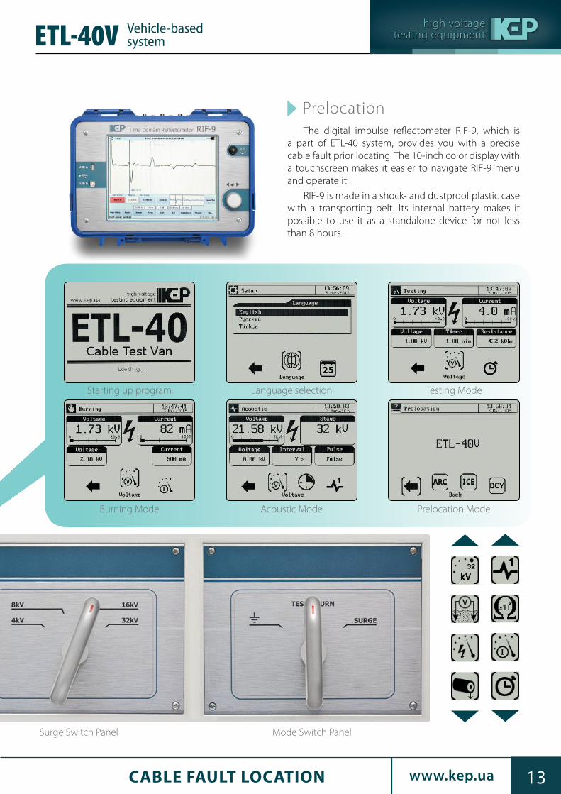
Surge Switch Panel Mode Switch Panel
PrelocationThe digital impulse reflectometer RIF-9, which is
a part of ETL-40 system, provides you with a precise cable fault prior locating. The 10-inch color display with a touchscreen makes it easier to navigate RIF-9 menu and operate it.
RIF-9 is made in a shock- and dustproof plastic case with a transporting belt. Its internal battery makes it possible to use it as a standalone device for not less than 8 hours.
Starting up program
Burning Mode
Language selection
Acoustic Mode
Testing Mode
Prelocation Mode
Vehicle-basedsystem ETL-40V

high voltagetesting equipment
14 www.kep.ua14 CABLE FAULT LOCATION
ETL-80VVehicle-basedsystem
ApplicationThe ETL-80V is a modular system, which is used
for the following purposes:
• DC cable testing up to 80 kV
• Converting high-resistive cable faults into low-
resistive with a use of burn generator
• Prelocating faulty places with a use of Time
Domain Reflectometer RIF-9
• Cable route tracing with a use of 200 W low-
frequency generator and receiver
• Precise pinpointing using a surge wave generator
with a ground microphone

high voltagetesting equipment
15www.kep.ua 15CABLE FAULT LOCATION
ETL-80V Vehicle-basedsystem
Technical specifications
Parameter Value
GENERAL parameter
Input voltage, V 230 ± 23Frequency, Hz 50 ± 1
Power consumption, kVA, max3.0 (3.5 for 40A burn gener-
ator)
TEST MODE
Output DC voltage range, kV 0 – 80Output DC current range, mA 0 – 580
BURN MODE
Output DC voltage range, kV 0 – 20Output DC current range, mA 0 – 40
SURGE MODE
DC voltage ranges, kV 4 / 8 / 16 / 32
Output energy, J, max 2560 (at each range)
Timer set (automatic surge mode), seconds 3 – 15Manual single surgeFlexible voltage change during automatic operationPinpointing with an acoustic receiver
PRELOCATION MODE
MethodsTDR / Arc reflection/ Impulse
current/ Voltage coupling/ Arc reflection + burn
Automatic distance measuringSaving cable parameters into Reflectometer non-volatile memorySaving reflectograms either to Reflectometer non-volatile memory or USB flash drive
CABLE TRACING MODE
Cable tracing using 50W audio-frequency generator with frequencies 491/ 982/ 8440 Hz with a receiver

high voltagetesting equipment
16 www.kep.ua16 CABLE FAULT LOCATION
Portable cable fault location system SWG-12/1100R
SWG-12/1100R portable cable fault location system is a complex solution for safe, fast and easy locating a faulty place on low and medium underground voltage cables. It includes a powerful high-voltage unit, which has a test, burn and surge generation modules, and a time-domain reflectometer for locating faults on cables.
The high-voltage unit of the system provides with high-power up to 1100 Joules surges at 3; 6 and 12 kV ranges. At each range, the output voltage is smoothly adjustable. The rate of surge waves can be smoothly adjusted. The single manual shot option is also included. The DC output mode is provided for quick fault diagnostics. The 100 mA burn mode is available.
Digital impulse reflectometer (TDR) RIF-9 provides you with 10.4-inch bright high-contrast TFT display with touchscreen. The 800 × 600 pixels resolution makes the picture sharp. The touchscreen allows an operator navigate through the menu fast and easy. An alternative way of navigation is included. It is provided with a control knob.
Application
Description

high voltagetesting equipment
17www.kep.ua 17CABLE FAULT LOCATION
Portable cable fault location system SWG-12/1100R
Technical specifications
Component Quantity
SWG-12/1100R 1Bag for cables 1User manual 1Connecting cables set (may vary on customer’s demand)
6 m each
Component Quantity
LFG-50 Audio frequency generator 1P-900 Surge wave locator set 1
TDR parameter Value
Distance measurement ranges, m @ v/2 = 100 m/µs
60/120/ 250/ 500/1000/2000/5000/ 10000/20000/50000/120000
Resolution, m 0.5 @ v/2 = 100 m/µs0.4 @ v/2 = 80 m/µs
Sampling rate, MHz 200Gain, dB -33 – 104Output impedance (10 Ω steps), Ω 10 – 500
Propagation velocity (v/2), m/µs 50.0 – 150.0
Averaging reflectograms number, max 64Time domain accuracy 0.2 % of FSPulse amplitude, V 45Pulse width, ns 10 – 100 000
Operation modes TDR (reflection measurement)ARC (arc-reflection)
Control Touchscreen and control knobConnectivity RS-485, USB
Internal data storage 4 Gb (not less than 1000 reflectograms with data)
Display 10.4”, 800 x 600 TFT, touch-sensitive
Accessories
RIF-9 integrates a multiple ways of fault prelocation. It can be used either as a standalone device in TDR mode or in a conjunction with HV-module, working in arc reflection mode.
RIF-9 has USB interface. The package content
includes software for PC (optional), which allows working with saved reflectograms. The firmware can be easily updated through USB interface by inserting a flash drive.
GENERAL parameter Value
Input voltage, V 230 ± 23Frequency, Hz 50 ± 1Power consumption, kVA, max 1.0Dimensions (W × H × D) , mm 731 × 1120 × 533Net weight, kg 113
HV-module parameter
TESTING MODE
Output DC voltage, kV 0 – 12Output DC current, mA 1 / 10
BURNING MODE
Output DC voltage range, kV 0 – 12Output DC current range, mA 0 – 100
SURGE MODE
Ranges, kV 3 / 6 / 12
Surge rate, s 3 – 15 orsingle shot
Max. output energy, J 1100
Bag for cabels
Package contents

high voltagetesting equipment
18 www.kep.ua18 CABLE FAULT LOCATION
Digital impulse reflectometer RIF-9
Application
• RIF-9 provides you with 10.4-inch bright high-contrast TFT display with touchscreen. The 800 × 600 pixels resolution makes the picture sharp. The touchscreen allows an operator navigate through the menu fast and easy. An alternative way of navigation is included. It is provided with a control knob.
• RIF-9 integrates a multiple ways of fault prelocation. It can be used either as a standalone device in TDR mode or in a conjunction with HV-module (e.g. Cable test van or Surge wave generator), working in arc reflection (ARC), impulse current (ICE) and decay modes. A high-capacity internal battery allows working up to 8 hours.
• RIF-9 has both RS-485 and USB interfaces. The package content includes software for PC (optional), which allows working with saved reflectograms. The firmware is easily updated through USB interface by inserting a flash drive.
Description
Battery powered digital impulse reflectometer (TDR) RIF-9 designed for determining the distance to a fault in communication and power cables.
Digital impulse reflectometer RIF-9 allows:
• Determining the distance to a fault or discontinuity in symmetric and asymmetric cables using a location (time domain reflection) method
• Measuring the length of a cable (including those wound on a drum) or distance to a fault or a short circuit
• Storing and processing the results of measurements both internally or using a supplied PC software
• As part of a Cable Test Van, determining the distance to a fault or discontinuity in cables with length of up to 100 km for all possible fault types without the need of preliminary full cable sheath burning

high voltagetesting equipment
19www.kep.ua 19CABLE FAULT LOCATION
Digital impulse reflectometerRIF-9
Technical specifications
RIF-9 workplay screenshot
Parameter Value
Distance measurement ranges, m @ v/2 = 100 m/µs
60 / 120 / 250 / 500 / 1000 / 2000 / 5000 10000 / 20000 / 50000 / 120000
Resolution, m 0.5 @ v/2 = 100 m/µs0.4 @ v/2 = 80 m/µs
Sampling rate, MHz 200
Gain, dB -33 – 104
Output impedance (10 Ω steps), Ω 10 – 500
Propagation velocity (v/2), m/µs 50.0 – 150.0
Averaging reflectograms number, max 64
Time domain accuracy 0.2 % of FS
Pulse amplitude, V 45
Propagation velocity (v/2) resolution, m/us 0.1
Pulse width, ns 10 – 100 000
Operation modes TDR / ARC / ICE / Decay
Control Touchscreen and control knob
Connectivity RS-485, USB
Internal data storage4 Gb (not less than 1000 reflectograms with data)
Display10.4”, 800 x 600 TFT,
touch-sensitive
Internal battery12 V (8 hours of operating
when fully charged)
External power adaptorInput 230 V 50 HzOutput 24 V DC
Power consumption, W, max 36
Dimensions (W × H × D), mm 366 × 178 × 270
Net weight (with internal battery), kg 8.0
RIF-9 bag for cabels

high voltagetesting equipment
20 www.kep.ua20 CABLE FAULT LOCATION
Low-Frequency Generator LFG-50 LFG-200
Application
Description
Package contents
Low-frequency generator LFG-50, when operated in conjunction with a receiver, can be used for locating as well as tracing underground metal communications, such as any cables with metal cores as well as metal pipes. In addition, it provides operator with a quick detection of short circuits on cables as well as with an identification of a cable in a bunch.
LFG-50 is a 50 W low-frequency generator with ability to inject a signal of three frequencies via direct connection to an object or via internal transmission loop antenna, which is built-in a cover lid. Basic frequencies are 491, 982 and 8440 Hz. There are options of using a single-frequency or multi-frequency signals at the output.
The power of LFG-50 output signal can be adjusted up to 50 W with 2.5 W steps. This signal can be transmitted constantly or broken into separate blocks of 50 % duty cycle with 1 s repetition rate.
A load matching is made automatically. Main parameters, such as output power, load impedance, selected frequency are shown on OLED display. If a load is higher than 1000 Ω LFG-50 automatically switches into output voltage setting mode. The output overload protection will trip, when operating on short-circuit loops (lower than 0.5 Ω).
Component Quantity
LFG-50 1Soft case 1Power cable 1Signal connecting wires 2“Crocodile” connectors 3User manual 1Fuse 10 A 4Fuse 1 A 1
LFG-200P
high voltagetesting equipment
21www.kep.ua 21CABLE FAULT LOCATION
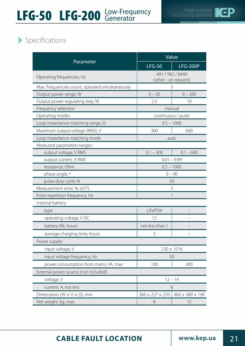
Low-Frequency GeneratorLFG-200LFG-50
Specifications
ParameterValue
LFG-50 LFG-200P
Operating frequencies, Hz491 / 982 / 8440
(other - on request)
Max. Frequencies count, operated simultaneously 3
Output power range, W 0 – 50 0 – 200
Output power regulating step, W 2.5 10
Frequency selection manual
Operating modes continuous / pulse
Loop impedance matching range, Ω 0.5 – 1000
Maximum output voltage (RMS), V 300 600
Loop impedance matching mode auto
Measured parameters ranges:
output voltage, V RMS 0.1 – 300 0.1 – 600
output current, A RMS 0.01 – 9.99
resistance, Ohm 0.5 – 1000
phase angle, º 0 – 90
pulse duty cycle, % 50
Measurement error, %, of FS 5
Pulse repetition frequency, Hz 1
Internal battery:
type LiFePO4 –
operating voltage, V DC 12 –
battery life, hours not less than 1 –
average charging time, hours 3 –
Power supply:
input voltage, V 230 ± 10 %
input voltage frequency, Hz 50
power consumption from mains, VA, max 100 400
External power source (not included):
voltage, V 12 – 14
current, А, not less 8
Dimensions (W × H × D), mm 366 × 227 × 270 460 × 380 × 190
Net weight, kg, max 8 15

high voltagetesting equipment
22 www.kep.ua22 CABLE FAULT LOCATION
Ground microphone P-900
Ground microphone P-900 should be used with an auxiliary frequency generator of 1024 ± 2 Hz / 2048 ± 2 Hz and no less than 200 W of output power at the load range from 0.5 to 200 Ohms (e.g., LFG-50) when searching using the inductive method.
Application
Acoustic sensorHeadphones
Parameter Value
Sensitivity at max / min amplification 20 uV / 500 mV
Pass band (-3 dB) in “1024Hz” / ”2048Hz” mode, Hz
10 / 12
Pass band in audio frequency mode, Hz 20 – 2200
Power source 5 АА × 1.2 V NiMh
Duty time, hours 16
Dimensions (W × H × D), mm 180 × 70 × 120
Net weight (batteries included) 0.65
You can also try to use it virtually from our web-site (Adobe Flash Player required)
Technical specifications
Fast and accurate search for power cables and other communications, identification of coating defects and the depth, followed by mapping.
Parameter Value
Operating frequencies, Hz 491 / 982 / 8440
Bandwidth:
RADIO mode, kHz 10 − 36
ONLINE mode, Hz 48 − 10 000
Sensitivity, μV 1
Track depth meas. error, %, max 5
Dimensions, mm 700 × 300 × 140
Net weight, kg, max 2.4
Application
Technical specifications
Receiver PT-14 Tracer

high voltagetesting equipment
23www.kep.ua 23CABLE FAULT LOCATION
ApplicationFlexible silicone frostproof high-voltage cables KEP-100,
KEP-70 and KEP-70p are suitable for high-voltage testing both as part of ETL vans and separately, as well as for use in the measuring circuits of tgδ insulation (KEP-12t).
Сable test vans ETL-40V and ETL-80V made by
KharkovEnergoPribor as a means of testing and detecting cable faults are are both supplied with flexible silicone frostproof highvoltage cables, which retains its flexibility at the temperatures as low as minus 40˚С.
Cables for HV testing
KEP-70p
KEP-12t
KEP-70
KEP-100
KEP-70 cable structure follows the structure КЕР-100
KEP-100 cable cross section
Main insulation silicone rubber
Core (flexible tinned copper S =4.0 mm2)
Semiconductive layer
Main insulationsilicone rubber
Screen(100% aluminium foil)
Semiconductive layer
PVC insulation
Core (flexible tinned copper wire S =0.5 mm2)
Protective silicone rubber sheath
Main insulationsilicone rubber
Screen(tinned copper S = 4.0 мм2)
Core (flexible tinned copper S =4.0 mm2)
Synthetic fiber
Semiconductive layer
Semiconductive layer
Cable drums for KEP-70 cables

high voltagetesting equipment
24 HV TESTERS FOR POWER NETWORKSwww.kep.ua
VLF-60 Cable Insulation Tester made by KEP is a very low frequency high potential tester that ensures efficient testing and fault location on medium voltage cables.
Very low frequency (VLF) testing involves applying frequency in the range of 0.01 to 0.1 Hz to the cable
under test, which is non-destructive to insulation of proper quality, but is enough to detect cable faults. Compared to DC cable testing, which can be damaging to good insulation, VLF testing does not have such a detrimental effect on the cable being tested.
Application
VLF-60Cable Insulation Tester

high voltagetesting equipment
25HV TESTERS FOR POWER NETWORKS www.kep.ua
Parameter Value
Output Voltage
Sinusoidal 0 – 62 kV peak / 0 – 44 kV RMS
DC ± 0 – 60 kV
Squarewave 0 – 60 kV
Accuracy ± 1 %
Resolution 0.1 kV
Output Curent
Sinusoidal (RMS) 26 mA
DC / Squarewave 40 mA
Accuracy ± 1 %
Resolution 1 μA
Output Frequency0.01 – 0.1Hz in steps of 0.01 Hz (default 0.1 Hz) – auto
frequency selection
Output Load
1 μF @ 0.1 Hz @ 44 kV RMS5.0 μF @ 0.01 @ 44 kV RMS
10.0 μF max capacitance (at lower frequency and Voltage)
Output Modes
VLF AC Sinewave
VLF AC Squarewave
DC (positive or negative polarity)
Vacuum Bottle Test Mode (DC)
Cable Jacket / Sheath Testing
Sheath Fault Location
Breakdown Mode
Fault Condition Mode
Fault Trip Mode
Metering
Voltage and Current True RMS and / or peak
Capacitance 0.1 nF to 20 μF Range
Resistance 0.1 MΩ to 20 GΩ
WaveformReal time oscilloscope display of actual
output voltage waveform
Safety50 / 60 Hz – 12 kV Feedback Protection /
Dual Discharge Device (internal)
Duty Cycle Continuous
Computer Interfaces USB, RS-485
Display Color touchscreen TFT 5.7 “ (115 × 86 mm)
Input Voltage (110 to 240) V AC ±10 %, 50 / 60 Hz
Consumption Power 1.2 kVA
Dimensions (H × W × D) 530 × 580 × 410 mm
Weight 60 kg
VLF-60 Cable Insulation Tester
Technical specifications
high voltagetesting equipment
26 HV TESTERS FOR POWER NETWORKSwww.kep.ua
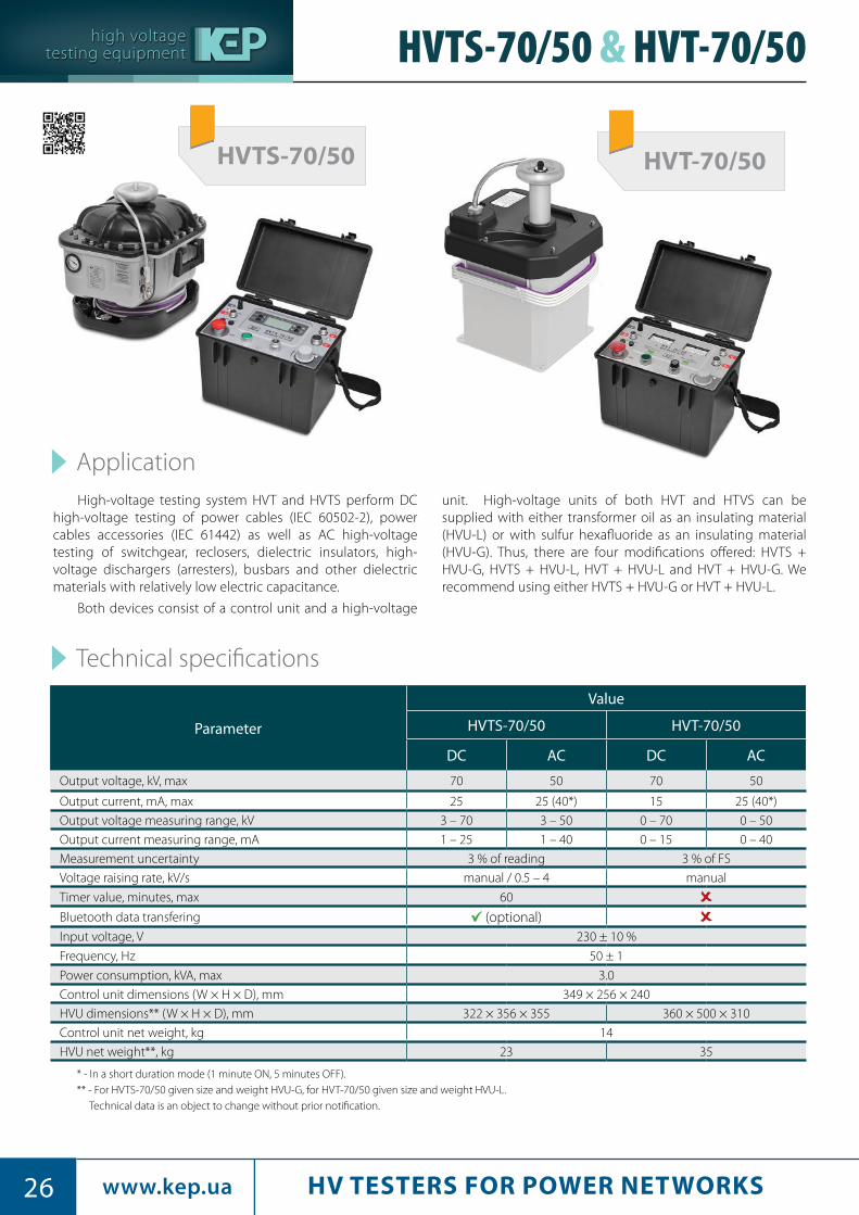
High-voltage testing system HVT and HVTS perform DC high-voltage testing of power cables (IEC 60502-2), power cables accessories (IEC 61442) as well as AC high-voltage testing of switchgear, reclosers, dielectric insulators, high-voltage dischargers (arresters), busbars and other dielectric materials with relatively low electric capacitance.
Both devices consist of a control unit and a high-voltage
unit. High-voltage units of both HVT and HTVS can be supplied with either transformer oil as an insulating material (HVU-L) or with sulfur hexafluoride as an insulating material (HVU-G). Thus, there are four modifications offered: HVTS + HVU-G, HVTS + HVU-L, HVT + HVU-L and HVT + HVU-G. We recommend using either HVTS + HVU-G or HVT + HVU-L.
Technical specifications
Application
Parameter
Value
HVTS-70/50 HVT-70/50
DC AC DC AC
Output voltage, kV, max 70 50 70 50
Output current, mA, max 25 25 (40*) 15 25 (40*)
Output voltage measuring range, kV 3 – 70 3 – 50 0 – 70 0 – 50
Output current measuring range, mA 1 – 25 1 – 40 0 – 15 0 – 40
Measurement uncertainty 3 % of reading 3 % of FS
Voltage raising rate, kV/s manual / 0.5 – 4 manual
Timer value, minutes, max 60
Bluetooth data transfering (optional)Input voltage, V 230 ± 10 %
Frequency, Hz 50 ± 1
Power consumption, kVA, max 3.0
Control unit dimensions (W × H × D), mm 349 × 256 × 240
HVU dimensions** (W × H × D), mm 322 × 356 × 355 360 × 500 × 310
Control unit net weight, kg 14
HVU net weight**, kg 23 35
* - In a short duration mode (1 minute ON, 5 minutes OFF).** - For HVTS-70/50 given size and weight HVU-G, for HVT-70/50 given size and weight HVU-L.
Technical data is an object to change without prior notification.
HVTS-70/50 & HVT-70/50
HVTS-70/50 HVT-70/50

high voltagetesting equipment
27HV TESTERS FOR POWER NETWORKS www.kep.ua
HVTS-70/50 control panel
Functional features
Control unit features HVTS HVT
High resistance to external environmental influences. Casing with firmly closing cover which prevents penetration of dust and moisture during the transportation and storageMobility. Supplied with a belt for easy transportation by a single personAdvanced protection and safety features. Emergency Stop button and grounding terminal on a front panel. Indication of the actual voltage on the output HV terminalAnalog indicators. Control panel with two analog indicators for voltage and current measurement *Overcurrent protection. Blocks output circuit if current exceeds the limitOvervoltage protection. Blocks output circuit if voltage exceeds the limitCE Compliant. Conforms to the EU Directives 2006/95/EC (LVD) and 2004/108/EC (EMC), which is proven by independent tests at TRaC laboratories, UKImproved precision. Ability to measure RMS values of both AC voltage and current irrespectively to the crest-factor (True-RMS) thus greatly reducing the crest factor errorsHigh-contrast graphical display. Ability to control and adjust the unit using a context menu which an operator can navigate by pressing keys located on both sides of display and reading the results on the display. Display indicates measurement and auxiliary information during test procedureAutomatic testing mode. Automatic and manual testing modes. In AUTO mode the unit raises the voltage at a pre-set rate to a pre-set voltage value, keeps the voltage on an object under test (OUT) for a certain time and then drops the voltage slowly down to zeroInternal memory for test results storage. Ability to save up to eight presets for the most frequently used test procedures. Ability to save measurement data historyAuxiliary protection. Blocking HVU-G output if insulating gas pressure is low or its temperature is high
High-Voltage unit features HVU-G HVU-L
External automatic. External shorting rod with a visible shorting indication. Ability to discharge OUT after voltage has been dropped down to zero by an operator without touching the High Voltage Unit.Auxiliary protection. Built-in pressure and temperature sensorsReduced weight and dimensions
* - graphic display shows two analog bars which are an emulation of an analog indicating scales.
HVT-70/50 control panel HVTS-70/50 conveyance carriage (optional)
HVTS-70/50 & HVT-70/50
You can also try to use it virtually from our web-site (Adobe Flash Player required)

high voltagetesting equipment
28 HV TESTERS FOR POWER NETWORKSwww.kep.ua
ApplicationThe High-power high-voltage testers of HVTS-
HP series are designed for testing an insulation of high-voltage cables and other non-liquid dielectric materials with both AC and DC voltage up to 140 kV.
Typically this series includes testers which have a test voltage 70 kV DC/50 kV AC 50 Hz and 100 kV DC/100 kV AC 50Hz. There are two common modifications for each model mentioned above which can bring output power value of 7.5 kVA and 17.5 kVA.
Any other special models, which have test voltages up to 250 kV with a power of up to 40 kVA are available on customer’s request.
Technical specifications
High-voltage insulation tester HVTS-HP
HVTS-HP control panel
ParameterHVTS-HP
70/55-7.5 (17.5)HVTS-HP
70/100-7.5 (17.5)HVTS-HP
100/100-7.5 (17.5)HVTS-HP
140/100-7,5 (17.5)
Output AC voltage, kV, max 55 100Output DC voltage, kV, max 70 100 140Output AC current, mA, max 130* (300*) 75* (175*)Output DC current, mA, max 90 (200) 30 (65) 40 (90) 55 (125)Output AC voltage measuring range, kV 3 – 55 3 – 100Output DC voltage measuring range, kV 3 – 70 3 – 100 3 – 140Output AC current measuring range, mA 1 – 130 (3 – 300) 1 – 75 (1 – 175)Output DC current measuring range, mA 1 – 90 (3 – 200) 1 – 30 (1 – 65) 1 – 40 (1 – 90) 1 – 55 (1 – 125)Measuring uncertainty, % 3 of readingInterface languages Russian, English, (Turkish, Polish and other – on request)Input voltage, V 230 ± 10 %Frequency, Hz 50 ± 1 (60 – on request)Output power, kVA, max 7.5 (17.5)
Parameters for a 17.5 kVA model of HVTS-HP are given in parenthesis.

high voltagetesting equipment
29HV TESTERS FOR POWER NETWORKS www.kep.ua
High-voltage insulation testerHVTS-HP
HVTS-HP high voltage unit
Transporting position Operating positionThe connectors for control unit connection
HVTS-HP control unit

high voltagetesting equipment
3030 www.kep.ua CIRCUIT BREAKERS TESTERS30
Automatic circuit breaker testers UPA-1 UPA-3
ApplicationAutomatic circuit breaker testers UPA are intended for
automatic AC current circuit breakers testing. The devices allow registering the values of the supplied current and timing the automatic circuit breaker switching interval.
UPA operate on the principle of varying the power in the primary circuit of the matching power transformer and, respectively, varying the output current, flowing through the
automatic circuit breaker under the test. Power regulation could be done either through an external voltage regulator (RNO or VR) or through a built-in thyristor controller.
All metrological characteristics (current and time measurement) are valid if RNO is used, i.e. if the exit signal waveform is stable (just as in other analogs).
AC voltage regulators from 20 A to 120 A are available
upon request
• RNO-VT-20 20A
• RNO-VT-40 40A
• RNO-VT-80 80A
• RNO-VT-120 120A
UPA-3(UPA-1)
Current source 3 kА(1 kА)
RNO-VT-20*
* - recommended voltage regulator for current UPA models (optional)
RNO-VT-20RNO-VT-40
UPA-10(UPA-6)
RNO-VT-80*

high voltagetesting equipment
3131www.kep.uaCIRCUIT BREAKERS TESTERS 31
UPA-6 UPA-10 UPA-16 UPA-20
Technical specifications
ParameterValue
UPA-1 UPA-3 UPA-6 UPA-10 UPA-16 UPA-20
Output current measuring range in mode “kA” (RMS), kA
one turn 0.1 – 1 1 – 3 1 – 6 1 – 9.99 3 – 16 3 – 20
two turns 0.05 – 0.5 0.5 – 1.5 – – 1.5 – 8 1.5 – 10
three turns 0.03 – 0.33 0.33 – 1 – – 1 – 5.33 1 – 6.67
four turns 0.025 – 0.25 0.25 – 0.75 – – 0.75 – 4 0.75 – 5
five turns 0.02 – 0.2 0.2 – 0.6 – – 0.6 – 3.2 0.6 – 4
Output current measuring range in mode “A” (RMS), A
one turn 10 – 100 100 – 1000 100 – 999 200 – 4000
two turns 5 – 50 50 – 500 – – 100 – 2000
three turns 3.3 – 33 33 – 330 – – 66.7 – 1333
four turns 2.5 – 25 25 – 250 – – 50 – 1000
five turns 2 – 20 20 – 200 – – 40 – 800
Measurement uncertainty (for A and kA), % 3 of FS
Circuit breaker switch off time measuring uncertainty*:
50 ms – 990 ms, ms ± 20
1 s – 7200 s** , % 3 of reading
Max. time of uninterrupted work at max. current, s 10
Input voltage, V 230 ± 10 % 230 V / 400 V ± 10 %
Frequency, Hz 50 ± 1
Power consumption, kVA, max 5.5 33 55 55
Control unit dimensions (W × H × D), mm 347 × 140 × 210542 × 360 × 200
660 × 985 × 480
Current source dimensions (W × H × D), mm 110 × 212 × 253 185 × 305 × 360
Control unit net weight, kg 347
110
Current source net weight, kg 16.7 56
UPA-16(UPA-20)
* - recommended voltage regulator for current UPA models (optional)
* The given measurement uncertainty are true when operating a UPA with VR.** The measurement of current feed duration over 10 s should be done at the current of not more than 1000 A. UPA-6, UPA-10 have 1 s - 990 s range.
RNO-VT-120*

high voltagetesting equipment
32 www.kep.ua32 OIL TESTERS
OLT-80A & OLT-80MOil testers
Oil testers are used for testing dielectric liquids with their breakdown voltage measuring. A-series of oil testers works automatically, according with selected standard, which are preloaded.
Both A and M series of oil testers bring out accurate and repeatable results of measured breakdown voltage. Fast high-voltage switch off time makes it possible to carry out test of dielectric liquids, which are easily destroyed under such influences.
The internal design of oil testers combined with a use of automatic high voltage breakers, cutting off supplied voltage if tester’s lid has been opened during the test, provide operator with high level of safety.
Testers are fully equipped and are ready for operation right after unpacking. They come with a test vessel (IEC 60156 – basic configuration) with VDE 0370 mushroom-shape electrodes. A gap between electrodes is easily regulated with a use of pass-no pass gauge, which comes in pack.
A-series provides with fully automatic test procedure according to selected standard (basically IEC 60156 and GOST 6581 settings are preloaded). It has a built-in printer which is able to print a test report after procedure is done. Test results are saved into non-volatile memory of oil tester. A PC-connectivity makes it easy to collect data from oil tester, save and store them as well as print a fulfilled report. Test voltage is being measured directly on electrodes. This fact combined with a true sine voltage shape (independent from supply voltage shape), increases repeatability and accuracy of measurements.
M-series provides operator with ultra-simplicity of operation. It doesn’t require any presets. All you need is pressing start button after a test vessel is loaded. Tester will show a breakdown voltage result immediately after breakdown occurs.
Test vessel for this series goes with magnetic stirrer, which stirs a liquid between two measurements.
Description
Application
M-Series
OnlineSimulator
A-Series
OLT-80M(OLT-90M)
(OLT-100M)
OLT-80A(OLT-90A)
(OLT-100A)

high voltagetesting equipment
33www.kep.ua 33OIL TESTERS
OLT-80A & OLT-80M Oil testers
Designed in accordance with IEC 61010 safety requirements.
Meets light industrial IEC 61326-1 Class B, CISPR 16-1, CISPR 16-2 and CISPR 22.
Safety and EMC compliance
Technical specifications
Parameter A-Series M-Series
Output AC voltage (symmetrical), OLT-80 / OLT-90 / OLT-100, kV RMS
80 / 90 / 100
Voltage resolution, kV 0.1
Measurement uncertainty 3 % of reading 3 % of FS
Output voltage rise rate, kV/s 2 ± 0.2 – basic (changes according to selected standard) 2 ± 0.2
Switch-off time on breakdown, µs < 5
Temperature measuring range, °C 5.0 – 50.0 N/A
Programmed test sequences
IEC 60156 (BS EN 60156, CEI EN 60156, NF EN 60156, UNE EN 60156, SABS EN 60156, PA SEV EN 60156) GOST 6581,ASTM D877 & ASTM D1816 (optional)
N/A
Electrodes“mushroom” type IEC 60156 – basic; ASTM D877, ASTM D1816 (optional)
Test vessel IEC 60156, 400 ml, 1.0 kg
Go/No-Go gauge width, mm2.45 / 2.55 – basic;
1, 2, 2.5, 4 (optional)
Display resolution128 × 64 dot matrix, monochrome with
backlight3 × 7-segment digits
Interface languages English, Russian N/A
Printer thermal line, 8 dots/mm, 384 dots/line N/A
Memory for results, cells 512 N/A
PC connectivity USB B-type N/A
Input voltage, V 230 ± 10% (basic), 110/120 – on request 230 ± 10%
Frequency, Hz 50 / 60 ± 1 50 ± 1
Power consumption OLT-80 / OLT-90 / OLT-100, VA, max
100 / 120 / 140
OLT-80 dimensions (W × H × D), mm 461 × 280 × 271 471 × 280 × 271
OLT-90 dimensions (W × H × D), mm 520 × 300 × 320 500 × 300 × 320
OLT-100 dimensions (W × H × D), mm 530 × 315 × 320 540 × 315 × 320
Net weight OLT-80 / OLT-90 / OLT-100, kg 21 / 25 / 30 23 / 27 / 32
OLT-80A in comparison with OLT-100A

high voltagetesting equipment
34 www.kep.ua34 OIL TESTERS
* - Addititional test vessels are avaible on request
Stirrer
Go/No-Go gauge
A-Series built-in printer
ComponentQuantity
A-series M-seriesOLT oil tester 1 1Test vessel* IEC 60156 with electrodes and cover
1 1
Go/No-Go gauge 1 1
Magnetic stirrer 1 N/A
Lifting stick for magnetic stirrer 1 N/AUSB cable (A-B type) 1 N/APower cord (C-type plug.) 1 1
Grounding cable 1 1
Software on USB flash-drive 1 N/A
Fuses (250V/3A) 2 2Paper roll (inside the printer) 1 N/A
User’s manual 1 1ISO/IEC 17025 calibration certificate (optional, on Customer’s request)
1 1
C-80 (C-100) calibration kit (optional) 1 1
Package contents
Lifting stick
A-Series: OLT-80A, OLT-90A, OLT-100A M-Series: OLT-80M, OLT-90M, OLT-100M
Test vessel(mushroom-type electrodes)
Test vessel(cylinder-type electrodes,
optional)
Test vessel(sphere-type electrodes,
optional)
OLT-80A & OLT-80MOil testers
high voltagetesting equipment
35www.kep.ua 35OIL TESTERS
Technical specifications
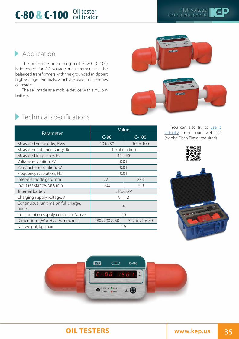
ApplicationThe reference measuring cell C-80 (C-100)
is intended for AC voltage measurement on the balanced transformers with the grounded midpoint high-voltage terminals, which are used in OLT-series oil testers.
The sell made as a mobile device with a built-in battery.
ParameterValue
C-80 C-100Measured voltage, kV, RMS 10 to 80 10 to 100Measurement uncertainty, % 1.0 of readingMeasured frequency, Hz 45 – 65Voltage resolution, kV 0.01Peak factor resolution, kV 0.01Frequency resolution, Hz 0.01Inter-electrode gap, mm 221 273Input resistance, MΩ, min 600 700Internal battery LiPO 3.7VCharging supply voltage, V 9 – 12Continuous run time on full charge, hours
4
Consumption supply current, mA, max 50Dimensions (W × H × D), mm, max 280 × 90 × 50 327 × 91 × 80Net weight, kg, max 1.5
You can also try to use it virtually from our web-site (Adobe Flash Player required)
C-80 & C-100 Oil tester calibrator

high voltagetesting equipment
36 www.kep.ua36 OIL TESTERS
ApplicationA digital automatic dissipation factor
measurement apparatus Tangens-3M is intended for taking measurements of the transformer oil dielectric dissipation factor according to IEC 60247 at 50 Hz frequency.
Technical specifications
YAPI-3 test cell specifications
Parameter Value
Dissipation factor (DF) measuring range0.0001 − 1.0000 (0.01% − 100 %)
DF measuring accuracy ± (0.03 DF + 0.0002)Resolution 0.00001Output AC voltage, V RMS 1940 – 2060Measuring uncertainty, % 2.5 of readingCapacitance measuring range, pF 5 − 30 Testing temperature, °С 90Temperature measuring accuracy, °С ± 1Measuring time for "Program 1"(measuring at 70 °С and 90 °С), minutes
35
Measuring time for "Program 2"(measuring at 70 °С, 80 °С and 90 °С on increasing temperature and measuring at 90 °С, 80 °С and 70 °С on decreasing temperature), minutes
85
Input voltage, V 230 ± 10 %Frequency, Hz 50 ± 1Power consumption, kVA, max 0.3Dimensions (W × H × D), mm 405 × 260 × 90Weight (incl. package), kg, max 10
Terminals count 3Volume, cm3 11 – 13AC voltage corresponding to electric field strength of 1 MV/m, kV RMS
2
The system measures:
• dissipation factor tgδ;• dielectric capacitivity ε;• capacitance С;• voltage applied to a measurement cell;• a transformer oil sample temperature.
YAPI-3
Digital automatic dissipation factor measurement apparatus Tangens-3М

high voltagetesting equipment
37www.kep.ua 37RESONANT TESTING SYSTEMS www.kep.ua
Resonance testers UIG are designed for testing high voltage objects such as generator stator windings, busbars, cables insulation, etc. with an AC voltage of an industrial frequency or with a rectified current voltage in semi-automatic and automatic modes.
UIG testers are developed based on the principle of parallel resonance in an electrical circuit in which an object under the test acts as an electrical capacitance (the stator winding of the generator, track, etc.), and where an automatic inductance changing is used for supporting the current resonance. For all voltage ranges, the resonance is maintained automatically.
Inductance change is done using a resonance reactor, which can have two structural variations.
The first option has a decreased initial value of inductance due to mechanical changes to the magnetic gap reactor. In the second option is based on changing the inductance of the bias magnetic DC reactor.
Using the current resonance effect enables a significant reduction of a power consumption (usually 40 times and more). Thus, it reduces voltage regulator power, a step-up transformer rated power as well allows for a smaller cross-section of cables.
The resonance testers UIG support performing full set of high-voltage tests for the high-power generators.
UIG testers are bespoke devices produced according to the individually client's requirements.
Application
RESONANT TESTING SYSTEMS UIG

high voltagetesting equipment
38 www.kep.ua38 RESONANT TESTING SYSTEMSwww.kep.ua
Resonance testers for testing hydraulic turbine, turbogenerators and cables
ApparatusOutput
power, kVA
Test object capacitance,
uF
Voltage, kVPlace where installedAC (with
resonance)DC (without resonance)
DC
UI-25/50/70-180 180 0.01 – 0.8 25 50 70 Ust-Khantaiskaya HPP, Russia
UI-15/225 2250.01 – 6
(6 @ 7.5 kV)15 – – CJSC Beltelekabel, Belarus
UIG-35/50/70-315 315 0.01 – 0.8 35 50 70 Dniester PSP, Ukraine
UIG-35/400 400 0.01 – 1 35 – – Boguchanskaya HPP, Ukraine
UIG-50-500 500 0.01 – 0.7 35 50 70 Rogunskaya HPP, Tajikistan
UIG-30/60/85-700 700 0.01 – 2.5 30 60 85 Voljskaya HPP, Russia
UIG-35/70/100-750 750 0.01 – 1.5 35 70 100 Sayano-Shushenskaya HPP, Russia
UIG-35/70/100-800 800 0.01 – 1.8 35 70 100 Krasnoyarskaya HPP, Russia
UIG-35/70/100-1400 1400 0.01 – 1.5 35 70 100 Sayano-Shushenskaya HPP, Russia
Apparatus comparison table
Generalized specifications
Parameter Value
Output AC voltage in stator winding test mode, kV, max 30 – 501
Output AC voltage in bus test mode, kV, max 60 – 100
Output DC voltage in leakage current test mode, kV 85 – 140
Output AC/DC current, A, max 6 – 45
Measurement uncertainty (specified from 10 % of range to 100 % of range), %
3
Output power, kVA, max 200 – 1500
Test object capacitance, µF, max 0.5 – 4
Duty cycle at full load (test / idle), minutes 20 / 40
Output test voltage rising speed (adjustible), kV/s 1
Input AC current, A 80 – 120
Input voltage, V 400 ± 10 %2
Frequency, Hz 50 ± 1
Power consumption, kVA 30 – 50
Typical dimensions (W × H × D), mm 1800 × 2200 × 1900
Weight, kg 1200 – 35001 - there are possible modifications with increased output voltage (up to 330 kV);2 - for low-power apparatus It is possible to have mains voltage 230 V ± 10 %;
UI-25/50/70-180
UIG-50-500
UIG-35/400

high voltagetesting equipment
39www.kep.ua 39RESONANT TESTING SYSTEMS RESONANT TESTING SYSTEMS www.kep.ua
Resonance testers for testinghydraulic turbines, turbogenerators and cables
UIG-35/70/100-300 UIG-35/70/100-300
UIG-35/70/100-300
high voltagetesting equipment
40 www.kep.ua40
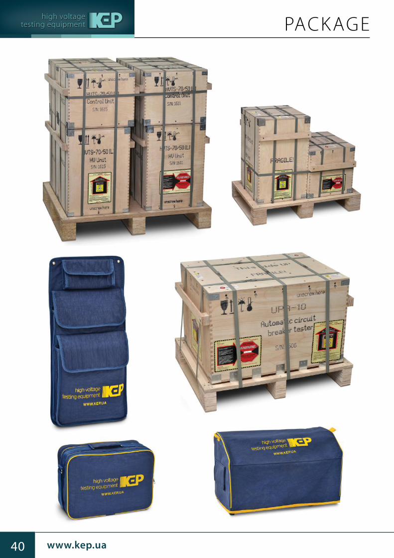
PACKAGE

high voltagetesting equipment
41www.kep.ua 41

high voltagetesting equipment
42 www.kep.ua42
DEALERSCHINA
PD Technologies Limited+852-3695-0998+852-3695-0999
[email protected] Kong , Block 1, Flat F, 16F., Kin Ho
Industrial Bldg., 14 Au Pui Wan Street, Shatin
EGYPT
Engineering Trade Office+2 (02) 3384-7711
[email protected], 6 Abd El Kawy Ahmed street - El
Mohandseen - 12411
INDIA
MTekpro Technologies Private Limited+91 (11) 4152-12-45
[email protected] Delhi - 110048, B-229, LGF, Greater
Kailash Part-1
INDONESIA
Pt. Sinergi Sinar Abadi+62 (813) 802-84622+62 (821) 227-06844
[email protected], Jl. Pancoran Timur III No.6 Perdatam Jakarta Selatan 12780
IRAK
Al Zaitoon Group Companies+ 00 (964)-790-333-0-354 [email protected]
Irak, Basra, Al Jazair Street
IRAN
Niroonamad Khorasan Company
+98 (51) 324-00-761 www.niroonamad.comMashhad, on the corner of 5th Kooshesh, down of 11th Sanat, High Technologies Industrial State
Protection Services Co.+98 (21) 8824-3403+98 (21) 8896-5140
[email protected], No.13, Alborz St., Baluchestan
St.,Gisha St.
KAZAKHSTAN
TOO "Technosila-Kazakhstan" (GK Energoskan) +7 (7172)-78-34-27 [email protected], str. Beybitshilik 14, office 402
RUSSIAN FEDERATION
ALFA-ENERGY Ltd.+7 (495) 505-76-70
[email protected], str. 1-st Radiatorskaya, 3
Electronpribor Ltd. +7 (495) 258-91-11+7 (903) 128-60-47
[email protected], str. Barskiye prudy, d. 1, of. 4
Energoskan Ltd.+7 (495) 268-02-90 [email protected], str. Akademika Koroleva, 13, office
839

high voltagetesting equipment
43www.kep.ua 43
DEALERSSOUTH AFRICA
NERM Applications and Testing (Pty) Ltd.
+27 (11) [email protected], 187 Dr Vosloo Road, N12 Business Park,
Gauteng, 1460
SOUTH KOREA
Altus Corporation+82 (0) 32-321-5075+82 (0) 32-321-5076
[email protected], RM 801-B, Richtown, 1080-1, Jung-
dong, Wonmi-gu Bucheon-city
Sam-Young Tech+82 (0) 32-324-2231 [email protected], 505 (Bugun Plaza, Sang-dong),
Giljuro77 beongil 61, Wonmi-gu, Bucheon-si
TURKEY
ELZ Enerji Elektrik Elektronik İnş. Malz. İth. San. ve Tic. Ltd. Şti +90 (312) 354-7030 [email protected], Saray Mah. 213. Sok. No: 3/A Kazan 06980
UZBEKISTAN
"Vodiy ulgurji sanoat" Ltd. +998 (91) 342-92-09+998 (93) 499-00-55
[email protected], str. Navoi, 7
VIE TNAM
Ha Long Inspection And Technical Service J.S.C.
+84 (4) [email protected], No.2, Quarter 46, Quan Hoa Ward,
Cau Giay District
Hitech International Equipment J.S.C.+84 (4) 8589-4552+84 (4) 4450-3265
[email protected], No 2, H4 Block 8, Van Phuc ward,
Ha Dong dist
Measuring And Testing Equipment Co., Ltd. +84 (4) 3719-8669+84 (4) 3719-8659
[email protected] Hanoi, 88 Au Co Street, Tay Ho Dist
Pacific Technology And Equipment Co., Ltd. (Patek)
+84 (8) [email protected] Chi Minh, 69/1A Truong Van Hai St, Tang Nhon
Phu B Ward, District 9
Services And Automation For Energy J.S.C.+84 (4) 6296-7703+84 (4) 6295-4359
[email protected], Room 807, 8FL, 315 Truong Chinh Building,
Thanh Xuan Ha Noi
Technology Transfer Group Corporation(TT-Group) +84 (4) 2-2249-599;
+84 (4) [email protected], No. 71/15, Do Quang Lane, Tran Duy Hung
Street, Trung Hoa Aven, Cau Giay District

high voltagetesting equipment
v3.1 en
Kharkovenergopribor Ltd.9, 3rd International str.,Kharkov, 61075, Ukraine
+380 57 393 1069
+380 67 576 2575
+380 50 304 4449
KEP Power Testing Ltd.28, Dorchester House, 8 Strand Drive, Richmond, TW9 4DX, United Kingdom
+44 (0) 780-96-38-478
www.kep.ua
HIGH VOLTAGE TESTING & MEASUREMENT EQUIPMENT CATALOG