Embed Size (px)
Citation preview

MULTILINGET-6555
Protective RelaysHigh Voltage Transmission Line
Protection with Single Pole Tripping and Reclosing
GE Power Management

CONTENTS
Page No.
INTRODUCTION . . . . . . . . . . . . . . . . . . . . . . . . . . . . . . . . . . . . . . . . . . . . . . . . . . . . . . . . . . . . . . .1
SINGLE AND SELECTIVE POLE TRIPPING AND RECLOSING . . . . . . . . . . . . . . . . . . . . . . . . . . .1
POWER TRANSFER VS. SYSTEM IMPEDANCE . . . . . . . . . . . . . . . . . . . . . . . . . . . . . . . . . . . . . . .2
INTEGRATED VS. SEPARATED SCHEMES . . . . . . . . . . . . . . . . . . . . . . . . . . . . . . . . . . . . . . . . . .7Separated Schemes . . . . . . . . . . . . . . . . . . . . . . . . . . . . . . . . . . . . . . . . . . . . . . . . . . . . .9Integrated Schemes . . . . . . . . . . . . . . . . . . . . . . . . . . . . . . . . . . . . . . . . . . . . . . . . . . . . .9Hybrid Schemes . . . . . . . . . . . . . . . . . . . . . . . . . . . . . . . . . . . . . . . . . . . . . . . . . . . . . . . .11
OTHER CONSIDERATIONS . . . . . . . . . . . . . . . . . . . . . . . . . . . . . . . . . . . . . . . . . . . . . . . . . . . . .11Line Side vs. Bus Side Potentials . . . . . . . . . . . . . . . . . . . . . . . . . . . . . . . . . . . . . . . . . . .11Tripping vs. Blocking Schemes . . . . . . . . . . . . . . . . . . . . . . . . . . . . . . . . . . . . . . . . . . . . .12Evolving Faults . . . . . . . . . . . . . . . . . . . . . . . . . . . . . . . . . . . . . . . . . . . . . . . . . . . . . . . .12Line Construction – Fault Resistance . . . . . . . . . . . . . . . . . . . . . . . . . . . . . . . . . . . . . . . .13Open Pole Operation . . . . . . . . . . . . . . . . . . . . . . . . . . . . . . . . . . . . . . . . . . . . . . . . . . . .13Circuit Breaker Failure Back-up Protection . . . . . . . . . . . . . . . . . . . . . . . . . . . . . . . . . . . .13Sensitivity . . . . . . . . . . . . . . . . . . . . . . . . . . . . . . . . . . . . . . . . . . . . . . . . . . . . . . . . . . . .13Security . . . . . . . . . . . . . . . . . . . . . . . . . . . . . . . . . . . . . . . . . . . . . . . . . . . . . . . . . . . . . . .14Relay Transient Behavior . . . . . . . . . . . . . . . . . . . . . . . . . . . . . . . . . . . . . . . . . . . . . . . . .14Series Compensated Lines . . . . . . . . . . . . . . . . . . . . . . . . . . . . . . . . . . . . . . . . . . . . . . .14
CONCLUSIONS . . . . . . . . . . . . . . . . . . . . . . . . . . . . . . . . . . . . . . . . . . . . . . . . . . . . . . . . . . . . . .15
APPENDIX I . . . . . . . . . . . . . . . . . . . . . . . . . . . . . . . . . . . . . . . . . . . . . . . . . . . . . . . . . . . . . . . . .16
APPENDIX II . . . . . . . . . . . . . . . . . . . . . . . . . . . . . . . . . . . . . . . . . . . . . . . . . . . . . . . . . . . . . . . . . .17
APPENDIX lll . . . . . . . . . . . . . . . . . . . . . . . . . . . . . . . . . . . . . . . . . . . . . . . . . . . . . . . . . . . . . . . . .18
APPENDIX IV . . . . . . . . . . . . . . . . . . . . . . . . . . . . . . . . . . . . . . . . . . . . . . . . . . . . . . . . . . . . . . . .19

1
INTRODUCTION
In recent years, the increasing constructioncosts brought on by inflation have imposedeconomic restrictions on many electric light andpower companies, and forced them to intensifytheir search for reductions in capital investmentand operating expenses. Faced with thecontinuing demand for more and more power inan environmentalist era, many operatingcompanies are seeking, among other things, ameans for supplying reliable power with fewertransmission lines and hence reduced capitalinvestment. Since the 1960s, we have seentransmission line voltages climb from 345kV to 500 kV and 765kV, with plans for voltages in the 1100-1500 kV range. Series capacitorcompensation has been employed as well as dctransmission to improve capital return, and nowattention is moving toward the application ofsingle and/or selective pole tripping ontransmission lines with and without seriescompensation.
SINGLE AND SELECTIVE POLETRIPPING AND RECLOSING
A relay protection scheme that provides forsingle pole tripping and reclosing is one that,after it detects a fault and establishes thattripping should take place, will trip only thefaulted phase on single-line-to-ground faultsand all three phases on all multi-phase faults. Insuch schemes automatic reclosing is alwaysemployed to reclose in the event of a single poletrip and sometimes also for three-phase trips.However, this latter operation is usually optionalby selector switch in the field. In general, singlepole tripping schemes perform as follows:
1. When a single phase-to-ground fault occurson an energized transmission line the faultedphase is tripped and automatically reclosedafter a suitable dead time. If the fault iscleared everything resets. If the fault is still on
the line when the pole is reclosed, all threepoles are tripped and no further reclosingtakes place.
2. When a multi-phase fault of any kind appearson an energized transmission line all threepoles are tripped. At this point, depending onhow the scheme is programmed, the breakerscould be locked out or, after a suitable deadtime, reclosed into the line. In the latter case.if the fault is gone, everything resets. If thefault is still present, all three poles trip and nofurther reclosing takes place.
3. When energizing a dead line by control switchor supervisory control, if any kind of fault ispresent on the line, three pole tripping takesplace and there is no automatic reclosing.
A protective relaying scheme that employsselective pole tripping would trip only thefaulted phase or phases and leave the unfaultedphase or phases in service. Thus, it would trip allthree poles for a three phase fault. It would tripthe two faulted phases for a double-phase-to-ground fault; it would trip only the faulted phaseon a single-phase-to-ground fault; and finally ona phase-to-phase fault it would trip the twofaulted phases.
It is interesting to note that there has beensome discussion and consideration given to amodified selective pole tripping scheme thatwould perform as noted above, with the oneexception that on phase-to-phase faults onlyone of the two faulted phases would be trippedto clear the fault. With regard to this latterproposal, the objection has always been raisedthat such an approach would require one pole ofa breaker to interrupt against 1.73 times ratedphase-to-neutral voltage. This is outside thenormal standard requirements for circuitbreakers and could contribute to a significantlyhigher probability of failure to interrupt.

2
Because of little or no experience with selectiveor modified selective pole tripping, there is nodata on how it is used. However, it is anticipatedthat single shot reclosing would be used for allfaults with the possible exception of 3-phasefaults. In any case, three phase tripping and noreclosing would prevail when closing into afault.
Also, because of little or no experience withselective pole tripping schemes, beforeselecting such a scheme, studies should bemade to ascertain whether any unusual effectssuch as resonance or overvoltages could resultfrom having only one pole closed.
POWER TRANSFER VS. SYSTEMIMPEDANCE
Single or selective pole tripping schemes areusually considered for one of the following reasons:
a) To specifically increase the availability of anisolated generating station that is connectedto the load center via only one or two threephase transmission lines.
b) To generally increase the reliability of a meshtransmission system on a second or thirdcontingency basis.
The extent to which bath single pole andselective pole tripping can increase thereliability of a transmission system depends onthe configuration of the system. The increase inreliability is obtained because tripping of one ortwo phases does not introduce as muchadditional impedance into the transmissionsystem as does tripping three phases. Thus, thesystem tends to be more stable.
If one considers a simplified power systemconsisting of two sources interconnected by a
transmission line, the three phase powertransfer across the system is given by thefollowing equation:
P =EXEY Sin δ (1)
X
where: P = Real power transfer in wattsfrom X to Y.
EX = The equivalent transmissionsystem line-to-line voltage involts at the X end of the system
EY = The equivalent transmissionsystem line-to-line voltage involts at the Y end of the system.(Here assumed equal to EX)
X = The equivalent system reactancein ohms referred to transmissionsystem voltage between the twosources EX and EY
δ = The angle by which the voltageEX leads EY.
If a system is to be reliable it must be relativelystable during abnormal conditions (faults, linesout of service, etc.) as well as during normalconditions. Equation 1 above indicates that themaximum power which can flow across thesystem is
Pmax. =E2
(2)X
This, the steady state stability limit, occurs at δ = 90 degrees. The relative stability of a givensystem similar to that of Figure 1 for differentconditions of faults and open phases can beevaluated by means of equation 1 above.
If we assume that the voltages EX and EY areconstant voltages behind the transientreactances of the two sources, and X is the sumof the line and machine reactances, then for agiven system reactance (X), the angle (δ)between the two voltages is directly related to

3
the power flow. For a given power flow, a higherreactance (X), will result in a greater angle δ. Thebigger the angle δ the less stable is the system.Thus, for any given required power transferacross the system, the lower the reactancebetween the points of transfer, the more stablethe system. Single and selective pole trippinghelp to keep this reactance low between theinstant when a fault is cleared (by opening lessthan all three phases) and the instant when theopen phases are reclosed.
In order to provide some appreciation for therelative advantages of single and selective poletripping over three pole tripping, a systemconsisting of two parallel high voltagetransmission lines interconnecting two largesystems was constructed in Figure 1 andanalyzed in Appendices l, II, and III, and IV.
From Figure 1 it will be noted that the positivesequence impedance of the two lines wasassumed as 0.6 ohms per mile which is a normalvalue for EHV construction. The ratio of zerosequence to positive sequence impedance ofthe lines was selected as 2.5 which is a ratherlow value for most EHV circuits. The twoequivalent system (X and Y) impedances wereassumed to have zero sequence to positive
sequence ratios of 1. This is a reasonableassumption since system impedances arecomprised of generators and transformers aswell as lines. The zero sequence impedance of aunit type generator transformer installationwould be in the order of 25 to 30 percent of thepositive sequence impedance during transientconditions.
The equivalent power transfer impedances forthe system of Figure 1 were evaluated inAppendices l, II, and III for various normal andabnormal system conditions as noted in thesecond column of Table I. In the calculations itwas assumed that all impedances were purereactance. While this is obviously not the case,the error introduced will not affect theconclusions in any significant way. The thirdcolumn of Table I indicates the appendix andequation where these impedances werecalculated. The calculations were based on each500 kV line being 100 miles long and the X andY systems being equivalent to 25 miles and 10miles of (positive sequence) transmission lineimpedance respectively. The fault location wasassumed to be in the middle of one line.
If in the system of Figure 1 the normal load flowis 1,500 megawatts from system Y to system X

4
divided over the two lines, then the normalangle across the system for Case 1 in Table I,would be obtained from:
P =EXEY Sin δ
X
1,500 x 106 =(500)2 x 10⁶
Sin δ51
Sin δ = 0.306δ = 17.8 degrees
For the other conditions of Table I, the anglesrequired to transmit these same 1,500megawatts under steady state conditions aregiven in the fourth column of the Table.
It is interesting to note from Table I that thesystem appears to be quite capable oftransmitting the 1500 megawatts continuouslyfor all cases except for the very last where only
one single phase was connecting the twosystems. The fact that cases 2 and 3 yieldexactly the same results is coincidental andresults accidentally from the parametersselected for the system. However, it is generallythe case that the ability of the system totransmit power through a single phase-to-ground fault in the middle of a long line is notvastly different than it is for the condition ofhaving one phase open.
While the above analysis provides a measure ofrelative stability for the different conditions itdoes not indicate definitely whether or not anyof the fault or open phase conditions would bestable in the transition period (transientstability). Appendix IV utilizes the “equal area”criteria to develop a simple, conservative meansfor evaluating the transient stability of thesecases. No calculations are indicated but it may
be shown by substituting the values of δ andZXY in the equations of Appendix IV that allcases are stable except for Case 8 which is acondition that could result when selective poletripping is employed. Because of theconservative nature of the approach of AppendixIV, Case 8 may in fact be stable but it wouldrequire a more comprehensive study toevaluate.
Probably a classical case for the application ofsingle and selective pole tripping is that wherean isolated generator or generating station isconnected to the system load center over onesingle transmission line. A reasonable exampleof such an application would be a 1,000 MW unittype generator connected through 100 miles of500kV transmission line to a system with anequivalent impedance equal to about 10 miles of500kV line. The characteristics of the line areassumed to be the 0.6 and 1.5 ohms per mile forthe positive and zero sequence reactancesrespectively. The generator positive sequencetransient reactance was assumed as 28 percent
5

and the negative sequence reactance as 20percent. The unit transformer was assumed tohave a positive and zero sequence reactance of10 percent with all impedances on a 1,000 MVAbase.
Table II gives the results of steady statecalculations similar to those used to establishthe values in Table I. In this case the singlephase-to-ground fault was assumed to be at thegenerator end of the line which is the worst casefor this system. From Table II it will be notedthat the system could not transmit the 1,000megawatts continuously during a phase-to-ground fault or for the case with two phasesopen. While it can transmit this power with only
one phase open, a transient analysis based onAppendix IV indicates a marginal situation.However, because of the conservative nature ofthese calculations, it is anticipated that thissystem could survive a single phase-to-groundfault that is cleared in several cycles by openingonly the faulted phase. On the other hand it isquestionable whether it could withstand adouble-phase-to-ground fault and the switchingof two phases.
It is interesting to note that, had the ratio of zerosequence to positive sequence line impedancebeen assumed equal to three, (a more normalratio than 2.5 at EHV), the results would haveindicated single line to ground faults to result insomewhat lower power transfer impedance,while open conductors would have producedhigher values for otherwise similar conditions.
The two simple studies discussed above, inaddition to other complete studies made overthe years, lead to the following generalconclusions regarding transmission line faults:
a) The ability to transfer power during a faultdecreases as the fault moves closer to asource or receiving terminal.
6

7
b) The ability to transfer power during a faultdecreases as the severity of the faultincreases from single-phase-to-ground, tophase-to-phase, to double-phase-to-ground,to three-phase.
c) The ability to transmit power over a transmissionline decreases as more phases are open.
d) The ability to transfer power increases for anyfault or open phase(s) as the number of tielines increases.
e) While not apparent from the Tables, it can beshown that for series compensated lines, theability to transfer power with two poles openbecomes much more difficult relative to the casewith one pole open than it is for ordinary lines.This is the case because for this condition thenegative and zero sequence networks areconnected in series (see Appendix II and Figure7) and because series capacitor compensation ismuch more effective in the negative sequencenetwork than it is in the zero sequence network.
In the total consideration of the type of schemeto select, the following points should beevaluated against the cost and complexities ofthe different schemes:
1) Single pole and selective pole trippingschemes offer the greatest gain to systemstability when only one tie line exists. Whereonly two tie lines exist it is reasonable toassume that one could be out of service whena fault occurs on the second line. Thus, somesort of single or selective pole trippingscheme could provide benefits comparable tothose where only one line exists. However, asthe number of ties increase beyond two, thestatistical advantages of single and selectivepole tripping fall off rapidly.
2) Single-phase-to-ground faults are very muchmore prevalent than phase-to-phase and
double-phase-to-ground faults.
3) Operation of a single tie with only one phaseclosed (as would be the case with selectivepole tripping during the dead time beforereclosing and after tripping two poles for adouble line to ground fault) results in a ratherunstable system. This, in practice, may not beany better than with all three poles beingtripped, so that selective pole tripping mayoffer no advantage over single pole tripping.
4) A modified selective pole tripping schemethat initiates tripping of only one phase for aphase-to-phase fault may overstress thecircuit breaker.
5) Because the ability of the system to transmitpower is very nearly the same for one phaseopen as it is for a single-phase-to-groundfault, and because the system must be able toride through reclosing dead time with at leastone pole open, extra high speed clearing ofsingle-phase-to-ground faults does notappear to be a requirement for stability inthose applications where single pole trippingis of value.
INTEGRATED VS. SEPARATEDSCHEMES
Single pole tripping schemes can be constructedin many different ways utilizing different typesof devices. However, the basic approaches maybe divided into two categories, “IntegratedSchemes” and “Separated Schemes”.
It is obvious that any single pole (or selectivepole) tripping scheme must make two basicdeterminations:
(a) Whether or not the fault is in the trip zone
(b) Which phase or phases are faulted.

In the case of (b) above, a single pole trippingscheme needs to determine whether it is amulti-phase fault or a single phase fault and inthe event of a single-phase-to-ground fault itmust establish which phase is faulted. On theother hand, a selective pole tripping schememust establish which phase or phases arefaulted for all types of faults.
An Integrated Single Pole (or Selective Pole)Tripping Scheme utilizes the same measuringfunctions to perform both (a) and (b) abovewhile a Separated Scheme would use one set offunctions to establish (a) and a separate set todetermine (b).
If one opts for an integrated scheme, then theselection of the measuring units is restricted tothose that can determine which phase or phasesare faulted, as well as whether the fault isinternal or external. For example, an integratedscheme could not satisfactorily employ zerosequence directional overcurrent relays forground fault protection because in themselvesthese ground relays could not determine whichof the three phases were faulted. A betterselection would be three single phasedirectional ground distance relays.
If a selective pole rather than a single poletripping scheme, is under consideration and if itis to be an integrated scheme, then the phasefault relays cannot consist of only onepolyphase device for all three pairs of phases,because this type of device cannot by itselfascertain which pair of phases is faulted. A moresuitable approach would be to use three singlephase units having directional ohmcharacteristics. A rather direct approach to anintegrated scheme is to use separate phasecomparison schemes for each individual phase.Such an approach, termed segregated phasecomparison, could be used for selective as wellas single pole tripping.
While other examples could be cited, thosealready mentioned make it clear that withregard to single or selective pole tripping, thereis an interdependence between the nature of thescheme and the type of measuring functionsrequired.
8

9
SEPARATED SCHEMES
Separated schemes will employ separatedevices called Phase Selectors in addition to theregular complement of protection. For example,if it is desired to utilize a directional comparisonblocking scheme to protect a line that willemploy single pole tripping, then the standardcomplement of relays for a directionalcomparison blocking scheme would be used inaddition to the separate phase selectors. Thedirectional comparison scheme woulddetermine whether or not to trip while thephase selectors would route the trip signal tothe proper pole or poles. If, on the other hand, itwas a phase comparison scheme that wasdesired, the same phase selector devices couldbe employed with standard phase comparisonscheme. In any case, however, three electricallyseparate pairs of trip outputs are required tofacilitate independent pole tripping of twocircuit breakers.
Figure 10 illustrates a separated single poletripping scheme that is operating in apermissive overreaching transferred trippingmode. The measuring functions (MT/Ø) andMT/GRD) are symbolic of any suitable set ofstandard directional phase and ground(distance) relays. The determination of whetherthe fault is internal or external is made in theupper part of this figure in the traditionalmanner. The phase (MT/Ø) and ground(MT/GRD) functions are set so that they can seeany fault on the protected lines operates to keythe local transmitter to its TRIP frequency viaOR1. The receipt of an output TRIP signal fromthe local receiver concurrent with the outputfrom OR1 produces an output from AND1. Anoutput from AND1 indicates an internal fault.
Concurrently, the Faulted Phase Selectorfunction must determine which phase or phasesare faulted and produce the associated outputs.The logic in the phase selector would be such
that for any fault other than a single-phase-to-ground fault it would produce a three-phaseoutput. For a single-phase-to-ground fault itwould produce an output associated with thefaulted phase. Thus, for a single-phase-to-ground fault only one of OR2, OR3, or OR4would produce an output to its respective AND.The second output to these AND’s would comefrom AND1 indicating an internal fault. Theoutput from one of these AND’s would then tripthe proper single phase. For any multiphasefault, the three-phase output from the phaseselector would energize all three OR’s and henceAND2, AND3, and AND4, to trip all three poles.
It should be recognized that the phase selectorin the single pole tripping scheme describedabove needs only to distinguish between multi-phase faults and single-phase-to-ground faults,and in the latter case to ascertain which phase isfaulted. In the case of selective pole schemesthe phase selector in addition would be requiredto determine the exact type of multi-phase fault.Such an additional requirement could increasethe complexity of this device by a substantialfactor without providing any significantadditional system integrity in many, if not all,cases.
The separated approach to single or selectivepole tripping permits a great deal of flexibility inthe selection of a protective scheme and thetype of measuring functions that could be used.This makes it easier to provide primary andback-up protection that operate in differentmodes and use different measuring functions.The basic disadvantage of a separated schemeis that it requires some additional measuringfunctions to perform the phase selection.
INTEGRATED SCHEMES
As opposed to separated schemes, integratedschemes use the same measuring functions todetermine which phase or phases to trip as are

used to establish whether the fault is internal orexternal to the zone of protection. A simplifiedfunctional representation of such a schemeoperating in a permissive overreaching transferredtripping mode is illustrated in Figure 11.
This diagram indicates three individual single-phase directional ground distance relays (MTG)and three directional phase distance relays (MT).If this arrangement is to perform properly then itis necessary that the MTG ground measuringfunctions be selective among themselves sothat for any single phase-to-ground fault onlythe faulted phase unit operates. For any multi-phase fault one or more of the phase MT unitsmust operate. These same MT and MTGfunctions also determine, in conjunction withthe channel, whether the fault is internal orexternal.
The operation of the scheme is such that whena fault in the trip direction occurs, one of the MTor MTG units operates to produce an outputfrom OR1 or OR2 which in turn results in anoutput from OR3. This output from OR3 keys thelocal transmitter to the TRIP frequency, and it
also provides one of the inputs to AND1. If thefault is internal, the remote end of the line willbe sending a TRIP frequency signal which willproduce a TRIP output from the local receiver.This TRIP output provides the second input toAND1 which then produces an output toindicate a desire to trip. This desire to trip signalis fed to ANDs 2 through 5 and depending onwhich measuring unit or units detected the faulteither one pole or all three poles would betripped.
If a selective tripping scheme is desired it wouldbe necessary to separate the MT phase trippingfunctions so that only the pairs of phases thatare faulted are actually tripped.
Another integrated single pole tripping schemeif functionally illustrated in Figure 12. Thisscheme operates in a phase comparison mode,utilizing three segregated phase comparisonfunctions, one per phase. Each phase has itsown fault detector (FD) and squaring amplifier(SQ. AMP.) as well as its own transmitter andreceiver. The scheme utilizes standard phasecomparison techniques except for the fact thateach of the three phase comparisons is made onthe basis of single phase currents.
10
11
Referring to Figure 12, when a fault involving phaseA occurs the associated fault detector (FD) picks upas does the squaring amplifier (SQ. AMP.). Thisresults in AND1 producing half cycle outputs whichare in phase with the positive half cycles of thephase A current. This produces half cycle keying ofthe transmitter to the TRIP frequency andsimultaneous half cycle inputs to AND2. If the faultis internal to the protected zone, the local receiverwill be producing TRIP outputs during the samehalf cycles as a result of the remote transmitterbeing keyed by its associated FD and SQ. AMP.functions. The output from the local receiversupplies the second input AND2. If these twoinputs to AND2 are coincident for threemilliseconds or more it indicates that the phase Acurrents entering both ends of the line are less thanabout 120 degrees out of phase and the fault mustbe internal. This produces a trip output to Phase A.
If the fault were to involve more than one phase,then more than one phase comparison wouldtake place simultaneously. If the fault wereinternal, trip outputs would be channeled to allthree phases via the 2-OR-MORE logic. Two ormore inputs to this logic produce an output thattrips all three poles.
In this case, if selective pole tripping is desired,the 2-OR-MORE logic would be eliminated.
While both Figures 11 and 12 representintegrated schemes there are two very apparentdifferences:
1) The scheme of Figure 11 involves only onechannel while that of Figure 12 requires three.
2) The scheme of Figure 11 is capable ofproviding three-pole second zone back-upprotection for remote bus faults by theaddition of a timer after OR3. The scheme ofFigure 12 cannot provide this back-upprotection because phase comparison is atrue differential type of scheme.
HYBRID SCHEMES
If in the equipment indicated as “Faulted PhaseSelector” in the separated scheme of Figure 10there are some functions required that aresimilar to those used in the fault detectingequipment, a hybrid scheme can be used. As theterm implies, a hybrid scheme is one that hassome device or devices dedicated to phaseselection, other devices dedicated to faultdetection and still other devices that arecommon to both functions. This kind ofarrangement would in general be moreeconomical than a separated scheme. However,it would generally restrict the type of measuringfunctions used.
OTHER CONSIDERATIONS
The above discussion of the different schemes,along with Figures 10 through 12, are verygeneral in nature and cover only the broadestconcepts. There are a number of significantdetails that can affect the suitability of anygiven scheme for any given application. Someof these are enumerated and discussed below.
Line Side vs. Bus Side Potentials
Because single and selective pole trippingschemes must perform properly and detectfaults that occur or evolve during the time thatone or more poles are open, the location of thepotential supply to the relays can be important.If one phase of a transmission line is open atboth ends while the other two phases areenergized the “dead” phase voltage does not goto zero. The voltage on this open and unfaultedphase will have some magnitude and angle thatdepends on:
a) Whether or not the line is transposed, and ifit is not transposed, which phase is open.

12
b) Whether or not shunt reactors are employed,and if they are, the amount of compensationthey afford and the configuration of thereactors.
c) Load flow in the two intact phases.
When the potential transducers are located onthe bus side of the circuit breaker, the threephase voltages tend to stay relatively wellbalanced when one, or even two phases, areopen.
While the phase comparison scheme illustratedin Figure 12 is unaffected by these conditionsbecause no potential supply is required, allschemes using relays that require potentialmust be designed to mitigate the effects of anypossible misoperation during the time that oneor more poles are open. This requirement tendsto make distance relaying schemes utilizing lineside potentials somewhat more complex thanthose that employ bus side potentials.
Tripping vs. Blocking Schemes
In traditional blocking type schemes noblocking signal is sent in the quiescent state. Onthe other hand, in permissive tripping andunblocking schemes, the blocking signal isnormally sent in the quiescent state. In theselatter types of schemes it is usually necessary toprovide some means for tripping a circuitbreaker when picking up a dead line that isfaulted. Traditionally in three pole schemes thisis accomplished by means of circuit breakerauxiliary switches or sensitive current detectorsthat key the transmitters to the unblock or tripfrequency when the associated circuit breaker isopen. Another approach would be to utilize a“Line Pick-up Scheme” that permits tripping onthe operation of a fault detector alone, when acircuit breaker is closed or reclosed to pick up adead line.
In general this same situation exists whensingle pole and selective pole schemes are usedin unblocking or permissive modes. However,when only one single channel is used, as in theschemes of Figures 10 and 11, more detailedconsideration must be given to this aspect ofthe design, because opening any one polewould key the transmitter while the other twopoles are closed and carrying load. This couldresult in a false trip in the unlikely event that anearby external fault were to occur during thetime one pole were open unless provisions areincluded to mitigate this situation. In generalthis is not a consideration in the segregatedphase comparison scheme of Figure 12 becauseit utilizes one communication channel perphase. It is also not a consideration in blockingschemes because no blocking signal is sent inthe quiescent state.
Evolving Faults
An evolving fault is one that starts as a single-phase-to-ground fault and then involvesadditional phases during the time that the initialfault is being cleared or during the dead time ofthe original faulted phase.
Single pole and selective pole schemes shouldprovide some means for detecting and clearingevolving faults. The method for accomplishingthis will depend on a number of differentfactors. If the scheme employed is thesegregated phase comparison scheme of Figure12, the ability to detect evolving faults tends tocome naturally, because each phase is protectedon an individual basis. On the other hand, inschemes that utilize relays that require potentialsupplies, it is necessary, in the design of thelogic, to consider the types of measuringfunctions employed, and whether or not lineside potential sources are used in order to insurethe desired performance.

13
Line Construction-Fault Resistance
In general, if ground distance relays are to beused in a protective scheme it is important torecognize that they do have some limitationwith regards to high fault resistances. Suchrelays tend to have difficulties with single-phase-to-ground faults initiated by trees orbrush fires. However, because most single orselective pole tripping schemes are used onlong or medium length lines this problem issomewhat mitigated by the large reach settingsrequired to protect them. Where such conditionscan exist, or where the line construction is suchthat no shield wires exist and high tower footingresistance to ground is prevalent, carefulconsideration must be given before grounddistance relays are applied. High ground faultresistance, in combination with heavy loadtransfer, can make it difficult for the segregatedphase comparison scheme of Figure 12 to detectsingle-phase-to-ground faults.
Open Pole Operation
When one or two poles of a transmission lineare open, an asymmetrical condition exists onthe system that results in negative and zerosequence current flow throughout the systemwhich in turn produce negative and zerosequence voltages throughout the system.Negative and zero sequence directional relayslocated at the terminals of a transmission linethat is operating with one or two open phaseswill receive voltages and currents that indicateto the relays at both terminals the impressionthat an internal fault exists. If sufficientmagnitude of current is flowing, such devicescould produce continuous trip outputs duringthe time that one or more poles are open. Tosimilar relays located at both ends of a parallelline, the condition resembles an external fault.Other similar relays located elsewhere on thesystem may see the condition as either aninternal or an external fault.
In any case, schemes that employ zero ornegative sequence relays must be designedwith these points in mind because thecontinuous output of a tripping relay cancontinue to activate the circuit breaker back upprotection during the time that one or two polesare open, and could also result in a re-trip whenthe open pole(s) is reclosed.
Circuit Breaker Failure Back-up Protection
In single pole and selective pole trippingschemes, it is necessary to consider factorsregarding circuit breaker failure back-upprotection that are somewhat different fromthose involved in three pole tripping schemes.
If a circuit breaker pole fails to interrupt whenattempting a single pole operation, it isnecessary to trip all three poles of the failedbreaker plus all the back-up circuit breakers. Inthis regard the operation is no different than anythree pole scheme. However, if a circuit breakereffects a successful single pole trip, during thedead time of the faulted phase, the two goodphases are still carrying current. Thus, single andselective pole tripping schemes must utilizesegregated pole current detectors that must, inthe logic of the overall scheme, be associatedindividually with the devices that determinewhich phase is faulted. With such anarrangement the scheme will not operateincorrectly as a result of current continuing toflow in the healthy phases of a line during thetime that one pole is open.
The approach to the scheme of current breakerfailure back-up protection must be coordinatedwith the basic line protection scheme selected.
Sensitivity
In general, the sensitivity of the protectionscheme to all kinds of faults will depend on thetype of measuring functions used. For example,

14
zero or negative sequence relays can be moresensitive to very high resistance ground faultsthan ground distance relays or segregatedphase comparison relays. However, if negativeor zero sequence relays are used, some otherdevice will have to establish which phase isfaulted. The ability of distance relays toaccommodate high resistance faults willincrease with reach settings as will their overallsensitivities. On the other hand, segregatedphase comparison schemes, because the faultdetectors may have to be set above full loadcurrent in order to prevent continuous phasecomparison, tend to become less sensitive onlong, heavily loaded lines.
It is also interesting to note that blockingschemes can trip sequentially on weak infeedfrom one terminal while unblocking andpermissive tripping schemes, unless modified,require both ends to see the fault before eitherend can trip.
Security
In any protection scheme there is always acompromise between security anddependability. While both these measures ofperformance are affected by such factors asoperating errors, faulty channels and couplingequipment, improper applications, incorrect CTand PT connections as well as basic relayperformance, it is safe to say that false tripstend to be considerably more prevalent than dofailures to trip.
The use of two separate sets of protection(primary and back-up) tends to reduce overallsecurity and increase overall dependability.Thus, it is important to use a scheme (orschemes) that is inherently most secure. As ageneral rule secure schemes will be those with:
a) simple application rules
b) simple installation and test requirements
c) a minimum of protection equipment
d) a minimum of channel equipment.
There is probably no one scheme that isuniversally applicable and capable of providing100 percent performance. When selecting asingle pole or selective pole tripping scheme,consideration should be given to the selectionof a relatively simple scheme that may initiatean occasional three pole trip for single-phase-to-ground faults, as against, a relatively complexscheme that theoretically will never trip morethan the faulted phase(s).
Relay Transient Behavior
While the degree may vary, all measuringfunctions have a transient response to faultsthat is different from their steady stateresponse. High speed relays operate during thetime that the power system is in a transientstate. Thus, the important characteristics of anyprotection scheme are those that relate to thetransient conditions on the power systemimmediately after a fault occurs, during thepresence of the fault, and immediately after thefault is cleared. These characteristics can onlybe completely evaluated by extensive testing onan analog model of the power system. Only inthis way is it practical to apply thousands offaults of different initiation angles and locationsfor different system conditions and observe theactual relay performance.
Series Compensated Lines
In general, the considerations governing theprotection of series compensated lines tend tobe more complex than those for ordinaryuncompensated circuits. The addition of singleor selective pole tripping to this protection canfurther complicate the situation.

15
On the surface it appears that segregated phasecomparison schemes are naturally suited forsuch applications. However, schemes usingdistance and directional fault detectors withadditional phase selectors may prove to besuperior in performance while still maintaining ahigh level of security as a result of using onlyone channel.
CONCLUSIONS
Single and selective pole tripping schemes maybe used to maintain a desired level of systemintegrity while minimizing transmission lineexpenditures. In general, these schemes will bemost effective on those portions of the systemwhere relatively few interconnections exist.While selective pole tripping may superficiallyappear to provide more margin than single poleschemes in the preservation of system stability,it seems unlikely that in those actualapplications where single pole tripping iswarranted that selective pole tripping willprovide any significant advantages.

16
This appendix evaluates the equivalentimpedance between the two system (X & Y)sources of Figure 1 for the conditions of bathlines in service and normal, and for the sameconditions except a phase-to-ground fault in themiddle of Line W.
Assume a 500kV system as in Figure 1 withLines E and W each 100 miles in length. Assumethat the equivalent impedance of System X isequal to that of 25 miles of 500kV line and thatof System Y is equal to 10 miles of line. Inaddition let the zero sequence and positivesequence system impedances be equal.
Thus:
ZL1 = 100 x 0.6 = 60 ohmsZL0 = 100 x 1.5 = 150 ohmsZX1 = 25 x 0.6 = 15 ohmsZX0 = 25 x 0.6 = 15 ohmsZY1 = 10 x 0.6 = 6 ohmsZY0 = 10 x 0.6 = 6 ohms
With the system intact the effective impedancebetween busses P&R is:
ZL1 = 30 ohms I-12
The effective impedance between the source inSystem X and the source in System Y is:
ZX1 +ZL1 + ZY1 = 15 + 30 + 6 = 51 ohms I-22
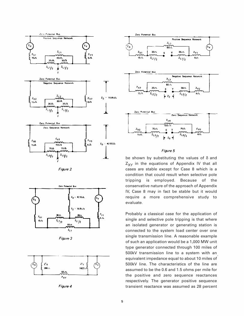
Consider now a single phase-to-ground fault inthe middle of line W. During the time that thefault is on this line the system sequenceimpedances are as indicated in Figure 2assuming that the negative sequenceimpedance is equal to the positive sequenceimpedance.
The equivalent impedance between point F andthe zero potential bus in the negative sequencenetwork can be shown to be:
Z2 = 19.85 ohms I-3
The equivalent impedance between point F andthe zero potential bus in the zero sequencenetwork can be shown to be:
Z0 = 42.55 ohms I-4
The equivalent circuit that determines thestability of the system is the combination of thethree networks of Figure 2 as illustrated inFigure 3. Figure 4 illustrates the reduction (bysuccessive wye-delta and delta-wyetransformations) of Figure 3 to yield theimpedance ZXY which determines the loadtransfer capability of the system as indicated bythe following equation:
P =EXEY Sin δ I-5XXY
where:P is the real power transfer across the
system from X to Y.
δ is the angle by which EX leads EY. XXYis the reactive component of ZXY andis essentially equal in magnitude toZXY.
It will be noted from Figure 4 that with the singlephase-to-ground fault in Line B the equivalentimpedance across the entire system is:
ZXY = 60 ohms I-6
This is only about 20 percent higher than undernormal conditions as can be noted fromequation I-2 above.
APPENDIX I

17
This appendix evaluates the equivalentimpedance between the two system (X and Y)sources of Figure 1 for the conditions of one andtwo phases open on Line W with Line E inservice.
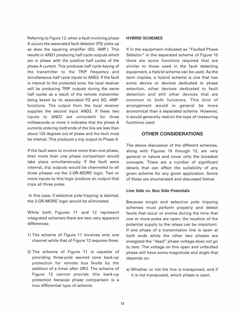
Assume the same 500kV system as in Figure 1and as considered in Appendix I except nowassume that instead of being faulted, both linesE and W are in service except that one or twophases of Line W are open. The individualsequence networks for these conditions areillustrated in Figure 5.
For the case of only one conductor open thenetworks are interconnected by connectingpoints S in all three networks together and
connecting points T in all three networkstogether. This results in the arrangementillustrated in Figure 6. For this condition theequivalent impedance that controls the powertransfer is:
ZXY = 60 ohms II-1
Figure 7 depicts the case for two conductorsopen on Line W. For this case the zero sequenceand negative sequence networks are in serieswith each other and inserted between points Sand T in the positive sequence network. Thisresults in an impedance:
ZXY = 71 ohms II-2
APPENDIX II
18
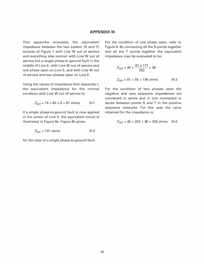
This appendix evaluates the equivalentimpedance between the two system (X and Y)sources of Figure 1 with Line W out of serviceand everything else normal, with Line W out ofservice but a single phase-to ground fault in themiddle of Line E, with Line W out of service andone phase open on Line E, and with Line W outof service and two phases open on Line E.
Using the values of impedance from Appendix I,the equivalent impedance for the normalcondition with Line W out of service is:
ZXY = 15 + 60 + 6 = 81 ohms III-1
If a single phase-to-ground fault is now appliedin the center of Line E, the equivalent circuit isillustrated in Figure 8a. Figure 8b gives:
ZXY = 107 ohms III-2
for the case of a single phase-to-ground fault.
For the condition of one phase open, refer toFigure 9. By connecting all the S points togetherand all the T points together the equivalentimpedance may be evaluated to be:
ZXY = 45 +81 x 171
+ 36252
ZXY = 81 + 55 = 136 ohms III-3
For the condition of two phases open thenegative and zero sequence impedances areconnected in series and in turn connected inseries between points S and T in the positivesequence networks. For this case the valueobtained for the impedance is:
ZXY = 45 + 252 + 36 = 333 ohms III-4
APPENDIX III
19
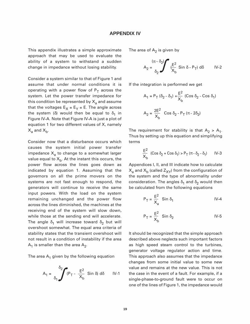
This appendix illustrates a simple approximateapproach that may be used to evaluate theability of a system to withstand a suddenchange in impedance without losing stability.
Consider a system similar to that of Figure 1 andassume that under normal conditions it isoperating with a power flow of PT across thesystem. Let the power transfer impedance forthis condition be represented by Xa and assumethat the voltages EX = EY = E. The angle acrossthe system (δ) would then be equal to δ1 inFigure IV-A. Note that Figure IV-A is just a plot ofequation 1 for two different values of X, namelyXa and Xb.
Consider now that a disturbance occurs whichcauses the system initial power transferimpedance Xa to change to a somewhat largervalue equal to Xb. At the instant this occurs, thepower flow across the lines goes down asindicated by equation 1. Assuming that thegovernors on all the prime movers on thesystems are not fast enough to respond, thegenerators will continue to receive the sameinput powers. With the load on the systemremaining unchanged and the power flowacross the lines diminished, the machines at thereceiving end of the system will slow down,while those at the sending end will accelerate.The angle δ1 will increase toward δ2 but willovershoot somewhat. The equal area criteria ofstability states that the transient overshoot willnot result in a condition of instability if the areaA1 is smaller than the area A2.
The area A1 given by the following equation
δ2A1 =
δ1
(PT - E2
Sin δ) dδ IV-1Xb
The area of A2 is given by
(π - δ2)
A2 = δ2
(E2
Sin δ - PT) dδ IV-2Xb
If the integration is performed we get
A1 = PT (δ2 - δ1) +E2
(Cos δ2 - Cos δ1)Xb
A2 =2E2
Cos δ2 - PT (π - 2δ2)Xb
The requirement for stability is that A2 > A1.Thus by setting up this equation and simplifyingterms
E2(Cos δ2 + Cos δ1) > PT (π - δ2 - δ1) IV-3
Xb
Appendices I, II, and III indicate how to calculateXa and Xb (called ZXY) from the configuration ofthe system and the type of abnormality underconsideration. The angles δ1 and δ2 would thenbe calculated from the following equations
PT =E2
Sin δ1 IV-4Xa
PT =E2
Sin δ2 IV-5Xb
It should be recognized that the simple approachdescribed above neglects such important factorsas high speed steam control to the turbines,generator voltage regulator action and time.This approach also assumes that the impedancechanges from some initial value to some newvalue and remains at the new value. This is notthe case in the event of a fault. For example, if asingle-phase-to-ground fault were to occur onone of the lines of Figure 1, the impedance would
APPENDIX IV
∫
∫

20
change to, and remain at, some new value forabout three cycles until the faulted phase wascleared, at which time, the impedance wouldchange to the value that exists with one poleopen. It would remain at that value for about 20 – 30 cycles, at which time, the impedancewould return to its initial value when the breakeris automatically reclosed.
Thus, there are three (rather than two) powercurves that should be considered for the case offaults. However, it is assumed that the durationof the fault is short compared to the duration ofthe open phase, and if it is further consideredthat the power transfer impedance (ZXY) for thecondition of a single phase-to-ground fault is nottoo different from that for the condition of onepole open, then it is a reasonable approximation
to assume the system goes from a normal statedirectly to a condition of one pole open in thissimplified approach.
In any event, the approach is quite conservativebecause it assumes that the system remains withthe one pole open until stability is either lost orestablished. In an actual situation, the open polemay very well be reclosed long before the angleswings to (π - δ2) As indicated in Figure IV-B thisyields an area A2 which is significantly greaterthan A1. Exactly where in time and angle (δ3) thechange would take place can be evaluated by acomplete transient stability study. However, if thesimple approach outlined in this Appendixindicates a stable situation it will be stable in reallife. On the other hand a system found to beunstable by this method may in fact be stable.

21
where:
E = The transmission system voltage involts
PT = The power transfer across the systemin watts prior to the disturbance
Xa = The power transfer reactance of thesystem before the disturbance
Xb = The power transfer reactance of thesystem after the disturbance
δ1 = Angle in radians across the systemprior to the disturbance
δ2 = Angle in radians across the systemafter the disturbance.
Figure IV-B

�����������������������������������������������������������������������������������������*(�3RZHU�0DQDJHPHQW
215 Anderson AvenueMarkham, OntarioCanada L6E 1B3Tel: (905) 294-6222Fax: (905) 201-2098www.GEindustrial.com/pm