Embed Size (px)
Citation preview
High Voltage Use in Environmental Application
VLK ROSTISLAV*1, MILAN KRASL *2 Department of Electrical Engineering and Ecology*1
Department of Electromechanics and Power Electronics*2
University of West Bohemia in Pilsen Univerzitni 8, 306 14, Plzen
CZECH REPUBLIC http://www.zcu.cz
Abstract: - This paper deals with a possibility of central energy supply instead of single supply of electrostatic filter cells designated for cleaning of the air in the street tunnels. It was observed the influence of an electric discharge between high voltage metal electrodes of the air electrostatic filter cell in connection with operating voltage of other filter cells parallel-connected. Key-Words: - Electrical precipitator, Power supply, Voltage drop, High voltage.
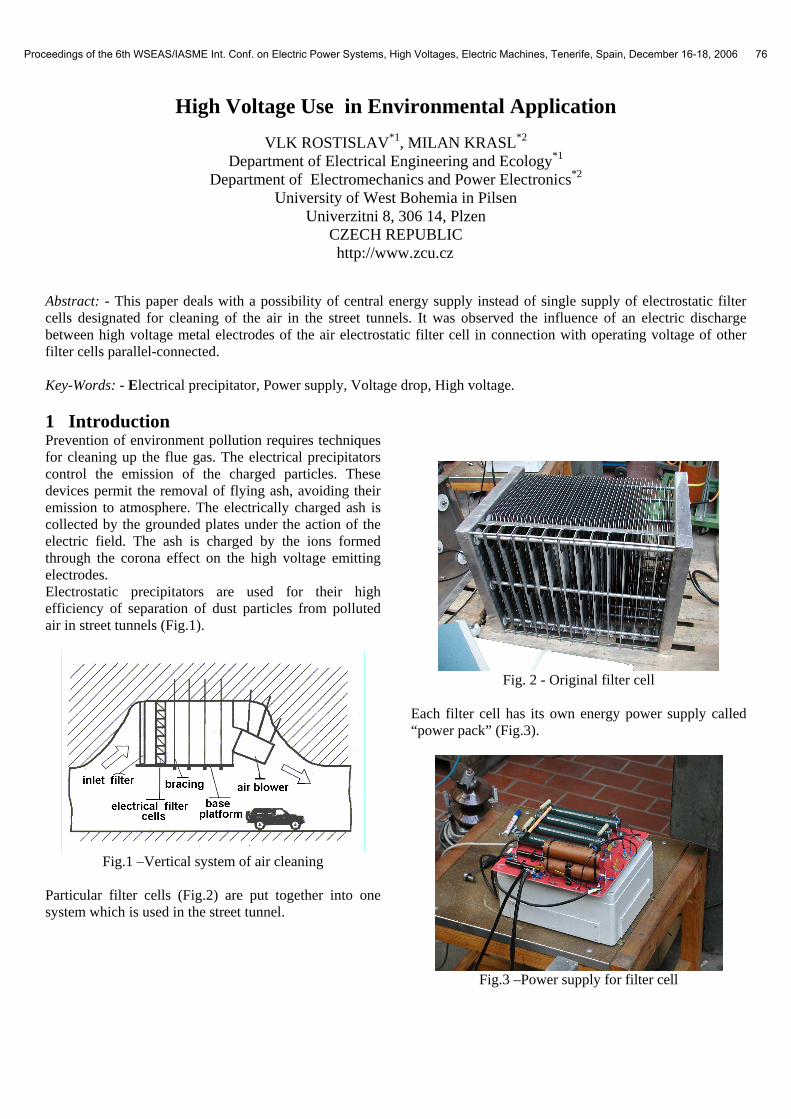
1 Introduction Prevention of environment pollution requires techniques for cleaning up the flue gas. The electrical precipitators control the emission of the charged particles. These devices permit the removal of flying ash, avoiding their emission to atmosphere. The electrically charged ash is collected by the grounded plates under the action of the electric field. The ash is charged by the ions formed through the corona effect on the high voltage emitting electrodes. Electrostatic precipitators are used for their high efficiency of separation of dust particles from polluted air in street tunnels (Fig.1).
Fig.1 –Vertical system of air cleaning
Particular filter cells (Fig.2) are put together into one system which is used in the street tunnel.
Fig. 2 - Original filter cell
Each filter cell has its own energy power supply called “power pack” (Fig.3).
Fig.3 –Power supply for filter cell
Proceedings of the 6th WSEAS/IASME Int. Conf. on Electric Power Systems, High Voltages, Electric Machines, Tenerife, Spain, December 16-18, 2006 76
Due to huge system of the high voltage distribution cables for energy power supply of all filter cells there does exist demand to reduce number of high voltage cables in mentioned application. This reduction could be executed by means of modification of power supply.
2 Standard connection of power supply source and filter cell Each particular filter cell has its own energy power supply. Energy power supply called “power pack” consists of high voltage transformer, high voltage diods, high voltage capacitors and resistors [1]. This “Power pack” is connected to ionization chamber of the filter cell according to schematic diagram (Fig.4).
Fig.4 –Schematic diagram of power supply
There are approximately hundred and more of filter cells in the street tunnel there. During installation of a such large system it is a big demand on precision of high voltage cable mounting. Due to that costs of the high voltage cables for the power supply of filter cells are high there was an idea to modify energy power supply system. That idea is based on the reduction of number of high voltage “power packs”. It means that one energy source (“power pack”) should supply more then one filter cell. 2.1 Modification of energy power supply of
filter cell As it was mentioned above the idea of new connection of energy power supply is to reduce number of the high voltage transformers in the whole system. Schematic diagram of modified connection of power supply of filter cells is shown on Fig.5
Fig.5 – Schematic diagram of modification of power supply
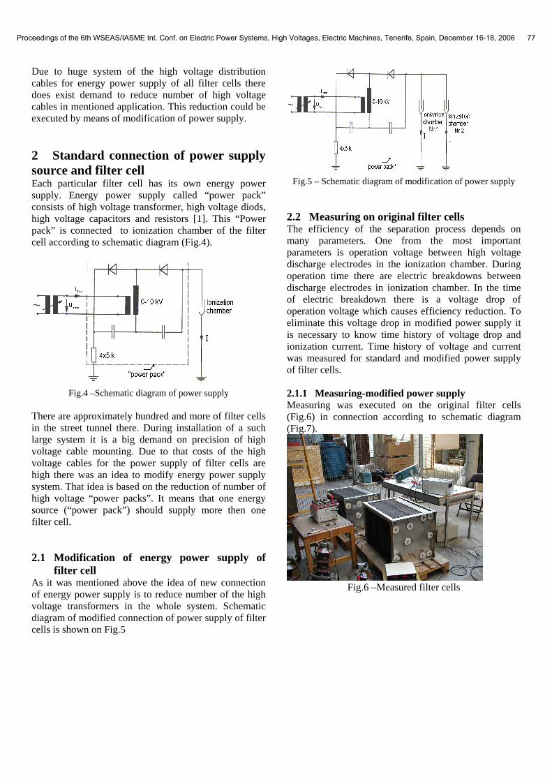
2.2 Measuring on original filter cells The efficiency of the separation process depends on many parameters. One from the most important parameters is operation voltage between high voltage discharge electrodes in the ionization chamber. During operation time there are electric breakdowns between discharge electrodes in ionization chamber. In the time of electric breakdown there is a voltage drop of operation voltage which causes efficiency reduction. To eliminate this voltage drop in modified power supply it is necessary to know time history of voltage drop and ionization current. Time history of voltage and current was measured for standard and modified power supply of filter cells. 2.1.1 Measuring-modified power supply Measuring was executed on the original filter cells (Fig.6) in connection according to schematic diagram (Fig.7).
Fig.6 –Measured filter cells
Proceedings of the 6th WSEAS/IASME Int. Conf. on Electric Power Systems, High Voltages, Electric Machines, Tenerife, Spain, December 16-18, 2006 77
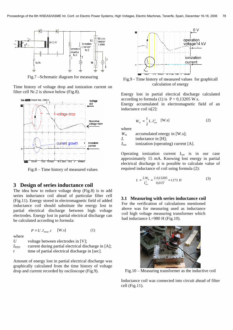
Fig.7 –Schematic diagram for measuring
Time history of voltage drop and ionization current on filter cell Nr.2 is shown below (Fig.8).
Fig.8 – Time history of measured values
3 Design of series inductance coil The idea how to reduce voltage drop (Fig.8) is to add series inductance coil ahead of particular filter cell (Fig.11). Energy stored in electromagnetic field of added inductance coil should substitute the energy lost in partial electrical discharge between high voltage electrodes. Energy lost in partial electrical discharge can be calculated according to formula:
tIUP PED ..= [W.s] (1)
where U voltage between electrodes in [V]; IPED current during partial electrical discharge in [A]; t time of partial electrical discharge in [sec]. Amount of energy lost in partial electrical discharge was graphically calculated from the time history of voltage drop and current recorded by osciloscope (Fig.9).
Fig.9 - Time history of measured values for graphicall
calculation of energy Energy lost in partial elecrical discharge calculated according to formula (1) is P = 0,13205 W.s. Energy accumulated in electromagnetic field of an inductance coil is[2]:
2.2
1ionm ILW = [W.s] (2)
where Wm accumulated energy in [W.s]; L inductance in [H]; I ion ionization (operating) current [A]. Operating ionization current I ion is in our case approximately 15 mA. Knowing lost energy in partial electrical discharge it is possible to calculate value of required inductance of coil using formula (2):
HI
WL
ion
m 1173015,0
13205,0.2.222
=== (3)
3.1 Measuring with series inductance coil For the verification of calculations mentioned above was for measuring used as inductance coil high voltage measuring transformer which had inductance L=980 H (Fig.10).
Fig.10 – Measuring transformer as the inductive coil
Inductance coil was connected into circuit ahead of filter cell (Fig.11).
Proceedings of the 6th WSEAS/IASME Int. Conf. on Electric Power Systems, High Voltages, Electric Machines, Tenerife, Spain, December 16-18, 2006 78
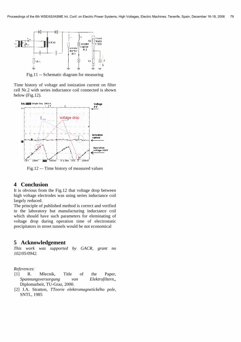
Fig.11 -- Schematic diagram for measuring
Time history of voltage and ionization current on filter cell Nr.2 with series inductance coil connected is shown below (Fig.12).
Fig.12 -– Time history of measured values
4 Conclusion It is obvious from the Fig.12 that voltage drop between high voltage electrodes was using series inductance coil largely reduced. The principle of published method is correct and verified in the laboratory but manufacturing inductance coil which should have such parameters for eleminating of voltage drop during operation time of electrostatic precipitators in street tunnels would be not economical
5 Acknowledgement This work was supported by GACR, grant no 102/05/0942. References: [1] R. Mlecnik, Title of the Paper,
Spannungsversorgung von Elektrofiltern,, Diplomarbeit, TU-Graz, 2000.
[2] J.A. Stratton, TTeorie elektromagnetického pole, SNTL, 1985
Proceedings of the 6th WSEAS/IASME Int. Conf. on Electric Power Systems, High Voltages, Electric Machines, Tenerife, Spain, December 16-18, 2006 79