Embed Size (px)
Citation preview
Thin Solid Films 518 (2010) 3169–3176
Contents lists available at ScienceDirect
Thin Solid Films
j ourna l homepage: www.e lsev ie r.com/ locate / ts f
Highly-ordered mesoporous titania thin films prepared via surfactant assembly onconductive indium–tin-oxide/glass substrate and its optical properties
Hiroshi Uchida a,⁎, Mehul N. Patel b, R. Alan May c, Gaurav Gupta b, Keith J. Stevenson c, Keith P. Johnston b
a Department of Materials and Life Sciences, Sophia University, Tokyo 102-8554, Japanb Department of Chemical Engineering, Center for Nano- and Molecular Science and Technology, Texas Materials Institute, The University of Texas at Austin, Austin, TX 78712, USAc Department of Chemistry and Biochemistry, Center for Nano- and Molecular Science and Technology, Texas Materials Institute, The University of Texas at Austin, Austin, TX 78712, USA
⁎ Corresponding author. Tel.: +81 3 3238 3375; fax:E-mail address: [email protected] (H. Uchida).
0040-6090/$ – see front matter © 2009 Elsevier B.V. Aldoi:10.1016/j.tsf.2009.08.050
a b s t r a c t
a r t i c l e i n f oArticle history:Received 4 February 2009Received in revised form 6 July 2009Accepted 31 August 2009Available online 8 September 2009
Keywords:Titanium oxideSol–gel coatingSelf assemblyMesoporous materialsEllipsometryOptical properties
Highly ordered mesoporous titanium dioxide (titania, TiO2) thin films on indium–tin-oxide (ITO) coatedglass were prepared via a Pluronic (P123) block copolymer template and a hydrophilic TiO2 buffer layer. Thecontraction of the 3D hexagonal array of P123 micelles upon calcination merges the titania domains on theTiO2 buffer layer to form mesoporous films with a mesochannel diameter of approximately 10 nm and apore-to-pore distance of 10 nm. The mesoporous titania films on TiO2-buffered ITO/glass featured an inversemesospace with a hexagonally-ordered structure, whereas the films formed without a TiO2 buffer layer had adisordered microstructure with submicron cracks because of non-uniform water condensation on thehydrophobic ITO/glass surface. The density of the mesoporous film was 83% that of a bulk TiO2 film. Theoptical band gap of the mesoporous titania thin film was approximately 3.4 eV, larger than that fornonporous anatase TiO2 (~3.2 eV), suggesting that the nanoscopic grain size leads to an increase in the bandgap due to weak quantum confinement effects. The ability to form highly-ordered mesoporous titania filmson electrically conductive and transparent substrates offers the potential for facile fabrication of high surfacearea semiconductive films with small diffusion lengths for optoelectronics applications.
+81 3 3238 3361.
l rights reserved.
© 2009 Elsevier B.V. All rights reserved.
1. Introduction
In recent decades, mesoporous oxide materials with highly-ordered channel/matrix structures have received extensive attentionbecause of their prospective applications, e.g., sensors, catalystsupports, gas storage devices, micro- or nano-sized membranes forseparations, biomedical templates, etc. [1–8]. In addition, thin filmmesoporous oxide materials on flat substrates are an importantcomponent for manufacturing products in microelectronics andoptoelectronics including flat panel devices and integrated circuits[9–11]. Mesoporous titania is of particular interest for use inphotovoltaic cells, optical waveguides, optical or chemical sensors,and optical catalysts [12–17] because it is a semiconductor withdesirable photochemical and optical properties. Many of theseapplications require that the mesoporous material be patterned on atransparent conductive substrate such as indium–tin-oxide (ITO)coated glass. We recognize that a highly-ordered mesochannelstructure, i.e., the combination of mesochannels and matrices whichare aligned with each other in certain periodic geometries, with afeature size of ~100 nm (submicron) could be an important factor forimproving device performance in these applications.
Generally, ordered mesoporous oxide films may be fabricated viasol–gel synthesis templated by a supramolecular assembly of organicsurfactants. In the case of mesoporous titania films, inorganic titaniumprecursors such as alkoxides or chlorides are dispersed in a water/ethanol/surfactant (cationic or non-ionic) system to prepare a sol–gelcoating solution. The film is prepared by spin- or dip-coating of thesolution, followed by aging, and calcination of the film. Themorphologyof the mesochannel structure is primarily determined by the configu-ration of the self-assembled organic surfactants in these systems, whichmay change during the sol–gel reaction according to the nature andvolume ratio of inorganic, water, and surfactant components [18–25].Recently, the Stucky group has synthesized mesoporous titania andsilica films with cubic, hexagonal, or lamellar mesochannels usingvariousblock copolymer surfactants as templates [26,27], aswell as bulksamples of various metal oxides [28].
Grosso and Sanchez have evaluated the channel structure inmesoporous titania films by X-ray analysis and provided detailedreports characterizing the self-assembly mechanism of surfactanttemplates [29–34]. Additionally, they proposed and demonstrated theapplication of these films as solar cells and electrochemical sensors[35,36].
Wu et al. used a surfactant templated sol–gel technique to preparearrays of titania nanopillarswith 3D hexagonalmesochannel assemblieson silicon substrates [37]. An ordered 3D hexagonal array of blockcopolymer micelles with hydrophobic cores was formed in the film
3170 H. Uchida et al. / Thin Solid Films 518 (2010) 3169–3176
template during the titania gel formation. Upon heating, shrinkage ofthe titania gel mesostructure perpendicular to the substrate connectsthe block copolymer micelles and densifies the titania domains to forman inverse mesospace in the form of titania nanopillars. Theseperpendicularly-oriented mesochannels are preferred to disordered orparallel aligned channels because they are more accessible to masstransport of various adsorbates or species undergoing chemicalreaction [38,39]. Given the hygroscopic nature of titania gels, theamount of water absorbed during the film aging process after coatingthe sol–gel precursor has a profound effect on the morphology of theself-assembled mesochannel structure [32,40–42]. Higher relativehumidity (RH) results in excessively swollen and wet films due to theabsorption of water, and conversely, lower RH results in disorderedmesochannels which may have a vermicular or quasi-hexagonalstructure.
The objective of this study is to form a thin film of highly-orderedmesoporous titania on a conductive and transparent ITO/glass substrate.ITO/glass substrates are frequently used for optical and optoelectronicapplications because they are transparent throughout the visiblewavelength region and are electronically conductive. However, ITOhas a much lower surface energy compared to a silicon (Si) wafer.Relative to Si, poor wetting of the lower surface energy ITO/glasssubstrate may limit the ordering of the block copolymer template andthus the organization of the mesochannel structure [41,42]. During theaging process, adsorbed water spreads evenly at the interface betweenthe titania gel and substrate if the substrate surface is hydrophilic. For ahydrophobic surface, water condenses to form liquid droplets at theinterface resulting in non-uniform, swollen and/or distorted structureson the substrate. A hydrophilic surface such as Si wafer (surface energy:0.14 J/m2, with native oxide layer [43]) is favorable for formation ofordered surfactant micelles resulting in a mesochannel structure uponcalcination [29], whereas surface modification is required to preparehighly-ordered mesoporous films on a relatively hydrophobic surfacesuch as glass (surface energy: ~0.06–0.08 [44,45]) and ITO-coated glass(surface energy: ~0.05 J/m2 [46]). Also, hydrophilic surfaces are moreamenable to the film coating because hydrophobic surfaces may repelthe coating solution resulting in a non-uniform film coating. Toovercome these issues the surface of the ITO/glass substrates wasmodified with an ultrathin TiO2 buffer layer in order to increase thesurface wettability and to facilitate the ordering of mesochannels. TiO2
has a high surface energy (~0.280–0.380 J/m2) and can be developedinto a superhydrophilic surface based on photocatalytic reaction [47–52]. Thus, the TiO2 buffer layer overcomes the problems of non-uniformor swollen/distorted structures on ITO/glass substrates. Furthermore, itappears that the TiO2 buffer layer does not form an electrically-insulating heterojunction with the mesoporous titania film. Using thistechnique we produced mesoporous titania films with a hexagonalclose-packed mesochannel structure on TiO2-buffered ITO/glass sub-strates utilizing self-assembly of non-ionic triblock copolymer micelles.The effect of temperature during the aging process was studied tomanipulate the reaction kinetics as well as the self-assembly process ofthe surfactant. The morphology of the mesoporous titania films wasstudied using scanning electron microscopy (SEM) and small angle X-ray scattering (SAXS). The porous fraction and optical band gap of thefilms were determined using a combination of spectroscopic ellipso-metry (SE) and transmission measurements.
2. Experimental details
2.1. Materials
Titanium (IV) isopropoxide [Ti(O·i-C3H7)4] (97%) was purchasedfrom Sigma-Aldrich, and hydrochloric acid [HCl] (35.5%), ethanol[C2H5OH] (Absolute 200 proof) and 2-propanol [(CH3)2CHOH] (99.9%)were purchased from Fisher Scientific. Non-ionic triblock copolymersurfactant Pluronic P123 [poly-(ethyleneoxide)poly-(propyleneoxide)
poly-(ethylene oxide) EO20–PO70–EO20] was kindly supplied by BASF.These chemicals were used as received. Water (H2O) was double-distilled and deionized. Si wafers with mirror-polished (100) surfacewere obtained fromWafer World, Inc. ITO/glass slides (resistance: 15–25Ω, ITO layer thickness: 60–100 nm) were purchased from DeltaTechnologies, Limited.
2.2. Preparation of substrates
Si wafers and ITO/glasswere cut into 1×1 cm2 sections, rinsed usingethanol, and then blown dry in a N2 flow. A TiO2-buffer layerwas coatedon the ITO/glass substrate by chemical solution deposition. A solutionprepared from 0.03 g of Ti(O·i-C3H7)4 and 10 cm3 of 2-propanol wascoated on the ITO/glass substrate by dip-coating with a withdrawalspeed of approximately 6.0 cm/min, followed by heat treatment at200 °C for 5 min in air. The buffer layer was also coated on a polyestersheet for SAXS analysis.
2.3. Preparation of mesoporous titania films
Mesoporous titania films were prepared by self-assembly of theP123 block copolymer surfactant in sol–gel solution [27,37]. 1.05 g ofTi(O·i-C3H7)4 was hydrolyzed using 0.74 g of HCl under stirring for10 min at room temperature. The hydrolyzed sol wasmixedwith 0.2 gof P123 surfactant dissolved in 3.0 g of ethanol under stirring for15 min at room temperature. The resulting solution was spin-coatedon the substrates at a rate of 8000 rpm for 1 min, followed by aging for2 days at either −5 °C or 25 °C under a controlled humidity of 45–55%. The samples were finally calcined using a tube furnace at 400 °Cfor 4 h in air with a heating rate of 1.0 °C/min to remove the blockcopolymer template and enhance the inorganic framework betweenTi and O atoms.
2.4. Characterization
Themicrostructureof the templatedfilmsamplewasobservedusingaHitachi S-4500 (low resolution) scanning electronmicroscope and a ZeissSupra 40VP (high resolution) field emission scanning electron micro-scope (FESEM). The SEM observations were performed at an acceleratingvoltage of 5–10 kVwithout a conductive coating. The configuration of themesochannel structurewas analyzedusing SAXS for as-prepared samplesfabricated on TiO2-buffered polyester sheet. The crystalline phase of thetemplated film was determined using a Rigaku RINT2100 X-rayDiffractometer (XRD). CuKa radiation was used as an X-ray source forthese systems.
The real (n) and imaginary (k) portions of the complex refractiveindex were determined using spectroscopic ellipsometry. SE measure-mentswere taken from200 to800 nmatangles of 60°, 65°, and70°usinga J.A. Woolam M-2000 variable angle spectroscopic ellipsometer. Thesewere combined with p-polarized transmission measurements from 300to 800 nm taken on the same instrument. Model parameters were fitsimultaneously to the variable angle spectroscopic ellipsometry andtransmissionmeasurements using the Levenburg–Marquardt algorithm.Initially the optical constants of ITO/glass were determined using agraded microstructure as described previously [53]. Briefly, a Tauc–Lorentz (T–L) oscillator [54]wasused tomodel the bandgap transition, asmall Gaussian accounted for the Urbach edge, and a Drude oscillatorwas used for free carrier absorption. The optical constants of TiO2-bufferlayer andmesoporous titania filmwere determinedwith a T–L oscillatoraccounting for thebandedge, aGaussian just below thebandgap, andanadditionalGaussian accounting for absorption above thebandgapwhichwas greater than that predicted by the T–L oscillator. A Bruggemaneffectivemedium approximation (BEMA) consisting of amixture of bulkTiO2 optical constants andvoidmaterial (n=1)wasused to quantify theporosity in the films [55]. The bulk TiO2 optical constants weredetermined from a TiO2 thin film prepared by dip coating.
3171H. Uchida et al. / Thin Solid Films 518 (2010) 3169–3176
3. Results and discussion
3.1. Structural characterization of mesoporous titania films on varioussubstrates
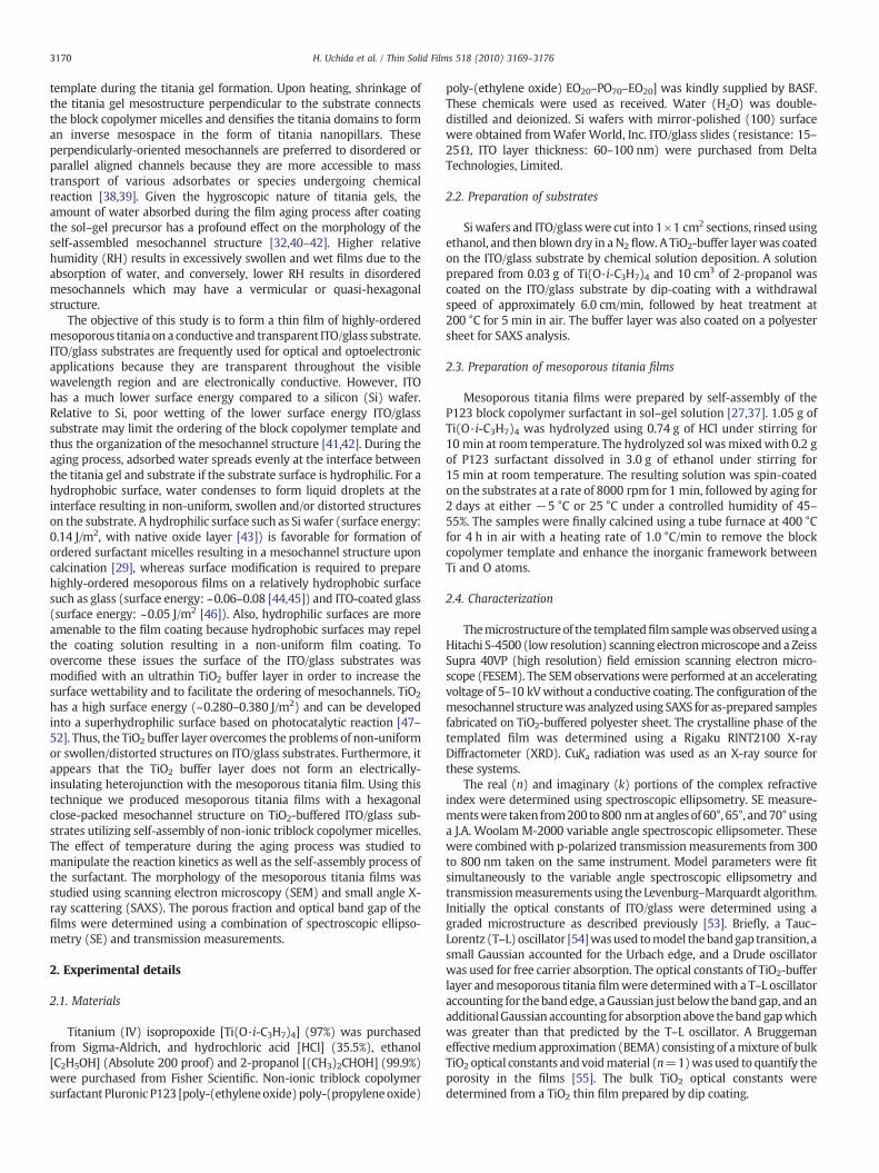
The mesoporous titania films were prepared under various agingtemperatures for the purpose of controlling the hydrolysis andcondensation reactions. As a control, the films were also formed on Siwafers and on ITO/glass substrates without a TiO2 buffer layer. Fig. 1shows low-resolution SEM images of the top surfaces for calcinedmesoporous titania films prepared directly on Si wafers at an agingtemperature of−5 °C [Fig. 1(a) and (b)] or 25 °C [Fig. 1(c) and (d)]. Forboth films, SEM images revealed highly-ordered mesochannels in ahexagonally close-packed system. As observed for similar conditions inan earlier study on a Si substrate [37], the films are composed of titaniamatrixwithdiameters on theorder of 10 nmsurroundedbypores on theorder of 10 nm [Fig. 1(b) and (d)]. The mesochannel structure wasdistributed uniformly throughout the whole surface for the film aged at−5 °C, whereas microcracks with lengths of 1–30 μm were presentacross the surface for the film aged at 25 °C. The microcracks may becaused by incomplete ordering of the inorganic matrix as a result of fasthydrolysis and condensation, resulting in rapid film densification andpore collapse which is promoted by the relatively high temperature andmoisture levels. In contrast, thewell ordered structures are formedwhenaging at−5 °C andno structural defects spanning large length scales areobserved. The large number of cracks and defects seen for the film agedat 25 °C may be attributed to both thermodynamic and kinetic factors[27]. At the lower temperature, the surfactantmicelles have time to self-assemble over longer length scales relative to the time scale forhydrolysis and condensation reactions [29,37]. The sol–gel reactionsare slowed down by the lower thermal activation aswell as the reducedamount of water in the atmosphere.
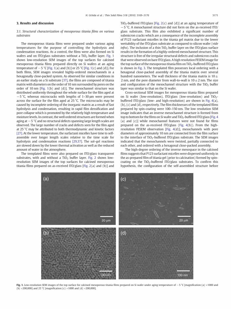
The templated films were also prepared on ITO/glass transparentsubstrates, with and without a TiO2 buffer layer. Fig. 2 shows low-resolution SEM images of the top surfaces for calcined mesoporoustitania films prepared on as-received ITO/glass [Fig. 2(a) and (b)] and
Fig. 1. Low-resolution SEM images of the top surface for calcined mesoporous titania films(b) ×200,000] and 25 °C [magnification:(c) ×1000 and (d) ×200,000].
TiO2-buffered ITO/glass [Fig. 2(c) and (d)] at an aging temperature of−5 °C. A mesochannel structure did not form on the as-received ITO/glass substrate. This film also exhibited a significant number ofsubmicron cracks which are a consequence of the incomplete assemblyof P123 surfactant micelles in the titania gel matrix due to the lowerwettability of the ITO/glass substrate as compared to silicon wafer (videinfra). The inclusion of a thin TiO2 buffer layer on the ITO/glass surfaceresults in the formationof a highly-orderedmesochannel structure. Thisstructure is free of the irregular structural defects and submicron cracksthatwere observedonbare ITO/glass. Ahigh resolutionFESEM image forthe top surfaceof themesoporous titaniafilmonTiO2-buffered ITO/glassis shown in Fig. 3. The templated film possesses local ordering with ahexagonal close-packed assembly of the titania matrix over severalhundred nanometers. The wall thickness of the titania matrix is 10±2 nm, and the pore diameter from wall-to-wall is 10±2 nm. The sizeand configuration of the mesochannel structure with the TiO2 bufferlayer was similar to that on the Si wafer.
Cross-sectional SEM images for mesoporous titania films preparedon Si wafer (low-resolution), ITO/glass (low-resolution) and TiO2-buffered ITO/glass (low- and high-resolution) are shown in Fig. 4(a),(b), (c) and (d), respectively. Thefilm thicknesses of the templatedfilmsprepared by spin-coating were 100–150 nm. The low resolution SEMimage indicates that an inverse mesochannel structure is formed fromtop to bottom for thefilmson Siwafer andTiO2-buffered ITO/glass [Fig. 4(a) and (c)] while mesochannel features were not found for filmsprepared on the as-received ITO/glass (Fig. 4(b)). From the high-resolution FESEM observation [Fig. 4(d)], mesochannels with porediameters of approximately 10 nm are connected from the film surfaceto the interface of TiO2-buffered ITO/glass substrate. The SEM imagesindicated that the mesochannels were twisted, partially connected toeach other, and ordered with a hexagonal close-packed assembly.
The high-degree ordering of the inverse mesospace in the calcinedfilms suggests that P123 surfactantmicellesweredisperseduniformly inthe as-prepared film of titania gel (prior to calcination) formed by spin-coating on the TiO2-buffered ITO/glass substrates. To confirm thishypothesis, the configuration of the self-assembled structure before
prepared on Si wafer under aging temperature of −5 °C [magnification:(a) ×1000 and
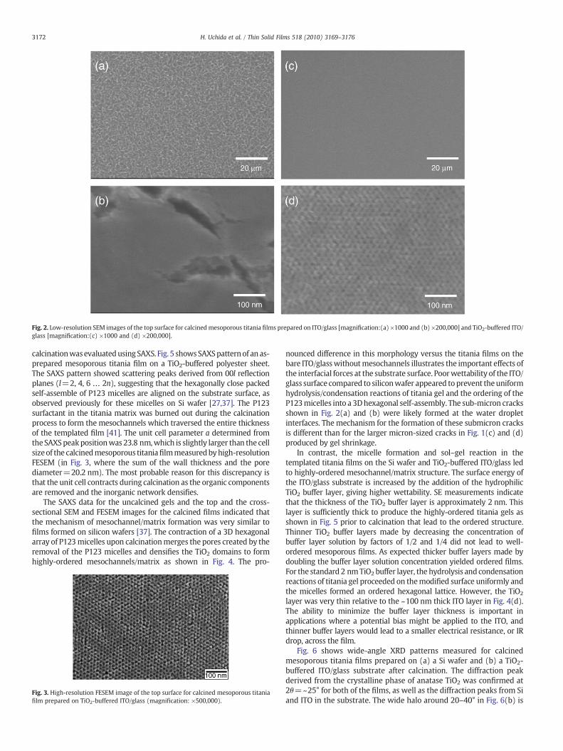
Fig. 2. Low-resolution SEM images of the top surface for calcined mesoporous titania films prepared on ITO/glass [magnification:(a) ×1000 and (b) ×200,000] and TiO2-buffered ITO/glass [magnification:(c) ×1000 and (d) ×200,000].
3172 H. Uchida et al. / Thin Solid Films 518 (2010) 3169–3176
calcinationwasevaluatedusing SAXS. Fig. 5 showsSAXSpatternof an as-prepared mesoporous titania film on a TiO2-buffered polyester sheet.The SAXS pattern showed scattering peaks derived from 00l reflectionplanes (l=2, 4, 6 … 2n), suggesting that the hexagonally close packedself-assemble of P123 micelles are aligned on the substrate surface, asobserved previously for these micelles on Si wafer [27,37]. The P123surfactant in the titania matrix was burned out during the calcinationprocess to form the mesochannels which traversed the entire thicknessof the templated film [41]. The unit cell parameter a determined fromtheSAXSpeakpositionwas 23.8 nm,which is slightly larger than the cellsizeof the calcinedmesoporous titaniafilmmeasuredbyhigh-resolutionFESEM (in Fig. 3, where the sum of the wall thickness and the porediameter=20.2 nm). The most probable reason for this discrepancy isthat the unit cell contracts during calcination as the organic componentsare removed and the inorganic network densifies.
The SAXS data for the uncalcined gels and the top and the cross-sectional SEM and FESEM images for the calcined films indicated thatthe mechanism of mesochannel/matrix formation was very similar tofilms formed on silicon wafers [37]. The contraction of a 3D hexagonalarray of P123micelles upon calcinationmerges the pores created by theremoval of the P123 micelles and densifies the TiO2 domains to formhighly-ordered mesochannels/matrix as shown in Fig. 4. The pro-
Fig. 3. High-resolution FESEM image of the top surface for calcined mesoporous titaniafilm prepared on TiO2-buffered ITO/glass (magnification: ×500,000).
nounced difference in this morphology versus the titania films on thebare ITO/glasswithoutmesochannels illustrates the important effects ofthe interfacial forces at the substrate surface. Poorwettability of the ITO/glass surface compared to siliconwafer appeared toprevent theuniformhydrolysis/condensation reactions of titania gel and the ordering of theP123micelles into a 3Dhexagonal self-assembly. The sub-micron cracksshown in Fig. 2(a) and (b) were likely formed at the water dropletinterfaces. The mechanism for the formation of these submicron cracksis different than for the larger micron-sized cracks in Fig. 1(c) and (d)produced by gel shrinkage.
In contrast, the micelle formation and sol–gel reaction in thetemplated titania films on the Si wafer and TiO2-buffered ITO/glass ledto highly-ordered mesochannel/matrix structure. The surface energy ofthe ITO/glass substrate is increased by the addition of the hydrophilicTiO2 buffer layer, giving higher wettability. SE measurements indicatethat the thickness of the TiO2 buffer layer is approximately 2 nm. Thislayer is sufficiently thick to produce the highly-ordered titania gels asshown in Fig. 5 prior to calcination that lead to the ordered structure.Thinner TiO2 buffer layers made by decreasing the concentration ofbuffer layer solution by factors of 1/2 and 1/4 did not lead to well-ordered mesoporous films. As expected thicker buffer layers made bydoubling the buffer layer solution concentration yielded ordered films.For the standard 2 nmTiO2 buffer layer, the hydrolysis and condensationreactions of titania gel proceeded on themodified surface uniformly andthe micelles formed an ordered hexagonal lattice. However, the TiO2
layer was very thin relative to the ~100 nm thick ITO layer in Fig. 4(d).The ability to minimize the buffer layer thickness is important inapplications where a potential bias might be applied to the ITO, andthinner buffer layers would lead to a smaller electrical resistance, or IRdrop, across the film.
Fig. 6 shows wide-angle XRD patterns measured for calcinedmesoporous titania films prepared on (a) a Si wafer and (b) a TiO2-buffered ITO/glass substrate after calcination. The diffraction peakderived from the crystalline phase of anatase TiO2 was confirmed at2θ=~25° for both of the films, as well as the diffraction peaks from Siand ITO in the substrate. The wide halo around 20–40° in Fig. 6(b) is
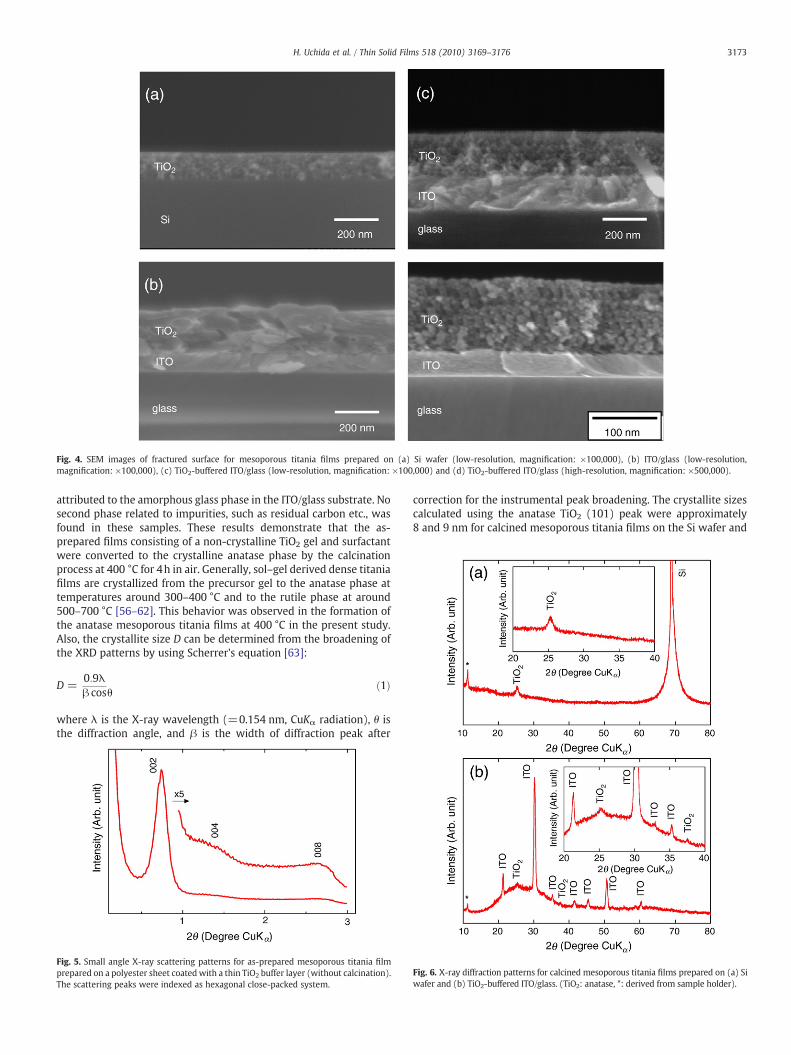
Fig. 4. SEM images of fractured surface for mesoporous titania films prepared on (a) Si wafer (low-resolution, magnification: ×100,000), (b) ITO/glass (low-resolution,magnification: ×100,000), (c) TiO2-buffered ITO/glass (low-resolution, magnification: ×100,000) and (d) TiO2-buffered ITO/glass (high-resolution, magnification: ×500,000).
3173H. Uchida et al. / Thin Solid Films 518 (2010) 3169–3176
attributed to the amorphous glass phase in the ITO/glass substrate. Nosecond phase related to impurities, such as residual carbon etc., wasfound in these samples. These results demonstrate that the as-prepared films consisting of a non-crystalline TiO2 gel and surfactantwere converted to the crystalline anatase phase by the calcinationprocess at 400 °C for 4h in air. Generally, sol–gel derived dense titaniafilms are crystallized from the precursor gel to the anatase phase attemperatures around 300–400 °C and to the rutile phase at around500–700 °C [56–62]. This behavior was observed in the formation ofthe anatase mesoporous titania films at 400 °C in the present study.Also, the crystallite size D can be determined from the broadening ofthe XRD patterns by using Scherrer's equation [63]:
D =0:9λβ cosθ
ð1Þ
where λ is the X-ray wavelength (=0.154 nm, CuKα radiation), θ isthe diffraction angle, and β is the width of diffraction peak after
Fig. 5. Small angle X-ray scattering patterns for as-prepared mesoporous titania filmprepared on a polyester sheet coated with a thin TiO2 buffer layer (without calcination).The scattering peaks were indexed as hexagonal close-packed system.
correction for the instrumental peak broadening. The crystallite sizescalculated using the anatase TiO2 (101) peak were approximately8 and 9 nm for calcined mesoporous titania films on the Si wafer and
Fig. 6. X-ray diffraction patterns for calcined mesoporous titania films prepared on (a) Siwafer and (b) TiO2-buffered ITO/glass. (TiO2: anatase, *: derived from sample holder).
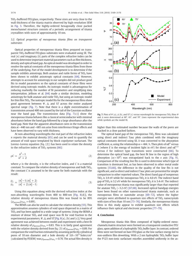
Fig. 7. Plots of Ψ (a), Δ (b), and %T (c) versus wavelength for mesoporous TiO2 films Ψand Δ were determined at 60°, 65°, and 70°. Lines represent the experimental datawhile symbols are the model fit.
3174 H. Uchida et al. / Thin Solid Films 518 (2010) 3169–3176
TiO2-buffered ITO/glass, respectively. These sizes are very close to thewall thickness of the titania matrix observed by high-resolution SEMin Fig. 3. Therefore, the highly-ordered hexagonally close packedmesochannel structure consists of a periodic arrangement of titaniacrystallites with sizes of approximately 10 nm.
3.2. Optical properties of mesoporous titania films on transparentsubstrates
Optical properties of mesoporous titania films prepared on trans-parent TiO2-buffered ITO/glass substrates were evaluated using SE. Thereal (n) and imaginary (k) parts of the complex refractive index can beused todetermine importantmaterial parameters suchasfilm thickness,density andoptical bandgap. Anopticalmodelwasdeveloped inorder toresolve the optical constants of themesoporous titania films from thoseof the underlying. Part of the model development is to determine if thesample exhibits anisotropy. Both anatase and rutile forms of TiO2 havebeen shown to exhibit anisotropic optical constants [64]. However,attempts to account for anisotropy in our samples did not produce goodfits to model parameters so the optical constants of these films werederived using isotropic models. An isotropic model is advantageous forreducing markedly the number of fit parameters and simplifying datainterpretation. Jellison et al. [64] made a similar decision, modelinganisotropy for bulk anatase and rutile TiO2 but using an isotropic modelfor thinfilmTiO2. The isotropicmodelfits for themesoporousfilms showgood agreement between Ψ, Δ, and %T across the entire analyzedspectral range (Fig. 7). Note that there is a slight overestimation oftransmission around 400 nmcaused by the tail of theGaussian oscillatornear the band gap. The transmission data [Fig. 7(c)] show themesoporous titania behaves like a classical semiconductorwithminimalabsorbance below the band gap followed by a large absorbance after theband gap. Note that the apparent absorbances seen in the transmissiondata at ~440 nm and ~685 nm arise from interference fringe effects andhave been observed to vary with thickness.
At non-absorbing wavelengths the real part of the refractive indexn reports the material density [65] and can be used to quantify theamount of void space templated by block copolymer surfactant. TheLorenz–Lorenz equation (Eq. (2)) has been used to relate the densityto the refractive index of TiO2 systems [66]:
ρC =n2−1n2 + 2
ð2Þ
where ρ is the density, n is the refractive index, and C is a materialconstant. To compare the relative density of mesoporous and bulk TiO2,the constant C is assumed to be the same for both materials with theresult:
ρ1ρ2
=ðn2
1−1Þðn22 + 2Þ
ðn21 + 2Þðn2
2−1Þ ð3Þ
Using this equation along with the derived refractive index at thenon-absorbing wavelengths from 400 to 800 nm [Fig. 8(d)], therelative density of mesoporous titania film was found to be 89%(ρporous/ρTiO2
=0.89).The BEMA can also be used to calculate the relative density [55]. This
approximation assumes cylinders of void space dispersed in a matrix ofTiO2 and has been applied to a wide range of systems. Using the BEMA amixture of dense TiO2 and void space was fit for void fraction to theexperimental parameters,Ψ,Δ, and %T [Fig. 8(a), (b) and (c)]. Very goodagreementwas achieved betweenmodel and experimentwith a best fitrelative density of ρporous/ρTiO2
=0.83. This is in fairly good agreementwith the relative density derived from Eq. (3) of ρporous/ρTiO2
=0.89. Forcomparison thevoid fraction estimatedby assumingperfectly cylindricalpores of 10 nm diameter and a hole density of 3.8×10¹¹holes/cm2
(calculated by FESEM)was ρporous/ρTiO2=0.70. The actual film density is
higher than this estimated number because the walls of the pores arestacked in a close packed fashion.
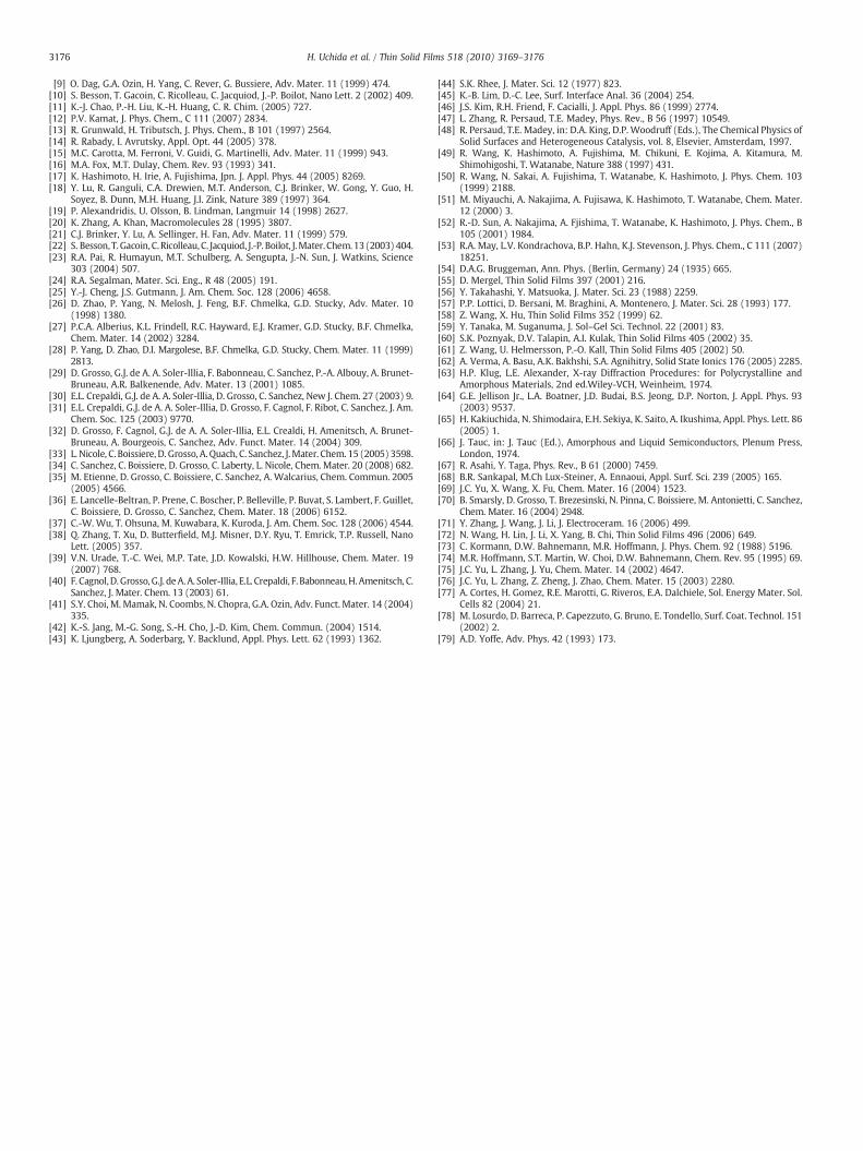
The optical band gap of the mesoporous TiO2 films was calculatedusing direct and indirect Tauc plots combined with the imaginaryoptical constants derived using SE. k was converted to the absorptioncoefficient,α, using the relationshipα=4πk/λ. Then plots ofαE2 versusE (where E is the energy of incident light in eV) for direct and αE1/2
versus E for indirect type transitions were constructed [66]. Todetermine the optical band gap, the best fit line in the region of highabsorption (α>104) was extrapolated back to the x axis (Fig. 9).Comparison of the resulting line fits is used to determine which type oftransition is dominant but, as has been observed in other metal oxidesystems [53,66], the difference in the quality of the line fits is notsignificant, and sodirect and indirect Taucplots are presented for simplecomparison to other reported values. The direct band gap of nonporousTiO2 is 3.9 eV while for mesoporous TiO2 it is 4.0 eV. The indirect bandgap of TiO2 is 3.2 eV while for mesoporous TiO2 it is 3.4 eV. The indirectvalue of mesoporous titania was significantly larger than that reportedfor anatase TiO2 (~3.2 eV) [67,68]. Increased optical bandgap energieshave been found on other nanostructured titania materials, such asmesoporous films or nanotube arrays [69–72], where the higherenergies were attributed to quantum size effects of TiO2 nanocrystalswith sizes of less than 10 nm [73–76]. Similarly, the mesoporous titaniafilms in this study appear to exhibit quantum size effects whichinfluence their optical and electronic properties [77–79].
4. Conclusion
Mesoporous titania thin films composed of highly-ordered meso-channels/matrix structure were formed on a transparent conductive ITO/glass, upon addition of a hydrophilic TiO2 buffer layer. In contrast, orderedfilms were not formed on bare ITO/glass as the low surface energy led tonon-uniform film dewetting. With a 2 nm hydrophilic TiO2 buffer layerthe P123 non-ionic surfactant micelles assembled uniformly in the as-
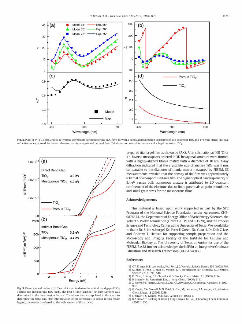
Fig. 8. Plots of Ψ (a), Δ (b), and %T (c) versus wavelength for mesoporous TiO2 films fit with a BEMA approximation consisting of 83% columnar TiO2 and 17% void space. (d) Realrefractive index, n, used for Lorentz–Lorenz density analysis and derived from T–L dispersion model for porous and sol–gel deposited TiO2.
Fig. 9. Direct (a) and indirect (b) Tauc plot used to derive the optical band gap of TiO2
(black) and mesoporous TiO2 (red). The best fit line (dashed) for both samples wasdetermined in the linear region for α>104 and was then extrapolated to the x axis todetermine the band gap. (For interpretation of the references to colour in this figurelegend, the reader is referred to the web version of this article.)
3175H. Uchida et al. / Thin Solid Films 518 (2010) 3169–3176
prepared titania gel film as shown by SAXS. After calcination at 400 °C for4h, inverse mesospaces ordered in 3D hexagonal structure were formedwith a highly-aligned titania matrix with a diameter of 10 nm. X-raydiffraction indicated that the crystallite size of anatase TiO2 was 9 nm,comparable to the diameter of titania matrix measured by FESEM. SEmeasurements revealed that the density of the film was approximately83% that of a nonporous titaniafilm. Thehigher optical bandgap energy of3.4 eV versus bulk nonporous anatase is attributed to 2D quantumconfinement of the electrons due to finite potentials at grain boundariesand small grain sizes for the mesoporous films.
Acknowledgements
This material is based upon work supported in part by the STCProgram of the National Science Foundation under Agreement CHE-9876674, the Department of Energy Office of Basic Energy Sciences, theRobert A.Welch Foundation (Grant F-1319and F-1529), and theProcessScience andTechnologyCenter at theUniversity of Texas.Wewould liketo thankDr. BrianA. Korgel, Dr. Peter F. Green,Dr. Yuan Li, Dr. DohC. Lee,and Andrew T. Heitsch for supporting sample preparation and theMicroscopy and Imaging Facility of the Institute for Cellular andMolecular Biology at The University of Texas at Austin for use of theFESEM.R.A.M. further acknowledges theNSF for an IntegrativeGraduateEducation and Research Traineeship (DGE-054917).
References
[1] C.T. Kresge, M.E. Leonowicz, W.J. Roth, J.C. Vartuli, J.S. Beck, Nature 359 (1992) 710.[2] D. Zhao, J. Feng, Q. Huo, N. Melosh, G.H. Fredrickson, B.F. Chmelka, G.D. Stucky,
Science 279 (1998) 548.[3] D. Zhao, P. Yang, B.F. Chmelka, G.D. Stucky, Chem. Mater. 11 (1999) 1174.[4] B. Smarsly, M. Antonietti, Eur. J. Inorg. Chem. (2006) 1111.[5] Z. Konya, V.F. Puntes, I. Kiricsi, J. Zhu, A.P. Alivisatos, G.A. Somorjai, Nano Lett. 2 (2002)
907.[6] G. Gupta, C.A. Stowell, M.N. Patel, X. Gao, M.J. Yacaman, B.A. Korgel, K.P. Johnston,
Chem. Mater. 18 (2006) 6239.[7] S. Sircar, T.C. Golden, M.B. Rao, Carbon 34 (1996) 1.[8] K.A. Kilian, T. Bocking, K. Gaus, J. King-Lacroix, M. Gal, J.J. Gooding, Chem. Commun.
(2007) 1936.
3176 H. Uchida et al. / Thin Solid Films 518 (2010) 3169–3176
[9] O. Dag, G.A. Ozin, H. Yang, C. Rever, G. Bussiere, Adv. Mater. 11 (1999) 474.[10] S. Besson, T. Gacoin, C. Ricolleau, C. Jacquiod, J.-P. Boilot, Nano Lett. 2 (2002) 409.[11] K.-J. Chao, P.-H. Liu, K.-H. Huang, C. R. Chim. (2005) 727.[12] P.V. Kamat, J. Phys. Chem., C 111 (2007) 2834.[13] R. Grunwald, H. Tributsch, J. Phys. Chem., B 101 (1997) 2564.[14] R. Rabady, I. Avrutsky, Appl. Opt. 44 (2005) 378.[15] M.C. Carotta, M. Ferroni, V. Guidi, G. Martinelli, Adv. Mater. 11 (1999) 943.[16] M.A. Fox, M.T. Dulay, Chem. Rev. 93 (1993) 341.[17] K. Hashimoto, H. Irie, A. Fujishima, Jpn. J. Appl. Phys. 44 (2005) 8269.[18] Y. Lu, R. Ganguli, C.A. Drewien, M.T. Anderson, C.J. Brinker, W. Gong, Y. Guo, H.
Soyez, B. Dunn, M.H. Huang, J.I. Zink, Nature 389 (1997) 364.[19] P. Alexandridis, U. Olsson, B. Lindman, Langmuir 14 (1998) 2627.[20] K. Zhang, A. Khan, Macromolecules 28 (1995) 3807.[21] C.J. Brinker, Y. Lu, A. Sellinger, H. Fan, Adv. Mater. 11 (1999) 579.[22] S. Besson, T. Gacoin, C. Ricolleau, C. Jacquiod, J.-P. Boilot, J.Mater.Chem.13(2003)404.[23] R.A. Pai, R. Humayun, M.T. Schulberg, A. Sengupta, J.-N. Sun, J. Watkins, Science
303 (2004) 507.[24] R.A. Segalman, Mater. Sci. Eng., R 48 (2005) 191.[25] Y.-J. Cheng, J.S. Gutmann, J. Am. Chem. Soc. 128 (2006) 4658.[26] D. Zhao, P. Yang, N. Melosh, J. Feng, B.F. Chmelka, G.D. Stucky, Adv. Mater. 10
(1998) 1380.[27] P.C.A. Alberius, K.L. Frindell, R.C. Hayward, E.J. Kramer, G.D. Stucky, B.F. Chmelka,
Chem. Mater. 14 (2002) 3284.[28] P. Yang, D. Zhao, D.I. Margolese, B.F. Chmelka, G.D. Stucky, Chem. Mater. 11 (1999)
2813.[29] D. Grosso, G.J. de A. A. Soler-Illia, F. Babonneau, C. Sanchez, P.-A. Albouy, A. Brunet-
Bruneau, A.R. Balkenende, Adv. Mater. 13 (2001) 1085.[30] E.L. Crepaldi, G.J. de A. A. Soler-Illia, D. Grosso, C. Sanchez, New J. Chem. 27 (2003) 9.[31] E.L. Crepaldi, G.J. de A. A. Soler-Illia, D. Grosso, F. Cagnol, F. Ribot, C. Sanchez, J. Am.
Chem. Soc. 125 (2003) 9770.[32] D. Grosso, F. Cagnol, G.J. de A. A. Soler-Illia, E.L. Crealdi, H. Amenitsch, A. Brunet-
Bruneau, A. Bourgeois, C. Sanchez, Adv. Funct. Mater. 14 (2004) 309.[33] L. Nicole, C. Boissiere, D. Grosso, A. Quach, C. Sanchez, J.Mater. Chem. 15 (2005) 3598.[34] C. Sanchez, C. Boissiere, D. Grosso, C. Laberty, L. Nicole, Chem. Mater. 20 (2008) 682.[35] M. Etienne, D. Grosso, C. Boissiere, C. Sanchez, A. Walcarius, Chem. Commun. 2005
(2005) 4566.[36] E. Lancelle-Beltran, P. Prene, C. Boscher, P. Belleville, P. Buvat, S. Lambert, F. Guillet,
C. Boissiere, D. Grosso, C. Sanchez, Chem. Mater. 18 (2006) 6152.[37] C.-W. Wu, T. Ohsuna, M. Kuwabara, K. Kuroda, J. Am. Chem. Soc. 128 (2006) 4544.[38] Q. Zhang, T. Xu, D. Butterfield, M.J. Misner, D.Y. Ryu, T. Emrick, T.P. Russell, Nano
Lett. (2005) 357.[39] V.N. Urade, T.-C. Wei, M.P. Tate, J.D. Kowalski, H.W. Hillhouse, Chem. Mater. 19
(2007) 768.[40] F. Cagnol,D. Grosso, G.J. deA.A. Soler-Illia, E.L. Crepaldi, F. Babonneau,H. Amenitsch, C.
Sanchez, J. Mater. Chem. 13 (2003) 61.[41] S.Y. Choi, M. Mamak, N. Coombs, N. Chopra, G.A. Ozin, Adv. Funct. Mater. 14 (2004)
335.[42] K.-S. Jang, M.-G. Song, S.-H. Cho, J.-D. Kim, Chem. Commun. (2004) 1514.[43] K. Ljungberg, A. Soderbarg, Y. Backlund, Appl. Phys. Lett. 62 (1993) 1362.
[44] S.K. Rhee, J. Mater. Sci. 12 (1977) 823.[45] K.-B. Lim, D.-C. Lee, Surf. Interface Anal. 36 (2004) 254.[46] J.S. Kim, R.H. Friend, F. Cacialli, J. Appl. Phys. 86 (1999) 2774.[47] L. Zhang, R. Persaud, T.E. Madey, Phys. Rev., B 56 (1997) 10549.[48] R. Persaud, T.E. Madey, in: D.A. King, D.P. Woodruff (Eds.), The Chemical Physics of
Solid Surfaces and Heterogeneous Catalysis, vol. 8, Elsevier, Amsterdam, 1997.[49] R. Wang, K. Hashimoto, A. Fujishima, M. Chikuni, E. Kojima, A. Kitamura, M.
Shimohigoshi, T. Watanabe, Nature 388 (1997) 431.[50] R. Wang, N. Sakai, A. Fujishima, T. Watanabe, K. Hashimoto, J. Phys. Chem. 103
(1999) 2188.[51] M. Miyauchi, A. Nakajima, A. Fujisawa, K. Hashimoto, T. Watanabe, Chem. Mater.
12 (2000) 3.[52] R.-D. Sun, A. Nakajima, A. Fjishima, T. Watanabe, K. Hashimoto, J. Phys. Chem., B
105 (2001) 1984.[53] R.A. May, L.V. Kondrachova, B.P. Hahn, K.J. Stevenson, J. Phys. Chem., C 111 (2007)
18251.[54] D.A.G. Bruggeman, Ann. Phys. (Berlin, Germany) 24 (1935) 665.[55] D. Mergel, Thin Solid Films 397 (2001) 216.[56] Y. Takahashi, Y. Matsuoka, J. Mater. Sci. 23 (1988) 2259.[57] P.P. Lottici, D. Bersani, M. Braghini, A. Montenero, J. Mater. Sci. 28 (1993) 177.[58] Z. Wang, X. Hu, Thin Solid Films 352 (1999) 62.[59] Y. Tanaka, M. Suganuma, J. Sol–Gel Sci. Technol. 22 (2001) 83.[60] S.K. Poznyak, D.V. Talapin, A.I. Kulak, Thin Solid Films 405 (2002) 35.[61] Z. Wang, U. Helmersson, P.-O. Kall, Thin Solid Films 405 (2002) 50.[62] A. Verma, A. Basu, A.K. Bakhshi, S.A. Agnihitry, Solid State Ionics 176 (2005) 2285.[63] H.P. Klug, L.E. Alexander, X-ray Diffraction Procedures: for Polycrystalline and
Amorphous Materials, 2nd ed.Wiley-VCH, Weinheim, 1974.[64] G.E. Jellison Jr., L.A. Boatner, J.D. Budai, B.S. Jeong, D.P. Norton, J. Appl. Phys. 93
(2003) 9537.[65] H. Kakiuchida, N. Shimodaira, E.H. Sekiya, K. Saito, A. Ikushima, Appl. Phys. Lett. 86
(2005) 1.[66] J. Tauc, in: J. Tauc (Ed.), Amorphous and Liquid Semiconductors, Plenum Press,
London, 1974.[67] R. Asahi, Y. Taga, Phys. Rev., B 61 (2000) 7459.[68] B.R. Sankapal, M.Ch Lux-Steiner, A. Ennaoui, Appl. Surf. Sci. 239 (2005) 165.[69] J.C. Yu, X. Wang, X. Fu, Chem. Mater. 16 (2004) 1523.[70] B. Smarsly, D. Grosso, T. Brezesinski, N. Pinna, C. Boissiere, M. Antonietti, C. Sanchez,
Chem. Mater. 16 (2004) 2948.[71] Y. Zhang, J. Wang, J. Li, J. Electroceram. 16 (2006) 499.[72] N. Wang, H. Lin, J. Li, X. Yang, B. Chi, Thin Solid Films 496 (2006) 649.[73] C. Kormann, D.W. Bahnemann, M.R. Hoffmann, J. Phys. Chem. 92 (1988) 5196.[74] M.R. Hoffmann, S.T. Martin, W. Choi, D.W. Bahnemann, Chem. Rev. 95 (1995) 69.[75] J.C. Yu, L. Zhang, J. Yu, Chem. Mater. 14 (2002) 4647.[76] J.C. Yu, L. Zhang, Z. Zheng, J. Zhao, Chem. Mater. 15 (2003) 2280.[77] A. Cortes, H. Gomez, R.E. Marotti, G. Riveros, E.A. Dalchiele, Sol. Energy Mater. Sol.
Cells 82 (2004) 21.[78] M. Losurdo, D. Barreca, P. Capezzuto, G. Bruno, E. Tondello, Surf. Coat. Technol. 151
(2002) 2.[79] A.D. Yoffe, Adv. Phys. 42 (1993) 173.


![Last Update: 23 July, 2013 Papers Published in ISI ......Last Update: 23 July, 2013 3 [198] Synthesis of Fine Gold Nanoparticles in Mesoporous Titania Nanoparticles through Different](https://img.pdfslide.net/doc/110x75/5e3053007cfa7617b0486355/last-update-23-july-2013-papers-published-in-isi-last-update-23-july.jpg)