Embed Size (px)
Citation preview

Highly-reliable Design Technology of Steam Turbine for Nuclear Power Plant 102
Highly-reliable Design Technology of Steam Turbine for Nuclear Power Plant
Tateki NakamuraKiyoshi SegawaNobuhiro Isobe, Dr. Eng.Takashi Saito
INTRODUCTIONSTEAM turbines are one of the key energy conversion device used at nuclear power plants, and the requirements for larger, more reliable, and more
efficient turbines, which were already increasing, are growing even stronger. Hitachi has designed and developed steam turbines with low-pressure LSBs (last-stage blades) up to 52 inches (1.32 m)
Utilities electrical room
Oil tank Cooling water pump
Steam turbine test facility
Inverter motor-generator
Model turbineGear boxCooling towerInverter electrical room
for motor-generator
Flashback simulation tank
Test boiler Central turbine control room Condenser
Fig. 1—Steam Turbine Test Facility.The facility uses a model turbine that simulates an actual turbine to calculate and confirm the steam flow distribution in the turbine and the turbine behavior when operating under steam load.
OVERVIEW: Steam turbines are a critical part of the power plants and demands for larger size, higher reliability, and higher efficiency will only strengthen in the current environment where it is clear that the role of large-scale nuclear power plants will grow as means to reduce CO2 and counter global warming. In particular, the long blades in the low-pressure stage are the most important components in the steam turbine in terms of turbine efficiency and output, and Hitachi has been working on the design and development of these blades to meet the demand for high reliability and high efficiency by designing blades based on the latest finding. In 2006, in response to damage to stage 12 (L-2) blades in a low-pressure turbine in an ABWR, Hitachi used the latest analysis techniques to design a new blade and test its structural reliability. Testing of the model turbine was carried out under steam load and operating tests were performed on the full-scale model that had been constructed and/or augmented at the recently installed test facility.

Hitachi Review Vol. 58 (2009), No.2 103
for use in 60 Hz/1,800 rpm (revolutions per minute) and 50-Hz/1,500-rpm units for the nuclear power industry, and is installing these in actual plants (see Fig. 2)(1). This design and development combines analysis techniques that have become faster and more precise in recent years with verification via experimental trials.
This ar t ic le descr ibes the latest analysis techniques(2) and also testing of a model turbine carried out under steam load and operating tests on a full-scale model undertaken as part of the design and structural reliability testing of the new blade intended to provide a long term solution to the problem of damage discovered in the stage 12 (L-2) blades in low-pressure turbines used with ABWRs (advanced boiling water reactors) at Chubu Electric Power Co., Inc.’s Hamaoka Nuclear Power Station Unit 5 and Unit 2 of Hokuriku Electric Power Company’s Shika Nuclear Power Station.
APPLICATION OF THE LATEST FLUID ANALYSIS TECHNIQUES AND DEVELOPMENT OF NEW BLADEUse of the Latest Fluid Analysis Techniques to Identify Cause of Damage
A multi-stage quasi-three-dimensional unsteady flow analysis of a 60-Hz/1,800-rpm steam turbine with 52-inch low-pressure LSBs run on a state-of-the-art supercomputer produced two new findings: (1) at low load, the influence of the region of turbulence in the main flow, which in the past had been assumed to only reach as far as the L-0 or L-1 stage, actually extends as far as the L-2 stage and causes random vibration in the L-2 blades, and (2) when the load is interrupted, reverse flow (flashback) of steam from
the feed-water heater causes blade vibration which is superimposed on top of the random vibration. This confirmed that the damage in the previous L-2 blade was caused by the action of vibrational stresses in excess of the fatigue limit (see Fig. 3).
Multi-stage quasi-three-dimensional unsteady flow analysis can analyze the steam flow between stages in a comparatively short time and this allows the design of the flow pattern in the turbine to be performed more quickly and with greater accuracy.
Basic Strategy and Structure for Developing New Blade
In deciding how to counter this problem, the phenomena of a region of turbulent flow occurring in the main flow at low load and flashback occurring when the load is interrupted were recognized as unavoidable in usual operation. Accordingly, the approach taken in the design and development of the new blade that will provide the long-term solution to the problem was to reduce the vibrational stress
Vibrational stresses build up due to random vibration
and flashback.
The region of turbulence in the main flow when operating
under load extends to the L-2 stage (stage 12).
Flashback (reverse flow of the steam) occurs in the L-2 stage (stage 12) from the No. 5 extraction when
the load is interrupted.
Larger turbines
Crack initiation and growth occur due to high cycle fatigue.
Flashback steam
Random vibration caused by region of turbulent flow
: Recent findings (identified here through use of the latest simulation techniques) The phenomenon of the region of turbulent flow extending to the L-2 stage of a steam turbine is a new finding that has not been reported in the existing literature.
L-3 stage(Stage 11)
L-2 stage(Stage 12)
L-1 stage(Stage 13)
L-0 stage(Stage 14)
Fig. 2—60-Hz/1,800-rpm Steam Turbine with 52-inch Low-pressure LSBs (Last-stage Blades).The outline of the 60-Hz/1,800-rpm steam turbine with 52-inch low-pressure LSBs is shown.
Fig. 3—Damage Mechanism and Results of Turbine Internal Flow Simulation.The results of multi-stage quasi-three-dimensional unsteady flow analysis conducted on a state-of-the-art supercomputer are shown.
Highly-reliable Design Technology of Steam Turbine for Nuclear Power Plant 104
in the turbine and the vibrational stresses due to the forces induced by the steam acting on the blade.
Full-scale Operating Model Test FacilityFig. 5 shows a photograph of the full-scale
operating model test facility. This test facility is used to verify the basic characteristics of the blade using a full-scale test rotor fitted with prototype blades with the same specifications as the actual blade. It allows measurements and verification to be performed with the unit subject to vibrational stresses applied by a vibrator unit equivalent to those under actual operating loads.
In addition to the strain gauge telemetry used in previous systems, the measurement instruments included a non-contact sensor able to measure the vibrational characteristics of all blades.
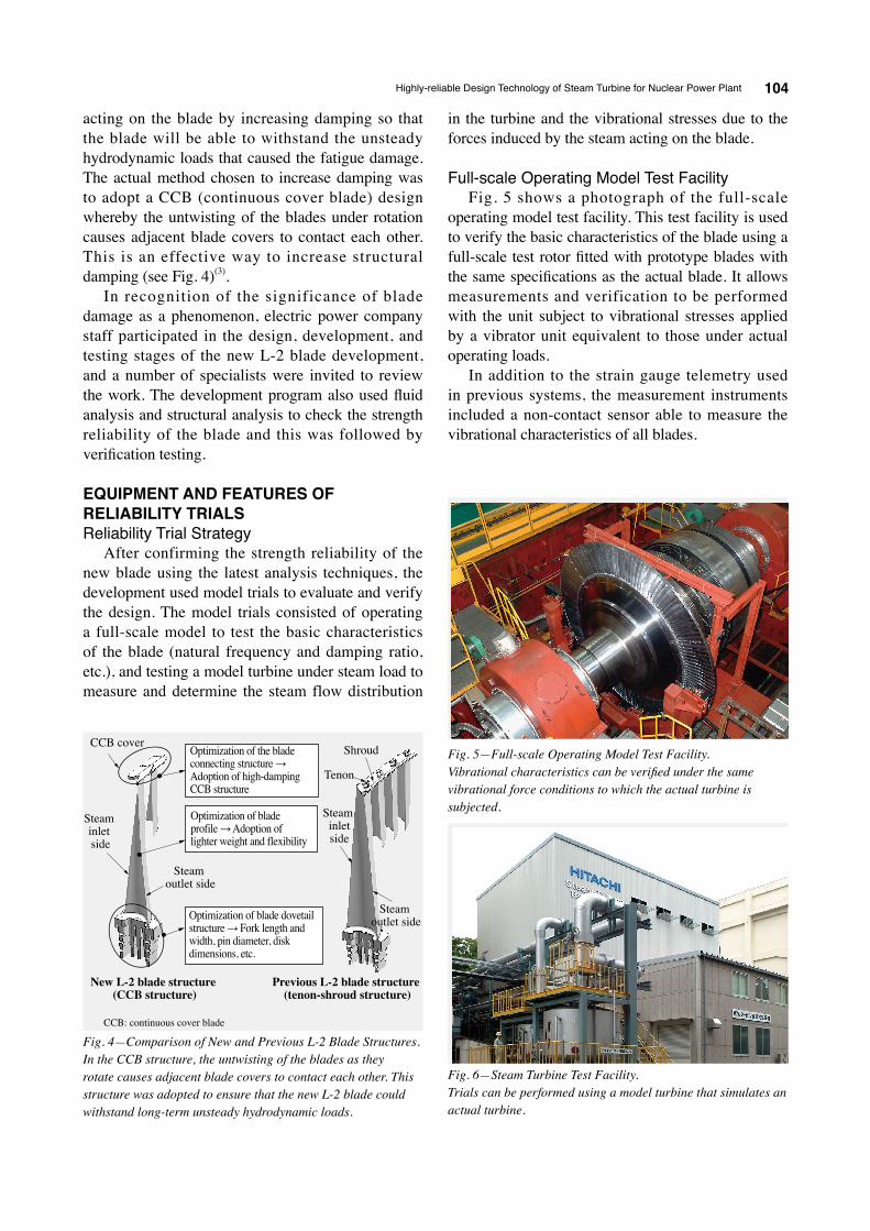
acting on the blade by increasing damping so that the blade will be able to withstand the unsteady hydrodynamic loads that caused the fatigue damage. The actual method chosen to increase damping was to adopt a CCB (continuous cover blade) design whereby the untwisting of the blades under rotation causes adjacent blade covers to contact each other. This is an effective way to increase structural damping (see Fig. 4)(3).
In recognition of the significance of blade damage as a phenomenon, electric power company staff participated in the design, development, and testing stages of the new L-2 blade development, and a number of specialists were invited to review the work. The development program also used fluid analysis and structural analysis to check the strength reliability of the blade and this was followed by verification testing.
EQUIPMENT AND FEATURES OF RELIABILITY TRIALSReliability Trial Strategy
After confirming the strength reliability of the new blade using the latest analysis techniques, the development used model trials to evaluate and verify the design. The model trials consisted of operating a full-scale model to test the basic characteristics of the blade (natural frequency and damping ratio, etc.), and testing a model turbine under steam load to measure and determine the steam flow distribution
Fig. 5—Full-scale Operating Model Test Facility.Vibrational characteristics can be verified under the same vibrational force conditions to which the actual turbine is subjected.
Fig. 6—Steam Turbine Test Facility.Trials can be performed using a model turbine that simulates an actual turbine.
Steam outlet side
Steam outlet side
Steam inletside
Steam inlet side
CCB coverOptimization of the blade connecting structure → Adoption of high-damping CCB structure
Optimization of blade profile → Adoption of lighter weight and flexibility
Optimization of blade dovetail structure → Fork length and width, pin diameter, disk dimensions, etc.
New L-2 blade structure (CCB structure)
Previous L-2 blade structure (tenon-shroud structure)
Tenon
Shroud
Fig. 4—Comparison of New and Previous L-2 Blade Structures.In the CCB structure, the untwisting of the blades as they rotate causes adjacent blade covers to contact each other. This structure was adopted to ensure that the new L-2 blade could withstand long-term unsteady hydrodynamic loads.
CCB: continuous cover blade

Hitachi Review Vol. 58 (2009), No.2 105
Steam Turbine Test FacilityFig. 6 shows a photograph of the steam turbine
test facility used to test the model turbine under steam load. The model turbine simulates an actual turbine and can be used to measure the vibrational stresses to which the blades are subjected when operating under steam load. The model turbine is also fitted with the latest sensors from airplane engine and rocket development that can measure the steam flow distribution in the turbine directly.
The model turbine has the same casing and extraction configuration as an actual turbine and other features include a tank for simulating flashback and an inverter motor-generator that can maintain rotational speed when operating at low load and instantly switch from generator mode to motor mode when the load is interrupted.
The test facility is operated from the central control room shown in Fig. 7. By providing integrated supervision and control of operation and measurement, this allows high-precision tests and measurements to be performed efficiently (see Fig. 8).
Test ResultsThe natural frequency is one of the basic
characteristics of a turbine blade. The full-scale operating model test measured the natural frequency of the new L-2 blade and confirmed that there is adequate separation from the resonance point at the rated operating speed (see Fig. 9). It was also
confirmed that, due to the adoption of the CCB structure, the damping ratio calculated from the resonant response curve was several times that of the previous L-2 blade.
The results of testing the model turbine under steam load confirmed that the region of reverse flow under low load extended as far as the L-2 stage, as predicted by the quasi-three-dimensional unsteady flow analysis conducted on a state-of-the-art supercomputer, verifying the accuracy of the analysis. The tests also confirmed that, due to the increase in the damping ratio, the vibrational stresses on the new L-2 blade are significantly less than those that caused damage to the previous L-2 blade and that there is an adequate margin below the fatigue limit (see Fig. 10).
Future OutlookHitachi is proceeding with various trials using
the model turbine to simulate actual turbines at the trial facility and the results of evaluating and analyzing the data produced by these trials are being put to use in the design and development of turbine blades to meet the demand for turbines with higher performance and better reliability.
Total pressure hole
Total pressure/temperature tube
Thermocouples
Fig. 7—Central Control Room for the Steam Turbine Test Facility and Example Screen.The central control room provides integrated supervision and control of the turbine operation and measurements.
Fig. 8—Measurement Instruments Used at Steam Turbine Test Facility.The instruments can automatically measure the steam flow distribution in the model turbine.

Highly-reliable Design Technology of Steam Turbine for Nuclear Power Plant 106
intends to continue its research and development into turbine technologies with even better reliability and higher efficiency.
REFERENCES(1) N. Kajiyama et al., “Construction of Hamaoka Nuclear
Power Station Unit 5 of Chubu Electric Power Co., Inc.,” Hitachi Hyoron 87, pp. 193 - 198 (Feb. 2005) in Japanese.
(2) A. Okuno et al., “Analysis of Blade Stage in Turbine with Integrated Seal,” Proceedings of the JSME Computational Mechanics Conference, No. 640 (Nov. 2008) in Japanese.
(3) T. Kudo et al., “48-Inch Steel Last-Stage Blade with the World’s Largest Annulus Area,” Hitachi Hyoron 88, pp. 197 - 200 (Feb. 2006) in Japanese.
CONCLUSIONSThis article has summarized the latest analysis
techniques and test facilities used in the development of a new L-2 blade for the low-pressure turbines used in ABWRs, and the results that have been obtained.
By utilizing these latest analysis techniques and test facilities, Hitachi can develop technologies that provide both the high efficiency and high reliability required to meet customer needs and help reduce the burden on the environment.
In designing and developing the next generation of thermal and nuclear power turbines, a field which has been becoming increasingly important in recent years as an effective way of reducing CO2, Hitachi
New L-2 bladePrevious L-2 blade
Stress evaluation
App
lied
stre
ss/fa
tigue
lim
it
4
1
0Rotation (rps)
Freq
uenc
y (H
z)
0 10 20 30
1
2
3
4
5
6
7
8
910
400
3rd-mode
2nd-mode
1st-mode
300
200
100
0
1112
Rotation (rps)
Freq
uenc
y (H
z)
0 10 20 30
1
2
3
4
5
6
7
8
910
400
1st-mode
300
200
100
0
1112
Fig. 10—Blade Vibrational Stress when Load Interrupted.The improvement in the fatigue limit for the blade groove due to the lighter design of the new L-2 blade and the reduction in vibrational stresses due to the increased attenuation ensure a sufficient margin below the fatigue limit.
Fig. 9—Campbell Diagrams for Previous (left) and New (right) L-2 Blades.An adequate separation from the resonance point at the operating speed is shown.
ABOUT THE AUTHORS
Tateki NakamuraJoined Hitachi, Ltd. in 2004, and now works at the Turbine Plant Design Department, Hitachi Works, Power Systems. He is currently engaged in the design and development of steam turbines.
rps: revolutions per second
Kiyoshi SegawaJoined Hitachi, Ltd. in 1990, and now works at the Energy and Environmental Systems Laboratory, Power Systems. He is currently engaged in the research and development of steam turbines. Mr. Segawa is a member of The Japan Society of Mechanical Engineers (JSME) and the Turbomachinery Society of Japan.
Nobuhiro Isobe, Dr. Eng.Joined Hitachi, Ltd. in 1993, and now works at the Hitachi Research Laboratory, Research & Development Group. He is currently engaged in the research and development of structure strength reliability. Dr. Isobe is a member of JSME, The Society of Materials Science, Japan, and the Gas Turbine Society of Japan.
Takashi SaitoJoined Hitachi, Ltd. in 1982, and now works at the Nuclear Power Service Business Department, Hitachi-GE Nuclear Energy, Ltd. He is currently engaged in the preventive maintenance service of nuclear power plants.