Embed Size (px)
DESCRIPTION
civil eng
Citation preview
Highway Engineering-I
Chapter One:
INTODUCTION TO TRANSPORT SYSTEM AND PLANNING
ASTU/Civil Engineering Dept.
Instructor: Fasika Mekonnen
1
1. INTRODUCTION
2
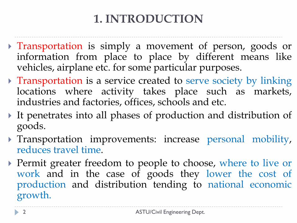
Transportation is simply a movement of person, goods or information from place to place by different means like vehicles, airplane etc. for some particular purposes.
Transportation is a service created to serve society by linking locations where activity takes place such as markets, industries and factories, offices, schools and etc.
It penetrates into all phases of production and distribution of goods.
Transportation improvements: increase personal mobility, reduces travel time.
Permit greater freedom to people to choose, where to live or work and in the case of goods they lower the cost of production and distribution tending to national economic growth.
ASTU/Civil Engineering Dept.
2. TRANSPORT SYSTEM
3
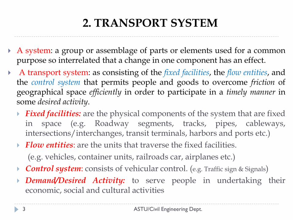
A system: a group or assemblage of parts or elements used for a common purpose so interrelated that a change in one component has an effect.
A transport system: as consisting of the fixed facilities, the flow entities, and the control system that permits people and goods to overcome friction of geographical space efficiently in order to participate in a timely manner in some desired activity.
Fixed facilities: are the physical components of the system that are fixed in space (e.g. Roadway segments, tracks, pipes, cableways, intersections/interchanges, transit terminals, harbors and ports etc.)
Flow entities: are the units that traverse the fixed facilities.
(e.g. vehicles, container units, railroads car, airplanes etc.)
Control system: consists of vehicular control. (e.g. Traffic sign & Signals)
Demand/Desired Activity: to serve people in undertaking their economic, social and cultural activities
ASTU/Civil Engineering Dept.
Objective of Transportation system
4
helps in the movement of passengers and freight from one location to another.
relates the population to the land use.
acts as an integrating and coordinating factor in the highly complex and industrialized society.
provides the place utility and time utility to product.
ASTU/Civil Engineering Dept.
Merits/Advantages of Transportation System
5
Economic Front: It relates population to land use by moving them from one place to
another. It increases the production by creating demand, easily availability
and reducing prices. It has vast potential of generating employment. New markets get developed near production centers.
Political Front: Different regions of the country are made interdependent. Transportation has developed a sense of national unity. Fulfills the defense and strategic needs of a country.
Social Front: Life becomes more enjoyable and comfortable. It provides emergency services available at your door. It has helped in raising the standards of living of people. The settlement pattern in the country is controlled by it.
ASTU/Civil Engineering Dept.
Demerits/Disadvantages of Transportation System:
6
With the development of large scale industries the cottage industries have been eliminated.
The area loses its distinguishing characteristics.
The environmentalist pollutions related to air, water, noise, aesthetics, vibrations get increased and create health problems.
The expansion of transportation system sometimes affects the recreational activities provided in the area.
It has changed the traditions and customs of families along with modes of living.
ASTU/Civil Engineering Dept.
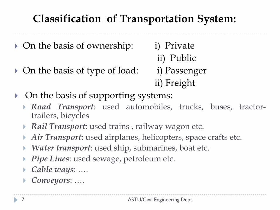
Classification of Transportation System:
7
On the basis of ownership: i) Private
ii) Public
On the basis of type of load: i) Passenger
ii) Freight
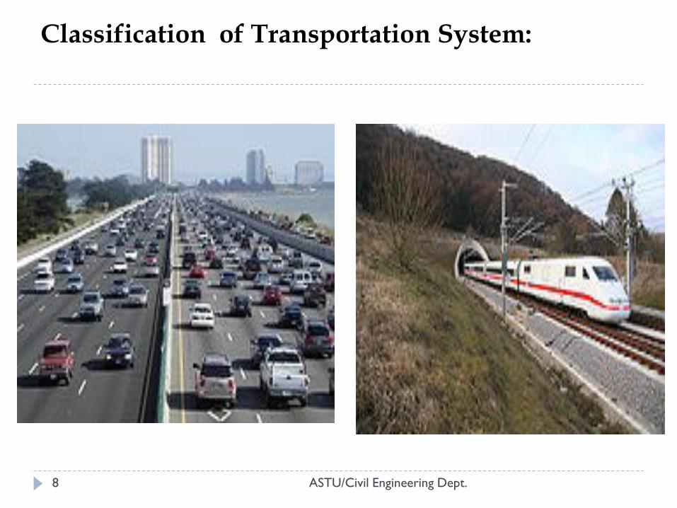
On the basis of supporting systems: Road Transport: used automobiles, trucks, buses, tractor-
trailers, bicycles
Rail Transport: used trains , railway wagon etc.
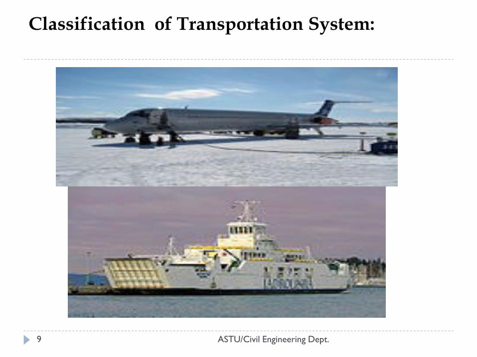
Air Transport: used airplanes, helicopters, space crafts etc.
Water transport: used ship, submarines, boat etc.
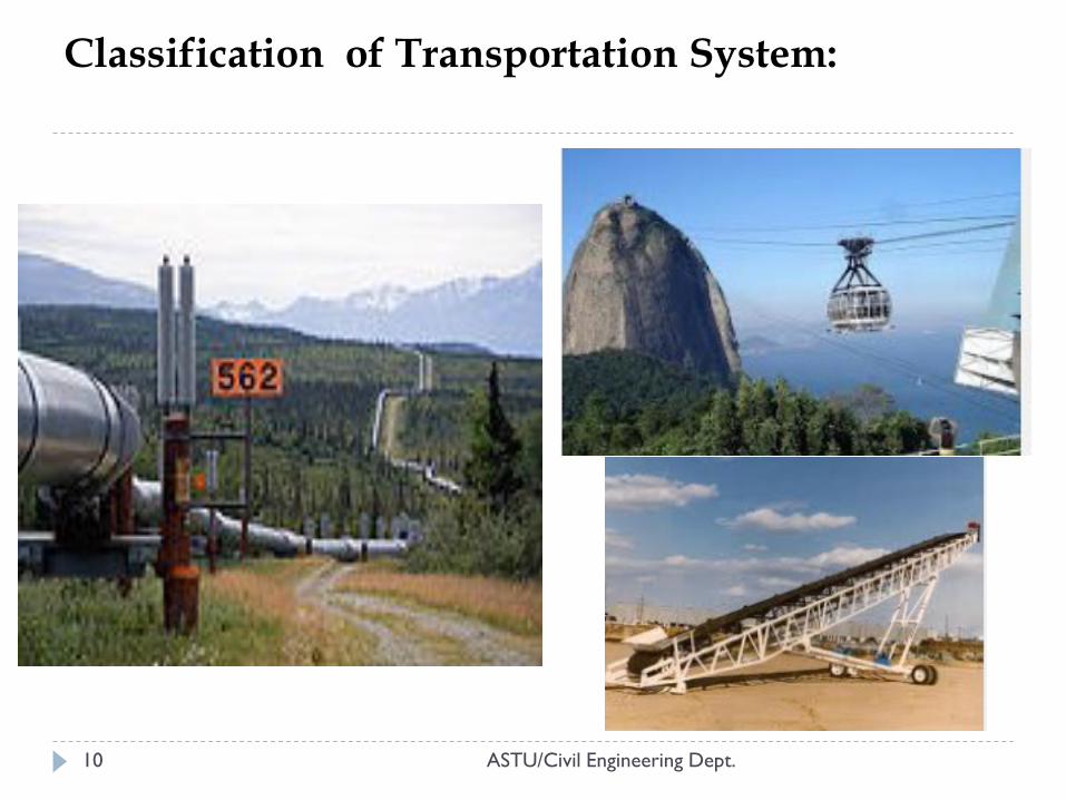
Pipe Lines: used sewage, petroleum etc.
Cable ways: ….
Conveyors: ….
ASTU/Civil Engineering Dept.
ASTU/Civil Engineering Dept. 8
Classification of Transportation System:
ASTU/Civil Engineering Dept. 9
Classification of Transportation System:
ASTU/Civil Engineering Dept. 10
Classification of Transportation System:
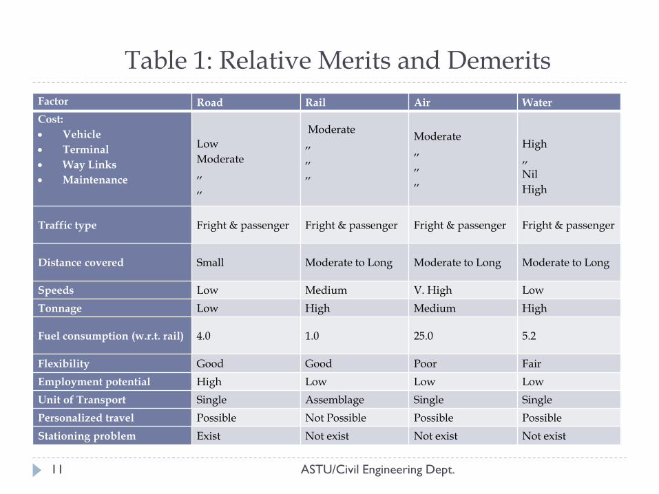
Table 1: Relative Merits and Demerits
11
Factor Road Rail Air Water
Cost:
Vehicle
Terminal
Way Links
Maintenance
Low
Moderate
,,
,,
Moderate
,,
,,
,,
Moderate
,,
,,
,,
High
,,
Nil
High
Traffic type Fright & passenger Fright & passenger Fright & passenger Fright & passenger
Distance covered Small Moderate to Long Moderate to Long Moderate to Long
Speeds Low Medium V. High Low
Tonnage Low High Medium High
Fuel consumption (w.r.t. rail) 4.0 1.0 25.0 5.2
Flexibility Good Good Poor Fair
Employment potential High Low Low Low
Unit of Transport Single Assemblage Single Single
Personalized travel Possible Not Possible Possible Possible
Stationing problem Exist Not exist Not exist Not exist
ASTU/Civil Engineering Dept.
Suitability of Transportation Systems
12
The systems and modes of transport are generally evaluated in terms of the basic attributes:
Accessibility and utility: distance and flexibility.
Mobility: handling capacity and speed.
Efficiency: direct and indirect cost of transportation.
ASTU/Civil Engineering Dept.
Specialties in Transportation Engineering
13
Planning
deals with selection of projects, defining the problem, gathering and analyzing data, and evaluating various alternative solutions.
forecast of future traffic; estimate of impact of the facility on land use, the environment, the community; and determination of the benefits and cost that will result if the project is built.
Design
involves the specification of all features of the transportation system so that will function smoothly, efficiently, and in accord with physical laws.
used for estimating the facility costs and for carrying out its construction.
ASTU/Civil Engineering Dept.
Specialties in Transportation Engineering
ASTU/Civil Engineering Dept. 14
Construction
Generally the construction activities include any construction work of the project that has been defined during the design stage.
Traffic Operation
the elements of the concern are traffic accident analysis, parking, loading, design of terminals facilities, traffic signs, marking, signals, speed regulation and highway lighting.
Maintenance
involves all work necessary to ensure that the highway system is kept in proper working order
3. TRANSPORT PLANNING
15
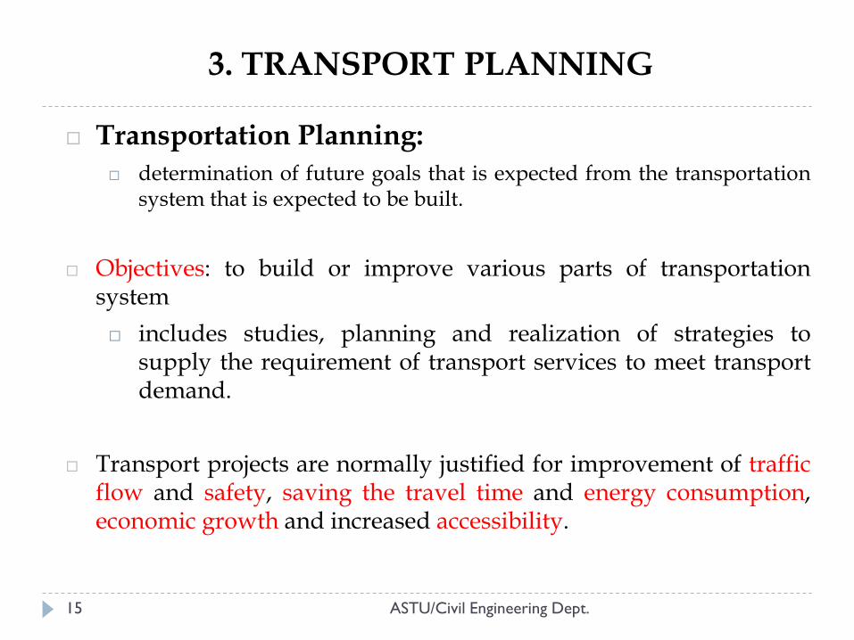
Transportation Planning:
determination of future goals that is expected from the transportation system that is expected to be built.
Objectives: to build or improve various parts of transportation system
includes studies, planning and realization of strategies to supply the requirement of transport services to meet transport demand.
Transport projects are normally justified for improvement of traffic flow and safety, saving the travel time and energy consumption, economic growth and increased accessibility.
ASTU/Civil Engineering Dept.
Basic Elements of Transportation Planning
16
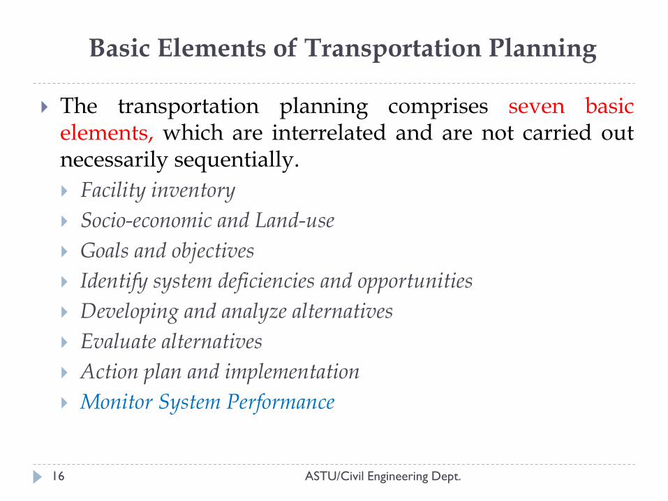
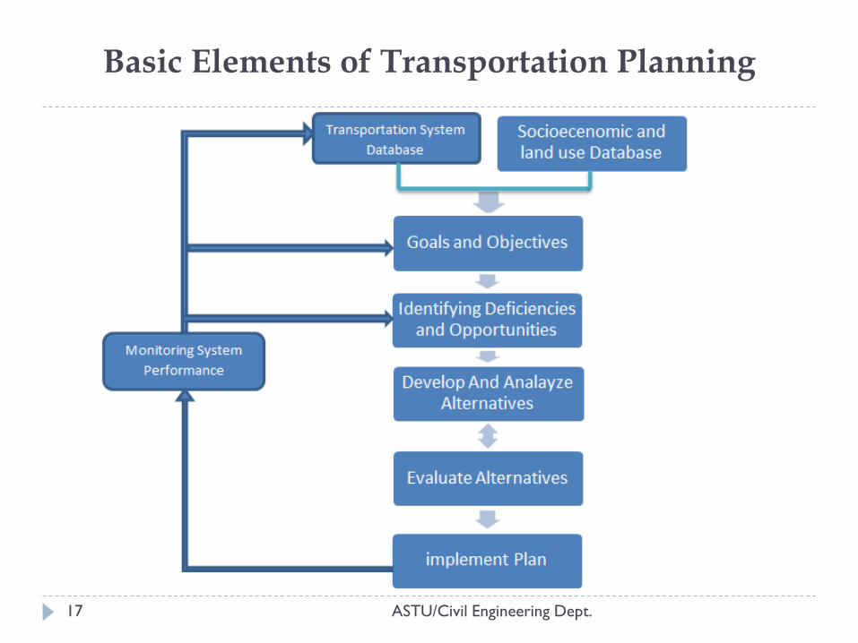
The transportation planning comprises seven basic elements, which are interrelated and are not carried out necessarily sequentially.
Facility inventory
Socio-economic and Land-use
Goals and objectives
Identify system deficiencies and opportunities
Developing and analyze alternatives
Evaluate alternatives
Action plan and implementation
Monitor System Performance
ASTU/Civil Engineering Dept.
ASTU/Civil Engineering Dept. 17
Basic Elements of Transportation Planning
Basic Elements of Transportation Planning 1. Facility inventory
18
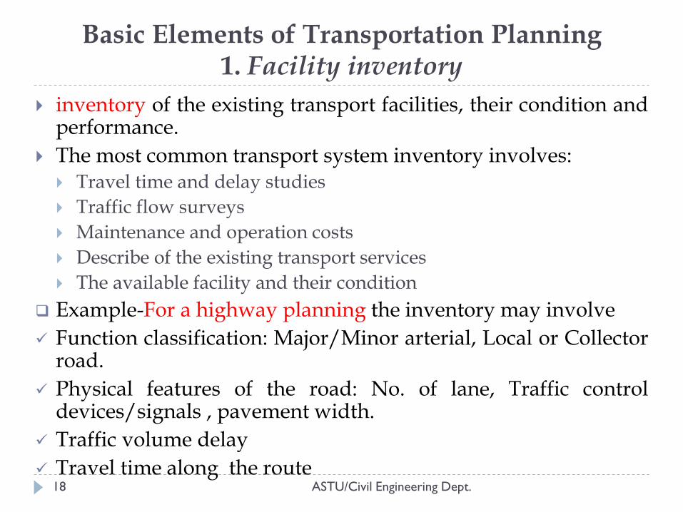
inventory of the existing transport facilities, their condition and performance.
The most common transport system inventory involves: Travel time and delay studies
Traffic flow surveys
Maintenance and operation costs
Describe of the existing transport services
The available facility and their condition
Example-For a highway planning the inventory may involve
Function classification: Major/Minor arterial, Local or Collector road.
Physical features of the road: No. of lane, Traffic control devices/signals , pavement width.
Traffic volume delay
Travel time along the route
ASTU/Civil Engineering Dept.
19
involves all the activities required to understand the situation that give rise to the perceived need for a transportation improvement.
considered which relates trip making to the type of activities that occur in a region and also to the characteristics of the trip maker that will influence the way this trips are made.
The type of data on trip maker characteristics include: Level of income Number of members in house hold Number of vehicles in house hold Age composition of house hold Education level Employment etc.
Examples of land use: shopping center, industrial areas, residential areas, Offices etc…
Basic Elements of Transportation Planning
2. Socio-economic and Land-use
ASTU/Civil Engineering Dept.
20
Goals are generalized statements that indicate the desired achievement of transportation plan.
Objectives are more specific statements that indicate the means by which these goals will be achieved.
Examples: Goals: “The transportation system should meet the mobility needs
of the population” Objectives: “Provide transit service to major markets in the
region.” To identify objectives and related problems there are two types of
approaches The problem oriented approach: starts with defining problem The objective-led approach: starts with defining objectives and indicators
Some of the possible set of objectives: Safety Accessibility: ease of reaching: Sustainability Environmental protection Economic efficiency Economic regeneration
Basic Elements of Transportation Planning 3. Goals and objectives
ASTU/Civil Engineering Dept.
21
Transport planning identifies and prioritizes those elements of transport systems where problems exist today or where problems exist in further given growth in travel.
Also transport planning can also identify areas where significant problem do not exist this time, but system can provide opportunities for enhanced efficiency of operation.
Basic Elements of Transportation Planning 4. Identify system deficiencies and opportunities
ASTU/Civil Engineering Dept.
22
Consideration is given to a variety of ideas, designs, locations, and system configurations that might provide solutions to the problems.
include preliminary feasibility studies, data gathering field testing and cost estimating may be necessary at this stage to determine the practicability and financial feasibility of the alternative being proposed.
Example- Improvement of highways
New construction
Adding new lanes
Improving traffic controls through signals, signs etc.
Improving traffic flow through canalization.
Basic Elements of Transportation Planning 5. Developing and analyze alternatives
ASTU/Civil Engineering Dept.
23
Determine how well each alternative achieve the objectives of the project as defined by the criteria.
Evaluation involves methods for comparing in an analytic way relative value of the alternatives.
Mostly used approaches is the benefit/cost ratio.
The benefit cost ratio is the means of identifying the most economical efficient alternative by defining benefits and costs.
Basic Elements of Transportation Planning 6. Evaluate alternatives
ASTU/Civil Engineering Dept.
24
Once the transport project has been selected, a detail design phase begins, in which each of the components of the facility is specified.
this involves physical location, geometric dimension, and structural configuration.
Design plans are produced that can be used to estimate the cost of building the project.
Monitor System Performance Continually examines the performance and condition of the
transportation system to identify where improvements can be made.
necessary to systematically identify areas where improvements might occur.
Basic Elements of Transportation Planning 7. Action plan and implementation
ASTU/Civil Engineering Dept.

Thank You!
ASTU/Civil Engineering Dept.
QUESTIONS?
25

Highway Engineering-I
Chapter Two:
HIGHWAY ROUTE SURVEYS AND LOCATION
ASTU/Civil Engineering Dept.
Instructor: Fasika Mekonnen
1
1. HIGHWAY ALIGNMENT
ASTU/Civil Engineering Dept.
Objective: establishment of the new highway’s centerline
and cross-sections in relation to the terminal points and to
the topography through which the highway will pass.
Centerline determines the amount of cut and fill, cross-
section details, drainage design, construction costs and
environmental impacts.
Improper alignment would increase;
Construction cost
Land acquisition cost
Maintenance cost
Vehicle operation cost
Accident rate
2
HIGHWAY ALIGNMENT…(Cond..)
ASTU/Civil Engineering Dept.
Different types of highway have different needs.
Requirements of ideal alignment:
Short
Easy
Construction, maintenance, vehicle operation
Safe
low accident, stable foundation)
Economical
Initial cost, maintenance cost, operation cost
3
ASTU/Civil Engineering Dept.
Factors controlling alignment
Obligatory points
Traffic
Geometric design
Economics
Other considerations
2. FACTORS CONTROLLING ALIGNMENT
4
FACTORS CONTROLLING ALIGNMENT..(Cond..)
ASTU/Civil Engineering Dept.
Obligatory points
Points through which the alignment is to pass
Bridges sites
Intermediate town b/n terminals
Mountainous pass
Points through which the alignment should not pass
Very costly structures
Highly developed expensive land areas
Cultural or religious places
Hospitals, schools etc
5
FACTORS CONTROLLING ALIGNMENT..(Cond..)
ASTU/Civil Engineering Dept.
Traffic
The alignment should suit traffic demand
The alignment should kept in view of the desire lines, flow patterns and future trend
Geometric design:
Grades, radius of curves, sight distance etc
First determine standard of the road and then
Fix the geometric standards
Economy:
Includes the initial cost, maintenance cost and operation cost
If high embankment and deep cuts are avoided there would be a decrease in initial cost
In minor roads: Grades-steep, Curves-sharp
6
FACTORS CONTROLLING ALIGNMENT..(Cond..)
ASTU/Civil Engineering Dept.
Other considerations:
Drainage consideration
Guide the vertical alignment
Hydrological factors
Subsurface water level, seepage flow, high flood level
Political considerations
7
3. ROUTE SURVEY
ASTU/Civil Engineering Dept.
The purpose of the route survey is to fix the road
alignment i.e. to position the central line of the road
on the ground.
The work of the highway location survey may include
Desk study
Reconnaissance surveys
Preliminary surveys
Final location & detailed surveys
8
ROUTE SURVEY 1. Desk study
ASTU/Civil Engineering Dept. 9
ROUTE SURVEY 1. Desk study
ASTU/Civil Engineering Dept.
If the topographic map of the area is available it is
possible to suggest the likely routes of the road
The following details help to locate the routes:
Alignment avoiding valleys, ponds or lakes
Possibility of crossing through mountain pass
Approximate location of bridges sites for crossing
river
Consider alternate routes by keeping the
permissible gradient
10
ROUTE SURVEY 2. Reconnaissance surveys
ASTU/Civil Engineering Dept.
To examine the general character of the area
Helps to decide the most feasible routes for detailed
studies
A field survey party may inspect a fairly broad stretch
of land along the proposed alternatives routes of the
map in the field
All relevant details not available in the map are
collected & noted down
11
ROUTE SURVEY 2. Reconnaissance surveys (Cont..)
ASTU/Civil Engineering Dept.
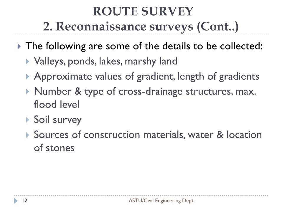
The following are some of the details to be collected:
Valleys, ponds, lakes, marshy land
Approximate values of gradient, length of gradients
Number & type of cross-drainage structures, max.
flood level
Soil survey
Sources of construction materials, water & location
of stones
12
ROUTE SURVEY 2. Reconnaissance surveys (Cont..)
ASTU/Civil Engineering Dept.
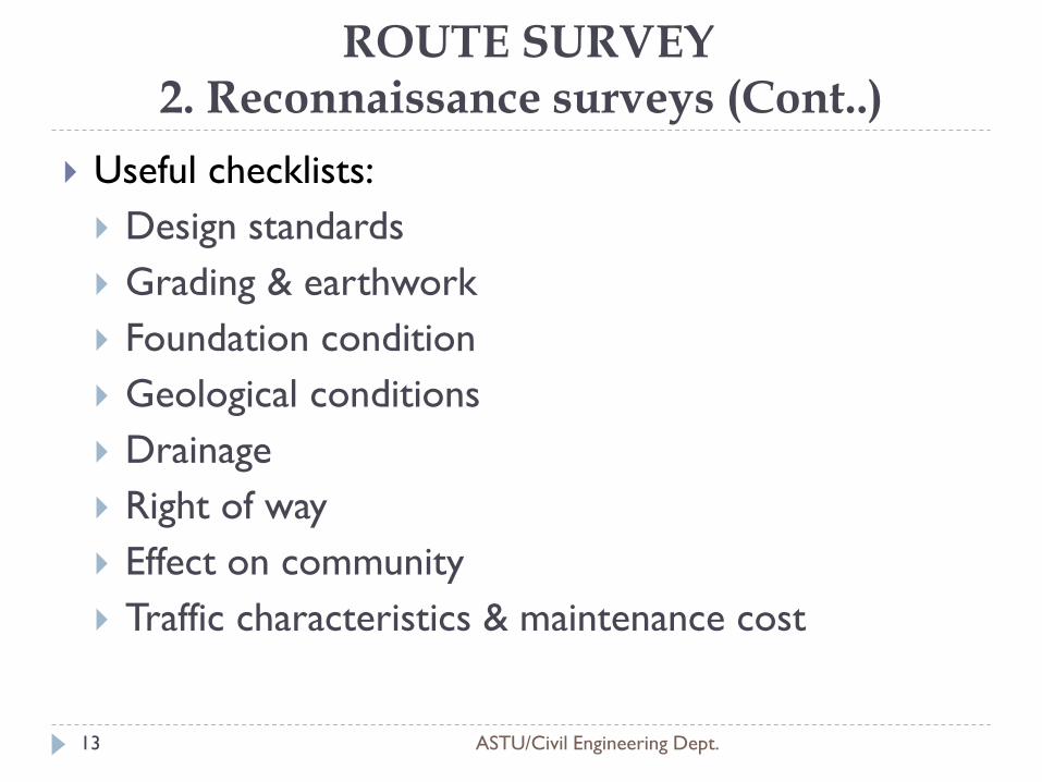
Useful checklists:
Design standards
Grading & earthwork
Foundation condition
Geological conditions
Drainage
Right of way
Effect on community
Traffic characteristics & maintenance cost
13
ROUTE SURVEY 3. Preliminary survey
ASTU/Civil Engineering Dept.
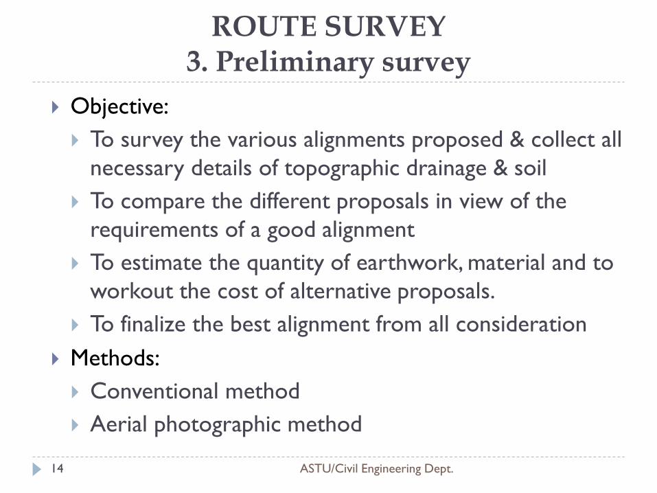
Objective:
To survey the various alignments proposed & collect all
necessary details of topographic drainage & soil
To compare the different proposals in view of the
requirements of a good alignment
To estimate the quantity of earthwork, material and to
workout the cost of alternative proposals.
To finalize the best alignment from all consideration
Methods:
Conventional method
Aerial photographic method
14
ROUTE SURVEY 3. Preliminary survey(cont..)
ASTU/Civil Engineering Dept.
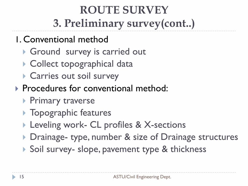
1. Conventional method
Ground survey is carried out
Collect topographical data
Carries out soil survey
Procedures for conventional method:
Primary traverse
Topographic features
Leveling work- CL profiles & X-sections
Drainage- type, number & size of Drainage structures
Soil survey- slope, pavement type & thickness
15
ROUTE SURVEY 3. Preliminary survey(cont..)
ASTU/Civil Engineering Dept.
2. Aerial photography method
It is a modern approach by taking aerial
photographs (proposed corridor) & using photo
interpretation technique to obtain the necessary
topographic, soil and geological data.
Then PS of various alternate alignments, a
comparative is made.
Finally the most suitable alignment is selected.
16
ROUTE SURVEY 4. Final location survey
ASTU/Civil Engineering Dept.
Purpose:
To fix the centerline of the selected alignment on the ground and
To collect additional data for the design and preparation of working drawings.
Features of the final location survey:
Pegging the center line
centerline leveling
X-section leveling
Intersecting road
The direction w.r.t the CL of all intersecting roads should be measured.
Profiles and x- section
Ditches and streams
Profile and X-section leveling helps for location and construction of culverts and bridges.
17
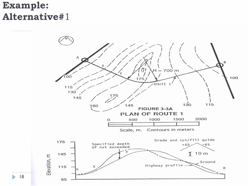
Example:
Alternative#1
ASTU/Civil Engineering Dept. 18
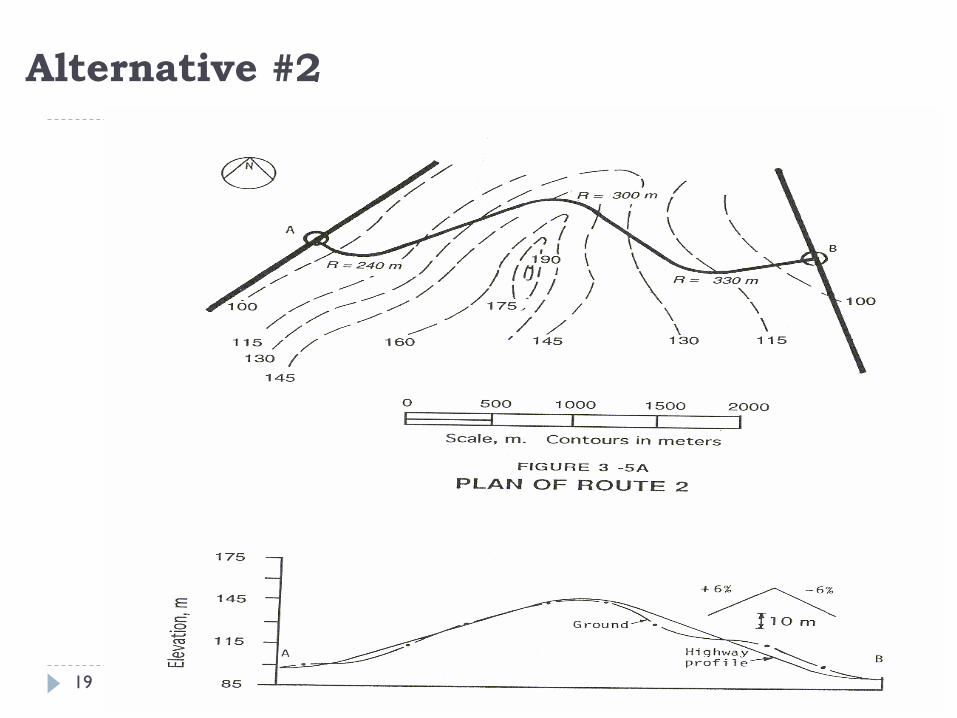
Alternative #2
ASTU/Civil Engineering Dept. 19
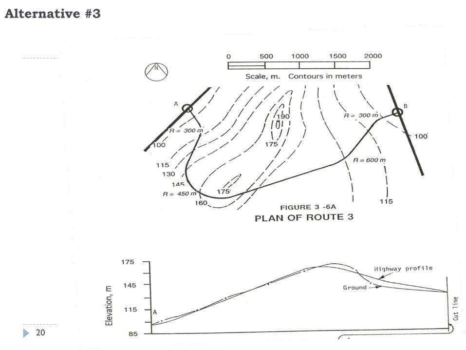
Alternative #3
ASTU/Civil Engineering Dept. 20
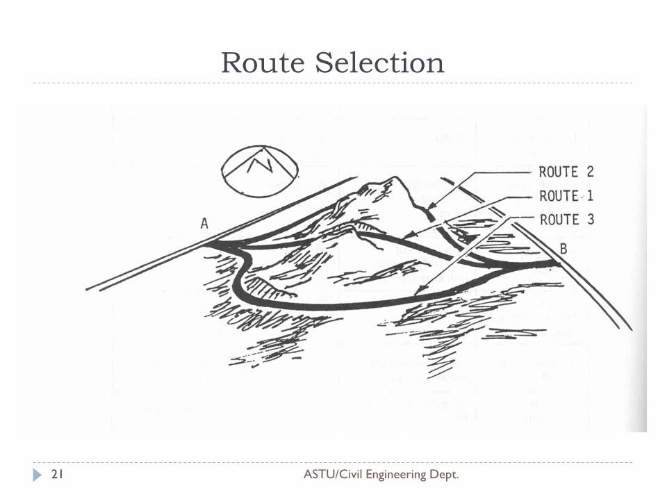
Route Selection
ASTU/Civil Engineering Dept. 21

Thank You!
ASTU/Civil Engineering Dept.
QUESTIONS?
22
Highway Engineering-I
Chapter Three:
GEOMETRICAL DESIGN OF HIGHWAY
ASTU/Civil Engineering Dept. 1
Instructor: Fasika Mekonnen
1. INTRODUCTION
ASTU/Civil Engineering Dept. 2
Highway geometric design is the process whereby the layout of the road through the terrain is designed to meet the needs of the road users.
Geometric features are the road cross-section and horizontal and vertical alignment.
highway geometric elements:
Cross-section
Horizontal alignment
Vertical alignment
Sight distance
Vertical and lateral clearance
Intersections
2. DESIGN CONTROL AND CRITERIA
ASTU/Civil Engineering Dept. 3
The choice of design controls and criteria is influenced by
the following factors:
the functional classification of the road;
the nature of the terrain;
the design vehicle;
the traffic volumes expected on the road;
the design speed;
the density and character of the adjoining land use;
economic and environmental considerations.
Functional Classification of Roads
ASTU/Civil Engineering Dept. 4
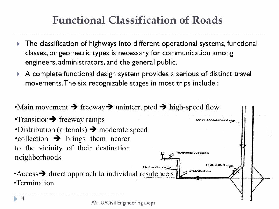
The classification of highways into different operational systems, functional
classes, or geometric types is necessary for communication among
engineers, administrators, and the general public.
A complete functional design system provides a serious of distinct travel
movements. The six recognizable stages in most trips include :
•Main movement freeway uninterrupted high-speed flow
•Transition freeway ramps
•Distribution (arterials) moderate speed
•collection brings them nearer
to the vicinity of their destination
neighborhoods
•Access direct approach to individual residence s
•Termination
Functional Classification of Roads…(cond..)
ASTU/Civil Engineering Dept. 5
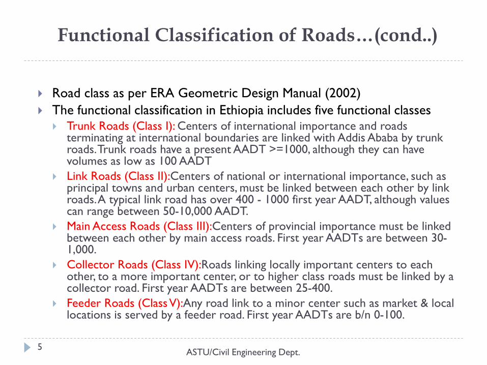
Road class as per ERA Geometric Design Manual (2002)
The functional classification in Ethiopia includes five functional classes Trunk Roads (Class I): Centers of international importance and roads
terminating at international boundaries are linked with Addis Ababa by trunk roads. Trunk roads have a present AADT >=1000, although they can have volumes as low as 100 AADT
Link Roads (Class II):Centers of national or international importance, such as principal towns and urban centers, must be linked between each other by link roads. A typical link road has over 400 - 1000 first year AADT, although values can range between 50-10,000 AADT.
Main Access Roads (Class III):Centers of provincial importance must be linked between each other by main access roads. First year AADTs are between 30-1,000.
Collector Roads (Class IV):Roads linking locally important centers to each other, to a more important center, or to higher class roads must be linked by a collector road. First year AADTs are between 25-400.
Feeder Roads (Class V):Any road link to a minor center such as market & local locations is served by a feeder road. First year AADTs are b/n 0-100.
Functional Classification of Roads…(cond..)
ASTU/Civil Engineering Dept. 6
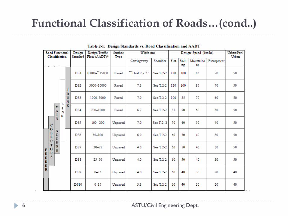
Functional Classification of Roads…(cond..)
ASTU/Civil Engineering Dept. 7
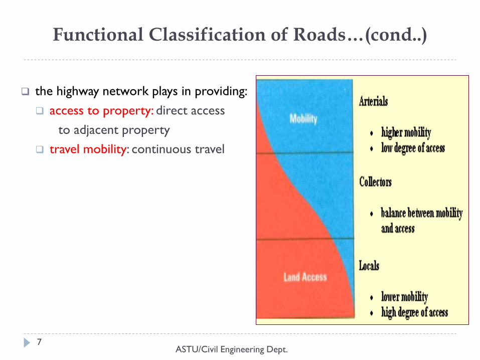
the highway network plays in providing:
access to property: direct access
to adjacent property
travel mobility: continuous travel
Functional Classification of Roads…(cond..)
ASTU/Civil Engineering Dept. 8
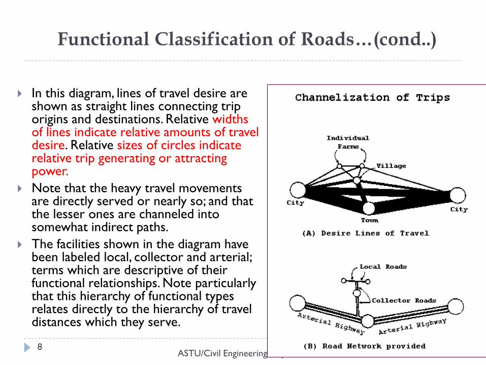
In this diagram, lines of travel desire are shown as straight lines connecting trip origins and destinations. Relative widths of lines indicate relative amounts of travel desire. Relative sizes of circles indicate relative trip generating or attracting power.
Note that the heavy travel movements are directly served or nearly so; and that the lesser ones are channeled into somewhat indirect paths.
The facilities shown in the diagram have been labeled local, collector and arterial; terms which are descriptive of their functional relationships. Note particularly that this hierarchy of functional types relates directly to the hierarchy of travel distances which they serve.
Topography and Land Use
ASTU/Civil Engineering Dept. 9
Topography, physical features and land use have a great effect on road locations and geometrics.
Design elements affected are:
Grades affected by hills,
Sight distance valleys, rivers
Cross-sections steep slopes
Speeds etc.
Ethiopian Road Authority classifies terrain as:
flat,
rolling,
mountainous and
escarpment.
Topography and Land Use…(cont.)
ASTU/Civil Engineering Dept. 10
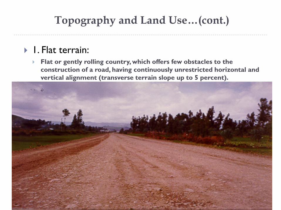
1. Flat terrain: Flat or gently rolling country, which offers few obstacles to the
construction of a road, having continuously unrestricted horizontal and
vertical alignment (transverse terrain slope up to 5 percent).
Topography and Land Use…(cont.)
ASTU/Civil Engineering Dept. 11
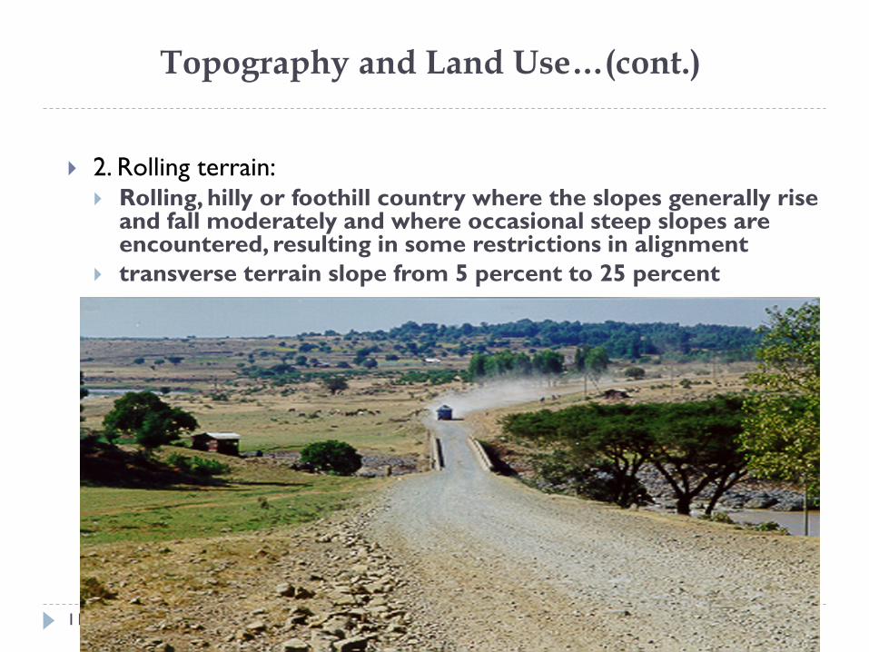
2. Rolling terrain: Rolling, hilly or foothill country where the slopes generally rise
and fall moderately and where occasional steep slopes are encountered, resulting in some restrictions in alignment
transverse terrain slope from 5 percent to 25 percent
Topography and Land Use…(cont.)
ASTU/Civil Engineering Dept. 12
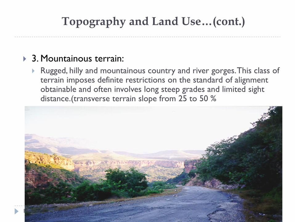
3. Mountainous terrain:
Rugged, hilly and mountainous country and river gorges. This class of terrain imposes definite restrictions on the standard of alignment obtainable and often involves long steep grades and limited sight distance.(transverse terrain slope from 25 to 50 %
Topography and Land Use…(cont.)
ASTU/Civil Engineering Dept. 13
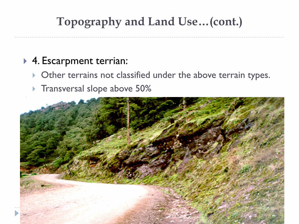
4. Escarpment terrian:
Other terrains not classified under the above terrain types.
Transversal slope above 50%
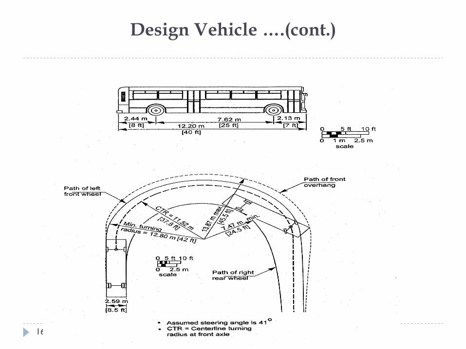
Design Vehicle
ASTU/Civil Engineering Dept. 14
Key controls in geometric highway design are the
physical characteristics and the proportions of vehicles of
various sizes using the highway and turning capabilities of
vehicles.
Controls in geometric design:
Max. gradient
Lane width
Horizontal curve Radius
Horizontal curve widening
Junction design
Design Vehicle ….(cont.)
ASTU/Civil Engineering Dept. 15
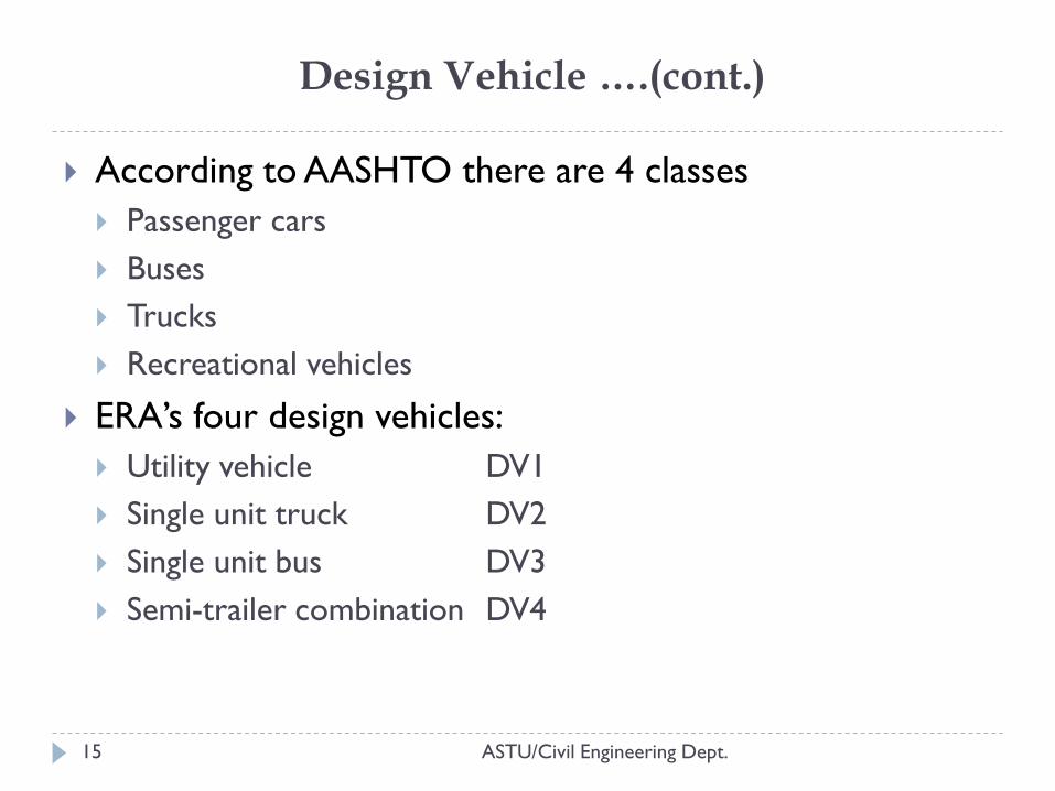
According to AASHTO there are 4 classes
Passenger cars
Buses
Trucks
Recreational vehicles
ERA’s four design vehicles:
Utility vehicle DV1
Single unit truck DV2
Single unit bus DV3
Semi-trailer combination DV4
Design Vehicle ….(cont.)
ASTU/Civil Engineering Dept. 16
Driver Characteristics
ASTU/Civil Engineering Dept. 17
Geometric design of a highway should consider users,
especially drivers’ performance limits. There are limits to
a driver’s vision, perception, reaction, concentration,
comfort that could impact the highway safety and
operating efficiency.
Example:
the average brake-reaction time of a driver (including decision
time), is 2.5 sec which important in determining sight distance
in highway geometric design
Design Volume
ASTU/Civil Engineering Dept. 18
Traffic volume is number of vehicles that pass a point along
a roadway during a specified time period.
directly affects features of design such as:
number of lanes, widths, alignments, and gradients.
Annual Average Daily Traffic (AADT): during a period of 24
consecutive hours averaged over a period of 365 days.
Average Daily Traffic (ADT): is the average of 24-hr counts
collected over a number of days greater than one but less
than a year.
one truck is often equivalent to several passenger cars.
Design Speed
ASTU/Civil Engineering Dept. 19
determine the various geometric design features of the roadway.
Depends on:
Functional classification
Land use of adjacent area
Topography
Expected operating speed
Select as high a design speed as practical
directly related:
Curvature(radius), superelevation, and sight distance
Indirectly related:
widths of lanes and shoulders and clearances to walls and rails.
3. HIGHWAY CROSS-SECTION ELEMENTS
ASTU/Civil Engineering Dept. 20
A cross-section will normally consist of the carriageway,
shoulders or curbs, drainage features, and earthwork
profiles
Carriageway- use by moving traffic: traffic lanes, auxiliary lanes,
climbing lanes, and passing lanes, and bus bays and lay-byes.
Roadway- consists of the carriageway and the shoulders,
parking lanes and viewing areas
Earthwork profiles- includes side slopes and back slopes
For urban cross-sections: facilities for pedestrians,
cyclists, or other specialist user groups
HIGHWAY CROSS-SECTION ELEMENTS…(cont.)
ASTU/Civil Engineering Dept. 21
Highways are categorized into Divided highways
Undivided highways The distinction is based on the presence of median
The components of divided highways within the right of way are Highway Travel Lanes
Shoulders
Medians
Pavement Crowns
Curbs
Drainage Ditches
Sideslopes
Guardrails
I. Highway Travel Lanes
ASTU/Civil Engineering Dept. 22
the portion of roadway provided for movement of vehicles
vary according to functional class of highway, design speed, traffic volume and level of development of the area.
Should accommodate the type & volume of traffic, assumed design speed
unequal-width lanes are used, locating the wider lane on the outside (right) provides more space for large vehicles that usually occupy that lane.
Example: Two-lane HW: 7.2m lane width
Table 2.1 of ERA manuals for all DS
II. Shoulders
ASTU/Civil Engineering Dept. 23
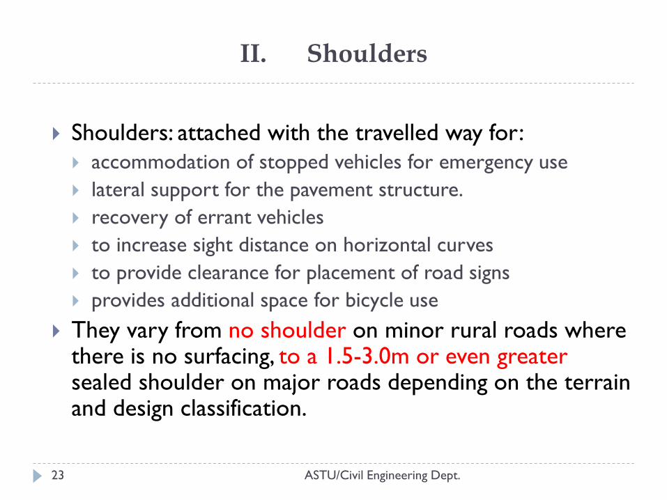
Shoulders: attached with the travelled way for:
accommodation of stopped vehicles for emergency use
lateral support for the pavement structure.
recovery of errant vehicles
to increase sight distance on horizontal curves
to provide clearance for placement of road signs
provides additional space for bicycle use
They vary from no shoulder on minor rural roads where there is no surfacing, to a 1.5-3.0m or even greater sealed shoulder on major roads depending on the terrain and design classification.
II. Shoulders…(cont.)
ASTU/Civil Engineering Dept. 24
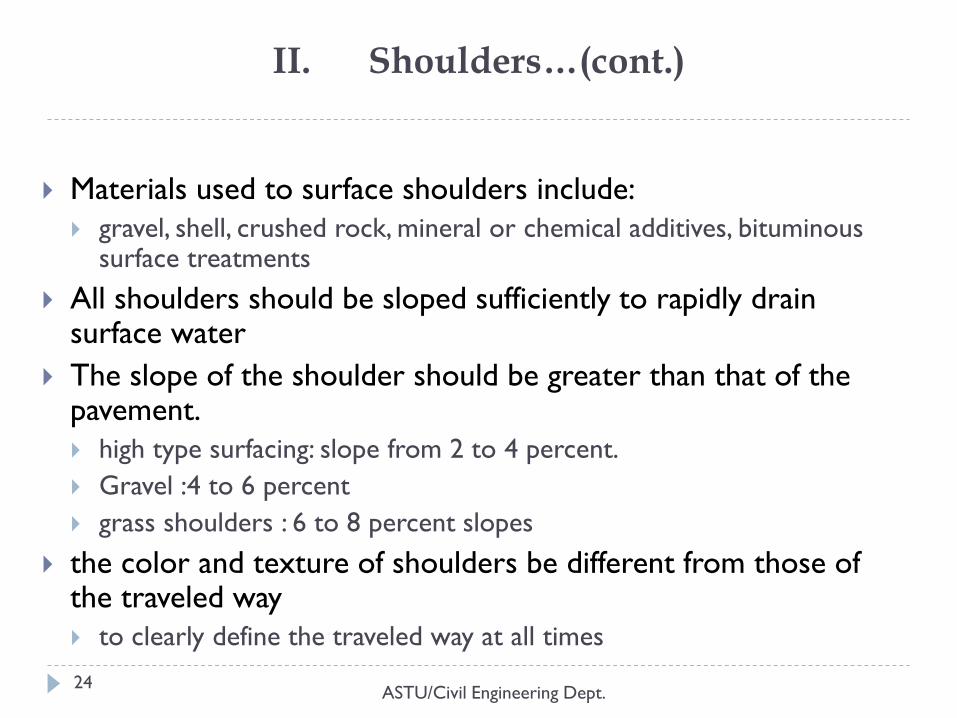
Materials used to surface shoulders include:
gravel, shell, crushed rock, mineral or chemical additives, bituminous surface treatments
All shoulders should be sloped sufficiently to rapidly drain surface water
The slope of the shoulder should be greater than that of the pavement.
high type surfacing: slope from 2 to 4 percent.
Gravel :4 to 6 percent
grass shoulders : 6 to 8 percent slopes
the color and texture of shoulders be different from those of the traveled way
to clearly define the traveled way at all times
II. Shoulders…(cont.)
ASTU/Civil Engineering Dept. 25
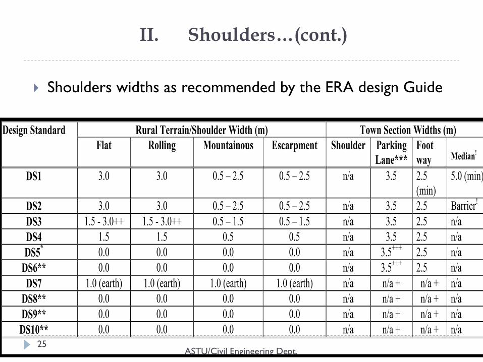
Shoulders widths as recommended by the ERA design Guide
Rural Terrain/Shoulder Width (m) Town Section Widths (m) Design Standard
Flat Rolling Mountainous Escarpment Shoulder Parking
Lane***
Foot
way
Median!
DS1 3.0 3.0 0.5 – 2.5 0.5 – 2.5 n/a 3.5 2.5
(min)
5.0 (min)
DS2 3.0 3.0 0.5 – 2.5 0.5 – 2.5 n/a 3.5 2.5 Barrier!
DS3 1.5 - 3.0++ 1.5 - 3.0++ 0.5 – 1.5 0.5 – 1.5 n/a 3.5 2.5 n/a
DS4 1.5 1.5 0.5 0.5 n/a 3.5 2.5 n/a
DS5* 0.0 0.0 0.0 0.0 n/a
3.5
+++ 2.5 n/a
DS6** 0.0 0.0 0.0 0.0 n/a 3.5+++
2.5 n/a
DS7 1.0 (earth) 1.0 (earth) 1.0 (earth) 1.0 (earth) n/a n/a + n/a + n/a
DS8** 0.0 0.0 0.0 0.0 n/a n/a + n/a + n/a
DS9** 0.0 0.0 0.0 0.0 n/a n/a + n/a + n/a
DS10** 0.0 0.0 0.0 0.0 n/a n/a + n/a + n/a
III. Medians
ASTU/Civil Engineering Dept. 26
Median is the portion of a highway separating opposing directions of the traveled way.
The principal functions: to separate opposing traffic
provide a recovery area for out of- control vehicles,
provide a stopping area in case of emergencies,
allow space for speed changes and storage of left-turning and U-turning vehicles,
minimize headlight glare, and
provide width for future lanes.
Additional benefits: in an urban area are that it may offer an open green space,
may provide a refuge area for pedestrians crossing the street, and
may control the location of intersection traffic conflicts.
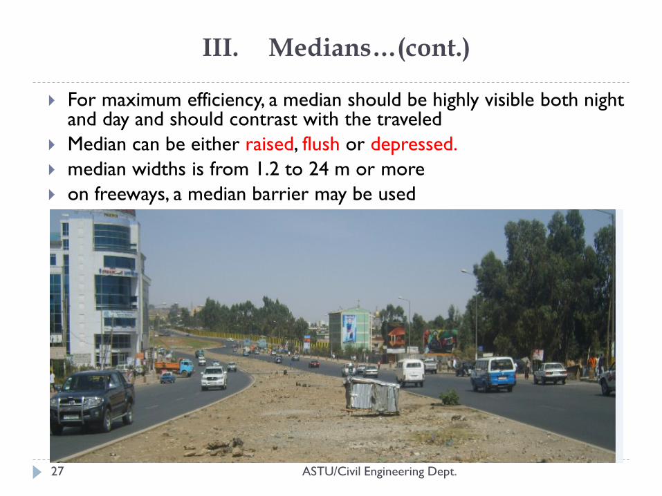
III. Medians…(cont.)
ASTU/Civil Engineering Dept. 27
For maximum efficiency, a median should be highly visible both night and day and should contrast with the traveled
Median can be either raised, flush or depressed.
median widths is from 1.2 to 24 m or more
on freeways, a median barrier may be used
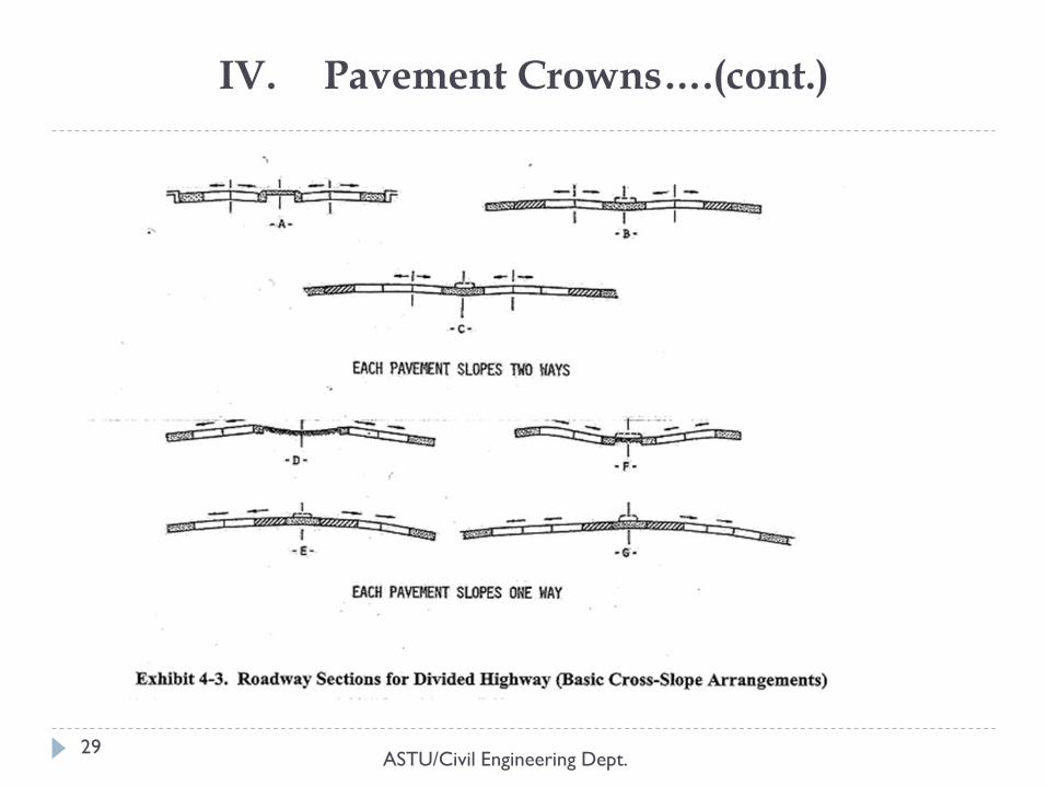
IV. Pavement Crowns
ASTU/Civil Engineering Dept. 28
Pavement crown is the raising of the centerline of the
roadway above the elevation of the pavement edges but
not being so great as to make steering difficult.
to provide adequate surface drainage
normal crossfall should be 2.5% on paved roads and 4 5%
on unpaved roads
Unpaved shoulders on a paved road should be 1.5 %
steeper
When four or more traffic lanes are used, it is advisable
to provide a higher rate of crown on the outer lanes
IV. Pavement Crowns….(cont.)
ASTU/Civil Engineering Dept. 29
V. Curbs
ASTU/Civil Engineering Dept. 30
A curb is a steep raised element at the edge of roadway.
functions:
drainage control, roadway edge delineation,
right-of-way reduction, aesthetics,
delineation of pedestrian walkways,
reduction of maintenance operations, and
assistance in orderly roadside development.
high-speed rural highways: at the outside edge of the
shoulder
V. Curbs..(cont.)
ASTU/Civil Engineering Dept. 31
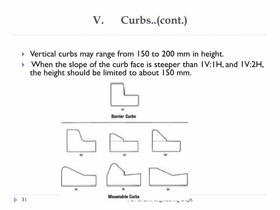
Vertical curbs may range from 150 to 200 mm in height.
When the slope of the curb face is steeper than 1V:1H, and 1V:2H, the height should be limited to about 150 mm.
VI. Drainage Ditches
ASTU/Civil Engineering Dept. 32
function of collecting and conveying surface water from
the highway right-of-way.
have adequate capacity for the design runoff
The depth of channel should be sufficient to remove
surface water without saturation of the subgrade
minimum desirable grade: drainage velocities needed to
avoid sedimentation
Generally, a broad, flat, rounded ditch section has been
found to be safer
VII. Sideslopes
ASTU/Civil Engineering Dept. 33
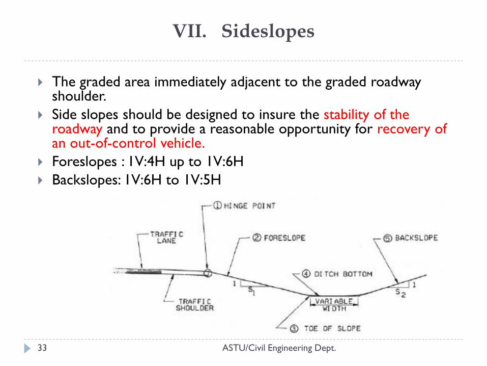
The graded area immediately adjacent to the graded roadway shoulder.
Side slopes should be designed to insure the stability of the roadway and to provide a reasonable opportunity for recovery of an out-of-control vehicle.
Foreslopes : 1V:4H up to 1V:6H
Backslopes: 1V:6H to 1V:5H
VIII. Guardrails
ASTU/Civil Engineering Dept. 34
A guardrail is provided where:
fills are over 2.4 m in height,
shoulder slopes are greater than 1V:4H,
there is sudden change in alignment,
great reduction in speed is necessary.
deep roadside ditches, steep banks,
right-of-way limitations,
Guardrails (roadside barriers) should be located beyond
the edge of the shoulder to ensure that the full shoulder
width may be used.
4. SIGHT DISTANCE
ASTU/Civil Engineering Dept. 35
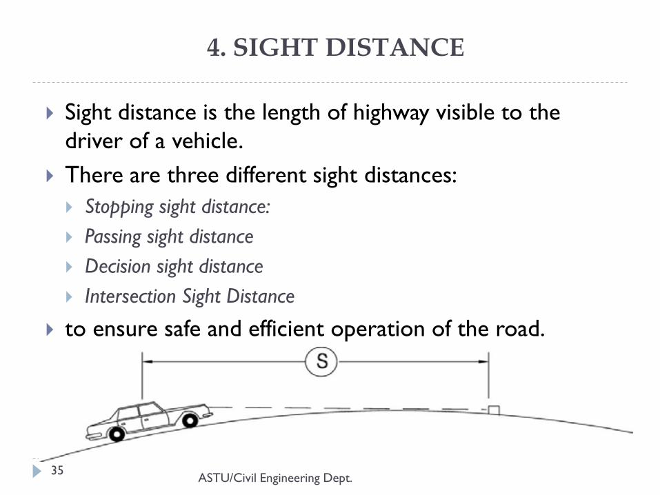
Sight distance is the length of highway visible to the
driver of a vehicle.
There are three different sight distances:
Stopping sight distance:
Passing sight distance
Decision sight distance
Intersection Sight Distance
to ensure safe and efficient operation of the road.
SIGHT DISTANCE..(cont.)
ASTU/Civil Engineering Dept. 36
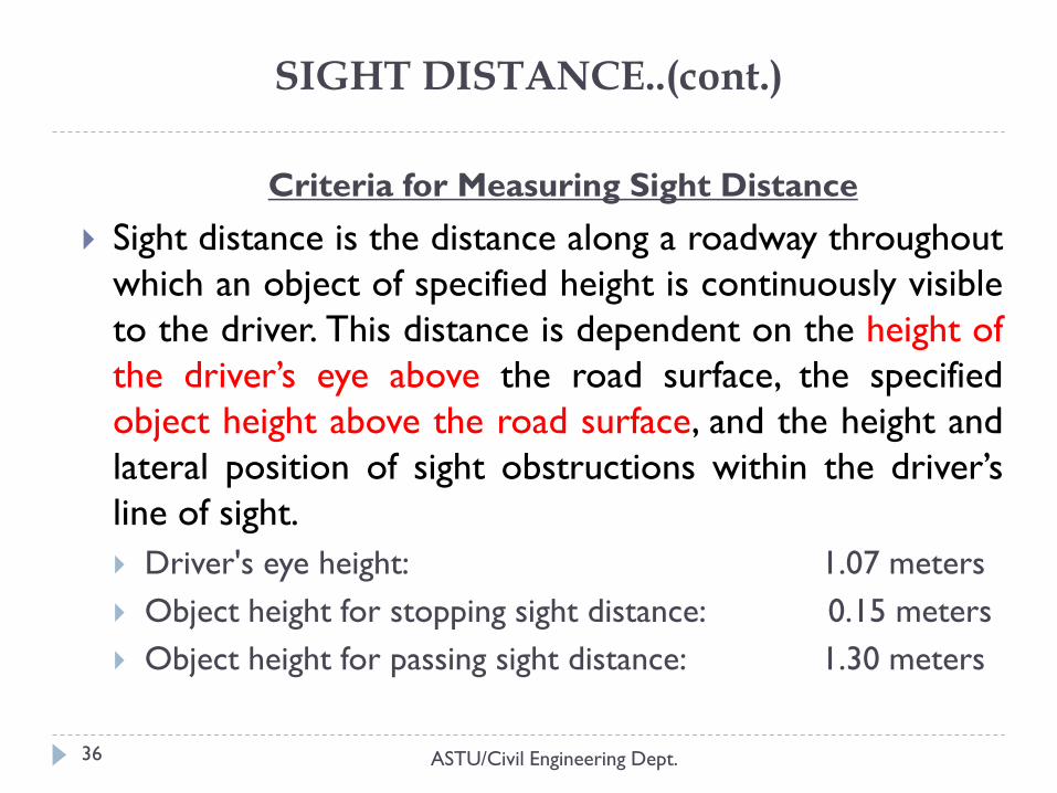
Criteria for Measuring Sight Distance
Sight distance is the distance along a roadway throughout
which an object of specified height is continuously visible
to the driver. This distance is dependent on the height of
the driver’s eye above the road surface, the specified
object height above the road surface, and the height and
lateral position of sight obstructions within the driver’s
line of sight.
Driver's eye height: 1.07 meters
Object height for stopping sight distance: 0.15 meters
Object height for passing sight distance: 1.30 meters
1. Stopping Sight Distance
ASTU/Civil Engineering Dept. 37
Stopping sight distance is the minimum distance required
to stop a vehicle traveling near a design speed before it
reaches a stationary object in the vehicle’s path.
The minimum stopping is based on the sum of two
distances:
brake reaction distance
the distance traversed by the vehicle from the instant the driver sights
an object necessitating a stop to the instant the brakes are applied
braking distance
the distance needed to stop the vehicle from the instant brake
application begins
1. Stopping Sight Distance…(cont.)
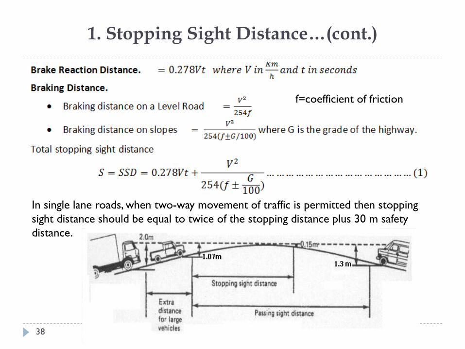
ASTU/Civil Engineering Dept. 38
In single lane roads, when two-way movement of traffic is permitted then stopping
sight distance should be equal to twice of the stopping distance plus 30 m safety
distance.
f=coefficient of friction
2. Passing Sight Distance
ASTU/Civil Engineering Dept. 39
Passing Sight Distance is the minimum sight distance on two-way single roadway roads that must be available to enable the driver of one vehicle to pass another vehicle safely without interfering with the speed of an oncoming vehicle traveling at the design speed.
assumptions about driver behavior. The overtaken vehicle travels at uniform speed.
The passing vehicle has reduced speed and trails the overtaken vehicle as it enters a passing section.
When the passing section is reached, the passing driver needs a short period of time to perceive the clear passing section and to react to start his or her maneuver.
Passing is accomplished under what may be termed a delayed start and a hurried return in the face of opposing traffic. The passing vehicle accelerates during the maneuver, and its average speed during the occupancy of the left lane is 15 km/h [10 mph] higher than that of the overtaken vehicle.
When the passing vehicle returns to its lane, there is a suitable clearance length between it and an oncoming vehicle in the other lane.
2. Passing Sight Distance…(cont.)
ASTU/Civil Engineering Dept.
40
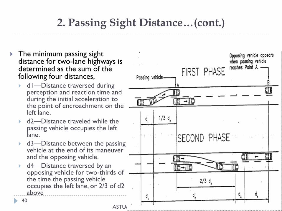
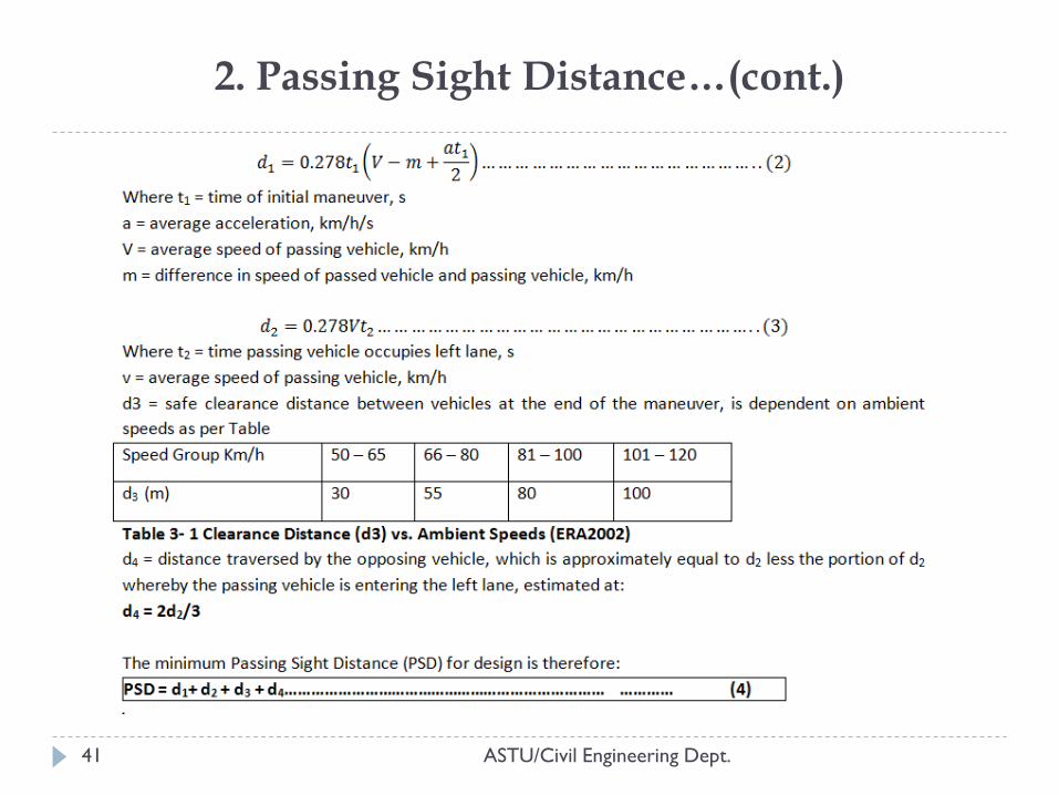
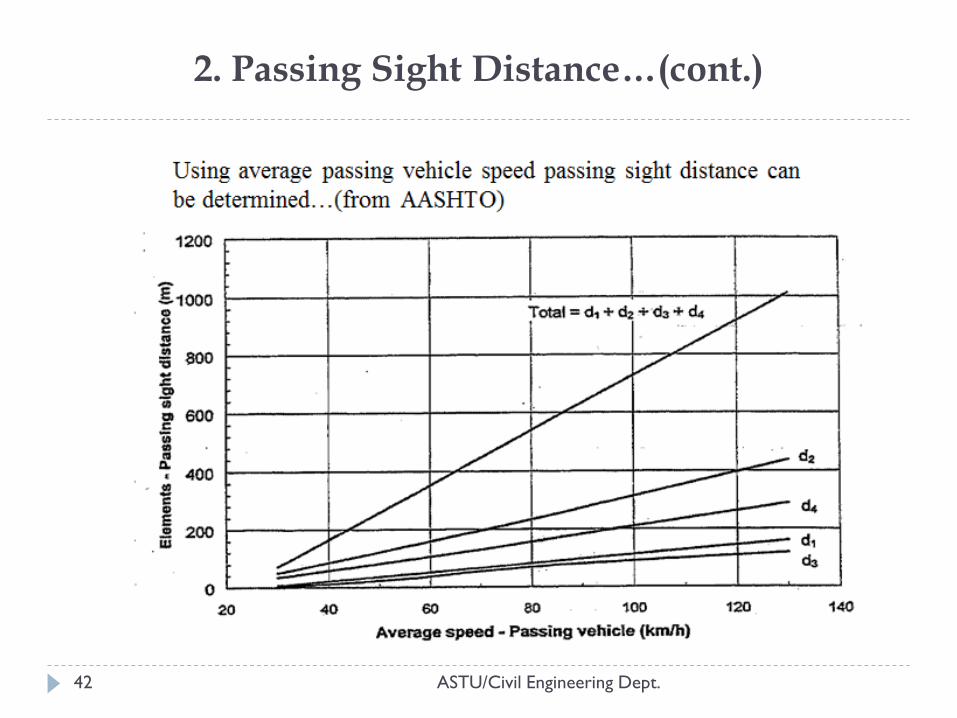
The minimum passing sight distance for two-lane highways is determined as the sum of the following four distances, d1—Distance traversed during
perception and reaction time and during the initial acceleration to the point of encroachment on the left lane.
d2—Distance traveled while the passing vehicle occupies the left lane.
d3—Distance between the passing vehicle at the end of its maneuver and the opposing vehicle.
d4—Distance traversed by an opposing vehicle for two-thirds of the time the passing vehicle occupies the left lane, or 2/3 of d2 above
2. Passing Sight Distance…(cont.)
ASTU/Civil Engineering Dept. 41
2. Passing Sight Distance…(cont.)
ASTU/Civil Engineering Dept. 42
3. Decision Sight Distance
ASTU/Civil Engineering Dept. 43
Decision sight distance is the distance needed for a driver to detect an unexpected or otherwise difficult-to-perceive information source or condition in a roadway environment then select an appropriate speed and path, and initiate and complete the maneuver safely and efficiently.
desirable to provide decision sight distance:
exit ramps,
diverging roadway terminals,
intersection stop bars,
changes in cross section,
Refer the table on your hand out
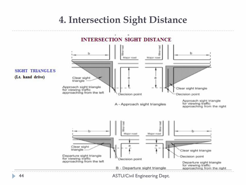
4. Intersection Sight Distance
ASTU/Civil Engineering Dept. 44
5. HORIZONTAL ALIGNMENT
ASTU/Civil Engineering Dept. 45
Horizontal alignment deals with the design of the directional transition of the highway in a horizontal plane.
Horizontal alignment includes the straight (tangent) sections of the roadway and circular curves that connect their change in direction
Why do we need horizontal curves: Terrain conditions, physical features, and right of way limitations
Depends: primarily on the design speed
type of curve,
friction,
super elevation and
widening of pavements on curves
Affects: safe vehicle operating speeds, sight distances, and opportunities for
phasing and highway capacity.
GENERAL CRITERIA
ASTU/Civil Engineering Dept. 46
Horizontal alignment should meet these general considerations: Alignment should be as straight as possible within physical and economic
constraints. A flowing line that conforming generally to the contours is always preferable from construction, maintenance and aesthetic point of view to the one with long tangents that slashes through the terrain.
Alignment should be consistent. Try to avoid sharp curves at the ends of long tangents and sudden changes from gently to sharply curving alignment.
Curves with small deflection angle (5o degrees or less) should be at least 150m (500ft) long and increased 30m (100ft) for every one-degree in deflection angle, to avoid the appearance of kink.
Avoid horizontal curvature on bridges when possible, however, when curvature is unavoidable, place the entire bridge on a single curve as flat as physical conditions permit. Ending or beginning curve on or near a bridge can present design and construction problems with super elevation transition.
Avoid ―Brocken-back‖ – short tangent section between two curves in the same direction.
DESIGN ELEMENTS IN HORIZONTAL ALIGNMENT
ASTU/Civil Engineering Dept. 47
I. Straight Line
provide the shortest distance between two established
control points
The following guidelines may apply concerning the length
of straights:-
Maximum length should not be greater than 20*Velocity (in
meter).
Minimum length should not greater than 2*Velocity for sight
distance.
In curves of the same direction intermediate straight lines
should be avoided or amounted to 6*Velocity.
DESIGN ELEMENTS IN HORIZONTAL ALIGNMENT..(cont.)
ASTU/Civil Engineering Dept. 48
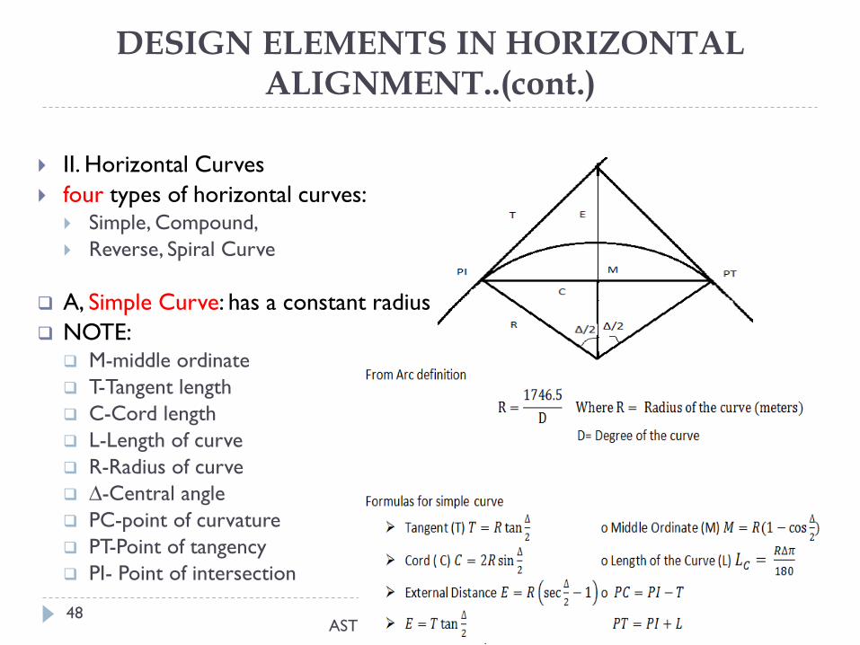
II. Horizontal Curves
four types of horizontal curves: Simple, Compound,
Reverse, Spiral Curve
A, Simple Curve: has a constant radius
NOTE: M-middle ordinate
T-Tangent length
C-Cord length
L-Length of curve
R-Radius of curve
∆-Central angle
PC-point of curvature
PT-Point of tangency
PI- Point of intersection
DESIGN ELEMENTS IN HORIZONTAL ALIGNMENT..(cont.)
ASTU/Civil Engineering Dept. 49
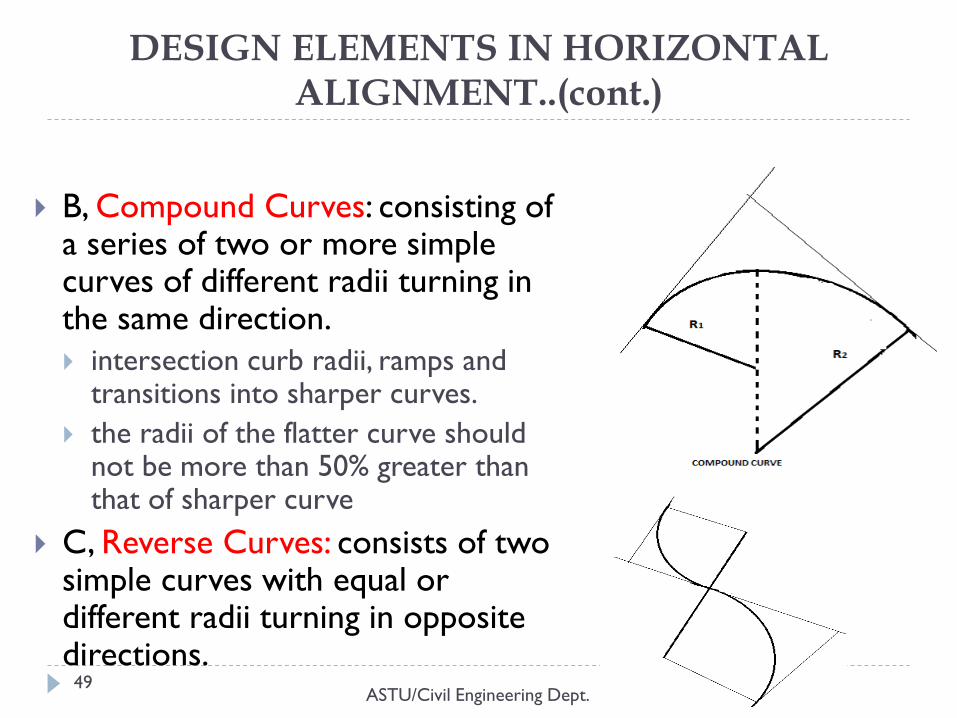
B, Compound Curves: consisting of a series of two or more simple curves of different radii turning in the same direction.
intersection curb radii, ramps and transitions into sharper curves.
the radii of the flatter curve should not be more than 50% greater than that of sharper curve
C, Reverse Curves: consists of two simple curves with equal or different radii turning in opposite directions.
DESIGN ELEMENTS IN HORIZONTAL ALIGNMENT..(cont.)
ASTU/Civil Engineering Dept. 50
D, Spiral Curves (Transition Curves): have got a radius of curvature gradually changing from infinity to the designed radius.
placed between tangents and circular curves or between two adjacent circular curves having substantially different radii.
Other type of curves: Brocken back, Switch back..
Reading assignment
Refer your surveying courses
SUPERELEVATION
ASTU/Civil Engineering Dept. 51
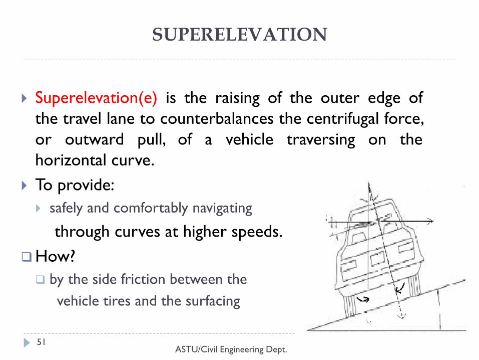
Superelevation(e) is the raising of the outer edge of
the travel lane to counterbalances the centrifugal force,
or outward pull, of a vehicle traversing on the
horizontal curve.
To provide:
safely and comfortably navigating
through curves at higher speeds.
How?
by the side friction between the
vehicle tires and the surfacing
SUPERELEVATION..(cont.)
ASTU/Civil Engineering Dept. 52
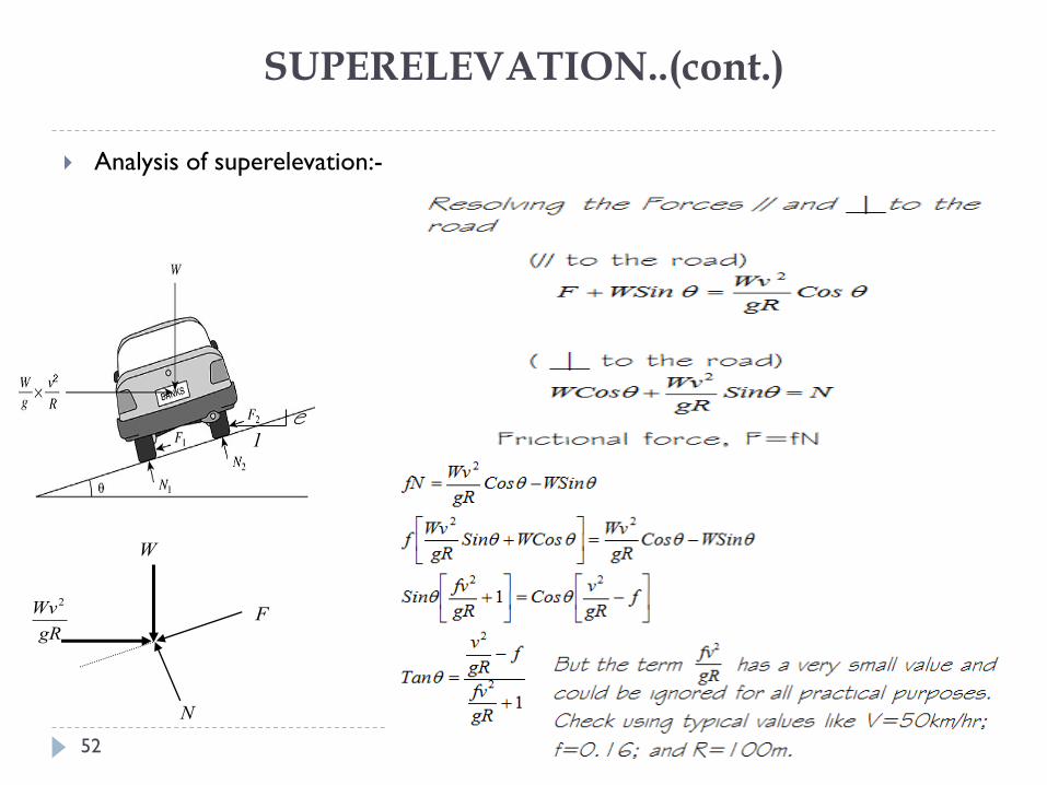
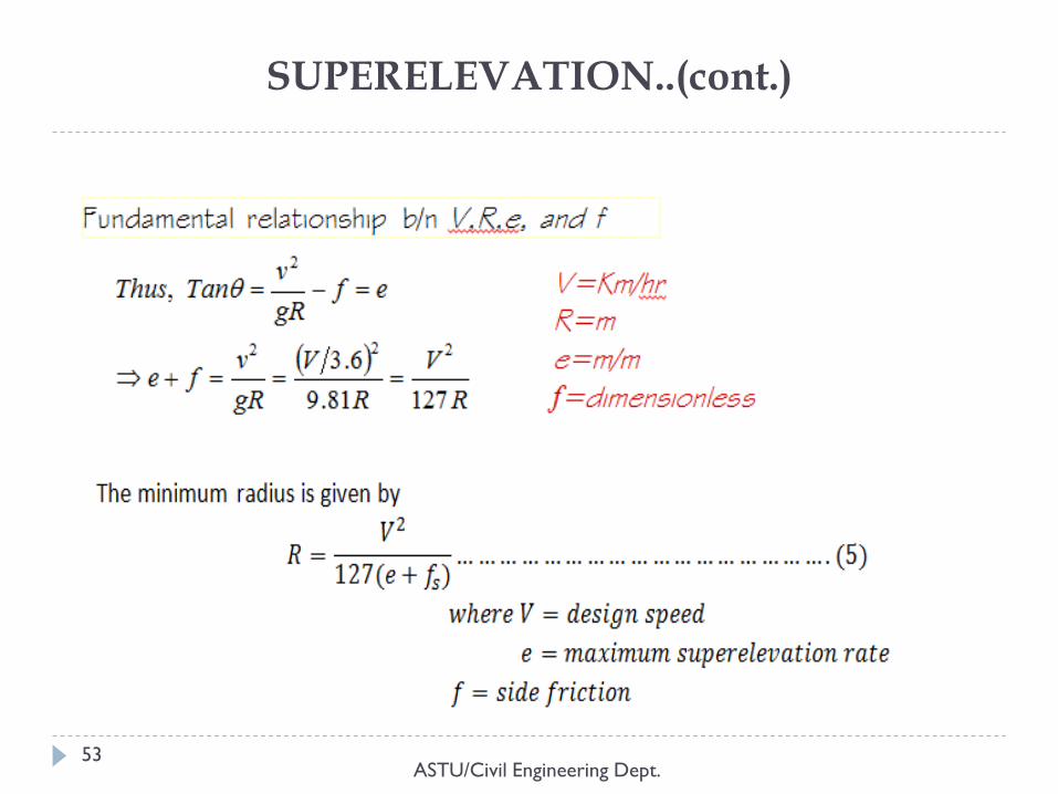
Analysis of superelevation:-
e
1
gR
Wv2
N
F
W
ASTU/Civil Engineering Dept. 53
SUPERELEVATION..(cont.)
SUPERELEVATION..(cont.)
ASTU/Civil Engineering Dept. 54
friction coefficients are dependent on:
vehicle speed, type, condition and texture of roadway surface,
weather conditions and type and condition of tires.
maximum rate of superelevation is controlled by four
factors:
climate conditions, terrain conditions, type of area and frequency of vey-
moving vehicles.
In summary
A rate of superelevation should not exceed 12%
A rate of 4 % or 6 % is applicable for urban design in areas with
little or no constraints.
As per ERA manual 4 % for urban and 8 % for rural.
SUPERLEVATION TRANSITION
ASTU/Civil Engineering Dept. 55
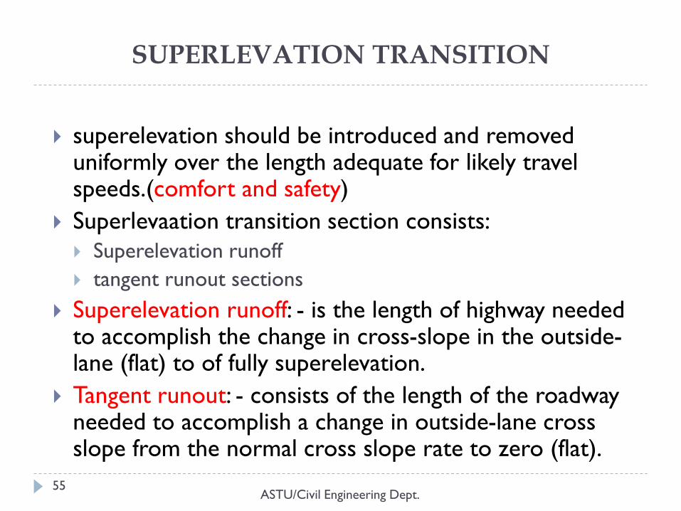
superelevation should be introduced and removed uniformly over the length adequate for likely travel speeds.(comfort and safety)
Superlevaation transition section consists:
Superelevation runoff
tangent runout sections
Superelevation runoff: - is the length of highway needed to accomplish the change in cross-slope in the outside-lane (flat) to of fully superelevation.
Tangent runout: - consists of the length of the roadway needed to accomplish a change in outside-lane cross slope from the normal cross slope rate to zero (flat).
ASTU/Civil Engineering Dept. 56
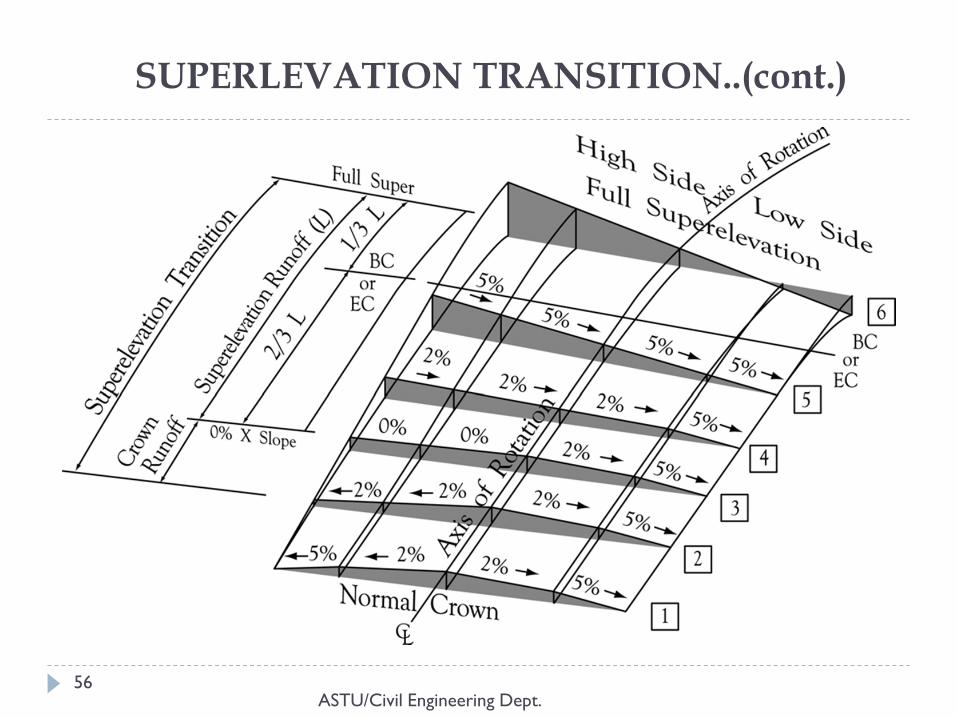
SUPERLEVATION TRANSITION..(cont.)
SUPERLEVATION TRANSITION..(cont.)
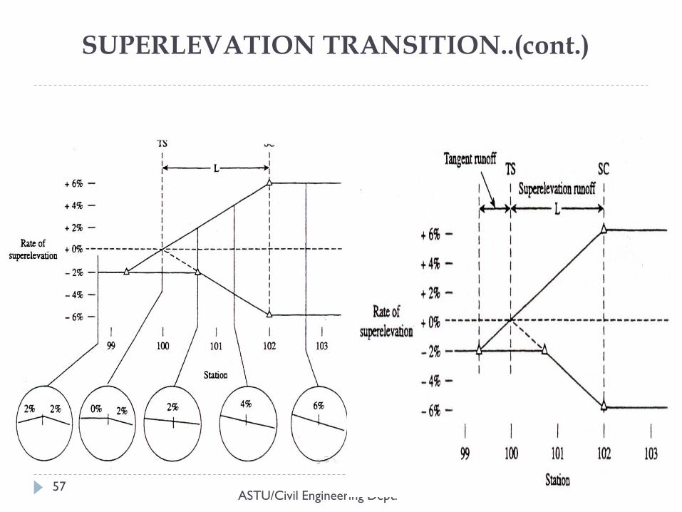
ASTU/Civil Engineering Dept. 57
SUPERLEVATION TRANSITION..(cont.)
ASTU/Civil Engineering Dept. 58
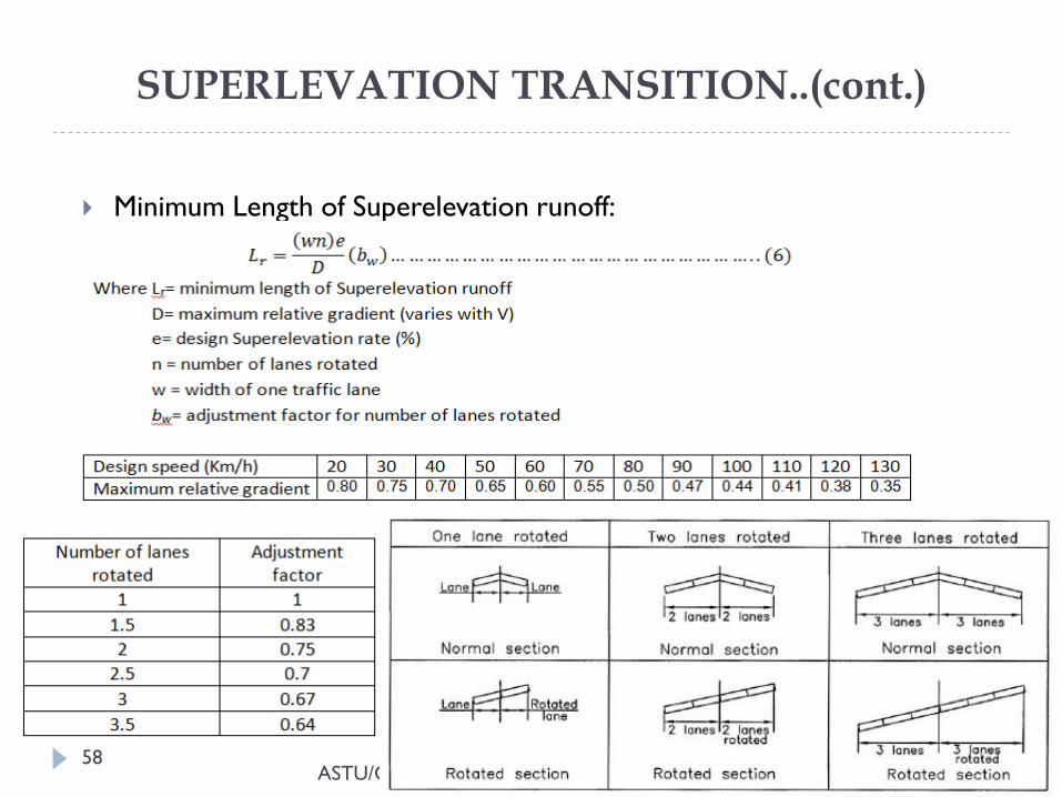
Minimum Length of Superelevation runoff:
SUPERLEVATION TRANSITION..(cont.)
ASTU/Civil Engineering Dept. 59
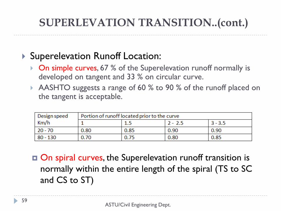
Superelevation Runoff Location: On simple curves, 67 % of the Superelevation runoff normally is
developed on tangent and 33 % on circular curve.
AASHTO suggests a range of 60 % to 90 % of the runoff placed on the tangent is acceptable.
On spiral curves, the Superelevation runoff transition is
normally within the entire length of the spiral (TS to SC
and CS to ST)
SUPERLEVATION TRANSITION..(cont.)
ASTU/Civil Engineering Dept. 60
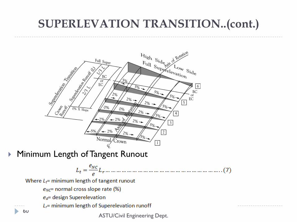
Minimum Length of Tangent Runout
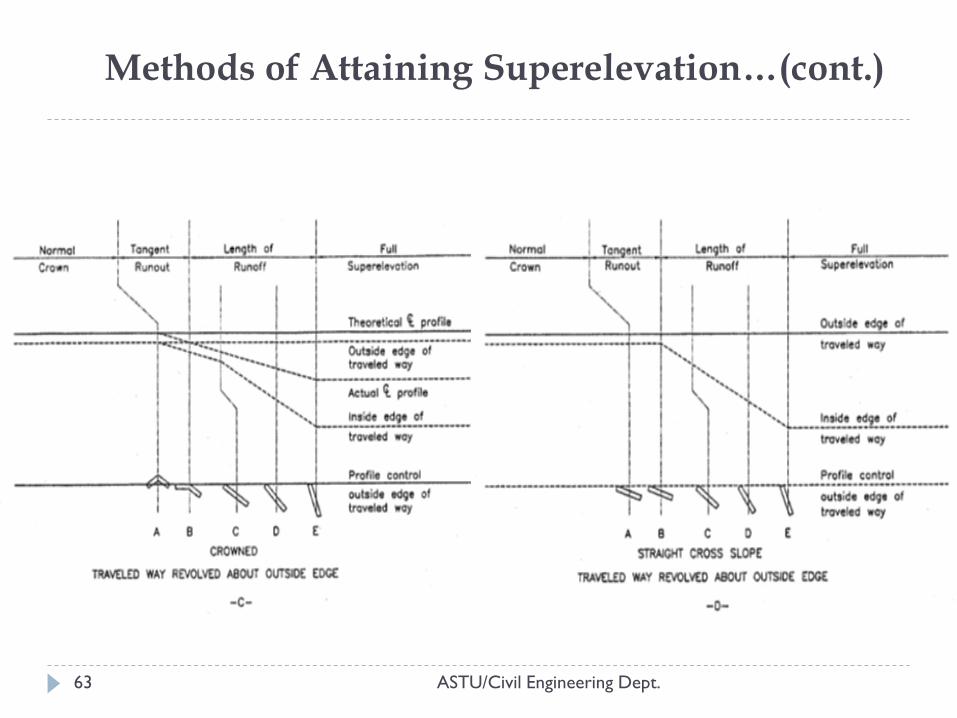
Methods of Attaining Superelevation
ASTU/Civil Engineering Dept. 61
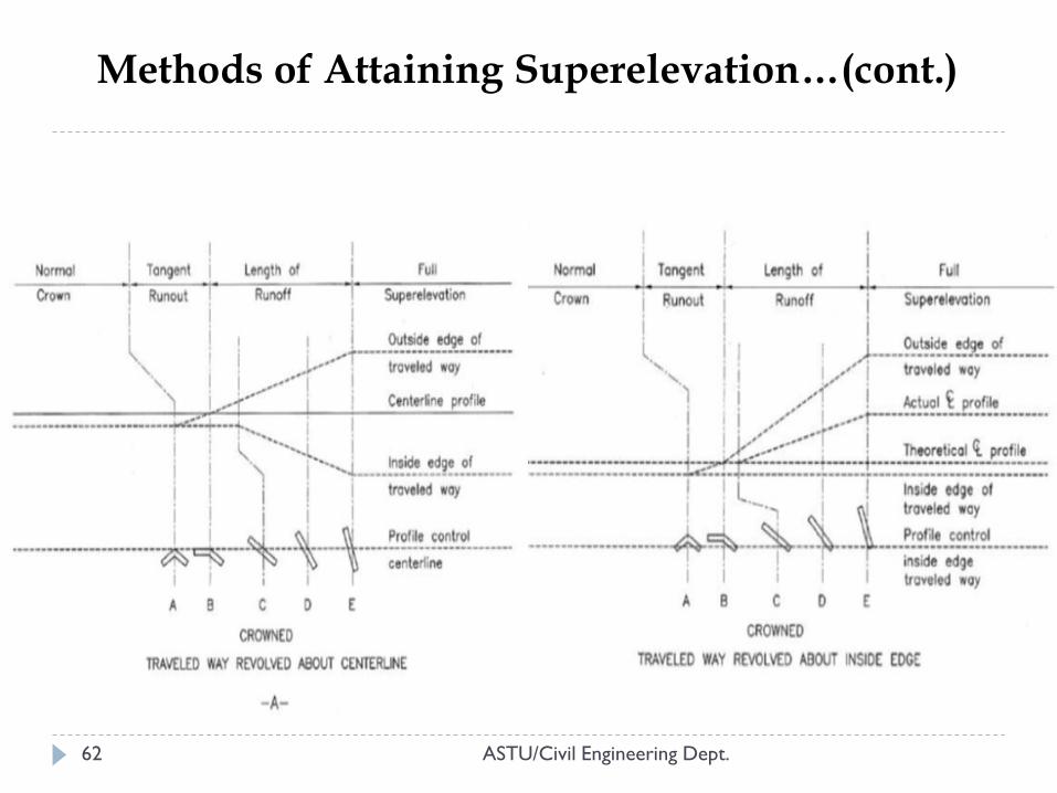
Four methods are used to transition the pavement to a
superelevated cross-section. These methods include
Revolving a travelled way with normal cross-slopes about the
centerline profile.
Revolving a traveled way with normal cross-slopes about the
inside-edge profile.
Revolving a travel way with normal cross-slope about the
outside-edge profile.
Revolving a straight cross-slope traveled way about the
outside-edge profile.
ASTU/Civil Engineering Dept. 62
Methods of Attaining Superelevation…(cont.)
Methods of Attaining Superelevation…(cont.)
ASTU/Civil Engineering Dept. 63
Axis of rotation with a Median
ASTU/Civil Engineering Dept. 64
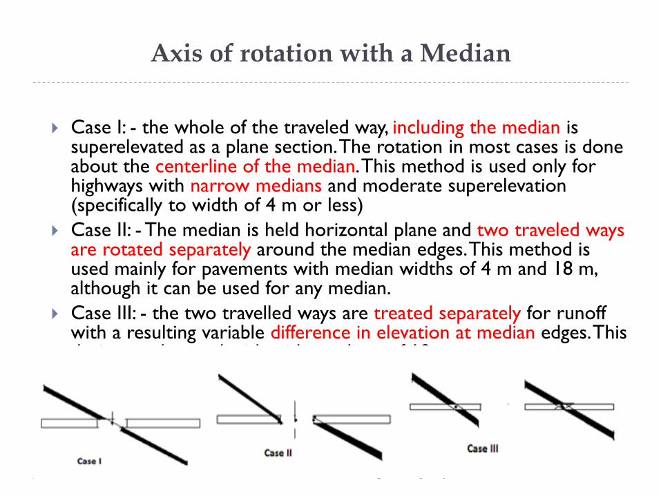
Case I: - the whole of the traveled way, including the median is superelevated as a plane section. The rotation in most cases is done about the centerline of the median. This method is used only for highways with narrow medians and moderate superelevation (specifically to width of 4 m or less)
Case II: - The median is held horizontal plane and two traveled ways are rotated separately around the median edges. This method is used mainly for pavements with median widths of 4 m and 18 m, although it can be used for any median.
Case III: - the two travelled ways are treated separately for runoff with a resulting variable difference in elevation at median edges. This design can be used with wide medians of 18 m or more.
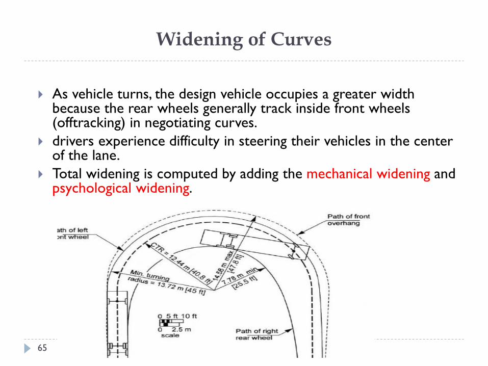
Widening of Curves
ASTU/Civil Engineering Dept. 65
As vehicle turns, the design vehicle occupies a greater width because the rear wheels generally track inside front wheels (offtracking) in negotiating curves.
drivers experience difficulty in steering their vehicles in the center of the lane.
Total widening is computed by adding the mechanical widening and psychological widening.
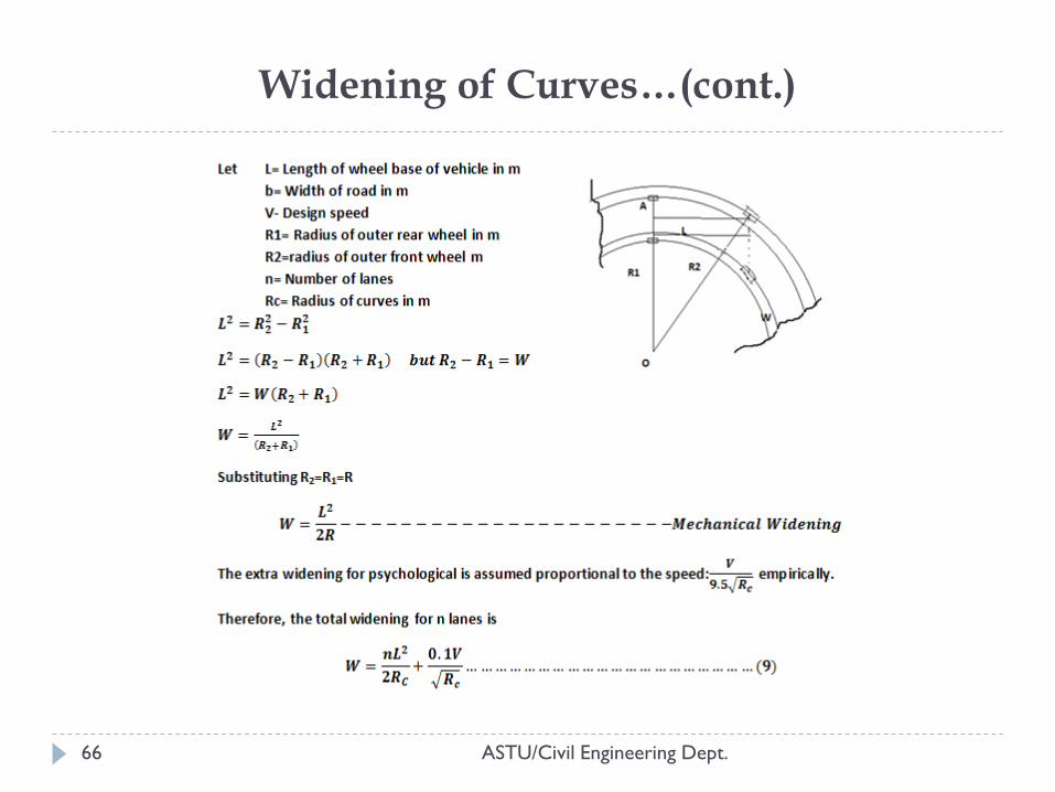
Widening of Curves…(cont.)
ASTU/Civil Engineering Dept. 66
STOPPING SIGHT DISTANCE ON HORIZONTAL CURVES
ASTU/Civil Engineering Dept. 67
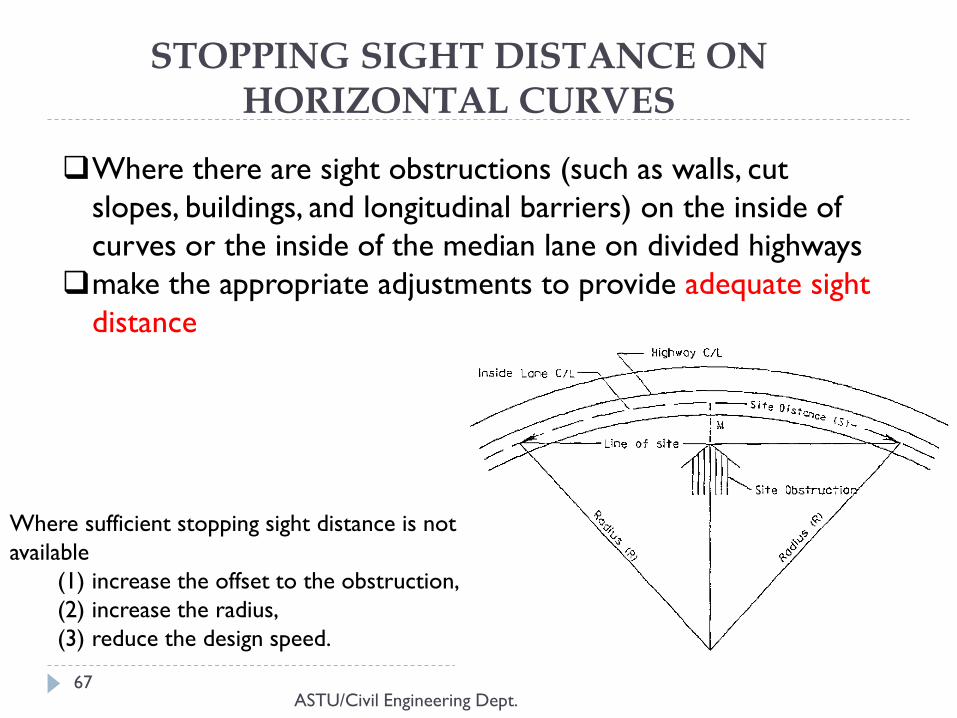
Where there are sight obstructions (such as walls, cut
slopes, buildings, and longitudinal barriers) on the inside of
curves or the inside of the median lane on divided highways
make the appropriate adjustments to provide adequate sight
distance
Where sufficient stopping sight distance is not
available
(1) increase the offset to the obstruction,
(2) increase the radius,
(3) reduce the design speed.
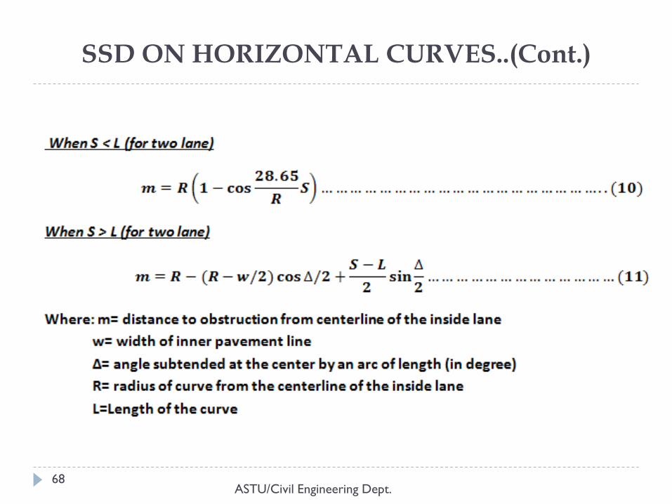
SSD ON HORIZONTAL CURVES..(Cont.)
ASTU/Civil Engineering Dept. 68
6. VERTICAL ALIGNMENT
ASTU/Civil Engineering Dept. 69
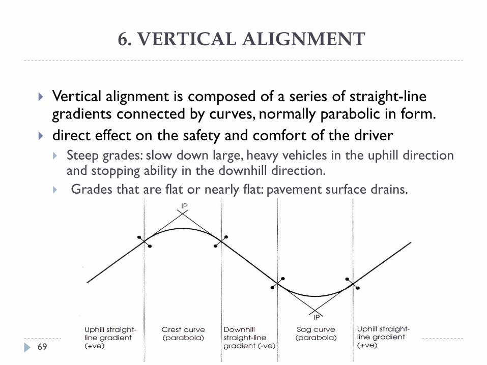
Vertical alignment is composed of a series of straight-line gradients connected by curves, normally parabolic in form.
direct effect on the safety and comfort of the driver
Steep grades: slow down large, heavy vehicles in the uphill direction and stopping ability in the downhill direction.
Grades that are flat or nearly flat: pavement surface drains.
VERTICAL CURVES
ASTU/Civil Engineering Dept. 70
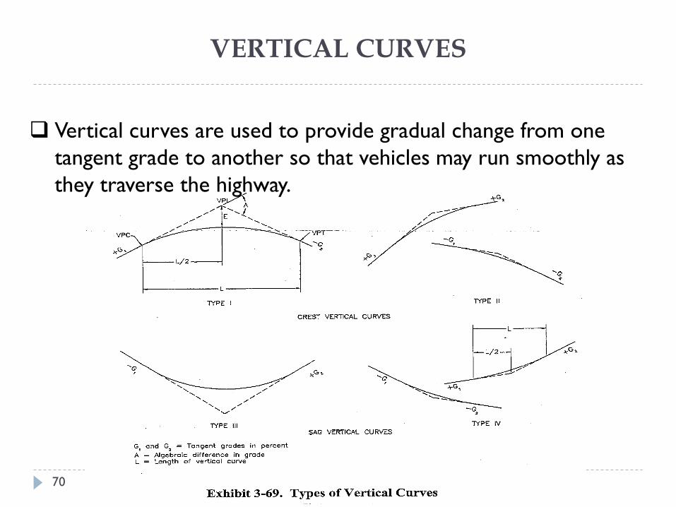
Vertical curves are used to provide gradual change from one
tangent grade to another so that vehicles may run smoothly as
they traverse the highway.
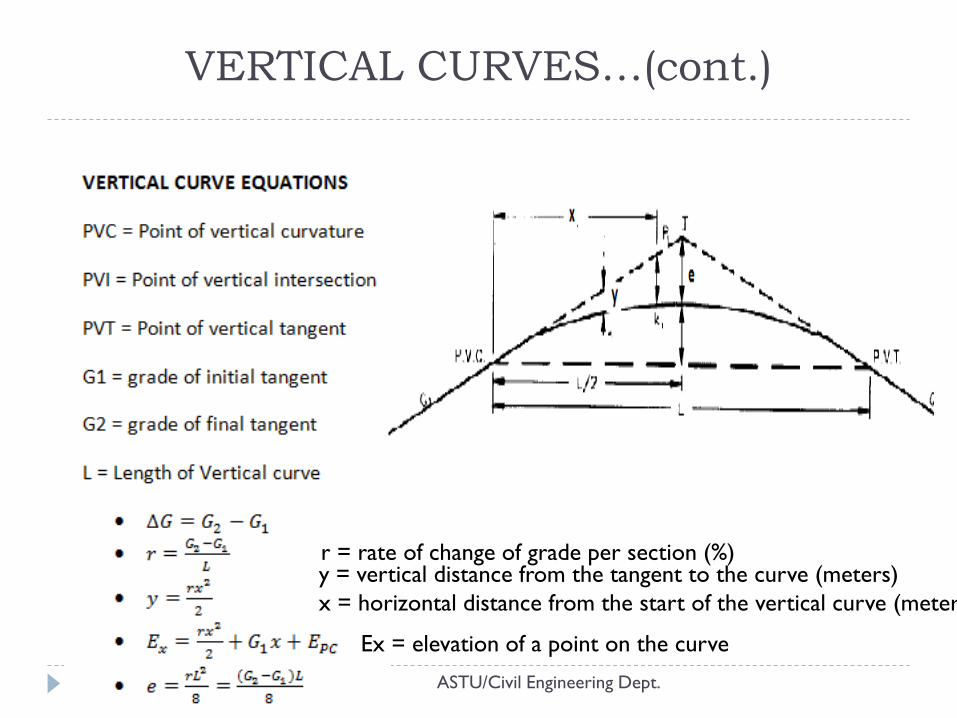
VERTICAL CURVES…(cont.)
71
y = vertical distance from the tangent to the curve (meters)
x = horizontal distance from the start of the vertical curve (meters)
r = rate of change of grade per section (%)
Ex = elevation of a point on the curve
ASTU/Civil Engineering Dept.
GRADES
ASTU/Civil Engineering Dept. 72
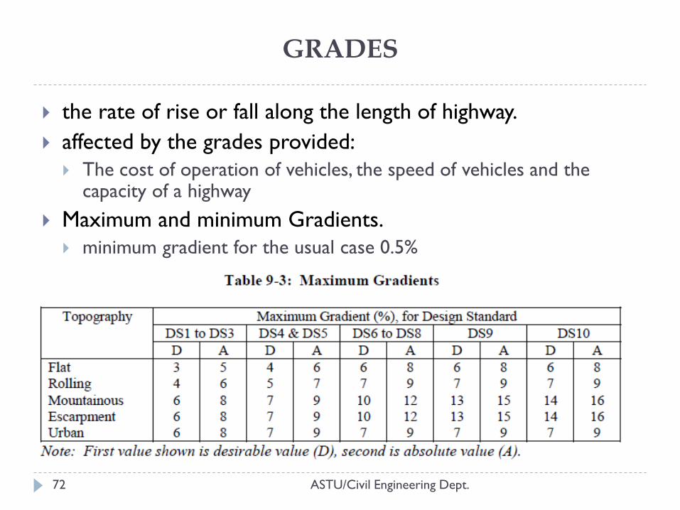
the rate of rise or fall along the length of highway.
affected by the grades provided:
The cost of operation of vehicles, the speed of vehicles and the capacity of a highway
Maximum and minimum Gradients.
minimum gradient for the usual case 0.5%
Length of Crest Vertical Curves
ASTU/Civil Engineering Dept. 73
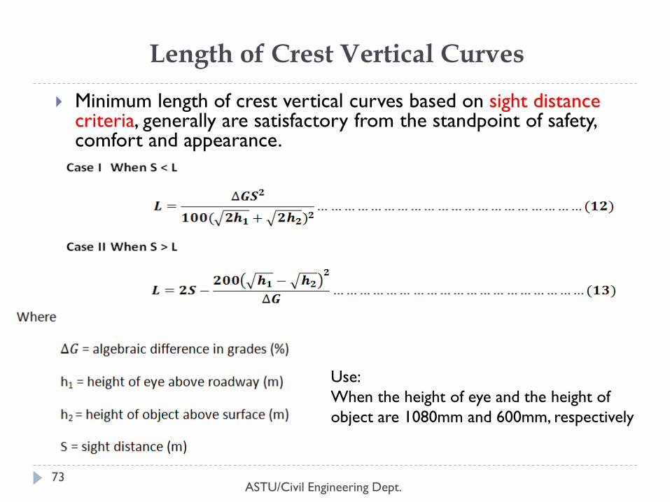
Minimum length of crest vertical curves based on sight distance criteria, generally are satisfactory from the standpoint of safety, comfort and appearance.
Use:
When the height of eye and the height of
object are 1080mm and 600mm, respectively
Length of Crest Vertical Curves…(cont.)
ASTU/Civil Engineering Dept. 74
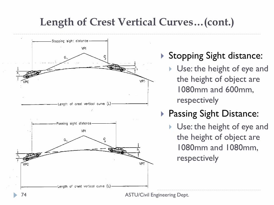
Stopping Sight distance:
Use: the height of eye and
the height of object are
1080mm and 600mm,
respectively
Passing Sight Distance:
Use: the height of eye and
the height of object are
1080mm and 1080mm,
respectively
Length of Sag Vertical Curves
ASTU/Civil Engineering Dept. 75
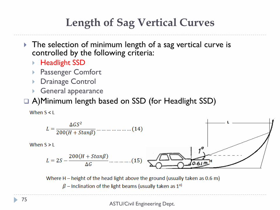
The selection of minimum length of a sag vertical curve is controlled by the following criteria: Headlight SSD
Passenger Comfort
Drainage Control
General appearance
A)Minimum length based on SSD (for Headlight SSD)
Length of Sag Vertical Curves..(cont.)
ASTU/Civil Engineering Dept. 76
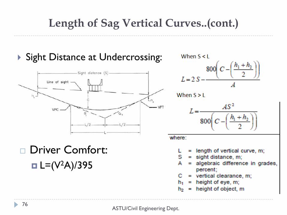
Sight Distance at Undercrossing:
Driver Comfort:
L=(V2A)/395
Length of Crest and Sag Vertical Curves Based on K factors
77
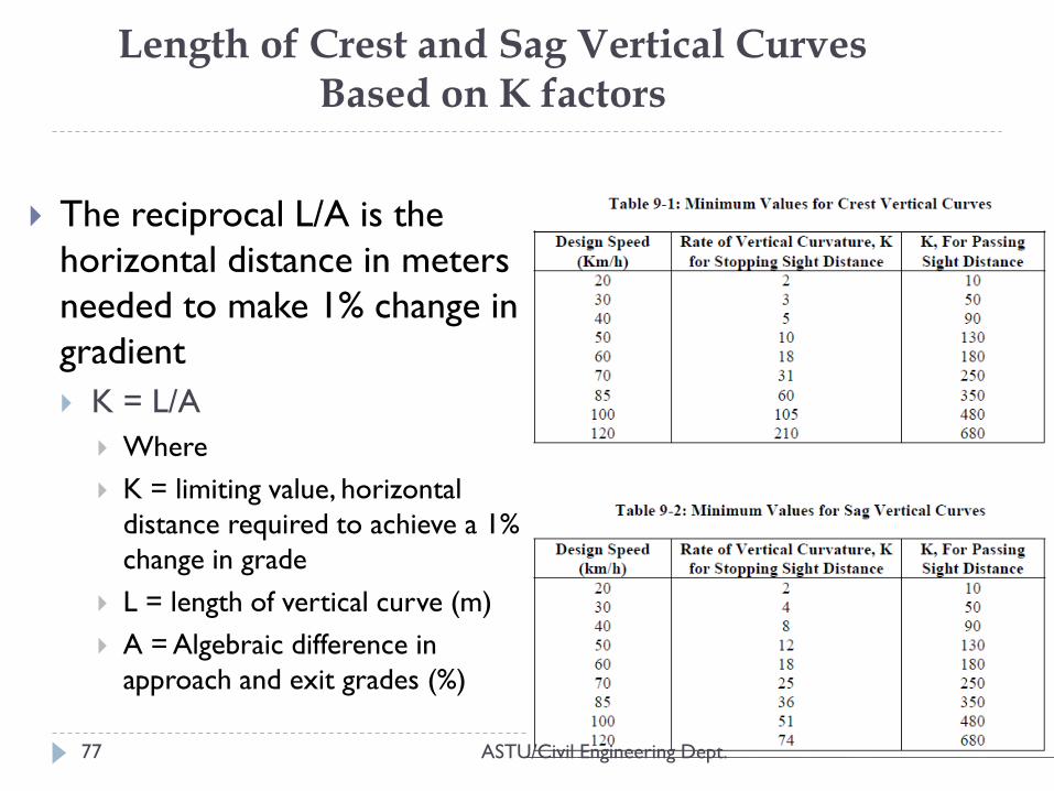
The reciprocal L/A is the
horizontal distance in meters
needed to make 1% change in
gradient
K = L/A
Where
K = limiting value, horizontal
distance required to achieve a 1%
change in grade
L = length of vertical curve (m)
A = Algebraic difference in
approach and exit grades (%)
ASTU/Civil Engineering Dept.
Vertical Alignment Considerations
ASTU/Civil Engineering Dept. 78
Vertical Alignment Considerations:
The profile should be smooth with gradual changes consistent
with the type of facility and the character of the surrounding
terrain.
A ―roller-coaster‖ or ―hidden dip‖ profile should be avoided.
Undulating grade lines involving substantial lengths of steeper
grades should be appraised for their effect on traffic operation,
since they may encourage excessive truck speeds.
Broken-back grade lines (two vertical curves—a pair of either
crest curves or sag curves—separated by a short tangent grade)
should generally be avoided.
7. PHASING OF HORIZONTAL AND VERTICAL ALIGNMENTS
ASTU/Civil Engineering Dept. 79
implies their coordination so that the line of the road appears to a driver to flow smoothly, avoiding the creation of hazards and visual defects.
horizontal curves will be longer than vertical curves.
It is generally more pleasing to the driver when vertical curvature can be superimposed on horizontal curvature.
Sharp horizontal curves should not be introduced at or near the top of a pronounced crest vertical curve or at or near the low point of a pronounced sag vertical curve.
On two-lane roadways, long tangent sections (horizontal and vertical) are desirable to provide adequate passing sections.
Horizontal and vertical curves should be as flat as possible at intersections where sight distances along both roads and streets is important and vehicles may have to slow or stop.
THANK YOU
ASTU/Civil Engineering Dept. 80
QUESTIONS?
Highway Engineering-I
Chapter Four:
EARTHWORK QUANTITIES AND MASS HAUL DIAGRAM
ASTU/Civil Engineering Dept. 1
Instructor: Fasika Mekonnen
1. INTRODUCTION
ASTU/Civil Engineering Dept. 2
Earthworks of highways include:
Earthwork activities.
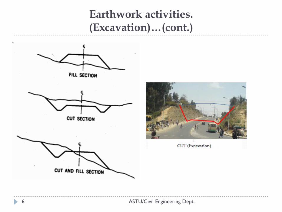
Excavation(cut & fill)
Earthwork quantities and calculations.
Area of cross sections.
Determination of volume of earthworks by appropriate methods.
The mass‐haul diagram.
Determination of the planned movement of materials.
Calculation of the mean haul distance and the corresponding cost.
Earthwork activities. (Excavation)
3
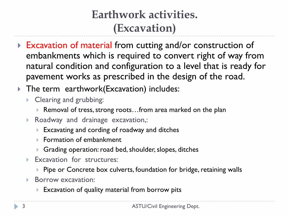
Excavation of material from cutting and/or construction of embankments which is required to convert right of way from natural condition and configuration to a level that is ready for pavement works as prescribed in the design of the road.
The term earthwork(Excavation) includes:
Clearing and grubbing:
Removal of tress, strong roots…from area marked on the plan
Roadway and drainage excavation,:
Excavating and cording of roadway and ditches
Formation of embankment
Grading operation: road bed, shoulder, slopes, ditches
Excavation for structures:
Pipe or Concrete box culverts, foundation for bridge, retaining walls
Borrow excavation:
Excavation of quality material from borrow pits
ASTU/Civil Engineering Dept.
ASTU/Civil Engineering Dept. 4
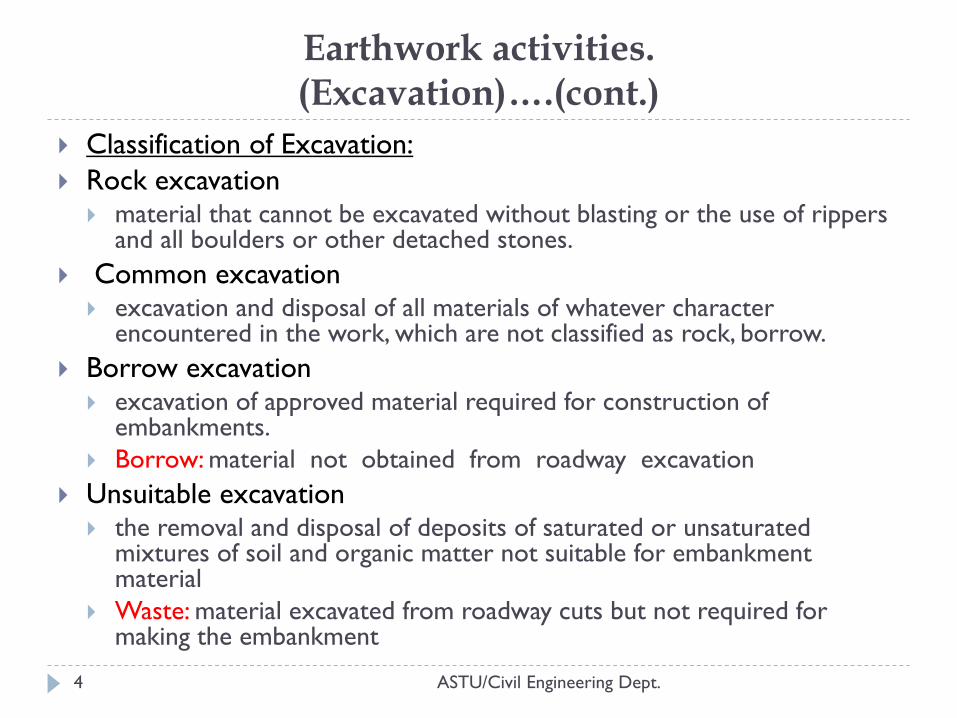
Classification of Excavation:
Rock excavation material that cannot be excavated without blasting or the use of rippers
and all boulders or other detached stones.
Common excavation excavation and disposal of all materials of whatever character
encountered in the work, which are not classified as rock, borrow.
Borrow excavation excavation of approved material required for construction of
embankments.
Borrow: material not obtained from roadway excavation
Unsuitable excavation the removal and disposal of deposits of saturated or unsaturated
mixtures of soil and organic matter not suitable for embankment material
Waste: material excavated from roadway cuts but not required for making the embankment
Earthwork activities. (Excavation)….(cont.)
Earthwork activities. (Excavation) …(cont.)
ASTU/Civil Engineering Dept. 5
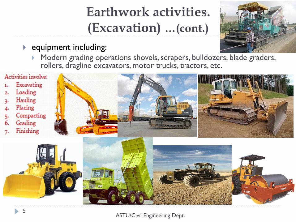
equipment including: Modern grading operations shovels, scrapers, bulldozers, blade graders,
rollers, dragline excavators, motor trucks, tractors, etc.
Earthwork activities. (Excavation)…(cont.)
ASTU/Civil Engineering Dept. 6
2. Earthwork Quantities
ASTU/Civil Engineering Dept. 7
Area of Cross-Section:
(1) the graphical method and
(2) the coordinate method
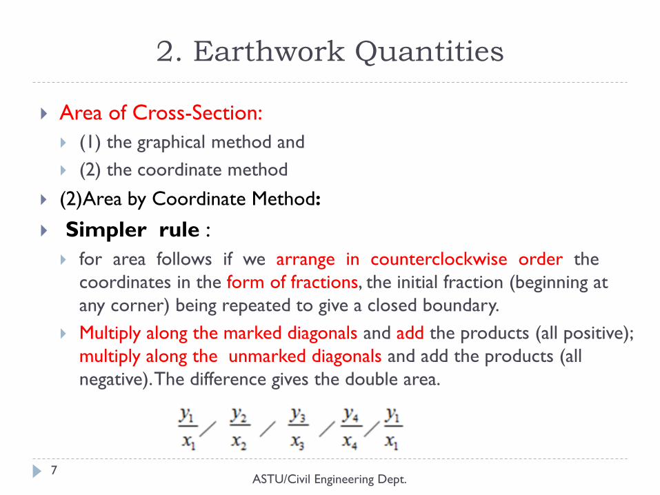
(2)Area by Coordinate Method:
Simpler rule :
for area follows if we arrange in counterclockwise order the
coordinates in the form of fractions, the initial fraction (beginning at
any corner) being repeated to give a closed boundary.
Multiply along the marked diagonals and add the products (all positive);
multiply along the unmarked diagonals and add the products (all
negative). The difference gives the double area.
Earthwork Quantities…(cont.)
ASTU/Civil Engineering Dept. 8
Trapezoidal Rule:
A trapezoidal rule assumes that if the interval b/n offset is
small, the boundary can be approximated to a straight line b/n
the offset.
A=L/2(O1+On+2(O2+O3+…..+On-1)
Simpson Rule:
This method assumes that instead of being made up of a series
of straight lines the boundary consists of a series of parabolic
area.
A=L/3(O1+On+4(∑even offset) +2(∑odd offset))
Earthwork Quantities…(cont.)
ASTU/Civil Engineering Dept. 9
Volume of Earthwork The volume of earthwork may be found by means:
average end area
prismoidal formula.
Average End Area Formula Volume = V = ½ (A1 + A2)L
In which: A1 and A2 = area of end sections (m2)
L = length of solid(m)
This formula is applied to areas of any shape, but the results are slightly too large. The error is small if the sections do not change rapidly.
Prismoidal Formula. V = L/6 (A1 + 4Am + A2)
In which L is the distance between the two parallel bases A1 and A2 and Am is a section midway between the two end bases and parallel to them. Am is not an average of A1 and A2, but each of its linear dimensions is an average of the corresponding dimensions of A1 and A2.
SHRINKAGE AND SWELL
ASTU/Civil Engineering Dept. 10
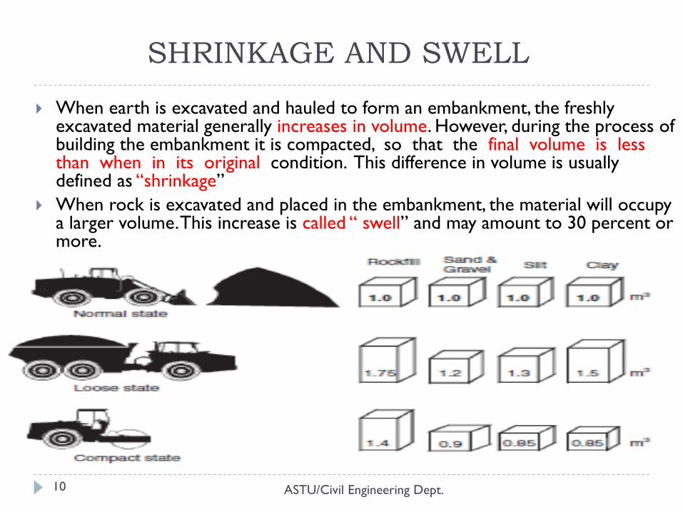
When earth is excavated and hauled to form an embankment, the freshly excavated material generally increases in volume. However, during the process of building the embankment it is compacted, so that the final volume is less than when in its original condition. This difference in volume is usually defined as “shrinkage”
When rock is excavated and placed in the embankment, the material will occupy a larger volume. This increase is called “ swell” and may amount to 30 percent or more.
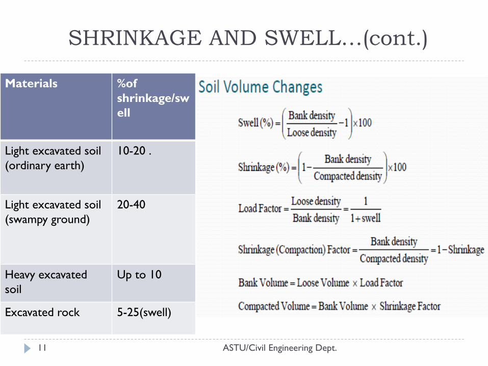
SHRINKAGE AND SWELL…(cont.)
ASTU/Civil Engineering Dept. 11
Materials %of
shrinkage/sw
ell
Light excavated soil
(ordinary earth)
10-20 .
Light excavated soil
(swampy ground)
20-40
Heavy excavated
soil
Up to 10
Excavated rock 5-25(swell)
3. MASS HAUL DIAGRAM
ASTU/Civil Engineering Dept. 12
a curve in which the abscissas represent the stations of the survey and the ordinates represent the algebraic sum of excavation and embankment quantities from some point of beginning on the profile.
The steps involves:
End area calculations
Earthwork calculations
Preparation of mass haul diagram
Balancing earthworks using the mass haul diagram
A final stage of geometric design is then usually to make adjustments to the alignments in the interests of balancing or minimizing the earthwork quantities.
MASS HAUL DIAGRAM…(cont.)
ASTU/Civil Engineering Dept. 13
Mass‐Haul Diagrams
A Mass Haul Diagram is a continuous curve representing the cumulative volume of earthwork along the linear profile of a roadway or airfield
Mass diagrams are extremely useful in determining the most economical distribution of material
Horizontal stationing is plotted along the x‐axis
Net earthwork values are plotted along the y‐axis
cumulative earthwork from the origin to that Point
upward sloping curves (rising left to right) indicate a cut
downward sloping curves (falling left to right) occur in a fill section
peaks indicate a change from cut to fill and
valleys occur when the earthwork changes from fill to cut
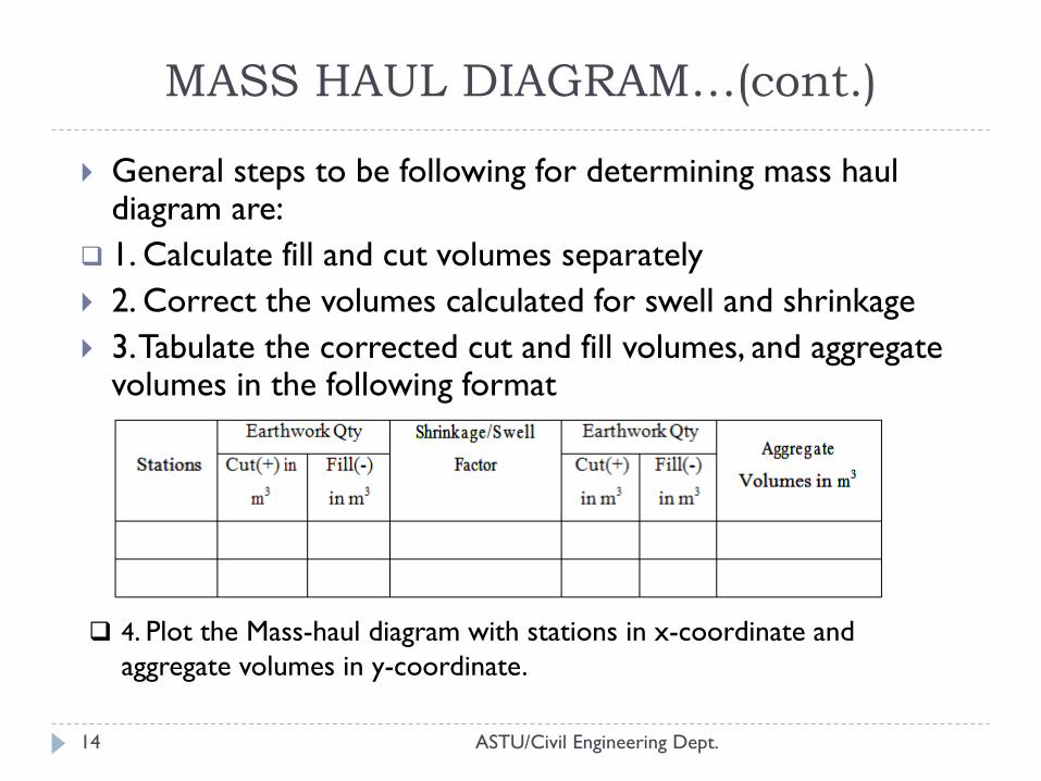
MASS HAUL DIAGRAM…(cont.)
ASTU/Civil Engineering Dept. 14
General steps to be following for determining mass haul diagram are:
1. Calculate fill and cut volumes separately
2. Correct the volumes calculated for swell and shrinkage
3. Tabulate the corrected cut and fill volumes, and aggregate volumes in the following format
4. Plot the Mass-haul diagram with stations in x-coordinate and
aggregate volumes in y-coordinate.
MASS HAUL DIAGRAM…(cont.)
ASTU/Civil Engineering Dept. 15
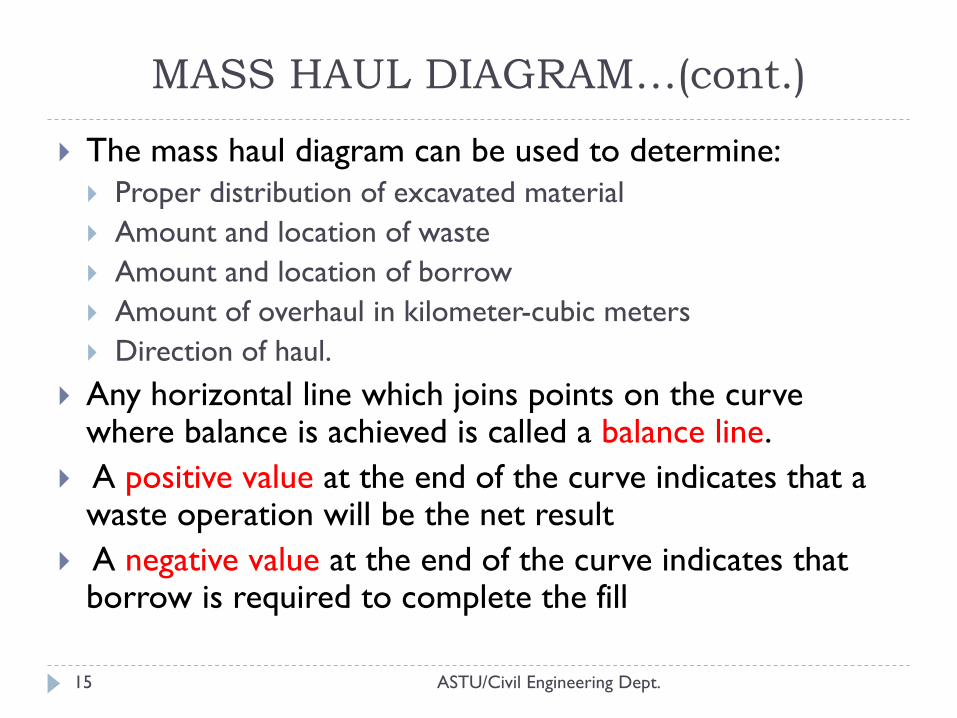
The mass haul diagram can be used to determine:
Proper distribution of excavated material
Amount and location of waste
Amount and location of borrow
Amount of overhaul in kilometer-cubic meters
Direction of haul.
Any horizontal line which joins points on the curve where balance is achieved is called a balance line.
A positive value at the end of the curve indicates that a waste operation will be the net result
A negative value at the end of the curve indicates that borrow is required to complete the fill
MASS HAUL DIAGRAM…(cont.)
ASTU/Civil Engineering Dept. 16
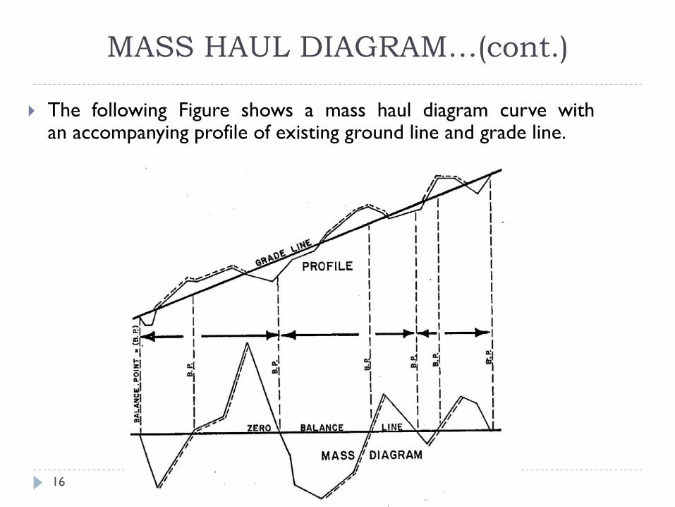
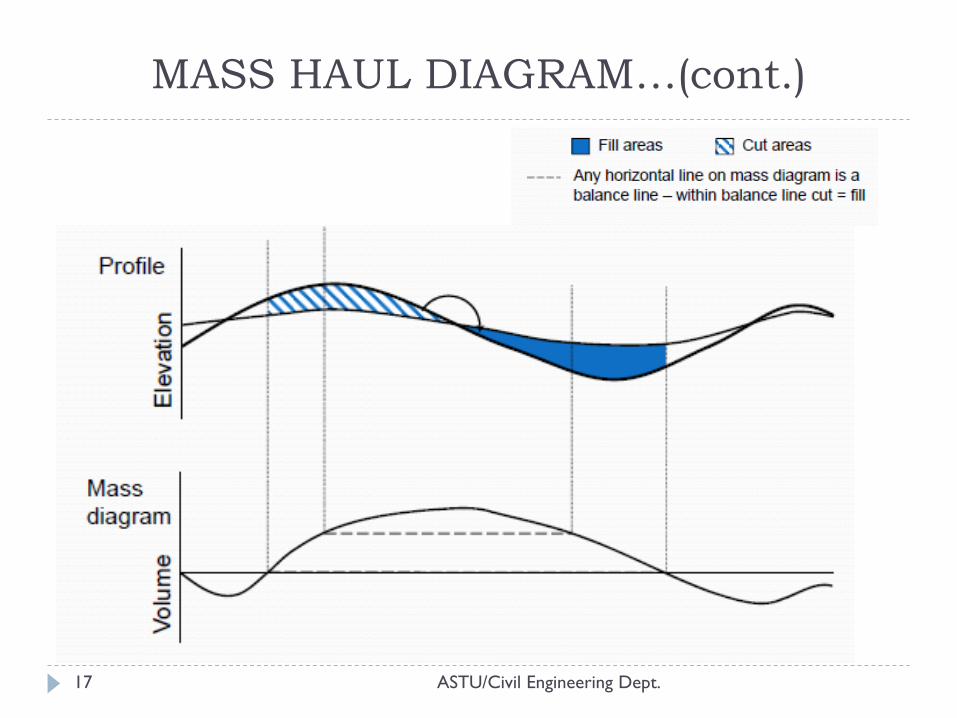
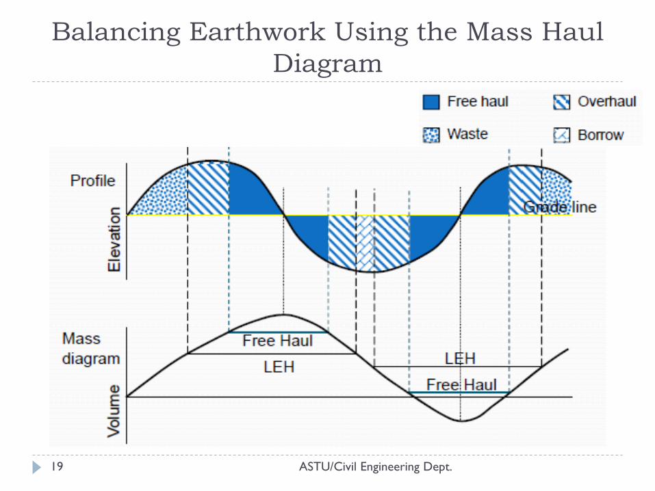
The following Figure shows a mass haul diagram curve with an accompanying profile of existing ground line and grade line.
MASS HAUL DIAGRAM…(cont.)
ASTU/Civil Engineering Dept. 17
ASTU/Civil Engineering Dept. 18
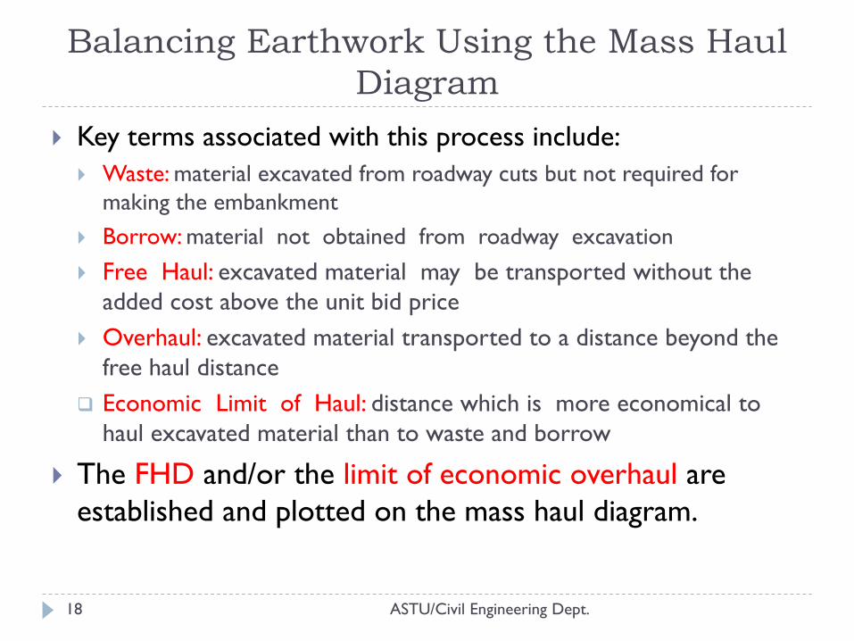
Key terms associated with this process include:
Waste: material excavated from roadway cuts but not required for
making the embankment
Borrow: material not obtained from roadway excavation
Free Haul: excavated material may be transported without the
added cost above the unit bid price
Overhaul: excavated material transported to a distance beyond the
free haul distance
Economic Limit of Haul: distance which is more economical to
haul excavated material than to waste and borrow
The FHD and/or the limit of economic overhaul are
established and plotted on the mass haul diagram.
Balancing Earthwork Using the Mass Haul
Diagram
Balancing Earthwork Using the Mass Haul
Diagram
ASTU/Civil Engineering Dept. 19
ECONOMICAL ANALYSIS
ASTU/Civil Engineering Dept. 20
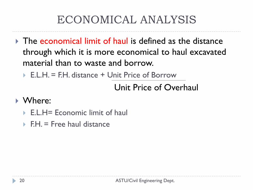
The economical limit of haul is defined as the distance
through which it is more economical to haul excavated
material than to waste and borrow.
E.L.H. = F.H. distance + Unit Price of Borrow
Unit Price of Overhaul
Where:
E.L.H= Economic limit of haul
F.H. = Free haul distance
USE OF MASS HAUL DIAGRAM
ASTU/Civil Engineering Dept. 21
If mass curve is drawn for each trial grade it can be used
for selecting the most economical gradient which balance
the cut & fill.
Once the formation level is designed, it can be used to
indicate the most economical method of moving the earth
around the project and a good estimate of overall cost of
the earth work can be calculated.
The required volumes of material are known before
construction begins enabling suitable plant and machinery
to be chosen, site for spoil- hups and borrow pits to be
located and direction of haul to be established.
THANK YOU
ASTU/Civil Engineering Dept. 22
QUESTIONS?
Highway Engineering-I
Chapter Five:
INTERSECTION AND TERMINALS
ASTU/Civil Engineering Dept.
Instructor: Fasika Mekonnen
1
INTRODUCTION
ASTU/Civil Engineering Dept. 2
An intersection is area where two or more highways join
or cross including the roadway and roadside facilities for
traffic movements within the area.
The efficiency, safety, speed, cost of operation, and capacity of
road infrastructures depend on the design of intersections.
A highway intersection is required to control conflicting and
merging streams of traffic so that delay is minimized.
This is achieved through choice of geometric parameters that
control and regulate the vehicle paths through the intersection.
Intersections vary in complexity from a simple intersection
ASTU/Civil Engineering Dept. 3
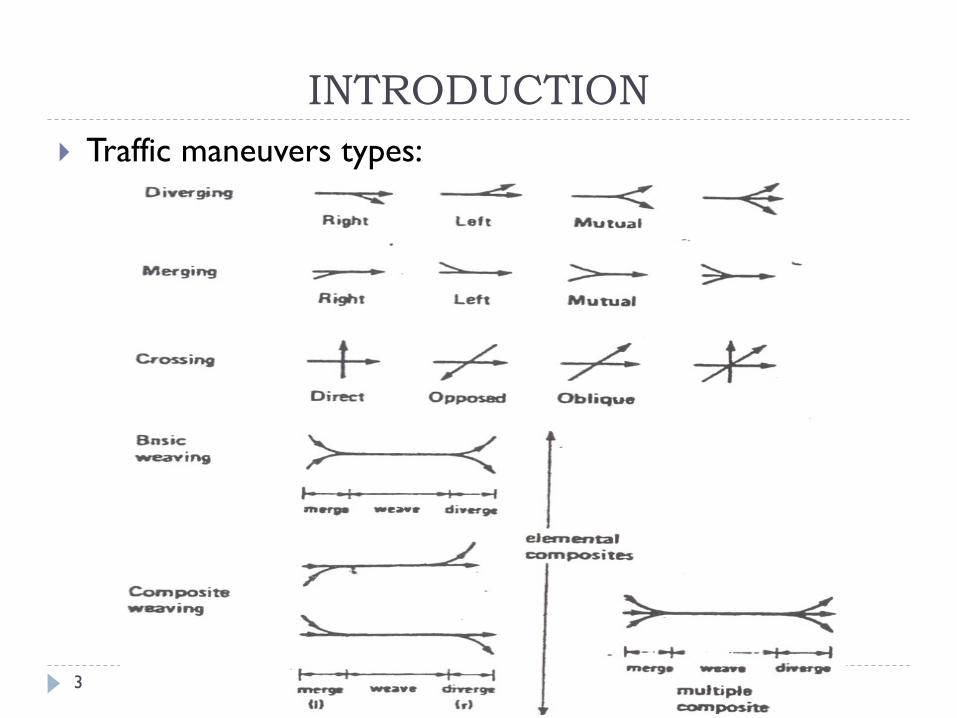
Traffic maneuvers types:
INTRODUCTION
ASTU/Civil Engineering Dept. 4
Basic elements that should be considered in the design of
intersections are:
Human factors, Physical elements and Environmental factors
Human factors
Driving habit
Ability of driver to make decision
Driver expectancy
Decision and reaction time
Conformance to natural paths of movement
Pedestrian use and habit
Bicycle traffic use and habit
INTRODUCTION
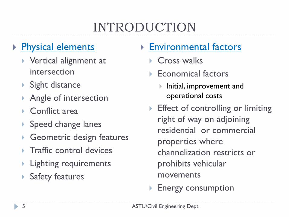
ASTU/Civil Engineering Dept. 5
Physical elements
Vertical alignment at
intersection
Sight distance
Angle of intersection
Conflict area
Speed change lanes
Geometric design features
Traffic control devices
Lighting requirements
Safety features
Environmental factors
Cross walks
Economical factors
Initial, improvement and
operational costs
Effect of controlling or limiting
right of way on adjoining
residential or commercial
properties where
channelization restricts or
prohibits vehicular
movements
Energy consumption
INTRODUCTION
ASTU/Civil Engineering Dept. 6
Intersections are generally classified into three general
categories:
At- grade intersections,
Grade-separated without ramps, and
Grade-separated with ramps (interchanges)
Selection of Junction Type
The choice of a intersection type requires knowledge of
traffic demand,
intersection performance and
accident prediction.
INTRODUCTION
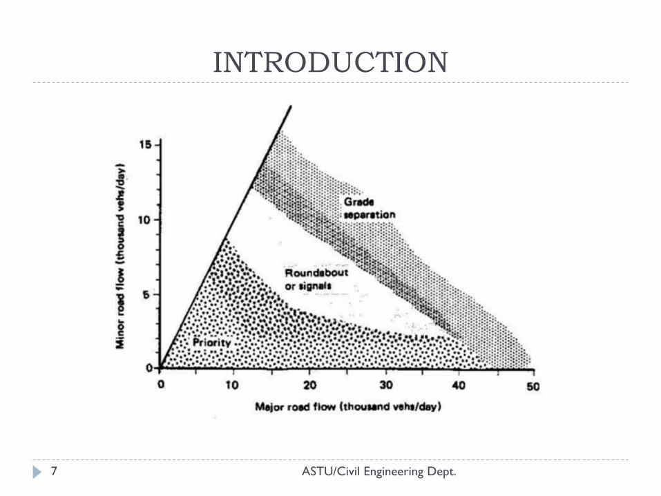
ASTU/Civil Engineering Dept. 7
INTRODUCTION
ASTU/Civil Engineering Dept. 8
Basic advantages and disadvantages of different junction types, including grade separation, are as follows:
Priority (T-Junction, Cross-Junction).
For low flows: Can cause long delays.
Delays can be improved by signal installation.
Requires sufficient stopping sight distance.
Roundabouts.
For low to medium flows: Minimal delays at lower flows.
Shown to be safer than priority junctions.
Requires attention to pedestrian movements and accommodation of slow-moving traffic.
Grade-Separation.
For high flows: Results in minimal delays.
Expensive.
INTRODUCTION
ASTU/Civil Engineering Dept. 9
INTRODUCTION
ASTU/Civil Engineering Dept. 10
INTRODUCTION
At Grade Intersections
ASTU/Civil Engineering Dept. 11
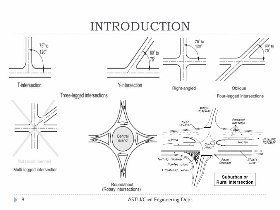
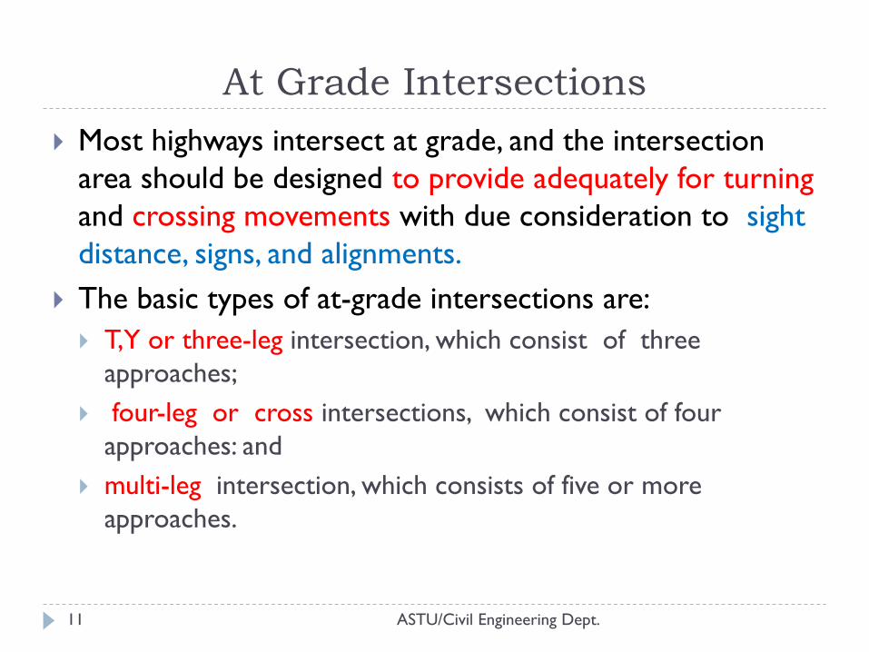
Most highways intersect at grade, and the intersection
area should be designed to provide adequately for turning
and crossing movements with due consideration to sight
distance, signs, and alignments.
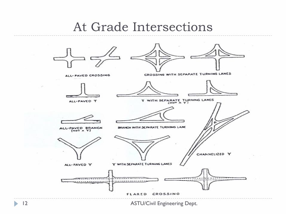
The basic types of at-grade intersections are:
T,Y or three-leg intersection, which consist of three
approaches;
four-leg or cross intersections, which consist of four
approaches: and
multi-leg intersection, which consists of five or more
approaches.
ASTU/Civil Engineering Dept. 12
At Grade Intersections
Grade separations and Interchanges
ASTU/Civil Engineering Dept. 13
Intersection at grade can be eliminated by the use of
grade-separation structures that permit the cross flow of
traffic at different levels without interruption.
The advantage of such separation is the freedom from cross
interference with resultant saving of time and increase in safety
for traffic movements.
An interchange is a grade separation in which vehicles
moving in one direction of flow may transfer by the use
of connecting roadways.
These connecting roadways at interchanges are called ramps.
ASTU/Civil Engineering Dept. 14
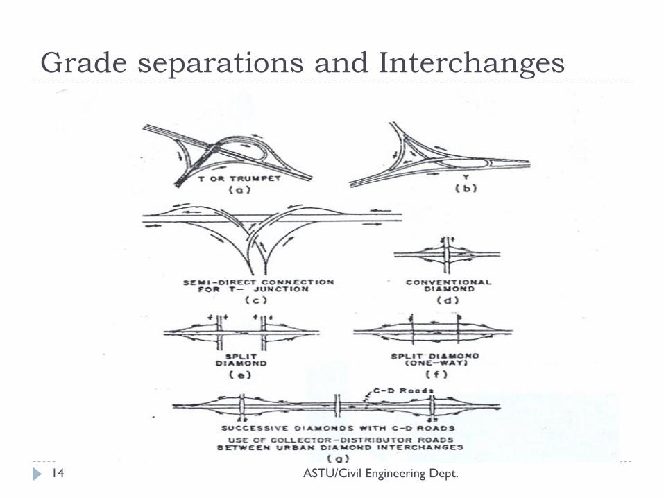
Grade separations and Interchanges
ASTU/Civil Engineering Dept. 15
Grade separations and Interchanges
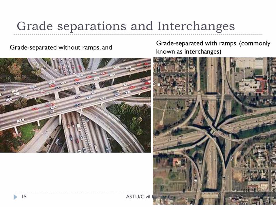
Grade-separated without ramps, and Grade-separated with ramps (commonly
known as interchanges)
ASTU/Civil Engineering Dept. 16
Grade separations and interchanges may be warranted: As part of an express highway system designed to carry high volumes of traffic,
To eliminate bottlenecks,
To prevent accidents,
Where the topography is such that other types of design are not feasible,
Where the volumes to be catered for would require the design of an intersection at grade of unreasonable size, and
Where the road user benefit of reducing delays at an at- grade intersection exceeds the cost of the improvement.
The choice between these intersection types depends on: traffic,
economy,
safety,
aesthetics,
delay,
space requirements, etc.
Grade separations and Interchanges
Design Principles of At-Grade Intersections
ASTU/Civil Engineering Dept. 17
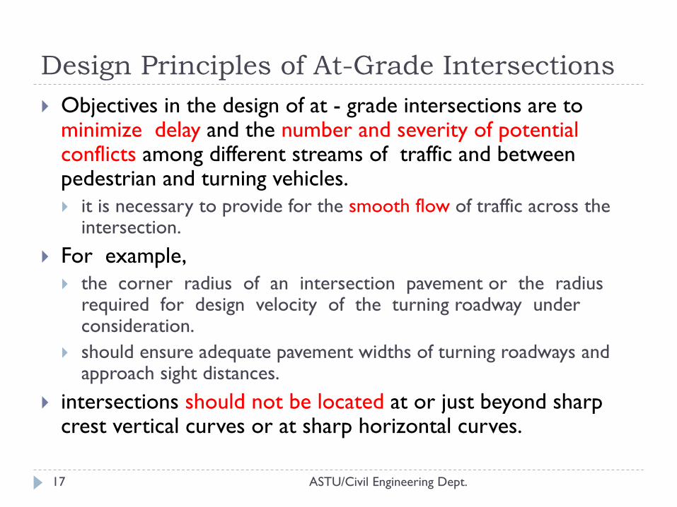
Objectives in the design of at - grade intersections are to minimize delay and the number and severity of potential conflicts among different streams of traffic and between pedestrian and turning vehicles.
it is necessary to provide for the smooth flow of traffic across the intersection.
For example,
the corner radius of an intersection pavement or the radius required for design velocity of the turning roadway under consideration.
should ensure adequate pavement widths of turning roadways and approach sight distances.
intersections should not be located at or just beyond sharp crest vertical curves or at sharp horizontal curves.
ASTU/Civil Engineering Dept. 18
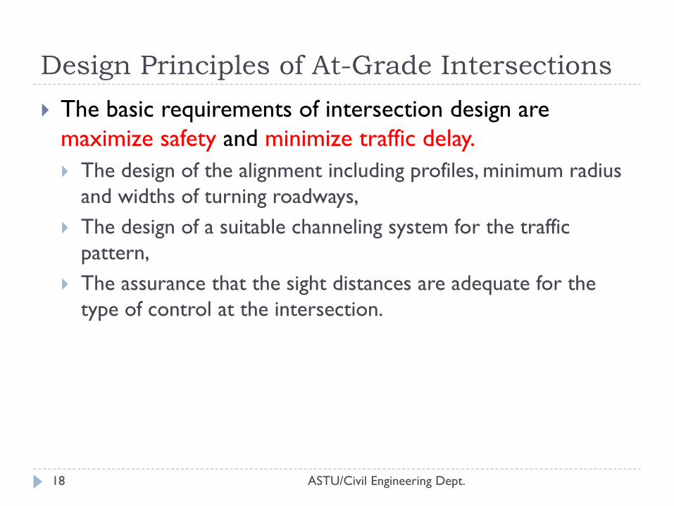
The basic requirements of intersection design are
maximize safety and minimize traffic delay.
The design of the alignment including profiles, minimum radius
and widths of turning roadways,
The design of a suitable channeling system for the traffic
pattern,
The assurance that the sight distances are adequate for the
type of control at the intersection.
Design Principles of At-Grade Intersections
ASTU/Civil Engineering Dept. 19
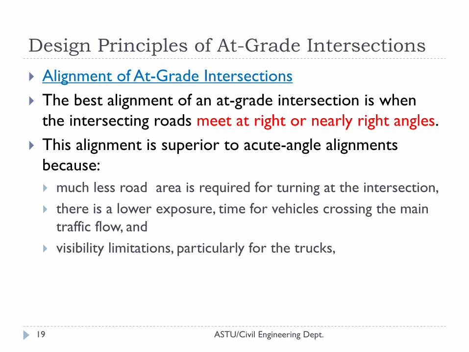
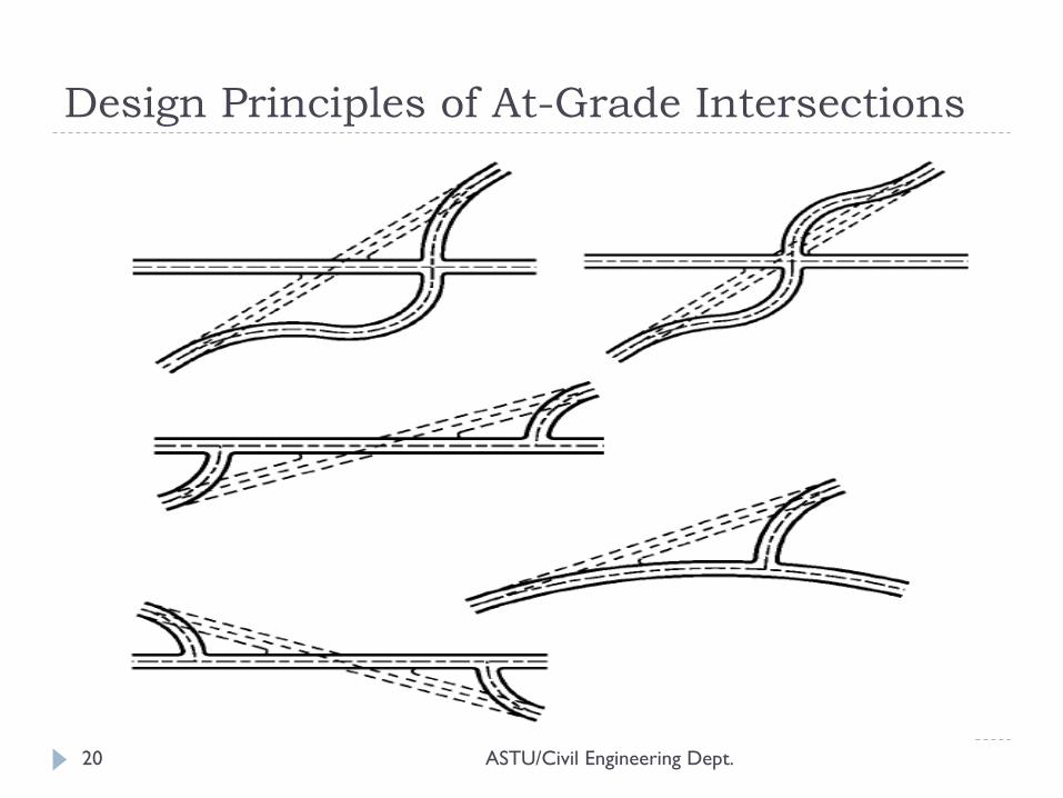
Alignment of At-Grade Intersections
The best alignment of an at-grade intersection is when
the intersecting roads meet at right or nearly right angles.
This alignment is superior to acute-angle alignments
because:
much less road area is required for turning at the intersection,
there is a lower exposure, time for vehicles crossing the main
traffic flow, and
visibility limitations, particularly for the trucks,
Design Principles of At-Grade Intersections
ASTU/Civil Engineering Dept. 20
Design Principles of At-Grade Intersections
ASTU/Civil Engineering Dept. 21
In designing the profile (vertical alignment) at the
intersection large changes in grade should be avoided;
preferably, grades should not be greater than 3 percent.
In any case, it is not advisable to use grades higher than 6
percent at intersections.
main factors governing the design of curves at at-angle
intersections.
The angle of turn,
the turning speed,
the design vehicle, and
traffic volume
Design Principles of At-Grade Intersections
ASTU/Civil Engineering Dept. 22
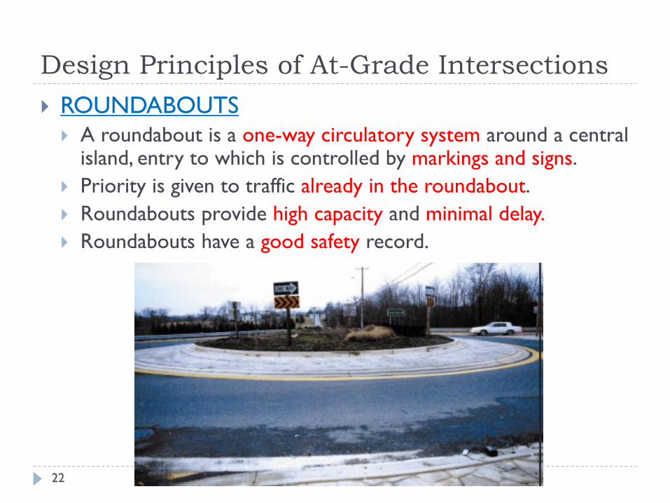
ROUNDABOUTS
A roundabout is a one-way circulatory system around a central island, entry to which is controlled by markings and signs.
Priority is given to traffic already in the roundabout.
Roundabouts provide high capacity and minimal delay.
Roundabouts have a good safety record.
Design Principles of At-Grade Intersections
ASTU/Civil Engineering Dept. 23
Design Principles of At-Grade Intersections
ASTU/Civil Engineering Dept. 24
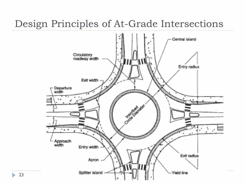
THE GENERAL LAYOUT
The general layout of a roundabout should provide for the following:
Adequate entry widths
Adequate circulation space compatible with entry widths
Central islands of diameter sufficient only to give drivers
guidance on the maneuvers expected.
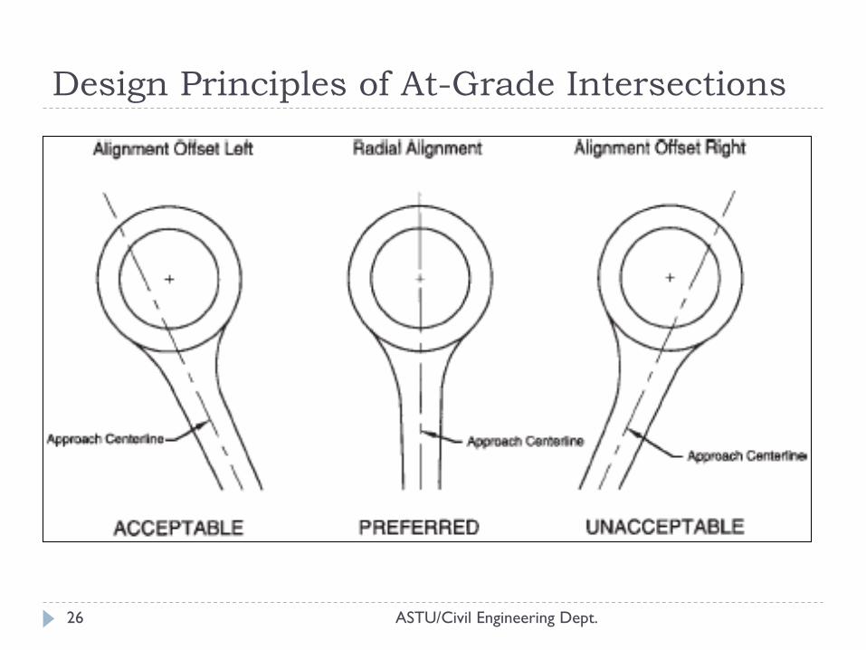
Deflection of the traffic to the right on entry to promote movement and ensure low traffic speeds.
A simple and clear layout
Suitable visibility at any entry of each adjacent entry
Entry and exit deflection angles and central island radius should be adjusted to the design speeds
Design Principles of At-Grade Intersections
ASTU/Civil Engineering Dept. 25
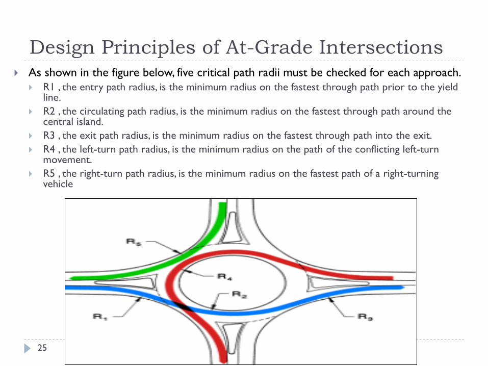
As shown in the figure below, five critical path radii must be checked for each approach.
R1 , the entry path radius, is the minimum radius on the fastest through path prior to the yield line.
R2 , the circulating path radius, is the minimum radius on the fastest through path around the central island.
R3 , the exit path radius, is the minimum radius on the fastest through path into the exit.
R4 , the left-turn path radius, is the minimum radius on the path of the conflicting left-turn movement.
R5 , the right-turn path radius, is the minimum radius on the fastest path of a right-turning vehicle
Design Principles of At-Grade Intersections
ASTU/Civil Engineering Dept. 26
Design Principles of At-Grade Intersections
ASTU/Civil Engineering Dept. 27
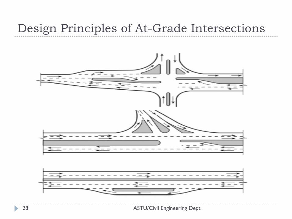
Channelistation of At-Grade Intersections
Channelization is the separation or regulation of conflicting traffic movements into definite paths of travel by traffic islands or pavement markings to facilitate the orderly movement of both vehicles and pedestrians. Proper channelization increases capacity, provides maximum convenience, and
instills driver confidence.
Channelization of intersections is considered for one or more of the following factors: Separation of conflicts
Control of angle of conflict
Reduction of excessive pavement areas
Regulation of traffic flow in the intersection area
Arrangements to favor a predominant turning movement protection of pedestrians
Protection of pedestrians
Protection and storage of turning and crossing vehicles
Location of traffic control devices
Design Principles of At-Grade Intersections
ASTU/Civil Engineering Dept. 28
Design Principles of At-Grade Intersections
ASTU/Civil Engineering Dept. 29
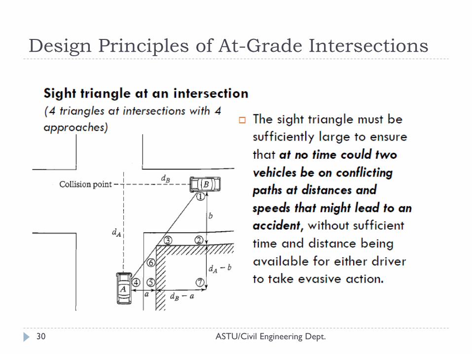
Sight distance at Intersections
Drivers on conflicting approaches must be able to see
other in time to assess whether an impeding hazard is
imposed and to take appropriate action to avoid an
accident.
Thus, sight distances must be analyzed to ensure that they
are sufficient for drivers to judge and avoid conflicts.
At-grade intersections either have:
no control
controlled by one of the following methods; yield control, stop
control, or signal control.
Design Principles of At-Grade Intersections
ASTU/Civil Engineering Dept. 30
Design Principles of At-Grade Intersections
ASTU/Civil Engineering Dept. 31
Design Principles of At-Grade Intersections
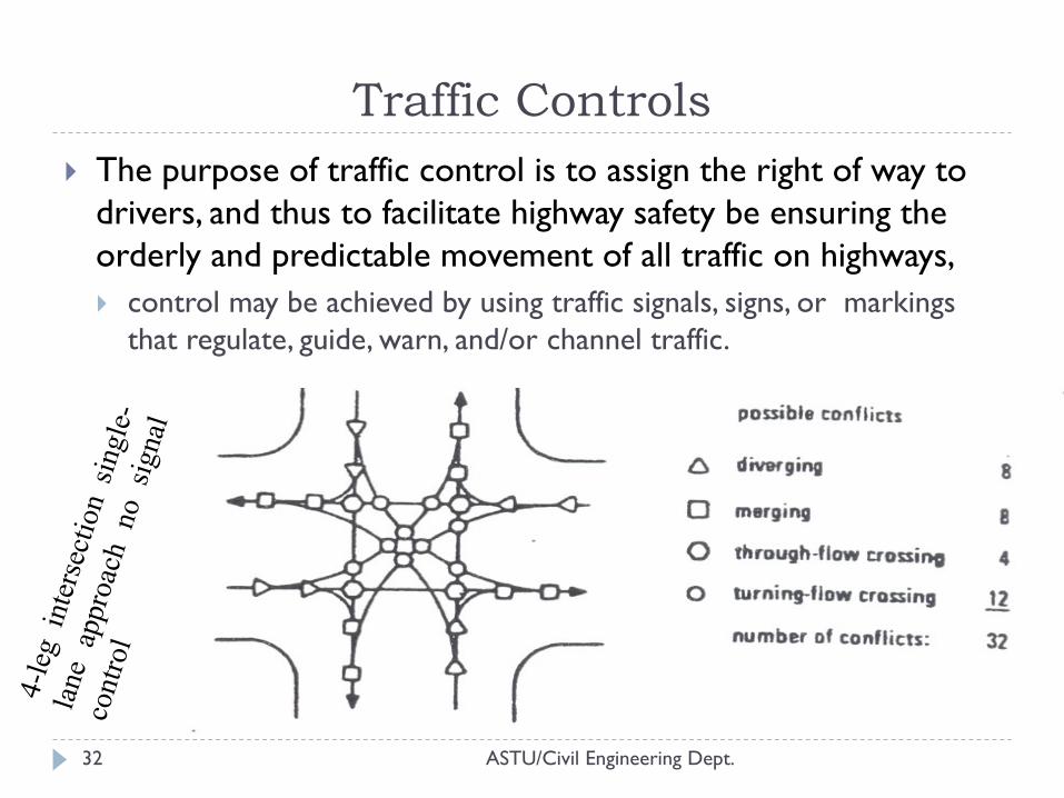
Traffic Controls
ASTU/Civil Engineering Dept. 32
The purpose of traffic control is to assign the right of way to
drivers, and thus to facilitate highway safety be ensuring the
orderly and predictable movement of all traffic on highways,
control may be achieved by using traffic signals, signs, or markings
that regulate, guide, warn, and/or channel traffic.
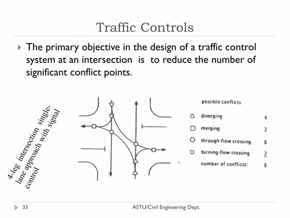
ASTU/Civil Engineering Dept. 33
The primary objective in the design of a traffic control
system at an intersection is to reduce the number of
significant conflict points.
Traffic Controls
ASTU/Civil Engineering Dept. 34
Types of intersection control
Several methods of controlling streams of vehicles at
intersections are in use.
The choice of on of these methods depends on:
the type of intersection and the volume of traffic in each of
the conflicting streams.
types of intersection control are described below:
YIELD signs
STOP signs
Roundabouts
Traffic signals
Traffic Controls
ASTU/Civil Engineering Dept. 35
YIELD signs: -
Yield signs are usually placed on minor road approaches; where it is necessary to yield the right of way to the major road traffic.
All drivers on approaches with yield signs are required to slow down and yield the right of way to all conflicting vehicles at the intersection.
Stopping at yield signs is not mandatory, but drivers are required to stop when necessary to avoid interfering with a traffic stream that has the right of way.
Traffic Controls
ASTU/Civil Engineering Dept. 36
STOP signs: -
A stop sign is used where an approaching vehicle is required to stop before entering the intersection.
A stop sign may be used on a minor road when it intersects a major road, at an un-signalized intersection, and where a combination of high speed, restricted view and serious accidents indicates the necessity for such a control.
Stop signs should not be used at signalized intersections or on through roadways of expressways.
Traffic Controls
ASTU/Civil Engineering Dept. 37
Roundabouts: -
A roundabout is a means of traffic control where one- way
traffic is circulating a round a central island priority with in the
roundabout is controlled by GIVEWAY(YIELD) signs for
entering traffic, although occasionally traffic signals may be
used.
It considerably reduces the number and severity of conflicts,
and makes the traffic flow self-regulatory and continuous,
reduces congestion, and promotes safety.
Traffic Controls
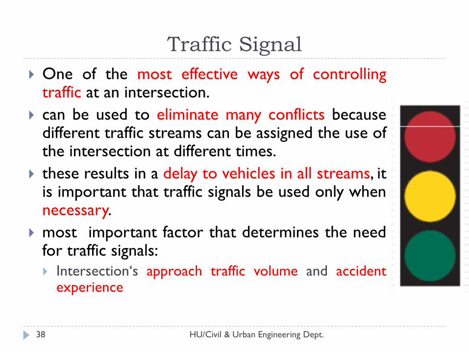
Traffic Signal
HU/Civil & Urban Engineering Dept. 38
One of the most effective ways of controlling traffic at an intersection.
can be used to eliminate many conflicts because different traffic streams can be assigned the use of the intersection at different times.
these results in a delay to vehicles in all streams, it is important that traffic signals be used only when necessary.
most important factor that determines the need for traffic signals:
Intersection‘s approach traffic volume and accident experience
HU/Civil & Urban Engineering Dept. 39
The efficient operation of the signal requires proper timing design
The cycle length for an isolated intersection should be short, preferably between 35 and 60sec.
For very high volumes, cycle lengths should be kept below 120sec…(excessive delay)
Advantage:
Provide orderly movement, Reduce delay, reduce accidents, Increase capacity
Disadvantage;
Maintenance & monitoring, inefficient during off peak times, increase rear end collisions, signal break down
Traffic Signal…cont.
HU/Civil & Urban Engineering Dept. 40
Type of traffic signals:
Fixed time signals:
Pre-timed signals are set to repeat regularly o cycle of red ,
yellow (amber) and green lights.
Vehicle actuated signals:
Signals in w/c the green periods vary and related to the actual
demands by traffic.
Semi-vehicle actuated signals:
The right of way rests with the main road and detectors are
located only on minor roads.
Traffic Signal…cont.
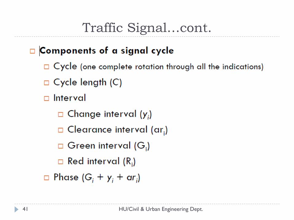
HU/Civil & Urban Engineering Dept. 41
Traffic Signal…cont.
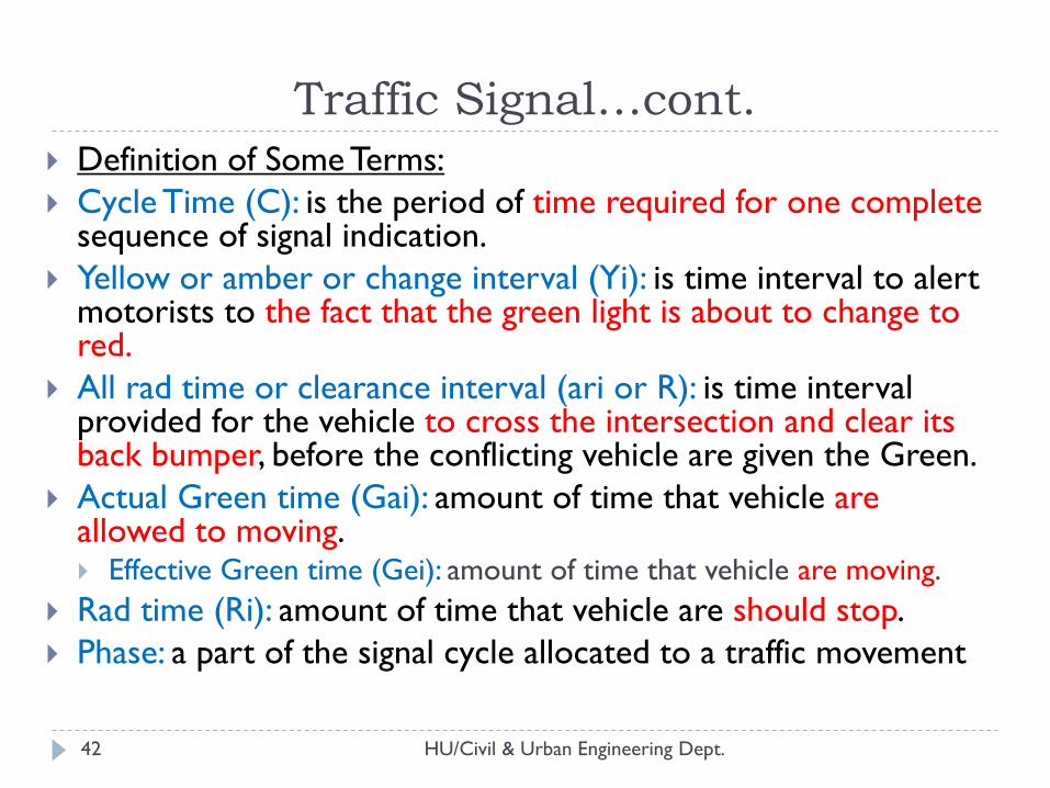
HU/Civil & Urban Engineering Dept. 42
Definition of Some Terms:
Cycle Time (C): is the period of time required for one complete sequence of signal indication.
Yellow or amber or change interval (Yi): is time interval to alert motorists to the fact that the green light is about to change to red.
All rad time or clearance interval (ari or R): is time interval provided for the vehicle to cross the intersection and clear its back bumper, before the conflicting vehicle are given the Green.
Actual Green time (Gai): amount of time that vehicle are allowed to moving. Effective Green time (Gei): amount of time that vehicle are moving.
Rad time (Ri): amount of time that vehicle are should stop.
Phase: a part of the signal cycle allocated to a traffic movement
Traffic Signal…cont.
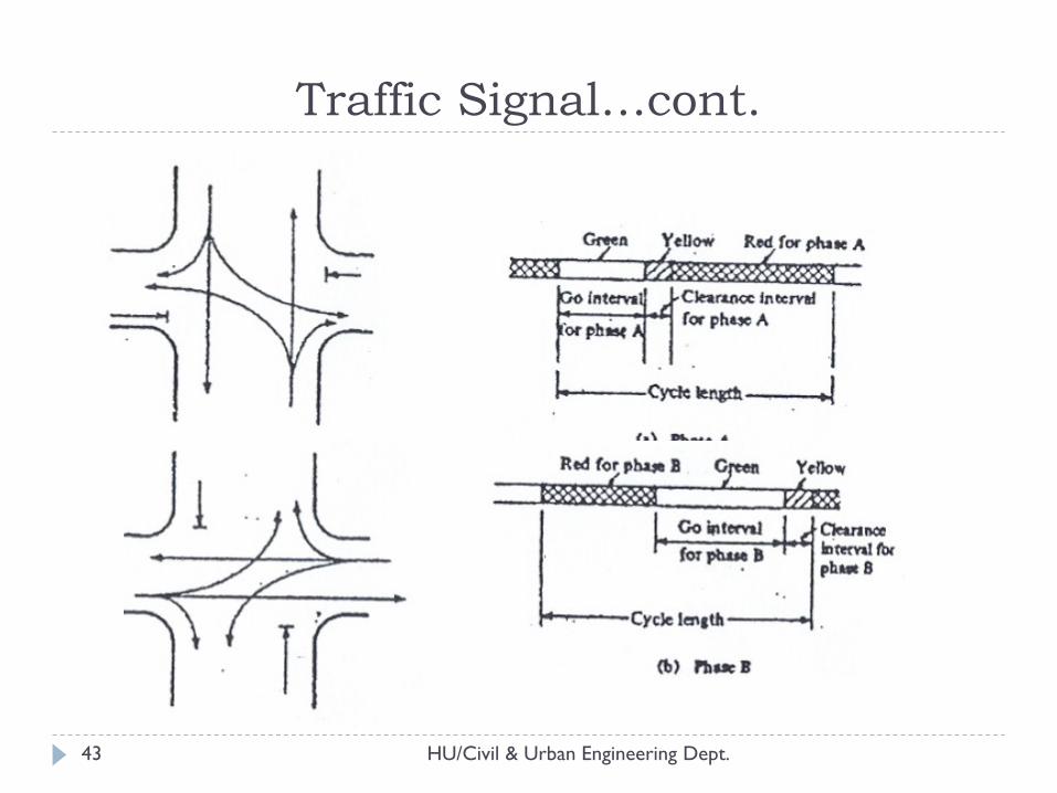
HU/Civil & Urban Engineering Dept. 43
Traffic Signal…cont.
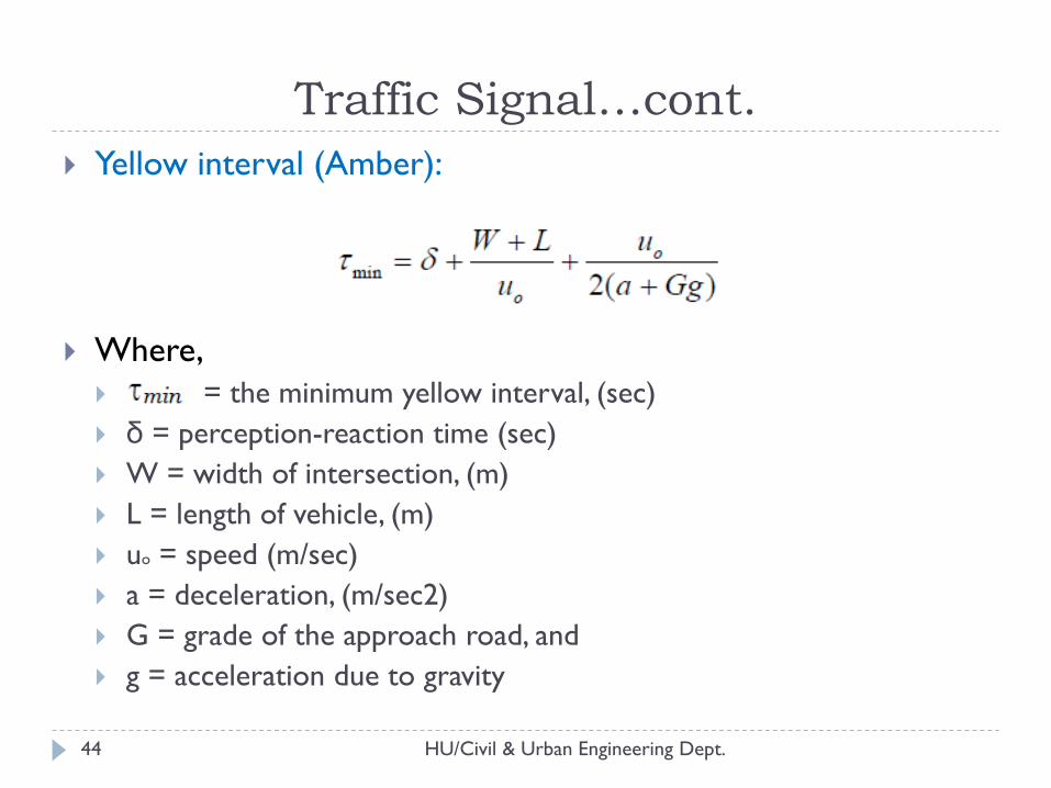
HU/Civil & Urban Engineering Dept. 44
Yellow interval (Amber):
Where,
= the minimum yellow interval, (sec)
δ = perception-reaction time (sec)
W = width of intersection, (m)
L = length of vehicle, (m)
uo = speed (m/sec)
a = deceleration, (m/sec2)
G = grade of the approach road, and
g = acceleration due to gravity
Traffic Signal…cont.
HU/Civil & Urban Engineering Dept. 45
Yellow intervals of 3 to 5 sec are normally used
When longer yellow intervals than 5 sec are computed
from the above equations,
an all-red phase can be inserted to follow the yellow indication,
but the change interval, yellow plus all-red, must be at least the
value computer from the equations.
Traffic Signal…cont.
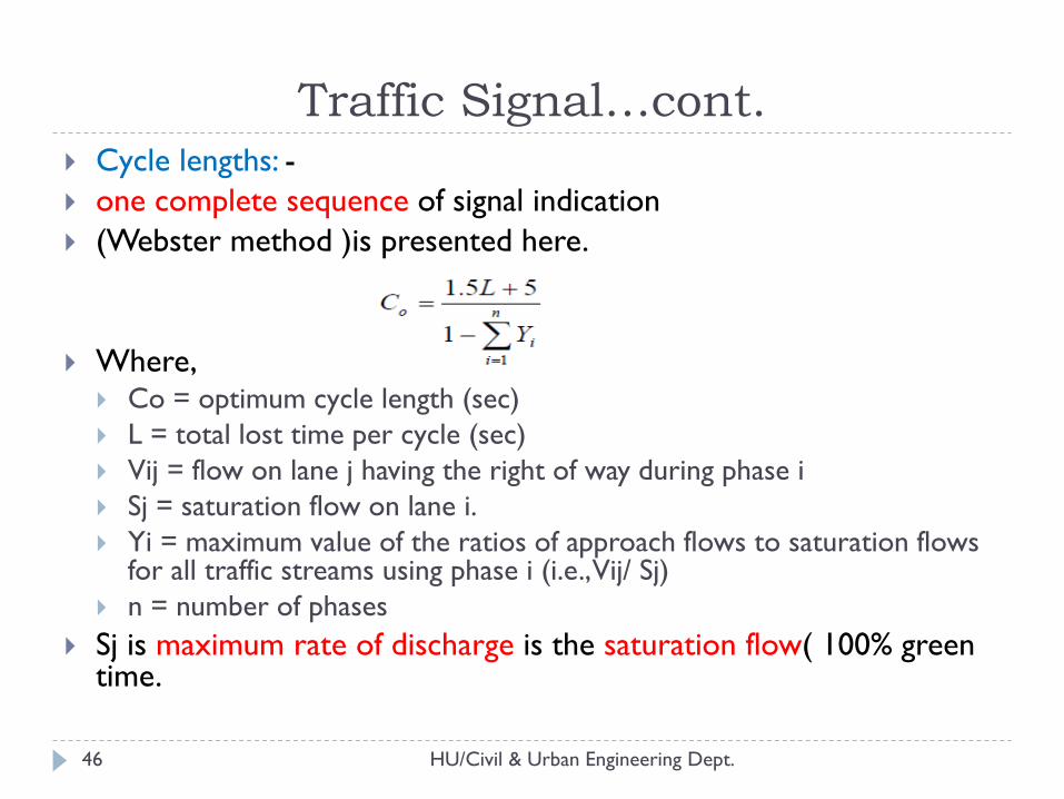
HU/Civil & Urban Engineering Dept. 46
Cycle lengths: -
one complete sequence of signal indication
(Webster method )is presented here.
Where, Co = optimum cycle length (sec)
L = total lost time per cycle (sec)
Vij = flow on lane j having the right of way during phase i
Sj = saturation flow on lane i.
Yi = maximum value of the ratios of approach flows to saturation flows for all traffic streams using phase i (i.e., Vij/ Sj)
n = number of phases
Sj is maximum rate of discharge is the saturation flow( 100% green time.
Traffic Signal…cont.
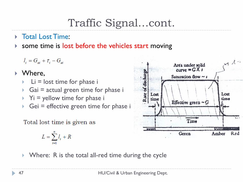
HU/Civil & Urban Engineering Dept. 47
Total Lost Time:
some time is lost before the vehicles start moving
Where, Li = lost time for phase i
Gai = actual green time for phase i
Yi = yellow time for phase i
Gei = effective green time for phase i
Where: R is the total all-red time during the cycle
Traffic Signal…cont.
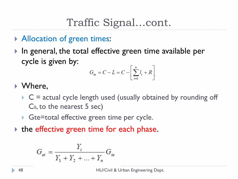
HU/Civil & Urban Engineering Dept. 48
Allocation of green times:
In general, the total effective green time available per
cycle is given by:
Where,
C = actual cycle length used (usually obtained by rounding off
C0, to the nearest 5 sec)
Gte=total effective green time per cycle.
the effective green time for each phase.
Traffic Signal…cont.
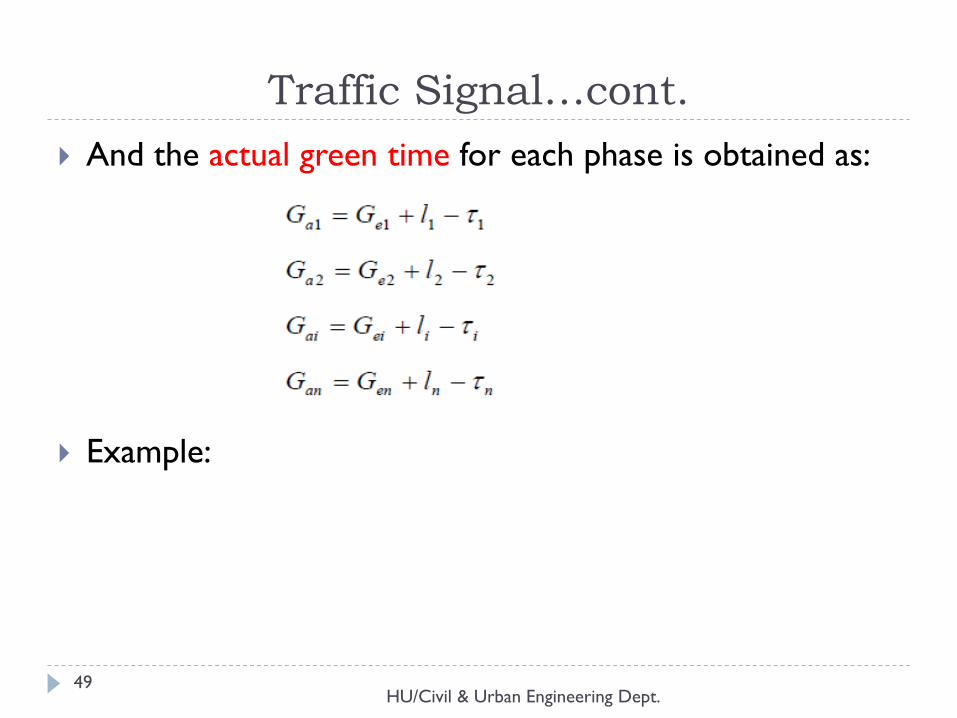
HU/Civil & Urban Engineering Dept. 49
And the actual green time for each phase is obtained as:
Example:
Traffic Signal…cont.
Terminals
ASTU/Civil Engineering Dept. 50
Terminals can be: Parking or Truck terminals
Parking facilities:
Widespread parking problems exist in business districts and other highly developed areas.
The geometric design of parking facilities mainly involves the dimension and arranging of parking bays to provide:
safe and easy across without seriously restricting the flow of traffic on the adjacent traveling lanes.
Truck terminals:
The planning and design of facilities to accommodate the loading, unloading, and parking of trucks can have a significant impact on the operational efficiency of the street and highway system
Terminals
HU/Civil & Urban Engineering Dept. 51
Types of parking facilities
On street and off street
On-street parking Facilities:
Parking bays are provided alongside the curb on one or both sides of the street.
Unrestricted parking: duration of parking is unlimited and parking is free
Restricted parking: limited to specific times of the day for the max duration and may be free or not.
Off-street Parking Facilities:
These facilities may be privately or publicly owned.
Include surface lots and garages
Self or attendant parking
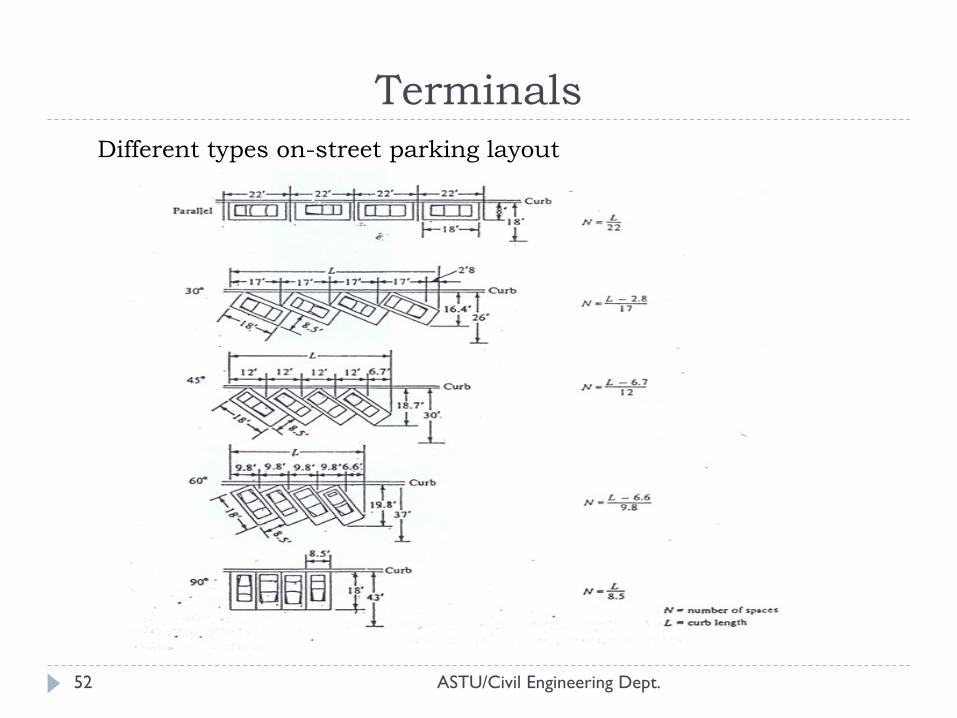
ASTU/Civil Engineering Dept. 52
Terminals
Different types on-street parking layout
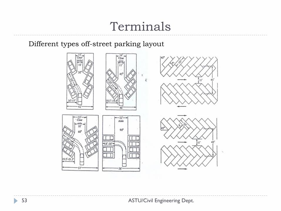
ASTU/Civil Engineering Dept. 53
Different types off-street parking layout
Terminals
Thank You!
ASTU/Civil Engineering Dept.
QUESTIONS?
54