Embed Size (px)
Citation preview
HiLight: Hiding Bits in Pixel Translucency Changes
Tianxing Li, Chuankai An, Andrew T. Campbell, and Xia ZhouDepartment of Computer Science, Dartmouth College{tianxing, chuankai, campbell, xia}@cs.dartmouth.edu
ABSTRACTWe present HiLight, a new form of screen-camera communicationwithout the need of any coded images (e.g. barcodes) for off-the-shelf smart devices. HiLight hides information underlying any im-ages shown on a LED or an OLED screen, so that camera-equippedsmart devices can fetch the information by turning their camerasto the screen. HiLight achieves this by leveraging the orthogonaltransparency (alpha) channel, a well-known concept in computergraphics, to embed bits into pixel translucency changes without theneed of modifying pixel color (RGB) values. We demonstrated Hi-Light’s feasibility using smartphones. By offering an unobtrusive,flexible, and lightweight communication channel between screensand cameras, HiLight opens up opportunities for new HCI andcontext-aware applications to emerge, e.g. smart glass communi-cates with screens for additional personalized information to realizeaugmented reality.
Categories and Subject DescriptorsC.2.1 [Network Architecture and Design]: Wireless communica-tion
KeywordsScreen-camera link; Visible light communication
1. INTRODUCTIONScreens (e.g. LED/OLED screens) and cameras are ubiquitous,
not only in laptops, but also in today’s smart devices such as smart-phones, smart watches, and smart glass. Communication betweenscreens and cameras has been attracting growing interest, where in-formation is encoded into visual frames on the screen and cameras-equipped devices extract the information from the captured frames.Operating on the visible light spectrum, screen-camera links arehighly directional and interference-free, offering a promising out-of-band communication approach for short-range information ac-quiring. The most popular example of screen-camera links is QR-Code [3], which embeds information (typically a URL) into 2D bar-
Permission to make digital or hard copies of all or part of this work for personal orclassroom use is granted without fee provided that copies are not made or distributedfor profit or commercial advantage and that copies bear this notice and the full cita-tion on the first page. Copyrights for components of this work owned by others thanACM must be honored. Abstracting with credit is permitted. To copy otherwise, or re-publish, to post on servers or to redistribute to lists, requires prior specific permissionand/or a fee. Request permissions from [email protected]’14, September 7, 2014, Maui, Hawaii, USA.Copyright 2014 ACM 978-1-4503-3067-1/14/09 ...$15.00.http://dx.doi.org/10.1145/2643164.2643171 .
codes. Recent research endeavors lead to new modulation schemeto boost data rates [14], and innovative barcodes [8, 12, 20].
While exciting, most existing screen-camera proposals rely onspecialized coded images on the screen to transmit data. Thesecoded images (e.g. barcodes) are typically visible to users. Theyeither occupy the whole screen, or interfere with the content cur-rently shown on the screen, creating an unpleasant viewing expe-rience. Recent designs aim to improve the user’s viewing expe-rience by designing unobtrusive barcodes [20], or integrating im-ages/watermark into barcodes [12, 22]. However, by modifyingpixel colors of the full image, these designs entail high complexityto transmit dynamic information in real time. Furthermore, existingdesigns require absolute color values or image features (e.g. edges)in the perceived frame to decode information, and hence are sus-ceptible to problems of image blur and frame synchronization [10].
To overcome the above limitations, we propose HiLight, a flexi-ble and robust form of screen-camera communication channel thathides information underlying any image currently shown on thescreen. The key idea of HiLight is to embed information into pixeltranslucency changes on the LED or OLED screen, so that camera-equipped devices can decode the information based on the per-ceived color intensity changes. HiLight utilizes an orthogonal trans-parency channel (alpha channel), a well-known concept in com-puter graphics, to change pixel translucency and opacity. The levelof pixel translucency change is configured so that it is perceivableto only cameras but not human eyes. Furthermore, by controllingthe translucency changes of each pixel independently, HiLight en-ables multiple transmitter elements on the screen to transmit datasimultaneously. This creates a MIMO communication channel be-tween screen and cameras [4], which can be used to boost data rateor to improve transmission reliability.
Operating on a separate transparency (alpha) channel, HiLightprovides three key benefits. First, without adding any specializedcoded images, HiLight enables unobtrusive, on-demand data trans-missions while preserving the user’s viewing experience. Second,HiLight does not require any modifications to pixel color (RGB)values of the existing image on the screen. Hence HiLight entailslow overhead to encode information and is applicable to transmitdata in real time for off-the-shelf smart devices. Third, HiLightleverages the relative changes within a time window, rather thanthe absolute values, of perceived color intensity (i.e. the summa-tion of RGB channel values) to decode information. This makes thesystem less susceptible to problems such as image blur and framesynchronization.
In the rest of this paper, we will present our initial system de-sign of HiLight, and summarize preliminary results on its feasi-bility. Using the screen and camera of off-the-shelf smartphones(Samsung S5 and Note 3), we demonstrated that HiLight is able

to achieve 11Kbps throughput at normal smartphone viewing dis-tance (30cm). Using a 50-inch TV screen, HiLight can support3m viewing distance. Our initial results also point out remainingopen challenges that we plan to tackle as ongoing work. By of-fering an unobtrusive, flexible, and lightweight hidden communi-cation channel between screens and cameras, HiLight presents op-portunities for new HCI and context-aware applications for smartdevices. For example, a user wearing smart glasses can acquire ad-ditional personalized information from the screen (e.g. TV screen,smartphone or tablet screen) without affecting the content he/sheand other users are currently viewing.
2. RELATED WORKAs a particular form of visible light communication, screen-camera
links have received increasing interests in recent years. Here wecategorize existing research on screen-camera communication intotwo main categories. The first category of work focuses on build-ing high data rate, reliable screen-camera links. PixNet [14] ap-plies orthogonal frequency division multiplexing (OFDM) to boostthe communication data rate between a LCD display and cameras.COBRA [8] and SBVLC [23] propose innovative barcodes for largedata transmissions in real-time systems. To improve link reliabil-ity, [10, 17] tackle the frame synchronization problem using era-sure coding or new preamble detection methods. All these designs,however, require obtrusive coded images shown on the screen, cre-ating unpleasant user viewing experiences. The second category ofwork aims to improve the user’s viewing experience while enablingscreen-camera communication. In [22], Yuan et al propose a water-marking approach that represents dynamic messages as coded im-ages and embeds them into the original screen image. VRCode [20]designs unobtrusive barcodes by switching some complementaryhue-based barcode at 60Hz on the display. PiCode and ViCode [12]integrate barcodes with existing images for better viewing expe-riences. IVC [6] inserts encoded messages into video and playsthe video at a high frame rate to transmit data. While these meth-ods effectively reduce the impact of visual code on human eyes,they require modifications of pixel RGB values, and lead to highencoding overhead. In our work, we aim to enable unobtrusivescreen-camera communication without the need of any coded im-ages while promoting low encoding overhead. HiLight is similarin spirit to prior efforts that modulate bits by changing the screen’sbacklight [7, 11, 13]. However, unlike these designs that requirespecial hardware support (e.g. shutter plane [7]) to enable MIMOcommunication, HiLight uses off-the-shelf smart devices to createa hidden MIMO channel.
3. HiLight DESIGNIn this section, we introduce the system design of HiLight. We
seek to achieve two goals: 1) unobtrusive data transmissions be-tween screen and cameras without using any coded images; and 2)low encoding overhead to enable on-demand, real-time data trans-mission for off-the-shelf smart devices. HiLight achieves thesegoals by leveraging a separate alpha channel to control each pixel’stranslucency and opacity changes. This represents a dramatic de-parture from existing screen-camera link designs, which encodedata into each pixel’s absolute color value. Next, we start withthe background knowledge of alpha channel, followed by designchallenges of HiLight and our initial solution.
3.1 Background and Design RationaleAlpha Channel. As a standard technique in computer graph-ics, the alpha channel has been widely used to form a composite
(a) Changing α values of thescreen from 1, 0.99, to 0.5
400 420 440 460
0.4 0.5 0.6 0.7 0.8 0.9 1
Col
or in
tens
ity
_
(b) Color intensity perceived bythe receiver (camera)
Figure 1: The impact of changing pixels’ α values. (a) shows an imagewith different α values: the default value 1 (the left), 0.99 (the middle),and 0.5 (the right), using a Samsung Note 3; (b) shows the color inten-sity of the frame captured by Samsung S5 when varying the α valueson the transmitter’s screen.
image with partial or full transparency [16]. While the image ele-ment stores the color intensity values in red, green, and blue (RGB)diodes for each pixel of the foreground image [19], the alpha chan-nel stores a value (α) between 0 and 1 to indicate the pixel translu-cency. An α value of 0 means that the foreground image pixel isfully transparent, and 1 (the default value) means that the pixel isfully opaque. Since today’s LED and OLED screens use a blackmatte as the background image, α of 0 means dimming the pixel toblack, and α of 1 means displaying the original color intensity ofthe pixel. Therefore, decreasing the α value of a pixel essentiallydims the pixel. As an example, Figure 1(a) shows the screen of aSamsung Note 3, where we uniformly set the α values of the rightpart of the screen to 0.5, resulting into a darker appearance.
This dimming effect is perceived as color intensity (summationof RGB channel values) changes by the camera (receiver). To ex-amine the resulting color intensity perceived by off-the-shelf cam-eras, we set up a Samsung Note 3 phone as the transmitter, and aSamsung S5 phone 15cm apart as the receiver. We adjust the αvalues of all pixels on the Note 3’s screen, and calculate the colorintensity at each pixel using the frame captured by S5’s camera. Asshown in Figure 1(b), increasing α value leads to a linear increaseof the color intensity perceived by the receiver’s camera. This isbecause α value is used to multiply the RGB color values. Mostimportantly, even for the α value change of 0.01 (α = 0.99), whichis not perceivable by human eyes (Figure 1(a)), the camera of S5 isable to detect the color intensity change. The results demonstratethe potential for off-the-shelf, camera-equipped smart devices todecode information embedded in pixel translucency changes.
Design Rationale of HiLight. Motivated by the above observa-tions, HiLight encodes information into pixel’s translucency (α)changes on transmitter’s LED or OLED screen. To decode theinformation, camera-equipped smart devices examine the changesof the perceived color intensity in captured frames. To make thetranslucency changes imperceptible by human eyes, HiLight changesthe α value by 0.01 (α = 0.99) to dim a pixel, and the translucencychanges as the screen refreshes. The LED or OLED screens in to-day’s smartphones support 60Hz refresh rate, which is sufficient toavoid the direct flicker effect when a user views a static image [5].Furthermore, we can divide the screen into grids, and change theα values of all pixels in each grid independently. Hence each gridfunctions as an independent transmitter element, resulting into aMIMO channel between screen and cameras. Overall, operatingon the alpha channel, HiLight provides a communication channelunobtrusive to users with low encoding overhead. Also, when di-viding screen into small grids, HiLight reduces the impact of framevertical synchronization issue [10], because each grid operates in-dependently and not all grids contain unsynchronized frame pixels.
Demodulator
Transmitter
Data
Transpancy code Alpha blending
Foreground image
Receiver
BFSK modulation
FFT
Pulse detectionBits pool
Two-fold votingReceived
data
Modulator
Figure 2: HiLight system overview.
0.99
1
0 8 16 24 32 40 48
_
Time (frame ID)
10
(a) Time domain
0
4
8
12
16
20
10 15 20 25 30 35
Pow
er o
f FFT
freq
. (dB
)
Frequency (Hz)
10
(b) Frequency domainFigure 3: Embedding bits into the frequency of pixel translucency (α value)changes. (a) shows the sequence of α values for symbols ‘01’ with 60Hz samplingrate. (b) shows the translucency changes in frequency domain for bit 0 and 1 afterapplying FFT.
3.2 Design ChallengesIn a nutshell, the efficacy of HiLight depends on its ability of
detecting small changes in pixel translucency and reliably decod-ing information under various practical settings. This is non-trivialeven for a static image because of the following challenges. First,illumination changes from ambient light and noises of camera sen-sors can interfere with the coded translucency changes. Since exist-ing smart devices have a rolling shutter speed up to 120fps and LEDdisplay refreshing rate of 60Hz, the available frequency to trans-mit data is close to DC component (0Hz), making the data decod-ing vulnerable to noises. Second, detecting translucency changesis harder for darker images with lower RGB values because thepixel’s RGB value is multiplied by an α value. Hence for a givenα change, the larger the pixel’s RGB value, the larger the absoluteRGB value change, and hence the more easily the camera can de-tect the changes. It requires us to seek solutions that reduce the sys-tem’s sensitivity to image colors. Third, to support on-demand datatransmission, the receiver needs to synchronize with the transmitterand detect the starting point of a data stream. This is challenginggiven that screen-camera communication is a one-way channel.
3.3 Initial SolutionWe now describe our initial solution to tackle the above chal-
lenges. At a high level, HiLight encodes data using FrequencyShift Keys (FSK). We judiciously design the modulation keys toavoid low frequency components close to the frequency of environ-mental noise. This reduces the impact of noise on data decoding.To detect the start and end of a data stream, HiLight aggregatesthe perceived bits of all pixels on both the time and spatial domainto reduce the impact of frame synchronization and environmentalnoise. Finally, we explore the use of erasure coding [18] to adddata redundancy and recover information in dark areas. Figure 2illustrates the flowchart of HiLight. We next introduce each stepin detail, assuming that the receiver records video at 60fps. Weintroduce HiLight with erasure coding in Section 3.4.
Modulating Data. For a given bit stream and pre-defined gridson the screen, the transmitter first modulates bits using Binary Fre-quency Shift Keying (BFSK). We select BFSK because of its sim-plicity. We are interested in exploring more advanced modulationschemes as part of future work. Here bit 0 and 1 are represented bydifferent frequency of translucency changes over a certain numberof frames (24 frames in our implementation). Figure 3(a) showsthe sequence of α values of a grid on the transmitter’s screen torepresent bit 0 and 1. Unlike Pharos [9] that keeps the duty cycle to50%, HiLight adjusts the duty cycle to remove the low frequencycomponents (< 15Hz). Hence the frequency power of the data bitwill be less affected by environmental noise.
To transmit each bit, the transmitter generates the sequence of α(translucency) values of each pixel for 24 frames. Pixels within a
-60
-40
-20
0
15 20 25 30 35
Pow
er o
f FFT
freq
. (dB
)
Frequency (Hz)
Pulse for 1
(a) Frequency pulse for bit ‘1’
-60
-40
-20
0
15 20 25 30 35
Pow
er o
f FFT
freq
. (dB
)
Frequency (Hz)
Pulse for 0
(b) Frequency pulse for bit ‘0’Figure 4: Applying FFT to the perceived color intensity values of a singlegrid over 24 frames at the receiver side. 1% change of the α values atthe transmitter side can generate distinguishable pulses in the frequencydomain for the receiver to decode data.
grid have the same α value. It then applies alpha blending method [19],a standard technique in computer graphics, using OpenGL APIto combine the foreground image with background image (blackmatte), and outputs the frames into the screen buffer.
Demodulating Data. Once the receiver captures frames in itscamera buffer, it applies Fast Fourier Transform (FFT) to projectthe translucency changes in a decoding window (24 frames) intothe frequency domain. As shown in Figure 3(b), the translucencychanges for bit 0 and 1 lead to frequency power pulses centeredon 20Hz and 30Hz respectively. Hence the receiver filters the fre-quency components below 15Hz, and checks the power of 20Hzand 30Hz frequency components. If either component has the high-est power across all frequency components above 15Hz, the re-ceiver then applies an edge detection method [21] to calculate thefirst-order derivative of this frequency component. If the absolutederivative value is above a threshold (3 in our implementation), thereceiver then outputs the corresponding bit into a candidate pool.The receiver slides the decoding window by one frame and repeatsthe above procedure.
Given all candidate bits in the bit pool, HiLight determines thereceived bit for every 24 frames as the bit with the most appear-ances. To detect the first frame of a data transmission, HiLightchecks the number of detected bits for a given frame. If more than60% of grids detect a bit, HiLight treats this frame as the first frame.Clearly, using more frames to transmit a bit helps reduce bit errorscaused by frame synchronization and environmental noises (e.g.,ambient light and camera sensor noise), and thus leads to higherdecoding accuracy at the receiver side. From our experiments, weobserve that using 24 frames can remove most bit errors. Fig-ure 4 plots the frequency components after applying FFT on theperceived color intensity values of a single grid over 24 frames.We observe that even with 1% change of the α value, a windowof 24 frames is able to generate distinguishable pulses in the fre-quency domain. The downside of using 24 frames per bit is the as-sociated delay (24/60=0.4 second) to transmit a single bit, whichlimits the data rate achieved by a single grid. An interesting open

B1
B3
B2
B4
Figure 5: An optimal block placement for an example block groupwhen K = 3. The screen is divided into 8 regions, and the 4 elementsof this block group are placed at B1, B2, B3 and B4.
problem is to design more sophisticated modulation and demodu-lation schemes that use fewer frames to transmit and decode eachbit reliably. We plan it as a future work (Section 5).
3.4 HiLight with Erasure CodingThe basic design of HiLight directly distributes data bits to grids.
Clearly for grids located in the image’s dark area, decoding thetranslucency changes is hard and leads to high bit errors. To im-prove the reliability of data transmission, we explore the use oferasure coding to add redundancy [18]. The key idea is to add nredundant bits for every m data bits. By the property of erasurecoding, the receiver can recover the m data bits if it successfullydecodes any m bits of the (m+ n) bits.
In particular, we apply Vandermonde Reed-Solomon coding [15]to encode data bits. That is, we multiply every K data bits by adistribution matrix that consists of an identity matrix and a Vander-monde matrix. Take K = 3 as an example and let di, 0 < i ≤ Kdenote each data bit, we calculate the code as the following:
⎡
⎢⎢⎣
1 0 00 1 00 0 11 1 1
⎤
⎥⎥⎦×
⎡
⎣d1d2d3
⎤
⎦ =
⎡
⎢⎢⎣
d1d2d3r
⎤
⎥⎥⎦ , (1)
where the redundant data r =∑K
i=1 di ≤ K. Since each grid cantransmit only 0 or 1, we need a block of ⌈log(K + 1)⌉ grids torepresent r. The K data grids and 1 redundant data block form ablock group, where successfully receiving any K of them allowsthe recovery of K data bits. The redundancy ratio of each blockgroup is ⌈log(K+1)⌉
K+⌈log(K+1)⌉ . When K = 3, each redundant block has 2grids, thus each block group has 2
3+2 = 40% redundancy.Now given the block groups, the next question is how to place
them on the screen. To reduce the impact of dark areas, we maxi-mally spread out the (K + 1) elements (K data grids and 1 redun-dant data block) of each block group on the screen. This minimizesthe possibility of having multiple elements in dark areas and thusmaximizes the probability of data recovery. Specifically, we firstdivide the screen into 2(K + 1) regions. We then distribute the(K + 1) elements of each block group into these regions, so thatwe maximize the minimal distance between any two elements inthe same group. Figure 5 shows an example placement for a blockgroup with data grids B1, B2, B3 and a redundant data block B4,assuming K = 3. We have proved the optimality of our placementsolution, and omit the proof in the interest of space.
4. HiLight EXPERIMENTSWe now examine the feasibility of HiLight using off-the-shelf
smart phones. We aim to understand the throughput and accuracyHiLight achieves under different practical settings. We define thethroughput as the number of bits that the receiver receives correctlyper second, and the decoding accuracy is the percentage of bitsreceived successfully over all bits transmitted.
4.1 Experimental SetupWe implemented HiLight’s modulation and demodulation in a
MATLAB emulator. The modulator takes the random bits we gen-
erated and a static image as input, and outputs a video where thedata bits are embedded into pixel translucency changes. We playthe video on a Samsung Note 3 Android phone as the transmitter,and use a Samsung S5 phone to capture the frames. These cap-tured frames are the input for the demodulator to decode transmit-ted bits. As the next step, we plan to implement the modulation anddemodulation on existing smart device for real-time encoding anddecoding (Section 5).
Figure 6 shows our experimental setup, where we fix the receiver(left) and the transmitter (right) on two phone holders. This avoidsthe problems of image alignment and image blur (we plan it for aongoing work), and allows us to focus on examining HiLight fea-sibility. Specifically, the transmitter is a Samsung Note 3 with 5.7-inch OLED display (1920 x 1080 pixels). The display is 12.6cm x7.2cm in size and its refreshing rate is 60Hz. The receiver is a Sam-sung S5 with a rear camera that has a resolution of 16 megapixelsand supports 120fps video recording. To match the refreshing rateof the display, we used 60fps at the receiver side. For all experi-ments, we used the default auto-focus function on S5’s camera torecord videos. We ignore the first 2 seconds of the video becauseof the high noise during initializing the auto-focus function.
We evaluate HiLight in terms of its accuracy and throughput.By default, we used HiLight basic design without erasure coding.We next present our preliminary results to understand the impactof image colors, grid sizes, environmental factors such as ambientlight and distance, as well as the benefits of erasure coding scheme.
4.2 Preliminary ResultsImpact of Foreground Image Color. As we discussed in Sec-tion 3.2, the color of screen’s foreground image affects camera’sability to detect color intensity changes. To understand the impactof image color on HiLight system, we tested 61 single-color imageswith colors varying from black (0, 0, 0) to white (255, 255, 255).The transmitter and receiver are 15cm away, which maximizes thearea of the transmitter’s screen in the viewfinder of the receiver’scamera and prevents the out-of-focus problem. We divided thetransmitter’s screen into grids, where each grid is 94.5mm2 in sizeand has 160x135 pixels. Using the basic HiLight design withouterasure coding, we encoded bits using each single-color image asthe foreground image, played the video on Note 3 phone’s screen,and decoded bits using the frames captured by S5’s camera. We re-peated the experiment for 5 rounds for each image. All experimentswere performed under fluorescent lamp with illuminance ≈14lux.
Figure 7(a) shows the accuracy and throughput of HiLight asa function of image color intensity. Larger color intensity indi-cates a brighter color. As expected, as the color becomes brighter,HiLight’s performance gradually stabilizes. This is because thepixel translucency changes for brighter colors lead to larger abso-lute color intensity changes, and hence are easier for the camera todetect. Overall we observe that once the color intensity is above200, HiLight achieves 90%+ accuracy and 230-240bps throughput.
We further examine the impact of color intensity distribution inthree RGB channels (red, green, and blue), by testing colors withthe same color intensity. Taking a color intensity of 30 as an ex-ample, we examined 1-channel colors such as (30, 0, 0), 2-channelcolors such as (15, 15, 0), and 3-channel colors such as (10, 10,10). Figure 7(b) shows the resulting accuracy for different RGBdistributions for each given color intensity. We observe that for2-channel and 3-channel colors, HiLight requires a higher color in-tensity (120 - 150) to achieve 80%+ accuracy and stabilize. Com-pared to 1-channel colors, 2-channel and 3-channel colors spreadthe RGB value across more channels and each color channel has a
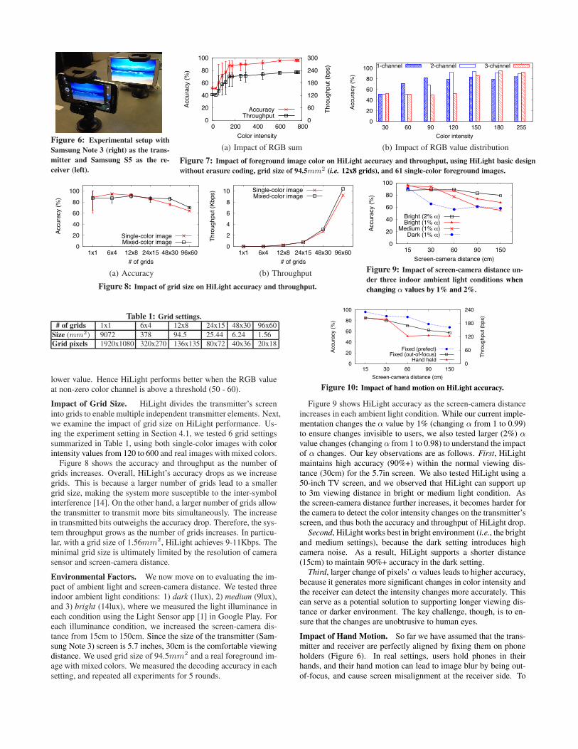
Figure 6: Experimental setup withSamsung Note 3 (right) as the trans-mitter and Samsung S5 as the re-ceiver (left).
0
20
40
60
80
100
0 200 400 600 800 0
60
120
180
240
300
Accu
racy
(%)
Thro
ughp
ut (b
ps)
Color intensity
AccuracyThroughput
(a) Impact of RGB sum
0
20
40
60
80
100
30 60 90 120 150 180 255
Accu
racy
(%)
Color intensity
1-channel 2-channel 3-channel
(b) Impact of RGB value distributionFigure 7: Impact of foreground image color on HiLight accuracy and throughput, using HiLight basic designwithout erasure coding, grid size of 94.5mm2 (i.e. 12x8 grids), and 61 single-color foreground images.
0
20
40
60
80
100
1x1 6x4 12x8 24x15 48x30 96x60
Accu
racy
(%)
# of grids
Single-color imageMixed-color image
(a) Accuracy
0
2
4
6
8
10
1x1 6x4 12x8 24x15 48x30 96x60
Thro
ughp
ut (K
bps)
# of grids
Single-color imageMixed-color image
(b) ThroughputFigure 8: Impact of grid size on HiLight accuracy and throughput.
0
20
40
60
80
100
15 30 60 90 150
Accu
racy
(%)
Screen-camera distance (cm)
Bright (2% _)Bright (1% _)
Medium (1% _)Dark (1% _)
Figure 9: Impact of screen-camera distance un-der three indoor ambient light conditions whenchanging α values by 1% and 2%.
Table 1: Grid settings.# of grids 1x1 6x4 12x8 24x15 48x30 96x60
Size (mm2) 9072 378 94.5 25.44 6.24 1.56Grid pixels 1920x1080 320x270 136x135 80x72 40x36 20x18
lower value. Hence HiLight performs better when the RGB valueat non-zero color channel is above a threshold (50 - 60).
Impact of Grid Size. HiLight divides the transmitter’s screeninto grids to enable multiple independent transmitter elements. Next,we examine the impact of grid size on HiLight performance. Us-ing the experiment setting in Section 4.1, we tested 6 grid settingssummarized in Table 1, using both single-color images with colorintensity values from 120 to 600 and real images with mixed colors.
Figure 8 shows the accuracy and throughput as the number ofgrids increases. Overall, HiLight’s accuracy drops as we increasegrids. This is because a larger number of grids lead to a smallergrid size, making the system more susceptible to the inter-symbolinterference [14]. On the other hand, a larger number of grids allowthe transmitter to transmit more bits simultaneously. The increasein transmitted bits outweighs the accuracy drop. Therefore, the sys-tem throughput grows as the number of grids increases. In particu-lar, with a grid size of 1.56mm2, HiLight achieves 9-11Kbps. Theminimal grid size is ultimately limited by the resolution of camerasensor and screen-camera distance.
Environmental Factors. We now move on to evaluating the im-pact of ambient light and screen-camera distance. We tested threeindoor ambient light conditions: 1) dark (1lux), 2) medium (9lux),and 3) bright (14lux), where we measured the light illuminance ineach condition using the Light Sensor app [1] in Google Play. Foreach illuminance condition, we increased the screen-camera dis-tance from 15cm to 150cm. Since the size of the transmitter (Sam-sung Note 3) screen is 5.7 inches, 30cm is the comfortable viewingdistance. We used grid size of 94.5mm2 and a real foreground im-age with mixed colors. We measured the decoding accuracy in eachsetting, and repeated all experiments for 5 rounds.
0
20
40
60
80
100
15 30 60 90 150 0
60
120
180
240
Accu
racy
(%)
Thro
ughp
ut (b
ps)
Screen-camera distance (cm)
Fixed (prefect)Fixed (out-of-focus)
Hand held
Figure 10: Impact of hand motion on HiLight accuracy.
Figure 9 shows HiLight accuracy as the screen-camera distanceincreases in each ambient light condition. While our current imple-mentation changes the α value by 1% (changing α from 1 to 0.99)to ensure changes invisible to users, we also tested larger (2%) αvalue changes (changing α from 1 to 0.98) to understand the impactof α changes. Our key observations are as follows. First, HiLightmaintains high accuracy (90%+) within the normal viewing dis-tance (30cm) for the 5.7in screen. We also tested HiLight using a50-inch TV screen, and we observed that HiLight can support upto 3m viewing distance in bright or medium light condition. Asthe screen-camera distance further increases, it becomes harder forthe camera to detect the color intensity changes on the transmitter’sscreen, and thus both the accuracy and throughput of HiLight drop.
Second, HiLight works best in bright environment (i.e., the brightand medium settings), because the dark setting introduces highcamera noise. As a result, HiLight supports a shorter distance(15cm) to maintain 90%+ accuracy in the dark setting.
Third, larger change of pixels’ α values leads to higher accuracy,because it generates more significant changes in color intensity andthe receiver can detect the intensity changes more accurately. Thiscan serve as a potential solution to supporting longer viewing dis-tance or darker environment. The key challenge, though, is to en-sure that the changes are unobtrusive to human eyes.
Impact of Hand Motion. So far we have assumed that the trans-mitter and receiver are perfectly aligned by fixing them on phoneholders (Figure 6). In real settings, users hold phones in theirhands, and their hand motion can lead to image blur by being out-of-focus, and cause screen misalignment at the receiver side. To
50
60
70
80
90
100
0 10 20 30 40 50 60
Accu
racy
(%)
Percentage of dark area (%)
w/ erasure codingBasic
(a) Accuracy
0 50
100 150 200 250
0 10 20 30 40 50 60
Thro
ughp
ut (b
ps)
Percentage of dark area (%)
Basicw/ erasure coding
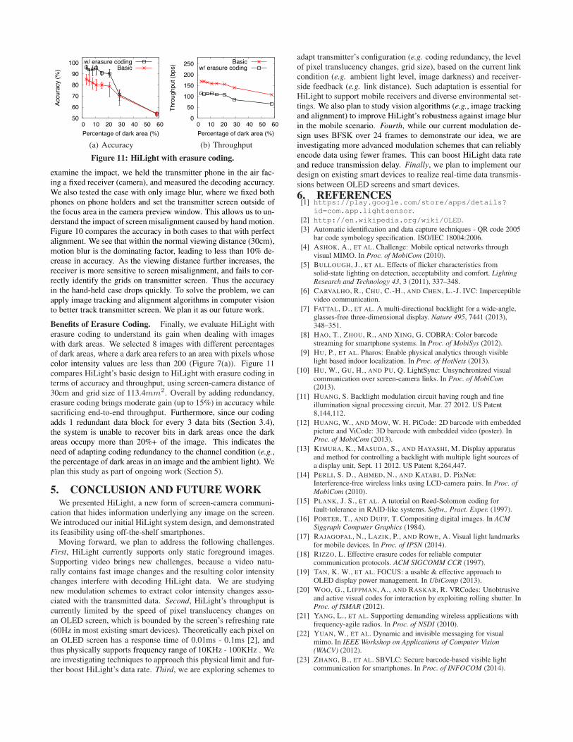
(b) ThroughputFigure 11: HiLight with erasure coding.
examine the impact, we held the transmitter phone in the air fac-ing a fixed receiver (camera), and measured the decoding accuracy.We also tested the case with only image blur, where we fixed bothphones on phone holders and set the transmitter screen outside ofthe focus area in the camera preview window. This allows us to un-derstand the impact of screen misalignment caused by hand motion.Figure 10 compares the accuracy in both cases to that with perfectalignment. We see that within the normal viewing distance (30cm),motion blur is the dominating factor, leading to less than 10% de-crease in accuracy. As the viewing distance further increases, thereceiver is more sensitive to screen misalignment, and fails to cor-rectly identify the grids on transmitter screen. Thus the accuracyin the hand-held case drops quickly. To solve the problem, we canapply image tracking and alignment algorithms in computer visionto better track transmitter screen. We plan it as our future work.
Benefits of Erasure Coding. Finally, we evaluate HiLight witherasure coding to understand its gain when dealing with imageswith dark areas. We selected 8 images with different percentagesof dark areas, where a dark area refers to an area with pixels whosecolor intensity values are less than 200 (Figure 7(a)). Figure 11compares HiLight’s basic design to HiLight with erasure coding interms of accuracy and throughput, using screen-camera distance of30cm and grid size of 113.4mm2. Overall by adding redundancy,erasure coding brings moderate gain (up to 15%) in accuracy whilesacrificing end-to-end throughput. Furthermore, since our codingadds 1 redundant data block for every 3 data bits (Section 3.4),the system is unable to recover bits in dark areas once the darkareas occupy more than 20%+ of the image. This indicates theneed of adapting coding redundancy to the channel condition (e.g.,the percentage of dark areas in an image and the ambient light). Weplan this study as part of ongoing work (Section 5).
5. CONCLUSION AND FUTURE WORKWe presented HiLight, a new form of screen-camera communi-
cation that hides information underlying any image on the screen.We introduced our initial HiLight system design, and demonstratedits feasibility using off-the-shelf smartphones.
Moving forward, we plan to address the following challenges.First, HiLight currently supports only static foreground images.Supporting video brings new challenges, because a video natu-rally contains fast image changes and the resulting color intensitychanges interfere with decoding HiLight data. We are studyingnew modulation schemes to extract color intensity changes asso-ciated with the transmitted data. Second, HiLight’s throughput iscurrently limited by the speed of pixel translucency changes onan OLED screen, which is bounded by the screen’s refreshing rate(60Hz in most existing smart devices). Theoretically each pixel onan OLED screen has a response time of 0.01ms - 0.1ms [2], andthus physically supports frequency range of 10KHz - 100KHz . Weare investigating techniques to approach this physical limit and fur-ther boost HiLight’s data rate. Third, we are exploring schemes to
adapt transmitter’s configuration (e.g. coding redundancy, the levelof pixel translucency changes, grid size), based on the current linkcondition (e.g. ambient light level, image darkness) and receiver-side feedback (e.g. link distance). Such adaptation is essential forHiLight to support mobile receivers and diverse environmental set-tings. We also plan to study vision algorithms (e.g., image trackingand alignment) to improve HiLight’s robustness against image blurin the mobile scenario. Fourth, while our current modulation de-sign uses BFSK over 24 frames to demonstrate our idea, we areinvestigating more advanced modulation schemes that can reliablyencode data using fewer frames. This can boost HiLight data rateand reduce transmission delay. Finally, we plan to implement ourdesign on existing smart devices to realize real-time data transmis-sions between OLED screens and smart devices.6. REFERENCES[1] https://play.google.com/store/apps/details?
id=com.app.lightsensor.[2] http://en.wikipedia.org/wiki/OLED.[3] Automatic identification and data capture techniques - QR code 2005
bar code symbology specification. ISO/IEC 18004:2006.[4] ASHOK, A., ET AL. Challenge: Mobile optical networks through
visual MIMO. In Proc. of MobiCom (2010).[5] BULLOUGH, J., ET AL. Effects of flicker characteristics from
solid-state lighting on detection, acceptability and comfort. LightingResearch and Technology 43, 3 (2011), 337–348.
[6] CARVALHO, R., CHU, C.-H., AND CHEN, L.-J. IVC: Imperceptiblevideo communication.
[7] FATTAL, D., ET AL. A multi-directional backlight for a wide-angle,glasses-free three-dimensional display. Nature 495, 7441 (2013),348–351.
[8] HAO, T., ZHOU, R., AND XING, G. COBRA: Color barcodestreaming for smartphone systems. In Proc. of MobiSys (2012).
[9] HU, P., ET AL. Pharos: Enable physical analytics through visiblelight based indoor localization. In Proc. of HotNets (2013).
[10] HU, W., GU, H., AND PU, Q. LightSync: Unsynchronized visualcommunication over screen-camera links. In Proc. of MobiCom(2013).
[11] HUANG, S. Backlight modulation circuit having rough and fineillumination signal processing circuit, Mar. 27 2012. US Patent8,144,112.
[12] HUANG, W., AND MOW, W. H. PiCode: 2D barcode with embeddedpicture and ViCode: 3D barcode with embedded video (poster). InProc. of MobiCom (2013).
[13] KIMURA, K., MASUDA, S., AND HAYASHI, M. Display apparatusand method for controlling a backlight with multiple light sources ofa display unit, Sept. 11 2012. US Patent 8,264,447.
[14] PERLI, S. D., AHMED, N., AND KATABI, D. PixNet:Interference-free wireless links using LCD-camera pairs. In Proc. ofMobiCom (2010).
[15] PLANK, J. S., ET AL. A tutorial on Reed-Solomon coding forfault-tolerance in RAID-like systems. Softw., Pract. Exper. (1997).
[16] PORTER, T., AND DUFF, T. Compositing digital images. In ACMSiggraph Computer Graphics (1984).
[17] RAJAGOPAL, N., LAZIK, P., AND ROWE, A. Visual light landmarksfor mobile devices. In Proc. of IPSN (2014).
[18] RIZZO, L. Effective erasure codes for reliable computercommunication protocols. ACM SIGCOMM CCR (1997).
[19] TAN, K. W., ET AL. FOCUS: a usable & effective approach toOLED display power management. In UbiComp (2013).
[20] WOO, G., LIPPMAN, A., AND RASKAR, R. VRCodes: Unobtrusiveand active visual codes for interaction by exploiting rolling shutter. InProc. of ISMAR (2012).
[21] YANG, L., ET AL. Supporting demanding wireless applications withfrequency-agile radios. In Proc. of NSDI (2010).
[22] YUAN, W., ET AL. Dynamic and invisible messaging for visualmimo. In IEEE Workshop on Applications of Computer Vision(WACV) (2012).
[23] ZHANG, B., ET AL. SBVLC: Secure barcode-based visible lightcommunication for smartphones. In Proc. of INFOCOM (2014).