Embed Size (px)
Citation preview

※ History List
Version Date Update Information
1.0 ’15.02.27 - 2015 New EHS SPLIT TDB Released. (Modify the Spec Note)
1.1 ‘15.03.06- Modify : Note(Spec, Capacity Table) / Electric Diagram / OD Drawing Mixing Valve
- Add : Mixing Valve Page / DHW Oper. Rnage
1.2 ‘15.04.06- Modify : Sound Pressure
- Add : SCOP / ESEER
1.3 ‘15.06.10 - Modify : Typing Error (Outdoor Power)
1.4 ‘15.06.15 - Modify : Change the Note for Refrigerant
1.5 ‘15.06.22 - Modify : Change the Shipping Dimension for Hydro
1.6 ‘15.08.27 - Add : System capacity for Max & Min

EHSTechnical Data BookEHS Split for Europe
Model : AE***JNYDEH/EU
AE***JXEDEH/EU

I. Products
1. Nomenclature …….……………………….…….………… 4
2. Line-up ……………………….…………….……….……… 6
3. System Specification……………………………………… 7
II. Outdoor Unit
1. Specifications ………………...……..…...….…..………. 12
2. Capacity Tables ………....................……….….………. 16
3. Capacity Correction ……...……………………………… 19
4. Dimensional Drawings ………...………..………………. 20
5. Cycle Diagrams …………………………………………. 23
6. Wiring Diagrams ……………...…..…………………..…. 25
7. Electric Specifications ………….…………………….… 28
8. Sound Pressure Level …..………………………………. 29
9. Operation Range …….……………..……………………. 32
III. Hydro Unit
1. Specifications ……..………..…...……….…..…..……… 34
2. Dimensional Drawings ………...………..………………. 36
3. Cycle Diagrams …………………………………………. 37
4. Wiring Diagrams ……………...…..……..………………. 38
5. Electric Specifications ………….……….……………… 40
6. Hydraulic Performance …….…………….……………… 43
IV. Application
Application Examples ……...…………..…..…..……… 45
Mixing Valve…………………...…………..…..…..……… 47

1. Nomenclature …….……………………….…….………… 4
2. Line-up ……………………….…………….……….……… 6
3. System Specification……………………………………… 7
I. Products

EHS Split I. Products
1-1. Outdoor Unit
1. Nomenclature
4
AE 060 / EU
Model Name (New)
(1) (2) (3) (4) (5) (6) (7) (Buyer)
(2) Capacity
x 1/10 kW (3 digits)
(4) Product Type
N Indoor
X Outdoor
(1) Classification
AE EHS
(5) Type
E Single (EHS)
(6) Feature 1
D DELUXE (Basic)
J
(3) Version
J 2015
X E D E H
(8)
(8) Mode
H Heat Pump R410A
(7) Rating Voltage
E 1Φ, 220~240V, 50Hz
G 3Φ, 380~415V, 50Hz

EHS Split I. Products
1-2. Indoor Unit
1. Nomenclature
5
(2) Capacity
x 1/10 kW (3 digits)
(5) Type
Y Hydro Unit (Wall Mounted)
B Hydro Unit (Floor Standing)
X Cylinder Unit
W Water Tank
(1) Classification I
AE EHS
(6) Feature 1
D STANDRAD
(7) Rating Voltage
E 1Φ, 220~240V, 50Hz
G 3Φ, 380~415V, 50Hz
AE 090 / EU
Model Name (New)
(1) (2) (3) (4) (5) (6) (7) (Buyer)
J N Y D E H
(8)
(3) Version
J 2015
(4) Product Type
N Indoor
X Outdoor
(8) Mode
H Heat Pump R410A

EHS Split I. Products
2-1. Outdoor Unit
2. Line-up
6
Split Type
Capacity (kW)
4.0 6.0 9.0 12.0 14.0 16.0
Single
Phase● ● ● ● ● ●
3 Phase ● ● ● ●
2-2. Indoor Unit
Hydro Unit
Capacity (kW)
9.0 16.0
Single
Phase● ●
3 Phase ● ●
2-3. Combination Table
Outdoor Unit Hydro Unit
Model Name Type AE090JNYDEH/** AE090JNYDGH/** AE160JNYDEH/** AE160JNYDGH/**
AE040JXEDEH/EU Reversible ●
AE060JXEDEH/EU Reversible ●
AE090JXEDEH/EU Reversible ●
AE120JXEDEH/EU Reversible ●
AE140JXEDEH/EU Reversible ●
AE160JXEDEH/EU Reversible ●
AE090JXEDGH/EU Reversible ●
AE120JXEDGH/EU Reversible ●
AE140JXEDGH/EU Reversible ●
AE160JXEDGH/EU Reversible ●

EHS Split I. Products
3. System Specification
Model
Name
Indoor Unit AE090JNYDEH/EU AE090JNYDEH/EU AE090JNYDEH/EU
Outdoor Unit AE040JXEDEH/EU AE060JXEDEH/EU AE090JXEDEH/EU
System
Mode - Heat Pump (A2W) Heat Pump (A2W) Heat Pump (A2W)
Performance
(A7/W35) *1
Nominal Capacity
Heating
(Min/Std/Max)
W 1,667/4,400/4,000 1,667/6,000/6,000 2,394/9,000 /9,000
Btu/h 5,700 / 15,000 / 15,000 5,700 / 20,500 / 20,500 8,200 / 30,700 / 30,700
Cooling
(Min/Std/Max)
W 1,625 / 5,000 / 5,000 1,625 / 6,500 / 6,500 1,818 / 8,000 / 8,000
Btu/h 5,500 / 17,100 / 17,100 5,500 / 22,200 / 22,200 6,200 / 27,300 / 27,300
Power Input
(Nominal)
Heating
(Min/Std/Max)W
348 / 860 / 860 348 / 1,250 / 1,250 535 / 2,010 / 2,010
Cooling
(Min/Std/Max)438 / 1,260 / 1,260 438 / 1,750 / 1,750 500 / 2,200 / 2,200
Current Input
(Nominal)
Heating
(Min/Std/Max)A
1.6 / 4.1 / 4.1 1.6 / 5.7 / 5.7 2.5 / 9.2 / 9.2
Cooling
(Min/Std/Max)2.0 / 5.7 / 5.7 2.0 / 8.0 / 8.0 2.3 / 10.1 / 10.1
COP (Nominal Heating) W/W 5.10 4.80 4.48
EER (Nominal Cooling) W/W 3.97 3.71 3.64
SCOP 4.522 4.539 4.577
ESEER 5.367 5.349 4.789
Performance
(A2/W35) *2
Capacity Heating W 3400 4600 7700
COP W/W 3.52 3.31 3.38
Performance
(A-7/W35) *3
Capacity Heating W 3750 5100 7600
COP W/W 2.62 2.49 2.45
Field
Wiring
MCA A 20 20 22
MFA A 25 25 27.5
Water
Connections
Water Flow Rate (Heating / Cooling) LPM 13/15 17/20 26/25
Water Pressure (Max) bar 3 3 3
Water Pipe Inlet Φ, inch BSPP male 1 1/4" BSPP male 1 1/4" BSPP male 1 1/4"
Outlet Φ, inch BSPP male 1 1/4" BSPP male 1 1/4" BSPP male 1 1/4"
Leaving Water
Temperature
Heating °C 25~55 25~55 25~55
Cooling °C 5~25 5~25 5~25
Refrigerant
Connections
Liquid Pipe Φ, mm 6.35 6.35 6.35
Φ, inch 1/4" 1/4" 1/4"
Gas Pipe Φ, mm 15.88 15.88 15.88
Φ, inch 5/8" 5/8" 5/8"
Installation
Limitation
Max. Length m 30 30 50
Max. Height m 20 20 30
Chargeless Length m 15 15 15
Operating
Temp. Range
Heating (A2W) *4 ℃ -25~35 -25~35 -25~35
Cooling (A2W) ℃ 10~46 10~46 10~46
DHW (A2W) *5 ℃ -25~43 -25~43 -25~43
*1) A2W Condition #1 : (Heating) Water In/Out 30℃/35℃, Outdoor Air 7℃DB/6℃WB; (Cooling) Water In/Out 23℃/18℃, Outdoor Air 35℃DB.
*2) A2W Condition #2 : (Heating) Water In/Out 30℃/35℃, Outdoor Air 2℃DB
*3) A2W Condition #3 : (Heating) Water In/Out 30℃/35℃, Outdoor Air -7℃DB
*4) The system is operated in ( -25℃ ≤ Outdoor temp <-20℃) condition, but no guarantee of capacity.
*5) The system is operated by only Booster Heater in special condition( 35℃ < Outdoor temp. ≤ 43℃).
7

EHS Split I. Products
3. System Specification
Model
Name
Indoor Unit AE160JNYDEH/EU AE160JNYDEH/EU AE160JNYDEH/EU
Outdoor Unit AE120JXEDEH/EU AE140JXEDEH/EU AE160JXEDEH/EU
System
Mode - Heat Pump (A2W) Heat Pump (A2W) Heat Pump (A2W)
Performance
(A7/W35) *1
Nominal Capacity
Heating
(Min/Std/Max)
W 3,750 / 12,000 / 12,000 3,750 / 14,000 / 14,000 3,750 / 16,000 / 16,000
Btu/h 12,800 / 40,900 / 40,900 12,800 / 47,800 / 47,800 12,800 / 54,600 / 54,600
Cooling
(Min/Std/Max)
W 3,300 / 12,000 / 12,000 3,300 / 14,000 / 14,000 3,300 / 15,000 / 15,000
Btu/h 11,300 / 40,900 / 40,900 11,300 / 47,800 / 47,800 11,300 / 51,200 / 51,200
Power Input
(Nominal)
Heating
(Min/Std/Max)W
809 / 2,590 / 2,590 809 / 3,150 / 3,150 809 / 3,760 / 3,760
Cooling
(Min/Std/Max)853 / 3,100 / 3,100 853 / 3,800 / 3,800 853 / 4,140 / 4,140
Current Input
(Nominal)
Heating
(Min/Std/Max)A
3.7 / 11.7 / 11.7 3.7 / 14.3 / 14.3 3.7 / 16.9 / 16.9
Cooling
(Min/Std/Max)3.9 / 14.0 / 14.0 3.9 / 17.0 / 17.0 3.9 / 18.6 / 18.6
COP (Nominal Heating) W/W 4.63 4.44 4.26
EER (Nominal Cooling) W/W 3.87 3.68 3.62
SCOP 4.627 4.560 4.515
ESEER 4.933 4.906 4.906
Performance
(A2/W35) *2Capacity Heating W 9800 11200 12500
COP W/W 3.28 3.25 3.14
Performance
(A-7/W35) *3Capacity Heating W 10,300 11,800 13,400
COP W/W 2.57 2.55 2.50
Field
Wiring
MCA A 28 30 32
MFA A 35 37.5 40
Water
Connections
Water Flow Rate (Heating / Cooling) LPM 35/35 40/40 46/44
Water Pressure (Max) bar 3 3 3
Water Pipe Inlet Φ, inch BSPP male 1 1/4" BSPP male 1 1/4" BSPP male 1 1/4"
Outlet Φ, inch BSPP male 1 1/4" BSPP male 1 1/4" BSPP male 1 1/4"
Leaving Water
Temperature
Heating °C 25~55 25~55 25~55
Cooling °C 5~25 5~25 5~25
Refrigerant
Connections
Liquid Pipe Φ, mm 9.52 9.52 9.52
Φ, inch 3/8" 3/8" 3/8"
Gas Pipe Φ, mm 15.88 15.88 15.88
Φ, inch 5/8" 5/8" 5/8"
Installation
Limitation
Max. Length m 50 50 50
Max. Height m 30 30 30
Chargeless Length m 15 15 15
Operating
Temp. Range
Heating (A2W) *4 ℃ -25~35 -25~35 -25~35
Cooling (A2W) ℃ 10~46 10~46 10~46
DHW (A2W) *5 ℃ -25~43 -25~43 -25~43
8
*1) A2W Condition #1 : (Heating) Water In/Out 30℃/35℃, Outdoor Air 7℃DB/6℃WB; (Cooling) Water In/Out 23℃/18℃, Outdoor Air 35℃DB.
*2) A2W Condition #2 : (Heating) Water In/Out 30℃/35℃, Outdoor Air 2℃DB
*3) A2W Condition #3 : (Heating) Water In/Out 30℃/35℃, Outdoor Air -7℃DB
*4) The system is operated in ( -25℃ ≤ Outdoor temp <-20℃) condition, but no guarantee of capacity.
*5) The system is operated by only Booster Heater in special condition( 35℃ < Outdoor temp. ≤ 43℃).

EHS Split I. Products
Model
Name
Indoor Unit AE090JNYDGH/EU AE160JNYDGH/EU AE160JNYDGH/EU
Outdoor Unit AE090JXEDGH/EU AE120JXEDGH/EU AE140JXEDGH/EU
System
Mode - Heat Pump (A2W) Heat Pump (A2W) Heat Pump (A2W)
Performance
(A7/W35) *1
Nominal Capacity
Heating
(Min/Std/Max)
W 2,475 / 9,000 / 9,000 3,750 / 12,000 / 12,000 3,750 / 14,000 / 14,000
Btu/h 8,400 / 30,700 / 30,700 12,800 / 40,900 / 40,900 12,800 / 47,800 / 47,800
Cooling
(Min/Std/Max)
W 1,875 / 7,500 / 7,500 3,300 / 12,000 / 12,000 3,300 / 14,000 / 14,000
Btu/h 6,400 / 25,600 / 25,600 3,300 / 40,900 / 40,900 3,300 / 47,800 / 47,800
Power Input
(Nominal)
Heating
(Min/Std/Max)W
553 / 2,010 / 2,010 809 / 2,590 / 2,590 809 / 3,150 / 3,150
Cooling
(Min/Std/Max)515 / 2,060 / 2,060 853 / 3,100 / 3,100 853 / 3,800 / 3,800
Current Input
(Nominal)
Heating
(Min/Std/Max)A
0.9 / 3.3 / 3.3 1.3 / 4.1 / 4.1 1.3 / 4.7 / 4.7
Cooling
(Min/Std/Max)0.9 / 3.4 / 3.4 1.3 / 4.7 / 4.7 1.3 / 5.7 / 5.7
COP (Nominal Heating) W/W 4.48 4.63 4.44
EER (Nominal Cooling) W/W 3.64 3.87 3.68
SCOP 4.569 4.717 4.733
ESEER 4.648 4.933 4.906
Performance
(A2/W35) *2Capacity Heating W 7700 9800 11200
COP W/W 3.38 3.28 3.25
Performance
(A-7/W35) *3Capacity Heating W 7600 10,300 11,800
COP W/W 2.45 2.57 2.55
Field
Wiring
MCA A 10 10 11
MFA A 16.1 16.1 16.1
Water
Connections
Water Flow Rate (Heating / Cooling) LPM 26/22 35/35 40/40
Water Pressure (Max) bar 3 3 3
Water Pipe Inlet Φ, inch BSPP male 1 1/4" BSPP male 1 1/4" BSPP male 1 1/4"
Outlet Φ, inch BSPP male 1 1/4" BSPP male 1 1/4" BSPP male 1 1/4"
Leaving Water
Temperature
Heating °C 25~55 25~55 25~55
Cooling °C 5~25 5~25 5~25
Refrigerant
Connections
Liquid Pipe Φ, mm 6.35 9.52 9.52
Φ, inch 1/4" 3/8" 3/8"
Gas Pipe Φ, mm 15.88 15.88 15.88
Φ, inch 5/8" 5/8" 5/8"
Installation
Limitation
Max. Length m 50 50 50
Max. Height m 30 30 30
Chargeless Length m 15 15 15
Operating
Temp. Range
Heating (A2W) *4 ℃ -25~35 -25~35 -25~35
Cooling (A2W) ℃ 10~46 10~46 10~46
DHW (A2W) *5 ℃ -25~43 -25~43 -25~43
3. System Specification
9
*1) A2W Condition #1 : (Heating) Water In/Out 30℃/35℃, Outdoor Air 7℃DB/6℃WB; (Cooling) Water In/Out 23℃/18℃, Outdoor Air 35℃DB.
*2) A2W Condition #2 : (Heating) Water In/Out 30℃/35℃, Outdoor Air 2℃DB
*3) A2W Condition #3 : (Heating) Water In/Out 30℃/35℃, Outdoor Air -7℃DB
*4) The system is operated in ( -25℃ ≤ Outdoor temp <-20℃) condition, but no guarantee of capacity.
*5) The system is operated by only Booster Heater in special condition( 35℃ < Outdoor temp. ≤ 43℃).

EHS Split I. Products
Model
Name
Indoor Unit AE160JNYDGH/EU
Outdoor Unit AE160JXEDGH/EU
System
Mode - Heat Pump (A2W)
Performance
(A7/W35) *1
Nominal Capacity
Heating
(Min/Std/Max)
W 3,750 / 16,000 / 16,000
Btu/h 12,800 / 54,600 / 54,600
Cooling
(Min/Std/Max)
W 3,300 / 15,000 / 15,000
Btu/h 3,300 / 51,200 / 51,200
Power Input
(Nominal)
Heating
(Min/Std/Max)W
809 / 3,760 / 3,760
Cooling
(Min/Std/Max)853 / 4,140 / 4,140
Current Input
(Nominal)
Heating
(Min/Std/Max)A
1.3 / 5.7 / 5.7
Cooling
(Min/Std/Max)1.3 / 6.2 / 6.2
COP (Nominal Heating) W/W 4.26
EER (Nominal Cooling) W/W 3.62
SCOP 4.697
ESEER 4.906
Performance
(A2/W35) *2Capacity Heating W 12500
COP W/W 3.14
Performance
(A-7/W35) *3Capacity Heating W 13,400
COP W/W 2.50
Field
Wiring
MCA A 12
MFA A 16.1
Water
Connections
Water Flow Rate (Heating / Cooling) LPM 46/44
Water Pressure (Max) bar 3
Water Pipe Inlet Φ, inch BSPP male 1 1/4"
Outlet Φ, inch BSPP male 1 1/4"
Leaving Water
Temperature
Heating °C 25~55
Cooling °C 5~25
Refrigerant
Connections
Liquid Pipe Φ, mm 9.52
Φ, inch 3/8"
Gas Pipe Φ, mm 15.88
Φ, inch 5/8"
Installation
Limitation
Max. Length m 50
Max. Height m 30
Chargeless Length m 15
Operating
Temp. Range
Heating (A2W) *4 ℃ -25~35
Cooling (A2W) ℃ 10~46
DHW (A2W) *5 ℃ -25~43
10
*1) A2W Condition #1 : (Heating) Water In/Out 30℃/35℃, Outdoor Air 7℃DB/6℃WB; (Cooling) Water In/Out 23℃/18℃, Outdoor Air 35℃DB.
*2) A2W Condition #2 : (Heating) Water In/Out 30℃/35℃, Outdoor Air 2℃DB
*3) A2W Condition #3 : (Heating) Water In/Out 30℃/35℃, Outdoor Air -7℃DB
*4) The system is operated in ( -25℃ ≤ Outdoor temp <-20℃) condition, but no guarantee of capacity.
*5) The system is operated by only Booster Heater in special condition( 35℃ < Outdoor temp. ≤ 43℃).
3. System Specification

II. Outdoor Unit
1. Specifications ………………...……..…...….…..………. 12
2. Capacity Tables ………....................……….….………. 16
3. Capacity Correction ……...……………………………… 19
4. Dimensional Drawings ………...………..………………. 20
5. Cycle Diagrams …………………………………………. 23
6. Wiring Diagrams ……………...…..…………………..…. 25
7. Electric Specifications ………….…………………….… 28
8. Sound Pressure Level …..………………………………. 29
9. Operation Range …….……………..……………………. 32

II. Outdoor UnitEHS Split
12
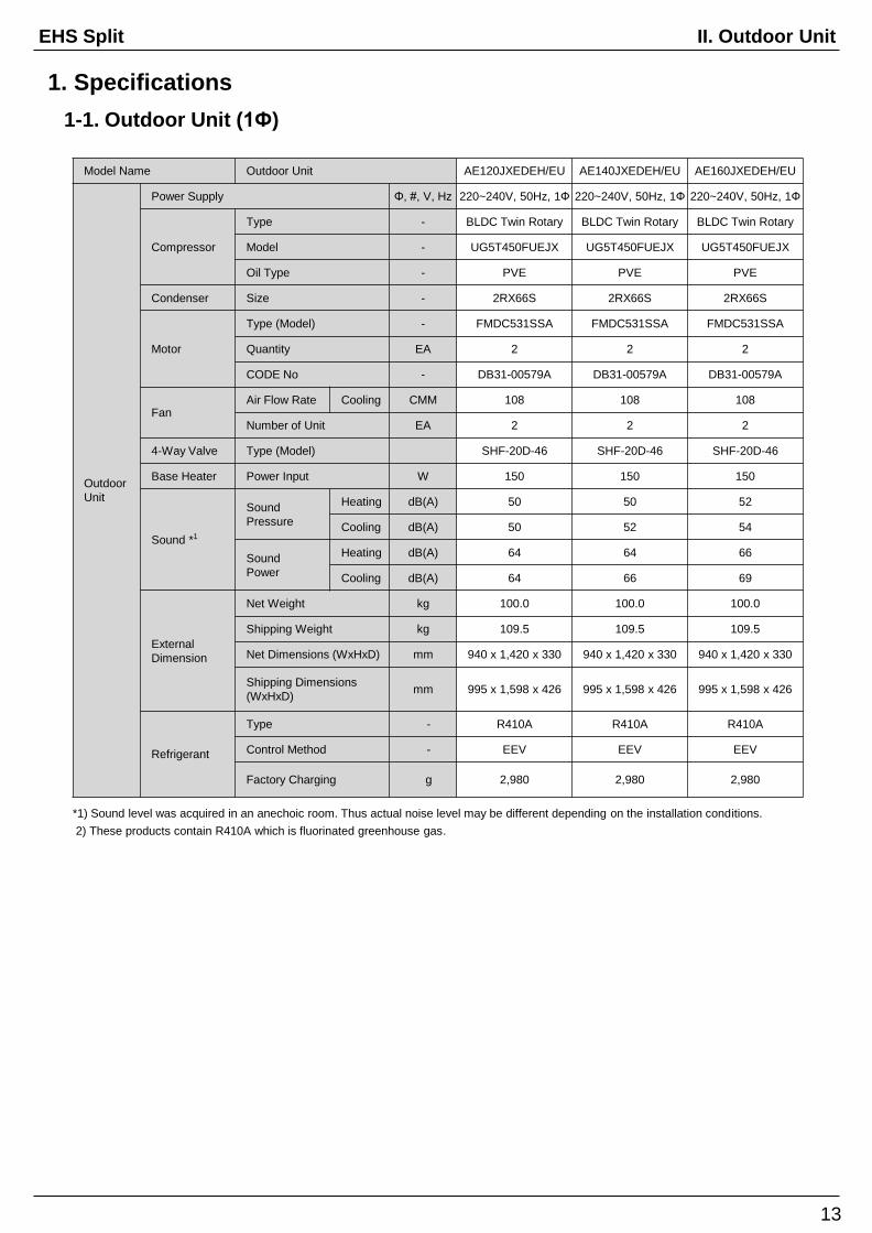
1. Specifications
1-1. Outdoor Unit (1Ф)
Model Name Outdoor Unit AE040JXEDEH/EU AE060JXEDEH/EU AE090JXEDEH/EU
Outdoor
Unit
Power Supply Φ, #, V, Hz 220~240V, 50Hz, 1Ф 220~240V, 50Hz, 1Ф 220~240V, 50Hz, 1Ф
Compressor
Type - BLDC Twin Rotary BLDC Twin Rotary BLDC Twin Rotary
Model - UG4TH8200FE4SG UG4TH8200FE4SG UG8TH8265FJW
Oil Type - POE POE POE
Condenser Size - 2RX28S 2RX28S 2RX46S
Motor
Type (Model) - SIC-67FV-F135-2 SIC-67FV-F135-2 FMDC531SSA
Quantity EA 1 1 1
CODE No - DB31-00492A DB31-00492A DB31-00579A
FanAir Flow Rate Cooling CMM 40 43 53
Number of Unit EA 1 1 1
4-Way Valve Type (Model) SHF-7H-34U SHF-7H-34U SHF-11H
Base Heater Power Input W X X 150
Sound *1
Sound
Pressure
Heating dB(A) 46 47 49
Cooling dB(A) 46 47 50
Sound
Power
Heating dB(A) 61 61 64
Cooling dB(A) 63 63 63
External
Dimension
Net Weight kg 48.5 48.5 68.0
Shipping Weight kg 51.5 51.5 78.0
Net Dimensions (WxHxD) mm 880 x 638 x 310 880 x 638 x 310 940 x 998 x 330
Shipping Dimensions
(WxHxD)mm 1,023 x 725 x 413 1,023 x 725 x 413 995 x 1,178 x 426
Refrigerant
Type - R410A R410A R410A
Control Method - EEV EEV EEV
Factory Charging g 1,400 1,400 1,700
*1) Sound level was acquired in an anechoic room. Thus actual noise level may be different depending on the installation conditions.
2) These products contain R410A which is fluorinated greenhouse gas.
II. Outdoor UnitEHS Split
13
1. Specifications
Model Name Outdoor Unit AE120JXEDEH/EU AE140JXEDEH/EU AE160JXEDEH/EU
Outdoor
Unit
Power Supply Φ, #, V, Hz 220~240V, 50Hz, 1Ф 220~240V, 50Hz, 1Ф 220~240V, 50Hz, 1Ф
Compressor
Type - BLDC Twin Rotary BLDC Twin Rotary BLDC Twin Rotary
Model - UG5T450FUEJX UG5T450FUEJX UG5T450FUEJX
Oil Type - PVE PVE PVE
Condenser Size - 2RX66S 2RX66S 2RX66S
Motor
Type (Model) - FMDC531SSA FMDC531SSA FMDC531SSA
Quantity EA 2 2 2
CODE No - DB31-00579A DB31-00579A DB31-00579A
FanAir Flow Rate Cooling CMM 108 108 108
Number of Unit EA 2 2 2
4-Way Valve Type (Model) SHF-20D-46 SHF-20D-46 SHF-20D-46
Base Heater Power Input W 150 150 150
Sound *1
Sound
Pressure
Heating dB(A) 50 50 52
Cooling dB(A) 50 52 54
Sound
Power
Heating dB(A) 64 64 66
Cooling dB(A) 64 66 69
External
Dimension
Net Weight kg 100.0 100.0 100.0
Shipping Weight kg 109.5 109.5 109.5
Net Dimensions (WxHxD) mm 940 x 1,420 x 330 940 x 1,420 x 330 940 x 1,420 x 330
Shipping Dimensions
(WxHxD)mm 995 x 1,598 x 426 995 x 1,598 x 426 995 x 1,598 x 426
Refrigerant
Type - R410A R410A R410A
Control Method - EEV EEV EEV
Factory Charging g 2,980 2,980 2,980
1-1. Outdoor Unit (1Ф)
*1) Sound level was acquired in an anechoic room. Thus actual noise level may be different depending on the installation conditions.
2) These products contain R410A which is fluorinated greenhouse gas.

II. Outdoor UnitEHS Split
14
1. Specifications
1-2. Outdoor Unit (3Ф)
Model Name Outdoor Unit AE090JXEDGH/EU AE120JXEDGH/EU
Outdoor
Unit
Power Supply Φ, #, V, Hz 380~415V, 50Hz, 3Ф 380~415V, 50Hz, 3Ф
Compressor
Type - BLDC Twin Rotary BLDC Twin Rotary
Model - UG8T300FUCJU UG5T450FUFJX
Oil Type - PVE PVE
Condenser Size - 2RX46S 2RX66S
Motor
Type (Model) - FMDC531SSA FMDC531SSA
Quantity EA 1 2
CODE No - DB31-00579A DB31-00579A
FanAir Flow Rate Cooling CMM 53 108
Number of Unit EA 1 2
4-Way Valve Type (Model) SHF-11H SHF-20D-46
Base Heater Power Input W 150 150
Sound *
Sound
Pressure
Heating dB(A) 49 50
Cooling dB(A) 50 50
Sound
Power
Heating dB(A) 64 64
Cooling dB(A) 63 64
External
Dimension
Net Weight kg 76.0 101.5
Shipping Weight kg 84.5 111.0
Net Dimensions (WxHxD) mm 940 x 998 x 330 940 x 1,420 x 330
Shipping Dimensions
(WxHxD)mm 995 x 1,178 x 426 995 x 1,598 x 426
Refrigerant
Type - R410A R410A
Control Method - EEV EEV
Factory Charging g 1,900 2,980
*1) Sound level was acquired in an anechoic room. Thus actual noise level may be different depending on the installation conditions.
2) These products contain R410A which is fluorinated greenhouse gas.

II. Outdoor UnitEHS Split
1. Specifications
Model Name Outdoor Unit AE140JXEDGH/EU AE160JXEDGH/EU
Outdoor
Unit
Power Supply Φ, #, V, Hz 380~415V, 50Hz, 3Ф 380~415V, 50Hz, 3Ф
Compressor
Type - BLDC Twin Rotary BLDC Twin Rotary
Model - UG5T450FUFJX UG5T450FUFJX
Oil Type - PVE PVE
Condenser Size - 2RX66S 2RX66S
Motor
Type (Model) - FMDC531SSA FMDC531SSA
Quantity EA 2 2
CODE No - DB31-00579A DB31-00579A
FanAir Flow Rate Cooling CMM 108 108
Number of Unit EA 2 2
4-Way Valve Type (Model) SHF-20D-46 SHF-20D-46
Base Heater Power Input W 150 150
Sound *1
Sound
Pressure
Heating dB(A) 50 52
Cooling dB(A) 52 54
Sound
Power
Heating dB(A) 64 66
Cooling dB(A) 66 69
External
Dimension
Net Weight kg 101.5 101.5
Shipping Weight kg 111.0 111.0
Net Dimensions (WxHxD) mm 940 x 1,420 x 330 940 x 1,420 x 330
Shipping Dimensions
(WxHxD)mm 995 x 1,598 x 426 995 x 1,598 x 426
Refrigerant
Type - R410A R410A
Control Method - EEV EEV
Factory Charging g 2,980 2,980
1-2. Outdoor Unit (3Ф)
15
*1) Sound level was acquired in an anechoic room. Thus actual noise level may be different depending on the installation conditions.
2) These products contain R410A which is fluorinated greenhouse gas.

II. Outdoor UnitEHS Split
AE
040JX
ED
EH
/EU
LWT (℃) 25 30 35 40 45 50 55
Tamb (℃) HC(kW) PI(kW) HC(kW) PI(kW) HC(kW) PI(kW) HC(kW) PI(kW) HC(kW) PI(kW) HC(kW) PI(kW) HC(kW) PI(kW)
-20 3.35 1.02 3.39 1.30 3.43 1.59 3.48 1.88
-15 3.65 1.02 3.69 1.30 3.74 1.59 3.80 1.88 3.86 2.18
-10 3.82 1.00 3.93 1.28 5.51 1.56 4.19 1.85 4.33 2.14 4.50 2.44 4.68 2.74
-7 3.92 0.99 4.07 1.27 4.24 1.55 4.42 1.83 4.62 2.12 4.83 2.41 5.08 2.71
-2 4.18 0.86 4.32 1.11 4.47 1.36 4.63 1.62 4.80 1.88 4.99 2.14 5.20 2.40
2 4.29 0.71 4.41 0.92 4.53 1.14 4.67 1.36 4.82 1.59 4.98 1.81 5.15 2.04
7 4.60 0.52 4.50 0.69 4.40 0.86 4.30 1.03 4.20 1.20 4.10 1.37 4.00 1.54
10 4.73 0.53 4.64 0.70 4.56 0.87 4.47 1.05 4.38 1.22 4.30 1.39 4.21 1.56
15 4.95 0.55 4.89 0.72 4.82 0.90 4.75 1.07 4.69 1.24 4.62 1.42 4.56 1.59
20 5.17 0.57 5.13 0.75 5.08 0.92 5.04 1.10 4.99 1.27 4.95 1.44 4.90 1.62
AE
060JX
ED
EH
/EU
LWT (℃) 25 30 35 40 45 50 55
Tamb (℃) HC(kW) PI(kW) HC(kW) PI(kW) HC(kW) PI(kW) HC(kW) PI(kW) HC(kW) PI(kW) HC(kW) PI(kW) HC(kW) PI(kW)
-20 4.82 1.74 4.74 2.00 4.66 2.27 4.59 2.54
-15 5.22 1.74 5.15 2.00 5.09 2.27 5.02 2.54 4.97 2.81
-10 5.49 1.71 5.49 1.97 5.51 2.24 5.54 2.50 5.57 2.77 5.62 3.04 5.69 3.31
-7 5.64 1.69 5.70 1.95 5.77 2.21 5.84 2.48 5.94 2.74 6.05 3.01 6.17 3.27
-2 5.99 1.49 6.02 1.72 6.06 1.95 6.11 2.19 6.17 2.42 6.25 2.66 6.33 2.90
2 6.10 1.24 6.11 1.44 6.13 1.64 6.16 1.85 6.19 2.05 6.24 2.26 6.29 2.46
7 6.60 0.95 6.30 1.10 6.00 1.25 5.70 1.40 5.40 1.55 5.10 1.70 4.80 1.85
10 6.79 0.97 6.50 1.12 6.21 1.27 5.92 1.42 5.64 1.57 5.35 1.72 5.06 1.87
15 7.12 1.00 6.85 1.15 6.57 1.30 6.30 1.45 6.03 1.61 5.75 1.76 5.48 1.91
20 7.44 1.04 7.19 1.19 6.93 1.34 6.67 1.49 6.42 1.64 6.16 1.79 5.91 1.94
AE
090JX
ED
*H/E
U
LWT (℃) 25 30 35 40 45 50 55
Tamb (℃) HC(kW) PI(kW) HC(kW) PI(kW) HC(kW) PI(kW) HC(kW) PI(kW) HC(kW) PI(kW) HC(kW) PI(kW) HC(kW) PI(kW)
-20 7.16 2.76 6.99 3.10 6.83 3.44 6.66 3.78
-15 7.81 2.76 7.66 3.10 7.51 3.44 7.36 3.78 7.21 4.13
-10 8.26 2.71 8.22 3.05 9.33 3.39 8.16 3.72 8.15 4.06 8.16 4.40 8.18 5.10
-7 8.52 2.69 8.55 3.02 8.59 3.35 8.65 3.68 8.72 4.02 8.81 4.35 8.93 5.10
-2 9.67 2.49 9.61 2.77 9.56 3.05 9.52 3.34 9.49 3.62 9.48 3.90 9.48 4.18
2 10.55 2.24 10.41 2.47 10.27 2.69 10.13 2.92 10.01 3.15 9.89 3.37 9.78 3.60
7 9.40 1.52 9.20 1.77 9.00 2.01 8.80 2.26 8.60 2.50 8.40 2.75 8.20 2.99
10 9.94 1.59 9.74 1.84 9.54 2.08 9.34 2.33 9.14 2.57 8.94 2.82 8.75 3.06
15 10.83 1.71 10.64 1.95 10.44 2.20 10.24 2.45 10.05 2.69 9.85 2.94 9.66 3.18
20 11.73 1.83 11.53 2.07 11.34 2.32 11.15 2.56 10.95 2.81 10.76 3.06 10.57 3.30
AE
120JX
ED
*H/E
U
LWT (℃) 25 30 35 40 45 50 55
Tamb (℃) HC(kW) PI(kW) HC(kW) PI(kW) HC(kW) PI(kW) HC(kW) PI(kW) HC(kW) PI(kW) HC(kW) PI(kW) HC(kW) PI(kW)
-20 9.84 3.38 9.55 3.91 9.26 4.45 8.96 4.99
-15 10.73 3.38 10.45 3.91 10.17 4.45 9.90 4.99 9.63 5.53
-10 11.27 3.33 11.17 3.85 11.25 4.37 11.02 4.90 10.97 5.44 10.93 5.97 10.92 6.48
-7 11.59 3.30 11.61 3.81 11.64 4.33 11.70 4.85 11.77 5.38 11.87 5.91 12.01 6.44
-2 12.55 3.02 12.55 3.50 12.56 3.97 12.59 4.45 12.64 4.93 12.71 5.42 12.81 5.90
2 13.06 2.68 13.06 3.11 13.07 3.53 13.09 3.96 13.13 4.39 13.18 4.83 13.26 5.26
7 12.50 1.95 12.25 2.27 12.00 2.59 11.75 2.91 11.50 3.23 11.25 3.55 11.00 3.87
10 13.05 1.97 12.81 2.29 12.58 2.61 12.34 2.93 12.10 3.25 11.86 3.57 11.62 3.89
15 13.97 2.00 13.75 2.32 13.54 2.64 13.32 2.96 13.10 3.29 12.88 3.61 12.66 3.93
20 14.89 2.03 14.69 2.35 14.50 2.68 14.30 3.00 14.10 3.32 13.90 3.64 13.70 3.96
AE
140JX
ED
*H/E
U
LWT (℃) 25 30 35 40 45 50 55
Tamb (℃) HC(kW) PI(kW) HC(kW) PI(kW) HC(kW) PI(kW) HC(kW) PI(kW) HC(kW) PI(kW) HC(kW) PI(kW) HC(kW) PI(kW)
-20 11.44 4.07 11.02 4.60 10.58 5.13 10.15 5.66
-15 12.46 4.07 12.05 4.60 11.64 5.13 11.23 5.66 10.82 6.20
-10 13.14 4.01 12.92 4.53 12.60 5.05 12.50 5.57 12.31 6.10 12.13 6.62 11.96 6.94
-7 13.54 3.97 13.43 4.48 13.34 5.00 13.26 5.52 13.20 6.04 13.16 6.56 13.14 6.94
-2 14.66 3.64 14.51 4.11 14.37 4.58 14.25 5.06 14.14 5.53 14.04 6.01 13.97 6.48
2 15.26 3.23 15.09 3.65 14.93 4.07 14.78 4.50 14.64 4.92 14.52 5.35 14.41 5.78
7 15.00 2.55 14.50 2.85 14.00 3.15 13.50 3.45 13.00 3.75 12.50 4.05 12.00 4.35
10 15.69 2.57 15.19 2.87 14.69 3.17 14.19 3.47 13.69 3.77 13.19 4.07 12.69 4.37
15 16.85 2.61 16.35 2.91 15.85 3.21 15.35 3.51 14.85 3.81 14.35 4.11 13.85 4.41
20 18.00 2.64 17.50 2.94 17.00 3.24 16.50 3.54 16.00 3.84 15.50 4.14 15.00 4.44
AE
160JX
ED
*H/E
U
LWT (℃) 25 30 35 40 45 50 55
Tamb (℃) HC(kW) PI(kW) HC(kW) PI(kW) HC(kW) PI(kW) HC(kW) PI(kW) HC(kW) PI(kW) HC(kW) PI(kW) HC(kW) PI(kW)
-20 12.82 4.73 12.42 5.34 12.03 5.95 11.63 6.57
-15 13.97 4.73 13.60 5.34 13.23 5.95 12.86 6.57 12.49 7.18
-10 14.75 4.64 14.58 5.25 14.40 5.85 14.28 6.46 14.16 7.07 14.05 7.40 13.96 7.40
-7 15.23 4.59 15.18 5.19 15.15 5.79 15.14 6.39 15.15 7.00 15.20 7.61 15.28 7.40
-2 16.30 4.22 16.23 4.76 16.18 5.30 16.15 5.85 16.14 6.40 16.16 6.95 16.20 7.50
2 16.77 3.74 16.71 4.22 16.67 4.71 16.64 5.19 16.63 5.68 16.64 6.16 16.68 6.65
7 16.70 2.98 16.35 3.37 16.00 3.76 15.65 4.15 15.30 4.54 14.95 4.93 14.60 5.32
10 17.58 3.00 17.24 3.39 16.90 3.78 16.56 4.17 16.22 4.56 15.88 4.95 15.54 5.34
15 19.05 3.03 18.73 3.42 18.40 3.82 18.07 4.21 17.75 4.60 17.42 4.99 17.10 5.38
20 20.52 3.07 20.21 3.46 19.90 3.85 19.59 4.24 19.28 4.63 18.97 5.02 18.66 5.41
16
2. Capacity Tables
LWT (Leaving Water Temp.), Tamb (Ambient Temp.), HC (Heating Capacity), PI (Power input)
2-1. AE040/060/090/120/140/160JXED*H/EU
1) Maximum Heating Capacity (Peak Value)
1. Heating capacity : Capacity is according to Eurovent rating standard OM-3-2015 and valid for heated water range △t = 3∼8°C
2. Cooling capacity : Capacity is according to Eurovent rating standard OM-3-2015 and valid for chilled water range △t = 3∼8°C
3. Power input : Power input is according to Eurovent rating standard OM-3-2015.
4. Peak value : Tested without defrost operation in accordance with EN14511
※ The real capacity would be changed according to the install environment.

II. Outdoor UnitEHS Split
17
2. Capacity Tables
2) Maximum Heating Capacity (Integrated Value)
2-1. AE040/060/090/120/140/160JXED*H/EU
AE
040JX
ED
EH
/EU
LWT (℃) 25 30 35 40 45 50 55
Tamb (℃) HC(kW) PI(kW) HC(kW) PI(kW) HC(kW) PI(kW) HC(kW) PI(kW) HC(kW) PI(kW) HC(kW) PI(kW) HC(kW) PI(kW)
-20 3.09 0.98 3.06 1.22 3.03 1.47 3.00 1.71
-15 3.37 0.98 3.34 1.22 3.31 1.47 3.28 1.71 3.25 1.96
-10 3.52 0.96 3.55 1.21 3.58 1.45 3.61 1.69 3.65 1.93 3.68 2.17 3.71 2.41
-7 3.62 0.96 3.68 1.19 3.75 1.43 3.82 1.67 3.88 1.91 3.95 2.15 4.02 2.38
-2 3.47 0.79 3.52 0.99 3.58 1.20 3.63 1.41 3.68 1.61 3.74 1.82 3.79 2.02
2 3.31 0.62 3.36 0.79 3.40 0.97 3.44 1.14 3.49 1.32 3.53 1.49 3.57 1.67
7 4.60 0.52 4.50 0.69 4.40 0.86 4.30 1.03 4.20 1.20 4.10 1.37 4.00 1.54
10 4.73 0.53 4.64 0.70 4.56 0.87 4.47 1.05 4.38 1.22 4.30 1.39 4.21 1.56
15 4.95 0.55 4.89 0.72 4.82 0.90 4.75 1.07 4.69 1.24 4.62 1.42 4.56 1.59
20 5.17 0.57 5.13 0.75 5.08 0.92 5.04 1.10 4.99 1.27 4.95 1.44 4.90 1.62
AE
060JX
ED
EH
/EU
LWT (℃) 25 30 35 40 45 50 55
Tamb (℃) HC(kW) PI(kW) HC(kW) PI(kW) HC(kW) PI(kW) HC(kW) PI(kW) HC(kW) PI(kW) HC(kW) PI(kW) HC(kW) PI(kW)
-20 4.45 1.68 4.29 1.89 4.13 2.10 3.96 2.32
-15 4.82 1.68 4.66 1.89 4.50 2.10 4.34 2.32 4.18 2.53
-10 5.06 1.65 4.97 1.86 4.88 2.07 4.78 2.28 4.69 2.49 4.59 2.70 4.50 2.91
-7 5.21 1.63 5.15 1.84 5.10 2.05 5.05 2.26 4.99 2.46 4.94 2.67 4.88 2.88
-2 4.96 1.36 4.91 1.54 4.85 1.72 4.79 1.90 4.74 2.08 4.68 2.26 4.63 2.44
2 4.72 1.08 4.66 1.23 4.60 1.39 4.54 1.54 4.48 1.70 4.42 1.86 4.37 2.01
7 6.60 0.95 6.30 1.10 6.00 1.25 5.70 1.40 5.40 1.55 5.10 1.70 4.80 1.85
10 6.79 0.97 6.50 1.12 6.21 1.27 5.92 1.42 5.64 1.57 5.35 1.72 5.06 1.87
15 7.12 1.00 6.85 1.15 6.57 1.30 6.30 1.45 6.03 1.61 5.75 1.76 5.48 1.91
20 7.44 1.04 7.19 1.19 6.93 1.34 6.67 1.49 6.42 1.64 6.16 1.79 5.91 1.94
AE
090JX
ED
*H/E
U
LWT (℃) 25 30 35 40 45 50 55
Tamb (℃) HC(kW) PI(kW) HC(kW) PI(kW) HC(kW) PI(kW) HC(kW) PI(kW) HC(kW) PI(kW) HC(kW) PI(kW) HC(kW) PI(kW)
-20 6.61 2.66 6.33 2.92 6.04 3.18 5.75 3.45
-15 7.21 2.66 6.93 2.92 6.64 3.18 6.35 3.45 6.07 3.71
-10 7.62 2.62 7.43 2.88 7.24 3.13 7.05 3.39 6.86 3.65 6.67 3.91 6.48 4.16
-7 7.87 2.59 7.73 2.85 7.60 3.10 7.47 3.36 7.33 3.61 7.20 3.87 7.07 4.12
-2 8.01 2.27 7.83 2.48 7.65 2.69 7.47 2.90 7.29 3.11 7.11 3.32 6.92 3.53
2 8.16 1.95 7.93 2.11 7.70 2.28 7.47 2.44 7.24 2.61 7.01 2.77 6.78 2.94
7 9.40 1.52 9.20 1.77 9.00 2.01 8.80 2.26 8.60 2.50 8.40 2.75 8.20 2.99
10 9.94 1.59 9.74 1.84 9.54 2.08 9.34 2.33 9.14 2.57 8.94 2.82 8.75 3.06
15 10.83 1.71 10.64 1.95 10.44 2.20 10.24 2.45 10.05 2.69 9.85 2.94 9.66 3.18
20 11.73 1.83 11.53 2.07 11.34 2.32 11.15 2.56 10.95 2.81 10.76 3.06 10.57 3.30
AE
120JX
ED
*H/E
U
LWT (℃) 25 30 35 40 45 50 55
Tamb (℃) HC(kW) PI(kW) HC(kW) PI(kW) HC(kW) PI(kW) HC(kW) PI(kW) HC(kW) PI(kW) HC(kW) PI(kW) HC(kW) PI(kW)
-20 9.09 3.26 8.64 3.69 8.19 4.12 7.74 4.54
-15 9.90 3.26 9.45 3.69 9.00 4.12 8.55 4.54 8.10 4.97
-10 10.40 3.21 10.11 3.63 9.81 4.05 9.52 4.47 9.23 4.89 8.93 5.31 8.64 5.73
-7 10.70 3.18 10.50 3.59 10.30 4.01 10.10 4.42 9.90 4.84 9.70 5.25 9.50 5.67
-2 10.40 2.76 10.23 3.13 10.05 3.50 9.88 3.87 9.70 4.24 9.53 4.61 9.35 4.98
2 10.10 2.34 9.95 2.66 9.80 2.99 9.65 3.31 9.50 3.64 9.35 3.97 9.20 4.29
7 12.50 1.95 12.25 2.27 12.00 2.59 11.75 2.91 11.50 3.23 11.25 3.55 11.00 3.87
10 13.05 1.97 12.81 2.29 12.58 2.61 12.34 2.93 12.10 3.25 11.86 3.57 11.62 3.89
15 13.97 2.00 13.75 2.32 13.54 2.64 13.32 2.96 13.10 3.29 12.88 3.61 12.66 3.93
20 14.89 2.03 14.69 2.35 14.50 2.68 14.30 3.00 14.10 3.32 13.90 3.64 13.70 3.96
AE
140JX
ED
*H/E
U
LWT (℃) 25 30 35 40 45 50 55
Tamb (℃) HC(kW) PI(kW) HC(kW) PI(kW) HC(kW) PI(kW) HC(kW) PI(kW) HC(kW) PI(kW) HC(kW) PI(kW) HC(kW) PI(kW)
-20 10.56 3.93 9.96 4.34 9.36 4.75 8.76 5.16
-15 11.50 3.93 10.90 4.34 10.30 4.75 9.70 5.16 9.10 5.57
-10 12.13 3.87 11.68 4.27 11.24 4.67 10.79 5.08 10.35 5.48 9.91 5.88 9.46 6.29
-7 12.50 3.83 12.15 4.23 11.80 4.63 11.45 5.03 11.10 5.43 10.75 5.83 10.40 6.23
-2 12.15 3.32 11.83 3.68 11.50 4.04 11.18 4.40 10.85 4.75 10.53 5.11 10.20 5.47
2 11.80 2.81 11.50 3.13 11.20 3.45 10.90 3.76 10.60 4.08 10.30 4.40 10.00 4.71
7 15.00 2.55 14.50 2.85 14.00 3.15 13.50 3.45 13.00 3.75 12.50 4.05 12.00 4.35
10 15.69 2.57 15.19 2.87 14.69 3.17 14.19 3.47 13.69 3.77 13.19 4.07 12.69 4.37
15 16.85 2.61 16.35 2.91 15.85 3.21 15.35 3.51 14.85 3.81 14.35 4.11 13.85 4.41
20 18.00 2.64 17.50 2.94 17.00 3.24 16.50 3.54 16.00 3.84 15.50 4.14 15.00 4.44
AE
160JX
ED
*H/E
U
LWT (℃) 25 30 35 40 45 50 55
Tamb (℃) HC(kW) PI(kW) HC(kW) PI(kW) HC(kW) PI(kW) HC(kW) PI(kW) HC(kW) PI(kW) HC(kW) PI(kW) HC(kW) PI(kW)
-20 11.83 4.56 11.23 5.04 10.64 5.51 10.04 5.98
-15 12.89 4.56 12.30 5.04 11.70 5.51 11.10 5.98 10.51 6.46
-10 13.62 4.48 13.19 4.95 12.76 5.42 12.33 5.89 11.91 6.35 11.48 6.82 11.05 7.29
-7 14.06 4.43 13.73 4.89 13.40 5.36 13.07 5.83 12.74 6.29 12.42 6.76 12.09 7.22
-2 13.51 3.84 13.23 4.26 12.95 4.67 12.67 5.08 12.39 5.50 12.11 5.91 11.83 6.33
2 12.96 3.26 12.73 3.62 12.50 3.98 12.27 4.34 12.04 4.70 11.80 5.06 11.57 5.43
7 16.70 2.98 16.35 3.37 16.00 3.76 15.65 4.15 15.30 4.54 14.95 4.93 14.60 5.32
10 17.58 3.00 17.24 3.39 16.90 3.78 16.56 4.17 16.22 4.56 15.88 4.95 15.54 5.34
15 19.05 3.03 18.73 3.42 18.40 3.82 18.07 4.21 17.75 4.60 17.42 4.99 17.10 5.38
20 20.52 3.07 20.21 3.46 19.90 3.85 19.59 4.24 19.28 4.63 18.97 5.02 18.66 5.41
LWT (Leaving Water Temp.), Tamb (Ambient Temp.), HC (Heating Capacity), PI (Power input)
1. Heating capacity : Capacity is according to Eurovent rating standard OM-3-2015 and valid for heated water range △t = 3∼8°C
2. Cooling capacity : Capacity is according to Eurovent rating standard OM-3-2015 and valid for chilled water range △t = 3∼8°C
3. Power input : Power input is according to Eurovent rating standard OM-3-2015.
4. Integrated value : Tested with defrost operation in accordance with EN14511
※ The real capacity would be changed according to the install environment.

II. Outdoor UnitEHS Split
18
2. Capacity Tables
LWT (Leaving Water Temp.), Tamb (Ambient Temp.), CC (Cooling Capacity), PI (Power input)
3) Maximum Cooling Capacity
2-1. AE040/060/090/120/140/160JXED*H/EU
1. Heating capacity is according to Eurovent rating standard OM-3-2015 and valid for heated water range △t = 3∼8°C
2. Cooling capacity is according to Eurovent rating standard OM-3-2015 and valid for chilled water range △t = 3∼8°C
3. Power input is total of indoor and outdoor unit, according to Eurovent rating standard OM-3-2015.
※ The real capacity would be changed according to the install environment.
AE
040JX
ED
EH
/EU
LWT (℃) 7 10 13 15 18 26
Tamb (℃) HC(kW) PI(kW) HC(kW) PI(kW) HC(kW) PI(kW) HC(kW) PI(kW) HC(kW) PI(kW) HC(kW) PI(kW)
10 4.42 0.92 4.80 0.94 5.18 0.96 5.43 0.97 5.82 0.98 6.71 1.02
20 4.09 1.03 4.47 1.05 4.85 1.07 5.11 1.08 5.49 1.09 6.38 1.13
30 3.76 1.14 4.14 1.16 4.53 1.18 4.78 1.19 5.16 1.20 6.05 1.24
35 3.60 1.20 3.98 1.22 4.36 1.23 4.62 1.24 5.00 1.26 5.89 1.30
46 3.24 1.32 3.62 1.34 4.00 1.35 4.26 1.37 4.64 1.38 5.53 1.42
AE
060JX
ED
EH
/EU
LWT (℃) 7 10 13 15 18 26
Tamb (℃) HC(kW) PI(kW) HC(kW) PI(kW) HC(kW) PI(kW) HC(kW) PI(kW) HC(kW) PI(kW) HC(kW) PI(kW)
10 5.76 1.35 6.26 1.35 6.75 1.35 7.07 1.35 7.56 1.35 8.71 1.35
20 5.34 1.51 5.83 1.51 6.32 1.51 6.65 1.51 7.14 1.51 8.28 1.51
30 4.91 1.67 5.40 1.67 5.89 1.67 6.22 1.67 6.71 1.67 7.86 1.67
35 4.70 1.75 5.19 1.75 5.68 1.75 6.01 1.75 6.50 1.75 7.65 1.75
46 4.23 1.93 4.72 1.93 5.21 1.93 5.54 1.93 6.03 1.93 7.18 1.93
AE
090JX
ED
*H/E
U
LWT (℃) 7 10 13 15 18 25
Tamb (℃) HC(kW) PI(kW) HC(kW) PI(kW) HC(kW) PI(kW) HC(kW) PI(kW) HC(kW) PI(kW) HC(kW) PI(kW)
10 8.41 1.36 9.01 1.37 9.61 1.38 10.01 1.39 10.61 1.41 12.01 1.44
20 7.37 1.67 7.97 1.69 8.57 1.70 8.97 1.71 9.57 1.72 10.97 1.76
30 6.32 1.99 6.92 2.00 7.52 2.02 7.92 2.03 8.52 2.04 9.92 2.07
35 5.80 2.15 6.40 2.16 7.00 2.18 7.40 2.19 8.00 2.20 9.40 2.23
46 4.65 2.50 5.25 2.51 5.85 2.53 6.25 2.54 6.85 2.55 8.25 2.58
AE
12
0JX
ED
*H/E
U
LWT (℃) 7 10 13 15 18 25
Tamb (℃) HC(kW) PI(kW) HC(kW) PI(kW) HC(kW) PI(kW) HC(kW) PI(kW) HC(kW) PI(kW) HC(kW) PI(kW)
10 11.95 1.90 12.77 1.90 13.58 1.90 14.13 1.90 14.95 1.90 16.86 1.90
20 10.77 2.38 11.59 2.38 12.40 2.38 12.95 2.38 13.77 2.38 15.68 2.38
30 9.59 2.86 10.41 2.86 11.23 2.86 11.77 2.86 12.59 2.86 14.50 2.86
35 9.00 3.10 9.82 3.10 10.64 3.10 11.18 3.10 12.00 3.10 13.91 3.10
46 7.70 3.63 8.52 3.63 9.34 3.63 9.89 3.63 10.70 3.63 12.61 3.63
AE
140JX
ED
*H/E
U
LWT (℃) 7 10 13 15 18 25
Tamb (℃) HC(kW) PI(kW) HC(kW) PI(kW) HC(kW) PI(kW) HC(kW) PI(kW) HC(kW) PI(kW) HC(kW) PI(kW)
10 14.09 2.39 15.04 2.40 15.99 2.42 16.63 2.43 17.59 2.44 19.81 2.47
20 12.65 2.93 13.61 2.95 14.56 2.96 15.20 2.97 16.15 2.98 18.38 3.02
30 11.22 3.48 12.17 3.49 13.13 3.51 13.76 3.51 14.72 3.53 16.94 3.56
35 10.50 3.75 11.45 3.76 12.41 3.78 13.05 3.79 14.00 3.80 16.23 3.83
46 8.92 4.35 9.88 4.36 10.83 4.38 11.47 4.38 12.42 4.40 14.65 4.43
AE
160JX
ED
*H/E
U
LWT (℃) 7 10 13 15 18 25
Tamb (℃) HC(kW) PI(kW) HC(kW) PI(kW) HC(kW) PI(kW) HC(kW) PI(kW) HC(kW) PI(kW) HC(kW) PI(kW)
10 14.74 2.73 15.77 2.77 16.81 2.81 17.50 2.84 18.54 2.87 20.96 2.96
20 13.32 3.24 14.36 3.28 15.39 3.32 16.09 3.34 17.12 3.38 19.54 3.47
30 11.91 3.75 12.94 3.79 13.98 3.82 14.67 3.85 15.71 3.89 18.13 3.98
35 11.20 4.00 12.24 4.04 13.27 4.08 13.96 4.10 15.00 4.14 17.42 4.23
46 9.64 4.56 10.68 4.59 11.72 4.63 12.41 4.66 13.44 4.70 15.86 4.79

II. Outdoor UnitEHS Split
19
3. Capacity Correction
1) Heating
3-1. AE040/060JXEDEH/EU
2) Cooling
1) Heating
3-2. AE090/120/140/160JXED*H/EU
2) Cooling
ODU
ODU
IDU
IDU
ODU
ODU
IDU
IDU
ODU
ODU
IDU
IDU
ODU
ODU
IDU
IDU

II. Outdoor UnitEHS Split
20
4. Dimensional Drawings
(Unit : mm)
4-1. Outdoor Unit
1) AE040/060JXEDEH/EU
No. Table of Descriptions
① Gas Ref. Pipe
② Liquid Ref. Pipe
③ Power & Communication Wiring Conduits

II. Outdoor UnitEHS Split
21
4. Dimensional Drawings
(Unit : mm)
4-1. Outdoor Unit
2) AE090JXED*H/EU
No. Table of Descriptions
① Gas Ref. Pipe
② Liquid Ref. Pipe
③ Drain Hole
④ Power & Communication Wiring Conduits

II. Outdoor UnitEHS Split
22
4. Dimensional Drawings
4-1. Outdoor Unit
3) AE120/140/160JXED*H/EU(Unit : mm)
No. Table of Descriptions
① Gas Ref. Pipe
② Liquid Ref. Pipe
③ Drain Hole
④ Power & Communication Wiring Conduits

II. Outdoor UnitEHS Split
5-1. Outdoor Unit
1) AE040/060JXEDEH/EU
23
5. Cycle Diagrams
2) AE090JXED*H/EU
Charge Port

II. Outdoor UnitEHS Split
5-1. Outdoor Unit
3) AE120/140/160JXED*H/EU
5. Cycle Diagrams
Charge Port
24

II. Outdoor UnitEHS Split
25
6. Wiring Diagrams
6-1. Outdoor Unit
1) AE040/060JXEDEH/EU

II. Outdoor UnitEHS Split
26
6. Wiring Diagrams
6-1. Outdoor Unit
2) AE090/120/140/160JXEDEH/EU

II. Outdoor UnitEHS Split
27
6. Wiring Diagrams
6-1. Outdoor Unit
3) AE090/120/140/160JXEDGH/EU

II. Outdoor UnitEHS Split
7. Electric Specifications
28
7-1. Outdoor Unit
1) Power Supply (Single Phase)
2) Power Supply (3 Phase)
Outdoor UnitRated Voltage Range
MCA (A) MFA (A)Hz Volts Min. Max.
AE040JXEDEH/EU 50 220-240 198 264 20 25.0
AE060JXEDEH/EU 50 220-240 198 264 20 25.0
AE090JXEDEH/EU 50 220-240 198 264 22 27.5
AE120JXEDEH/EU 50 220-240 198 264 28 35.0
AE140JXEDEH/EU 50 220-240 198 264 30 37.5
AE160JXEDEH/EU 50 220-240 198 264 32 40.0
Outdoor UnitRated Voltage Range
MCA MFAHz Volts Min. Max.
AE090JXEDGH/EU 50 380-415 342 457 10 16.1
AE120JXEDGH/EU 50 380-415 342 457 10 16.1
AE140JXEDGH/EU 50 380-415 342 457 11 16.1
AE160JXEDGH/EU 50 380-415 342 457 12 16.1
Power supply cords of parts of appliances for outdoor use shall not be lighter than polychloroprene sheathed flexible cord.
(Code designation IEC : 60245 IEC 66 / CENELEC:H07RN-F)
Select power supply cord based on MCA.
MFA is used to select the circuit breaker and the ground fault circuit interrupter (earth leakage circuit breaker).
MCA represents maximum input current.
MFA represents capacity which may accept MCA.
Communication cable specification : 0.75~1.5㎟, 2wires
※ Abbreviations
- MCA : Minimum Circuit Amps.(A)
- MFA : Maximum Fuse Amps.(A)
Note

II. Outdoor UnitEHS Split
29
8. Sound Pressure Level
Model Heating Cooling
AE040JXEDEH/EU 46 46
AE060JXEDEH/EU 47 47
Unit (dB(A))
1) AE040JXEDEH/EU 2) AE060JXEDEH/EU
8-1. Operation Sound Level
8-2. NC Curve
These operation sound value were obtained in an anechoic room. Sound pressure level will vary depending on a range of
factors such as the construction of the particular room where the equipment is installed.
Operation sound level may differ depending on operation and ambient conditions.
Note
II. Outdoor UnitEHS Split
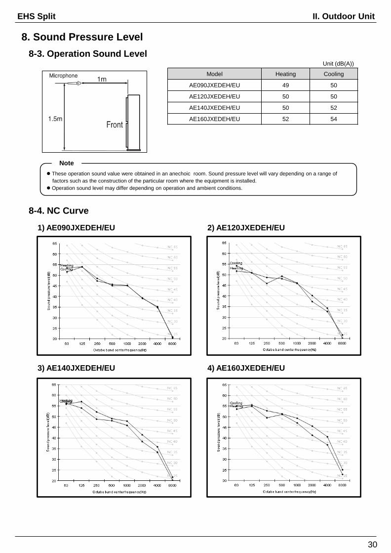
8. Sound Pressure Level
Model Heating Cooling
AE090JXEDEH/EU 49 50
AE120JXEDEH/EU 50 50
AE140JXEDEH/EU 50 52
AE160JXEDEH/EU 52 54
Unit (dB(A))
8-3. Operation Sound Level
These operation sound value were obtained in an anechoic room. Sound pressure level will vary depending on a range of
factors such as the construction of the particular room where the equipment is installed.
Operation sound level may differ depending on operation and ambient conditions.
Note
8-4. NC Curve
1) AE090JXEDEH/EU 2) AE120JXEDEH/EU
3) AE140JXEDEH/EU 4) AE160JXEDEH/EU
30

II. Outdoor UnitEHS Split
8. Sound Pressure Level
Model Heating Cooling
AE090JXEDGH/EU 49 50
AE120JXEDGH/EU 50 50
AE140JXEDGH/EU 50 52
AE160JXEDGH/EU 52 54
Unit (dB(A))
8-5. Operation Sound Level
These operation sound value were obtained in an anechoic room. Sound pressure level will vary depending on a range of
factors such as the construction of the particular room where the equipment is installed.
Operation sound level may differ depending on operation and ambient conditions.
Note
8-6. NC Curve
1) AE090JXEDGH/EU 2) AE120JXEDGH/EU
3) AE140JXEDGH/EU 4) AE160JXEDGH/EU
31

II. Outdoor UnitEHS Split
9. Operation Range
32
35
-10
-25
15 20 37 55
Leaving water temp. (℃)O
utd
oor
tem
p. (℃
, D
B)
46
10
5 25
Leaving water temp. (℃)
Outd
oor
tem
p. (℃
, D
B)
Backup heater operation
& No guarantee of capacity
9-1. Outdoor Unit
1) Cooling 2) Heating
MONO Outdoor UnitWater Temp. (℃) Water Flow Rates (LPM) Air Temp. (℃, DB/WB)
Min Std Max Min Std Max Min Std Max
ControllerCooling 5 - 25
Heating 15 - 55
CoolingInlet - 23 (12*2) 30
12 (7*1) Δ 5℃ 58 (48*1)
10/- 35/24 46/28Outlet 5 18 (7*2) 25
HeatingInlet 5 30 (40*2) -
-25/-7/6
(-7/-8*3)35/24
Outlet 25 (15*4) 35 (45*2) 55
*1) Model : AE040JXEDEH/AE090JNYDEH
AE060JXEDEH/AE090JNYDEH
AE090JXEDEH/AE090JNYDEH
AE090JXEDGH/AE090JNYDEH
*2) Eurovent Test Condition #2
*3) NF PAC Low Temp. Heating Condition.
*4) Back up heater operation.
※ Operation of outdoor unit possible, but no guarantee of capacity in this condition. ( -25℃ ≤ Outdoor temp <-20℃)
-20
25
24
43
3) DHW (Domestic Hot Water Tank)
Outd
oor
Te
mp. ( ℃
DB
)
35
Leaving water temp. (℃)
--25
Booster heater
operation only
43
※ Special condition( 35℃ < Outdoor temp. ≤ 43℃) is operated by only Booster Heater.
SAMSUNG doesn’t supply DHW for EHS Split.
Since it is a reference data, you have to check DHW operation range for yours.

III. Hydro Unit
1. Specifications ……..………..…...……….…..…..……… 34
2. Dimensional Drawings ………...………..………………. 36
3. Cycle Diagrams …………………………………………. 37
4. Wiring Diagrams ……………...…..……..………………. 38
5. Electric Specifications ………….……….……………… 40
6. Hydraulic Performance …….…………….……………… 43

III. Hydro UnitEHS Split
34
1. Specifications
1-1. Hydro Unit (1Ф)
Model Name Indoor Unit AE090JNYDEH/EU AE160JNYDEH/EU
Hydro Unit
Power Supply Φ, #, V, Hz 220~240V, 50Hz, 1Ф 220~240V, 50Hz, 1Ф
Water
Pump
Type (Model Name) -Centrifurugal
(UPM3 25-7.5)
Centrifurugal
(Stratos 25 1-9)
Motor Input W 60 90
Number of Unit EA 1 1
Flow SwitchType (Model Name) - Magnetic, Decreasing Magnetic, Decreasing
Min. flow rates LPM 7 ± 1.5 12 ± 1.5
Electric Heater W 4,000 6,000
Expansion Vessel Liter 8 8
Pressure Relief Valve bar 2.9 2.9
Air Purge Valve Ф, inch BSPP male 3/8" BSPP male 3/8"
Service Valve Ф, inch BSPP male 1 1/4" BSPP male 1 1/4"
Sound *1
Sound
Pressure
Heating Std dB(A) 26 33
Cooling Std dB(A) 26 33
Sound
PowerHeating Std dB(A) 40 47
External
Dimension
Net Weight kg 45.0 45.0
Shipping Weight kg 55.0 55.0
Net Dimensions (WxHxD) mm 510 x 850 x 315 510 x 850 x 315
Shipping Dimensions
(WxHxD)mm 564 x 1,024 x 426 564 x 1,024 x 426
External
Control
Back up Boiler - 230VAC 0.5A(DO) 230VAC 0.5A(DO)
Room Thermostat - 230VAC 10mA(DI) 230VAC 10mA(DI)
Solar Pump - 230VAC 10mA(DI) 230VAC 10mA(DI)
Valves, 2 or 3way - 230VAC 0.5A(DO) 230VAC 0.5A(DO)
*1) Sound level was acquired in an anechoic room. Thus actual noise level may be different depending on the installation conditions.

III. Hydro UnitEHS Split
1. Specifications
1-2. Hydro Unit (3Ф)
Model Name Indoor Unit AE090JNYDGH/EU AE160JNYDGH/EU
Hydro Unit
Power Supply Φ, #, V, Hz 380~4150V, 50Hz, 3Ф 380~4150V, 50Hz, 3Ф
Water
Pump
Type (Model Name) -Centrifurugal
(UPM3 25-7.5)
Centrifurugal
(Stratos 25 1-9)
Motor Input W 60 90
Number of Unit EA 1 1
Flow SwitchType (Model Name) - Magnetic, Decreasing Magnetic, Decreasing
Min. flow rates LPM 7 ± 1.5 12 ± 1.5
Electric Heater W 6,000 6,000
Expansion Vessel Liter 8 8
Pressure Relief Valve bar 2.9 2.9
Air Purge Valve Ф, inch BSPP male 3/8" BSPP male 3/8"
Service Valve Ф, inch BSPP male 1 1/4" BSPP male 1 1/4"
Sound *1
Sound
Pressure
Heating Std dB(A) 26 33
Cooling Std dB(A) 26 33
Sound
PowerHeating Std dB(A) 40 47
External
Dimension
Net Weight kg 46.5 46.5
Shipping Weight kg 56.0 56.0
Net Dimensions (WxHxD) mm 510 x 850 x 315 510 x 850 x 315
Shipping Dimensions
(WxHxD)mm 564 x 1,024 x 426 564 x 1,024 x 426
External
Control
Back up Boiler - 230VAC 0.5A(DO) 230VAC 0.5A(DO)
Room Thermostat - 230VAC 10mA(DI) 230VAC 10mA(DI)
Solar Pump - 230VAC 10mA(DI) 230VAC 10mA(DI)
Valves, 2 or 3way - 230VAC 0.5A(DO) 230VAC 0.5A(DO)
35
*1) Sound level was acquired in an anechoic room. Thus actual noise level may be different depending on the installation conditions.

III. Hydro UnitEHS Split
36
2. Dimensional Drawings
2-1. Hydro Unit
1) AE090/160JNYD*H/EU(Unit : mm)
①②
③
④
No. Table of Descriptions
① Gas Ref. Pipe
② Liquid Ref. Pipe
③ Water Pipe (Inlet/Outlet)
④ Drain Hose Connector
IN OUT

III. Hydro UnitEHS Split
3-1. Hydro Unit
1) AE090/160JNYD*H/EU
37
3. Cycle Diagrams
No. Description
① Water Pipe Service Valve (R)
② Strainer
③ Flow Switch
④ Heat Changer
⑤ Backup Heater
⑥ Pressure Relief Valve
⑦ Air-vent
⑧ Variable Speed water pump
⑨ Expansion Tank
⑩ Manometer
No. Description
⑪ Water Pipe Service Valve (L)
⑫ Water Temp. Sensor 1
⑬ Water Temp. Sensor 2
⑭ Water Temp. Sensor 3
III. Hydro UnitEHS Split
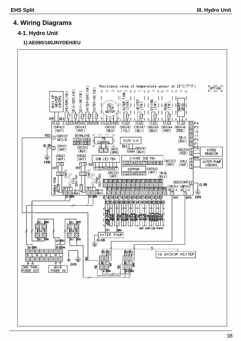
38
4. Wiring Diagrams
4-1. Hydro Unit
1) AE090/160JNYDEH/EU
III. Hydro UnitEHS Split
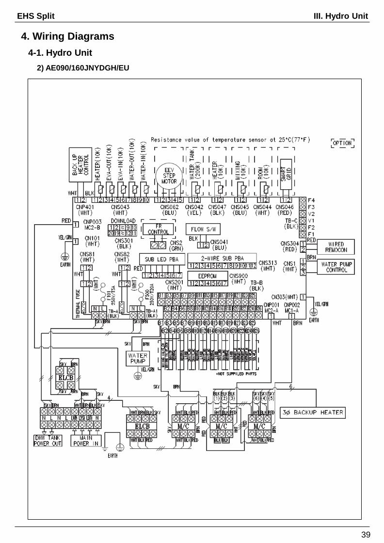
39
4. Wiring Diagrams
4-1. Hydro Unit
2) AE090/160JNYDGH/EU

III. Hydro UnitEHS Split
5. Electric Specifications
5-1. Hydro Unit
1) Power supply & Communication
2) Back-up Heater Power supply
40

III. Hydro UnitEHS Split
5. Electric Specifications
41
5-1. Hydro Unit
3) Thermostat
4) 2way Valve

III. Hydro UnitEHS Split
5. Electric Specifications
42
5-1. Hydro Unit
5) 3way Valve
5) Back-up Boiler
6) Mixing Valve

III. Hydro UnitEHS Split
6. Hydraulic Performance
43
6-1. Water Pump
The illustration below shows the external static pressure of the unit depending on the water flow and the pump setting.
If the pressure loss of total system is over 43(9 kW) or 20(16 kW)kPa, additional water pump should be installed in series.
Otherwise, the flow rate might decreased, causing insufficient heating or cooling.
When ESP is not enough, additional pump should be installed. In this case, install the PWM control external type pump additionally.
1) ESP(External Static Pressure) Diagram
6-2. Expansion Vessel
1) Setting the pre-pressure of the expansion vessel
When it is required to change the default pre-pressure of the expansion vessel(1 bar), keep in mind the following guidelines
◆ Use only dry nitrogen to set the expansion vessel pre-pressure.
◆ Inappropriate setting of the expansion vessel pre-pressure will lead to malfunction of the system. Therefore, the pre-pressure
should only be adjusted by a licensed installer.

III. Application
1. Application Examples ……...…………..…..…..……… 45
2. Mixing Valve ………..…...…………..…..…..……… 47

III. Hydro UnitEHS Split
45
1. Application Examples
1-1. Space Heating
1-2. Space Heating + Water Heating

III. Hydro UnitEHS Split
46
1. Application Examples
1-3. Hybrid Application (Back-up Boiler & Solar Panel connected)

III. Hydro UnitEHS Split
47
2. Mixing Valve
1-1. Mixing Valve Installation
1-2. Connection Of Mixing Valve