Embed Size (px)
Citation preview
Research
History of Accelerated and QualificationTesting of Terrestrial PhotovoltaicModules: A Literature ReviewC. R. Osterwald*,y and T. J. McMahonNational Renewable Energy Laboratory, Golden, CO, USA
We review published literature from 1975 to the present for accelerated stress testing of flat-plate terrestrial
photovoltaic (PV) modules. An important facet of this subject is the standard module test sequences that have
been adopted by national and international standards organizations, especially those of the International
Electrotechnical Commission (IEC). The intent and history of these qualification tests, provided in this
review, shows that standard module qualification test results cannot be used to obtain or infer a product
lifetime. Closely related subjects also discussed include: other limitations of qualification testing, definitions
of module lifetime, module product certification, and accelerated life testing. Copyright# 2008 JohnWiley &
Sons, Ltd.
key words: photovoltaics; module; terrestrial; testing; accelerated; qualification; lifetime
Received 5 May 2008; Revised 26 August 2008
INTRODUCTION
From the early days of photovoltaics (PV) following
the invention of the silicon solar cell at Bell
Laboratories1 and since silicon solar cells were first
soldered together into series strings to produce power
from sunlight,2 two key questions have been: how long
will these string assemblies, now called modules,
deliver useful power? And can accelerated testing can
provide this information? Over the past 30-plus years,
much research and testing has been done on PV
reliability by government laboratories, third-party
laboratories, and PV manufacturers. This work has
resulted in the development of standardized module
testing sequences commonly called qualification or
type-approval tests. These sequences are relatively
short in duration, about 3–4 months, and include tests
such as accelerated temperature and humidity stresses
inside climatic environmental chambers. Adoption of
the sequences as national and international standards
has led to their widespread use as the final hurdle in
product development.
In 2006, electrical arcing and fires inside module
junction boxes caused failures in a number of PV
systems; these failures were reported in the trade
magazine PHOTON International.3 The modules in
question were produced by a reputable PV manufac-
turer with over 30 years of experience, and had passed
all of the standard qualification and safety tests.
Later reports indicated that the problem was not
restricted to this manufacturer.4 An obvious question
is then: how could these failures have occurred after
all of this careful design and testing? Subsequent
investigations appeared to indicate the arcing was
PROGRESS IN PHOTOVOLTAICS: RESEARCH AND APPLICATIONS
Prog. Photovolt: Res. Appl. 2009; 17:11–33
Published online 7 October 2008 in Wiley InterScience (www.interscience.wiley.com) DOI: 10.1002/pip.861
*Correspondence to: C. R. Osterwald, National Renewable EnergyLaboratory, Golden, CO, USA.yE-mail: [email protected]
Copyright # 2008 John Wiley & Sons, Ltd.
the result of an inadequate manual soldering step
during manufacturing. Because the flaw was unknown
prior to the occurrences of the junction-box fires,
the qualification tests were not designed to test for
susceptibility to the problem. Therefore, these stan-
dard tests cannot be expected to catch all module
problems.
The objective of this paper is to document how
these qualification tests have evolved over time by
presenting a roughly chronological literature review,
and thereby showing that the individual elements are
designed to stress modules in ways that uncover
susceptibility to known failure mechanisms. The
review will also include the numerous accelerated
tests that have been applied to PV modules. To
these ends, it will be helpful to first discuss some
major terms that are commonly used and associated
with PV.
Although the history attempts to summarize major
points and conclusions, it cannot be a substitute for
reading and studying the reviewed publications. With
more than 170 references here, much information has
been omitted of necessity.
Qualification testing of concentrator modules is
a complex subject with very different issues and
was therefore judged to be beyond the scope of this
review.
Modules
A PV module can be defined as a collection of
individual solar cells integrated into a package that
protects them from the environment in which the
module is installed for a long period of time. Modules
must be manufactured as inexpensively as possible
because their price is a significant portion of the cost of
electricity generated by a system, yet they must be
capable of operating in many climates such as
maritime tropical, high-temperature, high-irradiance
deserts, and dirty urban rooftops. The solar cells must
be protected from degradation caused by stresses and
effects such as:
� Corrosion of materials, especially metals
� Water-vapor intrusion
� Delamination of encapsulant materials, especially
polymers
� Physical damage from wind, hail, and installa-
tion
� Thermal excursions, including coefficient of ther-
mal expansion mismatches
� Ultraviolet (UV) radiation
� Deterioration of or damage to external components
such as junction boxes, wiring, and frames.
Because of the imperative to minimize module cost,
the degree of protection from these effects must
necessarily be imperfect, and a design trade-off
between cost and protection exists. Typically, the
costs of the materials used for protecting the internal
solar calls (packaging costs) are roughly 50% of the
total materials cost.
Module designs continue to evolve and change,
which presents continuing challenges to testing
procedures. Crystalline-Si (x-Si) cells are becoming
thinner and thinner, new thin-film devices with exotic
materials are being developed, and building-inte-
grated PV (BIPV) is challenging ideas about what
constitutes a module.5 Devising adequate qualifica-
tion tests that may be needed to stress new failure
mechanisms in these products requires on-going
research with real-time outdoor testing to discover
the mechanisms, and indoor accelerated testing to
simulate them.
Qualification testing
Since the late 1970s, there have been a number of PV
qualification test sequences, first published by govern-
ment laboratories and then later by national and
international standards organizations, intended to
gauge the ability of module designs to protect solar
cells from the environment. Each in succession has
built on previous tests as new information is learned,
and the older tests are made obsolete. As the PV
industry has grown and become an international
commodity market, the International Electrotechnical
Commission (IEC) test standards6 are now the only
tests accepted by both module manufacturers and
buyers.
Hoffman and Ross7 defined the purpose of
qualification testing as being a means of rapidly
detecting the presence of known failure or degra-
dation modes in the intended environment(s). It also
provides ‘‘rapid feedback of the relative strengths
and acceptabilities of design alternatives’’ during
product development.
The test sequences are relatively short in duration,
a few months, and are separated into several ‘‘legs’’
performed on different modules that can be done in
parallel. At the end of the sequences, test modules
must retain a specified percentage of their initial
output power in order to be judged as having passed
the qualification. Figure 1 shows an example of a
Copyright # 2008 John Wiley & Sons, Ltd. Prog. Photovolt: Res. Appl. 2009; 17:11–33
DOI: 10.1002/pip
12 C. R. OSTERWALD AND T. J. MCMAHON
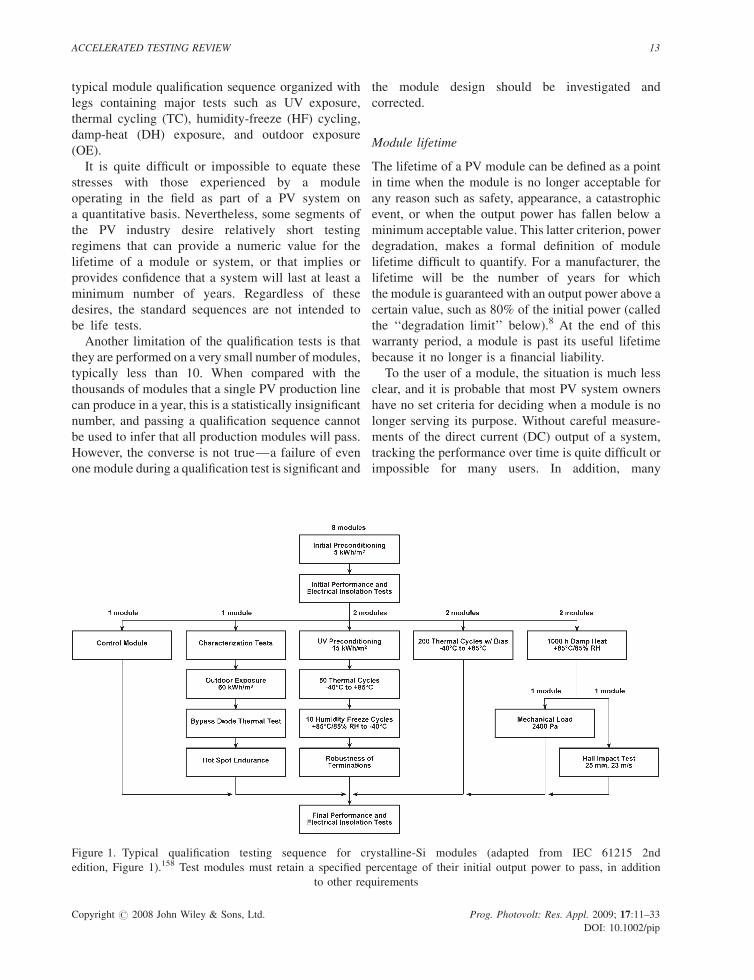
typical module qualification sequence organized with
legs containing major tests such as UV exposure,
thermal cycling (TC), humidity-freeze (HF) cycling,
damp-heat (DH) exposure, and outdoor exposure
(OE).
It is quite difficult or impossible to equate these
stresses with those experienced by a module
operating in the field as part of a PV system on
a quantitative basis. Nevertheless, some segments of
the PV industry desire relatively short testing
regimens that can provide a numeric value for the
lifetime of a module or system, or that implies or
provides confidence that a system will last at least a
minimum number of years. Regardless of these
desires, the standard sequences are not intended to
be life tests.
Another limitation of the qualification tests is that
they are performed on a very small number of modules,
typically less than 10. When compared with the
thousands of modules that a single PV production line
can produce in a year, this is a statistically insignificant
number, and passing a qualification sequence cannot
be used to infer that all production modules will pass.
However, the converse is not true—a failure of even
one module during a qualification test is significant and
the module design should be investigated and
corrected.
Module lifetime
The lifetime of a PV module can be defined as a point
in time when the module is no longer acceptable for
any reason such as safety, appearance, a catastrophic
event, or when the output power has fallen below a
minimum acceptable value. This latter criterion, power
degradation, makes a formal definition of module
lifetime difficult to quantify. For a manufacturer, the
lifetime will be the number of years for which
the module is guaranteed with an output power above a
certain value, such as 80% of the initial power (called
the ‘‘degradation limit’’ below).8 At the end of this
warranty period, a module is past its useful lifetime
because it no longer is a financial liability.
To the user of a module, the situation is much less
clear, and it is probable that most PV system owners
have no set criteria for deciding when a module is no
longer serving its purpose. Without careful measure-
ments of the direct current (DC) output of a system,
tracking the performance over time is quite difficult or
impossible for many users. In addition, many
Figure 1. Typical qualification testing sequence for crystalline-Si modules (adapted from IEC 61215 2nd
edition, Figure 1).158 Test modules must retain a specified percentage of their initial output power to pass, in addition
to other requirements
Copyright # 2008 John Wiley & Sons, Ltd. Prog. Photovolt: Res. Appl. 2009; 17:11–33
DOI: 10.1002/pip
ACCELERATED TESTING REVIEW 13
applications may have criteria for usability that are
very different from the manufacturer’s warranty.
Important issues with module lifetime are discussed
by McMahon et al.,9 who believed that it is impossible
to provide a 30-year lifetime certification for any given
module based on a single test. While presenting the
conflicting viewpoints of manufacturers and users,
Schlumberger10 wrote in PHOTON International that
‘‘. . .experts can’t even agree on what constitutes the
end of a module’s product life.’’ Note that it is
impossible to state what the lifetime of a module is
without a formal definition of the end-of-life.
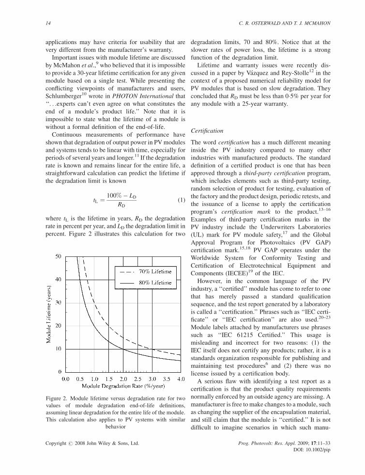
Continuous measurements of performance have
shown that degradation of output power in PVmodules
and systems tends to be linear with time, especially for
periods of several years and longer.11 If the degradation
rate is known and remains linear for the entire life, a
straightforward calculation can predict the lifetime if
the degradation limit is known
tL ¼ 100%� LD
RD
(1)
where tL is the lifetime in years, RD the degradation
rate in percent per year, and LD the degradation limit in
percent. Figure 2 illustrates this calculation for two
degradation limits, 70 and 80%. Notice that at the
slower rates of power loss, the lifetime is a strong
function of the degradation limit.
Lifetime and warranty issues were recently dis-
cussed in a paper by Vazquez and Rey-Stolle12 in the
context of a proposed numerical reliability model for
PV modules that is based on slow degradation. They
concluded that RD must be less than 0�5% per year for
any module with a 25-year warranty.
Certification
The word certification has a much different meaning
inside the PV industry compared to many other
industries with manufactured products. The standard
definition of a certified product is one that has been
approved through a third-party certification program,
which includes elements such as third-party testing,
random selection of product for testing, evaluation of
the factory and the product design, periodic retests, and
the issuance of a license to apply the certification
program’s certification mark to the product.13–16
Examples of third-party certification marks in the
PV industry include the Underwriters Laboratories
(UL) mark for PV module safety,17 and the Global
Approval Program for Photovoltaics (PV GAP)
certification mark.15,18 PV GAP operates under the
Worldwide System for Conformity Testing and
Certification of Electrotechnical Equipment and
Components (IECEE)19 of the IEC.
However, in the common language of the PV
industry, a ‘‘certified’’ module has come to refer to one
that has merely passed a standard qualification
sequence, and the test report generated by a laboratory
is called a ‘‘certification.’’ Phrases such as ‘‘IEC certi-
ficate’’ or ‘‘IEC certification’’ are also used.20–23
Module labels attached by manufacturers use phrases
such as ‘‘IEC 61215 Certified.’’ This usage is
misleading and incorrect for two reasons: (1) the
IEC itself does not certify any products; rather, it is a
standards organization responsible for publishing and
maintaining test procedures6 and (2) there was no
license issued by a certification body.
A serious flaw with identifying a test report as a
certification is that the product quality requirements
normally enforced by an outside agency are missing. A
manufacturer is free to make changes to a module, such
as changing the supplier of the encapsulation material,
and still claim that the module is ‘‘certified.’’ It is not
difficult to imagine scenarios in which such manu-
Figure 2. Module lifetime versus degradation rate for two
values of module degradation end-of-life definitions,
assuming linear degradation for the entire life of the module.
This calculation also applies to PV systems with similar
behavior
Copyright # 2008 John Wiley & Sons, Ltd. Prog. Photovolt: Res. Appl. 2009; 17:11–33
DOI: 10.1002/pip
14 C. R. OSTERWALD AND T. J. MCMAHON
facturing changes could adversely affect the lifetime of
a PV module.
Accelerated life testing
One example of an accelerated life test is to apply stress
to a test sample until failure.24,25 Note the difference
here from that of qualification testing, which applies
stress for only a prescribed and limited duration.
Hoffman andRoss emphasized that, unlike qualification
tests, reliability and life-prediction tests must be
designed ‘‘to provide quantitative information on
mean-time-between-failures [MTBFs] or lifetimes.’’7
In a tutorial on PV qualification testing, Wohlgemuth26
reiterated this distinction by stating that ‘‘qualification
testing does not provide a prediction of product
lifetime.’’
For PV, there are only a limited number of use and
stress factors that can be accelerated, namely:
illumination duty cycle, total irradiance, UV irradi-
ance, temperature, humidity, or combinations of these
factors. However, applying stresses to modules that
result in temperatures higher than about 908C can
result in damage to materials that may never occur in
actual use, and temperature cannot easily be used as an
acceleration factor for thin-film devices because output
power can increase and decrease as a result of previous
thermal and illumination states. PV acceleration
factors for temperature and humidity have proven to
be quite unwieldy to determine, and little is published
on the subject (the Jet Propulsion Laboratory [JPL]
work in this area will be outlined below). For
accelerated UV irradiance, if the applied UV spectral
irradiance contains significant numbers of high-energy
photons that are not present in terrestrial sunlight,
unrelated damage may be induced.
One practical accelerated life test for PV could be
continuous light-soaking (100% duty cycle) without
elevated irradiance (continuous light-soaking has been
used extensively for a-Si initial light-induced degra-
dation determinations).27,28 Such a test can be directly
correlated with real-time exposure using the average
daily irradiance profiles from a target site; this results
in acceleration factors in the range of 3� to 5�,
depending on the geographical location.
Another approach is to use the standard qualification
stress tests, but extend them until failure of the test
modules, known as test-to-failure (TTF). BP Solar has
employed this technique as part of an overall module
reliability program, primarily with TC.25 Such tests
can provide qualitative information about ultimate
failure modes, but do not provide numeric lifetime
data.
MODULE QUALIFICATION ANDACCELERATED TESTING: HISTORYAND LITERATURE REVIEW
The review is approximately chronological, and is
divided into sections 5 years in length. Year 1975 was
selected as the starting point of the history, even though
module technology began at Bell Laboratories in the
mid-1950s. Prior to 1975, the literature is nearly silent
on module stress testing, and terrestrial modules were
low power (Green authored a review in 2005 that
documents the history of x-Si module technology).2
Publications on related subjects such as cell lifetime or
materials testing are included, especially if they have a
bearing on the development of the standard tests.
As will be seen, two bodies of work are especially
important. The first is the Flat-Plate Solar Array
Project (FSA) at JPL (the program had several titles,
including the Low-Cost Silicon Solar Array Project,
the Low-Cost Solar Array Project, as well as the FSA
Project). The second is that of the Joint Research
Center (JRC) of the European Commission, Ispra, Italy
(also known as the European Solar Test Installation,
ESTI); JRC has been very active in both developing
and applying the standard qualification sequences. The
Solar Energy Research Institute (SERI, later the
National Renewable Energy Laboratory, NREL) held
a series of workshops over the 1985–1999 period on
PV performance and reliability where advancements in
module testing were presented.
One element of module qualification are the hot-spot
(HS) endurance tests, which are intended to determine
if a module design is protected from excessive and
destructive heating caused by cells forced to dissipate
power in reverse bias. Although the tests are docu-
mented here, they are too complex to be described in
any detail.
A potential source of confusion about the IEC
standards is that in 1997 the number 60 000 was added
to all the designation numbers. Thus, IEC 1215 became
IEC 61215, although the two designations refer to the
same document.
Finally, a shorthand notation for temperature–
humidity conditions is used: 85/65 DH indicates a
stress level of 858C module temperature and 65%
relative humidity.
Copyright # 2008 John Wiley & Sons, Ltd. Prog. Photovolt: Res. Appl. 2009; 17:11–33
DOI: 10.1002/pip
ACCELERATED TESTING REVIEW 15
1975–1979
Serious development of terrestrial PV modules in the
United States began in the mid-1970s under the
sponsorship of the US Energy Research and Devel-
opment Agency (ERDA),29 which later became a part
of the US Department of Energy (DOE). Because of its
experience with spacecraft PV power systems, the
National Aeronautics and Space Administration
(NASA) had key roles through two of its laboratories:
JPL in Pasadena, California, and the Lewis Research
Center (LeRC) in Cleveland, Ohio.30 JPL had
responsibility for the FSA project.31,32 LeRC devel-
oped the first terrestrial PV performance measurement
techniques and operated an OE program at a number of
sites.33
The FSA project was organized as a series of
purchases of PV modules from manufacturers,
designated as Block I through Block V (Block VI
was planned, but not executed).31,34 To qualify for one
of the block procurements, manufacturers had to build
modules that met the specification document, includ-
ing a series of prescribed tests. Thus, the JPL
specifications were the first qualification tests imple-
mented for terrestrial PV. Purchased modules were
transferred to LeRC, the Massachusetts Institute of
Technology’s Lincoln Laboratory, Wyle Laboratories
(Huntsville, Alabama), and Clemson University for
further testing with real-time OE35 and parametric
temperature–humidity testing.36 A highlight of the
FSA project was the development of ethylene vinyl
acetate (EVA) as a replacement for silicones and
polyvinyl butyral (PVB) encapsulants.31,37–39
The qualification test elements used in the FSA
project changed considerably over Blocks I–V;7,34
these elements included temperature cycling, humidity
cycling, cyclic pressure loading, warped mounting
surface (later called the twist test), hot spot endurance,
hail impact, and electrical isolation. The testing for
Block I consisted of just 100 thermal cycles and 7 days
of humidity stress (70/90 DH).
The Hoffman and Ross article discussed how the
upper and lower temperature limits (þ908C and
�408C), thermal ramp rate limit (1008C/h maximum),
and number of cycles were selected.7 The purpose of
TC was to represent stress due to diurnal and climatic
temperature excursions.
The humidity test used with the early procurements
(II, III) changed from the short 70/90 DH exposure test
in Block I to a cyclic test selected from existing
military and space test specifications, and consisted of
five 1-day cycles from þ23 to þ40�58C cell
temperature at 90–95% RH. Humidity testing was
used to eliminate metal delamination of Ag–Ti
contacts in space solar cells.7
All of the tests were performed sequentially; thus,
the tests effectively consisted of only one leg as defined
in the ‘‘Qualification Testing’’ section above. The
complete qualification tests for Blocks II and III and
development of the cyclic-load test were documented
in several JPL internal reports.40–42 Block IV was
initiated in 1978.31
Using feedback from outdoor testing, Hoffman and
Ross identified several degradation modes, and
described some exploratory tests intended to replicate
them: soiling, encapsulant delamination, ion migra-
tion, and galvanic corrosion.7 Migration and corrosion
were observed with voltage-biased humidity exposure,
although these were of a different nature from that seen
in modules exposed outdoors. Voltage bias detected
problems that were not detected by other tests, and JPL
wanted to add this requirement to Block VI.
Two JPL papers at the 1978 Washington, DC, IEEE
PV Specialists Conference discussed possible and
observed module failure modes, and analysis tech-
niques used to study these problems.43,44 Failures
noted included open cell interconnects, cracked cells,
delamination, dielectric breakdown, and corrosion. A
subsequent 1981 JPL paper presented a summary of
the field test results from Blocks I–III.45 The failures
listed were similar and included some specific
observations of corrosion.
1980–1984
An early JRC paper in 1980 outlined the two tasks
assigned to the Ispra Establishment, namely develop-
ment of performance measurements on solar cells and
modules and qualification testing of modules.46 These
procedures were developed through a European
Working Group on PV Testing, and the qualification
test procedures were called CEC Specification No.
201. This document was indicated as being a ‘‘final
version in preparation,’’ although few details of the
testing sequence were provided. A one-paragraph
outline listed the tests contained in CEC 201, which
were:
� Hail impact
� UV exposure
� Wind pressure
� Temperature cycling: �40 to þ858C
Copyright # 2008 John Wiley & Sons, Ltd. Prog. Photovolt: Res. Appl. 2009; 17:11–33
DOI: 10.1002/pip
16 C. R. OSTERWALD AND T. J. MCMAHON
� ‘‘Smog’’
� Humidity cycling: 20/10 DH–40/100 DH
� Thermal degradation, including shocks with cold-
water spray.
A presentation at the 1980 EC conference in Cannes,
France, by Desombre outlined a reliability study on PV
modules and tried to show how lifetimes might be
determined from acceleration factors of failure
mechanisms.47 Two models were discussed; the first
was the Arrhenius relationship of absolute temperature
and an activation energy. The second was an empirical
function of the sum of two terms, the temperature in 8Cand the relative humidity in percent. A graph showed
‘‘time to contact corrosion’’ using this empirical
function, but it is not clear from the text if the points on
the graph were experimental data or not. Two test
conditions were indicated on the graph: 55/95 DH and
85/85 DH. Later, the Desombre empirical temperature-
plus-humidity acceleration model was used in the JPL
corrosion model (see below).
The specifications and testing requirements for the
last FSA procurement, Block V, were published in
1981 and became the de facto standard for module
quality48 and module safety49,50 in the United States.
The term ‘‘passed Block V’’ was commonly used to
indicate that a module design had been subjected to
and passed the JPL tests.
The Block V test sequence contained two legs: one
with 200 thermal cycles, and the other required 50
thermal cycles, 10 HF cycles, 10 000 dynamic load
cycles,42 the twist test, and the hail impact test. Along
with the longer TC leg, the Block V specification
changed the temperature limits of the former
‘‘humidity’’ test in earlier specifications to the �40
to þ858C HF cycling test. Module performance
degradation that resulted from the testing could not
exceed 5%, and the specification included require-
ments for visual changes and electrical isolation. The
leakage current during a 1-min electrical isolation
(‘‘hi-pot’’) test at �3000V between the shorted leads
and the module grounding point could not exceed
50mA. Qualification test results from Block V were
published in 1982,51 and an overview of the module
development and test results were published in 1985.52
A HS endurance test that was included in the
Block V specification was documented in a 1981
paper.53 The complicated 100-h cyclic procedure
consisted of selecting a number of individual cells
based on their reverse bias I–V characteristics to be
subjected to heating from infrared illumination, visible
illumination, and a voltage bias.
Under subcontract to JPL, UL developed a
recommendation for a module safety standard that
was published in two parts, and was used for the
Block V purchases.49,50 The JPL interim safety standard
was the first to use the 2� VS þ 1000 dielectric voltage
withstand test level specification, where VS is the
module maximum system voltage rating.
Year 1981 also saw the publication of the first
European qualification test sequence, CEC Specifica-
tion 501.54 These tests were quite different from those
indicated earlier for CEC 201.46 CEC 501 used a twist
test, nominal operating cell temperature (NOCT)
determination, and hail test very similar to the JPL
tests, and included several figures from the Block V
specification. It also had a degradation limit require-
ment of 5%. Other tests included:
� Temperature cycling: –40 to +408C+NOCT, 50
cycles
� Humidity-freezing: 40/93 DH for 48 h, then –408Cfor 1 h, 1 cycle
� Mechanical load: 2400 Pa, and an optional 5400 Pa
test for wind and snow
� DH long exposure: 40/93 DH, 720 h
� High-temperature long exposure: NOCT+ 508C,2880 h
� UV exposure: NOCT+ 308C, 40MJ/m2
� Ozone test: 408C, 55% RH, 120 h, 0�5 vpm O3
� SO2 test: 258C, 75% RH, 120 h, 50 ppm SO2
� Salt mist: 358C, 96 h, 50 g NaCl/L
� Ice formation: +20 to –108C with a water spray,
60min
� HS heating: complex 1-h cyclic test repeated 50�.
Krebs published some experiences and results of
applying the CEC 501 test in 1982,55 and a subsequent
1983 paper56 briefly reported results of the same tests,
and stated that the test sequence had been modified as a
consequence of testing experience. The new sequence
had a block called ‘‘Temperature & Humidity
Storage,’’ and did not use the term damp heat. This
terminology was included in the updated European
qualification sequence, CEC 502, which was published
the next year,57 although the sequence in CEC 502
differed greatly from the JRC paper, and from CEC
501. An OE test was described for the first time,
‘‘outdoor pre-conditioning,’’ and the atmospheric
pollution-related tests were dropped, along with the
40/93 DH test. The ‘‘high-temperature storage’’ test
Copyright # 2008 John Wiley & Sons, Ltd. Prog. Photovolt: Res. Appl. 2009; 17:11–33
DOI: 10.1002/pip
ACCELERATED TESTING REVIEW 17
consisted of 908C for 20 days, while the ‘‘high-
temperature/high-humidity’’ test required 20 days at
90/95 DH. The TC test in CEC 502 specified 10 cycles
between –20 and +808C. CEC 502 included a 1-h HS
endurance test that was much simpler than the JPL
test.53 One cell was selected with infrared imaging
while the test module was shorted and in 1-sun
illumination; this cell was shadowed for 1 h.
The IEC established Technical Committee 82
(TC82) on Solar Photovoltaic Energy Systems in
1981, and gave oversight for international module-
related standards to Working Group 2 (WG2), which
included future module qualification standards.58
Treble noted that such standards had to be an
evolutionary process with improvements incorporated
as experience is accumulated.
Ross published several considerations of predicting
reliability or assuring lifetime of modules in this
period.59–61 A review of module degradation mech-
anisms concluded that a lack of known wearout
mechanisms implies that module lifetimes in excess of
25 years is likely.60 This paper mentioned that 85/85
DH is commonly used in the semiconductor industry
and the PV cell-reliability testing at Clemson
University. A description of the Clemson test program
indicated that encapsulated cells were exposed to 85/
85 DH and –40 to +1008C thermal cycles.62
The US Coast Guard developed a qualification test
for modules intended to power offshore navigation
aids.63 The qualification consists of a pressure-
immersion-temperature (PIT) cyclic test that simulates
an environment where a module operating in full
sunlight is quickly immersed to a depth of several
meters in seawater as a result of wave action. The
authors estimated the acceleration factor of the PIT test
at 45:1.
Using the Desombre empirical acceleration model
for temperature and humidity,47 module indoor stress
testing at several levels, and hourly weather data for the
United States, Otth and Ross at JPL attempted to
equate hours of damp heat testing with a 20-year
module life at site-specific conditions,64 and estimated
20 years exposure in Miami, Florida, is correlated with
144 h at 85/85 DH. This correlation was for just a
single failure mechanism: galvanic or electrolytic
corrosion of x-Si cells and metallization driven by
the resistivity of polymeric encapsulants. An inte-
resting aspect of this work was the use of color
density measurements on photographs of stressed
modules to determine degradation rates of the
polymers.36
JPL published another study of electrochemical
corrosion and metal migration in x-Si cells and
modules in 1984 that included life predictions based on
total charge transfer and hourly US weather data.65 The
paper ended with a discussion of water-vapor intrusion
into modules with PVB and EVA encapsulants.
Electrochemical degradation of a-Si modules was
later performed with 85/85 DH exposure and a�500V
bias between the frame and module leads while
measuring leakage currents.66 This accelerated test
was able to duplicate corrosion and damage effects on
a-Si modules that had been observed outdoors. An
adjunct paper reported how temperature and humidity
affects these leakage currents and included relevant
data for PVB and EVA.67
1985–1989
In a review of the JPL Block programs, Smokler stated
that several new qualification tests were proposed for
the never-implemented Block VI program, including a
UV exposure test, a bypass diode thermal test, and an
electrochemical stress test at 85/85 DH and �500V.31
Another JPL paper by Ross gave a review of the
reliability testing lessons from the FSA project, and
made recommendations for applying these to thin-film
modules using qualification and laboratory stress
testing, OE testing at both the module and system
levels, and failure analyses.68
The first comprehensive safety standard for PV
modules was published in 1986 by Underwriters
Laboratories, UL 1703, and became the basis for UL’s
module listing and labeling program for safety in the
United States.17,69 The important difference between a
safety test and a qualification test is that modules are
not required to have any electrical output at the end of
the stress testing; they only have to remain safe and not
pose a hazard. UL 1703 is based largely on the earlier
JPL Block V interim safety standard and includes the
TC and HF tests.50 It expanded the Block V HS test by
defining ‘‘intrusive’’ (the JPL test) and ‘‘non-instru-
sive’’ options.
A 1986 paper by Chenlo et al. described the standard
qualification sequence that was required for modules
used in Spain, and outlined results from applying the
sequence to 40 samples.70 The sequence followed the
CEC 501 Specification but without the HS, NOCT,
atmospheric pollution, and high-temperature/high-
humidity tests. The JPL Block V TC and HF tests
were substituted, and the test included an indoor light-
Copyright # 2008 John Wiley & Sons, Ltd. Prog. Photovolt: Res. Appl. 2009; 17:11–33
DOI: 10.1002/pip
18 C. R. OSTERWALD AND T. J. MCMAHON
soak with illumination on both module surfaces for
bifacial modules.
Treble wrote an update of the IEC TC82 standards
development in 1986,71 and stated that in the previous
2 years WG2 had been considering existing ‘‘design
qualification’’ documents for inclusion in the future
international qualification standard, and listed JPL
Block V,48 CEC Specifications 501 and 502,54,57 and
other national standards from Australia, France, and
Japan (not referenced) as possible sources. A list of the
tests identified included: HS endurance, robustness of
terminations, mechanical loading, mounting twist, hail
impact, TC, HF, DH, UVexposure, ‘‘high-temperature
storage’’, salt-mist corrosion, and marine environment.
At this time, it was hoped that several categories of
environments would be included in the same standard.
JPL continued researching leakage currents and
moisture ingress with respect to electrical isolation
and electrochemical corrosion, especially for a-Si
modules.72–76 From this work, JPL proposed a corrosion
susceptibility qualification test for a-Si modules using
edge immersion into a surfactant solution while
measuring the resistance at �500 VDC between the
solution and the shorted module leads.73 The test was
intended to have a minimum resistance value, but it
was undetermined in this description.
Cuddihy authored a JPL report that demonstrated
how the empirical Desombre temperature and humid-
ity acceleration model47 can be derived from
numerical PVB and EVA resistivity data using Taylor
series expansions.77
At the 1986 SERI PV Thin-Film Module Testing
Workshop, ECD/Sovonics showed results of light-
soaking a-Si modules with metal-halide lamps to
measure the initial light-induced degradation, and
reported using a modified JPL Block V sequence that
included an OE with �1500V bias.78 UV weathering
was used to stress different polymers needed for the top
superstrates of these modules. The subsequent 1987
workshop had presentations from a number of thin-film
manufacturers about module stress testing. Both
Chronar79 and Solarex80 were using variations of the
wet insulation resistance test pioneered by JPL, as well
as wet hi-pot testing for determining susceptibility to a-
Si corrosion.
In 1988, Solarex published recommendations for
accelerating grid metalization corrosion in x-Si
modules.81 Using the previous JPL work,36 this paper
developed a model for relative humidity acceleration
rates and compared the 90/95 DH condition against 85/
85 DH. It was calculated that 135 h of exposure to 85/
85 DH is equivalent to 20 years of 25/90 DH. The paper
recommended 400 h of 85/85 DH for Solarex modules,
and stated that DH on the order of 2000 h should be
regarded as ‘‘torture tests.’’
Qualification testing of Solarex’s a-Si modules was
discussed by Carlson in 1988.82 The list of tests used
included the Block V tests plus a hot-water immersion
test (408C water while illuminated, 5 days) and
1 month of 85/85 DH. An electrochemical corrosion
problem was corrected by switching from a metallic to
a plastic frame.
Several papers at the 1988 EC conference in
Florence, Italy, reported measuring initial light-
induced degradation of a-Si modules with artificial
light sources indoors while controlling module
temperatures.27,28,83
Using the JPL work on insulation resistance, SERI
in 1988 published a proposal for a qualification
sequence intended for ‘‘thin-film’’ modules, which
really meant a-Si modules.84 The proposal was later
published as the SERI Interim Qualification Tests, or
IQT.85 It included the JPL corrosion susceptibility wet
resistance test with a 100MVminimum to pass. Awet
hi-pot test was also proposed using mist sprays of
surfactant or with edge dipping. The IQT included
the JPL intrusive HS test, but did not include DH.
a-Si stabilization was characterized with a 400-h
light-soak test. Other unique features of the IQT were
a 20-cycle (3 cycles per day) HF test and a
degradation limit of 10%; the wider limit was an
allowance for the initial light-induced degradation of
a-Si. A bypass diode thermal test was specified that
required measurement of diode junction temperatures
with the module operating in a fault condition of
1�25 times the short-circuit current (Isc) at +408C.Much of the final form of the IQT was shaped by
presentations at the 1986 and 1987 SERI reliability
workshops.78–80
Sumner reported on the performance of the world’s
largest PV system at the time, the ARCO (Atlantic-
Richfield) Solar Carrisa Plains system in southern
California, and stated that the efficiency declined about
20% during its fourth year of operation.86 Modules in
this system had a very pronounced browning of the
encapsulation over the Si solar cells, which naturally
led to concerns about the suitability of EVA. Sumner
linked the power losses with the browning and stated
the cause as thermal oxidation of EVA caused by
higher operating temperatures due to the two-axis
mirror concentration (this conclusion was later
disputed by additional data). Photothermal degradation
Copyright # 2008 John Wiley & Sons, Ltd. Prog. Photovolt: Res. Appl. 2009; 17:11–33
DOI: 10.1002/pip
ACCELERATED TESTING REVIEW 19
of EVA became an active research topic for at least the
next 5–6 years.
The status of the draft IEC international qualifica-
tion standard for x-Si modules, including a diagram of
the test sequence, was presented by Wohlgemuth and
Klein in 198887 and by Treble in 1989.88 Treble stated
that no accelerated environmental test in the laboratory
can guarantee a lifetime, but also said the standard was
to be ‘‘. . .aimed at a lifetime of over 20 years in general
open-air climates, as defined in IEC 721-2-1.’’89 The
earlier goals for applicability to marine and equatorial
climates were dropped. The sequence was organized
around four legs with the following major tests:
� 60 kWh/m2 (216MJ/m2) OE and HS endurance
� 15 kWh/m2 (54MJ/m2) UV exposure, 50 TC, and
10 HF
� 200 TC
� 1000 h of 85/85 DH.
These legs were a combination of the JPL Block V
and CEC Specification 502 tests. One notable change
to the Block V tests was the reduction of the high-
temperature limit of the thermal cycle from 90 to 858Cout of concerns about the melting points of common
module encapsulants, especially EVA.
AlthoughWG2 had a draft international standard for
module qualification, in 1988 Standards Coordinating
Committee 21 (SCC-21) of the IEEE began developing
a comprehensive standard that would be applicable to
both crystalline and amorphous Si, for a number of
reasons:
� There were still no consensus standards for quali-
fication testing
� The IEC document was intended for x-Si modules
only, not a-Si
� A desire to standardize the SERI IQT
� The IEC draft was still years away from adoption.
SERI held another thin-film module reliability
workshop in 1989 during which JPL discussed wet
insulation resistance leakage current limits with regard
to safety and corrosion.90 Solarex had time-to-failure
data from immersing a-Si modules in water under low
illumination (0�1–0�3 suns) at three temperatures (60,
70, and 858C) that produced failures from back metal
corrosion.91 Chronar was using partial submersion of
a-Si modules biased to +250V with respect to the
water for 500 h as a corrosion susceptibility test, in
addition to the SERI IQT sequence.92
A Japanese Industrial Standard for x-Si qualification
testing was published in 1989.93 JIS C 8917 contained
the following individual tests, which could be
performed individually or in a prescribed sequence:
� 200 thermal cycles: –40 to +908C� 10 HF cycles: 2�5 h at 85/85 DH and 1 h at –208C, or
10min at 85/85 DH and 1 h at –408C� Robustness of terminations
� Salt mist corrosion: NaCl mist at 40/93 DH for 168 h
or 21 h
� Irradiation test: carbon-arc/water spray 500 h
� Wind resistance: pneumatic sinusoidal cyclic pres-
sure, or 1422 Pa static load
� Hail resistance
� Waterproofing: water ingress with hi-pot testing
� Twist test
� Dry heat: 1000 h at +858C� Damp heat: 1000 h at 85/85 DH
� HS test: iterative shading procedure, 100 1�5-hillumination cycles.
Revisions of JIS C 8917 were published in 1998 and
2005.
1990–1994
The 1990 SERI module reliability workshop had a
Solarex presentation that demonstrated correlation
between 1000-h light-soaking of a-Si modules under
high-pressure sodium-vapor lamps and 1 year of OE.94
Hester described the qualification and field testing for
the PV for Utility-Scale Applications (PVUSA) project
in Davis, California.95 PVUSA required that all
modules pass a sequence similar to the IQT, and a
wet resistance test for operating PV arrays was
developed. The wet resistance test was demonstrated
to reveal a number of manufacturing flaws in modules,
including backsheet pinholes, delaminations, and
bypass diode failures.96 This work strongly influenced
the wet insulation resistance and wet hi-pot tests that
were formalized in the future IEEE qualification
standard, and later IEC standards.
Additional reports of EVA browning in hot, dry
climates motivated considerable research on the topic,
including the role of UV stabilizers and Ce-containing
glasses that block wavelengths less than 350 nm.97–99
Contradicting earlier conclusions, Rosenthal showed
that the Carrizo power losses must be attributed to
more than just loss of short-circuit current due to EVA
darkening,100 and Wohlgemuth concluded that fill
factor (FF) losses were caused by module I–V curve
mismatches coupled with solder-joint degradation and
Copyright # 2008 John Wiley & Sons, Ltd. Prog. Photovolt: Res. Appl. 2009; 17:11–33
DOI: 10.1002/pip
20 C. R. OSTERWALD AND T. J. MCMAHON
inadequate use of bypass diodes that resulted in HS
problems.101
Matshushita performed a series of accelerated stress
tests on CdS/CdTe encapsulated mini-modules that
were designed to reveal the effects of oxygen.102 The
tests performed included an 808C dry exposure, an 80/
90 DH soak, a –208C to 85/85 DH HF test, a cold–hot
(0 and 1008C) water-immersion ‘‘heat shock’’ test, and
a cycling test of carbon arc illumination followed by
water spray without illumination.
Siemens published some early reliability and
qualification testing results on CuInSe2 (CIS) modules
using the JPL Block V procedures, and noted that
adhesion of the CIS–Mo interface was correlated with
stability in HF testing.103 Later work used the IQT
sequence, and the authors noted that heating the
modules above normal operating temperatures during
lamination or qualification testing caused temporary
losses of output power that disappeared after about
30 days stored indoors.104–106 Based on results from
HF tests, the authors concluded that humidity does not
cause power losses and that hermetic seals are not
generally necessary for CIS.
The draft IEC qualification sequence87,88 was
adopted in Europe as CEC Specification 503;107
CEC 503 defined a brief UVexposure prior to the TC/
HF tests that was blank in the IEC draft. In this paper,
Ossenbrink also presented results from applying the
new sequence to eight module types.
Chronar used the IQTwet insulation test to measure
leakage currents through a-Si module edges.108
Sandblasting was used to remove conductive films
(such as SnO2:F) at module edges from the glass
superstrates (a process known as edge-delete or edge
isolation) and reduce the leakage currents.
The 1992 NREL Performance and Reliability
Workshop had a number of presentations related to
qualification and accelerated module testing. Solarex
investigated the effects of different lamp spectra on
triple-junction a-Si light-induced degradation.109 Uni-
ted Solar Systems performed a salt-fog test on flexible
a-Si modules;110 full-immersion wet hi-pot testing was
used because of problems wetting DuPont Tefzel
fluoropolymer front sheets. In a tutorial of accelerated
indoor and outdoor weathering of coatings, E. I.
Dupont stated that lifetime projections are only
partially successful.111
At the next NREL workshop in 1993, Azzam
discussedMobil Solar’s reliability testing program that
included 85/85 DH with voltage bias, 85/85 DH
combined with interim TC and HF cycles, autoclave,
and UV light-soaking;112 temperature–humidity test-
ing suggested that ‘‘. . .JPL’s model36 places too heavy
a weight on the relative humidity factor. . .’’ Resultsfrom applying the IQT to early Solar Cells, Inc. CdTe
double-glass laminate modules showed HF caused the
most power degradation; this was attributed to edge
delamination and ‘‘internal fingering’’ (probably
corrosion).113 Wohlgemuth gave a history of Solarex’s
x-Si module warranties and the testing used to support
them, including extending the duration of the standard
qualification tests.8 Lastly, Klein reported that TC82
had begun work on a new thin-film module qualifica-
tion sequence.114
In 1993, the IEC x-Si qualification standard, IEC
1215,115 was issued and became the first formal
qualification standard that was not published by a
governmental body. The test sequence was identical to
those reported in early drafts87 and in the CEC 503
Specification.107 It did not contain any wet insulation
resistance or wet hi-pot testing. IEC 1215 included the
optional 5400 Pa wind and snow load test that
originated in CEC 501.54 The HS endurance test
was very similar to the one in CEC 502.57
The UV exposure test block in IEC 1215 contained
the phrase ‘‘under consideration’’ as the details of the
test remained a major disagreement among the
member countries of WG2. The disagreement was a
reflection of the realization in the PV industry that EVA
browning is a serious problem, but that including a test
for browning was not possible because of the time
required to accumulate a sufficient UV dose. Also, the
spectral irradiance of UV light sources is proble-
matic.116 UV fluorescent lamps are inexpensive, but
their spectral irradiance curves are completely dissimilar
to sunlight at wavelengths greater than 380 nm. Xe arc
lamps can be closely matched, but are expensive.
These UV testing issues were discussed by
Wohlgemuth in 1994, who stated that including a
short exposure to UV fluorescent lamps prior to the TC
and HF tests can replicate a delamination between
adhesive tapes and EVA that had been observed in
fielded modules.117
Also in 1994, in an overview of reliability testing of
PV modules, Wohlgemuth emphasized the difference
from qualification testing.24 This paper identified two
fallacies that can arise from well-accepted PV
qualification test sequences: (1) that qualification tests
tell everything needed to know about module
reliability and (2) test sequences are relevant for
modules types other than the ones for which they were
developed.
Copyright # 2008 John Wiley & Sons, Ltd. Prog. Photovolt: Res. Appl. 2009; 17:11–33
DOI: 10.1002/pip
ACCELERATED TESTING REVIEW 21
Research into solutions for EVA browning at
Springborn Laboratories in the US continued to show
that using fast-cure formulations was important, along
with limiting UV exposure dose with cerium-contain-
ing glass.118 Accelerated testing to demonstrate these
newer configurations was done with small coupons in
Xe arc chambers.
Burdick reported qualification test results on a
variety of module technologies, including a-Si, CdTe,
and CIS, using the draft IEEE qualification
sequence.119
At the 12th EC conference in 1994, outdoor and
indoor light-soaking of a-Si modules were compared at
CIEMAT-IER in Spain, and extrapolations of the data
were made to estimate module lifetimes.120 Another
paper measured degradation of a-Si series resistance
and leakage current following salt-fog exposure
testing.121
The JRC issued a qualification sequence for thin-
film modules called CEC Specification No. 701 that
was produced by the European Thin Film Qualification
Task Force.122 This document referenced CEC
Specification No. 503107 for most of the individual
tests, but the overall test sequence was very different.
To minimize test time, the 85/85 DH was reduced to
350 h and the 200 TC test was reduced to 50 cycles.
Annealing and light-soaking were included, and the
SERI IQT85 wet insulation resistance test was
added.
1995–1999
A series of presentations at the NREL workshops by
Siemens again reported on reversible losses in
Cu(In,Ga)Se2 (CIGS) modules, termed ‘‘transients,’’
that occur during lamination or TC.123–125 Data were
presented that showed FFs recovering with 20–30 days
of OE. In contrast to what was stated in earlier
Seimens’ papers,104 it was now reported that ‘‘moist-
ure ingress causes permanent increases in the series
resistance of modules.’’124 By 1998, Siemens was
investigating alternative module edge humidity seals
for CIGSmodules, and stated that for 1000-h 85/85 DH
testing, ‘‘most packages fail; some designs pass with
transient loss & recovery.’’125 The Siemens module
development included investigation of coatings over
the CIGS cells such as SiNx, SiOx, and various plastics.
Year 1995 saw the completion of the IEEE
qualification standard, IEEE 1262,126 which was the
first consensus standard for qualification testing of
module types other than x-Si. The test sequences in
IEEE 1262 are similar to those in IEC 1215, with a few
exceptions. Wet insulation resistance and wet hi-pot
testing were included, and the sequences contained
provisions for light-induced degradation of a-Si
module to separate power losses caused by the stress
tests. This was accomplished by a succession of short
thermal annealing steps where modules are annealed at
908C for 24 h, and retested for performance. The
annealing steps were continued until the output power
changes by less than 2%. IEEE 1262 included a bypass
diode thermal test, but the stress condition was raised
from the +408C module temperature in the SERI IQT
to +758C. Two separate HS endurance tests were given:a non-intrusive test similar to IEC 1215115 and the
intrusive test from the IQT.85
IEC TC82 published a module salt-mist corrosion
test standard, IEC 61701;127 this 96 h test subjects
modules to an atmosphere of atomized 5% NaCl-water
at 358C while tilted at 15–308 from vertical.
Arizona State University presented a summary of
qualification test results using IEEE 1262 on a number
of Si modules made with different EVA formu-
lations.128 Almost all of these modules failed the DH
test for reasons other than encapsulation problems. A
common failure was deformation of junction boxes,
usually caused by the use of non-UL-listed plastics,
and corrosion of electrical terminals.
The IEC qualification standard for thin-film
modules, IEC 1646, was approved in 1996.129
Similarly to the IQT,85 the term ‘‘thin-film’’ really
meant a-Si, even though the scope stated that it may
also be applicable to other thin-film modules. IEC
1646 included a wet insulation resistance test, but not
the wet hi-pot from IEEE 1262. The most significant
difference between the two standards, however, was
the use of light-soaking, rather than thermal annealing.
The IEC 1646 conditioning steps involved successive
48-h light-soaks at 0�8–1 sun and 40–508C that are
repeated until the output power does not change by
more than 2%. Light-soaking before and after the
stress tests made them expensive and time consuming
for test laboratories to perform. HS endurance was
identical to IEC 61215, even though shading narrow,
individual cells in monolithically interconnected thin-
film modules is quite difficult.
A fundamental study of water and sodium inter-
actions with CIGS film semiconductors concluded that
effective humidity barriers are important for the long-
term stability of CIGS solar cells.130
JRC summarized qualification test results from 80
different module designs over a 5-year period using the
Copyright # 2008 John Wiley & Sons, Ltd. Prog. Photovolt: Res. Appl. 2009; 17:11–33
DOI: 10.1002/pip
22 C. R. OSTERWALD AND T. J. MCMAHON
CEC 503 sequence (essentially identical to IEC 1215)
in 1996.131 Nearly all of the failures involved visual
defects and power losses that occurred during DH and
TC.
A Solar Cells, Inc. paper recorded a study of light-
soaking CdTe/CdS modules at several temperatures
and loading conditions, and concluded that long-term
testing is essential to ensure the stability of modules
with a recommended minimum exposure time of
5000 h.132
In 1997, Dunlop of the JRC published results
attempting to find a correlation between OE and
DH testing in a-Si modules.133 Rugged test modules
survived 5000 h of 85/85 DH, but no correlation with 1
year of OE was found (likely because of light-induced
degradation). A subsequent 1998 paper by Dunlop
et al.134 compared IEC 1646 with the European CEC
Specification 701 sequence122 for a-Si modules and
recommended the HS endurance test be dropped. CdTe
and CIS modules were mentioned briefly, and it was
suggested that light-soaking, annealing, and HS testing
could be eliminated for these module types.
Two papers by Wennerberg et al. of Uppsala
University studied DH exposure in both individual
cells and small modules of CIGS, with and with-
out encapsulation.135,136 Unencapsulated cells are
shown to suffer large losses of open-circuit voltage
(Voc) and FF, with little change in short-circuit current
(Isc), and concluded that ZnO sheet resistance
increases could only explain part of the losses.135
Modules were shown to suffer degradation in damp
heat greater than that seen in cells, which was
attributed to the absorber (second) interconnect scribe
lines.136
Pellegrino et al. measured insulation resistances of
modules exposed to a cyclic salt-spray environment;
modules with both glass and DuPont Tedlar backsheets
were tested.137 Surprisingly, the results showed that the
loss rates of insulation resistance versus time for Tedlar
backsheets were less than those of glass.
An IEC standard for UV exposure testing, IEC
61345, was published in 1998.138 This test requires a
UV exposure dose of 15 kWh/m2 (54MJ/m2) for
wavelengths between 320 and 400 nm, and 7�5 kWh/
m2 (27MJ/m2) for the higher-energy wavelength band
between 280 and 320 nm. Acceptable UV light sources
for the test include sunlight, Xe arc lamps, metal-
halide lamps, and fluorescent UV lamps in the UV-A
and UV-B ranges. IEC 61345 was intended to fill the
void in the first edition of IEC 1215 in which the UV
exposure test was not specified.115
2000–2004
While reviewing x-Si reliability and qualification
testing, BP Solarex proposed changing the standard TC
test to include 1-sun forward bias current while
modules are above 208C.139 Also proposed was DH
with the maximum system voltage applied between the
shorted module leads and the grounding point; the
modification was nearly identical to the electroche-
mical stress test proposed by JPL for Block VI.31
NREL applied the TC with forward-bias test to
three different x-Si module types and reported maxi-
mum power losses attributed to series-resistance
increases.140
In 2000, Sandia National Laboratories (SNL)
published two summaries of failure mechanisms
observed in fielded modules, along with descriptions
of tests that can be used to detect module
failures.141,142
Light-soaking effects on thin-film modules (a-Si,
CdTe, and CIGS) were compared at JRC143 to
determine the suitability of the IEC 1646129 stabiliz-
ation procedure for module types other than a-Si.
Results indicated that the light-soaking behaviors of
CdTe and CIGS were dissimilar enough from those of
a-Si to warrant changes to IEC 1646.
Saly et al.144 performed a study of module insulation
degradation following an accelerated stress test
somewhat similar to the JPL Block VI electrochemical
stress test, although the 80/70 DH with 1500V bias
stress level was different. Test samples were small
modules encapsulated with EVA, or single x-Si cells in
a polycarbonate/silicone rubber sandwich. Both types
experienced more than an order-of-magnitude
decrease of insulation resistance after 120 days of
exposure.
Light-soaking effects on CdTe modules at varying
loading conditions using metal-halide illumination
were studied in 2002 by Cunningham et al.,145 and
compared with real-time OE.
NREL published results of a 5-year x-Si light-
soaking experiment under real-time outdoor, acceler-
ated outdoor with mirror enhancement, UVA fluor-
escent, and Xe arc lamp illumination.146,147 A
correlation between the total UV exposure dose and
module Isc for all exposures showed that UV radiation
caused losses of 0�25–0�6% per year.
Accelerated UV exposure using mirror-enhance-
ment at Phoenix, Arizona, combined with HF testing
was reported by Hanoka of Evergreen Solar as part of a
development project to replace EVA with an unspe-
Copyright # 2008 John Wiley & Sons, Ltd. Prog. Photovolt: Res. Appl. 2009; 17:11–33
DOI: 10.1002/pip
ACCELERATED TESTING REVIEW 23
cified thermoplastic encapsulant.148 Test samples
included both material coupons and small-sized
modules.
A 2003 NREL study showed that internal module
electric fields are able to drive electrochemical
corrosion of SnO2 layers in both a-Si and CdTe glass
superstrate modules, and demonstrated that metallic
frames around module edges play an important role in
enhancing the electric fields.149 This work was
motivated by observations of damage to SnO2 in
modules used in high-voltage systems, as reported by
Carlson et al. at Solarex.150 Using a –100V bias
and a +858C salt-water bath, the authors were able to
reproduce the failure on coated glass samples in just a
few days. Later, Jansen and Delahoy151 at Energy PV
devised a screening test for the problem that
substituted a laboratory hot-plate and reduced the
testing time to just a few minutes.
Tsuda et al.152 developed an accelerated test
program for x-Si that was intended to duplicate a
number of failures observed in fielded modules that
included ‘‘milky white’’ discolorations (possibly
encapsulant delamination), series-resistance increases,
and EVA yellowing. Individual stress tests used were
85/85 DH with Xe arc illumination, TC with constant
and with intermittent illumination, thermal shock
from pouring water onto hot modules, cyclic illumina-
tion, and an unspecified ‘‘humidity test’’ under
illumination.
Another Uppsala University article studied the
mechanisms of performance losses in CIGS modules,
and demonstrated that humidity from DH testing is a
major cause of degradation that results in losses of FF
through series resistance increases and losses of Voc.153
The paper listed possible ways of reducing degradation
through improved monolithic cell interconnect struc-
tures.
After exposing CIS mini-modules to a cyclic light/
dark test without humidity, Yanagisawa et al.154 also
reported losses of FF and Voc. Similar to light-soaking
results on CdTe/CdS reported by Solar Cells, Inc.,132
the CIS device performance initially improved before
beginning to decrease.
Ossenbrink and Samplewrote a detailed summary of
test results from 12 years of x-Si qualification tests on
125 module types performed at JRC, and included
statistics for each individual test in IEC 61215.155
Visual defects caused by the environmental chamber
tests were the most common failures, and power losses
were the second-most common. Fifty-four percent of
new module designs failed the qualification sequence.
A 2004 review by McMahon discussed the stresses
imposed by individual tests on thin-film modules, and
diagnostic methods that can be used to detect
failures.156 Failure modes and mechanisms of many
thin-film module types were reviewed with causes
listed such as cells separating from module inter-
connects and packaging.
Palm et al.157 of Shell Solar GmbH subjected
Cu(In,Ga)(S,Se)2 (CIGSS) modules to 2000 h of 85/85
DH, followed by a 110-h anneal in dry air. The
modules retained 80% of their initial efficiency, and
data from unencapsulated cells showed ZnO sheet
resistance nearly doubling after 200 h of 85/85 DH
exposure.
2005–2008
WG2 of IEC TC82 completed a second edition of the
IEC 61215 x-Si qualification standard that incorpor-
ated several significant changes.158 The twist test was
removed because modules never failed this test, and
wet insulation resistance and bypass diode thermal
tests similar to those in IEEE 1262126 were added. A
forward-bias current equal to the module’s current at
maximum power under 1000W/m2 irradiance was
made a requirement for the TC200 test when the
module temperature is greater than 258C. The formerly
unspecified ‘‘UV Test’’ in the first edition was renamed
the ‘‘UV Preconditioning Test’’ and filled with a
procedure similar to that of IEC 61345,138 although the
exposure dose for the UV-B wavelength range (280–
320 nm) was reduced by one-third.
A JRC study in 2005 authored by Dunlop et al.
attempted to associate module lifetime with the
stresses imposed by the standard qualification
tests,159,160 especially CEC 501.54 Degradation rates
of 0�4% per year were reported on two old x-Si
systems, one dating from 1982 and the other from
1991.159 This paper included a survey of the degradation
modes and frequencies observed in both systems.
Another JRC paper by Sample et al.161 provided
15 years of statistical information for electrical
performance losses in modules subjected to IEC
61215, which identified the TC200 and 85/85 DH tests
as causing the largest numbers of power losses.
As a result of doubts about the efficacy of the IEC
61215 HS endurance test, BP Solar and the TUV
Rheinland Group proposed in 2005 a new method of
selecting individual worst-case cells in x-Si modules to
be subjected to HS testing,162 for possible inclusion in
a revision of IEC 61215. Murakami et al.163 later
Copyright # 2008 John Wiley & Sons, Ltd. Prog. Photovolt: Res. Appl. 2009; 17:11–33
DOI: 10.1002/pip
24 C. R. OSTERWALD AND T. J. MCMAHON
presented a review and analysis of this method. The
method was adopted as a standalone ASTM Inter-
national standard, E 2481, in 2006.164
Wohlgemuth et al.165 outlined how BP Solar
estimates module lifetimes from a program that uses
real-time outdoor testing, field returns, and accelerated
stress tests. The stress tests included DH testing to
failure and extended-duration TC with forward current
bias. A later 2006 paper indicated that BP Solar
typically runs 500 thermal cycles and 1250 h of 85/85
DH exposure.25 This paper referenced the JPL
corrosion acceleration model that equated 1000 h of
85/85 DH with 20 years of exposure in Miami, FL,64
but DH testing results of a new module backsheet
material at 65/85 DH and 85/85 DH did not follow the
JPL acceleration rate prediction.
Using a numeric simulation for water-vapor trans-
port in x-Si modules, Reisner et al.166 calculated
hydrolytic degradation rates of polymer molecular
weights for x-Si modules mounted with open backs
and sealed BIPV applications. For the BIPV case, the
authors estimated that 1000 h of 85/85 DH corres-
ponds to 16 years in a tropical environment, and more
than 100 years in Berlin, Germany. In the open back
case, the authors found no correlation between DH
and outdoor conditions, thus the weathering results
of DH have little relevance for outdoor weathering.
Note that the polymer molecular weight degrada-
tion mechanism studied here is different from the
corrosion study performed by JPL in the early
1980s.64
Field exposure by Carlsson and Brinkman of CdTe/
CdS modules with Sb2Te3 back contacts and indium-
tin-oxide (ITO)-SnO2 transparent conductors showed
output power degradation greater than 10% in
1�5 years, but 1000-h 85/85 DH testing of mini-
modules fabricated with the same structure had no
measurable power losses, thus indicating no corre-
lation with the outdoor testing.167
A 2006 paper by Jorgensen et al.168 of NREL
compared properties of module encapsulants and
backsheet materials for moisture barriers using DH.
McMahon published a companion paper that showed
degradation of adhesion strength of EVA following 85/
85 DH testing and light exposure.169
In 2006, Showa Shell demonstrated CIGS modules
with improved stability by performing 85/85 DH with
about 200W/m2 illumination and in the dark.170
Module performance of samples stressed without light
was generally improved after a brief 1-day outdoor
light-soak step.
The IECEE issued a series of retesting requirements
for modules tested to the IEC standards.171
Stocks et al.172 of Origin Energy Solar subjected
SLIVER modules, which use micro-machined x-Si
strip solar cells, to extended-duration TC and 85/85
DH testing, with minimal or no measurable power
losses. Testing to 1400 thermal cycles and 4500 h of
85/85 DH showed degradation less than 5% of initial
performance.
Authors from the Arizona State University PV
Testing Laboratory presented module failure statistics
from 9 years of standard qualification testing on a
total of about 1200 modules at the 2006 European
PV conference.173 DH caused the most failures,
with 8% for x-Si modules and 28% for thin-film
modules.
Broek et al.174 used TC and 85/85 DH up to 3000-h
duration to evaluate electrical connections to thin-Si
cells formed with conductive adhesives. Parameters
monitored on special test samples included electrical
resistance and adhesive, tensile, and sheer strengths.
Jorgensen and McMahon devised a method of
determining toughness and shear strength of individual
material interfaces in modules by measuring torque
versus twist angle in circular module areas defined by
coring.175 Application of the technique to light-soaked
x-Si modules146 showed that toughness of the EVA–
silicon interface declines by about 80% after just a few
years of UV exposure.
IEC TC82 completed a second edition of the thin-
film qualification sequence in 2007, IEC 61646.176
Significant changes included the removal of the
annealing step, and a new requirement that the output
power of all modules be within 90% of the
manufacturer’s power rating at the end of a final
light-soaking step. The UV preconditioning test is
similar to the corresponding test in IEC 61215,
although the UV-B energy requirement was reduced
to 1/5th. Considerations were added to the HS
endurance test for the difficulties with shading narrow,
monolithically interconnected cells.
An NREL technical report published in 2008
documents a TTF protocol intended to provide a
method to obtain quantitative reliability information
for modules.177 Three stresses are applied to modules
under test until output power declines to 50% of initial,
or until a catastrophic failure occurs; these stresses are
TC with forward-current bias, 85/85 DH with voltage
bias, and a combined TC/DH stress. Intermediate
power measurements are used to determine if failure
has occurred.
Copyright # 2008 John Wiley & Sons, Ltd. Prog. Photovolt: Res. Appl. 2009; 17:11–33
DOI: 10.1002/pip
ACCELERATED TESTING REVIEW 25
SUMMARY AND CONCLUSIONS
Since 1975, considerable effort has been directed by
PV testing laboratories and manufacturers toward
developing and using accelerated stress tests for
terrestrial PV modules. This effort has included the
incremental development of standardized stress
sequences intended to discover susceptibility of
module designs to known failure mechanisms; these
sequences have been adopted as national and
international module qualification standards. The
process has included tests that were deemed necessary
in the early years but experience over time showed they
were unnecessary.
Along with the standard tests, many specialized
accelerated tests have been used as screening tests to
investigate failures or potential problems unique to
particular module designs; examples are the various
light-soaking tests that have been necessary for thin-
film module development.
Equating accelerated stress tests to in-use lifetimes
requires knowledge of the acceleration factors
involved, and the literature is quite sparse in this area.
Desombre, Otth, and Ross attempted to correlate the
number of hours at 85/85 DHwith years of operation in
a humid climate, and this model influenced the
selection of 1000 h as the length of the standard DH
test. However, this model is only applicable to a single
failure mechanism: the corrosion of metal contacts
driven by the resistivity of polymeric insulation
materials. Acceleration factors for other mechanisms
remain unknown. Therefore, it is not possible to state
that a module that passes a standard qualification test
will produce power for a certain number of years. Also,
the standard tests cannot be used to determine lifetimes
because they do not test for all failure mechanisms.
Acknowledgements
This work is supported or funded under US Depart-
ment of Energy Contract No. DE-AC36-99GO10337.
The assistance ofW. Zaaiman in providing a number of
the CEC test specifications is especially appreciated.
REFERENCES
1. Chapin DM, Fuller CS, Pearson GL. A new silicon
p-n junction photocell for converting solar radiation
into electrical power. Journal of Applied Physics 1954;25(5): 676–677.
2. Green MA. Silicon photovoltaic modules: a brief
history of the first 50 years. Progress in Photo-
voltaics: Research Applications 2005; 13: 447–455.
DOI: 10.1002/pip.612
3. Schlumberger A. A burning problem, in PHOTON
International, August 2006; 14.
4. Schlumberger A, Hering G. Bubble, bubble, toil, and
trouble, in PHOTON International, September 2006;
130.
5. Wohlgemuth J. Testing for BIPV. Proceedings of the
1998 Photovoltaic Performance and Reliability Work-
shop, NREL/BK-520-25850, Cocoa Beach, Florida,
USA, 1998; 113–124.
6. http://www.iec.org/
7. Hoffman AR, Ross RG. Environmental qualification
testing of terrestrial solar cell modules. Proceedings of
the 13th IEEE PV Specialists Conference, Washington,
DC, USA, 1978; 835–842.
8. Wohlgemuth JH. Testing for module warranties. NREL/
DOE Photovoltaic Performance and Reliability Work-
shop, NREL/CP-410-6033 DE94000236, Golden, Col-
orado, USA, 1993; 200–205.
9. McMahon TJ, Jorgensen GJ, Hulstrom RL, King DL,
Quintana MA. Module 30 year life: what does it mean
and is it predictable/achievable? Proceedings of the
2000 National Center for Photovoltaics Program
Review Meeting, Denver, Colorado, USA, 2000.
10. Schlumberger A. Right down to the last electron, in
PHOTON International, August 2006; 74.
11. Osterwald CR, Adelstein J, del Cueto JA, Kroposki B,
Trudell D, Moriarty T. Comparison of degradation rates
of individual modules held at maximum power. Pro-
ceedings of the 4th World Conference on PV Energy
Conversion, Waikoloa, Hawaii, USA, 2006; 2085–2088.
12. Vazquez M, Rey-Stolle I. Photovoltaic module
reliability model based on field degradation studies.
Progress in Photovoltaics: Research Applications
2008; 16: 419–433. DOI: 10.1002/pip.82513. International Standards Organization/International
Electrotechnical Commission. Conformity assessment—
guidance on a third-party certification system for pro-
ducts. ISO/IEC Guide 28:2004, Geneva, Switzerland,
2004.
14. Osterwald CR, Hammond R, Zerlaut G, d’Aiello R.
Photovoltaic module certification and laboratory
accreditation criteria development. Proceedings of
the 1st World Conference on PV Energy Conversion,
Waikoloa, Hawaii, USA, 1994; 885–888.
15. Osterwald CR, Varadi PF, Chalmers S, Fitzgerald M.
Product certification for PV modules, BOS com-
ponents, and systems. Proceedings of the 17th Euro-
pean PV Solar Energy Conference, Munich, Germany,
2001; 379–384.
16. Wohlgemuth JH. Qualification and certification: key
elements in the successful implementation of PV. Pro-
Copyright # 2008 John Wiley & Sons, Ltd. Prog. Photovolt: Res. Appl. 2009; 17:11–33
DOI: 10.1002/pip
26 C. R. OSTERWALD AND T. J. MCMAHON
ceedings of the 16th European PV Solar Energy Con-
ference, Glasgow, UK, 2000; 2108–2109.
17. Feth J. Application of the standard for safety for flat-
plate photovoltaic modules and panels, UL 1703 to
module design. Proceedings of the 22nd IEEE PV
Specialists Conference, Las Vegas, Florida, USA,
1991; 770–773.
18. Kay R, Bergmann A. Modules international certifica-
tion and marking first experiences. Proceedings of the
3rd World Conference on PV Energy Conversion,
Osaka, Japan, 2003; 1912–1913.
19. http://www.iecee.org/
20. Kreutzmann A. Customer! Our God, please trust us!, in
PHOTON International, August 2007.
21. Mau S, Krametz T, Brundlinger R, JahnaW, Fechner H.
Quality testing for PV-modules according to standards
and performance control for supporting manufacturing.
Proceedings of the 19th European Photovoltaic Solar
Energy Conference, Paris, France, 2004; 2626–2628.
22. Abentin I, Cueli AB, Dıaz J, Moracho J, Lagunas AR.
New accredited laboratory for PV module testing.
Proceedings of the 20th European Photovoltaic Solar
Energy Conference, Barcelona, Spain, 2005; 2124–
2128.
23. Siemer J. A quality standard lacking some quality, in
PHOTON International, November 2006.
24. Wohlgemuth JH. Reliability testing of PV modules.
Proceedings of the 1st World Conference on PV Energy
Conversion, Waikoloa, Hawaii, USA, 1994; 889–892.
25. Wohlgemuth JH, Cunningham DW, Monus P, Miller J,
Nguyen A. Long term reliability of photovoltaic
modules. Proceedings of the 4th World Conference
on PV Energy Conversion, Waikoloa, Hawaii, USA,
2006; 2050–2053.
26. Wohlgemuth J. Module qualification testing. Proceed-
ings of the 1999 Photovoltaic Performance and
Reliability Workshop, NREL/CP-520-27723, Vail, Col-
orado, USA, 1999; 85–100.
27. Klotz FH, Massano G, Sarno A, Zavarese L. Determi-
nation and analysis of the performance and degradation
of a-Si modules using outdoor, simulator and open-
circuit-voltage-decay (OCVD) measurements. Pro-
ceedings of the 8th European Commission PV Solar
Energy Conference, Florence, Italy, 1988; 499–503.
28. Ragot P, Berre R, Desmettre D, Paes P, Royer D.
Laboratory and field testing of amorphous silicon
modules and arrays. Proceedings of the 8th European
Commission PV Solar Energy Conference, Florence,
Italy, 1988; 79–83.
29. Magrid LM. The current status of the U.S. photovoltaic
conversion program. Proceedings of the 12th IEEE PV
Specialists Conference, Baton Rouge, Louisiana, USA,
1976; 607–612.
30. Berman P, Mueller R, Salama M, Yasui R. Results of
accelerated thermal cycle tests of solar cells modules.
Proceedings of the 12th IEEE PV Specialists Confer-
ence, Baton Rouge, Louisiana, USA, 1976; 379–
387.
31. Smokler MI, Otth DH, Ross RG. The block program
approach to photovoltaic module development. Pro-
ceedings of the 18th IEEE PV Specialists Conference,
Las Vegas, Nevada, USA, 1985; 1150–1158.
32. Callaghan WT. Flat-plate Solar Array (FSA) project—
an important technology transfer success. Proceedings
of the 9th International Photovoltaic Science and
Engineering Conference, Miyazaki, Japan, 1996; 27–
28.
33. Anagnostou E, Forestieri AF. Endurance testing of first
generation (Block I) commercial solar cell modules.
Proceedings of the 13th IEEE PV Specialists Confer-
ence, Washington, DC, USA, 1978; 843–846.
34. Smokler MI, Runkle LD. Experience in design and test
of terrestrial solar-cell modules. Proceedings of 1985
Annual Meeting, American Section of the International
Solar Energy Society, Houston, Texas, USA, 1985;
1591–1600.
35. Griffith JS. Qualification test results for DOE solar
photovoltaic flat panel procurement, PRDA 38. Pro-
ceedings of the 14th IEEE PV Specialists Conference,
San Diego, California, USA, 1980; 1290–1295.
36. Otth DH, Ross RG. Assessing photovoltaic module
degradation and lifetime from long-term environmental
tests. Proceedings of the 30th Institute of Environmen-
tal Sciences Technical Meeting, Los Angeles, Califor-
nia, USA, 1984; 121–126.
37. Hoelscher JF. The Solarex Block IV module. Proceed-
ings of the 15th IEEE PV Specialists Conference,
Kissimmee, Florida, USA, 1981; 745–749.
38. Cuddihy EF. Jet Propulsion Laboratory. Photovoltaic
module encapsulation design and materials selection:
Volume I (abridged). DOE/JPL-1012-77, Pasadena,
California, USA, 1982.
39. Koenig JL, Boerio FJ, Plueddemann EP,Miller J, Willis
PB, Cuddihy EF. Chemical bonding technology: direct
investigation of interfacial bonds. JPL Report 5101-
284, DOE/JPL-1012-120, Pasadena, California, USA,
1986.
40. Griffith JS. Jet Propulsion Laboratory. Environmental
testing of Block II solar cell modules. JPL Report 5101-
98, DOE/JPL/1012-79/1, Pasadena, California, USA,
1979.
41. Griffith JS. Jet Propulsion Laboratory. Environmental
testing of Block III solar cell modules. Part I: qualifica-
tion testing of standard production modules. JPL
Report 5101-134, DOE/JPL-1012-30, Pasadena, Cali-
fornia, USA, 1979.
42. Moore D. Jet Propulsion Laboratory. Cyclic pressure-
load developmental testing of solar panels. JPL Report,
5101-19, DOE/JPL-5101/19, Pasadena, California,
USA, 1977.
Copyright # 2008 John Wiley & Sons, Ltd. Prog. Photovolt: Res. Appl. 2009; 17:11–33
DOI: 10.1002/pip
ACCELERATED TESTING REVIEW 27
43. Noel GT, Sliemers FA, Derringer GC, Wood VE,
Wilkers KE, Gaines GB, Carmichael DC. Performance
degradation mechanisms and modes in terrestrial
photovoltaic arrays and technology for their diagnosis.
Proceedings of the 13th IEEE PV Specialists Confer-
ence, Washington, DC, USA, 1978; 817–823.
44. Shumka A, Stern KH. Some failure modes and analysis
techniques for terrestrial solar cell modules. Proceed-
ings of the 13th IEEE PV Specialists Conference,
Washington, DC, USA, 1978; 824–834.
45. Dumas LN, Shumka A. Field failure mechanisms for
photovoltaic modules. Proceedings of the 15th IEEE
PV Specialists Conference, Kissimmee, Florida, USA,
1981; 1091–1098.
46. Krebs KH, Rossi-Gianoli E. Photovoltaic testing in the
European Communities. Proceedings of the 3rd Euro-
pean Commission PV Solar Energy Conference,
Cannes, France, 1980; 287–292.
47. Desombre A. Methodology for a reliability study on
photovoltaic modules. Proceedings of the 3rd Euro-
pean Commission PV Solar Energy Conference,
Cannes, France, 1980; 741–745.
48. Jet Propulsion Laboratory. Block V solar cell module
design and test specification for intermediate load
applications. JPL Report 5101-161, DOE/CS/31037-
T1, Pasadena, California, USA, 1981.
49. Jet Propulsion Laboratory. Interim standard for safety:
flat-plate photovoltaic modules and panels. Volume I:
construction requirements. JPL Report 5101-161,
DOE/JPL/955298-T1, Pasadena, California, USA,
1981.
50. Jet Propulsion Laboratory. Interim standard for safety:
flat-plate photovoltaic modules and panels. Volume II:
performance requirements. JPL Report 5101-162,
Pasadena, California, USA, 1981.
51. Hoffman AR, Griffith JS, Ross RG. Qualification test-
ing of flat-plate photovoltaic modules. IEEE Trans-
actions on Reliability 1982; R-31(3): 252–257.52. Smokler MI. Block V module development and test
results. Proceedings of the 6th European Commission
PV Solar Energy Conference, London, UK, 1985; 370–
376.
53. Arnett JC, Gonzalez CC. Photovoltaic module hot spot
durability design and test methods. Proceedings of the
15th IEEE PV Specialists Conference, Kissimmee,
Florida, USA, 1981; 1099–1105.
54. Krebs KH. Commission of the European Communities,
Joint Research Center. Photovoltaic module control test
specifications. CEC Specification No. 501, EUR
7545 EN, Ispra, Italy, 1981.
55. Krebs K. Performance testing and module monitoring
at the EC: necessary steps to develop cost-effective PV
modules. Proceedings of the 4th European Commission
PV Solar Energy Conference, Stresa, Italy, 1982; 158–
168.
56. Krebs K, Ossenbrink H, Rossi E, Frigo A, Redailli F.
Module qualification tests at ESTI. Proceedings of the
5th European Commission PV Solar Energy Confer-
ence, Athens, Greece, 1983; 597–603.
57. Krebs KH. Commission of the European Communities,
Joint Research Center. Qualification test procedures for
photovoltaic modules. EUR Specification No. 502,
Ispra, Italy, 1984.
58. Treble FC. International standards development for
terrestrial photovoltaics. Proceedings of the 17th IEEE
PV Specialists Conference, Kissimmee, Florida, USA,
1984; 482–484.
59. Ross RG. Photovoltaic module and array reliability.
Proceedings of the 15th IEEE PV Specialists Confer-
ence, Kissimmee, Florida, USA, 1981; 1157–1163.
60. Ross RG. Reliability and performance experience with
flat-plat photovoltaic modules. Proceedings of the 4th
European Photovoltaic Solar Energy Conference,
Stresa, Italy, 1982; 169–179.
61. Ross RG. Technology developments toward 30-year-
life of photovoltaic modules. Proceedings of the 17th
IEEE PV Specialists Conference, Kissimmee, Florida,
USA, 1984; 464–471.
62. Lathrop JW, Davis CW, Royal E. An accelerated stress
testing program for determining the reliability sensi-
tivity of silicon solar cells to encapsulation and metal-
lization systems. Proceedings of the 16th IEEE PV
Specialists Conference, San Diego, California, USA,
1982; 1262–1267.
63. Trenchard SE, Royal E, Anderson RT. Development of
a photovoltaic module qualification test based on com-
bined-environment accelerated stress data. Proceed-
ings of the 16th IEEE PV Specialists Conference,
San Diego, California, USA, 1982; 1030–1035.
64. Otth DH, Ross RG. Assessing photovoltaic module
degradation and lifetime from long-term environmental
tests. Proceedings of the 29th Institute of Environmen-
tal Sciences Technical Meeting, Los Angeles, Califor-
nia, USA, 1983; 121–126.
65. Mon GR, Orehotsky J, Ross RG, Whitla G. Predicting
electrochemical breakdown in terrestrial photovoltaic
modules. Proceedings of the 17th IEEE PV Specialists
Conference, Kissimmee, Florida, USA, 1984; 682–
691.
66. Mon GR, Ross RG. Electrochemical degradation of
amorphous-silicon photovoltaic modules. Proceedings
of the 18th IEEE PV Specialists Conference, Las Vegas,
Nevada, USA, 1985; 1142–1149.
67. Mon GR, Wen L, Ross RG, Adent D. Effects of
temperature and moisture on module leakage currents.
Proceedings of the 18th IEEE PV Specialists Confer-
ence, Las Vegas, Nevada, USA, 1985; 1179–
1184.
68. Ross RG. Crystalline-silicon reliability lessons for thin-
film modules. Proceedings of the 18th IEEE PV
Copyright # 2008 John Wiley & Sons, Ltd. Prog. Photovolt: Res. Appl. 2009; 17:11–33
DOI: 10.1002/pip
28 C. R. OSTERWALD AND T. J. MCMAHON
Specialists Conference, Las Vegas, Nevada, USA,
1985; 1014–1020.
69. Underwriters’ Laboratories Inc. Standard for flat-plate
photovoltaic modules and panels. ANSI/UL 1703-1986,
Northbrook, Illinois, USA, 1986.
70. Chenlo F, Roman P, Delgado L. Qualification activities
for PV-cells and modules in Spain. Proceedings of the
7th European Commission PV Solar Energy Confer-
ence, Sevilla, Spain, 1986; 344–348.
71. Treble FC. Progress in international photovoltaic stan-
dards. Proceedings of the 7th European Commission
PV Solar Energy Conference, Sevilla, Spain, 1986; 62–
67.
72. Mon G, Wen L, Ross R. Encapsulant free-surfaces and
interfaces: critical parameters in controlling cell cor-
rosion. Proceedings of the 19th IEEE PV Specialists
Conference, New Orleans, Louisiana, USA, 1987;
1215–1221.
73. Sugimura RS, Mon GR, Wen L, Ross RG. Electrical
isolation design and electrochemical corrosion in thin-
film photovoltaic modules. Proceedings of the 20th
IEEE PV Specialists Conference, Las Vegas, Nevada,
USA, 1988; 1103–1109.
74. Mon G, Wen L, Ross R. Water-module interaction
studies. Proceedings of the 20th IEEE PV Specialists
Conference, Las Vegas, Nevada, USA, 1988; 1098–
1102.
75. Wen L, Mon G, Jetter E, Ross R. Electromigration in
thin-film photovoltaic module metalization systems.
Proceedings of the 20th IEEE PV Specialists Confer-
ence, Las Vegas, Nevada, USA, 1988; 364–369.
76. Mon GR, Wen L, Ross RG. Corrosion of a-Si cells and
modules. Proceedings of the 19th IEEE PV Specialists
Conference, New Orleans, Louisiana, USA, 1987;
1090–1094.
77. Cuddihy EF. Jet Propulsion Laboratory. The aging
correlation (RH+ t): relative humidity (%) + tempera-
ture (8C). JPL Report 5101-161, DOE/JPL-1012-121,
Pasadena, California, USA, 1986.
78. Burdick J, Banarjee A. ECD/Sovonics Solar Systems a-
Si alloy photovoltaic module testing program. SERI/
DOE Photovoltaic Thin-Film Module Testing Work-
shop, San Ramon, California, USA, 1986; 73–135.
79. Johnson M. Reliability testing of a-Si modules at
Chronar Corporation. Photovoltaic Thin Film Module
Reliability Testing and Evaluation Workshop, SERI/
CP-275-3239, Lakewood, Colorado, USA, 1987; 39–
58.
80. Twesme EN, D’Aiello RV. Reliability testing and field
results of 1st generation a-Si thin film modules. SERI/
DOE Photovoltaic Thin Film Module Reliability Test-
ing and Evaluation Workshop, SERI/CP-275-3239,
Lakewood, Colorado, USA, 1987; 1–18.
81. Ricaud AM, Petersen RC. Environmental stress tests:
acceleration of corrosion. Proceedings of the 8th Euro-
pean Commission PV Solar Energy Conference, Flor-
ence, Italy, 1988; 549–553.
82. Carlson DE. The performance, reliability and cost of
amophous silicon power modules. Proceedings of the
8th European Commission PV Solar Energy Confer-
ence, Florence, Italy, 1988; 635–640.
83. Yoshida T, Maruyama K, Nabeta O, Ichikawa Y, Sakai
H, Uchida Y. High efficiency a-Si:H two-stacked tan-
dem solar cell. Proceedings of the 19th IEEE PV
Specialists Conference, New Orleans, Louisiana,
USA, 1987; 1095–1100.
84. Waddington D, Mrig L, DeBlasio R, Ross R. Proposed
acceptance, qualification, and characterization tests for
thin-film PV modules. Proceedings of the 20th IEEE
PV Specialists Conference, Las Vegas, Nevada, USA,
1988; 1236–1241.
85. DeBlasio R, Mrig L, Waddington D. Solar Energy
Research Institute. Interim qualification tests and pro-
cedures for terrestrial photovoltaic thin-film flat-plate
modules. SERI/TR-213-3624 DE90000321, Golden,
Colorado, USA, 1990.
86. Sumner DD, Whitaker CM, Schlueter LE. Carrisa
Plains photovoltaic power plant 1984–1987 perform-
ance. Proceedings of the 20th IEEE PV Specialists
Conference, Las Vegas, Nevada, USA, 1988; 1289–
1292.
87. Wohlgemuth JH, Klein RJ. IEEE and IEC photovoltaic
standards update. Proceedings of the 20th IEEE PV
Specialists Conference, Las Vegas, Nevada, USA,
1988; 1262–1266.
88. Treble FC. IEC standards for photovoltaic modules.
Proceedings of the 9th European Commission PV Solar
Energy Conference, Freiburg, Germany, 1989; 627–630.
89. International Electrotechnical Commission. Classifi-
cation of environmental conditions—Part 1: environ-
mental parameters and their severities. IEC 60721-1
Consol. Ed. 2. 2, Geneva, Switzerland, 2002.
90. Sugimura RS, Wen LC, Mon GR, Ross RG. Test
techniques for voltage/humidity-induced degradation
of thin-film photovoltaic modules. SERI/DOE Photo-
voltaic Module Reliability Workshop, SERI/CP-213-
3553 DE89009459, Lakewood, Colorado, USA, 1989;
29–50.
91. Twesme EN, Weiss P, McLeod D. Evaluation of the
potential usefulness of water immersion for a-Si thin
film modules. SERI/DOE Photovoltaic Module
Reliability Workshop, SERI/CP-213-3553 DE89009459,
Lakewood, Colorado, USA, 1989; 55–66.
92. JohnsonM. Thin filmmodule fabrication and reliability
advances. SERI/DOE Photovoltaic Module Reliability
Workshop, SERI/CP-213-3553 DE89009459, Lake-
wood, Colorado, USA, 1989; 67–84.
93. Japanese Standards Association. Environmental and
endurance test methods for crystalline solar PV
modules. JIS C 8917:1998, Tokyo, Japan, 1989.
Copyright # 2008 John Wiley & Sons, Ltd. Prog. Photovolt: Res. Appl. 2009; 17:11–33
DOI: 10.1002/pip
ACCELERATED TESTING REVIEW 29
94. Cunningham D, Morris J. The use of indoor light soak
data to project end of life output power of hydrogenated
amorphous silicon solar modules. SERI/DOE Photo-
voltaic Module Reliability Workshop, SERI/CP-213-
3553 DE1002120, Lakewood, Colorado, USA, 1990;
79–94.
95. Hester S, Stolte W, Clements B, Townsend T, Huchin-
son P. PVUSA factory and field test experience. SERI/
DOE Photovoltaic Module Reliability Workshop, SERI/
CP-213-3553 DE1002120, Lakewood, Colorado, USA,
1990; 145–157.
96. Whitaker CM, Valdega BE. Field wet resistance test
procedure and results at PVUSA. NREL/DOE Photo-
voltaic Performance and Reliability Workshop, NREL/
CP-410-6033 DE94000236, Golden, Colorado, USA,
1993; 206–214.
97. Czanderna AW. Possible causes of EVA degradation in
PV modules. SERI/DOE Photovoltaic Module
Reliability Workshop, SERI/CP-213-3553 DE89009459,
Lakewood, Colorado, USA, 1990; 159–216.
98. Petersen RC, Wohlgemuth JH. Stability of EVA
modules. Proceedings of the 22nd IEEE PV Specialists
Conference, Las Vegas, Florida, USA, 1991; 562–565.
99. Pern FJ, Czanderna AW, Emery KA, Dhere RG.Weath-
ering degradation of EVA encapsulant and the effect of
its yellowing on solar cell efficiency. Proceedings of the
22nd IEEE PV Specialists Conference, Las Vegas,
Florida, USA, 1991; 557–561.
100. Rosenthal AL, Lane CG. Field test results for the 6MW
Carrizo Solar photovoltaic power plant. Solar Cells
1991; 30: 563–571.101. Wohlgemuth JH, Petersen RC. Reliability of EVA
modules. Proceedings of the 23rd IEEE PV Specialists
Conference, Louisville, Kentucky, USA, 1993; 1090–
1094.
102. Nakano A. Reliability of n-CdS/p-CdTe solar modules
in accelerated environmental tests and effect of oxygen.
Solar Cells 1990; 29: 335–344.103. Ermer J, Fredric C, Hummel J, Jensen C, Pier D,
Tarrant D, Mitchell K. Advances in large area CuInSe2thin film modules. Proceedings of the 21st IEEE PV
Specialists Conference, Kissimmee, Florida, USA,
1990; 595–599.
104. Tarrant DE, Gay RR, Hummel JJ, Jensen C, Ramos AR.
CuInSe2 module environmental reliability. Solar Cells
1991; 30: 549–557.105. Tarrant DE, Ramos AR, Willett SR, Gay RR. CuInSe2
module environmental durability. Proceedings of the
22nd IEEE PV Specialists Conference, Las Vegas,
Florida, USA, 1991; 553–556.
106. Pier D, Chesarek W, Dietrich M, Kuriyagawa W, Gay
R. Recent progress in thin film CuInSe2 modules.
Proceedings of the 11th European Commission PV
Solar Energy Conference, Montreux, Switzerland,
1992; 107–111.
107. Ossenbrink H, Rossi E, Bishop J. Specification 503—
implementation of PV module qualification tests at
ESTI. Proceedings of the 10th European Photovoltaic
Solar Energy Conference, Lisbon, Portugal, 1991;
1219–1221.
108. Grez J, Kolesar J, Kampas F. Reliability studies of
Eureka modules. Solar Cells 1991; 30: 559–562.109. Newton J. Comparison of amorphous silicon degra-
dation under various light sources. NREL/DOE Photo-
voltaic Performance and Reliability Workshop, SERI/
CP-411-5184 DE93000017, Golden, Colorado, USA,
1992; 123–136.
110. Ross R. Qualification testing of amorphous silicon
modules. NREL/DOE Photovoltaic Performance and
Reliability Workshop, SERI/CP-411-5184 DE93000017,
Golden, Colorado, USA, 1992; 159–180.
111. Wineburg JP. Can you believe lifetime projections from
accelerated life testing? NREL/DOE Photovoltaic Per-
formance and Reliability Workshop, SERI/CP-411-
5184 DE93000017, Golden, Colorado, USA, 1992;
365–378.
112. Azzam M. Relative humidity, temperature and irradi-
ance testing at Mobil Solar Energy Corporation. NREL/
DOE Photovoltaic Performance and Reliability Work-
shop, NREL/CP-410-6033 DE94000236, Golden, Col-
orado, USA, 1993; 153–166.
113. Sandwisch DW. Performance and stress testing of CdTe
PV modules. NREL/DOE Photovoltaic Performance
and Reliability Workshop, NREL/CP-410-6033
DE94000236, Golden, Colorado, USA, 1993; 167–183.
114. Klein R. International PV performance standards.
NREL/DOE Photovoltaic Performance and Reliability
Workshop, NREL/CP-410-6033 DE94000236, Golden,
Colorado, USA, 1993; 473–484.
115. International Electrotechnical Commission. Crystalline
silicon terrestrial photovoltaic (PV) modules—design
qualification and type approval. CEI/IEC 1215:1993,
Geneva, Switzerland, 1993.
116. Putman W. Outdoor and indoor UV exposure testing.
NREL/DOE Photovoltaic Performance and Reliability
Workshop, NREL/CP-410-6033 DE94000236, Golden,
Colorado, USA, 1993; 279–310.
117. Wohlgemuth J. UV testing. NREL/DOE Photovoltaic
Performance and Reliability Workshop, NREL/CP-
411-7414 DE95000251, Lakewood, Colorado, USA,
1994; 362–386.
118. Holley WH, Agro SC, Galica JP, Thoma LA, Yorgen-
sen RS, Ezrin M, Klemchuk P, Lavigne G, Thomas H.
Investigation into the causes of browning in EVA
encapsulated flat plate PV modules. Proceedings of
the 1st World Conference on PV Energy Conversion,
Waikoloa, Hawaii, USA, 1994; 893–896.
119. Burdick J, Pruett J, Beck E. Qualification testing of
thin-film and crystalline photovoltaic modules. Pro-
ceedings of the 1st World Conference on PV Energy
Copyright # 2008 John Wiley & Sons, Ltd. Prog. Photovolt: Res. Appl. 2009; 17:11–33
DOI: 10.1002/pip
30 C. R. OSTERWALD AND T. J. MCMAHON
Conversion, Waikoloa, Hawaii, USA, 1994; 880–
884.
120. Vela N, Fabero F, Chenlo F. Testing of stability and
reliability of a-Si PV modules: long term life time
prediction. Proceedings of the 12th European PV Solar
Energy Conference, Amsterdam, The Netherlands,
1994; 1210–1213.
121. Huttich CJ, Vela N, Fabero F, Alonso MC. Measure-
ment of leakage current and study of serial resistance
determination models to analyse the environmental
degradation of a-Si:H modules. Proceedings of the
12th European PV Solar Energy Conference, Amster-
dam, The Netherlands, 1994; 1214–1217.
122. Commission of the European Communities, Joint
Research Centre. Recommendation for qualification
test procedures for photovoltaic thin-film modules.
Specification No. 701, Version 2.2, Ispra, Italy,
1994.
123. Willett D. Effects of lamination processes on CuIn-
GaSeS modules. NREL/DOE Photovoltaic Perform-
ance and Reliability Workshop, NREL/CP-411-7414
DE95000251, Lakewood, Colorado, USA, 1994;
179–190.
124. Willett D. Environmental testing of CIS basedmodules.
NREL/DOE Photovoltaic Performance and Reliability
Workshop, NREL/CP-411-20379 DE96000468, Golden,
Colorado, USA, 1995; 25–36.
125. Willett D. Siemens CIS module reliability testing.
Proceedings of the 1998 Photovoltaic Performance
and Reliability Workshop, NREL/BK-520-25850,
Cocoa Beach, Florida, USA, 1998; 32–54.
126. Institute for Electrical and Electronic Engineers. IEEE
recommended practice for qualification of photovoltaic
(PV) modules. IEEE Standard 1262-1995, New York,
New York, 1996.
127. International Electrotechnical Commission. Salt mist
corrosion testing of photovoltaic (PV) modules. IEC
61701:1995(E), Geneva, Switzerland, 1995.
128. Hammond R, Whitfield K, Liang-Jun J. PV module
qualification test experience and results. NREL/DOE
Photovoltaic Performance and Reliability Workshop,
NREL/TP-411-21760, Lakewood, Colorado, USA,
1996; 273–280.
129. International Electrotechnical Commission. Thin film
terrestrial photovoltaic (PV) modules — design qua-
lification and type approval. CEI/IEC 1646:1996, Gen-
eva, Switzerland, 1996.
130. Heske C, Richter G, Chen Z, Fink R, Umbach E.
Influence of humidity on polycrystalline Cu(In,Ga)Se2thin films for solar cells: a study of Na and H2O
coadsorption. Proceedings of the 25th IEEE PV
Specialists Conference, Washington, DC, USA,
1996; 861–864.
131. Bishop J, Ossenbrink H. Results of five years of module
qualification testing to CEC Specification 503. Pro-
ceedings of the 25th IEEE PV Specialists Conference,
Washington, DC, USA, 1996; 1191–1196.
132. Powell RC, Sasala R, Rich G, Steele M, Bihn K, Reiter
N, Cox S, Dorer G. Stability testing of CdTe/CdS thin-
film photovoltaic modules. Proceedings of the 25th
IEEE PV Specialists Conference, Washington, DC,
USA, 1996; 785–788.
133. Dunlop ED, Bishop J, Zaaiman W, Ossenbrink H. End
of life testing of thin-film amorphous silicon PV
modules. Proceedings of the 14th European PV Solar
Energy Conference, Barcelona, Spain, 1997; 236–237.
134. Dunlop ED, Bishop J, Ossenbrink HA. Qualification
and type approval of thin film modules. Proceedings of
the 2nd World Conference and Exhibition on Photo-
voltaic Solar Energy Conversion, Vienna, Austria,
1998; 459–462.
135. Wennerberg J, Kessler J, Bodergard M, Stolt L. Damp
heat testing of high performance CIGS thin film solar
cells. Proceedings of the 2nd World Conference and
Exhibition on Photovoltaic Solar Energy Conversion,
Vienna, Austria, 1998; 1161–1164.
136. Wennerberg J, Kessler J, Stolt L. Degradation mech-
anisms of Cu(In,Ga)Se2-based thin film PV modules.
Proceedings of the 16th European PV Solar Energy
Conference, Glasgow, UK, 2000; 309–312.
137. Pellegrino M, Parretta A, Sarno A. A survey on the
electrical insulation behaviour of the PVmodule encap-
sulant materials. Proceedings of the 2nd World Con-
ference and Exhibition on Photovoltaic Solar Energy
Conversion, Vienna, Austria, 1998; 1926–1929.
138. International Electrotechnical Commission. UV test for
photovoltaic (PV) modules. CEI/IEC 61345:1998,
Geneva, Switzerland, 1998.
139. Wohlgemuth JH, Conway M, Meakin DH. Reliability
and performance testing of photovoltaic modules. Pro-
ceedings of the 28th IEEE PV Specialists Conference,
Anchorage, Alaska, USA, 2000; 1483–1486.
140. Osterwald CR, Pruett J, Rummel S, Anderberg A,
Ottoson L. Forward-biased thermal cycling: a new
module qualification test. Proceedings of the 2000
NCPV Program Review Meeting, NREL BK-520-
28064, Denver, Colorado, USA, 2000.
141. King DL, Quintana MA, Kratochvil JA, Ellibee DE,
Hansen BR. Photovoltaic module performance and
durability following long-term field exposure. Progress
in Photovoltaics: Research Applications 2000; 8: 241–256.
142. Quintana MA, King DL, Hosking FM, Kratochvil JA,
Johnson RW, Hansen BR. Diagnostic analysis of silicon
photovoltaic modules after 20-year field exposure.
Proceedings of the 28th IEEE PV Specialists Confer-
ence, Anchorage, Alaska, USA, 2000; 1420–
1423.
143. Roschier S, Dunlop ED. Light soaking of amorphous
silicon, CdTe and Cu(In,Ga)Se2 samples. Proceedings
Copyright # 2008 John Wiley & Sons, Ltd. Prog. Photovolt: Res. Appl. 2009; 17:11–33
DOI: 10.1002/pip
ACCELERATED TESTING REVIEW 31
of the 16th European PV Solar Energy Conference,
Glasgow, UK, 2000; 2113–2116.
144. Saly V, Ruzinsky M, Redi P. Accelerated testing of
small photovoltaic modules and encapsulations at elev-
ated voltage, temperature and humidity. Proceedings of
the 17th European PV Solar Energy Conference,
Munich, Germany, 2001; 749–752.
145. Cunningham D, Rubcich M, Skinner D. Cadmium
telluride PV module manufacturing at BP Solar. Pro-
gress in Photovoltaics: Research Applications 2002;
10: 159–168. DOI: 10.1002/pip.417
146. Osterwald CR, Anderberg A, Rummel S, Ottoson L.
Degradation analysis of weathered crystalline-silicon
PVmodules. Proceedings of the 29th IEEE PV Special-
ists Conference, New Orleans, Louisiana, USA, 2002;
1392–1395.
147. Osterwald CR, Benner JP, Pruett J, Anderberg A,
Rummel S, Ottoson L. Degradation in weathered crys-
talline-silicon PV modules apparently caused by UV
radiation. Proceedings of the 3rd World Conference on
PV Energy Conversion, Osaka, Japan, 2003; 2911–
2915.
148. Hanoka JI. Accelerated testing of an encapsulant for
PVmodules. Proceedings of the 29th IEEE PV Special-
ists Conference, New Orleans, Louisiana, USA, 2002;
1565–1567.
149. Osterwald CR, McMahon TJ, del Cueto JA. Electro-
chemical corrosion of SnO2:F transparent conducting
layers in thin-film photovoltaic modules. Solar
Energy Materials and Solar Cells 2003; 79: 21–33.150. Carlson DE, Romero R, Willing F, Meakin DH, Gon-
zalez L, Murphy R. Corrosion effects in thin-film
photovoltaic modules. Progress in Photovoltaics:
Research Applications 2003; 11: 377–386. DOI:
10.1002/pip.500
151. Jansen KW, Delahoy AE. A laboratory technique for
the evaluation of electrochemical transparent conduc-
tive oxide delamination from glass substrates. Thin
Solid Films 2003; 423: 153–160.152. Tsuda I, Igari S, Nakahara K, Takahisa K, Morita K,
Kato H. Long term reliability evaluation of PV module.
Proceedings of the 3rd World Conference on PV Energy
Conversion, Osaka, Japan, 2003; 1960–1963.
153. Wennerberg J, Kessler J, Stolt L. Cu(In,Ga)Se2-based
thin-film photovoltaic modules optimized for long-term
performance. Solar Energy Materials and Solar
Cells 2003; 75: 47–55. DOI: 10.1016/S0927-0248
(02)00101-0
154. Yanagisawa T, Kojima T. Behavior of a CuInSe2 solar
module under light irradiation in light/dark cycle tests.
Solar Energy Materials and Solar Cells 2003; 77:
83–87.
155. Ossenbrink H, Sample T. Results of 12 years of module
qualification to the IEC 61215 standard and CEC
Specification 503. Proceedings of the 3rd World Con-
ference on PV Energy Conversion, Osaka, Japan, 2003;
1882–1887.
156. McMahon TJ. Accelerated testing and failure of
thin-film PV modules. Progress in Photovoltaics:
Research Applications 2004; 12: 235–248. DOI:
10.1002/pip.526
157. Palm J, Probst V, Niesen T, Tolle R, Visbeck S, Vogt H,
Calwer H, Wendl M, Stetter W. Development of stable
Cu(In,Ga)(S,Se)2 cells andmodules. Proceedings of the
19th European Photovoltaic Solar Energy Conference,
Paris, France, 2004; 1955–1958.
158. International Electrotechnical Commission. Crystalline
silicon terrestrial photovoltaic (PV) modules—design
qualification and type approval. CEI/IEC 61215:2005,
Geneva, Switzerland, 2005.
159. Dunlop ED, Halton D, Ossenbrink HA. 20 years of life
and more: where is the end of life of a PV module?
Proceedings of the 31st IEEE PV Specialists Confer-
ence, Lake Buena Vista, Florida, USA, 2005; 1593–
1596.
160. Dunlop ED, Halton D. The performance of crystalline
silicon photovoltaic solar modules after 22 years of
continuous outdoor exposure. Progress in Photovol-
taics: Research Applications 2006; 14: 53–64. DOI:10.1002/pip.627
161. Sample T, Skoczek A, Dunlop ED, Ossenbrink HA.
Data analysis of electrical performance measurements
from 15 years of module qualification tests. Proceed-
ings of the 4th World Conference on PV Energy
Conversion, Waikoloa, Hawaii, USA, 2006; 2042–
2045.
162. Wohlgemuth J, Herrmann W. Hot spot tests for crystal-
line silicon modules. Proceedings of the 31st IEEE PV
Specialists Conference, Lake Buena Vista, Florida,
USA, 2005; 1062–1065.
163. Murakami Y, Uchida Y, Mizukami S. Experimental
review and analysis of hot spot endurance test tech-
nique of PV modules. Proceedings of the 20th Euro-
pean Photovoltaic Solar Energy Conference,
Barcelona, Spain, 2005; 2081–2084.
164. ASTM International. Annual Book of Standards, vol.
12.02. Standard test method for hot spot protection
testing of photovoltaic modules. ASTM International
Standard E 2481, Philadelphia, PA, USA, 2007.
165. Wohlgemuth JH, Cunningham DW, Nguyen AM,
Miller J. Long term reliability of PV modules. Proceed-
ings of the 20th European Photovoltaic Solar Energy
Conference, Barcelona, Spain, 2005; 1942–1946.
166. Reisner EU, Stollwerck G, Peerlings H, Shafiq F.
Humidity in a solar module—horror vision or negli-
gible? Proceedings of the 21st European Photovoltaic
Solar Energy Conference, Dresden, Germany, 2006;
2058–2060.
167. Carlsson T, Brinkman A. Identification of degradation
mechanisms in field-tested CdTe modules. Progress in
Copyright # 2008 John Wiley & Sons, Ltd. Prog. Photovolt: Res. Appl. 2009; 17:11–33
DOI: 10.1002/pip
32 C. R. OSTERWALD AND T. J. MCMAHON
Photovoltaics: Research Applications 2006; 14: 213–224. DOI: 10.1002/pip.663
168. Jorgensen GJ, Terwilliger KM, DelCueto JA, Glick SH,
Kempe MD, Pankow JW, Pern FJ, McMahon TJ.
Moisture transport, adhesion, and corrosion protection
of PV module packaging materials. Solar Energy
Materials and Solar Cells 2006; 90: 2739–2775.
DOI: 10.1016/j.solmat.2006.04.003
169. McMahon TJ, Jorgensen GJ. Adhesion and thin-film
module reliability. Proceedings of the 4th World Con-
ference on PV Energy Conversion, Waikoloa, Hawaii,
USA, 2006; 2062–2065.
170. Kushiya K, Kuriyagawa S, Tazawa, Okazawa K, Tsu-
noda Mi. T. Improved stability of CIGS-based thin-film
PV modules. Proceedings of the 4th World Conference
on PV Energy Conversion, Waikoloa, Hawaii, USA,
2006; 348–351.
171. http://www.iecee.com/ctl/retest_guidelines/retest_guidelines.
html
172. Stocks MJ, Gordeev D, Kerr MJ, Lavery GJ, Tothill N,
Mackey P, Verlinden PJ. The technical and performance
advantages of production SLIVER modules. Proceed-
ings of the 4th World Conference on PV Energy Con-
version, Waikoloa, Hawaii, USA, 2006; 2081–2084.
173. Li B, Arends T, Kuitche J, Shisler W, Kang Y, Tamizh-
Mani G. IEC and IEEE design qualifications: an analysis
of test resultsacquiredovernineyears.Proceedingsof the
21st European Photovoltaic Solar Energy Conference,
Dresden, Germany, 2006; 2078–2080.
174. BroekKM,deJongPC,KloosMJH,vandenNieuwenhof
MACJ, Bots TL, Meuwissen MHH, Steijvers
HLAH. Testing interconnections using conductive
adhesives for application in PV modules. Proceedings
of the 21st European Photovoltaic Solar Energy
Conference, Dresden, Germany, 2006; 2137–2142.
175. Jorgensen GJ, McMahon TJ. Accelerated and outdoor
aging effects on photovoltaic module interfacial
adhesion properties. Progress in Photovoltaics:
Research Applications 2008; 16: 187–196. DOI:
10.1002/pip.826
176. International Electrotechnical Commission. Thin film
terrestrial photovoltaic (PV) modules—design qualifi-
cation and type approval. IEC 61646 Ed. 2, Geneva,
Switzerland, 2008.
177. Osterwald CR. National Renewable Energy Labora-
tory. Terrestrial photovoltaic module accelerated
test-to-failure protocol. Technical Report NREL/TP-
520-42893, Golden, Colorado, USA, 2008.
Copyright # 2008 John Wiley & Sons, Ltd. Prog. Photovolt: Res. Appl. 2009; 17:11–33
DOI: 10.1002/pip
ACCELERATED TESTING REVIEW 33