Embed Size (px)
Citation preview

1
EOT_RT_template.ppt | 1/6/2009 | 1
BOEING is a trademark of Boeing Management Company.
Copyright © 2009 Boeing. All rights reserved.
History of Boeing (CMG) Control Moment Gyros
Mike Gamble10/7/14
(COFE7) Seventh International
Conference On Future Energy
BOEING 15-00051-EOT
For those of you that haven’t met me, I am Mike Gamble. Presently working for the Flight Sciences division of (BR&T) Boeing Research and Technology. I was requested by the conference chair to give this historical presentation of Boeing’s CMG work. The following pictures are all that is left of this gyro effort.

2
EOT_RT_template.ppt | 2
Engineering, Operations & Technology | Boeing Research & Technology
Copyright © 2009 Boeing. All rights reserved.
INTRODUCTION
This presentation is mainly a non technical pictorial
history of Boeing’s CMG work. The work started back in the
1960s and continued on into the 1990s. I got involved with it in 1995 when I took over operations of the (GN&C) Guidance,
Navigation and Controls lab at the Boeing Kent (WA) Space
Center. This lab and the building that housed it were badly
damaged in the 2001 Seattle earthquake and later demolished. The pictures show many of the different types of test articles
built and used along with some of the lab facilities. As this facility and equipment no longer exist it’s now possible to talk about it.
pg 1
This presentation is mainly a non technical pictorial history of Boeing’s CMG work. The work started back in the 1960s and continued on into the 1990s. I got involved with it in 1995 when I took over operations of the (GN&C) Guidance, Navigation and Controls lab at the Boeing Kent (WA) Space Center. This lab and the building that housed it were badly damaged in the 2001 Seattle earthquake and later demolished. The pictures show many of the different types of test articles built and used along with some of the lab facilities. As this facility and equipment no longer exist, it’s now possible to talk about it.

3
EOT_RT_template.ppt | 3
Engineering, Operations & Technology | Boeing Research & Technology
Copyright © 2009 Boeing. All rights reserved.
BOEING (KSC) KENT SPACE CENTER
pg 2
This is the Boeing Kent (WA) Space Center with Mt Rainer in the background. On a historic note Boeing built the first stage of the Apollo moon rocket; which was developed and tested here. Also, the lunar rover (moon buggy) was developed in the GN&C lab (before my time). It’s presently on display at Boeing’s “Museum of Flight” (Seattle). The following CMG work was done in the GN&C lab located at this facility.

4
EOT_RT_template.ppt | 4Copyright © 2009 Boeing. All rights reserved.
GYRO OPERATINGPRINCIPLES
pg 3
The next few charts show basic gyro operating principles and dual (or scissor) operations.

5
EOT_RT_template.ppt | 5
Engineering, Operations & Technology | Boeing Research & Technology
Copyright © 2009 Boeing. All rights reserved.
BASIC PRINCIPLES OF GYRO OPERATION
1) Gyroscope has three (3) orthogonal (90deg) vectors
Rotor (spin axis - red)
Torquer (input axis - green)
Output (output axis - blue)
2) Gyroscope’s output is proportional to three (3) things
Mass of rotor
Speed of rotor
Rate of torquing
pg 4
1) A gyroscope has three (3) orthogonal (90deg) vectors:
Rotor (spin axis - red)
Torquer (input axis - green)
Output (output axis - blue)
2) Making the gyroscope’s output proportional to three (3) things:
Mass of rotor
Speed of rotor
Rate of torquing

6
EOT_RT_template.ppt | 6
Engineering, Operations & Technology | Boeing Research & Technology
Copyright © 2009 Boeing. All rights reserved.
PRINCIPLES OF GYRO SCISSOR OPERATION
GYRO 1 GYRO 2Gyroscope scissor operation
Both gyros are the same
Mass (Rotor)
Spin (RPM)
Torqued in opposite directions
Grn = Input (Torquer)
Red = Spin (RPM)
Blu = Output
Output = vector function (2x)
Torquer rate
Differential angle
pg 5
Gyroscope’s dual (or scissor) operation:
1) Both gyros are the same:
Mass (Rotor)
Spin (RPM)
2) However, they torqued in opposite directions:
Grn = Torquer (see vectors)
Red = Spin
Blu = Output
3) Making the Output = vector proportional to (2x) the:
Torquer rate and
Differential angle between them

7
EOT_RT_template.ppt | 7
Engineering, Operations & Technology | Boeing Research & Technology
Copyright © 2009 Boeing. All rights reserved.
PRINCIPLES OF GYRO SCISSOR OPERATION
FORCE
TORQUING RATE
(SCISSORING)
0
0
AVERAGE
TOGETHERAPART
SLOW FAST
Sawtooth Waveshape
up
downpg 6
1) This chart shows the sawtooth input torquing rate waveshape (scissoring) for generating the pulsed output force:
slow together and fast apart = force in one direction
fast together and slow apart = force in other direction
2) By torquing fast in one direction and slow in the other, a pulsed (average) output force is generated.

8
EOT_RT_template.ppt | 8Copyright © 2009 Boeing. All rights reserved.
GYROSCOPES
pg 7
The next few charts show some of the different type gyros Boeing used over the years. This CMG work started using small test articles and developed into large ones.

9
EOT_RT_template.ppt | 9
Engineering, Operations & Technology | Boeing Research & Technology
Copyright © 2009 Boeing. All rights reserved.
SMALL GYRO - FIRST TYPE
FIGURE-8 BAND
pg 8
1) Small gyro test article – first type
2) The gyros are operated pairs
3) and torqued in opposite directions (scissored)
4) By a figure-8 drive band at bottom
5) Torquer motor not shown

10
EOT_RT_template.ppt | 10
Engineering, Operations & Technology | Boeing Research & Technology
Copyright © 2009 Boeing. All rights reserved.
SMALL GYRO - SECOND TYPE
pg 9
1) Small gyro – second type
2) Black color makes it difficult to see the details
3) However, the following exploded view shows it much better

11
EOT_RT_template.ppt | 11
Engineering, Operations & Technology | Boeing Research & Technology
Copyright © 2009 Boeing. All rights reserved.
SECOND TYPE GYRO - DISSEMBLED VIEW
MOTOR
&
ROTORROTOR
HOUSING PARTS
HOUSING ASSY
DRIVE ELECTRONICS
pg 10
1) Dissembled view of previous gyro (second type)
2) Showing the individual parts

12
EOT_RT_template.ppt | 12
Engineering, Operations & Technology | Boeing Research & Technology
Copyright © 2009 Boeing. All rights reserved.
MEDIUM GYRO AND GIMBALS
pg 11
1) Medium size gyro and gimbals
2) Rotor (Flywheel) is in the middle
3) Motor and position sensor are on opposite ends

13
EOT_RT_template.ppt | 13
Engineering, Operations & Technology | Boeing Research & Technology
Copyright © 2009 Boeing. All rights reserved.
LARGE (SPERRY) GYRO AND GIMBALS
pg 12
1) Large Sperry CMG gyro and gimbals
2) One of four (4) used on the big test article
3) Big blue cylinder on right is the torquer motor
4) Small blue cylinder on left is the position sensor
5) Red housing is a vacuum chamber around rotor (flywheel)
6) Clear plastic bubble is a safety shield

14
EOT_RT_template.ppt | 14Copyright © 2009 Boeing. All rights reserved.
GN&C Lab Facility
pg 13
The following charts show some pictures of the Boeing CMG test facility (GN&C lab)

15
EOT_RT_template.ppt | 15
Engineering, Operations & Technology | Boeing Research & Technology
Copyright © 2009 Boeing. All rights reserved.
AIR PAD CONSTRUCTION
pg 14
1) Air pad (isolation slab) construction
2) was a 20’ square reinforced concrete slab (70K lbs)
3) and floated on air cylinders (seismic isolated down to uGs)
4) with the air bearing pedestal in the middle (center) of pad
5) I happened to be standing on this air pad when the earthquake hit
didn’t feel a thing – worked perfectly! It was only when the overhead crane
started dancing, I got concerned.

16
EOT_RT_template.ppt | 16
Engineering, Operations & Technology | Boeing Research & Technology
Copyright © 2009 Boeing. All rights reserved.
DOOR INTO “SPACE” (BLACK ROOM)
pg 15
1) Door into “space” - (black room) simulator
2) This black room could simulate most “space” conditions except for vacuum (air drag)
3) The chamber was EMI, Thermal, Optical and Acoustic shielded
4) Control console for air pad (left), air bearing (center) and test article (right) operation
5) Note viewing peep hole (window into space); no one was allowed in when the
test article was running (doors interlocked for safety)
6) Floor (square) in front of peep hole was part of air pad so exact measurements could be taken (referenced to test article)

17
EOT_RT_template.ppt | 17
Engineering, Operations & Technology | Boeing Research & Technology
Copyright © 2009 Boeing. All rights reserved.
3-D HELMHOLTZ COILS
pg 16
3-D Helmholtz [six (6)] coils could be placed around test article to generate any required (simulated) EM fields.
18
EOT_RT_template.ppt | 18
Engineering, Operations & Technology | Boeing Research & Technology
Copyright © 2009 Boeing. All rights reserved.
SUN SIMULATOR
pg 17
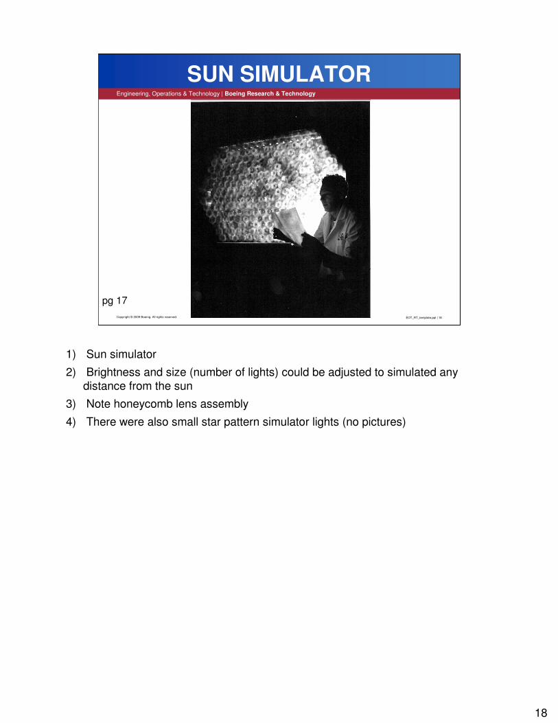
1) Sun simulator
2) Brightness and size (number of lights) could be adjusted to simulated any distance from the sun
3) Note honeycomb lens assembly
4) There were also small star pattern simulator lights (no pictures)

19
EOT_RT_template.ppt | 19
Engineering, Operations & Technology | Boeing Research & Technology
Copyright © 2009 Boeing. All rights reserved.
TEST CONTROL ROOM
pg 18
1) GN&C test control room (early 70s)
2) All the data was collected/recorded on strip chart recorders
3) No digital computers to be seen

20
EOT_RT_template.ppt | 20Copyright © 2009 Boeing. All rights reserved.
Test Article Sensors
pg 19
The following charts show some of the sensors on the test article

21
EOT_RT_template.ppt | 21
Engineering, Operations & Technology | Boeing Research & Technology
Copyright © 2009 Boeing. All rights reserved.
TEST ARTICLE SUN SENSOR
pg 20
1) Sun sensor on the test article that tracked the (simulated) sun’s position
2) Light intensity and position was used for navigation and control
22
EOT_RT_template.ppt | 22
Engineering, Operations & Technology | Boeing Research & Technology
Copyright © 2009 Boeing. All rights reserved.
TEST ARTICLE STAR SENSOR
pg 21
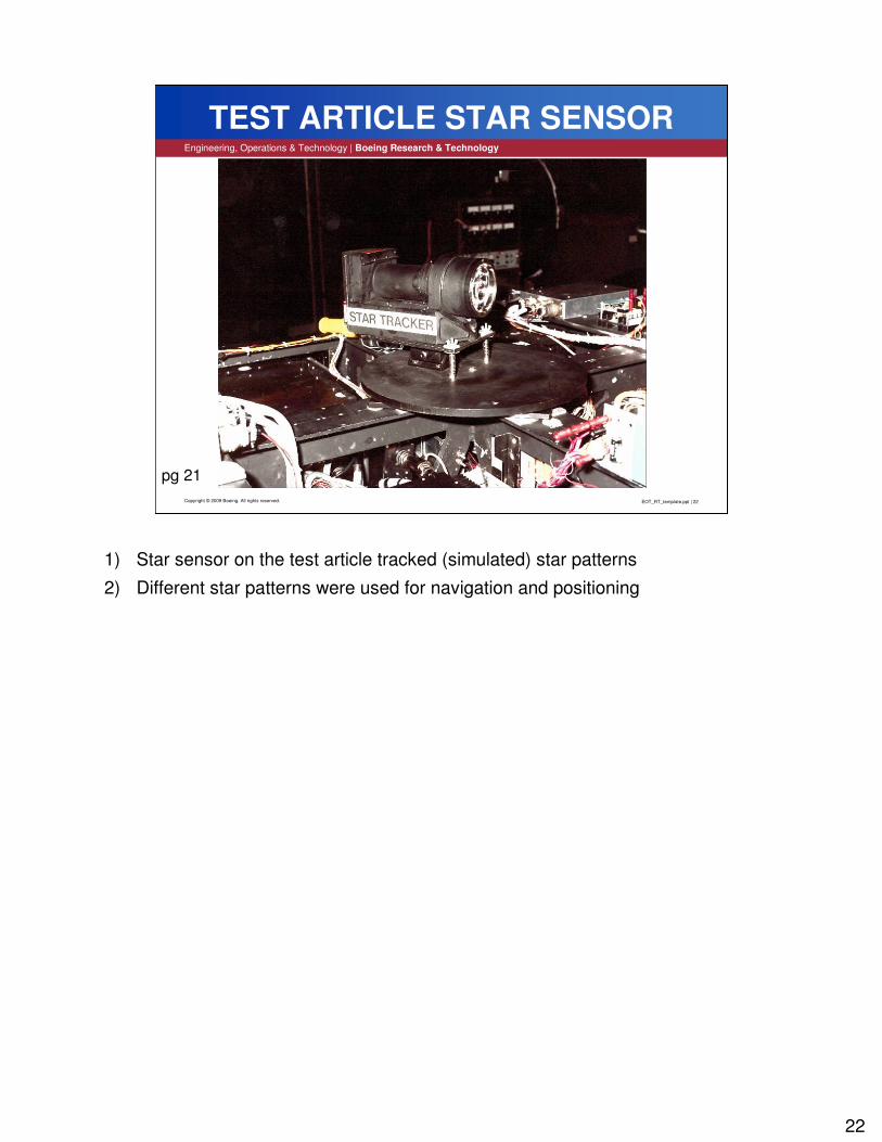
1) Star sensor on the test article tracked (simulated) star patterns
2) Different star patterns were used for navigation and positioning

23
EOT_RT_template.ppt | 23
Engineering, Operations & Technology | Boeing Research & Technology
Copyright © 2009 Boeing. All rights reserved.
TEST ARTICLE DAQ COMPUTER
pg 22
1) Test article’s DAQ computer system
2) 16bit address, 8bit data buss (one antique machine)
3) It’s many battery packs were used as ballast and counter weights
4) Today, one laptop could easily replace it

24
EOT_RT_template.ppt | 24Copyright © 2009 Boeing. All rights reserved.
CMG Test Articles
pg 23
The following charts show some of the different CMG test articles Boeing built

25
EOT_RT_template.ppt | 25
Engineering, Operations & Technology | Boeing Research & Technology
Copyright © 2009 Boeing. All rights reserved.
EARLY CMG TEST ARTICLE – FIRST TYPE
pg 24
1) Early CMG test article on a stand
2) This was a circular unit with small gyros
3) Note white shirt, narrow tie and (analog) VOM - mid 60s

26
EOT_RT_template.ppt | 26
Engineering, Operations & Technology | Boeing Research & Technology
Copyright © 2009 Boeing. All rights reserved.
SAME TEST ARTICLE ON AIR BEARING PAD
pg 25
1) Same test article on the air pad
2) Bowling ball size air bearing
3) Floated on high pressure N2 gas
4) and heavy duty support structure
5) Note white shirt and bow tie – mid 60s

27
EOT_RT_template.ppt | 27
Engineering, Operations & Technology | Boeing Research & Technology
Copyright © 2009 Boeing. All rights reserved.
TEST ARTICLE SHOWING RANGE OF MOTION
pg 26
1) Time laps picture of the test article showing its range of movement
2) Also the test stand could rotate (locked for picture)
3) All Movement was generated by it’s gyros

28
EOT_RT_template.ppt | 28
Engineering, Operations & Technology | Boeing Research & Technology
Copyright © 2009 Boeing. All rights reserved.
EARLY CMG TEST ARTICLE – SECOND TYPE
pg 27
1) Another early type test article
2) Heavy duty tripod stand supporting air bearing and test article
3) Gyros (right) were counter balanced by the DAQ system and battery packs (left)
4) Note mini skirt - late 60s

29
EOT_RT_template.ppt | 29
Engineering, Operations & Technology | Boeing Research & Technology
Copyright © 2009 Boeing. All rights reserved.
MEASURING TEST ARTICLE RANGE OF MOTION
pg 28
1) Test article’s calibration and range of movement (degrees)
2) being measured with protractors and pointers
3) Note sun simulator in the background

30
EOT_RT_template.ppt | 30
Engineering, Operations & Technology | Boeing Research & Technology
Copyright © 2009 Boeing. All rights reserved.
MEDIUM GYRO TEST ARTICLE (right side)
pg 29
1) Right side view of medium gyro test article
2) showing four (4) gimbaled medium CMGs
3) Note hairdo - early 70s

31
EOT_RT_template.ppt | 31
Engineering, Operations & Technology | Boeing Research & Technology
Copyright © 2009 Boeing. All rights reserved.
MEDIUM GYRO TEST ARTICLE (left side)
pg 30
1) Left side view of same medium gyro test article
2) Note colored shirt and lamb chops - early 70s

32
EOT_RT_template.ppt | 32
Engineering, Operations & Technology | Boeing Research & Technology
Copyright © 2009 Boeing. All rights reserved.
LATER VERSION OF MEDIUM GYRO TEST ARTICLE
pg 31
1) Later version medium gyro test article
2) Showing dish antenna and counterweights
3) Note color picture - late 70s

33
EOT_RT_template.ppt | 33
Engineering, Operations & Technology | Boeing Research & Technology
Copyright © 2009 Boeing. All rights reserved.
LARGE GYRO TEST ARTICLE (front view)
pg 32
1) Large gyro test article (front view) showing two of the four gyros (80s – 90s)
2) Looks like the head of an insect (nickname “old bug eyes”)
3) Note sun simulator in the background
4) This test article was in use when I came into the group in 1995

34
EOT_RT_template.ppt | 34
Engineering, Operations & Technology | Boeing Research & Technology
Copyright © 2009 Boeing. All rights reserved.
LARGE GYRO TEST ARTICLE (rear view)
pg 33
1) Rear view of the same test article showing the other two gyros and counter weights
2) If you put a seat on top it would beat any mechanical bull in town
3) However, no one was allowed in the “space (black) room” when it was running
4) Note scratch marks on the air pad (floor), sometimes it got out of control (crashed)

35
EOT_RT_template.ppt | 35
Engineering, Operations & Technology | Boeing Research & Technology
Copyright © 2009 Boeing. All rights reserved.
BALANCE BEAM TEST ARTICLE (front view)
pg 34
Same test article (front view) with balance beam frame for making inertial measurements. Once a satellite achieved orbit it must maintain a stable reference platform.

36
EOT_RT_template.ppt | 36
Engineering, Operations & Technology | Boeing Research & Technology
Copyright © 2009 Boeing. All rights reserved.
BALANCE BEAM TEST ARTICLE (side view)
pg 35
1) Side view of same test article showing the balance beam
2) The balance beam is centered (leveled) on top of test article
3) Note scratch marks on air pad (floor), it did not always work the way it should

37
EOT_RT_template.ppt | 37
Engineering, Operations & Technology | Boeing Research & Technology
Copyright © 2009 Boeing. All rights reserved.
THE END
pg 36
1) This building and GN&C lab (upper left corner) were damaged in the Seattle (2001) earthquake and demolished
2) All the labs and their test equipment were scraped/surplused
3) The rust colored scrap pile (upper left corner) is sitting where the “space (black) room” used to be
4) Because it does not exist any more I can talk about it. Presently, “Amazon.com” has a big warehouse at this exact location

38
EOT_RT_template.ppt | 38
Engineering, Operations & Technology | Boeing Research & Technology
Copyright © 2009 Boeing. All rights reserved.
THANK YOU
pg 37
CONTACT INFO
Mike Gamble
The Boeing Co.
PO Box 3707 M/S 42-51
Seattle, Wa [email protected](206)544-4548 (office)
Hope I have not bored you with too many details – It’s a flaw of engineers! Here’s where you can find me or just catch me in the hall if you have questions.