Embed Size (px)
Citation preview

History of the Development of Beverage Vending Machine Technology in Japan 1
History of the Development of Beverage Vending Machine Technology in Japan
Yoshihiro Higuchi
Abstract Approximately 4.27 million vending machines were operating in Japan at the end of 2006,
with annual sales in excess of 7 trillion yen. We have focused our research on beverage vending machines, because these account for over half of all the installed machines (at 2.60 million).
The first vending machine is thought to have been introduced at a temple in Alexandria in 215 BC. The machine dispensed holy water in return for a small coin. The oldest extant machines are cigarette-vending devices that were installed in English pubs and hostels as early as 1615. English inventors subsequently devised additional designs to sell books, postage stamps, and many other products as well, but the devices were not commercially practical. The first commercially viable vending machines were gum dispensers introduced in the United States. In Japan, the first viable machines were juice vending machines that appeared during the high-growth period following World War II.
While vending machines appear to work without human intervention, an entire support network is active behind the scenes. Machine makers, product manufacturers, operators, service personnel, and location owners are just some of the individuals involved in marketing and management efforts. Other individuals are responsible for route systems that carry out collection, replenishment, and service. When we look back at the history, we see that success rests on gaining the consumer's trust. In the case of beverage machines, the crucial requirements are to maintain merchandise in optimal drinking condition and to ensure safety.
Beverage machines fall into two major categories: the original type that pours the beverage into a cup, and the more recently developed type that delivers prepackaged drinks. The technologies for these two approaches are quite different. With cup-type machines, the machine operator is responsible for both preparing a good-tasting drink and maintaining the safety necessary to attract the consumer. With the prepackaged approach, however, the beverage maker controls the taste, while the machine operator focuses on how best to load containers into the machine and maintain them at optimal temperature.
As the technologies differ, so do the issues that machine designers and operators have to face. Cup-type machines are backed by a long history of development and improvement of basic taste-related components-storing of the ingredients, control of the temperature of the water used in the mix, manufacture of ice and carbonated water for the mix, mixing methods, coffee and tea extraction, cup transport, and so on. With container-type machines, efforts have gone into issues such as effective loading of containers, ease of sales work, design of reliable temperature-control racks, and the design of fast, reliable, container-friendly delivery systems.
Cash collection equipment for vending machines has been widely standardized, which in turn contributes to effective maintenance. Coin mechanisms have advanced from mechanical to electronic. Jamming in the coin channel, which was the biggest problem, has been greatly reduced and the number of supported coins has increased. Where early machines accepted 10-yen coins only, today's machines accept and dispense as change all four main denominations. Built-in electronics enable a wide range of convenient functions, such as display of the amount inserted, tracking and reporting of total sales, and diagnosis of machine errors.
Early coin mechanisms were driven by sequences of relays, but with the coming of the transistor age manufacturers began to incorporate various electronic components. The introduction of ICs and LSIs allowed for multiple functionality, and the subsequent introduction of microprocessors expanded functionality even further. Competition among machine makers spurred innovation, as machines advanced from full contact type (relays only) to hybrid types
2

2 National Museum of Nature and Science: Survey Reports on the Systemization of Technologies Vol.7 2007.March
(with transistors and ICs) and finally to programmed control. The evolution took some time, however, as manufacturers faced numerous quality issues all along the way.
Because vending devices are industrial machines, development of products and technologies in this area has been strongly needs oriented, and has largely been limited to the concept of cash processing. Japanese makers entered the field through technical tie-ups through which they imported the technologies for coin cradles and other basic components and moved toward standardization. They purchased patents for basic electronic coin collection technologies, then implemented various improvements to adapt the technology to the needs of Japanese society and environment. But now that we have fully entered the electronics age, Japan's innovative technologies have positioned the country as a major vending-machine producer. History suggests that increased emphasis on elemental research (a "seeds-oriented" approach) can spur a continuous stream of development proposals, making it possible to break through current barriers and find new ways forward.
Profile Yoshihiro Higuchi Chief Survey Officer, Center of the History of Japanese Industrial Technology, National Museum of Nature and Science March 1961: Graduated from Meiji University
Faculty of Engineering Department of Electrical Engineering
April 1961: Started working for Sanyo Electric Co., Ltd.
Involved in design and development of electronic refrigeration equipment and beverage vending machines for the planning, sales and quality assurance departments before being appointed the vice-director of the vending machine division.
March 1997: Retired from Sanyo April 1997: Appointed as technical supervisor for
the Japan Vending Machine Manufacturers Association
April 2006: Appointed Chief Survey Officer of the Center of the History of Japanese Industrial Technology, National Museum of Nature and Science
Contents 1 Introduction .............................................................. 3 2 Overview of Automatic Vending Machines ............. 5 3 Structure and Function of Beverage Vending
Machines ................................................................ 16 4 Systematization ...................................................... 60 5 Discussion .............................................................. 67 6 Conclusion ............................................................. 69
History of the Development of Beverage Vending Machine Technology in Japan 3
1 Introduction
The vending machines that we see at
every street corner, together with the sale and service of the machines themselves, turned over in excess of seven trillion yen in the year 2000 [1]. This figure rivals the total sales figures of all chain convenience stores across the whole of Japan.
Vending machines sell a great variety of products and appear in every facet of modern Japanese life, from the thirst-quenching beverage vending machines on the street or in the workplace to the ticket vending machines at transport facilities, coin-operated lockers for luggage, money-changing machines and ticket vending machines at restaurants.
According to the 2006 edition of Vending Machine Distribution Statistics and Sales Prices, published by the Japan Vending Machine Manufacturers Association (JMVA), there were 5.52 million vending machines, including automatic service machines, in operation at the end of 2006, of which 4.27 million were vending machines and 1.24 million were automatic service machines. This means that there is one vending machine to every 30 people in Japan.
To clarify what exactly constitutes a vending machine and what types of vending machines there are, a vending machine is defined as “a machine that provides a desired good or service when money (coins or bills) or cards are inserted” [2] [Footnote 1]. Japan Standard Commodity Classification 58 of the Statistics Bureau of the Ministry of Internal Affairs and Communications comprises a middle classification of “vending machines and automatic service equipment,” made up of three small classifications of “vending machines,” “automatic service equipment,” “coin, bill, card equipment and parts of vending machines and automatic service equipment,” and “other vending machines.” The small classification “vending machines” is further divided into “goods vending [Footnote 1]: With product purchases becoming possible by mobile phone or Suica card, the Japan Vending Machine Manufacturers Association is considering revising its terminology dictionary.
machines” and “service vending machines.” According to this distinction of categories, “goods vending machines” sell products such as beverages, food and cigarettes, as well as computer software and other service information, while “service vending machines” are machines that sell actual services, such as coin-operated lockers or coin-operated laundries, as well as money changing machines, which do not actually sell anything.
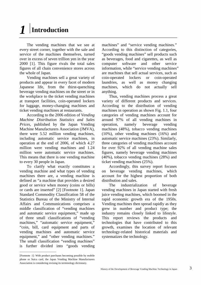
Thus, vending machines process a great variety of different products and services. According to the distribution of vending machines in operation as shown Fig. 1.1, four categories of vending machines account for around 97% of all vending machines in operation, namely beverage vending machines (48%), tobacco vending machines (10%), other vending machines (16%) and automatic service machines (23%). Similarly, three categories of vending machines account for over 92% of all vending machine sales figures, namely beverage vending machines (40%), tobacco vending machines (28%) and ticket vending machines (25%).
Accordingly, this survey report focuses on beverage vending machines, which account for the highest proportion of both distribution and sales.
The industrialization of beverage vending machines in Japan started with fresh juice vending machines, which boomed in the rapid economic growth era of the 1950s. Vending machines then spread rapidly as they grew in number and product type; the industry remains closely linked to lifestyle. This report reviews the products and technologies that have contributed to this growth, examines the location of relevant technology-related historical materials and systematizes the technology.
4 National Museum of Nature and Science: Survey Reports on the Systemization of Technologies Vol.7 2007.March
Fig. 1.1 Vending Machine Distribution
and Sales Statistics Source: Japan Vending Machine Manufacturers Association
In terms of the structure of this paper,
Chapter 2 provides an overview of vending machines, with the first half outlining the emergence of vending machines, from their origins in the form of a holy water dispenser before the Common Era to the various different types of machines that later appeared, both in Japan and overseas. The second half discusses businesses related to the life cycle of a beverage vending machine, such as beverage manufacturers, operators and maintenance service providers, so as to provide an insight into the demand for vending machines. The second half of the chapter also discusses the distribution revolution of the route service system and other management systems, as well as the regulations that relate to beverage vending machines.
Chapter 3 provides a technical discussion on beverage vending machines. The chapter first discusses the fact that there are two types of beverage vending machine, the prepackaged container-type and the cup-type, which have completely different contributing technologies, users and operational methods, and then outlines the history of the technology, component by component, from money processing and vending control systems to product storage and vending equipment, as well as cooling and heating, cooking and processing and displays and service. Chapter 4 provides a technical discussion on the more intangible issues of consumer safety and confidence, touching on aspects such as improving product quality, improving maintainability and the war on crime.
Chapter 5 systematizes the technology related to money handling equipment and cooking/processing in vending machines.
Bibliography [1] “Vending Machine Distribution
Statistics and Sales Prices (2000 edition),” Japan Vending Machine Manufacturers Association.
[2] “Dictionary of Vending Machine Terminology,” Japan Vending Machine Manufacturers Association, p. 37.
Distribution of Vending Machines at the end of 2006
Total number: 5,515,700
Automatic service machines
Other
Tickets Tobacco Food
Beverages
2006 Annual Sales Figures (¥100 million) Total sales: ¥6.8303 trillion
Automatic service
Other
Tickets
Tobacco
Food
Beverages
¥100 million
History of the Development of Beverage Vending Machine Technology in Japan 5
2 Overview of Automatic Vending Machines
2.1 The Origins of Vending Machines The history of vending machines can be
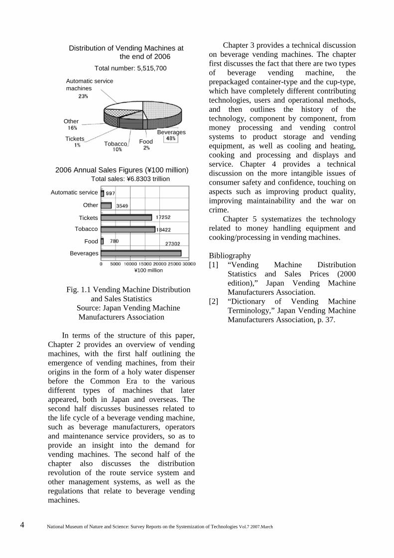
traced back to ancient Egypt. Pneumatica, written by the mathematician and engineer Heron of Alexandria, describes a number of machine inventions applying the properties of air, water and steam. Included among these is an illustrated description of a device that dispensed water (holy water) when a coin was inserted. This is held to be the origin of the vending machine [1].
Although the original text has been lost, a Latin manuscript dating to 1587 has survived and is held in the National Central Library in Rome. According to this work, the coin-operated device was used to sell “sacrificial water” at a temple in Egypt around 250 BCE. When a five-drachma coin was placed in the slot on top, the weight of the coin would lower the receptacle underneath, causing a lever to open the lid covering the spout, thus allowing water to pour out until the receptacle returned to its original position.
The principle behind this is the application of levers; it can still be seen today in our modern-day flush toilets. It is not known if this holy water dispenser was Heron’s own invention or that of his predecessor Tesibius [1].
Fig. 2.1 Holy Water Vending Machine
From 30-Year History of Vending Machines, JVMA
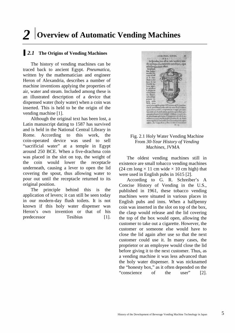
The oldest vending machines still in existence are small tobacco vending machines (24 cm long × 11 cm wide × 10 cm high) that were used in English pubs in 1615 [2].
According to G. R. Schreiber’s A Concise History of Vending in the U.S., published in 1961, these tobacco vending machines were situated in various places in English pubs and inns. When a halfpenny coin was inserted in the slot on top of the box, the clasp would release and the lid covering the top of the box would open, allowing the customer to take out a cigarette. However, the customer or someone else would have to close the lid again after use so that the next customer could use it. In many cases, the proprietor or an employee would close the lid before giving it to the next customer. Thus, as a vending machine it was less advanced than the holy water dispenser. It was nicknamed the “honesty box,” as it often depended on the “conscience of the user” [2].
6 National Museum of Nature and Science: Survey Reports on the Systemization of Technologies Vol.7 2007.March
Fig. 2.2 The “Honesty Box”
“History of the Vending Machine Industry in Europe” [2]
There were machines that sold products
other than tobacco. Richard Carlile, a freethinking bookseller, devised a book vending machine in 1822 to evade the police and public security agencies. This device was described as “selling books by a clockwork mechanism, whereby users put money in and turned the dial to make the desired book come out” [3].
In 1857, Simeon Denham of the United Kingdom invented and patented a stamp vending machine. This is the earliest known vending machine patent [4]. In 1884, William H. Fruen of USA invented an “automatic drawer device” and was granted the first US patent for a vending machine [5]. The first patent application filed in Japan was in March 1888 for an “automatic vending machine” invented by Shuzo Ono of Tokyo, although there is no evidence that it was ever put to practical use [6].
Thus, while vending machine technology started out in the United Kingdom, it spread through Germany, France and Scandinavia, among other places. Inventors interested in the principles of vending machines designed coin-operated metering devices and many different machines selling tobacco, gum, confectionery and other products. Very few were put into practical use; this was an era of inventors rushing to get their ideas patented [7]. For example, although Denham’s patent was granted in 1857, it was not until 1907 that a stamp vending machine operating on the same principles was actually installed at a post office [8]. Getting patent rights and
selling on the market are two different issues entirely.
Although he was later granted several patents, the application documentation recorded that “the machine functioned properly if not deliberately used wrongly, but would easily be damaged if paper, orange peel or other miscellaneous material were inserted into the slot” [9].
A patent by Frederick C. Lynde mentions magnets for checking for false coins and devices for checking dimensions, thickness, weight, outer rim pattern or the presence of a hole [10]. Thus, as it became clear that defective coin mechanisms were the number one reason for being unable to supply products, counterfeit detectors became a specialized field in the vending machine industry [11].
In the 1880s, a shift began from a wave of patents to a wave of implementation. One notable machine in vending machine implementation and development is the American gum vending machine of 1888.
The first time a vending machine was put into actual use in USA was in 1888, when a vending machine developed by Thomas Adams, founder of Adams Gum, was used to sell Adams gum on train station platforms [12]. This format has continued to the present day, successfully developing and expanding the chewing gum vending machine market.
In Germany, a vending machine restaurant that appeared in Berlin in 1895 is said to have been extremely popular. The restaurant comprised only vending machines, allowing customers to dine by putting money into the machines and getting their own meals out. This “fast, hassle-free and tip-free” vending machine concept has continued to the present day [13].
History of the Development of Beverage Vending Machine Technology in Japan 7
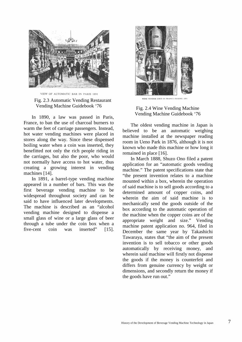
Fig. 2.3 Automatic Vending Restaurant Vending Machine Guidebook ‘76
In 1890, a law was passed in Paris,
France, to ban the use of charcoal burners to warm the feet of carriage passengers. Instead, hot water vending machines were placed in stores along the way. Since these dispensed boiling water when a coin was inserted, they benefitted not only the rich people riding in the carriages, but also the poor, who would not normally have access to hot water, thus creating a growing interest in vending machines [14].
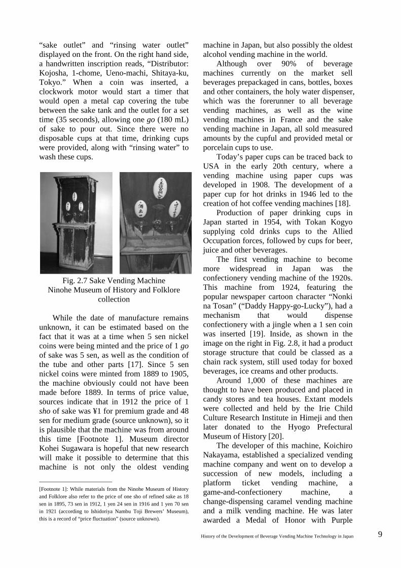
In 1891, a barrel-type vending machine appeared in a number of bars. This was the first beverage vending machine to be widespread throughout society and can be said to have influenced later developments. The machine is described as an “alcohol vending machine designed to dispense a small glass of wine or a large glass of beer through a tube under the coin box when a five-cent coin was inserted” [15].
Fig. 2.4 Wine Vending Machine
Vending Machine Guidebook ‘76
The oldest vending machine in Japan is believed to be an automatic weighing machine installed at the newspaper reading room in Ueno Park in 1876, although it is not known who made this machine or how long it remained in place [16].
In March 1888, Shuzo Ono filed a patent application for an “automatic goods vending machine.” The patent specifications state that “the present invention relates to a machine mounted within a box, wherein the operation of said machine is to sell goods according to a determined amount of copper coins, and wherein the aim of said machine is to mechanically send the goods outside of the box according to the automatic operation of the machine when the copper coins are of the appropriate weight and size.” Vending machine patent application no. 964, filed in December the same year by Takashichi Tawaraya, states that “the aim of the present invention is to sell tobacco or other goods automatically by receiving money, and wherein said machine will firstly not dispense the goods if the money is counterfeit and differs from genuine currency by weight or dimensions, and secondly return the money if the goods have run out.”

8 National Museum of Nature and Science: Survey Reports on the Systemization of Technologies Vol.7 2007.March
Fig. 2.5 Tawaraya Patent Specification Drawing
30-Year History of Vending Machines
In other words, Ono’s patent defined a vending machine as a “machine that sells goods when coins are inserted to the appropriate weight and size,” while Tawaraya’s patent goes as far as to “firstly not dispense the goods if counterfeit money that differs in dimensions or weight from genuine currency is inserted” and to “secondly return the money inserted if the goods are sold out,” even detecting sold-out products and returning the money. While there are no extant examples of either invention or any indication of their practical implementation, the drawings and explanations that appear in the Tawaraya patent (no. 964) show that it even had a counterfeit money rejection function and a money return function if the goods were sold out. Other mechanisms are thought to be original Japanese technology based on the technology used in the mechanized puppets that were substantially developed from the 17th to the 19th century.
Postal Museum Japan has an exhibit featuring the oldest extant vending machine in Japan, an “automatic postage stamp machine” made by Tawaraya in 1904 to sell stamps and postcards. The outer casing of this machine is made of wood and stands 72 cm high, 40 cm wide and 24 cm deep. Viewed from front on, there is a sold-out display window and a coin intake slot on top, with a product vending outlet underneath that, followed by a handle underneath that. At the bottom, there is a returns outlet and a postbox.
Fig. 2.6 Automatic Postage Stamp Machine
Postal Museum Japan collection Specifications of this machine: (1) Selling price: stamps - 3 sen (1 sen + 2
sen), postcards - 1 sen 5 rin (one postcard for 1 sen + 5 rin, two postcards for 1sen + 2 sen)
(2) Operation: Manual (product dispensed by inserting coins and pulling the handle)
(3) Change: Change prepared in advance; if 3 sen was inserted but one postcard was sold out, then 1 sen 5 rin would be given in change
(4) Sold-out display: If there was no more product, the sold-out display would show and the coin intake slot would be blocked off
(5) Validation mechanism: Coins that were too large in diameter would not fit in the intake slot, while coins that were too small in diameter or too thin would be ejected by the coin chute. This mechanism was the same as that in the Tawaraya patent no. 964; the same principle was applied to coin validation devices used in the ¥10 juice vending machines that became popular in the late 1950s and early 1960s. Japan’s earliest beverage vending
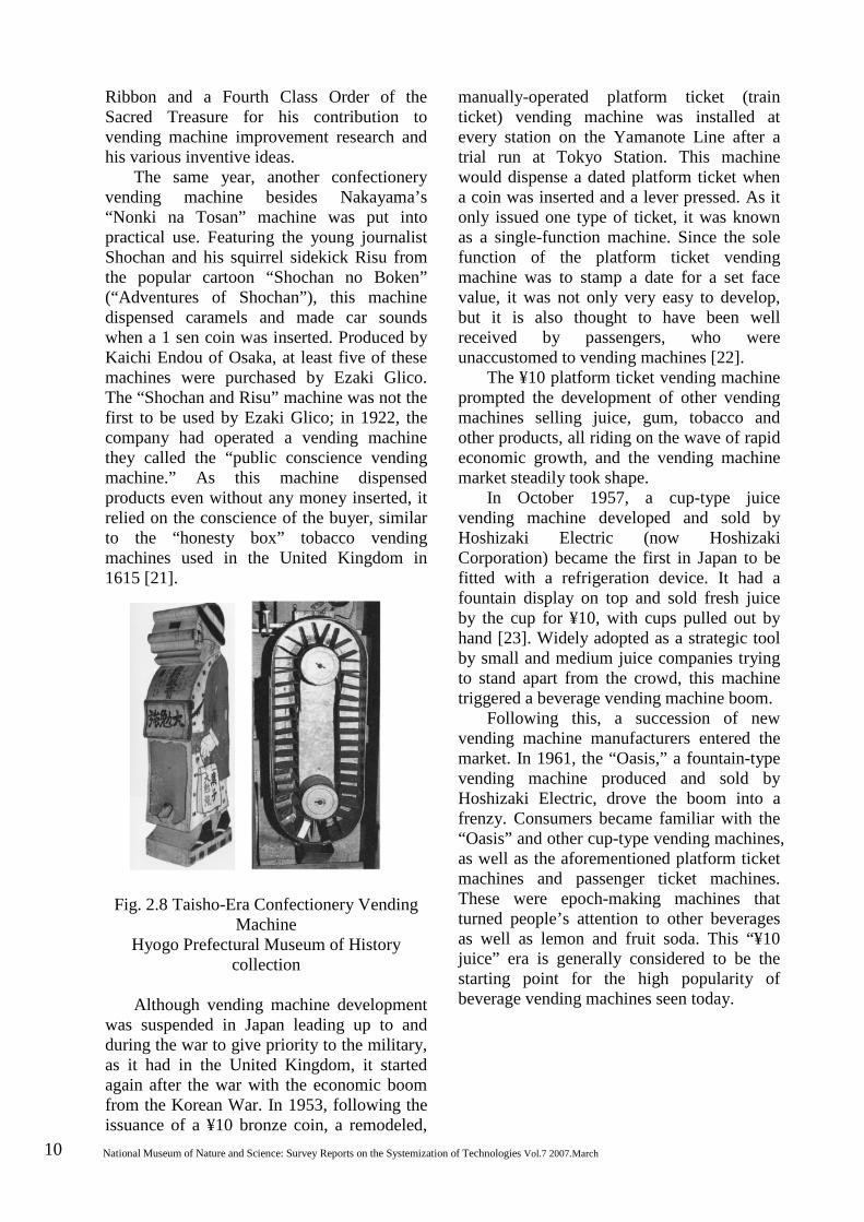
machine was rediscovered in 1987 in a storage room at the residence of the director of brewing company Kuji Shuzo in Ninohe, Iwate. This sake vending machine is now held in the Ninohe Museum of History and Folklore.
Standing 124 cm tall, 45 cm wide and 45 cm deep, the machine has an outer casing of wood and a “5 sen nickel coin intake slot,”
History of the Development of Beverage Vending Machine Technology in Japan 9
“sake outlet” and “rinsing water outlet” displayed on the front. On the right hand side, a handwritten inscription reads, “Distributor: Kojosha, 1-chome, Ueno-machi, Shitaya-ku, Tokyo.” When a coin was inserted, a clockwork motor would start a timer that would open a metal cap covering the tube between the sake tank and the outlet for a set time (35 seconds), allowing one go (180 mL) of sake to pour out. Since there were no disposable cups at that time, drinking cups were provided, along with “rinsing water” to wash these cups.
Fig. 2.7 Sake Vending Machine
Ninohe Museum of History and Folklore collection
While the date of manufacture remains
unknown, it can be estimated based on the fact that it was at a time when 5 sen nickel coins were being minted and the price of 1 go of sake was 5 sen, as well as the condition of the tube and other parts [17]. Since 5 sen nickel coins were minted from 1889 to 1905, the machine obviously could not have been made before 1889. In terms of price value, sources indicate that in 1912 the price of 1 sho of sake was ¥1 for premium grade and 48 sen for medium grade (source unknown), so it is plausible that the machine was from around this time [Footnote 1]. Museum director Kohei Sugawara is hopeful that new research will make it possible to determine that this machine is not only the oldest vending
[Footnote 1]: While materials from the Ninohe Museum of History and Folklore also refer to the price of one sho of refined sake as 18 sen in 1895, 73 sen in 1912, 1 yen 24 sen in 1916 and 1 yen 70 sen in 1921 (according to Ishidoriya Nambu Toji Brewers’ Museum), this is a record of “price fluctuation” (source unknown).
machine in Japan, but also possibly the oldest alcohol vending machine in the world.
Although over 90% of beverage machines currently on the market sell beverages prepackaged in cans, bottles, boxes and other containers, the holy water dispenser, which was the forerunner to all beverage vending machines, as well as the wine vending machines in France and the sake vending machine in Japan, all sold measured amounts by the cupful and provided metal or porcelain cups to use.
Today’s paper cups can be traced back to USA in the early 20th century, where a vending machine using paper cups was developed in 1908. The development of a paper cup for hot drinks in 1946 led to the creation of hot coffee vending machines [18].
Production of paper drinking cups in Japan started in 1954, with Tokan Kogyo supplying cold drinks cups to the Allied Occupation forces, followed by cups for beer, juice and other beverages.
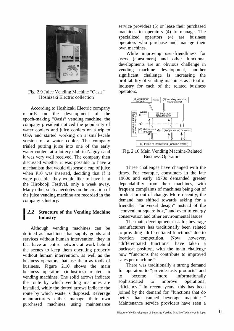
The first vending machine to become more widespread in Japan was the confectionery vending machine of the 1920s. This machine from 1924, featuring the popular newspaper cartoon character “Nonki na Tosan” (“Daddy Happy-go-Lucky”), had a mechanism that would dispense confectionery with a jingle when a 1 sen coin was inserted [19]. Inside, as shown in the image on the right in Fig. 2.8, it had a product storage structure that could be classed as a chain rack system, still used today for boxed beverages, ice creams and other products.
Around 1,000 of these machines are thought to have been produced and placed in candy stores and tea houses. Extant models were collected and held by the Irie Child Culture Research Institute in Himeji and then later donated to the Hyogo Prefectural Museum of History [20].
The developer of this machine, Koichiro Nakayama, established a specialized vending machine company and went on to develop a succession of new models, including a platform ticket vending machine, a game-and-confectionery machine, a change-dispensing caramel vending machine and a milk vending machine. He was later awarded a Medal of Honor with Purple
10 National Museum of Nature and Science: Survey Reports on the Systemization of Technologies Vol.7 2007.March
Ribbon and a Fourth Class Order of the Sacred Treasure for his contribution to vending machine improvement research and his various inventive ideas.
The same year, another confectionery vending machine besides Nakayama’s “Nonki na Tosan” machine was put into practical use. Featuring the young journalist Shochan and his squirrel sidekick Risu from the popular cartoon “Shochan no Boken” (“Adventures of Shochan”), this machine dispensed caramels and made car sounds when a 1 sen coin was inserted. Produced by Kaichi Endou of Osaka, at least five of these machines were purchased by Ezaki Glico. The “Shochan and Risu” machine was not the first to be used by Ezaki Glico; in 1922, the company had operated a vending machine they called the “public conscience vending machine.” As this machine dispensed products even without any money inserted, it relied on the conscience of the buyer, similar to the “honesty box” tobacco vending machines used in the United Kingdom in 1615 [21].
Fig. 2.8 Taisho-Era Confectionery Vending
Machine Hyogo Prefectural Museum of History
collection
Although vending machine development was suspended in Japan leading up to and during the war to give priority to the military, as it had in the United Kingdom, it started again after the war with the economic boom from the Korean War. In 1953, following the issuance of a ¥10 bronze coin, a remodeled,
manually-operated platform ticket (train ticket) vending machine was installed at every station on the Yamanote Line after a trial run at Tokyo Station. This machine would dispense a dated platform ticket when a coin was inserted and a lever pressed. As it only issued one type of ticket, it was known as a single-function machine. Since the sole function of the platform ticket vending machine was to stamp a date for a set face value, it was not only very easy to develop, but it is also thought to have been well received by passengers, who were unaccustomed to vending machines [22].
The ¥10 platform ticket vending machine prompted the development of other vending machines selling juice, gum, tobacco and other products, all riding on the wave of rapid economic growth, and the vending machine market steadily took shape.
In October 1957, a cup-type juice vending machine developed and sold by Hoshizaki Electric (now Hoshizaki Corporation) became the first in Japan to be fitted with a refrigeration device. It had a fountain display on top and sold fresh juice by the cup for ¥10, with cups pulled out by hand [23]. Widely adopted as a strategic tool by small and medium juice companies trying to stand apart from the crowd, this machine triggered a beverage vending machine boom.
Following this, a succession of new vending machine manufacturers entered the market. In 1961, the “Oasis,” a fountain-type vending machine produced and sold by Hoshizaki Electric, drove the boom into a frenzy. Consumers became familiar with the “Oasis” and other cup-type vending machines, as well as the aforementioned platform ticket machines and passenger ticket machines. These were epoch-making machines that turned people’s attention to other beverages as well as lemon and fruit soda. This “¥10 juice” era is generally considered to be the starting point for the high popularity of beverage vending machines seen today.
History of the Development of Beverage Vending Machine Technology in Japan 11
(3) Container supplier
(1) Vending machine manufacturer
(7) Industrial waste
disposal contractor
waste (2) Beverage manufacturer
(5) Maintenance provider (4) Operator (4) Operator
(6) Place of installation (location owner)
Fig. 2.9 Juice Vending Machine “Oasis” Hoshizaki Electric collection
According to Hoshizaki Electric company
records on the development of the epoch-making “Oasis” vending machine, the company president noticed the popularity of water coolers and juice coolers on a trip to USA and started working on a small-scale version of a water cooler. The company trialed putting juice into one of the early water coolers at a lottery club in Nagoya and it was very well received. The company then discussed whether it was possible to have a mechanism that would dispense a cup of juice when ¥10 was inserted, deciding that if it were possible, they would like to have it at the Hirokooji Festival, only a week away. Many other such anecdotes on the creation of the juice vending machine are recorded in the company’s history.
2.2 Structure of the Vending Machine Industry
Although vending machines can be defined as machines that supply goods and services without human intervention, they in fact have an entire network at work behind the scenes to keep them operating properly without human intervention, as well as the business operators that use them as tools of business. Figure 2.10 shows the main business operators (industries) related to vending machines. The solid arrows indicate the route by which vending machines are installed, while the dotted arrows indicate the route by which waste is disposed. Beverage manufacturers either manage their own purchased machines using maintenance
service providers (5) or lease their purchased machines to operators (4) to manage. The specialized operators (4) are business operators who purchase and manage their own machines.
While improving user-friendliness for users (consumers) and other functional developments are an obvious challenge in vending machine development, another significant challenge is increasing the profitability of vending machines as a tool of industry for each of the related business operators.
Fig. 2.10 Main Vending Machine-Related Business Operators
These challenges have changed with the
times. For example, consumers in the late 1960s and early 1970s demanded greater dependability from their machines, with frequent complaints of machines being out of product or out of change. More recently, the demand has shifted towards asking for a friendlier “universal design” instead of the “convenient square box,” and even to energy conservation and other environmental issues.
The main development task for beverage manufacturers has traditionally been related to providing “differentiated functions” due to location competition. Now, however, “differentiated functions” have taken a backseat position, with the main challenge now “functions that contribute to improved sales per machine.”
There was traditionally a strong demand for operators to “provide tasty products” and to become “more informationally sophisticated to improve operational efficiency.” In recent years, this has been joined by the demand for “functions that do better than canned beverage machines.” Maintenance service providers have seen a
12 National Museum of Nature and Science: Survey Reports on the Systemization of Technologies Vol.7 2007.March
shift in demand from “decreased callouts (fault repairs)” to “improved workability through standardization and easier disassembly.” Although they have no direct contact with vending machine manufacturers, there has also been increased demand from waste disposal operators from around the year 2000 under the extended producer responsibility system.
Even the structure of the industry shown in the previous figure is beginning to change as society ushers in a “mobile phone culture,” having become more informationally sophisticated.
This is due to the fact that the so-called IT industry must now play a part in the industry, with vending machines becoming social facilities and terminals of information culture.
2.3 Operational Format of Beverage Vending Machines
The ¥10 juice boom fell into rapid
decline with a cold summer in 1963. While 20-Year History of Vending Machines attributes this decline to pricing policies and changes in consumer tastes, the fact cannot be ignored that consumers may have also been put off by vending machine troubles (such as breakdowns) or by issues with beverage quality.
With the spread of the ¥10 juice machines and national railway ticket machines giving consumers the chance to get acquainted with vending machines, Coca-Cola Japan [Footnote 2] entered the market armed with a route sales system using its own vending machines. The company installed tens of thousands of vending machines per year, offering two systematic services: the “regular service,” which entailed leasing machines to retail stores to manage, and the “full service,” which involved taking offers for vending machine locations and then handling everything from product stocking to [Footnote 2]: Nihon Inryo Kogyo was established in 1957 as the Japanese base for The Coca-Cola Company of USA, later changing its name to Coca-Cola Japan in 1958. The company became the core of the Coca-Cola Group, in charge of planning, research and development and concentrate manufacturing, while bottlers around the country were responsible for product manufacture, distribution and sales.
hygiene management and sales management. This aggressive introduction of vending
machines by the Coca-Cola Group [Footnote 3] began in 1962 and soon took up most of the demand for beverage vending machines.
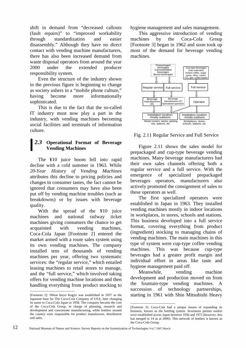
Fig. 2.11 Regular Service and Full Service
Figure 2.11 shows the sales model for prepackaged and cup-type beverage vending machines. Many beverage manufacturers had their own sales channels offering both a regular service and a full service. With the emergence of specialized prepackaged beverages operators, manufacturers also actively promoted the consignment of sales to these operators as well.
The first specialized operators were established in Japan in 1963. They installed vending machines mostly in indoor locations in workplaces, in stores, schools and stations. This business developed into a full service format, covering everything from product (ingredient) stocking to managing chains of vending machines. The main machines in this type of system were cup-type coffee vending machines. This was because cup-type beverages had a greater profit margin and individual effort in areas like taste and hygiene management paid off.
Meanwhile, vending machine development and production moved on from the fountain-type vending machines. A succession of technology partnerships, starting in 1961 with Shin Mitsubishi Heavy [Footnote 3]: Coca-Cola had a unique means of expanding its business, known as the bottling system. Seventeen partner outlets were established across Japan between 1956 and 1972 (however, this has merged to 14 as at 2006). This network of bottlers is known as the Coca-Cola Group.
Prepackaged beverages
Canned/bottled beverages
Boxed beverages
Cup-type beverages (raw materials)
Instant coffee, sugar, syrup, other, cream,
CO2 gas, coffee beans
Regular service Full service Full service
Beverage manufacturers
(R)
Beverage manufacturers (F)
Specialized operators Operator
Installation location: mostly outdoors
Installation location: mostly outdoors
Street corners, stores, parking lots, stations, etc.
Workplaces, stores, schools, stations, etc.
History of the Development of Beverage Vending Machine Technology in Japan 13
Industries (now Mitsubishi Heavy Industries) and Tsugami Manufacturing (now Tsugami Corporation) forming technology partnerships with American vending machine manufacturers, gradually led to the domestic production based on imported technology. Since this initiative focused on the aforementioned vending machine strategy of the Coca-Cola Group, Shin Mitsubishi Heavy Industries teamed up with The Vendo Co., the most successful American company in the Coca-Cola market. The first two machines produced through this partnership were bottle vending machines for the Coca-Cola Group.
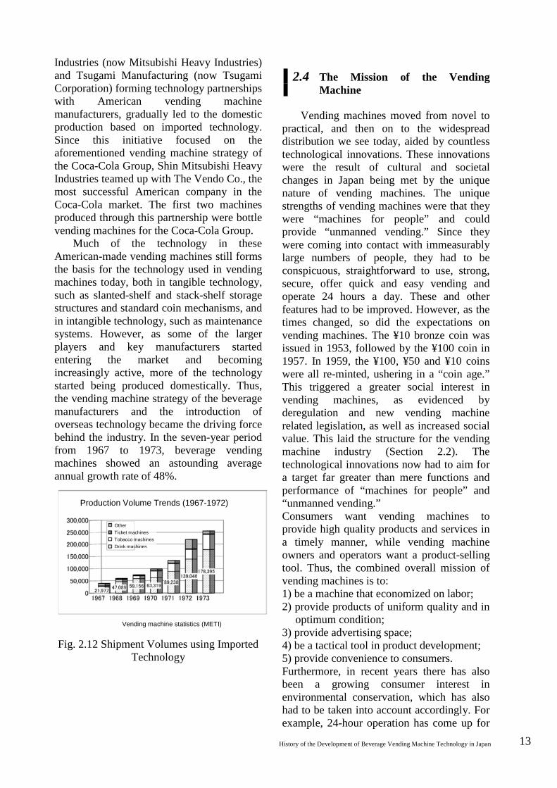
Much of the technology in these American-made vending machines still forms the basis for the technology used in vending machines today, both in tangible technology, such as slanted-shelf and stack-shelf storage structures and standard coin mechanisms, and in intangible technology, such as maintenance systems. However, as some of the larger players and key manufacturers started entering the market and becoming increasingly active, more of the technology started being produced domestically. Thus, the vending machine strategy of the beverage manufacturers and the introduction of overseas technology became the driving force behind the industry. In the seven-year period from 1967 to 1973, beverage vending machines showed an astounding average annual growth rate of 48%.
Fig. 2.12 Shipment Volumes using Imported Technology
2.4 The Mission of the Vending Machine
Vending machines moved from novel to practical, and then on to the widespread distribution we see today, aided by countless technological innovations. These innovations were the result of cultural and societal changes in Japan being met by the unique nature of vending machines. The unique strengths of vending machines were that they were “machines for people” and could provide “unmanned vending.” Since they were coming into contact with immeasurably large numbers of people, they had to be conspicuous, straightforward to use, strong, secure, offer quick and easy vending and operate 24 hours a day. These and other features had to be improved. However, as the times changed, so did the expectations on vending machines. The ¥10 bronze coin was issued in 1953, followed by the ¥100 coin in 1957. In 1959, the ¥100, ¥50 and ¥10 coins were all re-minted, ushering in a “coin age.” This triggered a greater social interest in vending machines, as evidenced by deregulation and new vending machine related legislation, as well as increased social value. This laid the structure for the vending machine industry (Section 2.2). The technological innovations now had to aim for a target far greater than mere functions and performance of “machines for people” and “unmanned vending.” Consumers want vending machines to provide high quality products and services in a timely manner, while vending machine owners and operators want a product-selling tool. Thus, the combined overall mission of vending machines is to: 1) be a machine that economized on labor; 2) provide products of uniform quality and in
optimum condition; 3) provide advertising space; 4) be a tactical tool in product development; 5) provide convenience to consumers. Furthermore, in recent years there has also been a growing consumer interest in environmental conservation, which has also had to be taken into account accordingly. For example, 24-hour operation has come up for
Production Volume Trends (1967-1972)
Other Ticket machines Tobacco machines Drink machines
Vending machine statistics (METI)
14 National Museum of Nature and Science: Survey Reports on the Systemization of Technologies Vol.7 2007.March
reconsideration, because this provision of convenience has resulted in greater energy consumption. “On-the-spot” consumption has also resulted in increased waste, while excessive illumination and the use of vending machines for advertising have made them into a blot on the landscape. Optimum product temperature control and energy-conserving operation are not compatible. These once-sought-after functions and roles are now being re-examined for the sake of the environment and new demands need to be met.
2.5 Safety of Beverage Vending Machines
One of the reasons that beverage vending machines have become so widespread is the level of trust that has been built up between the consumers and the machines. Consumers know that they can safely use these machines, that they can put their money into them with confidence, that the product they receive from the machine will be fresh and at the appropriate temperature and that any issues will be resolved. If you cannot gain consumer trust, you cannot gain their business.
Various legislations have served as guidelines in establishing these safety standards.
Under the Electrical Appliance and Material Safety Act passed in 1961, vending machines that have heating or cooling devices are classed as Class A electrical appliances and must have guaranteed electrical safety based on specified technical standards.
A notification was issued based on Article 7 (standards for cooking) and Article 10 (standards for containers and packaging) of the Food Sanitation Act of 1961. According to this notification, cup-type beverage vending machines are designated as devices “having structures with components that come into direct contact with food.” Compliance standards were established, giving peace of mind to consumers [Footnote 4]. These standards are [Footnote 4]: The first regulation to be enacted in relation to vending machines was the Ministry of Health and Welfare Notification Specifications and Standards for Food and Food Additives, etc., based on the Food Sanitation Act of June 1961, which specified the production standards and storage standards for drinking water, in
wide-ranging, including: (1) regulations on structure and functions; (2) regulations on cooking; (3) regulations on operational management; (4) regulations on installation locations; (5) regulations on operating permits.
(1) specifies such things as component material, cleaning- and sterilization-capable structures, food storage structures and the handling of cups for sale; (2) specifies such things as cooking at sale, temperatures used for cooking and sales cancel functions; (5) means that café business permits are required for vending machines selling soft drink or coffee that is not prepackaged. Since many of the cup-type beverage vending machines take their water directly from a water supply, they are also obliged to comply with the standards under the Water Supply Act as well as the Food Sanitation Act. Furthermore, all vending machine installations have to comply with road usage regulations based on the Road Act and the Road Traffic Act; installations at gas stations must be permitted under the Fire Service Act; money and card handling must comply with the Penal Code, the Law Concerning the Regulation of Counterfeit Currency and Securities and the Act on Control of Damaging and Other Acts Related to Coins.
Bibliography [1] “20-Year History of Vending
Machines,” Japan Vending Machine Manufacturers Association, p. 6.
[2] “History of the Vending Machine Industry in Europe,” Vending Machines, Vending Machine News, p. 6.
[3] “History of the Vending Machine Industry in Europe,” Vending Machines, Vending Machine News, p. 7.
[4] “History of the Vending Machine Industry in Europe,” Vending Machines, Vending Machine News, p. 7.
[5] “History of the Vending Machine Industry in the United States of America,” Vending Machine News, p. 5.
[6] T. Washizu, “Cultural History of
order to ensure the food hygiene of cup-type beverage vending machines, which started rapidly growing in popularity from the late 1950s.
History of the Development of Beverage Vending Machine Technology in Japan 15
Vending Machines,” p. 23. [7] “History of the Vending Machine
Industry in the United States of America,” Vending Machine News, p. 4.
[8] “History of the Vending Machine Industry in Europe,” Vending Machines, Vending Machine News, p. 7.
[9] “History of the Vending Machine Industry in Europe,” Vending Machines, Vending Machine News, p. 8.
[10] “History of the Vending Machine Industry in Europe,” Vending Machines, Vending Machine News, p. 9.
[11] “History of the Vending Machine Industry in Europe,” Vending Machines, Vending Machine News, p. 9.
[12] G. R. Schreiber, “A Concise History of Vending in the U.S.,” p. 13.
[13] T. Washizu, “Cultural History of Vending Machines,” p. 41.
[14] “History of the Vending Machine Industry in the United States of America,” Vending Machine News, p. 6.
[15] “History of the Vending Machine Industry in the United States of America,” Vending Machine News, p. 6.
[16] T. Washizu, “Cultural History of Vending Machines,” p. 72.
[17] T. Washizu, “Cultural History of Vending Machines,” pp. 84-86.
[18] Tokan Kogyo Co., Ltd. website. [19] “30-Year History of Vending
Machines,” Japan Vending Machine Manufacturers Association, p. 5.
[20] “30-Year History of Vending Machines,” Japan Vending Machine Manufacturers Association, p. 5.
[21] “30-Year History of Vending Machines,” Japan Vending Machine Manufacturers Association, p. 5.
[22] “20-Year History of Vending Machines,” Japan Vending Machine Manufacturers Association, p. 115.
[23] “50-Year History of Hoshizaki,” Hoshizaki Corporation, p. 92

16 National Museum of Nature and Science: Survey Reports on the Systemization of Technologies Vol.7 2007.March
3 Structure and Function of Beverage Vending Machines
3.1 Types of Beverage Vending Machines
Beverage vending machines can be
broadly grouped into two categories: cup-type vending machines, such as early Japanese sake vending machines and Heron’s holy water dispenser, considered to be the oldest vending machine in the world, and prepackaged beverage vending machines, selling beverages in bottles, cans and boxes.
Table 3.1 shows the main differences between the two types. In terms of technology development, since the functions of the former cover everything from cooking or processing the ingredients to produce the beverage through to pouring the beverage into its container (Fig. 3.1), the technology has been aimed at “providing good taste” and “managing food hygiene.” By contrast, since the functions of the latter are geared towards efficiently storing (Fig. 3.2) beverages produced and packaged by beverage manufacturers and selling those beverages at their optimum temperature, development has been aimed at “handling a variety of beverages” and “control technology to provide beverages at their optimum temperature.”
Table 3.1 Types and Features of Beverage Vending Machines
Cup-type Beverage Vending Machine
Prepackaged Beverage Vending
Machine
Structure
Equipped with cooling tank, hot water tank, ice maker, water/ingredients tank, CO2 gas, cup dispenser, etc. Cooks/processes ingredients to produce and sell beverages one cup at a time.
Heats/cools containers (beverages) according to their type and sells them one at a time.
Machine purchaser
Specialized operators Non-specialized operators
Beverage manufacturers Sake brewers
Main installation locations
Workplaces/stores/schools/public facilities
in stores On the street
Regulated by
Compliance with Food Sanitation Act Business permits
Fig. 3.1 Example Cup-Type Beverage
Machine Beverage Production (Source: Kaitai Shinsho, Nikkan Kogyo
Shimbun)
cannister
(1) Beans drop into mill from
cannister
mill Distilled while mixed
with air screw rotates
to extrude ingredients
brewer
air filter
water spill
spill valve heater
spill tank (3) Ingredients drop from
cannister into mixing bowl
mixing bowl
(4) Distilled coffee and sugar, etc. stirred with stirring blades
stirring blades
vending outlet
(5) Poured into cup
(2) Powder and hot water poured into
brewer and distilled with air added
Coffee grounds drop into bucket
cannister

History of the Development of Beverage Vending Machine Technology in Japan 17
Fig. 3.2 Storage Example (Source: Vending Machine Technical Review)
3.2 History of Technology Developments
3.2.1 Cup-Type Vending Machines
The fresh juice vending machines that were developed in the late 1950s, triggering a major boom and playing a significant part in later vending machine industrialization, were cup-type vending machines. Since the machines in those days had no cup dispensers (devices that automatically place a cup into the vending outlet), the procedure for purchasing juice was to first take a cup by hand from a cup storage cylinder mounted on the side or the front of the machine, place it in the designated space in the vending outlet and then insert ¥10. Although an improved model did emerge in this “manual cup” era with an optical cup detector built in to the vending outlet as a countermeasure against forgetting to place the cup, cup dispensers were eventually either imported from overseas or produced through licensed overseas technology, while regulation by the Food Sanitation Act ultimately spelled the end of the “manual cup” method. The optical cup detector that had been developed was a switching circuit using newly-implemented transistors and it drew some attention as the first such electronic circuit to be used in the industry.
Structurally, cup-type beverage vending machines can be categorized into cold beverage machines and hot beverage
machines. There are also two types of cold beverage machines: the post-mix type, in which the beverage is prepared from syrup or other raw ingredients and mixed with chilled water at the time of sale, and the pre-mix type, in which the beverage is produced in advance by the beverage manufacturer, stored chilled in the machine and then poured into the cup in predetermined amounts at the time of sale. The distinguishing features of these two types are shown in Table 3.2.
Nowadays, there are hardly any pre-mix machines on the market due to difficulties with hygiene management and other issues.
Table 3.2 Types and Features of Beverage Vending Machines
Post-mix (stored as raw ingredients and then made into beverage at the time of sale)
The ratio of syrup to water is around 1:4–5, reducing transportation costs per weight or volume by 5 to 6 times; syrup has superior bacteria resistance due to its high acidity and high sugar concentration.
Pre-mix (stored and sold in beverage state)
These machines are simple in structure as they do not require any beverage producing equipment; however, they require very frequent cleaning at high temperature, since beverages are less bacteria-resistant.
While cold beverage vending machines
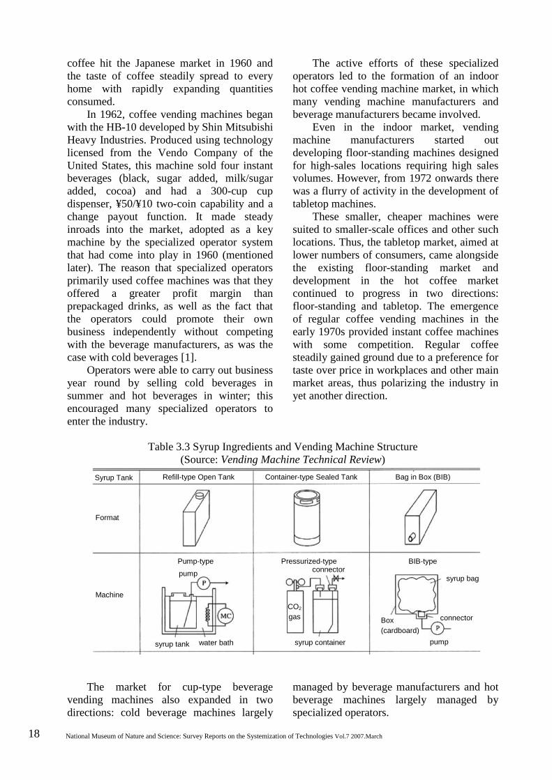
mostly use syrup as a raw ingredient, they vary in structure depending on the syrup storage system used (Table 3.3). A system in which syrup is stored in refillable open tanks and then pumped out and diluted with chilled or carbonated water (the pump system) has primarily been adopted by the operator industry. The Coca-Cola Group, which as a beverage manufacturer produces syrup, introduced a system in which the syrup is produced at the factory and transported in sealed tanks, which are then stored within the vending machine pressurized with CO2 gas, which is also used to extract the syrup at the time of sale (the pressure system). A third system was introduced, in which the tank used in the pump system is replaced by a disposable Bag-in-Box (BiB), thus making three syrup storage and delivery systems.
Hot beverage vending machines are inseparably linked to instant coffee. Instant
18 National Museum of Nature and Science: Survey Reports on the Systemization of Technologies Vol.7 2007.March
coffee hit the Japanese market in 1960 and the taste of coffee steadily spread to every home with rapidly expanding quantities consumed.
In 1962, coffee vending machines began with the HB-10 developed by Shin Mitsubishi Heavy Industries. Produced using technology licensed from the Vendo Company of the United States, this machine sold four instant beverages (black, sugar added, milk/sugar added, cocoa) and had a 300-cup cup dispenser, ¥50/¥10 two-coin capability and a change payout function. It made steady inroads into the market, adopted as a key machine by the specialized operator system that had come into play in 1960 (mentioned later). The reason that specialized operators primarily used coffee machines was that they offered a greater profit margin than prepackaged drinks, as well as the fact that the operators could promote their own business independently without competing with the beverage manufacturers, as was the case with cold beverages [1].
Operators were able to carry out business year round by selling cold beverages in summer and hot beverages in winter; this encouraged many specialized operators to enter the industry.
The active efforts of these specialized operators led to the formation of an indoor hot coffee vending machine market, in which many vending machine manufacturers and beverage manufacturers became involved.
Even in the indoor market, vending machine manufacturers started out developing floor-standing machines designed for high-sales locations requiring high sales volumes. However, from 1972 onwards there was a flurry of activity in the development of tabletop machines.
These smaller, cheaper machines were suited to smaller-scale offices and other such locations. Thus, the tabletop market, aimed at lower numbers of consumers, came alongside the existing floor-standing market and development in the hot coffee market continued to progress in two directions: floor-standing and tabletop. The emergence of regular coffee vending machines in the early 1970s provided instant coffee machines with some competition. Regular coffee steadily gained ground due to a preference for taste over price in workplaces and other main market areas, thus polarizing the industry in yet another direction.
Table 3.3 Syrup Ingredients and Vending Machine Structure (Source: Vending Machine Technical Review)
The market for cup-type beverage vending machines also expanded in two directions: cold beverage machines largely
managed by beverage manufacturers and hot beverage machines largely managed by specialized operators.
Syrup Tank Refill-type Open Tank Container-type Sealed Tank Bag in Box (BIB)
Format
Machine
Pump-type pump
syrup tank water bath
Pressurized-type connector
CO2 gas
syrup container
BIB-type
syrup bag
Box (cardboard)
connector
pump
Syrup Tank Refill-type Open Tank Container-type Sealed Tank Bag in Box (BIB)
Format
Machine
Pump-type pump
syrup tank water bath
Pressurized-type connector
CO2 gas
syrup container
BIB-type
syrup bag
Box (cardboard)
connector
pump

History of the Development of Beverage Vending Machine Technology in Japan 19
The emergence of a hot and cold regular coffee machine in 1974 made it possible for coffee machines to be used all year round. Once Fuji Denki developed a hot and cold multi-flavor cup-type vending machine in 1976 [2], it became possible for both beverage manufacturers and specialized operators to have hot and cold machines by fitting previously primarily syrup-based cold beverage machines with a hot coffee function.
Following the transition to combined hot and cold machines, food manufacturers and vending machine manufacturers turned their efforts to developing flavors, resulting in further expansion into the multi-flavor arena, including leaf tea and soups. One such development by Sanden in 1981 was a vending machine with an attached mill (coffee grinder) [3], which gained much attention for its complete devotion to taste. Cup-type vending machines were increasing in quality, diversity and scale.
As well as the basic functions of producing the beverage by means of equipment such as a raw ingredient storage device, a water bath for chilling drinking water, a hot water tank for heating hot water, a carbonation device or an ice maker, placing the cup into the vending outlet at the time of sale and pouring a fixed amount of the beverage into the cup, it was also a very essential function for cup-type vending machines to undergo regular hygiene management, whether daily, weekly or monthly, thus making them extremely complex to manage.
Consequently, the transition to electronics has been a long one. A cold beverage machine developed by Sanyo Electric in 1973 contained a transistor sequence circuit; the same machine was made more multifunctional with the adoption of ICs, LSI and microcomputers [4].
Not only has microcomputer technology in particular been very successful in controlling the internal functions of vending machines, such as cup detection, sold-out detection and other sensing functions, raw ingredient mixing sequence control, various test functions, sanitation functions and monitor display functions, it has also played a significant part in improving operational
efficiency through computerization, such as maintenance information systems and sales information systems for new product development or route sales efficiency. 3.2.2 Prepackaged Beverage Vending
Machines While cup-type beverage vending
machines selling fresh juice for ¥10 per cup performed very well around the country as a strategic sales tool by small-to-medium beverage manufacturers producing lemon or fruit sodas, this came to an end within around five years with the appearance of prepackaged cola beverage vending machines. Nihon Inryo Kogyo, established in 1957 (name changed to Coca-Cola Japan the following year), actively expanded on its vending machine strategy, armed with its own franchise system and route sales system.
One distinguishing characteristic of this system was that all of the vending machines and parts used by the bottling companies had to be “certified” by Coca-Cola Japan, just as they were in the American market [5]. In order to quickly adapt to this system, companies in Japan were prompt to form technology partnerships with high-performing manufacturers in the United States. In 1961, Shin Mitsubishi Heavy Industries partnered with the Vendo Company of the United States to prepare a supply system using technology from the country with the most advanced vending machine technology in the world at that time. Two bottle vending machines (the V-63 and the V-144) were produced commercially in 1962, initially using knock-down assembly and later using a gradually-increasing number of parts produced in Japan. Although the success in the United States is due a certain amount of credit from the perspective of the bottling companies purchasing the machines, the quality and functions were not suitable for Japan and there was a growing expectation for products to be developed for use in Japan using Japanese technology. The market began to change, with Japanese electronics manufacturers taking center stage as they developed products using their own technology.
20 National Museum of Nature and Science: Survey Reports on the Systemization of Technologies Vol.7 2007.March
The system of “certification” by machine buyers was a process in which buyers set standards for vending machine functions and specifications and then checked to certify whether or not those standards had been met. Although this system meant that it was difficult for machine manufacturers to gain a monopoly using their own technology, it had recognizable benefits in that it promoted the standardization of parts and functions, which improved operational technology and maintainability. Even today, there are mechanisms for component development within the framework of the “independent beverage manufacturer specification and certification” system.
The development of prepackaged beverage vending machines is of course closely linked to changes in packaging.
With changes in beverage containers prompting various different technological developments, glass bottles were the first containers used for soft drinks; accordingly, the first soft drink machine was a glass bottle vending machine. The transition to cans began around 1965; by the early 1970s, almost all glass bottle vending machines had been replaced by canned beverage vending machines.
Although an amendment to the Food Sanitation Law in 1982 allowed the use of PET bottles for soft drinks, these 500 mL and other small drink bottles did not gain popularity until the Japan Soft Drink Association abolished self-regulation in 1996. As soft drink containers changed materially from glass bottles to cans to PET bottles, various different types of containers and shapes appeared with each material. Accordingly, developments in prepackaged beverage vending machines revolved around developing various different types of storage and vending equipment compatible with each new container.
Milk packaging dates back to around 1881, when milk started being home delivered to customers on foot, packed into small tin cans (1 go: 180 mL) [6].
However, the demand for hygiene management grew as civilization progressed. Easily washable “narrow mouthed glass bottles” appeared in Tokyo in 1889, followed
by the emergence of “milk-only glass bottles” in 1899. Thus, the traditional tin cans were replaced by glass bottles that were hygienic and easy to carry.
Overseas, the Swedish government proposed the development of a tetrahedron-shaped cardboard carton called the Tetra Pak in the mid-20th century, while the United States developed the Pure-Pak, a similar cardboard rectangular carton with a roof-shaped top. These grew in popularity as milk containers.
Dairy cooperatives in Japan introduced the Swedish-developed Tetra Pak (Tetra Classic) in 1956 and it spread rapidly in use, being adopted for use in school lunches and at the 1964 Tokyo Olympics [7]. However, it was gradually replaced by the rectangular Pure Pak due to difficulties with transporting, storing and displaying the characteristic tetrahedron-shaped packages.
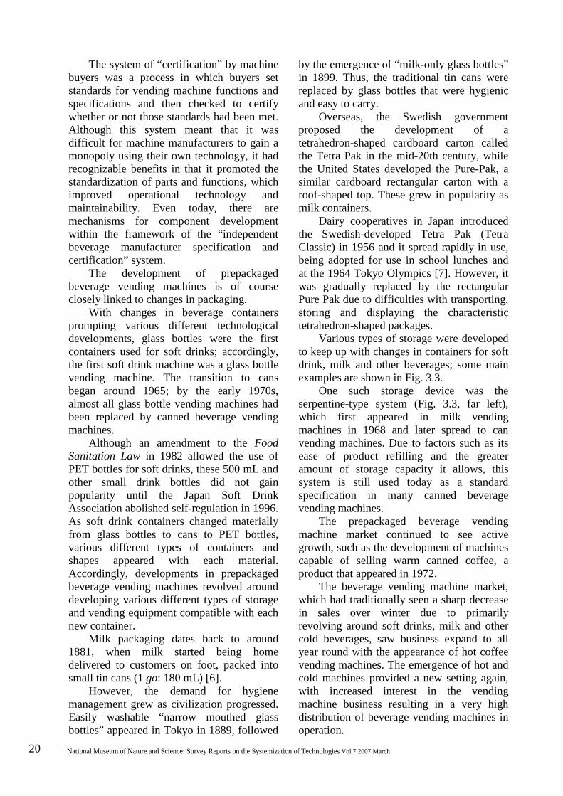
Various types of storage were developed to keep up with changes in containers for soft drink, milk and other beverages; some main examples are shown in Fig. 3.3.
One such storage device was the serpentine-type system (Fig. 3.3, far left), which first appeared in milk vending machines in 1968 and later spread to can vending machines. Due to factors such as its ease of product refilling and the greater amount of storage capacity it allows, this system is still used today as a standard specification in many canned beverage vending machines.
The prepackaged beverage vending machine market continued to see active growth, such as the development of machines capable of selling warm canned coffee, a product that appeared in 1972.
The beverage vending machine market, which had traditionally seen a sharp decrease in sales over winter due to primarily revolving around soft drinks, milk and other cold beverages, saw business expand to all year round with the appearance of hot coffee vending machines. The emergence of hot and cold machines provided a new setting again, with increased interest in the vending machine business resulting in a very high distribution of beverage vending machines in operation.
History of the Development of Beverage Vending Machine Technology in Japan 21
・Calculate amounts ・Determine selling availability ・Change payout display ・Infer sales behavior ・Price setting ・Sales information ・Energy-saving setting ・Process ・Temperature control
・Coin validation ・Banknote identification ・Card reading ・Writing ・Cashless capability ・Giving change ・Temporary ・Banknote storing
Information/service mechanism
Control information processing mechanism
Mon
ey h
andl
ing
mec
hani
sm
Stor
ing/
sellin
g m
echa
nism
・Product display ・Sold-out display ・Selection buttons ・Price display ・Money intake slot ・Vending outlet ・Return outlet ・Money safe
・Product ingredient storage ・Cooling/heating ・Sold-out detection ・Selling device ・Transporting device ・Sale information ・Energy-saving setting ・Temperature detection ・Water storage tank ・Hot water tank ・Cooling water bath ・Ice making ・Other devices
Fig. 3.3 Storage Examples
(Source: Vending Machine Technical Review)
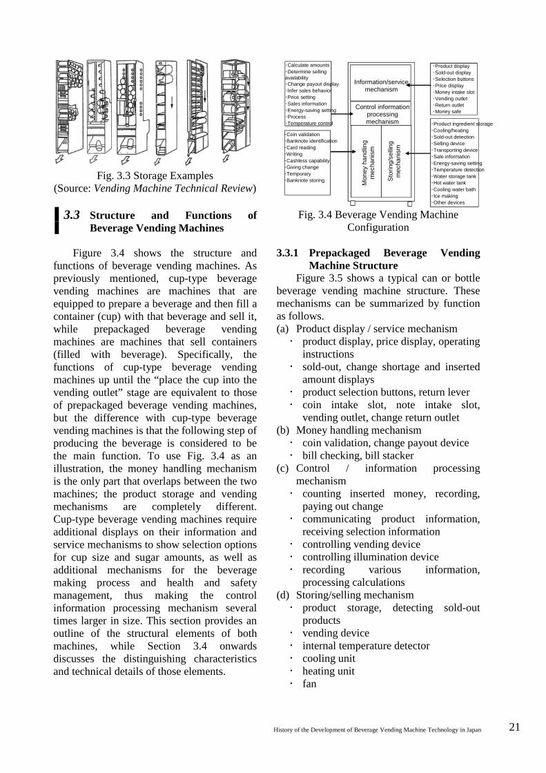
3.3 Structure and Functions of Beverage Vending Machines
Figure 3.4 shows the structure and functions of beverage vending machines. As previously mentioned, cup-type beverage vending machines are machines that are equipped to prepare a beverage and then fill a container (cup) with that beverage and sell it, while prepackaged beverage vending machines are machines that sell containers (filled with beverage). Specifically, the functions of cup-type beverage vending machines up until the “place the cup into the vending outlet” stage are equivalent to those of prepackaged beverage vending machines, but the difference with cup-type beverage vending machines is that the following step of producing the beverage is considered to be the main function. To use Fig. 3.4 as an illustration, the money handling mechanism is the only part that overlaps between the two machines; the product storage and vending mechanisms are completely different. Cup-type beverage vending machines require additional displays on their information and service mechanisms to show selection options for cup size and sugar amounts, as well as additional mechanisms for the beverage making process and health and safety management, thus making the control information processing mechanism several times larger in size. This section provides an outline of the structural elements of both machines, while Section 3.4 onwards discusses the distinguishing characteristics and technical details of those elements.
Fig. 3.4 Beverage Vending Machine Configuration
3.3.1 Prepackaged Beverage Vending
Machine Structure Figure 3.5 shows a typical can or bottle
beverage vending machine structure. These mechanisms can be summarized by function as follows. (a) Product display / service mechanism product display, price display, operating
instructions sold-out, change shortage and inserted
amount displays product selection buttons, return lever coin intake slot, note intake slot,
vending outlet, change return outlet (b) Money handling mechanism coin validation, change payout device bill checking, bill stacker
(c) Control / information processing mechanism counting inserted money, recording,
paying out change communicating product information,
receiving selection information controlling vending device controlling illumination device recording various information,
processing calculations (d) Storing/selling mechanism product storage, detecting sold-out
products vending device internal temperature detector cooling unit heating unit fan
22 National Museum of Nature and Science: Survey Reports on the Systemization of Technologies Vol.7 2007.March
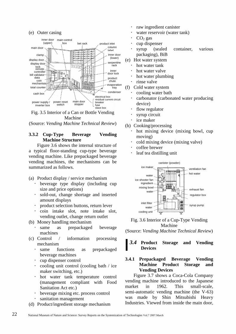
(e) Outer casing
Fig. 3.5 Interior of a Can or Bottle Vending
Machine (Source: Vending Machine Technical Review) 3.3.2 Cup-Type Beverage Vending
Machine Structure Figure 3.6 shows the internal structure of
a typical floor-standing cup-type beverage vending machine. Like prepackaged beverage vending machines, the mechanisms can be summarized as follows. (a) Product display / service mechanism beverage type display (including cup
size and price options) sold-out, change shortage and inserted
amount displays product selection buttons, return lever coin intake slot, note intake slot,
vending outlet, change return outlet (b) Money handling mechanism same as prepackaged beverage
machines (c) Control / information processing
mechanism same functions as prepackaged
beverage machines cup dispenser control cooling unit control (cooling bath / ice
maker switching, etc.) hot water tank temperature control
(management compliant with Food Sanitation Act etc.)
beverage mixing etc. process control sanitation management
(d) Product/ingredient storage mechanism
raw ingredient canister water reservoir (water tank) CO2 gas cup dispenser syrup (sealed container, various
packaging), BiB (e) Hot water system hot water tank hot water valve hot water plumbing rinse valve
(f) Cold water system cooling water bath carbonator (carbonated water producing
device) flow regulator syrup circuit ice maker
(h) Cooking/processing hot mixing device (mixing bowl, cup
moving) cold mixing device (mixing valve) coffee brewer leaf tea distilling unit
Fig. 3.6 Interior of a Cup-Type Vending Machine
(Source: Vending Machine Technical Review)
3.4 Product Storage and Vending Devices
3.4.1 Prepackaged Beverage Vending
Machine Product Storage and Vending Devices
Figure 3.7 shows a Coca-Cola Company vending machine introduced to the Japanese market in 1962. This small-scale, semi-automatic vending machine (the V-63) was made by Shin Mitsubishi Heavy Industries. Viewed from inside the main door,
inner door (upper)
main control box bet rack product inlet
column label inner door
(lower) serpentine
rack
inner door lock
product chute
evaporation tray
condenser electrical box residual current circuit breaker fuse slave box
main door stopper
power reset switch
main door
clamp
display door display door
lock remote
controller bill validator
data coin
mechanism total counter
cash box
power supply / inverter box
ice maker
water ice shooter fan
ingredient mixing bowl
water
inlet filter water
cooling unit
canister (powder)
ventilation fan
hot water
exhaust fan
regulator box
syrup pump
ice maker
water ice shooter fan
ingredient mixing bowl
water
inlet filter water
cooling unit
canister (powder)
ventilation fan hot water
exhaust fan
regulator box
syrup pump
History of the Development of Beverage Vending Machine Technology in Japan 23
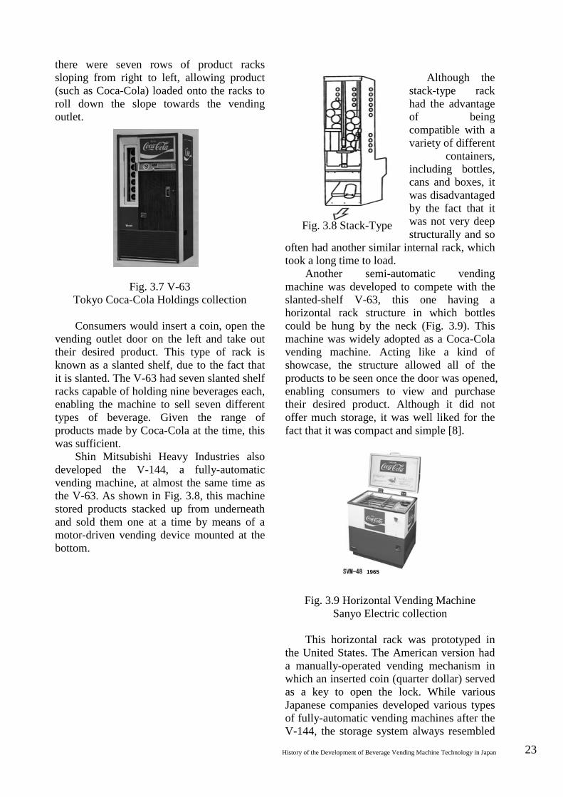
there were seven rows of product racks sloping from right to left, allowing product (such as Coca-Cola) loaded onto the racks to roll down the slope towards the vending outlet.
Fig. 3.7 V-63 Tokyo Coca-Cola Holdings collection
Consumers would insert a coin, open the
vending outlet door on the left and take out their desired product. This type of rack is known as a slanted shelf, due to the fact that it is slanted. The V-63 had seven slanted shelf racks capable of holding nine beverages each, enabling the machine to sell seven different types of beverage. Given the range of products made by Coca-Cola at the time, this was sufficient.
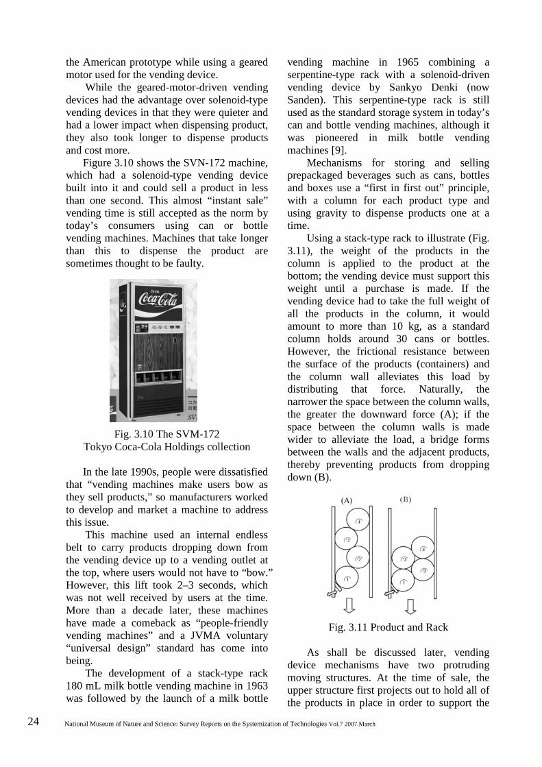
Shin Mitsubishi Heavy Industries also developed the V-144, a fully-automatic vending machine, at almost the same time as the V-63. As shown in Fig. 3.8, this machine stored products stacked up from underneath and sold them one at a time by means of a motor-driven vending device mounted at the bottom.
Although the
stack-type rack had the advantage of being compatible with a variety of different
containers, including bottles, cans and boxes, it was disadvantaged by the fact that it was not very deep structurally and so
often had another similar internal rack, which took a long time to load.
Another semi-automatic vending machine was developed to compete with the slanted-shelf V-63, this one having a horizontal rack structure in which bottles could be hung by the neck (Fig. 3.9). This machine was widely adopted as a Coca-Cola vending machine. Acting like a kind of showcase, the structure allowed all of the products to be seen once the door was opened, enabling consumers to view and purchase their desired product. Although it did not offer much storage, it was well liked for the fact that it was compact and simple [8].
Fig. 3.9 Horizontal Vending Machine
Sanyo Electric collection This horizontal rack was prototyped in
the United States. The American version had a manually-operated vending mechanism in which an inserted coin (quarter dollar) served as a key to open the lock. While various Japanese companies developed various types of fully-automatic vending machines after the V-144, the storage system always resembled
Fig. 3.8 Stack-Type
1965
24 National Museum of Nature and Science: Survey Reports on the Systemization of Technologies Vol.7 2007.March
the American prototype while using a geared motor used for the vending device.
While the geared-motor-driven vending devices had the advantage over solenoid-type vending devices in that they were quieter and had a lower impact when dispensing product, they also took longer to dispense products and cost more.
Figure 3.10 shows the SVN-172 machine, which had a solenoid-type vending device built into it and could sell a product in less than one second. This almost “instant sale” vending time is still accepted as the norm by today’s consumers using can or bottle vending machines. Machines that take longer than this to dispense the product are sometimes thought to be faulty.
Fig. 3.10 The SVM-172 Tokyo Coca-Cola Holdings collection
In the late 1990s, people were dissatisfied
that “vending machines make users bow as they sell products,” so manufacturers worked to develop and market a machine to address this issue.
This machine used an internal endless belt to carry products dropping down from the vending device up to a vending outlet at the top, where users would not have to “bow.” However, this lift took 2–3 seconds, which was not well received by users at the time. More than a decade later, these machines have made a comeback as “people-friendly vending machines” and a JVMA voluntary “universal design” standard has come into being.
The development of a stack-type rack 180 mL milk bottle vending machine in 1963 was followed by the launch of a milk bottle
vending machine in 1965 combining a serpentine-type rack with a solenoid-driven vending device by Sankyo Denki (now Sanden). This serpentine-type rack is still used as the standard storage system in today’s can and bottle vending machines, although it was pioneered in milk bottle vending machines [9].
Mechanisms for storing and selling prepackaged beverages such as cans, bottles and boxes use a “first in first out” principle, with a column for each product type and using gravity to dispense products one at a time.
Using a stack-type rack to illustrate (Fig. 3.11), the weight of the products in the column is applied to the product at the bottom; the vending device must support this weight until a purchase is made. If the vending device had to take the full weight of all the products in the column, it would amount to more than 10 kg, as a standard column holds around 30 cans or bottles. However, the frictional resistance between the surface of the products (containers) and the column wall alleviates this load by distributing that force. Naturally, the narrower the space between the column walls, the greater the downward force (A); if the space between the column walls is made wider to alleviate the load, a bridge forms between the walls and the adjacent products, thereby preventing products from dropping down (B).
Fig. 3.11 Product and Rack
As shall be discussed later, vending device mechanisms have two protruding moving structures. At the time of sale, the upper structure first projects out to hold all of the products in place in order to support the
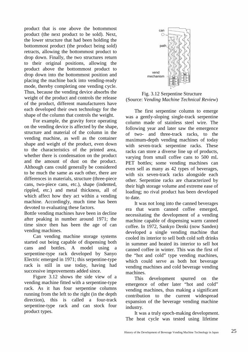
History of the Development of Beverage Vending Machine Technology in Japan 25
product that is one above the bottommost product (the next product to be sold). Next, the lower structure that had been holding the bottommost product (the product being sold) retracts, allowing the bottommost product to drop down. Finally, the two structures return to their original positions, allowing the product above the bottommost product to drop down into the bottommost position and placing the machine back into vending-ready mode, thereby completing one vending cycle. Thus, because the vending device absorbs the weight of the product and controls the release of the product, different manufacturers have each developed their own technology for the shape of the column that controls the weight.
For example, the gravity force operating on the vending device is affected by the shape, structure and material of the column in the vending machine, as well as the container shape and weight of the product, even down to the characteristics of the printed area, whether there is condensation on the product and the amount of dust on the product. Although cans could generally be considered to be much the same as each other, there are differences in materials, structure (three-piece cans, two-piece cans, etc.), shape (indented, rippled, etc.) and metal thickness, all of which affect how they act within a vending machine. Accordingly, much time has been devoted to evaluating these factors. Bottle vending machines have been in decline after peaking in number around 1971; the time since then has been the age of can vending machines.
Can vending machine storage systems started out being capable of dispensing both cans and bottles. A model using a serpentine-type rack developed by Sanyo Electric emerged in 1971; this serpentine-type rack is still in use today, having had successive improvements added since.
Figure 3.12 shows the side view of a vending machine fitted with a serpentine-type rack. As it has four serpentine columns running from the left to the right (in the depth direction), this is called a four-track serpentine-type rack and can stock four product types.
Fig. 3.12 Serpentine Structure
(Source: Vending Machine Technical Review)
The first serpentine column to emerge was a gently-sloping single-track serpentine column made of stainless steel wire. The following year and later saw the emergence of two- and three-track racks, to the maximum-depth vending machines of today with seven-track serpentine racks. These racks can store a diverse line up of products, varying from small coffee cans to 500 mL PET bottles; some vending machines can even sell as many as 42 types of beverages, with six seven-track racks alongside each other. Serpentine racks are characterized by their high storage volume and extreme ease of loading; no rival product has been developed to date.
It was not long into the canned beverages era that warm canned coffee emerged, necessitating the development of a vending machine capable of dispensing warm canned coffee. In 1972, Sankyo Denki (now Sanden) developed a single vending machine that cooled its interior to sell both cold soft drinks in summer and heated its interior to sell hot canned coffee in winter. This was the first of the “hot and cold” type vending machines, which could serve as both hot beverage vending machines and cold beverage vending machines.
This development spurred on the emergence of other later “hot and cold” vending machines, thus making a significant contribution to the current widespread expansion of the beverage vending machine industry.
It was a truly epoch-making development. The heat cycle was tested using lifetime
path
can
vend mechanism

26 National Museum of Nature and Science: Survey Reports on the Systemization of Technologies Vol.7 2007.March
acceleration testing to ensure the motor, solenoid, switches and other functional components, as well as the insulation, lubricant and resin components, could withstand the extreme usage conditions, ranging from low temperatures near 0˚C to high temperatures of 60–70˚C.
In 1974, a new hot and cold can vending machine appeared: one that could sell both hot drinks and cold drinks at the same time. The interior of this machine was divided into two chambers and was configured to be able to (1) warm both chambers, (2) cool both chambers and (3) warm one chamber while cooling the other chamber. By performing operation (1) in winter, operation (2) in summer and operation (3) in spring and fall, this machine could operate optimally all year round. As vending machines began to increase in size, greater variations were possible, increasing from two chambers to three or four chambers.
Figure 3.13 uses an example of a three-chamber machine with six five-track serpentine racks selling 30 kinds of beverage to demonstrate seasonal usage. In this example, the machine switches chambers as follows: in summer everything is cold; in spring there are two hot racks selling ten kinds of hot beverage and four cold racks selling 20 kinds of cold beverage; in fall there are three hot racks and three cold racks each selling 15 kinds of beverage; in winter there are four hot racks selling 20 kinds of beverage and two cold racks selling 10 kinds of beverage (the grid-pattern area in the figure represents the hot chamber).
Fig. 3.13 Example of Chamber Switching
The late 1970s ushered in an era of
diversification in prepackaged beverage
vending machines. Larger takeaway containers (such as 1 or 2 liter containers) started being sold in vending machines; vending machines started being used year round with the advent of hot beverage capability; beverage manufacturers started diversifying product containers for branding tactics; intensified product (beverage) competition meant an increased variety of beverage content; the use of PET bottles and other types of containers meant that vending machines had to increase the number of stocked products (multi-selection capability); product content volume increased (larger sizes); special shaped containers had to be accommodated. These changes resulted in successive new developments in racks and vending devices.
The main storage/vending devices developed included the chain elevator system (also called a chain rack), the conveyor system, the boxed container stack system and the spiral system.
Figure 3.14 shows the storage method and vending mechanism for the chain elevator system. The products are stored individually on a product shelf that moves up and down along the column wall; at the time of sale, the upper vend motor moves the product shelf attached to the chain to the lower drum, which then slowly rotates to drop the product into the vending outlet. This system is characterized in that it can be used to dispense large, heavy products without any Impact shock.
summer spring fall winter
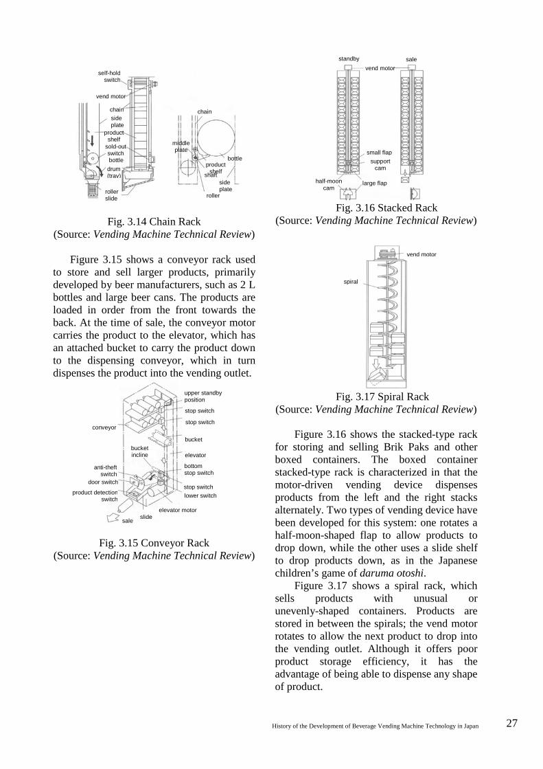
History of the Development of Beverage Vending Machine Technology in Japan 27
Fig. 3.14 Chain Rack
(Source: Vending Machine Technical Review)
Figure 3.15 shows a conveyor rack used to store and sell larger products, primarily developed by beer manufacturers, such as 2 L bottles and large beer cans. The products are loaded in order from the front towards the back. At the time of sale, the conveyor motor carries the product to the elevator, which has an attached bucket to carry the product down to the dispensing conveyor, which in turn dispenses the product into the vending outlet.
Fig. 3.15 Conveyor Rack (Source: Vending Machine Technical Review)
Fig. 3.16 Stacked Rack (Source: Vending Machine Technical Review)
Fig. 3.17 Spiral Rack (Source: Vending Machine Technical Review)
Figure 3.16 shows the stacked-type rack for storing and selling Brik Paks and other boxed containers. The boxed container stacked-type rack is characterized in that the motor-driven vending device dispenses products from the left and the right stacks alternately. Two types of vending device have been developed for this system: one rotates a half-moon-shaped flap to allow products to drop down, while the other uses a slide shelf to drop products down, as in the Japanese children’s game of daruma otoshi.
Figure 3.17 shows a spiral rack, which sells products with unusual or unevenly-shaped containers. Products are stored in between the spirals; the vend motor rotates to allow the next product to drop into the vending outlet. Although it offers poor product storage efficiency, it has the advantage of being able to dispense any shape of product.
self-hold switch
vend motor
chain side plate
product shelf
sold-out switch bottle
drum (tray)
roller slide
middle plate
product shelf
chain
bottle
roller
side plate
shaft
conveyor
anti-theft switch
door switch
product detection switch
bucket incline
upper standby position
stop switch
stop switch
elevator
bottom stop switch
stop switch lower switch
elevator motor
bucket
slide sale
vend motor
spiral
standby vend motor
sale
support cam
half-moon cam
large flap
small flap

28 National Museum of Nature and Science: Survey Reports on the Systemization of Technologies Vol.7 2007.March
Operation of the vending device Figure 3.18 shows the operation of the
vending device for a serpentine rack (for example). In standby mode, the bottommost product is supported by a pedal. In sale mode, a current passes through a solenoid, pulling up the solenoid plunger and retracting the pedal attached to it, allowing the product supported by the pedal to drop down; at the same time, the upper pedal protrudes out into the pathway to support the next product. When the current is switched off, a spring causes the solenoid plunger to return to its former position in standby mode for the next product.
The current passes through the solenoid for around 0.3–0.5 seconds; during this time, the product is dispensed into the vending outlet.
Fig. 3.18 Vending Device (Source: Vending Machine Technical Review) 3.4.2 Cup-Type Beverage Vending
Machine Ingredient Storage and Vending Mechanisms
As previously discussed, cup-type beverage vending machines prepare the beverage internally and pour it into a container. They are fitted with ingredient storage, hot water system circuits, refrigeration circuits, distillation equipment, mixing equipment and other equipment to ensure hygienic operation. (1) Cold beverages
Figure 3.19 shows a preparation process for carbonated drinks with ice. The product (cold beverage) is made up of tap water, carbon dioxide gas, syrup and a paper cup. The following provides an outline of how these constituent materials are stored. The tap water is stored in a primary water reservoir; some of it is then (1) passed through a cooling water bath into an ice maker and then stored in an ice box in the form of ice, while some of it is (2) pressurized with a pump and
sprayed into a carbonator and then stored in the form of carbonated water. The carbon dioxide gas is stored in a bomb; some of it is (1) used to pressurize the syrup container, while some of it is (2) sent to the carbonator to create carbonated water. The syrup is kept within the machine in a sealed container and pressurized with the carbon dioxide gas. The paper cups are stored in a cup dispenser.
Fig. 3.19 Carbonated Beverage Manufacturing Process
(Source: Vending Machine Technical Review)
The beverage vending process involves the cup being dropped onto the stage (the vending outlet), then the ice dropping into the cup from the ice box, followed by the pouring of the syrup and the carbonated water and finishing with the beverage being mixed in the cup by means of the force of the water flow. Everything in the carbonator, the syrup and the diluting water are cooled in the cooling tank by means of a heat exchanger (cooling coil) and poured into the cup. The following provides an outline of each element. ○1 Water reservoir
Also called the cistern, the water reservoir is the primary storage tank for the tap water. This mechanism in vending machines that are directly connected to a water supply satisfies the criteria imposed by the Water Supply Act as a countermeasure against backflow. Figure 3.20 shows a cistern with the
stand sale return standby sale return
automatic water supply valve
water pump
water supply
reservoir
cup storage
water
ice syrup
low
pre
ssur
e ca
rbon
dio
xide
gas
wat
er
cup carbonated water
cool
ing
wat
er b
ath
water
carb
onat
ed
wat
er
water
cool
er
syrup vending outlet
drainage
drainage container
high pressure carbon dioxide gas
carb
on d
ioxi
de g
as b
omb
syrup container
ice maker

History of the Development of Beverage Vending Machine Technology in Japan 29
cover open; the water supply is controlled by a water-level-detecting float with a valve attached.
Fig. 3.20 Cistern (Source: Vending Machine Technical Review) ○2 Water bath
The water bath cools the syrup and carbonated water and keeps them cool. The water bath has a built-in cooling cycle evaporator that forms ice around it; the cooling water is maintained at around 0˚C using an agitator.
Fig. 3.21 Ice Bank Control
(Source: Vending Machine Technical
Review)
Fig. 3.22 Water Bath Structure
(Source: Vending Machine Technical
Review)
When ice levels are low in the water bath, the cold beverage vending capacity reduces; when ice levels are too high, the syrup and the diluting water in the water bath will also freeze. The ice bank control operation prevents this. This control mechanism uses a switching circuit acting on the difference in electrical resistance (conductivity) between the ice and the water when there is too much ice. Figure 3.21 shows an example of how the electrodes can be arranged in the water bath.
As shown in Fig. 3.22, the cooling water bath is fitted with the carbonator and the piping for the syrup and diluting
water circuits. An agitator agitates the cooling water for rapid heat exchange. The circuit shown in bold lines is the coolant circuit for the cooling cycle. As the coolant changes from liquid to gas in the evaporator, ice is created as the heat is taken out of the surrounding area. The thickness of this ice is regulated to maintain the temperature of the coolant at around 0˚C.
○3 Carbonator The carbonator is a pressure vessel
that produces carbonated water by mixing carbon dioxide gas with water. When high-pressure water is injected through the water pump into the high-pressure gas from the gas bomb, the carbon dioxide gas dissolves in the water to form carbonated water. The carbonator has a water level switch, a check valve and a safety valve (see Fig. 3.23).
Fig. 3.23 Carbonator (Source: Vending Machine Technical Review)
○4 Cup dispenser A general term for cup storing and
dispensing devices [10]. There are six types of cups used in
vending machines: 5, 6.5, 7, 9, 12 and 16 ounces. Cup dispensers normally offer up to three of these types.
reservoir cover
hooks
water reservoir
outlet pipe
coupler
ring nut
float switch
check valve
plate
safety valve
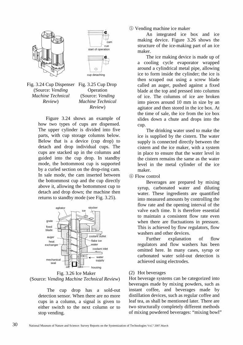
30 National Museum of Nature and Science: Survey Reports on the Systemization of Technologies Vol.7 2007.March
Fig. 3.24 Cup Dispenser (Source: Vending
Machine Technical Review)
Fig. 3.25 Cup Drop Operation
(Source: Vending Machine Technical
Review)
Figure 3.24 shows an example of how two types of cups are dispensed. The upper cylinder is divided into five parts, with cup storage columns below. Below that is a device (cup drop) to detach and drop individual cups. The cups are stacked up in the columns and guided into the cup drop. In standby mode, the bottommost cup is supported by a curled section on the drop-ring cam. In sale mode, the cam inserted between the bottommost cup and the cup directly above it, allowing the bottommost cup to detach and drop down; the machine then returns to standby mode (see Fig. 3.25).
Fig. 3.26 Ice Maker (Source: Vending Machine Technical Review)
The cup drop has a sold-out detection sensor. When there are no more cups in a column, a signal is given to either switch to the next column or to stop vending.
○5 Vending machine ice maker An integrated ice box and ice
making device. Figure 3.26 shows the structure of the ice-making part of an ice maker.
The ice making device is made up of a cooling cycle evaporator wrapped around a cylindrical metal pipe, allowing ice to form inside the cylinder; the ice is then scraped out using a screw blade called an auger, pushed against a fixed blade at the top and pressed into columns of ice. The columns of ice are broken into pieces around 10 mm in size by an agitator and then stored in the ice box. At the time of sale, the ice from the ice box slides down a chute and drops into the cup.
The drinking water used to make the ice is supplied by the cistern. The water supply is connected directly between the cistern and the ice maker, with a system in place to ensure that the water level in the cistern remains the same as the water level in the metal cylinder of the ice maker.
○6 Flow control Beverages are prepared by mixing
syrup, carbonated water and diluting water. These ingredients are quantified into measured amounts by controlling the flow rate and the opening interval of the valve each time. It is therefore essential to maintain a consistent flow rate even when there are fluctuations in pressure. This is achieved by flow regulators, flow washers and other devices.
Further explanation of flow regulators and flow washers has been omitted here. In many cases, syrup or carbonated water sold-out detection is achieved using electrodes.
(2) Hot beverages Hot beverage systems can be categorized into beverages made by mixing powders, such as instant coffee, and beverages made by distillation devices, such as regular coffee and leaf tea, as shall be mentioned later. There are two structurally completely different methods of mixing powdered beverages: “mixing bowl”
stocker agitator ice
grate
fixed blade
auger heat
exchanger
coolant outlet flake ice water
coolant inlet
mechanical seal
water supply
housing
cam cup
start of operation
cup detaching
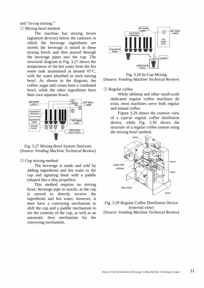
History of the Development of Beverage Vending Machine Technology in Japan 31
and “in-cup mixing.” ○1 Mixing bowl method
The machine has mixing bowls (agitation devices) below the canisters in which the beverage ingredients are stored; the beverage is mixed in these mixing bowls and then poured through the beverage pipes into the cup. The structural diagram in Fig. 3.27 shows the temperature of the hot water from the hot water tank maintained at around 95˚C, with the water plumbed to each mixing bowl. As shown in the diagram, the coffee, sugar and cream have a combined bowl, while the other ingredients have their own separate bowls.
Fig. 3.27 Mixing Bowl System Structure (Source: Vending Machine Technical Review) ○2 Cup mixing method
The beverage is made and sold by adding ingredients and hot water to the cup and agitating them with a paddle (shaped like a ship propeller).
This method requires no mixing bowl, beverage pipe or nozzle, as the cup is moved to directly receive the ingredients and hot water; however, it does have a conveying mechanism to shift the cup and a paddle mechanism to stir the contents of the cup, as well as an automatic door mechanism for the conveying mechanism.
Fig. 3.28 In-Cup Mixing (Source: Vending Machine Technical Review) ○3 Regular coffee
While tabletop and other small-scale dedicated regular coffee machines do exist, most machines serve both regular and instant coffee.
Figure 3.29 shows the exterior view of a typical regular coffee distillation device, while Fig. 3.30 shows the structure of a regular coffee system using the mixing bowl method.
Fig. 3.29 Regular Coffee Distillation Device (external view)
(Source: Vending Machine Technical Review)
ingredient canisters
hot water pipes
ingredient slide
mixing bowls
hot water valve
hot water tank
beverage pipe/nozzle
hot water pipe
ingredient canisters
ingredient slides
hot water valve
hot water tank
paddle
preparation area
valve
paper filter cylinder
filter block
drum
roller
lever
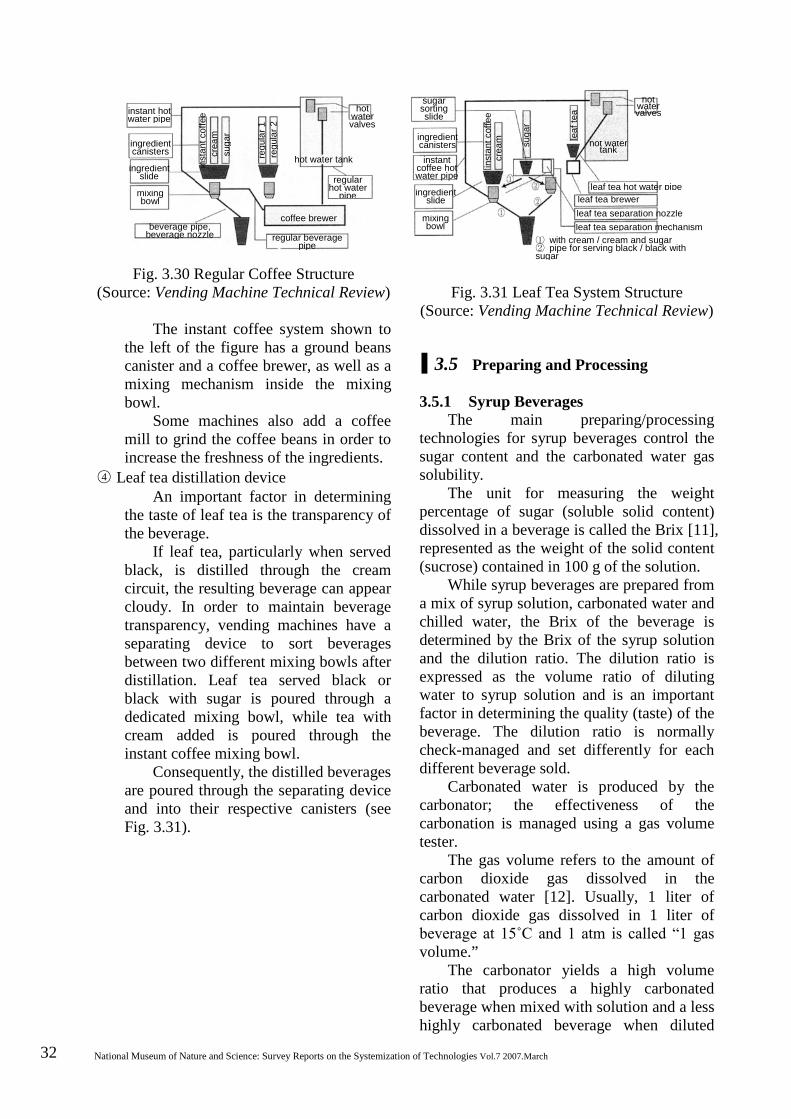
32 National Museum of Nature and Science: Survey Reports on the Systemization of Technologies Vol.7 2007.March
sugar sorting slide
ingredient canisters instant
coffee hot water pipe
ingredient slide
mixing bowl
hot water valves
hot water tank
leaf tea hot water pipe leaf tea brewer leaf tea separation nozzle leaf tea separation mechanism
① with cream / cream and sugar ② pipe for serving black / black with sugar
leaf
tea
suga
r
crea
m
inst
ant c
offe
e instant hot water pipe
ingredient canisters
ingredient slide
mixing bowl
beverage pipe, beverage nozzle
hot water valves
hot water tank
regular hot water
pipe
coffee brewer
regular beverage pipe
inst
ant c
offe
e cr
eam
su
gar
regu
lar 1
re
gula
r 2
Fig. 3.30 Regular Coffee Structure (Source: Vending Machine Technical Review)
The instant coffee system shown to the left of the figure has a ground beans canister and a coffee brewer, as well as a mixing mechanism inside the mixing bowl.
Some machines also add a coffee mill to grind the coffee beans in order to increase the freshness of the ingredients.
○4 Leaf tea distillation device An important factor in determining
the taste of leaf tea is the transparency of the beverage.
If leaf tea, particularly when served black, is distilled through the cream circuit, the resulting beverage can appear cloudy. In order to maintain beverage transparency, vending machines have a separating device to sort beverages between two different mixing bowls after distillation. Leaf tea served black or black with sugar is poured through a dedicated mixing bowl, while tea with cream added is poured through the instant coffee mixing bowl.
Consequently, the distilled beverages are poured through the separating device and into their respective canisters (see Fig. 3.31).
Fig. 3.31 Leaf Tea System Structure (Source: Vending Machine Technical Review)
3.5 Preparing and Processing 3.5.1 Syrup Beverages
The main preparing/processing technologies for syrup beverages control the sugar content and the carbonated water gas solubility.
The unit for measuring the weight percentage of sugar (soluble solid content) dissolved in a beverage is called the Brix [11], represented as the weight of the solid content (sucrose) contained in 100 g of the solution.
While syrup beverages are prepared from a mix of syrup solution, carbonated water and chilled water, the Brix of the beverage is determined by the Brix of the syrup solution and the dilution ratio. The dilution ratio is expressed as the volume ratio of diluting water to syrup solution and is an important factor in determining the quality (taste) of the beverage. The dilution ratio is normally check-managed and set differently for each different beverage sold.
Carbonated water is produced by the carbonator; the effectiveness of the carbonation is managed using a gas volume tester.
The gas volume refers to the amount of carbon dioxide gas dissolved in the carbonated water [12]. Usually, 1 liter of carbon dioxide gas dissolved in 1 liter of beverage at 15˚C and 1 atm is called “1 gas volume.”
The carbonator yields a high volume ratio that produces a highly carbonated beverage when mixed with solution and a less highly carbonated beverage when diluted
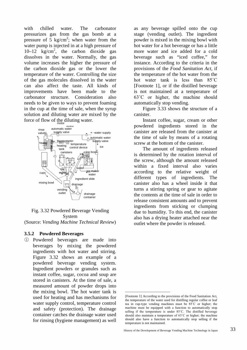
History of the Development of Beverage Vending Machine Technology in Japan 33
with chilled water. The carbonator pressurizes gas from the gas bomb at a pressure of 5 kg/cm2; when water from the water pump is injected in at a high pressure of 10–12 kg/cm2, the carbon dioxide gas dissolves in the water. Normally, the gas volume increases the higher the pressure of the carbon dioxide gas or the lower the temperature of the water. Controlling the size of the gas molecules dissolved in the water can also affect the taste. All kinds of improvements have been made to the carbonator structure. Consideration also needs to be given to ways to prevent foaming in the cup at the time of sale, when the syrup solution and diluting water are mixed by the force of flow of the diluting water.
Fig. 3.32 Powdered Beverage Vending
System (Source: Vending Machine Technical Review) 3.5.2 Powdered Beverages ○1 Powdered beverages are made into
beverages by mixing the powdered ingredients with hot water and stirring. Figure 3.32 shows an example of a powdered beverage vending system. Ingredient powders or granules such as instant coffee, sugar, cocoa and soup are stored in canisters. At the time of sale, a measured amount of powder drops into the mixing bowl. The hot water tank is used for heating and has mechanisms for water supply control, temperature control and safety (protection). The drainage container catches the drainage water used for rinsing (hygiene management) as well
as any beverage spilled onto the cup stage (vending outlet). The ingredient powder is mixed in the mixing bowl with hot water for a hot beverage or has a little more water and ice added for a cold beverage such as “iced coffee,” for instance. According to the criteria in the provisions of the Food Sanitation Act, if the temperature of the hot water from the hot water tank is less than 85˚C [Footnote 1], or if the distilled beverage is not maintained at a temperature of 63˚C or higher, the machine should automatically stop vending.
Figure 3.33 shows the structure of a canister.
Instant coffee, sugar, cream or other powdered ingredients stored in the canister are released from the canister at the time of sale by means of a rotating screw at the bottom of the canister.
The amount of ingredients released is determined by the rotation interval of the screw, although the amount released within a fixed interval also varies according to the relative weight of different types of ingredients. The canister also has a wheel inside it that turns a stirring spring or gear to agitate the contents at the time of sale in order to release consistent amounts and to prevent ingredients from sticking or clumping due to humidity. To this end, the canister also has a drying heater attached near the outlet where the powder is released.
[Footnote 1] According to the provisions of the Food Sanitation Act, the temperature of the water used for distilling regular coffee or leaf tea in cup-type vending machines must be 85˚C or higher; the machine must be equipped with a function to automatically stop selling if the temperature is under 85˚C. The distilled beverage should also maintain a temperature of 63˚C or higher; the machine should also have a function to automatically stop selling if the temperature is not maintained.
motor motor
automatic water supply valve
rinse valve
thermometer heater temperature control device heating
tank canisters
ice
ice box
water supply
automatic water supply valve
water
hot water
ice
ice maker water
hot water
ingredient slide
cups
mixing bowl
vending outlet
drainage
drainage container
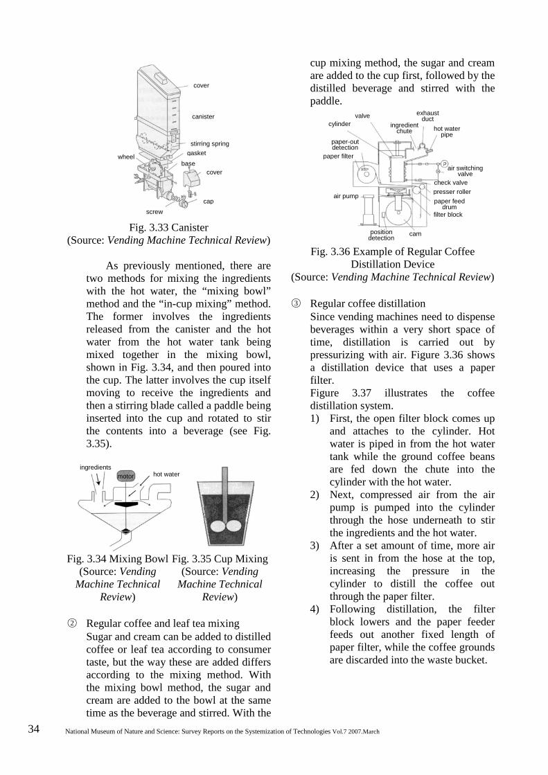
34 National Museum of Nature and Science: Survey Reports on the Systemization of Technologies Vol.7 2007.March
valve cylinder ingredient
chute
exhaust duct
hot water pipe
paper-out detection
paper filter
air pump
air switching valve
check valve presser roller paper feed
drum filter block
position detection cam
cover
canister
wheel
stirring spring gasket
base cover
cap screw
Fig. 3.33 Canister (Source: Vending Machine Technical Review)
As previously mentioned, there are
two methods for mixing the ingredients with the hot water, the “mixing bowl” method and the “in-cup mixing” method. The former involves the ingredients released from the canister and the hot water from the hot water tank being mixed together in the mixing bowl, shown in Fig. 3.34, and then poured into the cup. The latter involves the cup itself moving to receive the ingredients and then a stirring blade called a paddle being inserted into the cup and rotated to stir the contents into a beverage (see Fig. 3.35).
Fig. 3.34 Mixing Bowl (Source: Vending
Machine Technical Review)
Fig. 3.35 Cup Mixing (Source: Vending
Machine Technical Review)
○2 Regular coffee and leaf tea mixing
Sugar and cream can be added to distilled coffee or leaf tea according to consumer taste, but the way these are added differs according to the mixing method. With the mixing bowl method, the sugar and cream are added to the bowl at the same time as the beverage and stirred. With the
cup mixing method, the sugar and cream are added to the cup first, followed by the distilled beverage and stirred with the paddle.
Fig. 3.36 Example of Regular Coffee Distillation Device
(Source: Vending Machine Technical Review) ○3 Regular coffee distillation
Since vending machines need to dispense beverages within a very short space of time, distillation is carried out by pressurizing with air. Figure 3.36 shows a distillation device that uses a paper filter. Figure 3.37 illustrates the coffee distillation system. 1) First, the open filter block comes up
and attaches to the cylinder. Hot water is piped in from the hot water tank while the ground coffee beans are fed down the chute into the cylinder with the hot water.
2) Next, compressed air from the air pump is pumped into the cylinder through the hose underneath to stir the ingredients and the hot water.
3) After a set amount of time, more air is sent in from the hose at the top, increasing the pressure in the cylinder to distill the coffee out through the paper filter.
4) Following distillation, the filter block lowers and the paper feeder feeds out another fixed length of paper filter, while the coffee grounds are discarded into the waste bucket.
ingredients hot water motor
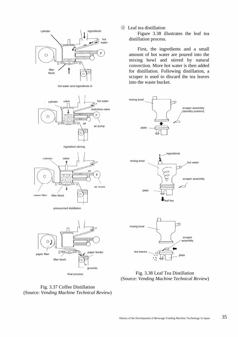
History of the Development of Beverage Vending Machine Technology in Japan 35
mixing bowl
scraper assembly (standby position)
plate
ingredients
mixing bowl hot water
scraper assembly
plate
leaf tea
mixing bowl
scraper assembly
tea leaves plate
Fig. 3.37 Coffee Distillation
(Source: Vending Machine Technical Review)
○4 Leaf tea distillation Figure 3.38 illustrates the leaf tea
distillation process.
First, the ingredients and a small amount of hot water are poured into the mixing bowl and stirred by natural convection. More hot water is then added for distillation. Following distillation, a scraper is used to discard the tea leaves into the waste bucket.
Fig. 3.38 Leaf Tea Distillation (Source: Vending Machine Technical Review)
cylinder ingredients
hot water
filter block
hot water and ingredients in
cylinder valve hot water
switching valve
air pump air
ingredient stirring
cylinder valve
air
air pump
paper filter filter block
pressurized distillation
paper feeder
grounds
final process
filter block
paper filter
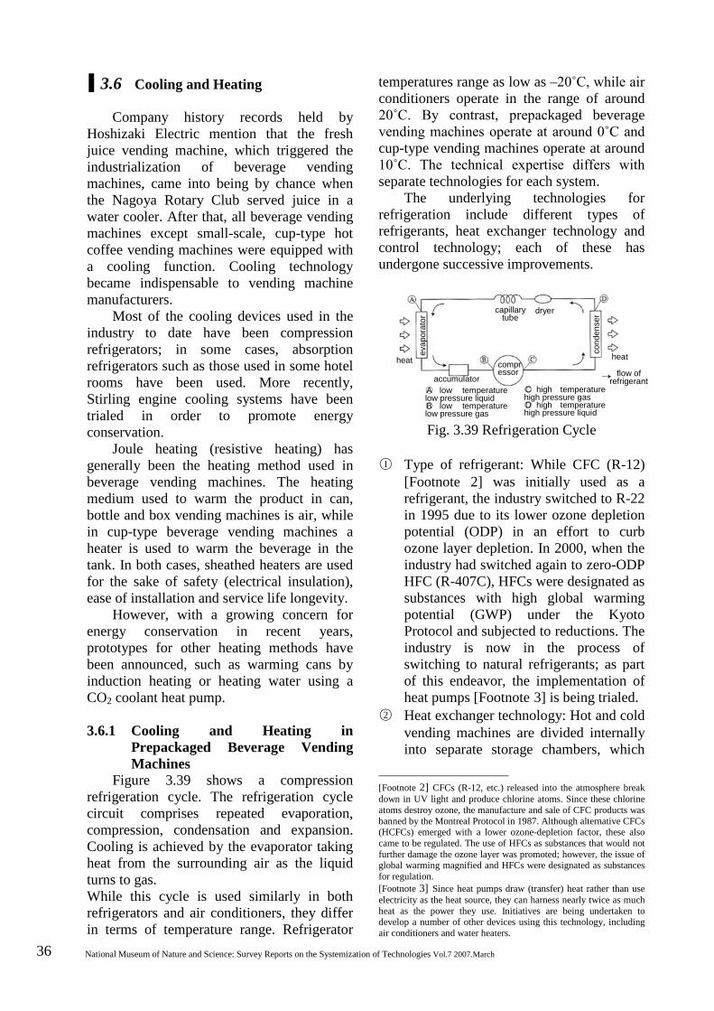
36 National Museum of Nature and Science: Survey Reports on the Systemization of Technologies Vol.7 2007.March
3.6 Cooling and Heating
Company history records held by Hoshizaki Electric mention that the fresh juice vending machine, which triggered the industrialization of beverage vending machines, came into being by chance when the Nagoya Rotary Club served juice in a water cooler. After that, all beverage vending machines except small-scale, cup-type hot coffee vending machines were equipped with a cooling function. Cooling technology became indispensable to vending machine manufacturers.
Most of the cooling devices used in the industry to date have been compression refrigerators; in some cases, absorption refrigerators such as those used in some hotel rooms have been used. More recently, Stirling engine cooling systems have been trialed in order to promote energy conservation.
Joule heating (resistive heating) has generally been the heating method used in beverage vending machines. The heating medium used to warm the product in can, bottle and box vending machines is air, while in cup-type beverage vending machines a heater is used to warm the beverage in the tank. In both cases, sheathed heaters are used for the sake of safety (electrical insulation), ease of installation and service life longevity.
However, with a growing concern for energy conservation in recent years, prototypes for other heating methods have been announced, such as warming cans by induction heating or heating water using a CO2 coolant heat pump.
3.6.1 Cooling and Heating in Prepackaged Beverage Vending Machines
Figure 3.39 shows a compression refrigeration cycle. The refrigeration cycle circuit comprises repeated evaporation, compression, condensation and expansion. Cooling is achieved by the evaporator taking heat from the surrounding air as the liquid turns to gas. While this cycle is used similarly in both refrigerators and air conditioners, they differ in terms of temperature range. Refrigerator
temperatures range as low as –20˚C, while air conditioners operate in the range of around 20˚C. By contrast, prepackaged beverage vending machines operate at around 0˚C and cup-type vending machines operate at around 10˚C. The technical expertise differs with separate technologies for each system.
The underlying technologies for refrigeration include different types of refrigerants, heat exchanger technology and control technology; each of these has undergone successive improvements.
Fig. 3.39 Refrigeration Cycle ○1 Type of refrigerant: While CFC (R-12)
[Footnote 2] was initially used as a refrigerant, the industry switched to R-22 in 1995 due to its lower ozone depletion potential (ODP) in an effort to curb ozone layer depletion. In 2000, when the industry had switched again to zero-ODP HFC (R-407C), HFCs were designated as substances with high global warming potential (GWP) under the Kyoto Protocol and subjected to reductions. The industry is now in the process of switching to natural refrigerants; as part of this endeavor, the implementation of heat pumps [Footnote 3] is being trialed.
○2 Heat exchanger technology: Hot and cold vending machines are divided internally into separate storage chambers, which
[Footnote 2] CFCs (R-12, etc.) released into the atmosphere break down in UV light and produce chlorine atoms. Since these chlorine atoms destroy ozone, the manufacture and sale of CFC products was banned by the Montreal Protocol in 1987. Although alternative CFCs (HCFCs) emerged with a lower ozone-depletion factor, these also came to be regulated. The use of HFCs as substances that would not further damage the ozone layer was promoted; however, the issue of global warming magnified and HFCs were designated as substances for regulation. [Footnote 3] Since heat pumps draw (transfer) heat rather than use electricity as the heat source, they can harness nearly twice as much heat as the power they use. Initiatives are being undertaken to develop a number of other devices using this technology, including air conditioners and water heaters.
capillary tube
dryer
heat cond
ense
r
accumulator
compressor flow of
refrigerant ○A low temperature low pressure liquid ○B low temperature low pressure gas
evap
orat
or
heat
○C high temperature high pressure gas ○D high temperature high pressure liquid
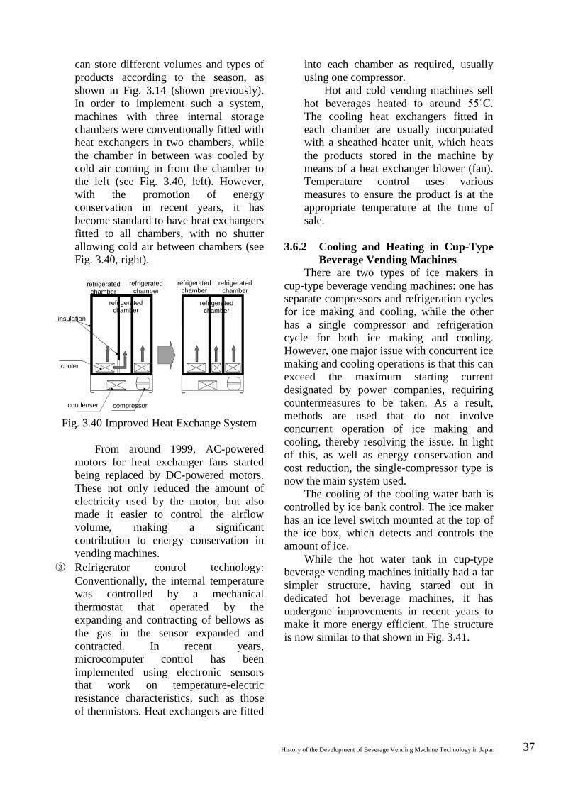
History of the Development of Beverage Vending Machine Technology in Japan 37
can store different volumes and types of products according to the season, as shown in Fig. 3.14 (shown previously). In order to implement such a system, machines with three internal storage chambers were conventionally fitted with heat exchangers in two chambers, while the chamber in between was cooled by cold air coming in from the chamber to the left (see Fig. 3.40, left). However, with the promotion of energy conservation in recent years, it has become standard to have heat exchangers fitted to all chambers, with no shutter allowing cold air between chambers (see Fig. 3.40, right).
Fig. 3.40 Improved Heat Exchange System
From around 1999, AC-powered motors for heat exchanger fans started being replaced by DC-powered motors. These not only reduced the amount of electricity used by the motor, but also made it easier to control the airflow volume, making a significant contribution to energy conservation in vending machines.
○3 Refrigerator control technology: Conventionally, the internal temperature was controlled by a mechanical thermostat that operated by the expanding and contracting of bellows as the gas in the sensor expanded and contracted. In recent years, microcomputer control has been implemented using electronic sensors that work on temperature-electric resistance characteristics, such as those of thermistors. Heat exchangers are fitted
into each chamber as required, usually using one compressor.
Hot and cold vending machines sell hot beverages heated to around 55˚C. The cooling heat exchangers fitted in each chamber are usually incorporated with a sheathed heater unit, which heats the products stored in the machine by means of a heat exchanger blower (fan). Temperature control uses various measures to ensure the product is at the appropriate temperature at the time of sale.
3.6.2 Cooling and Heating in Cup-Type
Beverage Vending Machines There are two types of ice makers in
cup-type beverage vending machines: one has separate compressors and refrigeration cycles for ice making and cooling, while the other has a single compressor and refrigeration cycle for both ice making and cooling. However, one major issue with concurrent ice making and cooling operations is that this can exceed the maximum starting current designated by power companies, requiring countermeasures to be taken. As a result, methods are used that do not involve concurrent operation of ice making and cooling, thereby resolving the issue. In light of this, as well as energy conservation and cost reduction, the single-compressor type is now the main system used.
The cooling of the cooling water bath is controlled by ice bank control. The ice maker has an ice level switch mounted at the top of the ice box, which detects and controls the amount of ice.
While the hot water tank in cup-type beverage vending machines initially had a far simpler structure, having started out in dedicated hot beverage machines, it has undergone improvements in recent years to make it more energy efficient. The structure is now similar to that shown in Fig. 3.41.
refrigerated chamber
refrigerated chamber
refrigerated chamber
refrigerated chamber
refrigerated chamber
refrigerated chamber
insulation
cooler
condenser compressor

38 National Museum of Nature and Science: Survey Reports on the Systemization of Technologies Vol.7 2007.March
Fig. 3.41 Hot Water Tank Structure
(provided by Fuji Electric Retail Systems)
The tank has two heaters and is divided into a high-temperature section and a preheating section. Water feeding in from the cistern enters at the bottom and flows out from the hot water valve at the top. 3.6.3 Beverage Vending Machine
Energy Conservation Initiatives Can and bottle vending machines were
designated as specified devices [Footnote 4] under the Energy Conservation Law in 2001, achieving an energy saving of around 37% within five years.
The following outlines the developments in energy-conservation-related technologies over the past decade. ○1 Main improvements to prepackaged
beverage vending machines (1) Heat exchanger: enlarged heat
dissipation area with internally-grooved pipes
(2) Countermeasures to prevent radiator clogging
(3) Adoption of DC motors (4) Internal airflow rectification (5) Vacuum insulation in partitions
between hot and cold chambers (6) Inner doors for loading (7) Fluorescent inverter lighting, 50%
reduction in illumination (8) Separate base plate structure
[Footnote 4] The Law Concerning the Rational Use of Energy (the Energy Conservation Law for short) was enacted in 1979 to promote energy conservation in factories, buildings and machinery and equipment. Vending machines were designated as specified devices in 2001. Anticipating further improvements in power consumption by leading products in the base year, improvement initiatives were undertaken with these as target values, resulting in a 37% reduction in power consumption against the base year.
○2 Main improvements to cup-type beverage vending machines
(1) Smaller hot water tank (capacity) (2) Adoption of instant heating methods
(partial) (3) Adoption of DC motors (4) Fluorescent inverter lighting,
dimming (5) Motion detector illumination
(partial) (6) Learned energy conservation
(conserving energy based on sales information)
3.7 Money Handling Mechanisms and Controls
In the beverage and tobacco vending machine market, devices that process coins are called coin mechanisms (Fig. 3.42, right), while devices that process bills are called bill validators (Fig. 3.42, left).
Coin mechanisms are integrated units combining (1) a coin validation device and (2) a change storage/payout device. Similarly, bill validators are integrated units combining (1) a bill validation device and (2) a bill storage device. A major feature of these money handling devices is their progress towards industry standardization; these units are the focus of technology competition between manufacturers, with plans for standardization at manufacturer level.
Fig. 3.42 Standardized Coin Mechanism and Bill Validator
(provided by Nippon Conlux)
high water level switch
low water level switch
boil prevention thermo
float
overflow pipe
main heater hot water
valves
sub heater
rinse valve water inlet
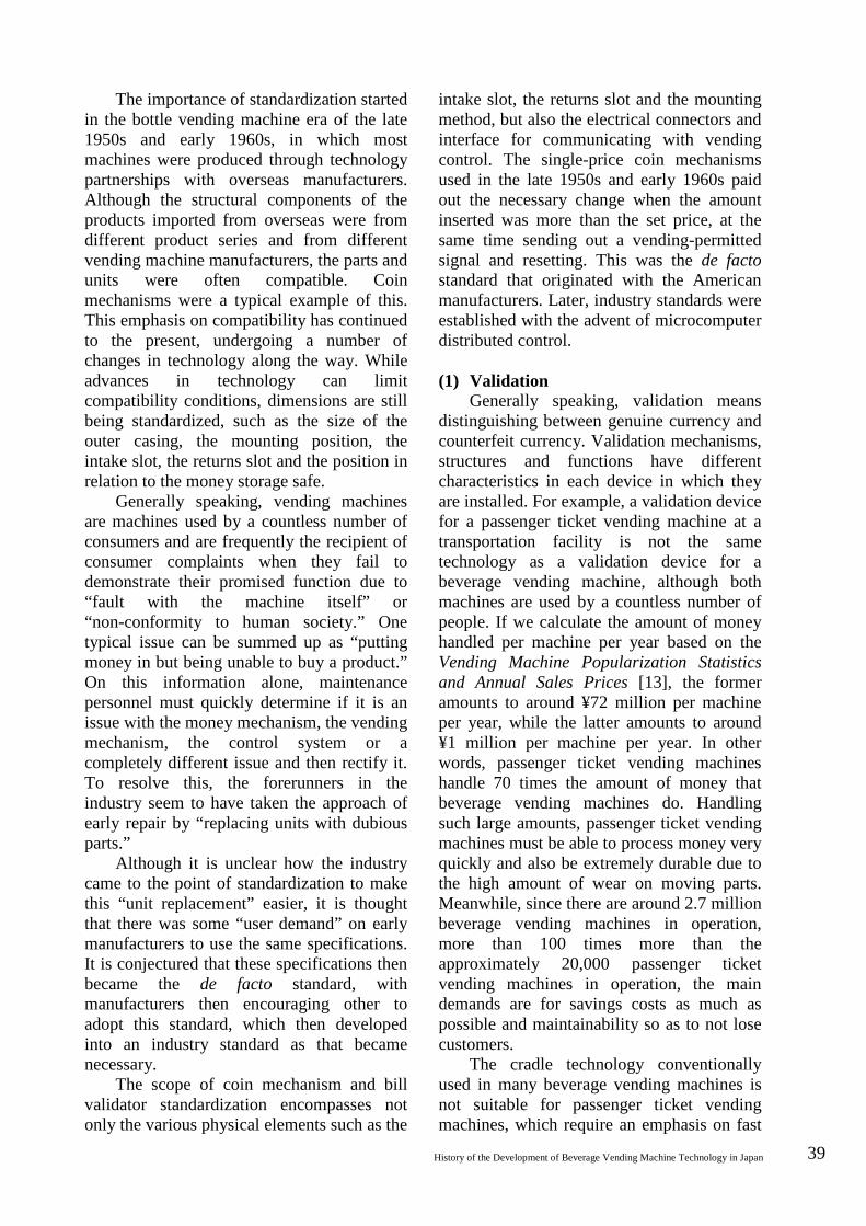
History of the Development of Beverage Vending Machine Technology in Japan 39
The importance of standardization started in the bottle vending machine era of the late 1950s and early 1960s, in which most machines were produced through technology partnerships with overseas manufacturers. Although the structural components of the products imported from overseas were from different product series and from different vending machine manufacturers, the parts and units were often compatible. Coin mechanisms were a typical example of this. This emphasis on compatibility has continued to the present, undergoing a number of changes in technology along the way. While advances in technology can limit compatibility conditions, dimensions are still being standardized, such as the size of the outer casing, the mounting position, the intake slot, the returns slot and the position in relation to the money storage safe.
Generally speaking, vending machines are machines used by a countless number of consumers and are frequently the recipient of consumer complaints when they fail to demonstrate their promised function due to “fault with the machine itself” or “non-conformity to human society.” One typical issue can be summed up as “putting money in but being unable to buy a product.” On this information alone, maintenance personnel must quickly determine if it is an issue with the money mechanism, the vending mechanism, the control system or a completely different issue and then rectify it. To resolve this, the forerunners in the industry seem to have taken the approach of early repair by “replacing units with dubious parts.”
Although it is unclear how the industry came to the point of standardization to make this “unit replacement” easier, it is thought that there was some “user demand” on early manufacturers to use the same specifications. It is conjectured that these specifications then became the de facto standard, with manufacturers then encouraging other to adopt this standard, which then developed into an industry standard as that became necessary.
The scope of coin mechanism and bill validator standardization encompasses not only the various physical elements such as the
intake slot, the returns slot and the mounting method, but also the electrical connectors and interface for communicating with vending control. The single-price coin mechanisms used in the late 1950s and early 1960s paid out the necessary change when the amount inserted was more than the set price, at the same time sending out a vending-permitted signal and resetting. This was the de facto standard that originated with the American manufacturers. Later, industry standards were established with the advent of microcomputer distributed control. (1) Validation
Generally speaking, validation means distinguishing between genuine currency and counterfeit currency. Validation mechanisms, structures and functions have different characteristics in each device in which they are installed. For example, a validation device for a passenger ticket vending machine at a transportation facility is not the same technology as a validation device for a beverage vending machine, although both machines are used by a countless number of people. If we calculate the amount of money handled per machine per year based on the Vending Machine Popularization Statistics and Annual Sales Prices [13], the former amounts to around ¥72 million per machine per year, while the latter amounts to around ¥1 million per machine per year. In other words, passenger ticket vending machines handle 70 times the amount of money that beverage vending machines do. Handling such large amounts, passenger ticket vending machines must be able to process money very quickly and also be extremely durable due to the high amount of wear on moving parts. Meanwhile, since there are around 2.7 million beverage vending machines in operation, more than 100 times more than the approximately 20,000 passenger ticket vending machines in operation, the main demands are for savings costs as much as possible and maintainability so as to not lose customers.
The cradle technology conventionally used in many beverage vending machines is not suitable for passenger ticket vending machines, which require an emphasis on fast

40 National Museum of Nature and Science: Survey Reports on the Systemization of Technologies Vol.7 2007.March
processing and wear resistance. However, although fast processing difficult using this validation method in which the inserted coin drops down by gravity and is validated as it rolls in the coin chute, it is economical technology and suitable for use in beverage and tobacco vending machines.
Incidentally, coin selecting devices are known by various names in the industry, such as “acceptors,” “selectors” and “rejecters.” There are specialist manufacturers overseas (technology partners) with names such as “Coin Acceptors Co.” and “National Rejecters, Inc.”
Each of these terms has a separate meaning. Acceptors can be understood as “accepting legitimate currency”; rejecters can be understood as “rejecting slugs”; selectors can be understood as “selecting between legitimate currency and slugs.”
There are various chapters in the history of legitimate currency and slugs. In the early vending machine industrialization days of the late 1950s, coins in circulation were often damaged or misshapen. Validation devices would often reject these coins as non-genuine, despite being “still genuine” as far as the consumer was concerned. In those days, forged or counterfeit money was made by casting lead or pewter in a simple mold or by stamping readily-available pieces of metal; the characteristics of these were sufficiently different from those of genuine coins.
Consequently, coin mechanisms were tailored to accept as wide a range of genuine currency as possible. Although this meant that they sometimes accepted carefully crafted forgeries, at least they were able to accept most of the abovementioned “still genuine” coins. This is probably the idea behind the “acceptor.”
However, the quality of the currency in circulation today has vastly improved, with far fewer variations in shape or weight and very few instances of damaged or misshapen coins. Meanwhile, the technology for fabricating forged or counterfeit money that should be detected and rejected has also improved and more elaborate fakes are emerging.
As a result, the properties and distribution of forged or counterfeit coins are
now almost the same as those of genuine coins. As interaction with other countries has increased, there is also an increasing amount of foreign coins coming into the country that are similar to local currency. Table 3.4 shows some examples of similar foreign coins used in Japanese vending machines in the early 1990s.
The coins listed here are almost impossible to distinguish by material, diameter or thickness alone. Manufacturers had to pick out the slightest “differences” and then adjust their validation devices to reject non-genuine coins, sometimes sacrificing the acceptance rate of genuine coins to do so.
The validation devices of this era were probably called “rejecters.”
Table 3.4 Foreign-Currency Coins Similar to the ¥500 Coin
Value Material Diameter Thickness
Japanese ¥500 ¥500 Nickel 26.5 1.80
Myanmar 1 kyat ~¥17 Nickel 26.5 1.76
Iranian 50 rials
~¥3 Nickel 26.3 1.80
Korean ₩500
~¥63 Nickel 26.5 1.90
A large number of Korean ₩500 coins
started being used in place of ¥500 coins, around eight times the value, in the following way. While the ₩500 coin is almost identical to the ¥500 coin in diameter and thickness, as well as both coins being made of the same material, nickel, it is slightly heavier. Accordingly, simply drilling a hole in the coin made it lighter, thus allowing it to slip through vending machine validation devices.
Since similar foreign coins could be obtained at low cost, this kind of forgery rapidly increased, while counterfeiting all but disappeared. In light of this situation, in 2000 the Japanese government implemented a number of countermeasures, such as changing the material (composition) of the coins, as well as adding a latent image and the world’s first diagonal edge reeding.
Up until around the 1970s, forged or counterfeit money could not be manufactured in large quantities with uniform
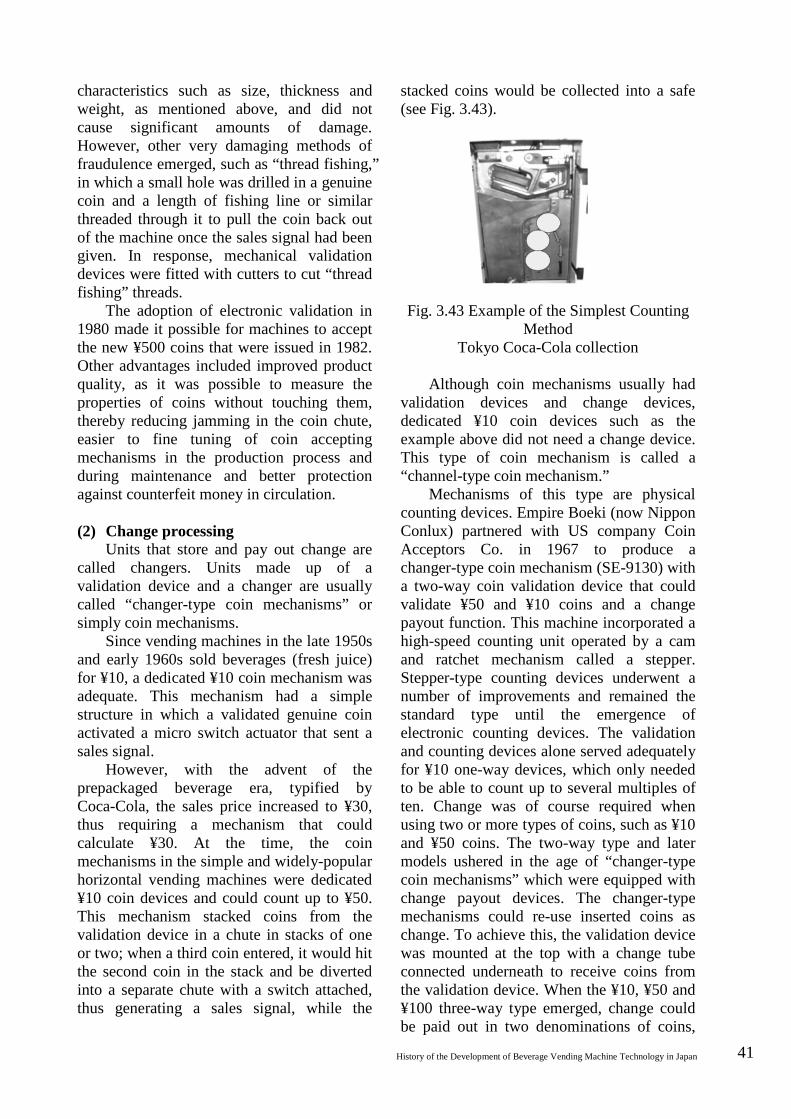
History of the Development of Beverage Vending Machine Technology in Japan 41
characteristics such as size, thickness and weight, as mentioned above, and did not cause significant amounts of damage. However, other very damaging methods of fraudulence emerged, such as “thread fishing,” in which a small hole was drilled in a genuine coin and a length of fishing line or similar threaded through it to pull the coin back out of the machine once the sales signal had been given. In response, mechanical validation devices were fitted with cutters to cut “thread fishing” threads.
The adoption of electronic validation in 1980 made it possible for machines to accept the new ¥500 coins that were issued in 1982. Other advantages included improved product quality, as it was possible to measure the properties of coins without touching them, thereby reducing jamming in the coin chute, easier to fine tuning of coin accepting mechanisms in the production process and during maintenance and better protection against counterfeit money in circulation. (2) Change processing
Units that store and pay out change are called changers. Units made up of a validation device and a changer are usually called “changer-type coin mechanisms” or simply coin mechanisms.
Since vending machines in the late 1950s and early 1960s sold beverages (fresh juice) for ¥10, a dedicated ¥10 coin mechanism was adequate. This mechanism had a simple structure in which a validated genuine coin activated a micro switch actuator that sent a sales signal.
However, with the advent of the prepackaged beverage era, typified by Coca-Cola, the sales price increased to ¥30, thus requiring a mechanism that could calculate ¥30. At the time, the coin mechanisms in the simple and widely-popular horizontal vending machines were dedicated ¥10 coin devices and could count up to ¥50. This mechanism stacked coins from the validation device in a chute in stacks of one or two; when a third coin entered, it would hit the second coin in the stack and be diverted into a separate chute with a switch attached, thus generating a sales signal, while the
stacked coins would be collected into a safe (see Fig. 3.43).
Fig. 3.43 Example of the Simplest Counting Method
Tokyo Coca-Cola collection
Although coin mechanisms usually had validation devices and change devices, dedicated ¥10 coin devices such as the example above did not need a change device. This type of coin mechanism is called a “channel-type coin mechanism.”
Mechanisms of this type are physical counting devices. Empire Boeki (now Nippon Conlux) partnered with US company Coin Acceptors Co. in 1967 to produce a changer-type coin mechanism (SE-9130) with a two-way coin validation device that could validate ¥50 and ¥10 coins and a change payout function. This machine incorporated a high-speed counting unit operated by a cam and ratchet mechanism called a stepper. Stepper-type counting devices underwent a number of improvements and remained the standard type until the emergence of electronic counting devices. The validation and counting devices alone served adequately for ¥10 one-way devices, which only needed to be able to count up to several multiples of ten. Change was of course required when using two or more types of coins, such as ¥10 and ¥50 coins. The two-way type and later models ushered in the age of “changer-type coin mechanisms” which were equipped with change payout devices. The changer-type mechanisms could re-use inserted coins as change. To achieve this, the validation device was mounted at the top with a change tube connected underneath to receive coins from the validation device. When the ¥10, ¥50 and ¥100 three-way type emerged, change could be paid out in two denominations of coins,
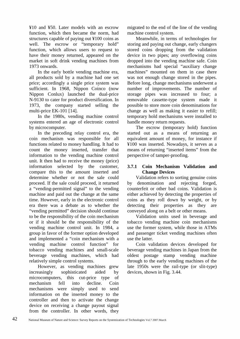
42 National Museum of Nature and Science: Survey Reports on the Systemization of Technologies Vol.7 2007.March
¥10 and ¥50. Later models with an escrow function, which then became the norm, had structures capable of paying out ¥100 coins as well. The escrow or “temporary hold” function, which allows users to request to have their money returned, appeared on the market in soft drink vending machines from 1973 onwards.
In the early bottle vending machine era, all products sold by a machine had one set price; accordingly a single price system was sufficient. In 1968, Nippon Coinco (now Nippon Conlux) launched the dual-price N-9130 to cater for product diversification. In 1973, the company started selling the multi-price EK-101 [14].
In the 1980s, vending machine control systems entered an age of electronic control by microcomputer.
In the preceding relay control era, the coin mechanism was responsible for all functions related to money handling. It had to count the money inserted, transfer that information to the vending machine control unit. It then had to receive the money (price) information selected by the customer, compare this to the amount inserted and determine whether or not the sale could proceed. If the sale could proceed, it returned a “vending-permitted signal” to the vending machine and paid out the change at the same time. However, early in the electronic control era there was a debate as to whether the “vending permitted” decision should continue to be the responsibility of the coin mechanism or if it should be the responsibility of the vending machine control unit. In 1984, a group in favor of the former option developed and implemented a “coin mechanism with a vending machine control function” for tobacco vending machines and small-scale beverage vending machines, which had relatively simple control systems.
However, as vending machines grew increasingly sophisticated aided by microcomputers, this cut-price type of mechanism fell into decline. Coin mechanisms were simply used to send information on the inserted money to the controller and then to activate the change device on receiving a change payout signal from the controller. In other words, they
migrated to the end of the line of the vending machine control system.
Meanwhile, in terms of technologies for storing and paying out change, early changers stored coins dropping from the validation device in two pipes; any overflowing coins dropped into the vending machine safe. Coin mechanisms had special “auxiliary change machines” mounted on them in case there was not enough change stored in the pipes. Before long, change mechanisms underwent a number of improvements. The number of storage pipes was increased to four; a removable cassette-type system made it possible to store more coin denominations for change as well as making it easier to refill; temporary hold mechanisms were installed to handle money return requests.
The escrow (temporary hold) function started out as a means of returning an equivalent amount of money, for instance if ¥100 was inserted. Nowadays, it serves as a means of returning “inserted items” from the perspective of tamper-proofing. 3.7.1 Coin Mechanism Validation and
Change Devices Validation refers to sorting genuine coins
by denomination and rejecting forged, counterfeit or other bad coins. Validation is either achieved by detecting the properties of coins as they roll down by weight, or by detecting their properties as they are conveyed along on a belt or other means.
Validation units used in beverage and tobacco vending machine coin mechanisms use the former system, while those in ATMs and passenger ticket vending machines often use the latter.
Coin validation devices developed for beverage vending machines in Japan from the oldest postage stamp vending machine through to the early vending machines of the late 1950s were the rail-type (or slit-type) devices, shown in Fig. 3.44.
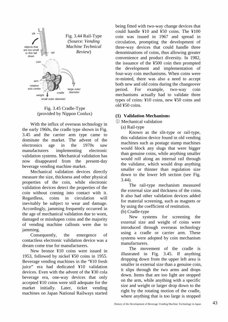
History of the Development of Beverage Vending Machine Technology in Japan 43
Fig. 3.45 Cradle-Type (provided by Nippon Conlux)
With the influx of overseas technology in
the early 1960s, the cradle type shown in Fig. 3.45 and the carrier arm type came to dominate the market. The advent of the electronics age in the 1970s saw manufacturers implementing electronic validation systems. Mechanical validation has now disappeared from the present-day beverage vending machine market.
Mechanical validation devices directly measure the size, thickness and other physical properties of the coin, while electronic validation devices detect the properties of the coin without coming into contact with it. Regardless, coins in circulation will inevitably be subject to wear and damage. Accordingly, jamming frequently occurred in the age of mechanical validation due to worn, damaged or misshapen coins and the majority of vending machine callouts were due to jamming.
Consequently, the emergence of contactless electronic validation device was a dream come true for manufacturers.
New bronze ¥10 coins were issued in 1953, followed by nickel ¥50 coins in 1955. Beverage vending machines in the “¥10 fresh juice” era had dedicated ¥10 validation devices. Even with the advent of the ¥30 cola beverage era, one-way devices that only accepted ¥10 coins were still adequate for the market initially. Later, ticket vending machines on Japan National Railways started
being fitted with two-way change devices that could handle ¥10 and ¥50 coins. The ¥100 coin was issued in 1967 and spread in circulation, prompting the development of three-way devices that could handle three denominations of coins, thus allowing greater convenience and product diversity. In 1982, the issuance of the ¥500 coin then prompted the development and implementation of four-way coin mechanisms. When coins were re-minted, there was also a need to accept both new and old coins during the changeover period. For example, two-way coin mechanisms actually had to validate three types of coins: ¥10 coins, new ¥50 coins and old ¥50 coins. (1) Validation Mechanisms ○1 Mechanical validation
(a) Rail-type Known as the slit-type or rail-type,
this validation device found in old vending machines such as postage stamp machines would block any slugs that were bigger than genuine coins, while anything smaller would roll along an internal rail through the validator, which would drop anything smaller or thinner than regulation size down to the lower left section (see Fig. 3.44).
The rail-type mechanism measured the external size and thickness of the coins. It also had other validation devices added for material screening, such as magnets or by using the coefficient of restitution. (b) Cradle-type
New systems for screening the external size and weight of coins were introduced through overseas technology using a cradle or carrier arm. These systems were adopted by coin mechanism manufacturers.
The movement of the cradle is illustrated in Fig. 3.45. If anything dropping down from the upper left area is smaller in external size than a genuine coin, it slips through the two arms and drops down. Items that are too light are stopped on the arm, while anything with a specific size and weight or larger drop down to the right by the rotating motion of the cradle, where anything that is too large is stopped
slit
objects that are too small
or thin fall down
coin
arm
rotation axis center
weight cradle
large outer diameter
small outer diameter
rail
Fig. 3.44 Rail-Type (Source: Vending
Machine Technical Review)
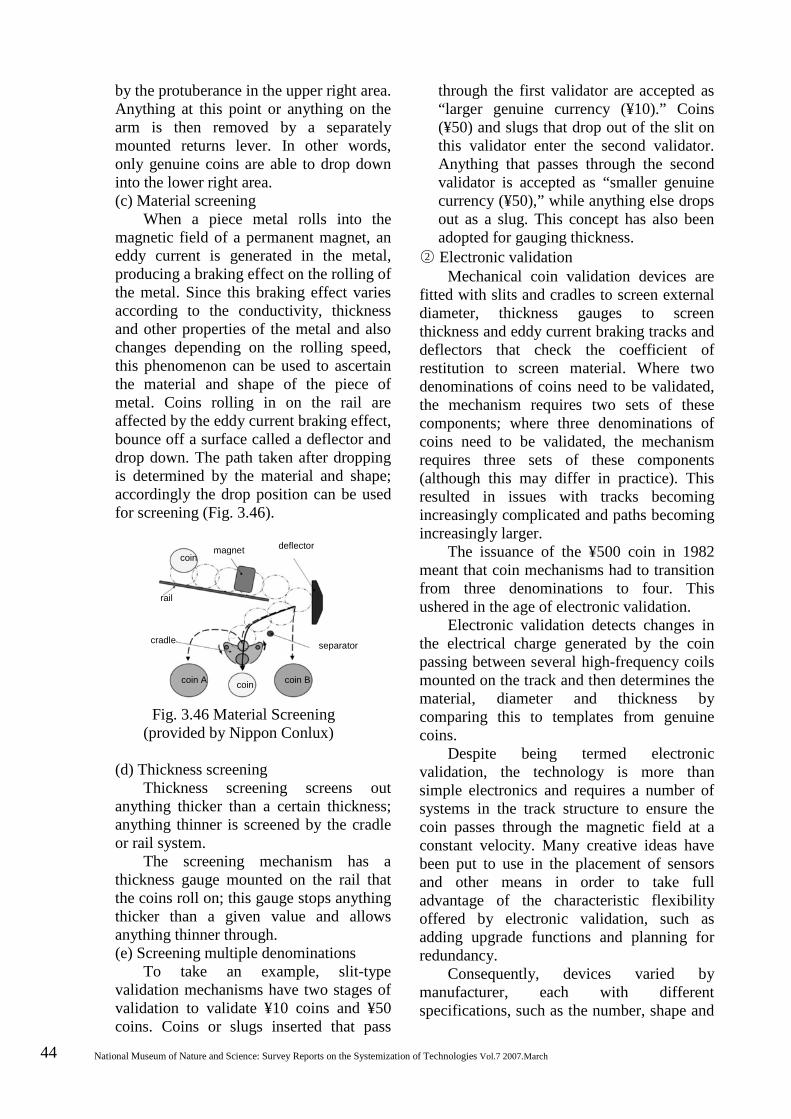
44 National Museum of Nature and Science: Survey Reports on the Systemization of Technologies Vol.7 2007.March
by the protuberance in the upper right area. Anything at this point or anything on the arm is then removed by a separately mounted returns lever. In other words, only genuine coins are able to drop down into the lower right area. (c) Material screening
When a piece metal rolls into the magnetic field of a permanent magnet, an eddy current is generated in the metal, producing a braking effect on the rolling of the metal. Since this braking effect varies according to the conductivity, thickness and other properties of the metal and also changes depending on the rolling speed, this phenomenon can be used to ascertain the material and shape of the piece of metal. Coins rolling in on the rail are affected by the eddy current braking effect, bounce off a surface called a deflector and drop down. The path taken after dropping is determined by the material and shape; accordingly the drop position can be used for screening (Fig. 3.46).
Fig. 3.46 Material Screening (provided by Nippon Conlux)
(d) Thickness screening Thickness screening screens out
anything thicker than a certain thickness; anything thinner is screened by the cradle or rail system.
The screening mechanism has a thickness gauge mounted on the rail that the coins roll on; this gauge stops anything thicker than a given value and allows anything thinner through. (e) Screening multiple denominations
To take an example, slit-type validation mechanisms have two stages of validation to validate ¥10 coins and ¥50 coins. Coins or slugs inserted that pass
through the first validator are accepted as “larger genuine currency (¥10).” Coins (¥50) and slugs that drop out of the slit on this validator enter the second validator. Anything that passes through the second validator is accepted as “smaller genuine currency (¥50),” while anything else drops out as a slug. This concept has also been adopted for gauging thickness.
○2 Electronic validation Mechanical coin validation devices are
fitted with slits and cradles to screen external diameter, thickness gauges to screen thickness and eddy current braking tracks and deflectors that check the coefficient of restitution to screen material. Where two denominations of coins need to be validated, the mechanism requires two sets of these components; where three denominations of coins need to be validated, the mechanism requires three sets of these components (although this may differ in practice). This resulted in issues with tracks becoming increasingly complicated and paths becoming increasingly larger.
The issuance of the ¥500 coin in 1982 meant that coin mechanisms had to transition from three denominations to four. This ushered in the age of electronic validation.
Electronic validation detects changes in the electrical charge generated by the coin passing between several high-frequency coils mounted on the track and then determines the material, diameter and thickness by comparing this to templates from genuine coins.
Despite being termed electronic validation, the technology is more than simple electronics and requires a number of systems in the track structure to ensure the coin passes through the magnetic field at a constant velocity. Many creative ideas have been put to use in the placement of sensors and other means in order to take full advantage of the characteristic flexibility offered by electronic validation, such as adding upgrade functions and planning for redundancy.
Consequently, devices varied by manufacturer, each with different specifications, such as the number, shape and
coin magnet deflector
rail
cradle separator
coin A coin coin B

History of the Development of Beverage Vending Machine Technology in Japan 45
amplitude change
amplitude change
・sensor placement ・sensor
amplifier
excitation coil coin receiving coil
oscillation circuit
parameter extraction
Compar- ison
Determi- nation
reference values
layout of the sensors (high-frequency coils) and the oscillating frequency. As the transition to electronic systems progressed, tampering methods also diversified. A typical method of tampering in the late 1980s involved pouring laundry detergent or other surfactant into the coin slot, thereby damaging the electronic components and disrupting the control process, making it possible to defraud the amount of change given. Since even children could do this, it spread throughout the whole country and a great amount of effort was spent in countermeasures against losing change as well as countermeasures against damage to validators.
Figure 3.47 shows a typical electronic validation mechanism. Several coils of various shapes are usually mounted along the track. Following a simple mechanical screening of shape and thickness, the coin passes near the coils at a constant velocity while the device reads the variations in frequency and phase, compares these to reference values (values from a genuine coin processed to provide the statistics), makes a determination and opens or closes the gate.
The principle of electronic validation can be explained by referring to a description in Vending Machine Technical Review. The excitation coil and receiving coil shown in Fig. 3.48 are placed on either side of the coin track so as to be electromagnetically coupled. The excitation coil is connected to the oscillation circuit, while the receiving coil is connected to the parameter detector, comparison unit, reference values unit and the determination unit. The excitation coil generates a certain high-frequency magnetic field by means of the oscillation circuit and an induced current is generated in the receiving coil by electromagnetic induction.
Fig. 3.47 Electronic Validation
Fig. 3.48 Electronic Validation Principle
When a coin comes between the two coils at this point, an eddy current is generated within the coin. The magnetic field of the eddy current acts in a direction contrary to the magnetic field generated when the coin is not present, thereby altering the impedance and inductance of the coils. The electromotive force induced in the receiving coil changes with the changes in the magnetic flux according to the specific properties of the coin. The most suitable frequencies are used for screening the coin material and form (diameter and thickness) in order to observe these changes in electromotive force. Changes in voltage, frequency and phase are used as parameters for identifying these changes. The data extracted using these parameters are then compared with predetermined reference values (taken by measuring and processing the statistics from a genuine coin) in the comparison unit and a determination is made as to whether the coin is genuine or counterfeit.
Developments in this technology were largely pioneered by overseas manufacturers. Later manufacturers spent substantial time in development to avoid patent disputes over the basic technology. Overseas manufacturers, such as those in Europe, had to ensure their machines could accurately validate an
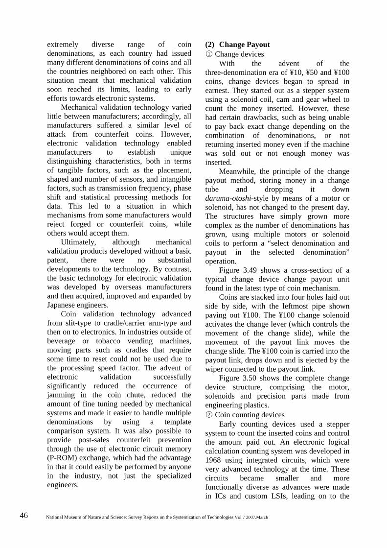
46 National Museum of Nature and Science: Survey Reports on the Systemization of Technologies Vol.7 2007.March
extremely diverse range of coin denominations, as each country had issued many different denominations of coins and all the countries neighbored on each other. This situation meant that mechanical validation soon reached its limits, leading to early efforts towards electronic systems.
Mechanical validation technology varied little between manufacturers; accordingly, all manufacturers suffered a similar level of attack from counterfeit coins. However, electronic validation technology enabled manufacturers to establish unique distinguishing characteristics, both in terms of tangible factors, such as the placement, shaped and number of sensors, and intangible factors, such as transmission frequency, phase shift and statistical processing methods for data. This led to a situation in which mechanisms from some manufacturers would reject forged or counterfeit coins, while others would accept them.
Ultimately, although mechanical validation products developed without a basic patent, there were no substantial developments to the technology. By contrast, the basic technology for electronic validation was developed by overseas manufacturers and then acquired, improved and expanded by Japanese engineers.
Coin validation technology advanced from slit-type to cradle/carrier arm-type and then on to electronics. In industries outside of beverage or tobacco vending machines, moving parts such as cradles that require some time to reset could not be used due to the processing speed factor. The advent of electronic validation successfully significantly reduced the occurrence of jamming in the coin chute, reduced the amount of fine tuning needed by mechanical systems and made it easier to handle multiple denominations by using a template comparison system. It was also possible to provide post-sales counterfeit prevention through the use of electronic circuit memory (P-ROM) exchange, which had the advantage in that it could easily be performed by anyone in the industry, not just the specialized engineers.
(2) Change Payout ○1 Change devices
With the advent of the three-denomination era of ¥10, ¥50 and ¥100 coins, change devices began to spread in earnest. They started out as a stepper system using a solenoid coil, cam and gear wheel to count the money inserted. However, these had certain drawbacks, such as being unable to pay back exact change depending on the combination of denominations, or not returning inserted money even if the machine was sold out or not enough money was inserted.
Meanwhile, the principle of the change payout method, storing money in a change tube and dropping it down daruma-otoshi-style by means of a motor or solenoid, has not changed to the present day. The structures have simply grown more complex as the number of denominations has grown, using multiple motors or solenoid coils to perform a “select denomination and payout in the selected denomination” operation.
Figure 3.49 shows a cross-section of a typical change device change payout unit found in the latest type of coin mechanism.
Coins are stacked into four holes laid out side by side, with the leftmost pipe shown paying out ¥100. The ¥100 change solenoid activates the change lever (which controls the movement of the change slide), while the movement of the payout link moves the change slide. The ¥100 coin is carried into the payout link, drops down and is ejected by the wiper connected to the payout link.
Figure 3.50 shows the complete change device structure, comprising the motor, solenoids and precision parts made from engineering plastics. ○2 Coin counting devices
Early counting devices used a stepper system to count the inserted coins and control the amount paid out. An electronic logical calculation counting system was developed in 1968 using integrated circuits, which were very advanced technology at the time. These circuits became smaller and more functionally diverse as advances were made in ICs and custom LSIs, leading on to the
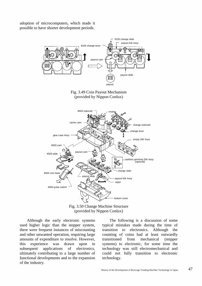
History of the Development of Beverage Vending Machine Technology in Japan 47
adoption of microcomputers, which made it possible to have shorter development periods.
Fig. 3.49 Coin Payout Mechanism (provided by Nippon Conlux)
Fig. 3.50 Change Machine Structure
(provided by Nippon Conlux)
Although the early electronic systems used higher logic than the stepper system, there were frequent instances of miscounting and other unwanted operation, requiring large amounts of expenditure to resolve. However, this experience was drawn upon in subsequent applications of electronics, ultimately contributing to a large number of functional developments and to the expansion of the industry.
The following is a discussion of some typical mistakes made during the time of transition to electronics. Although the counting of coins had at least outwardly transitioned from mechanical (stepper systems) to electronic, for some time the technology was still electromechanical and could not fully transition to electronic technology.
¥100 change slide payout link Assy
¥100 change lever
payout cam
payout slide
payout
¥500 solenoid motor
carrier cam
gear case Assy
¥500 cam
¥500 slide payout cam
¥500 coin base
¥500 pulse switch
payout slide
bottom cover
wiper payout link Assy
change slide
cashbox jamming SW Assy (optional)
empty SW Assy
change lever
change solenoid
48 National Museum of Nature and Science: Survey Reports on the Systemization of Technologies Vol.7 2007.March
The switch-type electrical contacts used in steppers handled current in amperes and were developed for wear resistance and melt resistance, with the working speed dependent on mechanical movement. By contrast, electronic systems operated on energy measured in microamperes and had a faster working speed by far.
Counting in the mechanical validation era was performed as coins entered the validation device and activated a micro switch actuator positioned on the rolling track. The opening and closing of the switch sent current to the relays, motor, solenoids and other components, thereby activating the stepper. With the advent of the early electronics age of transistors and ICs, the stepper system was replaced by transistor logic circuits. However, since the input still came from the micro switch contacts as it had for the stepper system, the miscounting continued. Whereas the relays, motor, solenoids and other electromagnetic devices had not really been affected by contact chattering (bouncing) [Footnote 5] from the micro switch and other components, the electronic circuits could not count a single ON-OFF of the contacts, as they received all chattering (bouncing) oscillation [Footnote 5] as a signal and kept counting. This was finally resolved by the development of a proximity switch, which made the input contactless.
With the industry revolving around electromechanical technology, manufacturers and users combined their concentrated efforts to master electromagnetic technology. Initiatives to transition to electronics undertaking ahead of other industries such as home appliances resulted in high vending machine functionality.
Functions made possible by electronics included multiple price setting (multi-price) to accommodate diversification of tobacco or beverage products, an escrow (temporary hold) function to allow users to request their money to be returned, a payout verification [Footnote 5] Contact chattering refers to repeated electrical switching on and off due to bouncing or rolling when the contacts touch. Since this can become a signal in a circuit with a high operating speed, various countermeasures have been devised.
function to monitor missed payments by the change payout mechanism, a sum display function to show the amount inserted on a monitor, a fault diagnosis function and recording of sales summaries and withdrawals/deposits by denomination, as well as the previously mentioned “unit with a built-in control function,” making it easy to develop low-cost vending machines with simple functions.
While vending machine function development started out being adjusted to suit various stakeholder “needs,” for coin mechanisms it was possible to incorporate new technologies based on relatively volitional ideas. Accordingly, active efforts to develop electronic coin mechanisms played a major role in the transition to electronic vending machines, while efforts to standardize the industry also enabled compatibility between manufacturers.
Such active initiatives took vending machines from being “machines that take money and dispense products” to being an active part of a social network geared towards an information-driven society. Specifically, this started in the standalone era with the digitization of coin and bill systems and the acceptance of prepaid cards; vending machines have continued to be closely linked to networked society in various ways, such as incorporating various payment methods by acting as terminals for ID card network systems, adding information media functions to vending machines and having security systems linked with mobile phones. 3.7.2 Bill Validators
Banknote validation differs in structure and performance depending on the machine in which the device is mounted, just as it is with coins. Bill validation devices for beverage, food or tobacco vending machines are made up of a bill validation section and an inserted bill storage section, integrated into one unit like the changers for coins.
While coins roll on a track by weight, are screened as genuine or counterfeit by denomination and drop down either into the safe or as change, bills are transported from the intake slot on a moving belt and validated by a sensor while moving. Genuine bills are
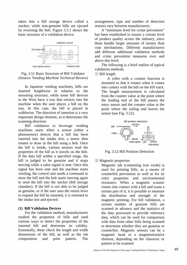
History of the Development of Beverage Vending Machine Technology in Japan 49
taken into a bill storage device called a stacker, while non-genuine bills are ejected by reversing the belt. Figure 3.5.1 shows the basic structure of a validation device.
Fig. 3.51 Basic Structure of Bill Validator (Source: Vending Machine Technical Review)
In Japanese vending machines, bills are inserted lengthwise in relation to the mounting structure, while some bill devices in the West have a tray that retracts into the machine when the user places a bill on the tray. In this case, the bill is placed in widthwise. The direction of insertion is a very important design element, as it determines the scanning direction.
Bill validation in beverage vending machines starts when a sensor (often a photosensor) detects that a bill has been inserted into the intake slot; a motor then rotates to draw in the bill using a belt. Once the bill is inside, various sensors read the properties of the bill as it travels on the belt. If the data fall within a specified range, the bill is judged to be genuine and it stops moving while a sales signal is sent. Once this signal has been sent and the machine starts vending, the control unit sends a command to store the bill and the belt starts moving again to send the bill into the stacker (bill storage chamber). If the bill is not able to be judged as genuine, or if the user uses the return lever to request the bill be returned, it is returned to the intake slot and ejected. (1) Bill Validation Devices
For the validation method, manufacturers studied the properties of bills and used various ways to detect the properties of the inserted bill and determine its validity. Essentially, these check the length and width dimensions of the bill, as well as the ink composition and print pattern. The
arrangement, type and number of detection sensors vary between manufacturers.
A “minimum level for crime prevention” has been established to ensure a certain level of product quality across the industry, since these handle larger amounts of money than coin mechanisms. Different manufacturers add different additional validation methods and crime prevention measures over and above this level.
The following is a brief outline of typical validation methods. ○1 Bill length
A roller with a counter function is mounted so that it rotates when it comes into contact with the bill on the bill track. The length measurement is calculated from the counter value at the point where the leading end of the bill passes the entry sensor and the counter value at the point where the tailing end leaves the sensor (see Fig. 3.52).
Fig. 3.52 Bill Position Detection ○2 Magnetic properties
Magnetic ink (containing iron oxide) is used for printing bills, as a means of counterfeit prevention as well as for its color properties and environmental resistance. When a magnetic scanner comes into contact with a bill and scans a certain part of it, it is possible to measure the distribution and strength of the magnetic printing. For bill validation, a certain number of genuine bills are scanned in advance and the statistics of the data processed to provide reference data, which can be used for comparison with data from other bills being scanned to determine whether they are genuine or counterfeit. Magnetic sensors can be a magnetic head or a magnetoresistive element, depending on the character or pattern to be scanned.
validation sensor
bill intake slot
start signal sensor transport belt
bill position detection sensor
bill
roller
photo interrupter photo
transistor

50 National Museum of Nature and Science: Survey Reports on the Systemization of Technologies Vol.7 2007.March
○3 Optical properties While it was initially used for
printed pattern detection, advances in optical devices (such as photocopiers) made it difficult to determine if a bill was genuine or counterfeit by pattern detection alone. Now, even ink composition and color phase are checked. Checking optical properties involves statistically processing reflected light data and penetrated light intensity data to create reference values for comparison.
Since bills are worth more than coins and crime prevention measures are even more important, the Japan Vending Machine Manufacturers Association established the Independent Handling Guidelines for Banknote Identification Devices in 1982. According to these guidelines, careful handling is required: “in terms of machine performance, it must be capable of detecting the electromagnetic properties of banknotes with precision and complexity; banknote checkpoints must incorporate elements of external form (dimensions) and particulars (magnetic, optical, etc.). When an identification device senses an abnormality, it must be structured to stop receiving the banknote and to return it. As a black box, it must also show consideration for safety, so that maintenance and adjustment cannot be performed by anyone other than a manufacturer or related party.”
According to the National Police Agency, there were 807 instances of counterfeit bills detected in 1982; by 2004, this figure had risen to almost 30,000. Given this situation, the Bank of Japan re-issued three denominations of bills, ¥1,000, ¥5,000 and ¥10,000 at the end of 2004, using the latest counterfeit prevention technology. The ¥1,000 bill, which was accepted by beverage vending machines, had a number of features added to be used for identification, including a “latent pearl image pattern,” “watermark bar pattern,” “latent image pattern,” “intaglio printing” and “identification marks.” Common instances of bill validation device related
crime were “cutting and pasting genuine bills” and “bill poaching.” These were partly due to enthusiasts creating their own techniques to try to outsmart the technology of the manufacturers.
In the former case, the counterfeiters would work out the location of the sensor and then use part of a genuine bill for that section only, using ordinary paper for the rest. Since different manufacturers placed sensors in different locations, one bill could be cut into several pieces to work in different models. In the latter case, the counterfeiters would cut a bill in two lengthwise, join it together in such a way that the tape would easily break, attach strong tape to each half so as to get the two pieces back again, and then insert it into the vending machine. Since the bill was genuine, it would be accepted and a sales signal would be given. At that point, the counterfeiters would forcibly pull the note back out using the pull tape and then afterwards use the return lever to steal the change.
While early intake slots had a central pillar to prevent bills from being pulled out again, counterfeiters discovered this and accordingly split the bill in two to retract it. When engineers added another pillar as an additional countermeasures, counterfeiters responded by splitting bills into three. The damage from this “pulling out” method became known from instances when it went wrong and pieces were left behind in the machine. The reality was that this was a battle of wits between vending machine manufacturers and criminal minds.
(2) Bill Storage Devices (Stackers)
Bill storage units are known as stackers. Figure 3.53 shows a typical design with a bill validation device and a stacker underneath it. This example shows a two-denomination bill validator that can validate ¥1,000 bills and ¥10,000 bills or ¥5,000 bills. Consequently, the stacker is structured to accommodate two bill denominations.
Most beverage vending machine ¥1,000 bill validators have a stacker structure that

History of the Development of Beverage Vending Machine Technology in Japan 51
can store around 100 bills. In recent years there has been an increase in crimes involving the use of tools to damage vending machines and steal bills from the bill validator. As a countermeasure against vending machine crimes, operators have been called to empty the coins and bills from the safe and stacker on a daily basis. As this practice has become more widespread, there has been less need for 100-bill storage capacity, other than a few exceptions.
Fig. 3.53 Stacker
(Source: Vending Machine Technical Review)
While dedicated ¥1,000 bill capability is adequate for beverage vending machines as they sell low-priced products, other vending machines sell products for prices over ¥1,000, such as flowers or videotapes. These machines must be capable of accepting ¥5,000 and ¥10,000 bills and paying out ¥1,000 bills in change. Such a device was developed in 1997. This bill validator, known as a recycling-type bill validation device, uses the inserted ¥1,000 bills for change. 3.7.3 Control Technology
The oldest vending machine still in existence (a sake vending machine in Ninohe) had a clockwork control system. The clockwork mechanism opened a faucet to pour sake into a vessel provided.
Once beverage vending machines became industrialized in the late 1950s, the motors were powered by electricity and the control system was also electric. The ¥10 juice vending machines had cups in a tube that the user would place into the vending outlet by hand; when the user then inserted a ¥10 coin, the coin would activate an actuator switch that drove the vending device to
dispense a cup of juice and complete the vending cycle.
Although this was adequate for the time, as beverage vending machines and other machines entered an era of being able to select and buy from two or more products, it became necessary to have a control system with electromagnetic relay interlocking circuits (see Fig. 5.34).
Fig. 3.54 Electric Interlock Circuit
Even so, there were rumors that early domestically-produced vending machines “could sell two items for ¥30 by pushing two buttons at a particular timing” and there were frequent instances of tampering. While it could not be inferred from the circuit diagram, the rumor was ultimately deemed to be true, as the solenoid vending device would short circuit due to arcing between relay contacts.
Eventually it was no longer possible for sequence control by switches and magnetic relays to meet the functional demands, such as vending products with different prices (multi-price) and reading sales information, and the transition was made to electronics.
Sanyo Electric developed the first microcomputer-controlled meal ticket vending machine in 1978, ushering in an age of microcomputer control for vending machines in all industries.
Microcomputer control in beverage vending machines started out as a 4-bit system and soon progressed to an 8-bit system before transitioning to a 16-bit system soon after that. The initial control system was a centralized control system, in which a single microcomputer controlled all functions of the vending machine, as in the example shown in Fig. 3.55. This development led to expansion in vending machine size, diversification of products, multiple price design and a number of functions useful to operation, such as recording sales information
¥1,000 bill storage (bills for
change) bill intake slot
¥10,000/ ¥5,000 bill
storage unit
return slot
vending device A
vending device B
vending device C
vending device D
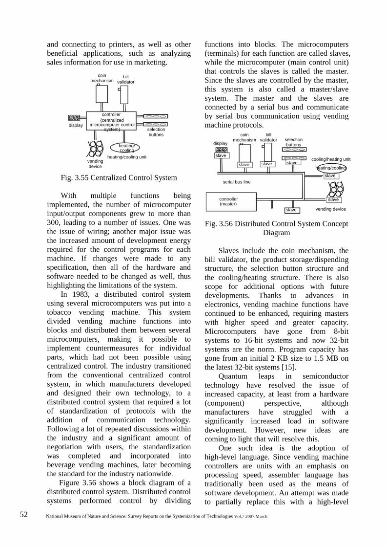
52 National Museum of Nature and Science: Survey Reports on the Systemization of Technologies Vol.7 2007.March
coin mechanism
bill validator
display
controller
selection buttons
vending device
heating/ cooling
heating/cooling unit
(centralized microcomputer control
system)
and connecting to printers, as well as other beneficial applications, such as analyzing sales information for use in marketing.
Fig. 3.55 Centralized Control System
With multiple functions being implemented, the number of microcomputer input/output components grew to more than 300, leading to a number of issues. One was the issue of wiring; another major issue was the increased amount of development energy required for the control programs for each machine. If changes were made to any specification, then all of the hardware and software needed to be changed as well, thus highlighting the limitations of the system.
In 1983, a distributed control system using several microcomputers was put into a tobacco vending machine. This system divided vending machine functions into blocks and distributed them between several microcomputers, making it possible to implement countermeasures for individual parts, which had not been possible using centralized control. The industry transitioned from the conventional centralized control system, in which manufacturers developed and designed their own technology, to a distributed control system that required a lot of standardization of protocols with the addition of communication technology. Following a lot of repeated discussions within the industry and a significant amount of negotiation with users, the standardization was completed and incorporated into beverage vending machines, later becoming the standard for the industry nationwide.
Figure 3.56 shows a block diagram of a distributed control system. Distributed control systems performed control by dividing
functions into blocks. The microcomputers (terminals) for each function are called slaves, while the microcomputer (main control unit) that controls the slaves is called the master. Since the slaves are controlled by the master, this system is also called a master/slave system. The master and the slaves are connected by a serial bus and communicate by serial bus communication using vending machine protocols.
Fig. 3.56 Distributed Control System Concept
Diagram
Slaves include the coin mechanism, the bill validator, the product storage/dispending structure, the selection button structure and the cooling/heating structure. There is also scope for additional options with future developments. Thanks to advances in electronics, vending machine functions have continued to be enhanced, requiring masters with higher speed and greater capacity. Microcomputers have gone from 8-bit systems to 16-bit systems and now 32-bit systems are the norm. Program capacity has gone from an initial 2 KB size to 1.5 MB on the latest 32-bit systems [15].
Quantum leaps in semiconductor technology have resolved the issue of increased capacity, at least from a hardware (component) perspective, although manufacturers have struggled with a significantly increased load in software development. However, new ideas are coming to light that will resolve this.
One such idea is the adoption of high-level language. Since vending machine controllers are units with an emphasis on processing speed, assembler language has traditionally been used as the means of software development. An attempt was made to partially replace this with a high-level
display
coin mechanism
bill validator selection
buttons
slave
slave slave slave cooling/heating unit
heating/cooling slave
serial bus line
controller
slave
slave
vending device (master)

History of the Development of Beverage Vending Machine Technology in Japan 53
language (such as C); most of the development has now gradually shifted to high-level language.
Fig. 3.57 Addition of Sub-Controller and High-Speed Bus
Another idea has been the addition of
sub-controllers. Conventional distributed control systems were polling/selecting systems in which the master called and communicated with the slave, with relatively slow-speed bus specifications. Consequently, it was difficult to use slaves for component controllers needing higher-speed responses, such as remote controls for function design or selection buttons used by customers to specify their desired product.
To resolve these issues, the addition of a new, high-speed bus line separate from the existing bus line has been proposed and is being implemented. The high-speed serial bus used is a CSMA/CD (carrier-sense multiple access with collision detection) and is capable of achieving high-speed operation not possible with the master/slave system, as well as allowing the easy addition of control blocks for upgrading functions. This also has a number of advantages from a hardware perspective, such as drastically reducing the amount of electrical wires. In the past, multiple product selection buttons, for example, had individual wiring for each button, requiring many bundles of wires. Building in an IC chip for each product button and having that chip connect to the high-speed serial bus has resulted in a dramatic reduction in electrical wires [16].
Not only has the use of sub-controllers made vending machine hardware development more efficient, the use of the
Java [Footnote 6] platform has even made it possible for vending machine users to develop their own functions.
In recent years, with vending machines becoming very widespread, location points becoming saturated and little prospect of any major increase in sales, beverage manufacturers and other users have begun to take a keen interest in the efficient management of vending machines.
In the past, manufacturers and users worked together to set the standards for vending machine sales information gathering systems and contributed to improved POS and route sales efficiency. Now these systems have become widespread to a certain extent, the needs of individual vending machine users are becoming more specific due to differences in operating environment, plans and policies; universal specifications are no longer adequate.
To meet these needs, it was decided to develop the execution environment of the sub-controller using the Java programming language, with the aim of speedily developing client-specific application software.
As the internet became more widespread, machines have started becoming terminals for a diversely networked society. Vending machines can be expected to play a significant role in this as software development for this opens up.
In 1999, the European Vending Association (EVA) [Footnote 7] that oversees the members of the vending machine industry throughout Europe proposed to the Japan Vending Machine Manufacturers Association (JMVA) that the EVA standard MDB/ICP (multi-drop bus/internal communication protocol) system become the international standard.
MDB/ICP is a vending machine control system specification that has a serial bus and operates by master/slave microcomputers. In [Footnote 6] Java, a registered trademark of American company Sun Microsystems, Inc., is a programming language developed to reduce the complexity of developing and maintaining software. The Java platform refers to the program’s execution and development environments. [Footnote 7] The EVA is an organization established in 1995 and made up of vending machines manufacturers, operators, bottlers and cash-handling machine manufacturers, mainly from the EU, involved in lobbying and technical standardization activities, primarily for EU institutions.
coin mechanism
bill validator card
devices, etc.
slave slave slave
Serial bus
controller
sub-controller (applied functions)
sales heating/ cooling
controller
selection buttons display
message display
high-speed serial bus
(basic functions)

54 National Museum of Nature and Science: Survey Reports on the Systemization of Technologies Vol.7 2007.March
1998, the EVA established “MDB/ICP Ver.1” for communications specifications and procedures, while the basic specifications, including the patent, for its predecessor MDB were acquired from Japanese manufacturers by the American Coca-Cola Company and developed. Later, MDB spread throughout the United States and became the standard for the National Automatic Merchandising Association (NAMA) in the 1990s.
On the issue of global standardization, the JMVA worked with the EVA in 1991 to develop a “system that can fully be utilized for the next generation.” This was proposed to become the global standard, but no further progress was made.
Electronics technology has continued to develop with no sign of stopping. Just as the early MDB of the NAMA is “similar yet different” to the integrated MDB/ICP that was later established, there is a significant difference in specifications between MDB/ICP and the Japanese systems that were developed even earlier. The fact that no progress has been made on the Japanese proposal suggests that it is difficult to establish a global standard in an area of remarkable progress in development.
For example, the JMVA standardized the distributed control system in 1991. The system had designated hardware and software standards to handle diversification (expansion using slaves), for economic potential (development costs, material costs) and for ease of maintenance. In 2002, Fuji Electric implemented a system with a high-speed serial bus added, as discussed above. In other words, within around ten years, there had to be a new standard for this basic component.
On top of that, with so many different social and technological environments around the world, it is impossible to have universal consideration all the time.
In light of this, the JMVA is proposing the joint development of a next-generation system.
If this course of events highlights the difficulty of standardization, the challenge is made even more difficult in terms of the market situation. The lifespan of a vending machine in Japan is 6–7 years for a can or bottle vending machine and around 11 years
for a cup-type beverage vending machine (a little longer for both in the West). Since the development cycle is around three years, once a technology or product appears on the market, it is going to have at least ten years of maintenance, during which time it is going to need to be cross-compatible with anything new coming out. As the burden of this naturally increases proportionally with the number of machines sold, operated or owned, the manufacturers and operators involved have to exercise caution when introducing new technologies.
3.8 Consumer Interface
While vending machines perform product sales without human intervention, they must be convenient and easy for consumers to use. Figure 3.58 shows the relationship between consumer behavior and the vending machine interface.
Fig. 3.58 Consumer Behavior and Interface 3.8.1 Product Display
The main functions of the product display are to motivate user purchases and to confirm stock availability. Although it is called a product display, some beverage vending machines in the late 1950s and early 1960s had an illuminated panel (illuminated signboard) on the front, showing the logo of the beverage manufacturers and no products shown, as in the photos in Fig. 3.59.
Consumer behavior Interface
Check product for sale Product display Price display Check price
Check sold-out items Selection buttons Money intake slot Insert money
Confirm input amount Amount indicator Select product Selection buttons Check change Amount indicator
Vending outlet Receive product Receive change Return outlet
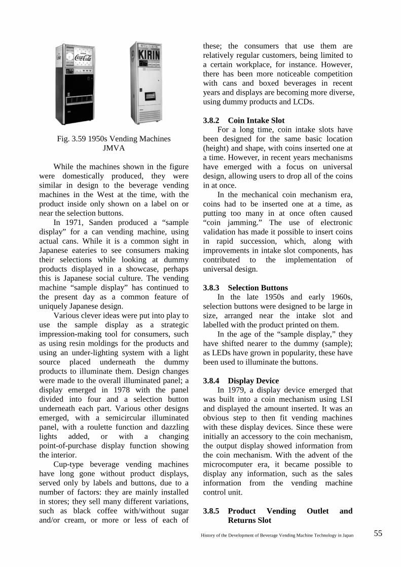
History of the Development of Beverage Vending Machine Technology in Japan 55
Fig. 3.59 1950s Vending Machines JMVA
While the machines shown in the figure
were domestically produced, they were similar in design to the beverage vending machines in the West at the time, with the product inside only shown on a label on or near the selection buttons.
In 1971, Sanden produced a “sample display” for a can vending machine, using actual cans. While it is a common sight in Japanese eateries to see consumers making their selections while looking at dummy products displayed in a showcase, perhaps this is Japanese social culture. The vending machine “sample display” has continued to the present day as a common feature of uniquely Japanese design.
Various clever ideas were put into play to use the sample display as a strategic impression-making tool for consumers, such as using resin moldings for the products and using an under-lighting system with a light source placed underneath the dummy products to illuminate them. Design changes were made to the overall illuminated panel; a display emerged in 1978 with the panel divided into four and a selection button underneath each part. Various other designs emerged, with a semicircular illuminated panel, with a roulette function and dazzling lights added, or with a changing point-of-purchase display function showing the interior.
Cup-type beverage vending machines have long gone without product displays, served only by labels and buttons, due to a number of factors: they are mainly installed in stores; they sell many different variations, such as black coffee with/without sugar and/or cream, or more or less of each of
these; the consumers that use them are relatively regular customers, being limited to a certain workplace, for instance. However, there has been more noticeable competition with cans and boxed beverages in recent years and displays are becoming more diverse, using dummy products and LCDs. 3.8.2 Coin Intake Slot
For a long time, coin intake slots have been designed for the same basic location (height) and shape, with coins inserted one at a time. However, in recent years mechanisms have emerged with a focus on universal design, allowing users to drop all of the coins in at once.
In the mechanical coin mechanism era, coins had to be inserted one at a time, as putting too many in at once often caused “coin jamming.” The use of electronic validation has made it possible to insert coins in rapid succession, which, along with improvements in intake slot components, has contributed to the implementation of universal design. 3.8.3 Selection Buttons
In the late 1950s and early 1960s, selection buttons were designed to be large in size, arranged near the intake slot and labelled with the product printed on them.
In the age of the “sample display,” they have shifted nearer to the dummy (sample); as LEDs have grown in popularity, these have been used to illuminate the buttons. 3.8.4 Display Device
In 1979, a display device emerged that was built into a coin mechanism using LSI and displayed the amount inserted. It was an obvious step to then fit vending machines with these display devices. Since these were initially an accessory to the coin mechanism, the output display showed information from the coin mechanism. With the advent of the microcomputer era, it became possible to display any information, such as the sales information from the vending machine control unit. 3.8.5 Product Vending Outlet and
Returns Slot
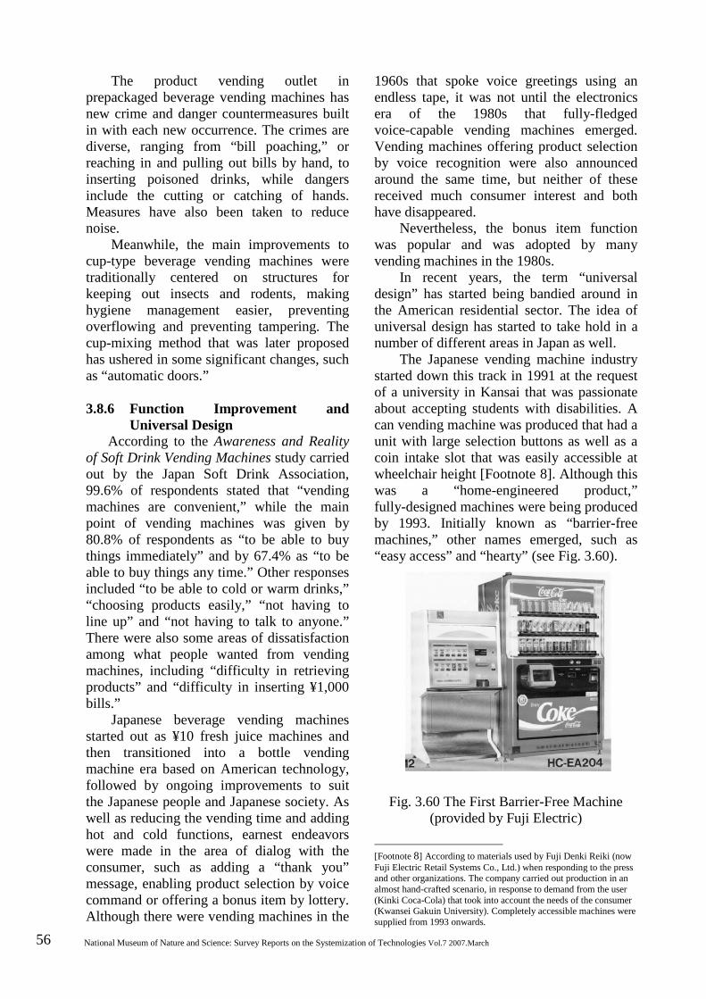
56 National Museum of Nature and Science: Survey Reports on the Systemization of Technologies Vol.7 2007.March
The product vending outlet in prepackaged beverage vending machines has new crime and danger countermeasures built in with each new occurrence. The crimes are diverse, ranging from “bill poaching,” or reaching in and pulling out bills by hand, to inserting poisoned drinks, while dangers include the cutting or catching of hands. Measures have also been taken to reduce noise.
Meanwhile, the main improvements to cup-type beverage vending machines were traditionally centered on structures for keeping out insects and rodents, making hygiene management easier, preventing overflowing and preventing tampering. The cup-mixing method that was later proposed has ushered in some significant changes, such as “automatic doors.” 3.8.6 Function Improvement and
Universal Design According to the Awareness and Reality
of Soft Drink Vending Machines study carried out by the Japan Soft Drink Association, 99.6% of respondents stated that “vending machines are convenient,” while the main point of vending machines was given by 80.8% of respondents as “to be able to buy things immediately” and by 67.4% as “to be able to buy things any time.” Other responses included “to be able to cold or warm drinks,” “choosing products easily,” “not having to line up” and “not having to talk to anyone.” There were also some areas of dissatisfaction among what people wanted from vending machines, including “difficulty in retrieving products” and “difficulty in inserting ¥1,000 bills.”
Japanese beverage vending machines started out as ¥10 fresh juice machines and then transitioned into a bottle vending machine era based on American technology, followed by ongoing improvements to suit the Japanese people and Japanese society. As well as reducing the vending time and adding hot and cold functions, earnest endeavors were made in the area of dialog with the consumer, such as adding a “thank you” message, enabling product selection by voice command or offering a bonus item by lottery. Although there were vending machines in the
1960s that spoke voice greetings using an endless tape, it was not until the electronics era of the 1980s that fully-fledged voice-capable vending machines emerged. Vending machines offering product selection by voice recognition were also announced around the same time, but neither of these received much consumer interest and both have disappeared.
Nevertheless, the bonus item function was popular and was adopted by many vending machines in the 1980s.
In recent years, the term “universal design” has started being bandied around in the American residential sector. The idea of universal design has started to take hold in a number of different areas in Japan as well.
The Japanese vending machine industry started down this track in 1991 at the request of a university in Kansai that was passionate about accepting students with disabilities. A can vending machine was produced that had a unit with large selection buttons as well as a coin intake slot that was easily accessible at wheelchair height [Footnote 8]. Although this was a “home-engineered product,” fully-designed machines were being produced by 1993. Initially known as “barrier-free machines,” other names emerged, such as “easy access” and “hearty” (see Fig. 3.60).
Fig. 3.60 The First Barrier-Free Machine (provided by Fuji Electric)
[Footnote 8] According to materials used by Fuji Denki Reiki (now Fuji Electric Retail Systems Co., Ltd.) when responding to the press and other organizations. The company carried out production in an almost hand-crafted scenario, in response to demand from the user (Kinki Coca-Cola) that took into account the needs of the consumer (Kwansei Gakuin University). Completely accessible machines were supplied from 1993 onwards.
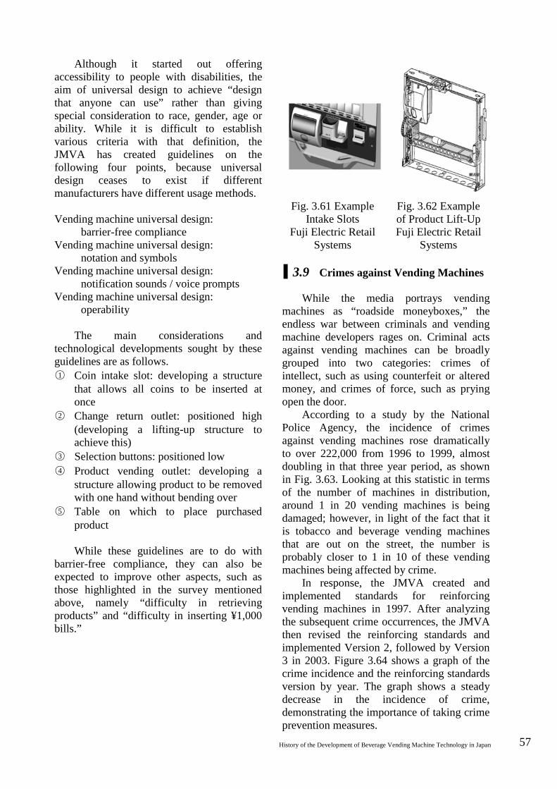
History of the Development of Beverage Vending Machine Technology in Japan 57
Although it started out offering accessibility to people with disabilities, the aim of universal design to achieve “design that anyone can use” rather than giving special consideration to race, gender, age or ability. While it is difficult to establish various criteria with that definition, the JMVA has created guidelines on the following four points, because universal design ceases to exist if different manufacturers have different usage methods. Vending machine universal design:
barrier-free compliance Vending machine universal design:
notation and symbols Vending machine universal design:
notification sounds / voice prompts Vending machine universal design:
operability
The main considerations and technological developments sought by these guidelines are as follows. ○1 Coin intake slot: developing a structure
that allows all coins to be inserted at once
○2 Change return outlet: positioned high (developing a lifting-up structure to achieve this)
○3 Selection buttons: positioned low ○4 Product vending outlet: developing a
structure allowing product to be removed with one hand without bending over
○5 Table on which to place purchased product
While these guidelines are to do with
barrier-free compliance, they can also be expected to improve other aspects, such as those highlighted in the survey mentioned above, namely “difficulty in retrieving products” and “difficulty in inserting ¥1,000 bills.”
Fig. 3.61 Example Intake Slots
Fuji Electric Retail Systems
Fig. 3.62 Example of Product Lift-Up Fuji Electric Retail
Systems
3.9 Crimes against Vending Machines
While the media portrays vending machines as “roadside moneyboxes,” the endless war between criminals and vending machine developers rages on. Criminal acts against vending machines can be broadly grouped into two categories: crimes of intellect, such as using counterfeit or altered money, and crimes of force, such as prying open the door.
According to a study by the National Police Agency, the incidence of crimes against vending machines rose dramatically to over 222,000 from 1996 to 1999, almost doubling in that three year period, as shown in Fig. 3.63. Looking at this statistic in terms of the number of machines in distribution, around 1 in 20 vending machines is being damaged; however, in light of the fact that it is tobacco and beverage vending machines that are out on the street, the number is probably closer to 1 in 10 of these vending machines being affected by crime.
In response, the JMVA created and implemented standards for reinforcing vending machines in 1997. After analyzing the subsequent crime occurrences, the JMVA then revised the reinforcing standards and implemented Version 2, followed by Version 3 in 2003. Figure 3.64 shows a graph of the crime incidence and the reinforcing standards version by year. The graph shows a steady decrease in the incidence of crime, demonstrating the importance of taking crime prevention measures.
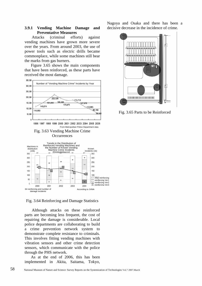
58 National Museum of Nature and Science: Survey Reports on the Systemization of Technologies Vol.7 2007.March
3.9.1 Vending Machine Damage and
Preventative Measures Attacks (criminal efforts) against
vending machines have grown more severe over the years. From around 2003, the use of power tools such as electric drills became commonplace, while some machines still bear the marks from gas burners.
Figure 3.65 shows the main components that have been reinforced, as these parts have received the most damage.
Fig. 3.63 Vending Machine Crime Occurrences
Fig. 3.64 Reinforcing and Damage Statistics
Although attacks on these reinforced parts are becoming less frequent, the cost of repairing the damage is considerable. Local police departments are collaborating to build a crime prevention network system to demonstrate complete resistance to criminals. This involves fitting vending machines with vibration sensors and other crime detection sensors, which communicate with the police through the PHS network.
As at the end of 2006, this has been implemented in Akita, Saitama, Tokyo,
Nagoya and Osaka and there has been a decisive decrease in the incidence of crime.
Fig. 3.65 Parts to be Reinforced
From Metropolitan Police Department data
Number of “Vending Machine Crime” Incidents by Year
After reinforcing reinforcing Ver1 reinforcing Ver2 reinforcing Ver3
According to JVMA
Trends in the Distribution of Reinforced Vending Machines and
the Number of Known Vending Machine Crime Incidents
(Drinks/tobacco) Known
incidents (1k)
64 reinforcing and number of damage incidents
Machines in distribution
(10k)

History of the Development of Beverage Vending Machine Technology in Japan 59
Bibliography [1] “20-Year History of Vending
Machines,” Japan Vending Machine Manufacturers Association, p. 103.
[2] Shin Denki (New Electrical Science), September 2006, Ohmsha, p. 34.
[3] “40-Year History of Sanden Technology,” Sanden Holdings Corporation, p. 49.
[4] “50-Year History of Sanyo Product Development,” Sanyo Electric Co., Ltd., p. 60.
[5] “20-Year History of Vending Machines,” Japan Vending Machine Manufacturers Association, p. 30.
[6] “Tales of Milk Containers New and Old,” Japan Dairy Association, p. 1.
[7] “40-Year History of Tetra Pak Japan.” [8] “50-Year History of Sanyo Electric,”
Sanyo Electric Co., Ltd., p. 802. [9] “40-Year History of Sanden
Technology,” Sanden Holdings Corporation, p. 43.
[10] “Dictionary of Vending Machine Terminology,” Japan Vending Machine Manufacturers Association, p. 19.
[11] “Dictionary of Vending Machine Terminology,” Japan Vending Machine Manufacturers Association, p. 69.
[12] “Dictionary of Vending Machine Terminology,” Japan Vending Machine Manufacturers Association, p. 17.
[13] “Vending Machine Popularization Statistics and Annual Sales Prices (2006 edition),” Japan Vending Machine Manufacturers Association.
[14] Boeki no Nihon (separate issue), May 1999, Nippon Conlux, p. 145.
[15] The Journal of the Institute of Electrical Engineers of Japan, vol. 125, no. 6, p. 361.
[16] The Journal of the Institute of Electrical Engineers of Japan, vol. 125, no. 6, p. 362.
60 National Museum of Nature and Science: Survey Reports on the Systemization of Technologies Vol.7 2007.March
4 Systematization
4.1 Beverage Vending Machine
Development
Figure 4.1 shows the history of beverage vending machines. The beverage vending machine market is divided into four parts for convenience, showing which functions were developed when.
The industry involvement of vending machine manufacturers is shown at the top. The ¥10 juice vending machine, heralded as the start of beverage vending machine industrialization, flourished for around five years, from 1959 to around 1964.
Later, prepackaged beverage vending machines were purchased en masse as a tactical tool in the Coca-Cola Company sales strategy; many manufacturers entered the industry at this starting point. The revision to the Food Sanitation Act in 1961 was followed by the emergence of fully-fledged cup-type vending machines, complete with built-in cup dispensers. At around the same time, specialized operators came on the scene.
The vending machines that appeared on the market at this time were made using licensed technology from the West, prepackaged and cup-type machines alike.
A cup-type sake vending machine came onto the scene in 1963 with a tank on top to store the sake and a mechanism to heat the sake using a heat exchanger before pouring it into the cup. This led to the establishment of several or even dozens of automatic sake bars around the country. This machine had been developed using purely Japanese technology and used a built-in cup. Although it is not shown in Table 4.1, in 1962 the Seibu Group opened an automatic parlor furnished with various kinds of beverage vending machines from overseas, the Coca-Cola Company sales strategy came into play and specialized operators were established, effectively marking this year as the dawning of the modern vending machine era.
In terms of prepackaged beverages, travelling salespeople or “door-to-door
dealers” mainly specializing in vending machine sales and their contents were active from around 1974, thus contributing to an increase in the number of these vending machines in distribution. Since these dealers sold vending machines without brand markings, they came to be known as “blank vendors” or “off-brand vendors.” Although their business rapidly expanded, it was accompanied by increasing contract-related issues; by around 1980, this model of business had all but disappeared. Nevertheless, successive new functions continued to be achieved, including multi-signage, multistage dummy design, “talking vending machines” using synthesized speech and voice-recognizing vending machines.
The specialized operators started out dealing with cup-type vending machines, including hot instant coffee machines, cold drink machines and regular hot coffee machines. The approval to install only cup-type vending machines on site at Expo ’70 signified that much ground had been gained in terms of civic acceptance. The market also expanded with the development of miniature tabletop hot beverage machines and “cup-in-coffee” machines selling individual paper cups with the ingredients inside.
The development of the regular coffee hot and cold machine in 1974 and the multi-flavor hot and cold machine in 1976 meant increased annual business for specialized operators.
The beverage manufacturer market left overseas technology behind in 1971 with the adoption of the “serpentine” column. Although this column shape is thought to have been prototyped in USA, it never gained popularity. Some engineers claim that this was because regulations varied from state to state, meaning that American machines had to be equipped for returnable bottles to make a comeback.
The warm canned coffee machines
History of the Development of Beverage Vending Machine Technology in Japan 61
developed in 1972 were uniquely Japanese. This was followed by the appearance of hot and cold vending machines in 1976, which had two separate storage chambers inside, making it possible to sell hot product in winter, cold products in summer and both hot and cold products in spring and fall, thus they could be used all year round. While various different prepackaged beverage machines appeared to suit different types of beverage containers, in terms of technology development, none could be said to be as unique as the hot and cold machines. Improvements to these machines were simply meeting existing needs, mainly to do with improving product quality.
The dairy manufacturer market first saw the development of vending machines selling bottles of milk for home delivery, followed by vending machines selling milk boxes (Tetra Pak) for workplaces, and then Pure-Pak and Brik-Pak machines, which used different containers. While boxed beverage vending machines are functionally and structurally similar to can vending machines, dairy product vending machines have to conform to storage temperature and sales discontinuation standards under the Food Sanitation Act. More recently there has been an increase in the number of boxed milk products that can be stored at room temperature, as well as an increase in the number of vending machines selling these along with other boxed cold drinks. Technology development in the field of prepackaged beverage vending machines has seen a growing interest in environmental issues, with particular focus on energy-saving technologies and the use of refrigerants and thermal insulation foaming agents that do not contain fluorine.
4.2 Systematization of Money Handling Technology
When consumers buy products over the
counter, they normally select a product they want to purchase, pay the amount corresponding to the price on the product and then receive the product; this is a “deferred payment” process. By contrast, vending machine transactions take place in a sequence
in which the consumer first pays the money, then selects the product and then receives the product; this is a “prepay” process, in which payment is made before purchase.
In the mechanical age before electricity, money handling devices naturally worked on a “prepay” system, as the vending device was operated by the weight and shape of the coins inserted, such as seen in the “holy water dispenser” of 215 BCE and the “automatic postage stamp machine” of 1904.
These kinds of mechanisms are still used today, such as those used in fortune-telling vending machines.
The functions of the coin mechanisms in these money handling devices can be summarized and categorized as follows: first, sorting the inserted coins as genuine or slugs (validation); second, preparing the machine for vending or generating a vending-permitted signal according to the inserted amount (money control); and third, paying out change.
Beverage vending machines experienced significant growth from their industrialization at the end of the 1950s and into the bubble economy that followed. It is no exaggeration to say that earning consumer trust and support for this “prepay system” played a major role in the growth of beverage vending machines.
Figure 4.2 shows the growth process of coin mechanisms, divided between validation devices and changers (change devices and counters/controllers).
Firstly, the greatest change in “validation devices” has been the shift from mechanical to electronic technology, with diversification from using only ¥10 coins to ¥10/¥50 two-coin validation and subsequently three- and four-coin validation systems.
To go into more detail, there are two principles behind mechanical coin validation: the long-used slit system and the cradle system, domestically produced based on imported technology. The first coin validation gate regulates the diameter and thickness of the coin intake slot. Various repeated attempts were made at creating even this minor component, as noted by Percival Everitt in his late-19th-century patent application that the entire vending machine would cease from selling if paper, orange
62 National Museum of Nature and Science: Survey Reports on the Systemization of Technologies Vol.7 2007.March
peel or other miscellaneous material were inserted into the coin slot. The diameter and thickness was checked by the coin intake slot as well as a thickness gauge in both slit system and cradle system; a material properties check was then performed by generating an eddy current in the metal as it passed by a permanent magnet and then changing the rolling trajectory from the braking force. This was the basic technology used for mechanical coin validation in beverage and tobacco vending machines, although various other countermeasures were added to prevent counterfeit or forged money and other tampering. These included edge detectors, hole detectors and cutting devices to cut threads tied to coins. These validation device technologies further developed in keeping with the two- and three-coin systems.
These developments were spurred on by the issuance of ¥50 and ¥100 nickel coins in 1967, rather than any technological advances. Accordingly, the shift to electronic systems came with the four-coin mechanism developed to incorporate the ¥500 coin issued in 1982 (although some early mechanical four-coin systems were also developed).
While electronic systems were incorporated into coin mechanisms quite early on for calculating inserted amounts and controlling change payout, the shift in electronics technology from the LSI era to VLSI and ULSI in the late 1970s prompted companies to start incorporating electronics into coin validation.
Japanese developers needed to improve their three-coin sorting devices (three-way mechanisms) and also incorporate the ¥500 coin into a four-coin sorting device (four-way mechanism). Thus, the mechanical four-coin sorting device came into existence and was marketed until the emergence of electronic coin validation.
Incidentally, Mars Engineering International, a British coin mechanism manufacturer, developed an electronic coin validation system and applied for international basic patent rights.
The company later established Mars Electronics in USA and continued to expand into the American market with electronic coin validation, while Japanese manufacturers
continued developing the technology either through technology partnerships with Mars or by purchasing the basic patent. Mechanical coin validation worked by directly measuring the diameter, weight and thickness of coins and determining the material properties using the eddy current braking principle, meaning that the selection methods and capabilities were about the same for all companies. Electronic validation, however, did not measure the length, weight or other physical properties, instead using a substitute characteristic determination mechanism that looked for changes in oscillation frequency and phase when the coin passed through multiple coils and compared these to a genuine coin template. This meant that the development energy at the core of conventional mechanical technology became centered on analog and digital technology, with a wide range of other technology also becoming essential, such as mechanical technology for designing rolling paths and gates and computer statistical processing technology.
Early electronic validation did not have microprocessors available and were not easy to evolve or flexible to adapt. Later, the adoption of microprocessors assisted in shortening development times and putting upgrades to market.
Next, developments in changers (change devices and counters/controllers) can be broadly categorized into the resinification of mechanical components and the electronification of counters and controllers.
The 1970s saw the emergence of engineering plastics (modified PPOs, trade name Noryl) that were heat-resistant to 100–150˚C, followed by the emergence of high-performance engineering plastics and super heat-resistant engineering plastics and the resinification of metal components, mainly automobile parts.
American beverage vending machine coin mechanisms, which had become the de facto standard in Japan, followed a similar path, with previously zinc die cast casings and functional components being replaced by engineering plastics from around 1973.
Change payout devices evolved from early models with two change tubes (pipes
History of the Development of Beverage Vending Machine Technology in Japan 63
containing coins to be paid out in change) to having four tubes to prevent running out of change. A number of other functions were also achieved, such as replacing the tubes with cassettes for ease of filling and emptying, paying out different denomination coins, paying out multiple coins at once instead of one at a time and a fast payout system. These functions meant incorporating numerous small parts within a confined space; this was made possible through the heat resistance, wear resistance, impact resistance and other special properties of engineering plastics.
These plastics proved their worth in many other ways besides function enhancement, such as reducing an overall weight of 7 kg down to 2 kg and making it possible to cheaply produce complex components, as well as improved maintenance workability, product quality and longevity.
Due to the limitations with mechanical counting by cams and steppers, active initiatives had long been undertaken to achieve electronic counters and controllers. While practical implementation of money counters and change controllers using transistor-type logic circuits had been achieved in the late 1960s, there were problems with product quality and no great leaps had been made in development until the electronics industry entered the age of integrated circuits. Rapid developments were made in electronics technology, with the LSI age following straight after the implementation of ICs. A custom LSI series was finally developed in 1973.
As this series incorporated a number of useful functions, including an inserted money display, multiple price settings and escrow, it significantly improved the functions of the tobacco vending machines in which it was mounted. This epoch-making development in money controllers was the result of collaboration between custom LSI designers (semiconductor manufacturers) and coin mechanism designers (vending machine manufacturers). This set a precedent for development using the combined knowledge and skills for technologies in different industries, something that is now commonplace.
Other peripheral coin mechanism devices
produced included displays using information from the coin mechanism to show the inserted amount or failure information, as well as secondary change devices to prevent change shortages.
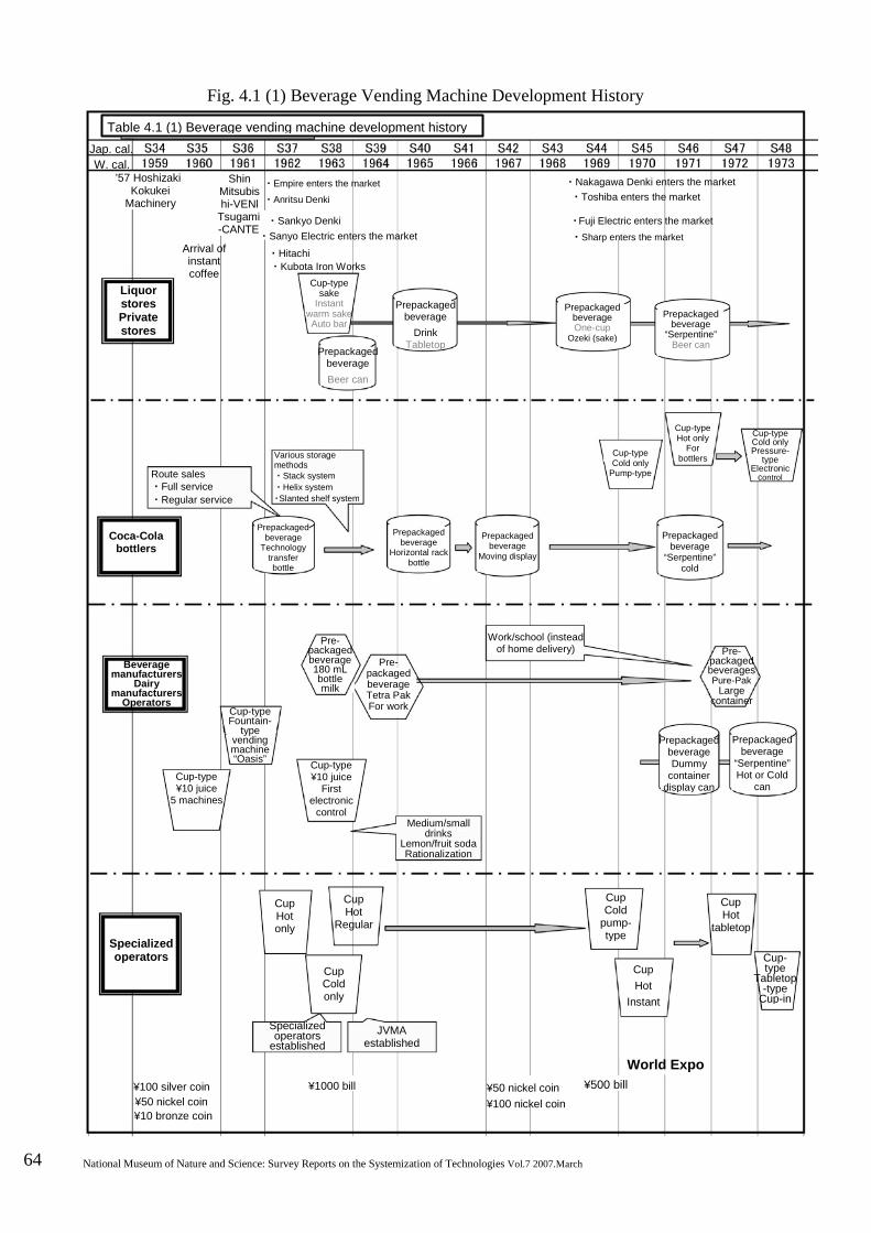
64 National Museum of Nature and Science: Survey Reports on the Systemization of Technologies Vol.7 2007.March
Fig. 4.1 (1) Beverage Vending Machine Development History
・Sankyo Denki
Liquor stores Private stores
Cup-type Cold only
Pump-type
Cup-type Fountain-
type vending machine “Oasis”
Cup-type ¥10 juice
5 machines
Cup-type ¥10 juice
First electronic
control Medium/small
drinks Lemon/fruit soda Rationalization
Cup Hot
Regular
Cup- type
Tabletop -type
Cup-in
Pre- packaged beverages Pure-Pak
Large container
Cup-type Hot only
For bottlers
Cup-type Cold only Pressure-
type Electronic
control
Jap. cal.
’57 Hoshizaki
Arrival of instant coffee
Tsugami -CANTE
・Empire enters the market ・Anritsu Denki
Cup-type sake
Instant warm sake Auto bar
Prepackaged beverage
Drink Tabletop Prepackaged
beverage Beer can
Prepackaged beverage One-cup
Ozeki (sake)
・Nakagawa Denki enters the market
Route sales ・Full service ・Regular service
Coca-Cola bottlers
Various storage methods ・Stack system ・Helix system ・Slanted shelf system
Prepackaged beverage
Technology transfer bottle
Prepackaged beverage
Horizontal rack bottle
Prepackaged beverage
Moving display
Beverage manufacturers
Dairy manufacturers
Operators
Pre- packaged beverage 180 mL bottle milk
Pre- packaged beverage Tetra Pak For work
Work/school (instead of home delivery)
Specialized operators
Cup Hot only
Cup Cold only
Specialized operators
established JVMA
established
¥1000 bill ¥100 silver coin ¥50 nickel coin ¥100 nickel coin
¥500 bill World Expo
Cup Hot
Instant
Cup Hot
tabletop
Cup Cold
pump- type
Prepackaged beverage Dummy
container display can
Prepackaged beverage
“Serpentine” Hot or Cold
can
Prepackaged beverage
“Serpentine” cold
Prepackaged beverage
“Serpentine” Beer can
Shin Mitsubishi-VENl
・Hitachi ・Sanyo Electric enters the market
¥10 bronze coin ¥50 nickel coin
・Fuji Electric enters the market ・Sharp enters the market
・Toshiba enters the market
・Kubota Iron Works
W. cal.
Table 4.1 (1) Beverage vending machine development history
Kokukei Machinery
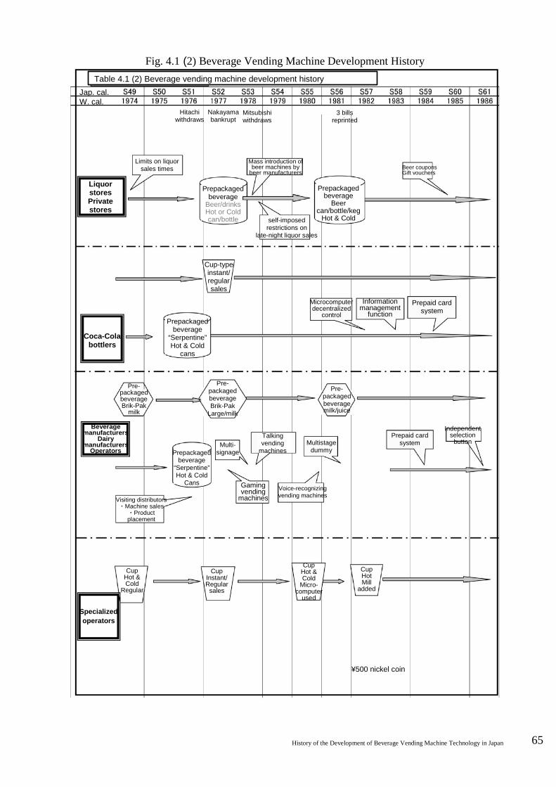
History of the Development of Beverage Vending Machine Technology in Japan 65
Fig. 4.1 (2) Beverage Vending Machine Development History Table 4.1 (2) Beverage vending machine development history
Jap. cal.
Liquor stores Private stores
Limits on liquor sales times
Prepackaged beverage
Beer/drinks Hot or Cold can/bottle
Mass introduction of beer machines by
beer manufacturers
Prepackaged beverage
Beer can/bottle/keg
Hot & Cold
Cup-type instant/ regular sales
Hitachi withdraws
Nakayama bankrupt
3 bills reprinted
Beer coupons Gift vouchers
Coca-Cola bottlers
Prepackaged beverage
“Serpentine” Hot & Cold
cans
Pre- packaged beverage Brik-Pak
milk
Beverage manufacturers
Dairy manufacturers
Operators
Pre- packaged beverage milk/juice
Prepackaged beverage
“Serpentine” Hot & Cold
Cans
Visiting distributors ・Machine sales
・Product placement
Multi- signage
Talking vending
machines
Gaming vending
machines
Prepaid card system
Prepaid card system
Information management
function
Microcomputer decentralized
control
Pre- packaged beverage Brik-Pak
Large/milk
self-imposed restrictions on
late-night liquor sales
W. cal.
Multistage dummy
Voice-recognizing vending machines
Cup Instant/ Regular
sales
Independent selection
button
Cup Hot Mill
added
Cup Hot & Cold
Regular
Cup Hot & Cold
Micro- computer
used
¥500 nickel coin
Specialized operators
Mitsubishi withdraws
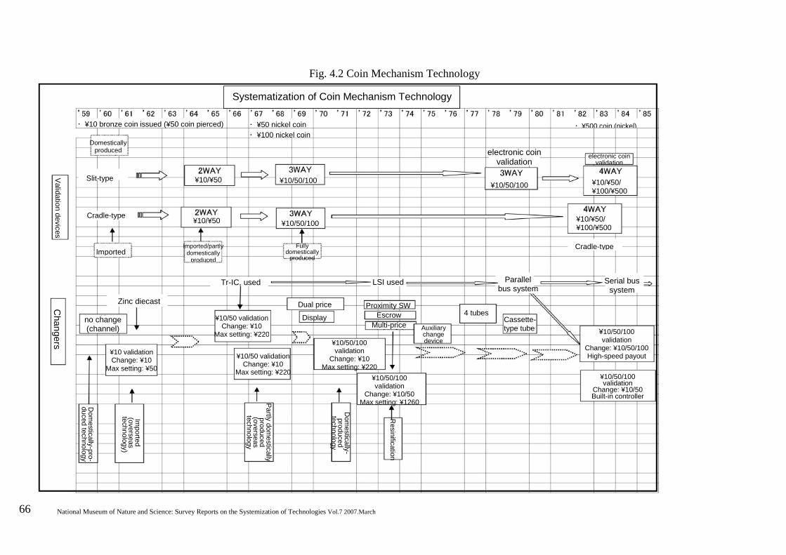
66 National Museum of Nature and Science: Survey Reports on the Systemization of Technologies Vol.7 2007.March
Fig. 4.2 Coin Mechanism Technology
Display
Systematization of Coin Mechanism Technology
・ ¥10 bronze coin issued (¥50 coin pierced)
・ ¥50 nickel coin ・ ¥100 nickel coin
Domestically produced
Slit-type
Validation devices
¥10/¥50 ¥10/50/100
Cradle-type
Imported
¥10/¥50
Imported/partly domestically
produced
¥10/50/100
Fully domestically
produced
Changers
Zinc diecast
no change (channel)
Tr-IC, used
¥10/50 validation Change: ¥10
Max setting: ¥220
¥10 validation Change: ¥10
Max setting: ¥50
¥10/50 validation Change: ¥10
Max setting: ¥220
Dual price
Dom
estically-pro-duced technology
Imported
(overseas technology)
Partly domestically
produced (overseas technology
Dom
estically- produced
technology
Resinification
¥10/50/100 validation
Change: ¥10/50 Max setting: ¥1260
¥10/50/100 validation
Change: ¥10 Max setting: ¥220
Proximity SW Escrow
Multi-price
Auxiliary change device
4 tubes
LSI used Parallel bus system
Cassette- type tube
¥10/50/100 validation
Change: ¥10/50 Built-in controller
¥10/50/100 validation
Change: ¥10/50/100 High-speed payout
Serial bus system
Cradle-type
¥10/¥50/ ¥100/¥500
¥10/¥50/ ¥100/¥500
¥10/50/100
electronic coin validation
electronic coin validation
・ ¥500 coin (nickel)
History of the Development of Beverage Vending Machine Technology in Japan 67
5 Discussion
This chapter endeavors to provide an outline of three decades of vending machine development, from the early days of industrialization of fresh juice vending machines, which spread throughout the country in the 1960s, to the peak vending machine distribution of the 1990s.
Selling beverages by machine is not a new idea. The contributing technologies of money-handling devices and measuring devices are thought to have been developed from the mechanized technology that was popular in Japan in the late 19th and early 20th century. Fresh juice vending machines, such as those mentioned in Hoshizaki company records, started out as electric water coolers with money-handling devices and measuring devices added. Given that this was an era in which electric refrigerators were not yet everyday household items, incorporating cooling technology into a vending machine was truly epoch-making. Nevertheless, these technologies were not what made vending machines into the highly-popular item that they are today. This came about largely due to more advanced technology from countries in the West, the first of which was the development of the Coca-Cola Company’s system on the Japanese market.
The machine that familiarized Japanese society with vending machines was the national railway ticket machine. This manually-operated, single-function machine was developed to coincide with the issuance of the ¥10 bronze coin. This was followed by the printing-type single-function machine, in turn followed by multi-function machines that issued two or more types of tickets. By 1968, all short-distance rail tickets were being issued by multi-function machines, thus introducing consumers to a vending machine society.
Many beverage vending machines were located outdoors, which proves that Japan had a good level of public order. It also indicates that beverage manufacturers expected vending machines to serve as billboards for
promoting brand image, as well as providing a means of “on-the-spot consumption” to consumers who now found themselves with far greater levels of affluence due to very favorable economic conditions. Vending machines continued to spread in distribution, despite gaining a reputation as “roadside cashboxes” and becoming the target for rapidly-rising vending machine related crimes.
While much of the contributing technology came from developed nations overseas, the hot and cold canned beverage vending machines and the dummy display vending machines were definitely the result of epoch-making Japanese technology developments. According to S40-Year History of Sanden Technology, repeated experiments were carried out in harsh conditions of 60˚C with triple protection measures in place; this was a bold challenge indeed. With a few exceptions, most of the 2.3 million prepackaged-beverage vending machines in operation are hot and cold machines. This means that they can operate all year round, thereby increasing vending machine investment efficiency. Partially-electronic function development was used in vending machines since the days of relay sequence control. With the dawn of the microcomputer age in 1983, Sanyo Electric announced a distributed control system combining communications technology with vending machine control technology; this system went on to become the industry standard. It was also licensed in USA, where it became the basis for the standard multi-drop bus (MDB) system in Western vending machines.
The number of beverage vending machines in distribution has stayed fairly constant for the past two decades at around 2.5 million. The number of vending machine shipments was just under 70,000 in 1970 and peaked at over 500,000 in 1989. However, these figures declined after that, sitting at around 350,000 in the past few years.
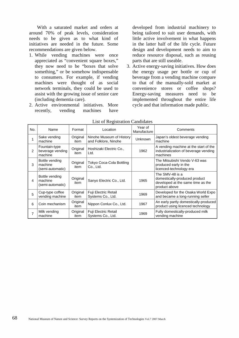
68 National Museum of Nature and Science: Survey Reports on the Systemization of Technologies Vol.7 2007.March
With a saturated market and orders at around 70% of peak levels, consideration needs to be given as to what kind of initiatives are needed in the future. Some recommendations are given below. 1. While vending machines were once
appreciated as “convenient square boxes,” they now need to be “boxes that solve something,” or be somehow indispensable to consumers. For example, if vending machines were thought of as social network terminals, they could be used to assist with the growing issue of senior care (including dementia care).
2. Active environmental initiatives. More recently, vending machines have
developed from industrial machinery to being tailored to suit user demands, with little active involvement in what happens in the latter half of the life cycle. Future design and development needs to aim to reduce resource disposal, such as reusing parts that are still useable.
3. Active energy-saving initiatives. How does the energy usage per bottle or cup of beverage from a vending machine compare to that of the manually-sold market at convenience stores or coffee shops? Energy-saving measures need to be implemented throughout the entire life cycle and that information made public.
List of Registration Candidates
No. Name Format Location Year of Manufacture Comments
1 Sake vending machine
Original item
Ninohe Museum of History and Folklore, Ninohe Unknown Japan’s oldest beverage vending
machine
2 Fountain-type beverage vending machine
Original item
Hoshizaki Electric Co., Ltd. 1962
A vending machine at the start of the industrialization of beverage vending machines
3 Bottle vending machine (semi-automatic)
Original item
Tokyo Coca-Cola Bottling Co., Ltd.
The Mitsubishi Vendo V-63 was produced early in the licenced-technology era
4 Bottle vending machine (semi-automatic)
Original item Sanyo Electric Co., Ltd. 1965
The SMV-48 is a domestically-produced product developed at the same time as the product above
5 Cup-type coffee vending machine
Original item
Fuji Electric Retail Systems Co., Ltd. 1969 Developed for the Osaka World Expo
and became a long-running seller
6 Coin mechanism Original item Nippon Conlux Co., Ltd. 1967 An early partly domestically-produced
product using licenced technology
7 Milk vending machine
Original item
Fuji Electric Retail Systems Co., Ltd. 1969 Fully domestically-produced milk
vending machine

History of the Development of Beverage Vending Machine Technology in Japan 69
6 Conclusion
This study has aimed to systematize the
technological developments of beverage vending machines, the most highly- and widely-distributed of the great diversity of vending machines in existence. This firstly required resources that would provide an understanding of the vending machine industry; secondly, it required an outline of the mechanics of vending machines, so as to provide an understanding of the technology.
Locating technology-related historical materials and surveying the technology proved to be a challenge, as although some records survive in company archives, many original resources have been scrapped and most of the engineers familiar with the technology of the time are now retired. In some cases, it has been purchasing users rather than manufacturers that have kept machines. While some collectors publish their collections on the internet, others such as Tokyo Coca-Cola Bottling have maintained and kept their own machines.
Perhaps a survey of users in different regions should be carried out at some future opportunity.
One difficulty with surveying the technology was the fact that leading manufacturers Mitsubishi Heavy Industries, Ltd., Hitachi, Ltd. and Sanyo Electric Co., Ltd., all of which contributed to the rapid development of the technology, withdrew from the project and were unable to be surveyed.
In closing, the author expresses sincere gratitude to all of those who assisted in this project from the Japan Vending Machine Manufacturers Association, the Ninohe Museum of History and Folklore, Tokyo Coca-Cola Bottling Co., Ltd., Fuji Electric Retail Systems Co., Ltd., Sanyo Electric Co., Ltd., Sanden Holdings Corporation and Nippon Conlux Co., Ltd., as well as all of those who offered their advice through private communication, having retired from company service.
Where drawings and photographs have
been sourced from company materials, the company name or other details have been cited as the source.