Embed Size (px)
Citation preview

History of the SEU Test Facility
In response to the raising demand for testing, the Single Event Facility Group was formalized in 1987 asa consortium of several U.S. Government agencies:
NSA - National Security Agency NASA - National Aeronautic and Space Administration NRL - Naval Research Laboratory USASDC - U.S. Army Strategic Defense Command
with a goal to develop the Single Event Upset Test Facility available to all outside users includinggovernment, industry, and academic institutions. From the beginning the emphasis was given tosimple, efficient, flexible, and user friendly operation with minimum user training and crew requirements,resulting in high data throughput and low cost per data point.
The facility was built in 1987 as a joint project of the Single Event Facility Group and BrookhavenNational Laboratory and became operational in March 1988. The Brookhaven Twin Tandem Van deGraaff accelerator provides the heavy ion beams. At about this time, one of the twin accelerators (serialnumber MP7) had been modified and improved in performance in order to function as a heavy ioninjector for the 30 GeV Alternating Gradient Synchrotron. Since the low energy nuclear physics researchwas discontinued and the heavy ion operation of AGS was carried on for only a small part of each year,there wee large blocks of operating time available for SEU testing. In 2001, the MP7 acceleratorbecame the main injector of the new Relativistic Heavy Ion Collider (RHIC). Since the beam demandfor the RHIC accelerator would not be compatible with the continuous use of the SEU Test Facility, thesecond twin accelerator (serial number MP6) has been upgraded in a similar way as the MP7accelerator a decade ago. This arrangement also necessitated design and installation of a bypassbeamline from the MP6 around the MP7. The MP6 accelerator can now be used by the SEU TestFacility when the MP7 is not available and the facility can operate without major interruptions throughoutthe entire year. The SEU Test Facility is located at the 55° east beam line in Target Room 4, Building901-A.
Page 1
ABC Amber HLP Converter Trial version, http://www.processtext.com/abchlp.html

Over the past years the Brookhaven SEU Test Facility has built a solid reputation in providing thecontrolled environment required for SEU testing of electronic devices and the use of the facility hasbeen steadily increasing. In 1991, the facility was upgraded by replacing the main computer runningunder Rocky Mountain (HP) Basic, rebuilding the positioning stage, and developing a new user friendlyoperating software with pull-down menus, pop-up windows, and mouse support running under MicrosoftDOS. Other systems, such as the vacuum interlock, shutter control, and the photomultiplier high voltagecontrol were redesigned and/or rebuilt a year later. Since 1993 the operating software has beenrunning under Microsoft Windows 3.1 and since 1996 under Microsoft Windows for Workgroups 3.11. Acompletely new software running under Microsoft Windows 98 was completed in 2001. All necessaryinformation to operate the facility can be found in this help file, which superseeds the printed UserGuide, now obsolete.
Page 2
ABC Amber HLP Converter Trial version, http://www.processtext.com/abchlp.html

Beam Quality Control
Single charged negative ions are generated in a sputter-type ion source operated at -150 kV.Preliminary mass selection is performed by an inflection magnet with resolution 2.5 % The magnet isoperated at -120 kV and provided with a hall-probe gaussmeter. The negative 150 keV ions are theninjected into the accelerator contained in a pressure vessel filled with insulating gas (45 % SF6 + 47 %N2 + 8 % CO2) pressurized to about 10 atm. They are accelerated in an evacuated acceleration tube tothe positive high voltage terminal operated at voltages 1 to 14.5 MV, gaining energy 1 to 14.5 MeV.
In the high voltage terminal, the single charged negative ions are converted into multiple chargedpositive ions by passing through a thin carbon stripping foil. The foil strips away several electrons fromthe ions but it is thin enough (typically 5 mg/cm²) to cause a negligible energy loss (less than 0.05 % ofthe final energy for the heaviest ions). The multiple charged positive ions (with a discrete gaussiancharge state distribution) are then accelerated away from the positive high voltage terminal, gainingenergy up to 14.5 MeV/e. A second stripping foil located at 75 % of terminal voltage can be optionallyused to achieve higher charge states and higher energy gain in the last stage of acceleration.
A single charge component is selected by a highly precise double focusing analyzing magnet inconjunction with narrow object and image slits according to its magnetic rigidity (momentum divided bycharge). A cross-field electrostatic and magnetic velocity selector (Wien filter) has been installed infront of the analyzing magnet. This velocity selector acts as a highly effective additional filter, which hasessentially eliminated weak beam contaminants that were occasionally observed in the past. The fieldof this magnet is measured by a nuclear magnetic resonance probe and the magnetic rigidity of theselected component is determined with resolution better than 0.1 %. A computer search is performed toidentify possible beam contaminants and charge states which may generate contaminants with similarmagnetic rigidities are avoided. For further verification, at least three different charge states areselected by varying the terminal voltage. The measured terminal voltages and the componentsrelative intensities are evaluated.
Page 3
ABC Amber HLP Converter T ria l version, http://www.processtext.com/abchlp.html

The selected beam is deflected by the switcher magnet into the 55° east beamline and allowed totraverse a thin multiple scattering gold foil (600 mg/cm² or more). Some ions are scattered into theion-implanted silicon detector, the pulse-height spectrum of which is recorded by a multichannelanalyzer. If different charge components are present they will have different energies and producemultiple peaks. If a single peak is observed at the correct position, a small energy loss in the scatteringfoil is calculated and the beam is sent to the target room 4.
The beam flux can be adjusted by utilizing ion source controls, a variable aperture at the acceleratorentrance, object and image slits settings, scattering foil thickness, and variable beam sweepingamplitudes with the help of a sweeping magnet. Beam uniformity is achieved by multiple beamscattering in the gold foil (about 70 ft upstream from the user test board), by horizontal and verticalsweeping, or by combination of the two methods. Different sweeping frequencies between 5 and 20 Hzare selected for the vertical and horizontal magnets and their lack of synchronization is checked by anoscilloscope.
Page 4
ABC Amber HLP Converter Trial version, http://www.processtext.com/abchlp.html

SEU Test Facility Features
Over 40 different elements including 60 different isotopes over the full range of the periodic table areroutinely accelerated. Most isotopes can be changed in less than 30 minutes and energy changes canbe accomplished in less than 5 minutes.
The beam can be focused down to less than 2 mm in diameter or, on the other hand, easily defocusedand/or swept for uniformly exposing areas as large as 3 cm in diameter.
The beam dosimetry hardware such as detectors, apertures, and beam shutters are installed in aseparate diagnostic vacuum chamber. The beam dosimetry can be performed while the experimentalvacuum chamber is under atmospheric pressure and open.
Evacuation and ventilation of the diagnostic and test vacuum chambers are fully automatic. Evacuationtakes less than 5 minutes, ventilation less than 1 minute.
Several different vacuum feedthrough plates for cable connections between the tester and the deviceunder test are readily available. Other plates can be custom made. Two different plates can beinstalled simultaneously.
The device positioning stage features seven types of motion. The device can be positioned into thebeam by moving in X- and Y-directions (horizontal and vertical coordinates perpendicular to the beam)and rotated around the horizontal axis perpendicular to the test board. The beam diameter can beadjusted by a variable iris aperture. The particle angle of arrival can be changed by tilting the testboard around the vertical axis. Changing of the particle angle of arrival requires placing the device onthe vertical axis of rotation. This is accomplished by moving the device in the Z-direction (horizontalcoordinate parallel to the beam) in order to compensate for the device and/or socket height above theuser test board. The iris aperture tilt is slaved to the board tilt in order to keep the beam spot circular atany particle angle of arrival.
Devices are initially positioned by simulating the beam with visible laser light and by using a joystick.The positions are saved and can be recalled at a later time.
Calculation of LET and range in Si, GaAs, and other target materials is based on Ziegler's Tables.Correction of the beam energy, LET, and range for an energy loss in a composite passivation layer ispossible.
The automatic beam energy and LET monitoring system is calibrated by Am-241 alpha particles andthus independent of the accelerator controls. Hard copies and text data files of the energy spectra areavailable.
The user selected fluence is accumulated for the device under test regardless of the particle angle ofarrival. The flux level can be adjusted in approximately 2 minutes.
A test run can be started and aborted either manually from the keyboard, externally by a user suppliedTTL compatible signal, or by sending an appropriate command from a host computer equipped with aGPIB interface.
Automatic on-line plotting of the upset cross section as a function of effective LET for each device undertest provides the user an early feedback. Hard copies of the on-line plots are available.
Page 5
ABC Amber HLP Converter T ria l version, http://www.processtext.com/abchlp.html

Data management is fully automatic. Data is automatically printed and saved on a file after every testrun. Data files are in ASCII format and can be processed by any text editor (such as Windows Notepador Wordpad) or imported to a spreadsheet program (such as Microsoft Excel).
The SEU Test Facility can be controlled from a host computer as a device on the GPIB interface bus.
The SEU Test Facility application runs under Microsoft Windows 98. It can be executed and control theSEU Test Facility from any computer connected in the Local Area Network (LAN).
The test equipment is supplied by the user.
Page 6
ABC Amber HLP Converter Trial version, http://www.processtext.com/abchlp.html

Test Board
Test board dimensions: 10 x 10 inch normally 18 x 18 inch possible when mounting the test board symmetrically on the frame. 6 x 10 inch working area
The test board must have two appropriately spaced and sized holes for the mounting frame locatingpins and at least four (out of six) holes for No. 6 mounting screws.
Test boards smaller than 10 x 10 inch can be mounted with the help of various custom made mountingadapters. For test boards larger than 10 x 10 inch, any excess dimension over the 10 x 10 inch mountingframe (except at the top) necessitate disabling of the roll angle rotation.
When varying the effective LET by changing the particle angle of arrival (i.e., by tilting the test boardaround the vertical axis), the device under test has to be located on the vertical axis of rotation in orderto stay in the beam at all tilt angles. To compensate for the device and/or socket height above the testboard, it is usually necessary to move the test board backwards in the direction of the beam. Theavailable travel in this direction (and consequently the maximum acceptable height of the test board,socket and the device itself combined) used to be approximately 1 inch. The positioning stage hasbeen equipped with a new test board mounting frame which allows to compensate for the socket anddevice height up to almost 2 inches. The new frame allows less space than the old frame in the back ofthe test board. Test boards with large electronic components and/or connectors mounted on their backside (prepared for the old frame in the past) can still be mounted on the new frame when using two testboard adapters (available at the SEU Test Facility), which essentially convert the new frame to the oldone, but reduce the available travel in the beam direction back to 1 inch.
Page 7
ABC Amber HLP Converter Trial version, http://www.processtext.com/abchlp.html

Page 8
ABC Amber HLP Converter Trial version, http://www.processtext.com/abchlp.html

Cable Connections
Minimum cable lengths: 2-3 ft outside the test vacuum chamber, depending on the connections to your tester 3 ft inside the test vacuum chamber (2 ft when disabling the roll angle rotation)
The connector feedthrough plates are exchangable. Two plates can be used simultaneously.
The connector feedthrough plates can be custom made (see the attached blank plate drawing). ProperO-rings are available at the SET Test Facility. It is recommended that any home made feedthroughplate be sent to the SEU Test Facility for a vacuum leak check prior to your scheduled experiment.
The readily available plates include:
Six male-to-male 40-pin insulation displacement ribbon cable connectors (IDC connectors). Eachfeedthrough consists of two sealed IDC male headers soldered back-to-back and therefore invertsthe pin pattern in the plane of the connector. Simple 40-pin adapters (12 pieces) are available at theSEU Test Facility to invert the pins one more time in the same plane resulting in one-to-one pinpattern. Each adapter consists of a short piece of ribbon cable (about 2 inches) with IDC femaleconnectors on both ends plus another pair of IDC male headers soldered back-to-back.
Four male-to-male 50-pin insulation displacement ribbon cable connectors (IDC connectors). Eachfeedthrough consists of two sealed IDC male headers soldered back-to-back, just like the 40-pinheaders of the above feedthrough plate, and therefore inverts the pin pattern in the plane of theconnector. Simple 50-pin adapters (5 pieces) are available at the SEU Test Facility to invert thepins one more time in the same plane resulting in one-to-one pin pattern.
Eight male-to-male 60-pin insulation displacement ribbon cable connectors (IDC connectors). Eachfeedthrough consists of one sealed IDC male header facing the atmosphere side and its bare pinson the vacuum side. This feedthrough also inverts the pin pattern in the plane of the connector. Simple 60-pin adapters (8 pieces) are available at the SEU Test Facility to invert the pins one moretime in the same plane resulting in one-to-one pin pattern.
Eight 37-pin D-subminiature connector (four of each sex) to 50-pin female ribbon cable IDCconnector adapters are available at the SEU Test Facility. The adapters can be used with theabove 50-pin IDC connector feedthrough and pin pattern reflecting adapters to achieve 37-pinD-subminiature connector one-to-one pin pattern. Male and female 37-pin D-subminiatureconnectors can be place inside or outside the vacuum chamber as necessary.
Six male-to-female 37-pin D-subminiature cable connectors (D-sub connectors). Each feedthroughconsists of two sealed D-sub connectors, male and female, soldered back-to-back. Three maleand three female connectors face the atmosphere side, each with the opposite sex on the vacuumside. The pin pattern of this feedthrough is one-to-one and no adapters are necessary.
One 37-pin and one 25-pin male-to-female D-subminiature connector plus six female-to-female BNCcoaxial connectors. The plate material is aluminum. Shielding connections of all 6 coaxialconnectors are grounded to the vacuum chamber. The male D-sub connectors are outside and thefemale ones inside the experimental vacuum chamber. The pin pattern is one-to-one. Genderchangers of both sexes (male-to-female and female-to-male, one each) for both the 37-pin and25-pin connector are also available. When this feedthrough is left mounted but disconnected, the
Page 9
ABC Amber HLP Converter T ria l version, http://www.processtext.com/abchlp.html

dangling D-sub connectors outside the test vacuum chamber are occasionally caught by thehydraulic scissor table and damaged. Since the feedthrough is not well designed, its use isdiscouraged.
Thirty female-to-female SMA coaxial connectors. The plate material is aluminum. Shieldingconnections of all 30 SMA coaxial connectors are grounded to the vacuum chamber.
Fifteen female-to-female BNC coaxial connectors. The BNC coaxial connectors can be easilychanged to the high voltage SHV coaxial connectors. The plate material is aluminum. Shieldingconnections of all 15 BNC or SHV coaxial connectors are grounded to the vacuum chamber.
Fifteen female-to-female BNC coaxial connectors plus 0.25 inch diameter plastic tubing for coolingwater input and output. The BNC coaxial connectors can be easily changed to the high voltageSHV coaxial connectors. The plate material is aluminum. Shielding connections of all 15 BNC orSHV coaxial connectors are grounded to the vacuum chamber.
Fifteen female-to-female BNC coaxial connectors. The BNC coaxial connectors can be easilychanged to the high voltage SHV coaxial connectors. The plate material is plastic. Shieldingconnections of all 15 BNC or SHV coaxial connectors are insulated from each other and from thevacuum chamber.
Page 10
ABC Amber HLP Converter Trial version, http://www.processtext.com/abchlp.html

Page 11
ABC Amber HLP Converter Trial version, http://www.processtext.com/abchlp.html

Vacuum Requirements
Pumping and venting of both the diagnostic and test vacuum chambers is fully automatic. Pumpingtakes less than 5 min, venting less than 1 min.
The vacuum pressure in the test chamber is typically less than 8E-04 torr at the end of the pumpingsequence and less than 2E-04 torr 10 min later. The vacuum pressure eventually drops bellow 5E-06torr after about three days of pumping.
The vacuum pressure may deteriorate due to outgassing from certain types of aluminum heat sinks andelectrolytic capacitors on the test board. Please note that electrolytic capacitors may also explode orotherwise fail when placed in vacuum.
Page 12
ABC Amber HLP Converter Trial version, http://www.processtext.com/abchlp.html

Laser Beam
The laser beam nearly coincidental with the ion beam serves as a visual aid in positioning the deviceunder test into the invisible heavy ion beam. The laser beam is reflected into the beamline by apermanently mounted reflector prism approximately 1 inch off the beamline center in order not to blockthe heavy ion beam. Using the distance from the reflector to the iris aperture (56 ft) and the distancefrom the iris aperture to the test board (13 inch), the laser beam spot is estimated to be less than 0.02inch (0.5 mm) right of the heavy ion beam spot when looking at the test board down the beamline.
The following information is provided in order to help you in estimating the effects (if any) of the laserbeam on the devices under test:
Laser type: He-Ne Wavelength: 6,320 Å 11,520 Å 33,910 Å Output power: 6 mW 1 mW 1.2 mW Beam diameter: 0.79 mm 0.72 mm 1.88 mm Divergence: 1.0 mrad 1.2 mrad 2.3 mrad
The optical path between the laser and the test board is approximately 60 ± 0.5 ft. Please note that theinfrared components are severely attenuated by the glass viewport and do not reach the test board.
Page 13
ABC Amber HLP Converter Trial version, http://www.processtext.com/abchlp.html

Heavy Ion Beams
The available heavy ion beams with their maximum energies are listed in the following table. Their LETand range values in Si and GaAs are calculated at the maximum beam energies. It is possible to varythe LET by decreasing the ion energy, especially for lighter ions when the range is not a limiting factor.
Ion Max. Energy Range (Si) LET (Si) Range (GaAs) LET (GaAs) [MeV] [µm] [MeV·cm²/mg] [µm] [MeV·cm²/mg] H-1 29 4610 0.0152 2660 0.0118 H-2 29 2710 0.0262 1620 0.0168 Li-7 58 404 0.365 250 0.269 B-11 87 221 1.04 138 0.766 C-12 102 194 1.41 120 1.04 N-14 116 164 1.94 102 1.43 O-16 131 145 2.53 90.8 1.86 F-19 145 123 3.30 79.8 2.43 Na-23 170 105 4.86 69.3 3.51 Mg-24 180 97.7 5.63 61.8 4.14 Al-27 192 90.2 6.68 57.4 4.90 Si-28 203 85.8 7.51 54.6 5.51 P-31 206 76.4 8.85 49.1 6.46 Ion Max. Energy Range (Si) LET (Si) Range (GaAs) LET (GaAs) [MeV] [µm] [MeV·cm²/mg] [µm] [MeV·cm²/mg] S-32 217 73.8 9.75 47.4 7.13 Cl-35 224 68.8 11.1 44.4 8.08 K-39 235 61.3 13.6 39.9 9.90 Ca-40 242 59.0 14.7 38.5 10.7 Sc-45 242 54.4 16.7 35.8 12.0 Ti-48 253 53.6 18.0 35.4 13.0 V-51 253 50.5 19.7 33.5 14.1 Cr-52 264 50.2 20.7 33.3 14.9 Mn-55 264 47.7 22.4 31.9 16.1 Fe-56 270 43.7 24.1 31.2 17.0 Co-59 270 44.7 25.3 30.0 18.1 Ni-58 280 44.6 26.2 29.9 18.8 Cu-63 285 43.7 27.9 29.4 20.0 Ion Max. Energy Range (Si) LET (Si) Range (GaAs) LET (GaAs) [MeV] [µm] [MeV·cm²/mg] [µm] [MeV·cm²/mg] Zn-64 285 42.2 29.4 28.4 21.0 Ga-69 290 41.6 31.1 28.2 22.1 Ge-72 290 40.4 32.8 27.6 23.3 As-75 295 39.9 34.1 27.2 24.2 Se-80 295 38.9 35.8 26.7 25.3 Br-79 305 39.0 36.8 26.7 26.1 Sr-88 305 36.6 41.2 25.3 29.0 Zr-90 315 36.0 43.7 24.9 30.8 Nb-93 313 35.2 45.1 24.4 31.7 Ru-102 320 34.3 49.1 23.9 34.3 Rh-103 330 34.6 50.3 24.1 35.2 Ag-107 345 34.8 52.7 24.2 36.9 Sn-120 340 33.5 56.4 23.6 39.2

Ion Max. Energy Range (Si) LET (Si) Range (GaAs) LET (GaAs) [MeV] [µm] [MeV·cm²/mg] [µm] [MeV·cm²/mg] Sb-121 340 33.0 57.6 23.3 40.0 Te-130 350 33.8 57.7 23.9 40.7 I-127 370 34.6 59.9 24.3 41.7 Tb-159 370 31.4 72.2 22.5 49.5 Ho-165 370 31.1 73.9 22.3 50.5 Ta-181 375 30.5 78.9 21.9 53.7 W-184 375 30.3 79.7 21.9 54.1 Re-187 372 30.1 80.3 21.7 54.4 Os-192 377 30.3 81.0 21.9 54.9 Ir-193 377 30.1 81.9 21.7 55.4 Pt-195 380 30.1 82.8 21.8 56.0 Au-197 390 30.5 83.9 22.0 56.8 U-238 385 29.4 91.0 21.4 60.8
The flux range is 1E+03 to 1E+06 ions/cm²/sec under normal operation. The flux can be reduced to1E+02 ions/cm²/sec or, for some ions, increased to 1E+07 ions/cm²/sec upon request. This shift of theflux range by a factor of 10 requires installation of larger or smaller scintillation detector apertures in thediagnostic vacuum chamber.
The fluence range is 1E+04 to 1E+09 ions/cm² under normal operation with test run times 10 to 1000 sec.The fluence can be reduced to 1E+03 ions/cm² or increased to 1E+10 ions/cm² when installing thenon-standard scintillation detector apertures.
The beam uniformity is better than ± 1 % for lighter ions (such as C-12) and better than ± 15 % for heavierions (such as Au-197) over a 3.0 cm diameter beam spot. Please note that the beam uniformity is muchbetter over a smaller area of a typical electronic device under test.
Page 15
ABC Amber HLP Converter T ria l version, http://www.processtext.com/abchlp.html

A higher flux (1E+06 to 1E+09 ions/cm²/sec, or up to 1E+12 protons/cm²/sec) can be delivered if lowerthan maximum ion energy is adequate. The bank of scintillation detectors and counters has to bereplaced with a set of faraday cups and electrometers for beam dosimetry.
Fluence of 1E+07 to 1E+12 ions/cm² (or up to 1E+15 protons/cm²) can be delivered with test run times 10to 1000 sec when using the faraday cups and electrometers for the beam dosimetry.
The beam diameter is continuously variable from 0.2 to 3.0 cm.
Page 16
ABC Amber HLP Converter Trial version, http://www.processtext.com/abchlp.html

Particle Angle of Arrival
The tilt angle rotation (around the vertical axis) is from -84° to 75° under normal operation. Tilt angle upto -90° is possible.
The roll angle rotation (around the horizontal axis perpendicular to the test board) is from -90° to + 84°under normal operation. Roll angle up to +90° is possible.
The absolute accuracy is better than 0°10', reproducibility better than 0°02' for both angles.
Combination of the two angles makes it possible to hit the device under test from virtually any direction.
The effective linear energy transfer (LET) is continuously variable from 0.015 to about 165 MeV·cm²/mg,taking into account an energy loss in a typical passivation layer (equivalent to about 1 mg/cm² or about5 µm of silicon oxide), by changing the beam isotope (H-1 to Au-197), beam energy, and the particleangle of arrival (tilt angle 0° to 75°), with overlaps between ions.
Page 17
ABC Amber HLP Converter Trial version, http://www.processtext.com/abchlp.html

System Reset
The SEU Test Facility application program is resistant against a computer crash in the sense that allsettings are saved in the application Windows registry key. It always starts in exactly the same state itwas before the crash or before normal closing of the program. However, it is imperative that you clearall system setting to their default values, by means of the Clear_All command on the the first menu (thePositioning_menu) at least once at the beginning of your experiment. This is absolutely the first thing todo before you begin to use the program. Otherwise, the program may be using some settings leftbehind by the previous users and not all parameter values are displayed in the Main_Window.
The Clear_All command does not clear so called vital system setting, such as the enabled steppermotors and absolute encoders, software limits of motion, current dosimetry method, scintillation detectoror current collector apertures, and the silicon detector properties and calibration. These parametershave to be checked and/or changed separately, if necessary
Page 18
ABC Amber HLP Converter Trial version, http://www.processtext.com/abchlp.html

Positioning Stage
Make sure that the hydraulic scissors table has been either pushed all the way in under the test vacuumchamber (the IN sensor is active, i.e. pressed) or it has been pulled all the way out (the cable trayoperated OUT sensor is active, i.e. released). The positioning stage movements are totally disabled ifneither sensor is active, in order to protect the positioning stage from hitting the bottom rim of the testchamber.
Check the positions of all axes of motion in the Positions_area of the Main_Window. If you executed theClear_All command on the the Positioning_menu, and sent all axes of motion to their home positions, allpositions should be zero except for the iris diameter, which should be 1.78 cm (0.70 inch).
Check the enabled stepper motors and enabled absolute encoders using the Enable_Motors andEnable_Encoders commands on the the Positioning_menu. Normally, all stepper motors and allabsolute encoders should be enabled. If you are not going to use some type of motion and if you wantto make absolutely sure that the corresponding axis never moves, for example because it mightdamage your test board or cables, you may disable the stepper motor for that axis. You do not have todisable the corresponding absolute encoder; if the axis does not move, the encoder never reads itsposition. Absolute encoders should be disabled only if they are damaged, in order to allow the SEUTest Facility operation (with reduced reliability).
Generally, you do not have to use the Find_Home command on the Positioning_menu for a positioningstage equipped with the absolute encoders. The command is time consuming and may put stress onyour cables if they are already connected to the test board (especially initializing the tilt angle, rollangle, or both). The Find_Home command is necessary to initialize the absolute encoders, a taskusually performed by the Tandem Van de Graaff personnel. In addition, the tilt and roll angle encoderscan be initialized far more accurately by other means. The tilt angle is initialized with the help of the laserbeam, while a good quality mirror (such as a silicon wafer) is mounted flat on the test board. The rollangle is initialized with the help of a water level. Again. these tasks are performed by the Tandem Vande Graaff personnel. Please note that the Find_Home command must be executed for axes with thedisabled absolute encoders following a cold reboot of the computer (power-off or using the resetbutton) because it resets the motion controller, but it is not necessary following a warm reboot (using therestart option in the Windows shut down dialog box or by the <Ctrl+Alt+Del> key combination). Inaddition, every time an axis with the disabled absolute encoder does not complete a move or fails tomove altogether (for example because the stepper motor power supply is OFF), the Find_Homecommand for this axis must be executed again.
Page 19
ABC Amber HLP Converter Trial version, http://www.processtext.com/abchlp.html

Mount your test board on the positioning stage and the desired cable feedthrough plates(s) on thebottom flange of the test chamber (see Cable_Connections for a list of available feedthrough plates). When mounting a feedthrough plate, clean carefully the surface facing the bottom flange of the testchamber, the O-ring and its groove (use ethanol, tissue wipes, and cotton swabs as necessary), andapply a thin coat of silicon vacuum grease. You may also ask the operators to mount the desiredfeedthrough plates. When using a custom feedthrough plate, please ask the operators to leak check itbefore mounting. Connect all cables between the feedthrough plate(s) and your test board. Make surethe cables have sufficient length for all desired types of motion. If not sure, move the positioning stagewith the help of manual or mouse joysticks (using the Joysticks command on the Positioning_menu) untilthe axis in question hits a limit switch and stops. If you notice any stress on your cables before reachingthe limit switch, stop and record the current position of the axis. Make sure that you never move beyondthat position. Perform this maneuver especially with the tilt angle, and also with the roll angle if you planto use it. Keep the X- and Y-axes in the least favorable position during the maneuver. The test boardcan also move back and forth (Z-axis) to keep the device under test on the vertical axis of rotation whenthe test board is tilted. If you have anything mounted on the back of the test board and if you plan to tiltthe board (and therefore adjust the Z-axis), try to move it all the way back to make sure no componenton your test board is susceptible to damage. Fasten your cables to the positioning stage asnecessary. Use cable ties whenever possible, adhesive tape may outgas and increase the pumpingtime when evacuating the test vacuum chamber.
Please note that raising the test board mounting frame (moving the Y-axis above its home position, i.e.negative) inserts a steel locking pin either in the hydraulic scissors table bottom eye or in the cable traygroove, depending on whether the table is inside or outside of the test chamber. Consequently, it is notpossible to pull the table out or push it in until the Y-axis is lowered, in order to make enough clearancebetween the positioning stage top and the bottom rim of the test chamber.
If your experiment requires tilting or rolling the test board beyond the hardware limits (-84° to +75° for thetilt angle, -90° to +84° for the roll angle), consult the Tandem Van de Graaff personnel. The negative tiltangle limit switch and/or the positive roll angle limit switch can be defeated to allow tilt angle up to -90°and/or roll angle up to +90° with the help of the Ignore_Limits command on the Positioning_menu. Please note that the command is password protected.
Page 20
ABC Amber HLP Converter Trial version, http://www.processtext.com/abchlp.html

Pumping and Venting
Before pumping down the test vacuum chamber, the hydraulic scissors table with the positioning stagemust be lowered, manually pushed under the chamber, and raised again. Make sure that all usercables from the vacuum feedthrough plate(s) exit through the gap between the bottom flange of the testchamber and the user equipment shelf attached to top of the table. Any cables left dangling around thescissors will almost certainly be crushed. Make also sure that no user cables come across thescissors table rail under the user equipment shelf when lowering the table. Carefully push the table allthe way in under the test vacuum chamber until its base hits the IN sensor. If you are unable to push thetable all the way in, make sure that the Y-axis is at its home position or below (zero or positive) and thatthe steel locking pin is withdrawn from the cable tray groove. If not, pull the table out and lower theY-axis with the help of manual or mouse joystick (using the Joysticks command on thePositioning_menu). Raise the table using the <Up> button of the yellow pendant until the chamber is fullyclosed. As soon as you begin to raise the table, the base is held in place by the steel locking pin toprevent you from pulling the table out if not completely lowered. The hydraulic pump automatically turnsoff when the chamber is fully closed.
Use the Vacuum command on the Beamline_menu to pump down the test vacuum chamber bypressing the <Pump> button. If you closed the chamber properly, the roughing pump is turned on andthe SEU Test Facility system waits for a drop in pressure. If the pressure does not drop, the roughingpump is turned off after about 10 sec and an error message appears on the computer monitor. Thepumping sequence takes less than 5 min (usually about 3.5 min) and is fully automatic: After theroughing pump is turned on and the roughing pump valve opens, the chamber is pumped down toapproximately 5E-02 torr. At this pressure, the roughing pump valve is closed and the high vacuumcryogenic pump valve opens. The pressure rather quickly drops below 1E-03 torr, the ionizationvacuum gauge is turned on and the test chamber beamline valve opens. The SEU Test Facilityapplication shuts down the roughing pump and the pump vents itself. The evacuation is now complete.
Use the Vacuum command on the Beamline_menu to vent the test vacuum chamber by pressing the<Vent> button. The SEU Test Facility application moves the X- and Y-axes to their home positions, inorder to prevent the possibility of hitting the positioning stage with the bottom rim of the test chamberwhen pulling the hydraulic scissors table out. If the homing maneuver fails, for example because youturned the stepper motor power supply off using the Motor_Power command on the Positioning_menu,no venting takes place and an error message is displayed. The venting sequence is also fullyautomatic: First, the ionization vacuum gauge is turned off and both the test chamber beamline valveand the high vacuum cryogenic pump valve close. After about 10 sec delay (to allow for safe closing ofthe high vacuum valves), the venting valve opens. During the safety delay, you can change your mindand stop the venting sequence using the <Stop> button in the Progress_box. Please note that theionization gauge is not turned back on (and consequently the test chamber beamline valve staysclosed); you can turn it back on using the Ionization_Gauges command on the Beamline_menu. If youdid not stop the venting sequence, wait for the hissing sound of air flowing into the test vacuum chamberto cease. The ventilation is now complete.
Lower the hydraulic scissors table completely using the <Down> button of the yellow pendant. Do notleave the pendant cable (or any other cable) laying across the scissors table rail. Pull the hydraulicscissors table out far enough until the cable tray operated OUT sensor is released. This arrangementmakes sure that the positioning stage does not hit the bottom rim of the SEU test chamber (or anyvacuum port protruding from the chamber) when you raise the table again. If you cannot pull thehydraulic scissors table out, make sure you lowered it completely, the Y-axis is at its home position orbellow (zero or positive), and the steel locking pin is withdrawn from the eye in the base of the table.
The following figure shows the vacuum system schematic. Both the diagnostic and SEU test vacuumchambers have separate roughing pumps and vent valves, but only the test vacuum chamber isequipped with a cryogenic pump. Consequently, when pumping the diagnostic vacuum chamber, thetest chamber and/or the diagnostic beamline valves must open after closing the diagnostic box
Page 21
ABC Amber HLP Converter T ria l version, http://www.processtext.com/abchlp.html

roughing pump valve. Pumping and venting of both vacuum chambers is controlled by aprogrammable vacuum controller with 12 process control channels. The programmable vacuumcontroller is capable of reading two convectron gauges, CG1 and CG2 (with pressure range 1E+03 to1E-03 torr) and two ionization vacuum gauges, IG1 and IG2 (with pressure range 1E-02 to 1E-10 torr),one pair for each vacuum chamber. Each process control channel can be assigned one vacuumgauge, pressure set point and hysteresis, delay and interval timers, and an external enable signal. Theprogrammable vacuum controller is supplemented by two single convectron gauge controllers andthree single ionization gauge controllers with one process control channel each. The convectrongauges CGA and CGB prevent opening of the roughing pump valves in case the correspondingroughing pump is not on and pumping. The ionization gauges IG3, IG4, and IG5 make sure that thediagnostic, middle, and wall beamline valves do not open unless vacuum is good on both sides of thevalve. The fast valve is en emergency device to stop venting the accelerator in case of a vacuumaccident; the air would travel up the beamline with the speed of sound and the ordinary vacumm valvesare not capable of respnding that fast. The fast valve sencor is a miniature high vacuum ion pump.
Page 22
ABC Amber HLP Converter Trial version, http://www.processtext.com/abchlp.html

Test Board Setup
All device coordinates (the X-, Y-, and Z-coordinates, and the iris aperture diameter) can be enteredand displayed either in centimeters or inches. Use the Linear_Unit command on the Board_menu toselect the unit you prefer. If you are going to use the laser alignment system to find device coordinates(rather than to enter predetermined coordinates manually), the unit is not important and you can keepthe default selection (cm). Use the Find_Limits command on the Positioning_menu menu and press the<View Limits> button in its dialog box to check the limits for the individual axes of motion.
Clear the present board configuration (if any) using the New command on the Board_menu. If youexecuted the Clear_All command on the the Positioning_menu, the board configuration is alreadyempty and you can skip the New command.
Use the Edit command on the Board_menu to add devices to the board configuration and to enter orfind their coordinates. When you are finished, save the board configuration under a new board filename using the Save_As command on the Board_menu, even if you have only one test board. Otherwise, the SEU Test Facility application will not be able to recall the board configuration in case ofa computer crash or if you close and restart the program.
Select the target material of your devices using the Target_Material command on the Board_menu.Most often it will be silicon (which is the default) or gallium arsenide. The SEU Test Facility applicationwill use this target material for the calculation of LET and range of the heavy ion beams.
If you have the proper information (the material and thickness of individual sublayers on top of thedevice sensitive region) from the manufacturer of your devices, you can also build a compositepassivation or dead layer using the Dead_Layer command on the Board_menu. The SEU Test Facilityapplication will then always correct the beam energy, effective LET, and the penetration depth for anenergy loss in the passivation at all tilt angles. Building the dead layer gives you a good on-line pictureof the energy loss and it may save you time when you evaluate your data later on. The maximumeffective LET in the sensitive region under a typical passivation layer (equivalent to about 1 mg/cm², i.e.5 µm of silicon oxide), which can be induced by the heavy ion beams available at the Brookhaven SEUTest Facility, is about 165 MeV·cm²/mg if you require a minimum penetration depth in the sensitiveregion of at least 5 µm.
The SEU Test Facility application keeps track of the total dose accumulated on every device. Sincethe dose is calculated by multiplying the effective fluence and effective LET (or the normal fluence andnormal LET) and transformed to the units of RAD, it depends on the target material for a given beamisotope, energy, and fluence. By default, the dose is calculated in the substrate material of yourdevices selected by the Target_Material command on the Board_menu, but you can select anysublayer of the passivation layer for the dose calculation. Use the <Dose> pushbutton in theDead_Layer dialog box. For example, if you want just to change the dose unit from RAD(Si) toRAD(SiO2), enter the silicon oxide passivation layer of zero thickness and select it for the total dosecalculation.
If you changed the Target_Material and/or Dead_Layer, save the present board configuration again,using the Save command on the Board_menu.
Page 23
ABC Amber HLP Converter Trial version, http://www.processtext.com/abchlp.html

Beam Dosimetry
The above figure shows the diagnostic vacuum chamber schematics. Normally, the heavy ion beam ismonitored by counting pulses from a bank of four plastic scintillation detectors with precisely machinedapertures in front of them. The default aperture area is 0.1 cm² and used for the beam flux from 1E+03 to1E+06 ions/cm²/sec. If you wish to use lower or higher flux, the aperture area can be increased to 1 cm²or decreased to 0.01 cm², respectively, by changing the scintillator aperture mask in the diagnosticchamber. If you need a flux higher than 1E+07 ions/cm²/sec, the heavy ion beam must be monitored bymeasuring beam current in a pair of faraday cups. Check the present dosimetry method (scintillationdetectors and counters or faraday cups and electrometers) by executing the Dosimetry_Methodcommand on the Dosimetry_menu. The beam source (scattering foil or sweeping magnet) is requiredto calculate the inverse square fall-off of the heavy ion beam from the detectors to your test board. Usually, the scattering foil is used with the scintillation detectors and the sweeping magnet with thefaraday cups, but the operators may choose to keep the scattering foil for protons even when thefaraday cups are used, or to help spread the beam of heavier ions with the sweeping magnet evenwhen the scintillation detectors are used. Changes in the Dosimetry_Method dialog box are passwordprotected. Any change has to be accompanied by replacing the corresponding hardware in thediagnostic vacuum chamber, a task performed by the Tandem Van de Graaff personnel only.
The beam can be intercepted by the front and rear shutters mounted on rotary solenoids. The frontshutter opens for beam dosimetry only, both shutters open when irradiating a device. The time requiredfor activation of these shutters is about 80-100 msec. In order to keep the non-uniformity of theaccumulated fluence and the test run time uncertainty caused by this time interval low, the test run timemust be at least 5 sec.
When you perform a test run, the beam is monitored only by the four outside scintillation detectorslocated just outside of the beam area available to the users. When using the faraday cups for the beamdosimetry, the beam is monitored only by the annular faraday cup or collector plate, both geometricallyinferior to the center faraday cup used for the flux measurement. However, the SEU Test Facilityapplication occasionally checks the beam center by rotating in the fifth scintillation detector of the sametype (or using the center faraday cup). The automatic check of the beam center is performed after youchange the beam isotope and/or energy, after you request a flux change by more than the maximumdrift factor (2.0 by default), or after the beam alignment falls below the acceptable level (85 % by default).If everything is all right, the automatic check of the beam center is performed every half an hour. Use theWarning_Levels command on the Dosimetry_menu to make sure the automatic check of the beamcenter is enabled. The default warning levels are carefully selected to alert you quickly about anybeam deterioration while keeping false alarms at a minimum. If you are using an extremely low flux(1E+03 ions/cm²/sec or less) you may consider lowering the minimum acceptable beam alignment toabout 80 % to avoid frequent false alarms caused by random errors of a low pulse count. Although the
Page 24
ABC Amber HLP Converter T ria l version, http://www.processtext.com/abchlp.html

flux profile over the beam area is always flat or convex (never concave), the beam uniformity for lighterions (H-1 to F-19) is usually so good that the beam center pulse count can be occasionally a percent ortwo lower that the outside average pulse count simply because of random fluctuations of the pulsecount. If you are using these light ions, you may consider lowering the minimum acceptable beamcenter from 0 to -5 % to avoid false alarms.
Measure the beam flux using the Measure_Flux command on the Dosimetry_menu. If scintillationdetectors (or a faraday cup on the test board) are used to monitor the beam, you will hear a sharp clickfrom the diagnostic box as the front shutter opens. The flux measurement takes about 5 sec (10 sec ifthe center scintillation detector is in or if faraday cups are used for the beam dosimetry), but you canstop it earlier using the <Stop> button in the command Progress_box. The result of the measurement isthe normal flux (the flux at the normal angle of incidence) and it is displayed in the Beam_area of theMain_window. On the other hand, the effective flux (the flux multiplied by the cosine of the present tiltangle ) is displayed in the Data_area of the Main_window. Whenever you request a flux change,always refer to the normal flux or ask for a flux increase or reduction by a factor. The operators in thecontrol room have no way of knowing what the present tilt angle is.
Measure the beam energy and/or LET if you want to be absolutely sure you have the heavy ion beamyou asked for and it is free of impurities. Use the Measure_Energy_&_LET command on theDosimetry_menu. Please note that the beam energy measured by means of the accelerator analyzingmagnet and supplied by the operators is far more accurate. Also, please note that the LETmeasurements for lighter ions (Li-7 to Ni-58) consistently agree with the LET calculation based onZiegler's Tables, while the LET measurements for heavier ions (Br-79 to Au-197) are consistently 4-8 %higher. After the beam energy spectrum is processed, you can print it for your records or save it with thehelp of the Save_Spectrum_As command on the Dosimetry_menu for later reference and/orprocessing. Saved energy spectra can be converted to text files using the Convert_To_Text commandon the same menu.
If you have doubts about one of the ion-implanted silicon detectors and/or the aluminum foil thicknessused to measure the beam energy and energy loss, use the Alpha_Calibration command on theDosimetry_menu to recalibrate the detector by a permanently installed Am-241 alpha source, one foreach silicon detector.
Page 25
ABC Amber HLP Converter Trial version, http://www.processtext.com/abchlp.html

First Test Run
Before the SEU Test Facility application allows you to make a Test_Run from the Test_menu, severalparameters must be defined:
Select beam isotope and energy using the Ion/Energy command on the Test_menu. Verify theenergy with the operators to make sure that no verbal misunderstanding took place. Use the<Calculate> button in the Ion/Energy dialog box to calculate beam LET and range in the targetmaterial of your devices. If the faraday cups and electrometers (rather than the scintillation detectorsand counters) are used for the beam dosimetry, you also have to enter the ion charge state suppliedby the operators.
Move a device into the beam position using the Move_Device command on the Test_menu or bydouble-clicking the device ID with the left mouse button in the Board_area of the Main_window. If adevice is positioned in the beam, the device ID on the Board_area is highlighted. Check the deviceposition using the Laser command on the Beamline_menu, then turn the laser off.
Enter the desired effective fluence using the Fluence command on the Test_menu; 1E+05 to 1E+07ions/cm² are usually the reasonable values to start with. Please note that what you actually enter isthe effective fluence (the fluence multiplied by the cosine of the present tilt angle ). If the value youentered is too high, the SEU Test Facility application defaults to the maximum possible fluence toprevent the counters from overflowing. The maximum permissible fluence equals to 1E+08 ionsdivided by the scintillation detector aperture area in cm². If the faraday cups and electrometers areused for the beam dosimetry, there is no upper limit for the fluence. Check the estimated time of thenext test run in the Data_area of the Main_window. If the estimated run time is longer than you arewilling to spend on a single test run, reduce the desired effective fluence or ask the operators toincrease the beam flux. If the estimated run time is too short (less than 5 sec) to neglect theuncertainty caused by opening and closing of the beam shutters (about 80-100 msec), increase thedesired effective fluence or ask the operators to reduce the beam flux.
Alternately, you can specify the run time rather than the fluence, but not both. Use the Run_Timecommand on the Test_menu. Execution of the Run_Time command cancels any previouslyexecuted Fluence command vice versa. The last command executed has a check mark on theTest_menu and the corresponding Toolbar button is depressed.
If any of the above parameters are undefined (e.g. the beam isotope, energy, LET, device ID, andeither fluence or run time), an attempt to make a test run will only cause an error message to appear onthe computer monitor.
Enter the title of your experiment using the Test_Title command on the Test_menu This command hasa cosmetic effect only: the test title appears in the Caption_bar of the Main_window, in the header of yourdata file, and on the on-line data plots.
Make sure the next run number is one before you make the first test run. If you executed the Clear_Allcommand on the Positioning_menu, the run number is already one. Otherwise, set it to one using theRun_Number command on the Data_menu.
Open a new data file using the Open command on the Data_menu, otherwise the test run data will beappended to the present data file shown in the Data_area of the Main_window. If the present data filename is happens to be "Untitled.dat" (the default), the SEU Test Facility application will prompt you toopen a new data file after the first test run.
If the internal light in the test chamber is on, turned it off with the help of the Light command on theBeamline_menu. Please note that a de-lidded chip may fail a test when exposed to the light from theSEU test chamber internal lamps even though it passed the same test when exposed to the scattered
Page 26
ABC Amber HLP Converter T ria l version, http://www.processtext.com/abchlp.html

ambient light in the target room.
Reset the device under test using your tester and start a test run the with the help of the Test_Runcommand on the Test_menu. The SEU Test Facility application will start the counters (or initialize theelectrometers, depending on the present Dosimetry_Method) and open both the front and rear beamshutters in the diagnostic box to irradiate the device under test. You can stop the test run before thedesired fluence is accumulated (or before the desired run time elapsed) using the <Stop> button in thecommand Progress_box. The SEU Test Facility application will close both beam shutters, stop thecounters (or electrometers), and report the average effective flux, accumulated effective fluence,elapsed run time, and some other test run related data (such as the effective LET) in the Enter_Upsetsdialog box. You can either enter the number of upsets obtained by means of your tester or discard thetest run using the <Cancel> button. The upset cross section and its uncertainty are immediatelyupdated as you enter the number of upsets. You can recall the dialog box even if you discarded thetest run using the Enter_Upsets command on the Test_menu, but you have to do that before youperform another test run. If you do not discard the test run, the SEU Test Facility application appends adata record to your data file on the hard disk, prints the data record on a line printer, and adds a datapoint to the on-line plot for the device under test. If no on-line plot exists for the device, it is automaticallycreated at this time. The run number is incremented by one and the SEU Test Facility application isready for another test run.
Page 27
ABC Amber HLP Converter Trial version, http://www.processtext.com/abchlp.html

Remote Control
The first and most simple method of the SEU Test Facility application remote control is the TTLinterrupt, which allows you to start and/or stop a Test_Run by applying TTL compatible signals orpulses from the user equipment to the appropriate inputs of the SEU Test Facility. Two separate digitalinputs are provided, each terminated with a BNC coaxial connector, one to start and the other to stop atest run. In order to use the TTL interrupt, one or both inputs must be enabled by the TTL_Interruptscommand on the Control_menu and the appropriate input must be armed. The SEU Test Facilityapplication arms the START input (if enabled) immediately after you press the <OK> button in theTTL_Interrupts dialog box. The START input is disarmed and the STOP input armed (if enabled) whenyou start a test run. The STOP input is disarmed immediately after the test run is completed and theSTART input is armed (if enabled) when you enter the number of upsets. The two inputs are neverarmed simultaneously. Some other commands controlling various beamline devices such as thebeam shutters, beamline valves, faraday cups, etc. may temporarily disarm the START input, but it isautomatically rearmed (if enabled) when the commands are completed and their dialog boxes (if any)closed. It is possible to select the logic levels as either active low or active high, but they have to be thesame for both the START and STOP inputs. The inputs are level sensitive. If the input is enabled, theactive level is latched (and the TTL interrupt generated) if applied for more than 15 µsec. An activelevel on the START input (if enabled and used) should be removed sometimes during the test run,certainly before you enter the number of upsets, otherwise the SEU Test Facility application will startanother test run immediately. Likewise, an active level on the STOP input (if enabled and used) shouldbe removed before you start another test run, otherwise the test run will be stopped immediately.
A relay contact to monitor the test runs by the user equipment is also available. The relay turns on whenboth the front and rear beam shutters open at the start of the test run and it turns off when the beamshutters are closed. The user output cable is connected to the SEU Test Facility shutter control using a4-pin black plastic circular connector available at the SEU Test Facility. The output voltage is 24 VDCand it can be divided and debounced as necessary.
The second, and quite comprehensive method of the SEU Test Facility application remote control ispossible by a host computer over the GPIB interface bus (General Purpose Interface Bus). In order touse the GPIB control, it must be enabled by the GPIB_Host command on the Control_menu. The entireSEU Test Facility then behaves just like another device on your GPIB bus. The SEU Test Facilitycomputer has two GPIB interfaces, one configured as a system controller and used to control its owndevices, the other configured as a non-system controller and used to communicate with the hostcomputer. See the GPIB_Control for a complete description and programming examples and theCommand_types for a list of available commands.
Page 28
ABC Amber HLP Converter Trial version, http://www.processtext.com/abchlp.html

Data Files
From the moment you open a new (or an existing) data file using the Open command on theData_menu, the data management is fully automatic and all test results are saved in that file. You canopen another data file and save all subsequent test results in this new file at any time. You can insertcomment lines following every test run using the Enter_Comment command on the Test_menu. Acomment line begins with an exclamation point, which is automatically inserted in the front of thecomment text.
The data file is an ordinary text file which you can process it with the help of any text file editor. The Editcommand on the Data_menu does just that. You can correct errors, such as an improper experimenttitle, incorrect number of upsets, or a wrong plot symbol. See a sample_data_file for the actual dataformat. In order to reflect any changes you have made in the data file in the on-line plots, use theSearch command on the Data_menu. Please note that the SEU Test facility application uses theaccumulated fluence and number of upsets to recalculate the upset cross section for the on-line plot. You can also use this command to combine data for data for two or more devices in a single plot.
The SEU Test Facility application generates a single print copy of the data file by printing one datarecord following every test run. You can get more print copies using the Print command on theData_menu. The command prints the entire data file or any portion of it. You can also copy the data fileon a floppy disk when your test is completed using the Copy command and then delete the data fileusing the Destroy command on the same menu. Please note that for a better protection againstunauthorized copying of proprietary data, all information on the destroyed data file is completely lostand impossible to recover by various undelete utilities.
Page 29
ABC Amber HLP Converter Trial version, http://www.processtext.com/abchlp.html

On-line Plots
The SEU Test Facility application automatically generates an on-line data plot (upset cross section vs.effective LET) for each device, for which you have made at least one test run and entered the number ofupsets. The on-line plot is created when the first test run for the device is finished and a number ofupsets entered. Results of all subsequent test runs with the same device are added to the plot, onepoint after every test run. The on-line plot is displayed and updated every time a data point is added tothis plot. Data points for zero number of upsets are displayed as upset cross section thresholds, i.e. asif the number of upsets was one and a little down arrow is added to the plot symbol. The default plotscale is linear for the effective LET and logarithmic for the upset cross section, but you can change thatusing the Plot_Scale command on the Data_menu. The default lower and upper bounds for both theeffective LET and the upset cross section are chosen (and adjusted after every test run) so that the newdata point is visible.
You can display any of the available on-line data plots with the help of the View_Plot command on theData_menu, for example, to examine an existing data plot for another device when you move it back tothe beam and before you make another test run. You can also change the present lower and/or upperbounds for the effective LET and/or the upset cross section using the <Set Bounds> button in theView_Plot dialog box, for example, to make the bounds the same for the on-line plots of severaldifferent devices, or to examine some portion of the plot in more details. Hard copies of the on-line dataplots are available using the Hard_Copy command on the Data_menu.
Page 30
ABC Amber HLP Converter Trial version, http://www.processtext.com/abchlp.html

Error Messages
If the SEU Test Facility application cannot execute a command or if the command cannot be executedproperly or completely, an error message box explaining the nature of the error appears on thecomputer monitor. Serious conditions preventing proper operation of the system show a stop sign iconin the error message dialog box, conditions preventing the command execution completely or properlyshow an exclamation point icon. Common examples of errors of the first type (with the stop sign icon)include a serial port being unavailable to the program, device timeout, etc. Common examples oferrors of the second type (with exclamation point icon) include a disabled stepper motor for an axis youare trying to move, incomplete test board move, undefined beam isotope, or desired fluence, no devicein the beam when attempting a execute test run, beamline shutters under operator control, improperlyclosed SEU test chamber when pumping it down, beamline blocked by some obstruction such as aclosed vacuum valve or inserted faraday cup when using the laser, measuring flux, or executing a testrun, etc.
Please read the error messages !!! If you cannot correct the error yourself or if you are not sure that youcan ignore a warning, ask the Tandem Van de Graaff personnel for help.
Page 31
ABC Amber HLP Converter Trial version, http://www.processtext.com/abchlp.html

Device Timeouts
If the SEU Test Facility application cannot communicate with one of its own devices connected to theGPIB bus or to the serial ports, or with the host computer (if any) connected to a separate GPIB bus, adevice timeout message box appears on the computer monitor. The message box identifies thedevice that caused the timeout and its GPIB address or serial port number. You can select one of thethree buttons: <Retry>, <Exit>, and <Cancel>. Use the <Retry> button a few times. If that fails, try to abortthe command that caused the device timeout using the <Cancel> button and execute the commandagain to see if it fails for the second time too. The <Exit> button is used as the last resort only if the SEUTest Facility application is trapped in an infinite loop (usually only during software development). Locate the specified device and make sure it is on. Check the other suggested possibilities (such ascable connected, printer on line, etc.). Most device timeouts can be resolved by recycling the devicepower.
Never recycle power for the vacuum controller, unless you turn off the power for all vacuum valves. Thevacuum controller losing power may, on rare occasions, twitch its process control relays and shortlyopen inappropriate valves. This may cause serious vacuum system failure requiring several hours torecover from. If not absolutely sure how to turn off the power for the vacuum valves, ask the TandemVan de Graaff personnel for help.
Power for all other devices can be safely recycled at any time.
Page 32
ABC Amber HLP Converter Trial version, http://www.processtext.com/abchlp.html

Beam Flux and Alignment
If you receive a low beam alignment warning, try to measure the beam flux and alignment with the helpof the Measure_Flux command on the Dosimetry_menu. If you receive a low or high beam centerwarning, try to rotate the center scintillator in the beam using the Center_Scintillator command on theBeamline_menu before you measure the flux. If you receive the same warning again, ask the operatorsin the accelerator control room (over the intercom) to restore the beam alignment and/or uniformity. Ifthe SEU Test Facility application issues such warnings frequently at an extremely low flux (less than1E+03 ions/cm²/sec), consider lowering the minimum acceptable beam alignment from 85 % to about80 % with the help of the Warning_Levels command on the Dosimetry_menu.
If the beam flux drifts away but the beam alignment stays above the warning level, you will not receiveany warning, but you may notice a considerable increase in the estimated time for the next test run (inthe Data_area of the Main_window. Do not tolerate this condition for long, ask the operators to restorethe desired flux level. Unless your test requires long test runs at a low flux, try to keep the estimated timebetween 10 sec and 1 min. You will probably waste more beam time by making long test runs than byletting the operators take control of the beam shutters for a moment and restore the required flux level.
If you receive an error message that the high voltage on the scintillation detector photomultipliers is off,make sure that the laser is off, the ionization gauge filament in the diagnostic vacuum chamber is notburned or broken, and the gauge is lit. If everything is all right, turn the photomultiplier bias on using theAll_Devices command on the Beamline_menu.
Page 33
ABC Amber HLP Converter Trial version, http://www.processtext.com/abchlp.html

Vacuum Problems
If the SEU Operating system reports that it cannot pump down the test vacuum chamber, make sure youclosed the chamber properly, that the large O-ring is firmly pressed in its groove in the bottom rim of thechamber, and that no cables or other objects are caught between the chamber rim and the bottomflange of the chamber. Then try to evacuate the chamber again.
If the pump-down time takes more than 5 min, make sure that a proper care was observed whenmounting the vacuum cable feedthrough plates to the bottom flange of the SEU test vacuum chamber. The plate surface facing the flange and especially the plate O-ring must be absolutely clean andgreased with special vacuum grease. Custom made vacuum feedthrough plates must be also leakchecked by the Tandem Van de Graaff personnel prior to mounting. Make also sure that the vacuumionization gauge in the SEU test vacuum chamber is properly connected, its filament is not burned orbroken, and the gauge is lit.
Page 34
ABC Amber HLP Converter Trial version, http://www.processtext.com/abchlp.html

Hydraulic Scissors Table
The user equipment shelf attached sideways to the top of the hydraulic scissors table (next to thebottom flange of the test vacuum chamber with the positioning stage) is rated for a load of 200 lb. Do notoverload the shelf. Distribute weight on the shelf symmetrically left and right, otherwise the bottomflange of the test chamber may slightly tilt and the back of the positioning stage may hit the chamberwall as you close it. The scissors table is the weakest in the low position. If you cannot raise the tablebecause of the load, try to help the hydraulics by manually lifting the table while pushing the <Up> buttonof the yellow pendant.
If you cannot raise the hydraulic scissors table inside the test chamber to close it and pump it down,make sure that you pushed the table all the way in until its base hit the appropriate sensor. If you cannotpull the hydraulic scissors table out after venting the test chamber and lowering the table, make sureyou lowered it completely, the Y-axis of the positioning stage is at its home position or lower (zero orpositive), and the steel locking pin released the base of the table.
If you cannot raise the hydraulic scissors table outside the test chamber after venting and pulling thetable out, make sure that you pulled the table all the way out until the cable tray attached to the tablebase released the appropriate sensor. If you cannot push the hydraulic scissors table inside the testchamber, make sure that the Y-axis of the positioning stage is at its home position or lower (zero orpositive), and the steel locking pin is not inserted in the cable tray groove. When the table is outside ofthe test chamber, an active state of the locking pin is indicated by a red light on the chamber front side.
Page 35
ABC Amber HLP Converter Trial version, http://www.processtext.com/abchlp.html

Electrical Noise
A holding torque (about 1/3 of the full torque) is applied to all stepping motors of the positioning stagewhen they are not moving. If your device is failing a test without being exposed to the beam, try totemporarily shut down the power for the stepping motors with the help of the Motor_Power command onthe Positioning_menu. Remember that you should restore the power before you attempt another move. The SEU Test Facility application restores the stepping motor power on demand automatically, afterissuing a warning message.
Make sure that the internal light in test vacuum chamber is off. If not, turn it off with the help of the Lightcommand on the Beamline_menu. Please note that a de-lidded chip may fail a test when exposed tothe light from an internal lamps in the test chamber even if it passed the same test before, whenexposed to the ambient light in the target room.
Avoid running your test equipment cables over any SEU Test Facility display monitors. The monitorsmay cause a significant contribution to the noise pickup.
Page 36
ABC Amber HLP Converter Trial version, http://www.processtext.com/abchlp.html

Main Window
The Main Window of the SEU Test Facility program has a Resizing_border, standard Caption_bar andMenu_bar, optional Toolbar and Status_bar, and a document view window. The document viewwindow is divided into several rectangular areas that show the SEU Test Facility status (beamlinestatus, vacuum pressure, etc.), various parameters set by the user (board configuration, device undertest, target material, beam isotope, energy, range, LET, tilt and roll angles, penetration depth, effectiveLET, etc.), and the basic dosimetry data (normal flux, effective flux, effective fluence, run time, etc.).
The color scheme of the Main Window can be changed according to your esthetical preferences usingthe Colors command on the Control_menu.
Beamline_area
Board_area
Pressure_area
Positions_area
Target_area
Beam_area
Data_area
Control_area
Page 37
ABC Amber HLP Converter Trial version, http://www.processtext.com/abchlp.html

Caption bar
The Caption bar contains the System menu, Test_Title, Minimize box, either the Maximize or Restoreboxes, and the Close button. You can move the Main_window around by dragging the Caption bar withthe left mouse button. Double clicking the Caption bar with the left mouse button has the same effect asclicking the Maximize or Restore boxes. All these task can also be accomplished by executing variousSystem menu commands, even from the keyboard. These features are common to all Windowsapplications and do not require any additional explanation.
Since the Main_window of the SEU Test Facility application has a fixed layout, the Maximize box is notvery useful - the maximized window does not display any more information than the default size window.
By default, the test title is the application name - SEU Test Facility. You can choose a different test titleusing the Test_Title command on the Data_menu.
Page 38
ABC Amber HLP Converter Trial version, http://www.processtext.com/abchlp.html

Menu bar
The Menu bar simply lists all available SEU Test Facility application popup menus. Popup menus canbe opened by clicking one of them with the left mouse button and then moving the mouse left and right toopen another popup menu or up and down to select a menu command. Alternately, you can openpopup menus from the keyboard by pressing the <Alt> key and either the <Enter> key or one of theunderlined mnemonics keys, and then using the <Left> and <Right> direction keys to open anotherpopup menu or the <Up> and <Down> direction keys (or the underlined mnemonics keys) to select amenu command. This type of menu control is common to all Windows applications.
The SEU Test Facility application Menu bar contains the following list of popup menus:Positioning_menuBoard_menuBeamline_menuDosimetry_menuTest_menuData_menuControl_menuHelp_menu
Page 39
ABC Amber HLP Converter Trial version, http://www.processtext.com/abchlp.html

Beamline area
The Beamline area of the Main_window shows the status of most beamline devices located in targetroom 4 portion of the beamline and in the diagnostic box that can be either moved to block/open thebeamline (i.e., the wall, middle, diagnostic box, and test chamber beamline valves, wall and diagnosticfaraday cups, front and rear diagnostic box beam shutter, and the center scintillation detector) or justturned on/off (i.e., the beam tuning, laser, and the photomultiplier bias). The only beamline device notshown in the Beamline area is the diagnostic beam viewer, not used by the SEU Test Facilityapplication for any purpose. Any device blocking the beamline is shown in inverted colors, while anydevice turned on is highlighted. In a quiescent state, the front and rear beam shutters should be closedand, if using the scintillation detectors and counters for the beam dosimetry, the photomultiplier biasshould be on.
Most of these beamline devices (including the diagnostic beam viewer and the test chamber light) canbe individually operated with the help of the All_Devices command on the Beamline_menu. The twoexceptions are the beam tuning and the test chamber beamline valve, which are only sensed by theSEU Test Facility application. The beam tuning is operated manually by the Tandem Van de Graaffoperators in the accelerator control room, while the test chamber beamline valve is operatedautomatically by the vacuum controller. Other beamline devices may be used by the various SEU TestFacility application menu commands. For example, the Laser command on the Beamline_menu closesthe wall beamline valve, turns the photomultiplier bias off, the laser on, and opens both the front and reardiagnostic box shutters. The Measure_Flux command on the Dosimetry_menu opens just the frontdiagnostic box shutter, while the Test_Run command on the Test_menu opens both the front and rearshutters.
When the beam tuning is on (usually in the final stages of the beam setup or when the Tandem Van deGraaff operators are adjusting the beam flux level), the SEU Test Facility application is prevented fromoperating the diagnostic box beam shutters and the center scintillation detector, which are undermanual control of operators in the accelerator control room. It is not a good idea to operate otherbeamline devices either (such as the Laser or the faraday cups), because they may disrupt the beamtuning process.
Page 40
ABC Amber HLP Converter Trial version, http://www.processtext.com/abchlp.html

Board area
The Board area of the Main_window shows the present board file name created by the Save_Ascommand, loaded by the Open command, or or selected from the list of Recent_boards on theBoard_menu.
The Board area also shows the list of device IDs in the current board configuration build by the Editcommand or loaded from the above board file. Except for the standard Windows application controls(such as the Caption_bar, Menu_bar, Toolbar, and the Resizing_border), the Board area the only activearea of the Main_window.
When the number of devices in the present board configuration is more than 10, a horizontal scrollbarappears at the bottom edge of the Board area. You can use this scrollbar to scroll through the boardconfiguration in pages of 9 devices.
The device positioned in the beam is highlighted. You can move other devices into the beam eitherwith the help of the Move_Device command on the Test_menu or double-clicking them with the leftmouse button in the Board area.
Page 41
ABC Amber HLP Converter Trial version, http://www.processtext.com/abchlp.html

Pressure area
The Pressure area of the Main_window shows the vacuum pressure in the test chamber and thediagnostic box. The pressure is monitored by the SEU Test Facility application only for the display inthe Pressure area, otherwise it is not essential for running the program. If the pressure monitoringcauses trouble, is can be stopped by the Monitor_Pressure command on the Beamline_menu. Thepressure values in both vacuum chambers are then replaced with question marks. See theMonitor_Pressure command for details.
Page 42
ABC Amber HLP Converter Trial version, http://www.processtext.com/abchlp.html

Positions area
The Positions area of the Main_window shows the stepper motor DC power supply status (on/off) andthe current positions of all seven axes of motion of the positioning stage.
The stepper motor DC power supply is automatically turned on when SEU Test Facility program startsand automatically turned off when you quit the program. Normally, the status should be on at all times. Ifit causes noise pick-up by the device under test, you can turn this power supply temporarily off beforeexecuting a Test_Run using the Motor_Power command on the Positioning_menu. When yousubsequently try to move the positioning stage by commands such as Move_Device, Effective_LET,Tilt_Angle, or Roll_Angle commands on the Test_menu, the SEU Test application turns the DC powersupply on for the appropriate axes. Since the axes of motion are divided into two batches, eachconnected to one half of the dual power supply, the Positions area may also indicate the power supplystatus on/off or off/on. On the other hand, the Motor_Power always turns both halves on or both off.
Alternately, if the stepper motor DC power supply causes noise pick-up by the device under test, youcan keep it off at all times except during the test board moves. This automatic power supplymanagement can be enable by the Enable_Motors command on the Positioning_menu.
The current positions of the translational axes of motion (X-, Y-, and Z-axes and the iris aperturediameter are given units set by the Linear_Unit command on the Board_menu (cm or inch), while thepositions of the angular axes (tilt, roll, and iris angles) are always given in degrees. If the stepper motorfor a particular axis of motion is disabled by the Enable_Motors command on the Positioning_menu, theaxis position is replaced by the word "disabled".
Page 43
ABC Amber HLP Converter Trial version, http://www.processtext.com/abchlp.html

Target area
The Target area of the Main_window shows the present target material of the devices in the currentboard configuration (silicon, gallium arsenide, etc.) selected by the Target_Material command on theBoard_menu.
The Target area also indicates the absence or presence of a dead layer on top of the device sensitiveregion build by the Dead_Layer command on the Board_menu. If no dead layer is present, the Targetarea shows dead layer "none", otherwise it shows the total thickness of the composite dead layer inunits of mg/cm².
Page 44
ABC Amber HLP Converter Trial version, http://www.processtext.com/abchlp.html

Beam area
The Beam area of the Main_window shows the present beam isotope, beam energy (in MeV), chargestate (if required, i.e., if the faraday cups and electrometers are used for the beam dosimetry), and thebeam LET (in MeV·cm²/mg) and range (in m) in the present Target_Material. These parameters areset by the Ion/Energy command on the Test_menu. The users request the beam isotope and theapproximate beam energy. The actual beam energy and charge state (if required) are obtained fromthe Tandem Van de Graaff operators, and the beam LET and range are usually calculated in theIon/Energy dialog box.
The Beam area also shows the most recent normal beam flux (in ions/cm²/sec), regardless of thecurrent Tilt_Angle, the beam alignment and center-to-ring ratio (when using the scintillation detectorsand counters for the beam dosimetry), or the center-to-collector ratio (when using the faraday cups andelectrometers). These dosimetry parameters are updated upon executing the Measure_Flux orMeasure_Energy_&_LET commands on the Dosimetry_menu and the Test_Run command on theTest_menu.
When using the scintillation detectors and counters for the beam dosimetry, the center-to-ring ratio isupdated only when executing the Measure_Flux command with the Center_Scintillator inserted in thebeam or when the beam center is automatically checked after a test run as required by theWarning_Levels command on the Dosimetry_menu. When using the faraday cups and electrometersfor the beam dosimetry, the center-to-collector ratio is updated after every flux measurement, either bythe Measure_Flux command or when the beam center is automatically checked after a test run.
Page 45
ABC Amber HLP Converter Trial version, http://www.processtext.com/abchlp.html

Data area
The Data area of the Main_window shows the present data file name created or opened by the Opencommand on the Data_menu.
The Data area also shows the parameters under which the next Test_Run command on the Test_menuwould be executed, such as the next test run number, effective beam energy (in MeV), effective LET (inMeV·cm²/mg), penetration depth (in m), effective flux (in ions/cm²/sec), effective fluence (in ions/cm²),and the estimated run time (in hr:min:sec).
The displayed run number is the next test run number. It is cleared to number 1 by the Clear_Allcommand on the Positioning_menu and it can be set to any number between 1 and 9999 by theRun_Number command on the Data_menu. The run number is automatically incremented every timeyou execute the Test_Run command on the Test_menu and enter the number of upsets.
The beam energy, normal LET, and range in the current Target_Material are set by the Ion/Energycommand on the Test_menu. The displayed effective energy is lowered by an energy loss in theDead_Layer (if any). The energy loss depends not only on the dead layer composition and thickness,but also on the current tilt angle set by the Tilt_Angle or Effective_LET commands on the Test_menu. The effective LET and penetration depth are obtained by recalculating the normal LET and range at theeffective energy (instead of at the beam energy) and then adjusting the calculated values for theparticle angle of arrival by dividing resp. multiplying by the cosine of the current tilt angle .
The effective flux is calculated from the normal flux by multiplying by the cosine of the current tilt angle .It is updated simultaneously with the normal flux shown in the Beam_area of the Main_window, i.e., whenyou execute the Measure_Flux and Measure_Energy_&_LET commands on the Dosimetry_menu andthe Test_Run command on the Test_menu.
You can set either the desired effective fluence or the desired run time (but not both) by the Fluence andRun_Time commands, respectively, both on the Test_menu. These parameters are then shown in theData area. If you set the desired effective fluence, the run time is estimated based on the most recentflux measurement. On the other hand, if you set the desired run time, the effective fluence is estimatedbased on the most recent flux measurement. Due to the beam flux fluctuations, the actual run time (if youset the effective fluence) or the accumulated effective fluence (if you set the run time) may be slightlydifferent from the estimated values when you make a Test_Run.
Page 46
ABC Amber HLP Converter Trial version, http://www.processtext.com/abchlp.html

Control area
The Control area of the Main_window shows the status of the two available methods for the remotecontrol of the SEU Test Facility application.
The SEU Test Facility application can be remotely controlled by applying TTL pulses to theappropriate coaxial BNC connector inputs (START and/or STOP) in order to remotely start and/or stopa single test run. When the method is disabled, the Control area shows the TTL interrupt disabled, whenenabled, the the Control area shows the TTL interrupt either START armed, STOP armed, or unarmed. The STOP input can be armed only when executing the Test_Run command on the Test_menu, whilethe START input can be armed only at all other times - the two inputs are never armed simultaneously. See the TTL_Interrupts command on the Control_menu for details.
The SEU Test Facility application can be also remotely controlled by sending appropriate commandsover the GPIB bus with your tester as the system (bus) controller and the SEU Test Facility as a deviceon the bus. This control is far more comprehensive than the control via the TTL_Interrupts. It allows youto remotely control the beamline devices, move the positioning stage, measure the beam flux, performand/or stop test runs, enter upsets, etc. You can also monitor the SEU Test application status byreading back various parameters such as the present device, tilt angle, effective LET, penetrationdepth, fluence, flux, run time, and many others. When the method is disabled, the Control area showsthe GPIB host disabled, when enabled, the Control area shows the GPIB host enabled. See theGPIB_Host command on the Control_menu for details.
Page 47
ABC Amber HLP Converter Trial version, http://www.processtext.com/abchlp.html

Resizing border
The Main_window of the SEU Test Facility application has a resizing border. Since the window alsohas a fixed layout, resizing the window with its Resizing border is not very useful - a larger size windowdoes not display any more information than the default size window and a smaller size window does notdisplay all the information shown in the default size window.
Page 48
ABC Amber HLP Converter Trial version, http://www.processtext.com/abchlp.html

Progress box
The Progress box shows the status of a command in progress. It always contains a brief description ofthe command. In addition, the Progress box may contain a progress gauge and timer with theestimated and elapsed times, a <Stop> button, or both. Complex progress boxes (such as thoseopened by the Measure_Flux command on the Dosimetry_menu or the Test_Run command on theTest_menu) may also show the beam fluence, flux, and a graphical beam alignment.
A progress box with the command description only is usually displayed when the SEU Test Facilityapplication performs some lengthy communication (up to 5 sec) with a remote device or installedhardware.
A progress box with the progress gauge and timer, but without the <Stop> button is usually displayed bycommands that initiate some simple action of a single remote device or installed hardware that issupposed to take a fixed amount of time (up to 10 sec) and then monitor the device to make sure theaction is completed.
A progress box with the <Stop> button is usually displayed by commands that initiate some complexaction of remote devices and/or installed hardware that may take a variable amount of time (from a fewseconds to several minutes) and then monitor the device(s) until the action is completed. If the progressbox contains the <Stop> button, you can stop the command in progress either by using the <Stop>button or by pressing the <Esc> key.
Commands that display a progress box with the <Stop> button are called interruptible commands.These commands can be also stopped by the KILL command send by a host computer controlling theSEU Test Facility application over the GPIB bus. See the GPIB_Host command on the Control_menufor details.
Page 49
ABC Amber HLP Converter Trial version, http://www.processtext.com/abchlp.html

Positioning menu
Enable_Motors... Enable_Encoders...
Find_Home... Find_Limits...Ignore_Limits...
Read_Positions...Zero_Positions...Go_Home...
Page 50
ABC Amber HLP Converter T ria l version, http://www.processtext.com/abchlp.html

Motor_PowerJoysticks...
Clear_AllExit
Page 51
ABC Amber HLP Converter Trial version, http://www.processtext.com/abchlp.html

Board menu
New Open... Save Save_As...Delete...
Edit...VerifyLinear_Unit...
Target_Material...Dead_Layer...Materials...
Page 52
ABC Amber HLP Converter T ria l version, http://www.processtext.com/abchlp.html

Recent_Boards
Page 53
ABC Amber HLP Converter Trial version, http://www.processtext.com/abchlp.html

Beamline menu
Vacuum... Ionization_Gauges... Monitor_Pressure
LaserLightCenter_ScintillatorAll_Devices...
Light_Setup...
Page 54
ABC Amber HLP Converter Trial version, http://www.processtext.com/abchlp.html

Dosimetry menu
Measure_Flux
Simulate_Beam... Warning_Levels... Dosimetry_Method... Exposure_Method...
Measure_Energy_&_LET...
Page 55
ABC Amber HLP Converter T ria l version, http://www.processtext.com/abchlp.html

Alpha_Calibration...
Clear_Spectrum...Open_Spectrum...Save_Spectrum_As...Convert_To_Text...
Page 56
ABC Amber HLP Converter Trial version, http://www.processtext.com/abchlp.html

Test menu
Test_Run Enter_Upsets... Enter_Comment...
Move_Device...Fluence...Run_Time...Ion/Energy...
Effective_LET...Tilt_Angle...
Page 57
ABC Amber HLP Converter T ria l version, http://www.processtext.com/abchlp.html

Roll_Angle...
Page 58
ABC Amber HLP Converter Trial version, http://www.processtext.com/abchlp.html

Data menu
Open...Search... Copy... Destroy...
Edit...Print...Line_Printer...
Test_Title...Run_Number...
View_Plot...Hard_Copy...
Page 59
ABC Amber HLP Converter T ria l version, http://www.processtext.com/abchlp.html

Plot_Symbol...Plot_Scale...
Page 60
ABC Amber HLP Converter Trial version, http://www.processtext.com/abchlp.html

Control menu
Toolbar Status_Bar Colors...
TTL_Interrupts...GPIB_Host...
SpySpy_Setup...
Connect...Disconnect...Autoconnect
Page 61
ABC Amber HLP Converter T ria l version, http://www.processtext.com/abchlp.html

Configuration
Page 62
ABC Amber HLP Converter Trial version, http://www.processtext.com/abchlp.html

Help menu
Help_Topics... Context_Help How_to_Use_Help...
About...
Page 63
ABC Amber HLP Converter Trial version, http://www.processtext.com/abchlp.html

Enable Motors...
The Enable Motors command enables or disables the remote control of stepper motors for theselected axes of motion. You can disable the individual motors if you want to make absolutely sure thatthey do not move if you accidentally try to later on.
When a stepper motor is under the remote control or enabled, the current position of the correspondingaxis of motion is displayed in the Positions_area of the Main_window . When the motor is disabled, theaxis position is replaced by the word disabled.
When a stepper motor is disabled, both the manual and mouse joysticks for the corresponding axis ofmotion are also disabled. This prevents moving the axis accidentally.
When disabling the stepper motor for the tilt angle, the stepper motor for the iris angle is automaticallydisabled as well. On the other hand, the tilt angle stepper motor can be enabled without enabling theiris angle stepper motor.
The information regarding which stepper motors are enabled or disabled for the remote control is notcleared by the Clear_All command.
Since the stepping motor power turned ON at all times in order to maintain some holding torque on thepositioning stage stepping motors is a common source of excessive noise, the Enable Motorscommand also allows you to turn the Motor_Power automatically ON/OFF as necessary for all motionmaneuvers (i.e., for maneuvers executed by the Find_Home, Find_Limits, and Go_Home commands onthe Positioning_menu, Verify command on the Board_menu, Move_Device, Effective_LET, Tilt_Angle,and Roll_Angle commands on the Test_menu, and for positioning devices into the beam bydouble-clicking their name with the left mouse button in the Board_area of the Main_window ).
Automatic turning the Motor_Power ON/OFF does not work for the manual and mouse joysticks . Whenusing the joysticks , you have either disable this option or turn the stepping motor power ON by theMotor_Power command.
Page 64
ABC Amber HLP Converter Trial version, http://www.processtext.com/abchlp.html

Enable Encoders...
The Enable Encoders command enables or disables the remote control of absolute encoders for theselected axes of motion. An absolute encoders should be disabled only if it does not operate properly,for example because of broken or intermittent connections.
When an absolute encoder is under the remote control or enabled, the current position of thecorresponding axis of motion is checked before and after every move of that axis for enhanced systemreliability. When the absolute encoder is disabled, the motion controller has to keep track of the currentaxis position since the controller power-up or reset and the positioning stage initialization by theFind_Home command. Please note that the motion controller is reset by rebooting the computer withthe <Reset> button, but not by rebooting with the <Ctrl+Alt+Del> key combination.
The main motion controller can only keep track of attempted maneuvers, but it has no means to checktheir success. Therefore, the current positions for the axes with disabled absolute encoders, asreported by the motion controller, may be incorrect after an attempt to move fails, for example becauseof no power for the stepper motor or because the motor stalls. However, it is possible to operate theSEU Test Facility application for extended periods of time with some absolute encoders disabled.
The absolute encoders are necessary for the operation of the manual joysticks. Each manual joystickis actually a separate two-axis motion controller. The main motion controller is not aware of themaneuvers performed with these auxiliary joystick motion controllers and therefore it cannot keep trackof the current positions of the affected axes. During and after every joystick maneuver, the currentpositions of the affected axes must be read with the help of the absolute encoders and loaded into themain motion controller. The SEU Test Facility application monitors the activity of the manual joysticksand performs this task automatically and it also automatically disables the manual joysticks for the axesof motion with the disabled absolute encoders.
Since the joystick maneuvers are essential for editing the present board configuration by the Editcommand on the Board_menu , the manual joysticks for the axes with the disabled absolute encodershave to be simulated by mouse joysticks available in the Joysticks dialog box and also in variousdialog boxes opened by the Edit command.
The information regarding which absolute encoders are enabled or disabled for the remote control is isnot cleared by the Clear_All command.
Page 65
ABC Amber HLP Converter Trial version, http://www.processtext.com/abchlp.html

Find Home...
The Find Home command finds the home (zero) positions for the selected axes of motion. Only theaxes with the stepper motors enabled by the Enable_Motors command can be selected for finding theirhome positions. By default, no axis is selected for the find home maneuver.
Each selected axis moves at first in its positive direction at one fourth of its normal velocity until itspositive limit switch, identical with its home switch, is tripped. Since the position offset of the positive(home) limit switch is known, this offset is now loaded into the motion controller. When the positive(home) limit switches for all selected axes are found, all axes move back to their home (zero) positionsat their normal speed. You can always stop the move before it is completed by pressing the <Stop>button in the Progress_box displayed during the move.
Following the find home maneuver for the selected axes, you have to reset the corresponding absoluteencoders to make them read zero positions. The new position offsets can be saved in their non-volatilememory, so that they are not lost on power-off. This requires entering a password known to the TandemVan de Graaff personnel only. See the Zero_Positions command for the Corresponding dialog box. Tosee the present offsets from the positive (home) limit switches, use the <View offsets> button. Changingthe present offsets requires entering the password as well.
The find home maneuver is essential for the proper operation of almost any automatic motion controlsystem after a reset or power-up. However, it is redundant for the SEU Test Facility positioning stageequipped with the absolute encoders, as long as they are enabled for the remote control and properlyinitialized. Instead of going through the find home maneuver after a computer reset or power-up, the
Page 66
ABC Amber HLP Converter T ria l version, http://www.processtext.com/abchlp.html

current axis positions can be simply read by the absolute encoders and loaded into the motioncontroller.
Users are not allowed to execute the Find Home command for the tilt and/or roll angles. These twoaxes of motion can (and should) be calibrated with a far better accuracy than the fixed offsets from theirpositive (home) limit switches with the help of Zero_Positions command. If the command is executed forthe tilt and/or roll angles, the positioning stage must be watched and the maneuver stoppedimmediately if anything goes wrong. For example, a failure of the positive (home) limit switch to trip cancause a heavy damage to the positioning stage. In addition, if the user cables are too short (less thenabout 3 ft.), they can damage connectors on the vacuum feedthrough plates and on the user test board.
Page 67
ABC Amber HLP Converter Trial version, http://www.processtext.com/abchlp.html

Find Limits...
The Find Limits command finds either the positive or negative limit switch positions for the selectedaxes of motion. Only the axes with the stepper motors enabled by the Enable_Motors command can beselected for finding their limit switch positions. By default, no axis is selected for the find limitsmaneuver.
Each selected axis moves at first in its positive or negative direction at one fourth of its normal velocityuntil its positive or negative limit switches are tripped. When the limit switches for all the selected axesof motion are found, the current positions are read by the absolute encoders, and all axes then moveback to their home (zero) positions at their normal speed. You can always stop the move before it iscompleted by pressing the <Stop> button in the Progress_box displayed during the move.
Following the find limits maneuver of the selected axes, the new software limit positions are displayed.Please note that the software limits are slightly reduced (closer to the home positions) than positions ofthe actual limit switches. This arrangement protects the limit switches from being tripped frequently. The difference amounts to approximately 0.05 cm for the translational axes and 0.1° for the rotationalaxes. You have to accept the new software limits so that they are not lost on power-off. This requiresentering a password known to the Tandem Van de Graaff personnel only. To see the present softwarelimits, use the <View limits> button.
Page 68
ABC Amber HLP Converter T ria l version, http://www.processtext.com/abchlp.html

Users are not allowed to execute the Find Limits command for the tilt and/or roll angles. If the commandis executed for these two axes, the positioning stage must be watched and the maneuver stoppedimmediately if anything goes wrong. For example, a failure of the positive or negative limit switches totrip can cause a heavy damage to the positioning stage. In addition, if the user cables are too short(less then about 3 ft.), they can damage connectors on the vacuum feedthrough plates and on the usertest board.
Page 69
ABC Amber HLP Converter Trial version, http://www.processtext.com/abchlp.html

Ignore Limits...
The Ignore Limits command allows you to move the tilt angle axis up to -90° by ignoring its negative limitswitch and/or the roll angle axis up to +90° by ignoring its positive limit switch. The feature is enabled byentering a password known to the Tandem Van de Graaff personnel only. Ask the operators forassistance if moving to any of these angles is required for your test setup. No password is necessaryto disable this feature.
The limit switches are not ignored until a move beyond the software limit is attempted using theTilt_Angle and/or Roll_Angle commands on the Test_menu menu and the attempt is confirmed onemore time by the user. The operation of the limit switches is restored immediately following the move. They are ignored again if another move beyond the software limits is attempted and confirmed. Whenany of these angles is outside of the limit switch range, both the manual and mouse joysticks for thecorresponding axis are disabled.
Never use the Zero_Positions command for the tilt and/or roll angles when their current positions areoutside of the limit switch range. A subsequent move of the affected axis in a wrong direction can causea heavy damage to the positioning stage. Please note that it is never necessary, even for the tilt angle. Since cosine of 90° is zero, it is ignored in the calculation of the effective LET, penetration depth,effective flux, and effective fluence, resulting in values identical to those for 0° tilt angle.
Page 70
ABC Amber HLP Converter Trial version, http://www.processtext.com/abchlp.html

Read Positions...
The Read Positions command reads the current positions for the selected axes of motion. Thepositions can be reported only for the axes with their absolute encoders enabled by theEnable_Encoders command. However, positions for axes with the stepper motors disabled by theEnable_Motors command are not displayed - their positions are replaced by the word disabled.
The position of each selected axis is first read by the corresponding absolute encoder and then loadedinto the motion controller. Depending on the number of the selected axes, the Read Positionscommand may take up to 2 sec to complete. By default, all axes with the absolute encoders enabledare selected for reading their positions.
The SEU Test Facility program reads the positions before and after every move. It is also capable ofdetecting motion performed by the manual joysticks and read the corresponding absolute encodersautomatically. Consequently, the displayed positions are always correct (as long as all the absoluteencoders are enabled) and the command is redundant. Execute the Read Positions command only ifyou are in doubt about the displayed current positions.
Page 71
ABC Amber HLP Converter Trial version, http://www.processtext.com/abchlp.html
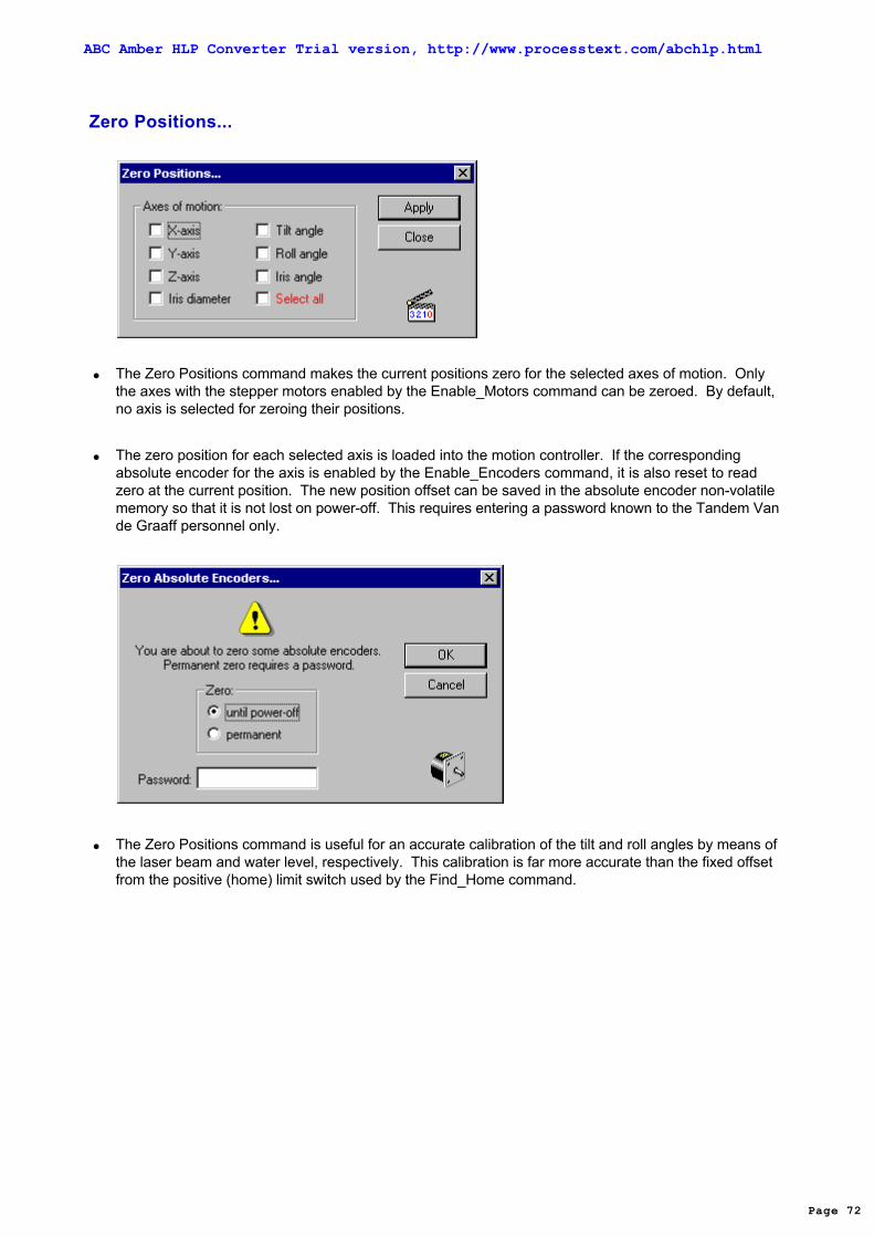
Zero Positions...
The Zero Positions command makes the current positions zero for the selected axes of motion. Onlythe axes with the stepper motors enabled by the Enable_Motors command can be zeroed. By default,no axis is selected for zeroing their positions.
The zero position for each selected axis is loaded into the motion controller. If the correspondingabsolute encoder for the axis is enabled by the Enable_Encoders command, it is also reset to readzero at the current position. The new position offset can be saved in the absolute encoder non-volatilememory so that it is not lost on power-off. This requires entering a password known to the Tandem Vande Graaff personnel only.
The Zero Positions command is useful for an accurate calibration of the tilt and roll angles by means ofthe laser beam and water level, respectively. This calibration is far more accurate than the fixed offsetfrom the positive (home) limit switch used by the Find_Home command.
Page 72
ABC Amber HLP Converter Trial version, http://www.processtext.com/abchlp.html

Go Home...
The Go Home command moves the selected axes of motion to their home (zero) positions. Only theaxes with the stepper motors enabled by the Enable_Motors command can be moved to their homepositions. By default, all axes with enabled stepper motors are selected for moving to their homepositions.
You can always stop the move before it is completed by pressing the <Stop> button in theProgress_box displayed during the move.
Before you vent the SEU test chamber and pull the positioning stage outside, the X- and Y-axes areautomatically moved to their home positions in order to protect the positioning stage from hitting thebottom rim of the chamber, when you pull it out. If, outside of the SEU test chamber, you move the testboard up, for example by the Y-axis joystick or by selecting a device with the negative Y-coordinatefrom the present board configuration displayed in the Board_area of the Main_window , a steel pin isautomatically inserted into the cable tray groove in order to protect the positioning stage from hitting thebottom rim of the chamber, when you push it in. Simultaneously, a red light on the test chamber sidewall is turned on. In this case, you should execute the Go Home command at least for the X- and Y-axesbefore pushing the positioning stage in and pumping the test chamber down. Otherwise, the steel pin isnot withdrawn from the groove, preventing to push the positioning stage underneath the test chamber. Excessive force of momentum may permanently bent the pin.
Page 73
ABC Amber HLP Converter Trial version, http://www.processtext.com/abchlp.html

Motor Power
The stepper motor DC power supply is automatically turned on when the SEU Test application startsand automatically turned off when you quit the program.
The stepper motor drivers maintain a holding torque on all stepper motors when the motors are in astationary state. The holding torque power may interfere with the device under test operation due tosome noise pickup. If any noise pickup is observed, the Motor Power command allows you to turn thestepper motor power off for testing the device operation with your tester and for executing test runs.
When the power is on, the Motor Power command on the Positioning_menu is checked and thecorresponding Toolbar button depressed. The power status is also shown in the Positions_area of theMain_window .
The stepper motors are divided into two batches for their DC power. The motors for the four devicecoordinates (the X-, Y-, Z-coordinates and the iris diameter) are in the first batch, while the motors for theangles (the tilt, roll, and iris angles) are in the second batch. If you attempt to move the positioning stagewith the stepper motor power off, the SEU Test Facility program issues a warning, turns the power on forthe appropriate stepper motor batch and completes the move. Normally, the Motor Power commandtoggles the stepper motor power for both batches simultaneously. It turns the power off if the power is onfor at least one batch.
Page 74
ABC Amber HLP Converter Trial version, http://www.processtext.com/abchlp.html

Joysticks...
The Joystick command allows you to simulate the manual joysticks. The joystick simulator looks like alarge button with a little black square in its center. Each of the four tabs in the Joystick dialog box controla pair of axes, just like the manual joysticks. If you wish to move only one axis, you can temporarilydisable the other one in the pair. To move the single axis or the axis pair, drag the little black squarewith the computer mouse. The axis speed is proportional to the little black square deflection, again, justlike for the manual joysticks. Please note that the manual joysticks are also equipped with switches thatallow you to select the velocity range as high, medium, or low.
Each manual joystick is actually a separate two-axis motion controller. The main motion controller isnot aware of the maneuvers performed with these auxiliary joystick motion controllers and therefore itcannot keep track of the current positions of the affected axes. During and after every joystickmaneuver, the current positions of the affected axes must be read with the help of the absoluteencoders and loaded into the main motion controller. The SEU Test Facility application monitors theactivity of the manual joysticks and performs this task automatically and it also automatically disablesthe manual joysticks for the axes of motion with the disabled absolute encoders. Since the manualjoysticks must be disabled for the axes of motion with the corresponding absolute encoders notenabled by the Enable_Encoders command, the joystick maneuvers for these axes should beperformed with the mouse joysticks. The mouse joysticks remain operational even for the axes withtheir absolute encoders disabled. Maneuvers performed with the mouse joysticks are executed by themain motion controller and the absolute encoders are therefore not necessary to keep track of thecurrent positions.
Page 75
ABC Amber HLP Converter Trial version, http://www.processtext.com/abchlp.html

Clear All
The Clear All command clears or resets to their default values all user settings of the SEU Test Facilityprogram. This is the first command you should execute before starting to use the program. The usersettings include:
the board configuration and board file name, the target material of the devices or samples and their dead layer (if any), the linear unit is set to centimeters. no tilt and/or roll angle limit switches are ignored, the beam isotope, energy, linear energy transfer (LET), and the range, the last measured flux, beam alignment, and the center-to-ring ratio, the last time of the beam center check, the beam beam quality warning levels for beam alignment, center-to-ring and the flux drift, the frequency of checking the beam center is set to automatic, the desired effective fluence or test run time, the test run termination is set to be done by reaching the desired effective fluence, the data file name, test title and the run number, the plot symbol and plot scale, all on-line data plots are erased, any remote control by the TTL interrupts and/or GPIB host is disabled.
After executing the Clear All command, the previous user settings are completely lost and impossible toretrieve. On the other hand, various hardware settings of the SEU Test Facility program are neithercleared nor reset. They must be explicitly changed, if necessary, by the corresponding menucommands, usually after the equipment is mounted, connected, tested and/or calibrated. Thehardware settings include:
the enabled stepper motors and absolute encoders, the most recent values of all limit switch positions and home position offsets from the positive (home)
limit switches, the dosimetry method including the beam scattering method (scattering foil or sweeping magnets),
detector type (photomultipliers with scintillators or faraday cups), and aperture area(s). the exposure method (single device or area scans), the silicon detector properties (resistivity and nominal bias), material of the energy loss foil, and the
detector and foil calibration (calibration constant and its uncertainty, foil thickness and itsuncertainty),
the line printer and plot monitor.
The Clear All command also turns off the laser beam, chamber light, and closes all beam shutters if anyof these devices were activated. Then the command deletes all on-line plots and attempts to home allaxes of motion with the enabled stepper motors. You can reject deleting the plots and/or cancel thehoming maneuver. If you cancel the homing maneuver, no axis is moved and no axis position is clearedeither.
Page 76
ABC Amber HLP Converter Trial version, http://www.processtext.com/abchlp.html

Exit
The Exit command terminates the SEU Test Facility program.
If you have made changes in the present board configuration and did not save it using either the Saveor Save_As commands, you will receive a prompt to save it now, before the program exits.
Page 77
ABC Amber HLP Converter Trial version, http://www.processtext.com/abchlp.html

New
The New command allows you to clear the present board configuration displayed in the Board_area ofthe Main_window . You should use the New command before you start editing a new boardconfiguration from the scratch by the Edit command.
If you have made changes in the present board configuration and did not save it using either the Saveor Save_As commands, you will receive a prompt to save it now, before it is cleared.
Page 78
ABC Amber HLP Converter Trial version, http://www.processtext.com/abchlp.html

Open...
The Open command allows you to retrieve a previously saved board configuration by opening anexisting board file and display it in the Board_area of the Main_window as the present boardconfiguration.
The file list is filled by files in the ...\Boards subfolder with the *.brd file filter for board files. There is nodefault file name. You either have to type it in or you can select an existing board file from the file list. When typing in the board file name, no file extension has to be included. If you omit the extension, thedefault board file extension .brd is used.
If you do not remember the board file name of the board configuration you wish to retrieve, try to sort theboard files by date in the descending order. The topmost file or a file close to the top are the most likelychoices.
If you have made changes in the present board configuration and did not save it using either the Saveor Save_As commands, you will receive a prompt to save it now, before it is replaced by another boardconfiguration.
Page 79
ABC Amber HLP Converter Trial version, http://www.processtext.com/abchlp.html

Save
After you have made changes in the present board configuration, you can (and should) save it in aboard file. The Save command saves the present board configuration displayed in the Board_area ofthe Main_window in the present board file, so that you do not have to type in the file name or select fromthe file list. The present board file name is set by the Save_As command and it is also shown in theBoard_area .
If the present board file name is Untitled.brd, the Save command defaults to the Save_As command.
The board file is saved in an internal binary format recognized only by the SEU Test Facility program.
If you have made changes in the present board configuration and did not save it using either the Saveor Save_As commands, you will receive a prompt to save it when you try to:
clear the present board configuration using the New command, open another board file using the Open command, exit the SEU Test Facility program.
Please note that the present board configuration is automatically saved in the present board file at theend of every Test_Run .
Page 80
ABC Amber HLP Converter Trial version, http://www.processtext.com/abchlp.html

Save As...
After you have made changes in the board configuration, you can (and should) save it in a board file.The Save As command allows you to save the present board configuration displayed in theBoard_area of the Main_window in a new board file.
The file list is filled by files in the ...\Boards subfolder with the *.brd file filter for board files. There is nodefault file name. You either have to type in a new file name or you can select an existing board file andoverwrite it. If the board file already exists, you will receive a warning and you have to confirm yourintention before the command can proceed. When typing in a new board file name, no file extensionhas to be included. If you omit the extension, default board file extension .brd is used. Using otherboard file extensions is not recommended, because the *.brd file filter is used by all other board filecommands (Open and Delete).
The board file is saved in an internal binary format recognized only by the SEU Test Facility program.
If you have made changes in the present board configuration and did not save it using either the Saveor Save As commands, you will receive a prompt to save it when you try to:
clear the board configuration using the New command. open another board file using the Open command. exit the SEU Test Facility program.
Please note that the present board configuration is automatically saved in the present board file at theend of every Test_Run .
Page 81
ABC Amber HLP Converter Trial version, http://www.processtext.com/abchlp.html

Delete...
The Delete command allows you to delete a board file or files.
The file list is filled by files in the ...\Boards subfolder with the *.brd file filter for board files. There is nodefault file name in order to limit the possibility of accidental deleting. You either have to type it in or youcan select multiple files from the file list. You have to confirm your intention to delete a board file or filesone more time before the command can proceed.
Page 82
ABC Amber HLP Converter Trial version, http://www.processtext.com/abchlp.html

Edit...
The Edit command allows you to edit the present board configuration. The SEU Test Facility programaccepts any number of device sockets on a single test board. You can either add a new devicesocket, or you can edit, copy, delete, or move an existing one into the beam position. If you plan to plugvarious devices in the same socket, you can create several device sockets with the same positions butdifferent device IDs. On the other hand, you can also create more than one device socket with thesame device ID. Since the on-line plots of the test run results are automatically sorted by device IDs,results for the different device sockets with the same ID will be plotted together.
Make sure that the tilt angle is in its home position (zero). The board configuration should be edited atthe normal angle of beam incidence. If you execute the Edit command and the tilt angle is not zero, theSEU Test Facility program issues a warning and asks you to home the tilt angle now.
If you want to add another device socket, simply use the <Add> button. If you want to edit or delete anexisting device socket, select its device ID from the list. Selecting the device ID enables the <Edit>,<Delete> and <Move To> buttons. When creating or editing a device socket, the SEU Test Facilityprogram opens another dialog box that allows you to enter the device ID, socket coordinates, and thenumber of bits and to initialize the radiation dose accumulated in the device.
You can enter the device position (X-, Y-, and Z-coordinates, and the iris diameter) in one of two ways.The first method is to enter predetermined coordinates manually from the keyboard. The second andeasier way is to use a laser alignment system installed in the beamline. Use of the laser beam requires
Page 83
ABC Amber HLP Converter T ria l version, http://www.processtext.com/abchlp.html

that the entire test board be fully installed in the experimental test chamber and the chamber beevacuated. This is required prior to opening the beamline vacuum valves that allow the laser beam toilluminate the device in-situ and observe it either by a small video camera or through one of the testchamber glass viewports. Then you can move the X-, Y-, Z- and iris diameter axes by means of themanual or mouse joysticks. When the device is correctly aligned, you can read the current positions bythe absolute encoders using the <Read> button. In general, using this method is so easy that thepredetermined coordinates are very seldom used.
Perform the following steps when creating a new device socket:
Use the <Add> button. If no existing device ID is selected (highlighted) in the list, the default devicecoordinates are X = 0, Y = 0, Z = 0, and iris diameter = 1.78 cm (0.7 inch). If a device ID is selected,the default coordinates are coordinates of the selected device. Copying of the coordinates of anexisting device is useful if you plan to plug more than one device into the same socket. To unselecta device from the list, use the <Add>, <Edit> or <Delete> button and immediately close thesubsequent dialog or message box by selecting the <Cancel> or <No> buttons.
Type in the device ID. The Edit command will refuse to create a new device socket without giving ita device ID. The device ID can be a maximum of 16 characters long, because longer device IDswould not fit in the data file format (see the sample_data_file for details).
Leave the accumulated dose at zero.
Leave the number of bits at one if you want to express the upset cross section in cm². Type in thenumber of bits if you want to express the upset cross section in cm²/bit rather than in cm². Suffixeslike K, M, and G for Kilo, Mega, and Giga, respectively, are supported.
Turn the laser beam on (if not already on) using the <Laser> button.
Set the X- and Y-coordinates using the <Set X-Y> button. At this point, all manual joysticks exceptthe X- and Y-axes become disabled. The reason is that the user aligning the device is typicallywatching the laser beam and the device on the video monitor or through one of the test chamberviewport and not his hand operating the joystick. Deflecting the wrong joystick would ruin the deviceposition. The SEU Test Facility program prompts you to position the device into the laser beamusing the manual or mouse joystick. When you are satisfied with the device position, use the<Read> button to read the current X- and Y-axis positions by the absolute encoders (or by themotion controller if the encoders are disabled).
If you plan to vary the effective linear energy transfer by changing the tilt angle, the device must bepositioned on the vertical axis of rotation by moving the device back or forth in order to compensatefor the chip and/or socket height. If this is the case, you must set the device Z-coordinate. On theother hand, if you want you use only the normal angle of incidence, you can ignore the deviceZ-coordinate.
Page 84
ABC Amber HLP Converter T ria l version, http://www.processtext.com/abchlp.html

Set the Z-coordinate using the <Set Z> button. The tilt angle axis automatically moves to 45° (youmay select any other tilt angle). In general, positive tilt angles should be used when observing thedevice through the video camera or through the left test chamber viewport, while negative tilt anglesgive a better view when observing the device through the right test chamber viewport. Do not stareinto the laser beam through the glass viewport when the test board is being tilted, as at the angle+22.5° (for the left viewport) or -22.5° (for the right viewport) the laser beam could be reflected directlyinto your eyes.
If your device is not on the vertical axis of rotation, it will move away from the laser spot. At this point,all manual joysticks except the Z-axis become disabled. The SEU Test Facility program promptsyou to return the device into the laser beam using the manual or mouse joystick. When you aresatisfied with the device position, use the <Read> button to read the current Z-axis position by theabsolute encoder (or by the motion controller if the encoder is disabled). Finally, the tilt angle axisautomatically returns to its home (zero) position.
Set the iris diameter using the <Set Iris> button. At this point, all joysticks except the iris diameter axisbecome disabled. The SEU Test Facility program prompts you to adjust the beam diameter usingthe manual or mouse joystick. Keep in mind that due to about 5" (angular minutes) misalignmentbetween the heavy ion and laser beams and about 35 cm distance between the iris aperture andtest board vertical axis of rotation, the (visible) laser beam spot is shifted approximately 0.5 mm tothe right of the (invisible) heavy ion beam spot. When you are satisfied with the size of the beamspot, use the <Read> button to read the iris diameter by the absolute encoder (or by the motioncontroller if the encoder is disabled).
Page 85
ABC Amber HLP Converter T ria l version, http://www.processtext.com/abchlp.html

In order to find the most accurate device positions, it is a good practice to perform all device alignmentwith a very small iris aperture and skip the step setting the aperture diameter for each device. Whenyou are finished, you can simply edit each device socket to enter the desired aperture diameter, eitherfrom the keyboard or using the <Set Iris> button.
You can also edit, copy, delete, or move to an existing device socket. When editing a socket, selectthe device ID you wish to edit from the list. Selecting a device ID enables the <Edit>, <Delete>, and<Move> buttons. Use the <Edit> button to edit an existing device socket. Editing a socket is similar tocreating a new one. Use the <Add> button (with an existing socked selected) to quickly create a newdevice socket with all positions copied from the selected one - all you have to do is to type in a newdevice ID. Use the <Delete> button to delete an existing device socket. The SEU Test Facilityprogram prompts you to confirm your intention before the socket is deleted.
The <Move To> button in the Edit command dialog box is not intended to move devices into the heavyion beam for a test run. Use the Move_Device command on the Test_menu or simply double-click thedevice ID in the Board_area of the main_window using the left mouse button. Use the <Move To>button to move into the laser beam an existing device socket you want to edit without closing the Editcommand dialog box. Please note that the selected device socket is in the board configuration beingedited. If you have made any changes already, the selected device may not even exist in the presentboard configuration shown in the Board_area.
The <Move To> button provides another method of copying the position of an existing device socket.For example, you can copy the position or just the selected coordinates from one existing devicesocket to another. First, move into the laser beam the device socket you want to copy from. Thenselect the other device ID and use the <Edit> button. Use the <Set X-Y>, <Set Z>, and/or <Set Iris>buttons followed by the <Read> button without ever touching the joysticks - the positioning stagealready is at the desired position. To save time when copying the Z-axis coordinate, you can evenenter 0° tilt (rather than the default value 45°).
When you are finished editing the board configuration, use the <Done> button to accept the changes. Ifyou try to throw away the changes, the SEU Test Facility program will prompt you to confirm yourintention before the command proceeds. It is always a good idea to save the changed boardconfiguration immediately using the Save or Save_As commands in case of the program or computercrash,
Page 86
ABC Amber HLP Converter Trial version, http://www.processtext.com/abchlp.html

Verify
The Verify command allows you to test the present board configuration at the present tilt angle to makesure that the coordinates for all devices have been entered correctly.
The Verify command closes the wall vacuum valve, turns on the laser beam, and then moves throughall the device sockets in the present board configuration, stopping at each for about three seconds. Finally, it turns the laser beam off on opens the wall valve. You can stop the verification maneuver atany time using the <Stop> button in the Progress_box displayed during the moves as also during thestops.
Page 87
ABC Amber HLP Converter Trial version, http://www.processtext.com/abchlp.html

Linear Unit...
The Linear Unit command allows you use either centimeters or inches as the length unit for thetranslational (non-rotational) coordinates. The translational coordinates include the X-, Y-, andZ-coordinates of the device or sample and the iris aperture diameter. Default linear unit used afterexecuting the Clear_All command is centimeter. Rotational coordinates, including the tilt, roll, and irisangles, are always expressed in degrees.
Device coordinates have to be entered in the present linear units (centimeters or inches) when editingthe present board configuration by the Edit command. Since the coordinates are usually entered bymoving the device to the desired position (into the laser beam) with the help of joysticks and thenreading the current axis positions by the absolute encoders, the linear unit is not important from the userpoint of view and the Linear Unit command is seldom used.
The present linear unit is used to express the current positions of translation axes displayed in thePositions_area of the Main_window .
Page 88
ABC Amber HLP Converter Trial version, http://www.processtext.com/abchlp.html

Target Material...
The Target Material command allows you to select the material of your devices or samples. Thismaterial is then used by the Ion/Energy command on the Test_menu in every calculation of the linearenergy transfer (LET) and range of the incident heavy ions. After selecting a new target material, theSEU Test Facility program automatically recalculates these quantities for the present heavy ion beamand then executes the Ion/Energy command in order to alert you of the recalculated values.
Present target material is displayed in the Target_area of the Main_window .
Default target material after clearing the board configuration by the New command is silicon. Whentesting electronic components, silicon and gallium arsenide are the only two reasonable choices. When irradiating samples of different nature, material of which is not on the list, you can expand the list ofavailable materials using the Materials command.
The target material is saved on the board file. Consequently, you should save the board configurationby the Save or Save_As commands after selecting a new target material from the list.
Page 89
ABC Amber HLP Converter Trial version, http://www.processtext.com/abchlp.html

Dead Layer...
The Dead Layer command allows you to build a composite dead layer on top of the device sensitiveregion if you wish to perform a more realistic calculation of the residual energy, linear energy transfer(LET), and range of the incident heavy ions in the device sensitive region. The dead layer compositionand thickness have to be obtained from the device manufacturer. You can add a new sublayer on topof the device sensitive region or on top of any previously added sublayer, edit an existing sublayer, ordelete an existing sublayer. When you try to delete a sublayer, you will receive a warning and you haveto confirm your intention before the command can proceed.
When adding a new sublayer, select the layer material from the list of available materials and enter thesublayer thickness in ångströms, microns, or mg/cm³. Zero thickness is a valid entry. If the sublayermaterial is not on the list, you can expand the list of available materials using the Materials command.
Total thickness of the present dead layer is displayed in the Target_area of the Main_window . If nodead layer has been built, the total thickness is replaced by the word none.
In addition to obtaining more realistic values for the residual energy, linear energy transfer (LET), andthe range of the incident heavy ions in the device sensitive region, you can choose one sublayer tokeep track of radiation dose accumulated in each device. By default, the dose is reported in thematerial of the device sensitive region with the help of the <Dose> button. Since the dose (absorbedenergy per unit mass) is equal to the fluence multiplied by linear energy transfer (LET) of the incidentheavy ions in a given material, the same fluence will cause slightly different dose in different materials of
Page 90
ABC Amber HLP Converter T ria l version, http://www.processtext.com/abchlp.html

the individual sublayers.
The permanent degradation of the device parameters due to the absorbed dose is usually associatedwith radiation damage in the insulating layer of silicon oxide. The silicon oxide sublayer is therefore themost reasonable choice for keeping track of the accumulated dose. Even if you have no informationabout its thickness, you can still force the SEU Test Facility program to report the dose in silicon oxide. Just add a silicon oxide dead layer of zero thickness and select it with the <Dose in> button.
The residual energy, linear energy transfer (LET), and range of the incident heavy ions areautomatically recalculated after building a new or changing the existing dead layer.
The dead layer composition and thickness are saved on the board file. Consequently, you shouldsave the board configuration by the Save or Save_As commands after building the composite deadlayer.
Page 91
ABC Amber HLP Converter Trial version, http://www.processtext.com/abchlp.html

Materials...
The Materials command allows you to expand the list of materials available for the Target_Materialand Dead_Layer commands. Using the Materials command, you can add a new material to the list,edit an existing material on the list, or delete an existing material from the list. If you want to edit or deletean existing material, select it from the list. Selecting the material enables the <Edit> and <Delete>buttons. When you try to delete an existing material, you will receive a warning and you have to confirmyour intention before the command can proceed.
When adding a new material, in addition of the material name and its abbreviation, you have to enterthe material density and either its stochiometric or its mass percent formula. The stoichiometric formulawould be used for chemical compounds, while the mass percent formula is more suitable for mixturesand alloys.
The required format for the chemical formula is the first element chemical symbol followed by itsstoichiometric or mass percent ratio, dash, the second element chemical symbol followed by itsstoichiometric or mass percent ratio, dash, etc., the last element chemical symbol followed by itsstoichiometric or mass percent ratio. The stoichiometric (but not mass percent) ratios equal to one canbe omitted. When using the mass percent formula, the entered mass percent ratio of the last element isignored and the actual ratio is calculated as 100% minus the sum of mass percent ratios of allpreceding elements. For example, the stoichiometric formula would be Si for silicon, Si-O2 for siliconoxide, Si3-N4 for silicon nitride, or Ga-As for gallium arsenide. The mass percent formula would be
Page 92
ABC Amber HLP Converter T ria l version, http://www.processtext.com/abchlp.html

Co17-Ni29.5-Fe53.5 for the Kovar alloy or N78-O21-Ar1 for air. Although the stoichiometric ratios areusually integers, both the stoichiometric and mass percent ratios can contain decimal fractions. Therecognized decimal symbol is a period. If you do not follow the required chemical formula format, youwill receive an error message and you can either make corrections or cancel.
Alternately, you can insert element symbols at the end of the stoichiometric or mass percent formulasfrom the periodic_table of elements using the <Table> button. The SEU Test Facility program alwaysassumes the average atomic mass of the natural isotopic mixture, regardless of how you enter theelement symbol (by typing it in or by selecting it from the periodic table).
The SEU Test Facility program supports only elements from hydrogen to uranium. Transuraniumelements are not supported.
Using the <Convert> button, you can convert the stoichiometric formula to the mass percent formula andvice versa. Please note that the ordinary stoichiometric formula is defined up to an arbitrary factor. When converting a mass percent formula to stoichiometric, the SEU Test Facility application will try tofind a factor to make all stoichiometric ratios integers. If it cannot find such a factor for the firststoichiometric ratio less or equal 20, it will use the stoichiometric percent. This arrangement works for agreat variety of stoichiometric formulas, but it may occasionally produce minor side-effects. Forexample, the stoichiometric formula may convey information about the actual number of atoms in onemolecule of the material, i.e., C6-H6 for benzene, C6-H12-O6 for glucose, or N2 for nitrogen. Thisinformation is lost in converting such a stoichiometric formula into the corresponding mass percentformula and it cannot be recovered in converting the mass percent formula back to stoichiometric. TheSEU Test Facility application will always use the smallest set of integers, i.e., C-H, C-H2-O, or N. Thisside-effect does not affect the LET or range calculation in any way.
The material list is saved in the Materials.let file in an internal binary format recognized by the SEU TestFacility program only.
Page 93
ABC Amber HLP Converter Trial version, http://www.processtext.com/abchlp.html

Recent Boards
Up to four recent board configuration files are available on the Board_menu. These recent board filescan be loaded by selecting them from the menu without executing the Open command. The recentboard file names are saved in the application registry key and they are therefore persistent on theprogram exit and restart.
Page 94
ABC Amber HLP Converter Trial version, http://www.processtext.com/abchlp.html

Vacuum...
The Vacuum command allows you to pump down or vent the test chamber or the diagnostic box. Thetest chamber containing your test board is the default. The <Pump> and <Vent> buttons start thepumping and venting sequences, respectively, but otherwise the SEU Test Facility application doesnot control these processes - they are executed by the vacuum controller. These sequences are fullyautomatic and do not require any further user actions.
If the pressure monitoring is turned on by the Monitor_Pressure command, the pressure in thecorresponding vacuum chamber is monitored for about 10 sec at the beginning of both the pumpingand venting sequences. If no significant pressure change (drop for the pumping sequence or increasefor the venting sequence) is detected within this time interval, the sequence is stopped and the user isalerted of the problem. If the pressure begins to change, the SEU Test Facility application returnscontrol to the user, who can perform other tasks while pumping or venting the chamber. Typically, ittakes less then 5 min to pump down the test chamber and less than 1 min to vent it.
Before starting the pumping sequence, the appropriate rough pump (either for the test chamber or forthe diagnostic box) is turned on. In addition, the SEU Test Facility application makes sure that the testchamber is closed properly, otherwise it does not even attempt to turn on the test chamber rough pump. After the rough pump is turned on, the pumping sequence waits for the corresponding rough valve toopen The rough pump valves open at the pressure about 0.2 torr inside the rough pump. The pumpingsequence is stopped and the user is alerted of the problem, if the corresponding rough pump valvesfail to open.
The test chamber pumping sequence ends when the test chamber ionization gauge is automaticallyturned on, the test chamber beamline valve opens, and the test chamber rough pump stops and ventsitself. Since the diagnostic box itself is not connected to any cryogenic pump, either the test chamber orthe diagnostic box beamline valves have to open before the ionization gauge can be turned on. Thepressure set point is much lower for the diagnostic box beamline valve, and therefore the diagnosticbox pumping sequence takes much longer if the test chamber is under atmospheric pressure than if thetest chamber is under vacuum. When the diagnostic box pumping sequence ends, the diagnostic boxrough pump also stops and vents itself.
Before starting the venting sequence for the test chamber, the X- and Y-axes are automatically movedto their home positions, in order to make sure that the positioning stage clears the bottom rim of the testchamber when you subsequently lower the hydraulic scissor table and pull it out.
The venting sequence for each vacuum chamber starts with closing all beamline and cryogenic pumpvalves. After a 10 sec safety delay, during which the venting sequence can be stopped without spoilingthe chamber vacuum pressure, the corresponding vent valve opens. This is the end of the ventingsequence. The vent valves remain open for the next 10 min only, in order to protect them fromexcessive heat. Of course, the vent valve is closed when starting another pumping sequence earlierthen 10 min after venting the chamber.
Page 95
ABC Amber HLP Converter T ria l version, http://www.processtext.com/abchlp.html

Users are not supposed to vent the diagnostic box containing the beam monitoring system - the beamshutters, scintillation detectors, and the ion-implanted silicon detectors. If you try to vent the diagnosticbox, the SEU Test Facility application issues warning and ask you to confirm your intention.
Page 96
ABC Amber HLP Converter Trial version, http://www.processtext.com/abchlp.html

Ionization Gauges...
The Ionization Gauges command allows you to read the vacuum pressure along the beamline as wellas in the two vacuum chambers (test chamber and diagnostic box). You can also toggle the ionizationgauges on/off.
When pumping down the test chamber or the diagnostic box, the corresponding ionization gauges areautomatically turned on at the appropriate pressure (about 5E-03 torr). Likewise, they are automaticallyturned off before venting the chambers. The beamline ionization gauges remain turned on at all times. The opportunity for operating the ionization gauges manually is therefore limited.
When venting the test chamber using the Vacuum command, the test chamber beamline and cryogenicpump vacuum valves are closed and the ionization gauge is turned off immediately after you press the<Vent> button, but the test chamber vent valve does not open until 10 sec later. During this time, usersor operators can change their mind and stop the venting sequence. Since the test chamber vacuum ispreserved, the test chamber cryogenic pump vacuum valve automatically reopens, but the testchamber ionization gauge remains off. Since the test chamber beamline vacuum valve cannot openunless a sufficiently low pressure is measured by this ionization gauge, it also remains closed. Toreopen the test chamber beamline valve, make sure that the test chamber pressure measured by theconvectron gauge is 1E-02 torr or less and then turn the test chamber ionization gauge back on.
When venting the diagnostic box using the Vacuum command, both the test chamber and diagnosticbox beamline vacuum valves are closed and both the ionization gauge and photomultiplier bias areturned off immediately after you press the <Vent> button, but the diagnostic box vent valve does notopen until 10 sec later. During this time, operators can change their mind and stop the ventingsequence. Since the diagnostic box vacuum is preserved, both the test chamber and diagnostic boxbeamline vacuum valves automatically open, but the diagnostic box ionization gauge remains off. Since the photomultiplier bias cannot be turned on unless a sufficiently low pressure is measured bythis ionization gauge, it also remains off. To turn the photomultiplier bias back on, make sure that thediagnostic box pressure measured by the convectron gauge is 1E-02 torr or less and then turn thediagnostic box ionization gauge back on. However, the photomultiplier bias does not turn back onautomatically, it must be turned on manually in the All_Devices dialog box.
Page 97
ABC Amber HLP Converter Trial version, http://www.processtext.com/abchlp.html

Monitor Pressure
In addition to communicating with various hardware devices in response to the user actions, the SEUTest Facility application constantly monitors the following parameters and hardware:
The beamline status shown in the Beamline_area of the Main_window, using a digital I/O card in theSEU Test Facility main computer SEUTF1.
The vacuum pressure in both the test chamber and the diagnostic box, shown in the Pressure_areaof the Main_window, by checking for service requests (SRQ) from the vacuum controller over theGPIB bus and reading the pressure when available.
The TTL interrupt status, shown in the Control_area of the Main_window, by checking for servicerequests (SRQ) from the multiprogrammer over the GPIB bus and initiating a Test_Run when theexternal START signal is detected. This is done only if the START test run on external TTL signal isenabled by the TTL_Interrupts command on the Control_menu.
The host computer GPIB interface status, shown in the Control_area of the Main_window, using thesecond GPIB interface card (the non-system controller) in the SEU Test Facility main computerSEUTF1, executing the host computer commands, and sending back the requested parameters.This is done only if the host computer GPIB control is enabled by the GPIB_Host command on theControl_menu.
The beam current in the diagnostic, center, and/or the collector faraday cups, by checking forservice requests (SRQ) from the electrometers over the GPIB bus and reading the current whenavailable. This is done only if one or more Keithley electrometer programs are running on anycomputers in the local area network (usually in the accelerator control room) and they are connectedto the SEU Test Facility application. You can check the current network DDE connections with thehelp of the Disconnect command on the Control_menu.
The current axis positions (X-, Y-, and Z-axes, iris diameter, tilt, roll, and iris angles), by reading theabsolute encoders over the serial ports. This is done only if the manual joysticks are active andonly for the affected axes.
This monitoring is performed in the background thread of the SEU Test Facility application. Thesoftware driver for the two National Instruments GPIB interfaces (the system and non-system controllers)is thread safe and can be simultaneously called by different program threads. However, making asoftware driver thread safe is a a relatively new and difficult task and the driver performance is notalways flawless. If the background thread becomes too busy, it may hinder the user actions and/or youmay experience occasional vacuum controller timeouts.
The Monitor Pressure command allows you to toggle on/off the most demanding action of thebackground thread. Since the SEU Test Facility application only initiates the pumping or ventingsequences for the test chamber and the diagnostic box by the Vacuum command, but otherwise doesnot control these processes, the pressure information is not essential for its operation. In fact, thisinformation is only used to display the pressure in the Pressure_area of the Main_window. If youexperience frequent vacuum controller or other device timeouts, you may consider turning the pressuremonitoring off. The pressure monitoring is automatically turned of when you experience the vacuumcontroller timeout and press the <Cancel> button.
When the pressure is being monitored, the Monitor Pressure command on the Beamline_menu ischecked. The test chamber and the diagnostic box pressure values are shown in the Pressure_area ofthe Main_window. If you turn the pressure monitoring off, these values are replaced by question marks.
Please note that the SEU Test Facility does not read the pressure when the Progress_box is shown,
Page 98
ABC Amber HLP Converter T ria l version, http://www.processtext.com/abchlp.html

because it is usually very busy communicating with other hardware and devices, such as the countersor electrometers during the execution of the Measure_Flux command on the Dosimetry_menu or theTest_Run command on the Test_menu.
Page 99
ABC Amber HLP Converter Trial version, http://www.processtext.com/abchlp.html

Laser
The laser beam is used for the initial alignment of each device in the board configuration by the Editcommand on the Board_menu. It can be also used to periodically check the alignment of the deviceunder test prior to executing a Test_Run. The Laser command toggles the laser beam on and off. Thecommand also operates both the front and rear beam shutters in the diagnostic chamber in order toilluminate the device in-situ on the test board. When the laser is on, the Laser command on theBeamline_menu is checked and the corresponding Toolbar button depressed. The laser status is alsoshown in the Beamline_area of the Main_window. The test chamber internal lights can be slaved withthe laser beam to switch on and/or off simultaneously with the laser beam by the Light_Setup command.
In order to protect the device under test from being hit by the heavy ion beam when using the laser, thevacuum valve at the target room wall (upstream from the laser exciter) is automatically closed beforeyou turn the laser beam on and automatically opened after you turn the laser off. The scintillationdetectors are partially protected from an exposure to the light or laser beam by aluminum coveredMylar foils. As these foils are not completely opaque, the high voltage for the photomultipliers isautomatically turned off when switching the laser on (and vice versa). Three second delay is introducedwhen turning of the laser on to allow for the discharge of any residual high voltage on thephotomultipliers.
If you turn the laser beam on and do not see the laser spot on the TV monitor or through one of the testchamber glass viewports, make sure that both the diagnostic and test chambers have been evacuated.Ask the accelerator control room for permission to remove all faraday cups from the beam by theAll_Devices command and to give you the control over the beam shutters.
Page 100
ABC Amber HLP Converter Trial version, http://www.processtext.com/abchlp.html

Light
There are two internal light fixtures in the vacuum test chamber, one mounted on the ceiling and theother in front of the positioning stage with the test board. The individual lamps can be enabled ordisabled by the Light_Setup command. The Light command toggles one or both of these lamps on andoff. When the light is on, the Light command on the Beamline_menu is checked and the correspondingToolbar button depressed.
The light is used to watch the device under test through a small video camera or through one of the testchamber glass viewports. The light is usually required when the Laser beam is on. On the other hand,the light should be turned off when executing a Test_Run, in case the device under test (with its lidremoved) is light sensitive. You can slave the Light command to the Laser command in the Light_Setupdialog box. The light then automatically turns on when you turn the laser beam on and/or it automatically turns off when you turn the laser beam off .
Page 101
ABC Amber HLP Converter Trial version, http://www.processtext.com/abchlp.html

Center Scintillator
The initially focused heavy ion beam is spread out by scattering on a thin gold foil, by a pair ofsweeping magnets (horizontal and vertical) oscillating with two different out-of-step frequencies, or by acombination of the two methods. Because of the strong angular dependence of multiple coulombicscattering cross section, the flux in the beam center (where the device under test is located) is usuallysomewhat higher than the average normal flux measured by a ring of four scintillation detectors outsideof beam area available for testing devices or irradiating samples.
The Center Scintillator command rotates a fifth scintillation detector into or out of the beam center. Whenthe center scintillation detector is in the beam, the Center Scintillator command on the Beamline_menuis checked and the corresponding Toolbar button depressed. The center scintillator status is alsoshown in the Beamline_area of the Main_window. In combination with the Measure_Flux command onthe Dosimetry_menu, the center scintillation detector allows to check the center flux deviation from theaverage normal flux measured by the ring of the four outside scintillation detectors.
Since the center scintillation detector rotated into the beam blocks both the laser beam and the theheavy ion beam, the SEU Test Facility program automatically removes the detector from the beamcenter when you try to turn on the Laser beam or start a Test_Run.
The center scintillation detector is used by the Tandem Van de Graaff operators during the beam setupand tuning. The SEU Test Facility program also occasionally rotates the center scintillation detectorinto the beam after test runs and automatically measures the center flux deviation. See theWarning_Levels command on the Dosimetry_menu for the rules for checking the center flux deviation.
Page 102
ABC Amber HLP Converter Trial version, http://www.processtext.com/abchlp.html

All Devices...
The All Devices command allows an independent control of all beamline devices located in the targetroom 4. The beamline devices include:
the wall, middle, and the diagnostic beamline vacuum valves, the wall and diagnostic faraday cups and the diagnostic beam viewer, the front and rear beam shutters and the center scintillation detector, the laser beam, photomultiplier high voltage, and the test chamber lamps, the diagnostic box and test chamber rough pumps, the test chamber spare vacuum valve.
Except for the light, diagnostic viewer, and both the rough pumps, status of the beamline devicesappears in the Beamline_area of the main_window.
The SEU Test Facility program controls all these beamline devices as necessary. The All Devicescommand serves primarily for testing their operation. It is also useful if some these devices are left inan improper state, for example because of some other command failed to complete.
Users are not allowed to open the test chamber spare valve. This valve serves for vacuum leakchecking of the test chamber and the diagnostic box. It must remain closed if the leak check detector isdisconnected or turned off. Opening of this valve requires a password known to the Tandem Van deGraaff personnel only. The safety interlock for the spare valve protects only the beamline, but not thetest chamber or the diagnostic box. More specifically, the diagnostic box beamline valve, the testchamber beamline valve, or both must be closed, otherwise the spare valve will not open.
Page 103
ABC Amber HLP Converter Trial version, http://www.processtext.com/abchlp.html

Light Setup...
There are two internal light fixtures in the vacuum test chamber, one mounted on the ceiling and theother in front of the positioning stage with the test board. The Light Setup command enables or disablesthe individual lamps. At least one lamp should be enabled, otherwise the Light command has no effect.
The light is used to watch the device under test through a small video camera or through one of the testchamber glass viewports. The light is usually required when the Laser beam is on. On the other hand,the light should be off when executing a Test_Run, in case the device under test (with its lid removed) islight sensitive. You can slave the Light command to the Laser command. The light then automaticallyturns on when you turn the laser beam on and/or it automatically turns off when you turn the laser beamoff.
Page 104
ABC Amber HLP Converter Trial version, http://www.processtext.com/abchlp.html

Measure Flux...
The Measure Flux command measures the normal beam flux and beam alignment using a ring of fourplastic scintillation detectors (top, left, bottom, and right) located just outside the user available beamarea (1-1/8 inch diameter in the diagnostic box). Optionally, a fifth scintillation detector of the same typecan be moved into the beam center in order to measure the center-to-ring ratio. Since the centerscintillation detector prevents the heavy ion beam from reaching the test chamber, no devices can beirradiated when using the center scintillation detector.
The Measure Flux command has the following requirements on the status of the beamline (see theBeamline_area of the Main_window):
The beamline up to and including the diagnostic box should be free of all obstacles (i.e., allbeamline vacuum valves except the test chamber valve must be open and all beamline devicessuch as the faraday cups and beam viewers must be out of the beam). The diagnostic box frontbeam shutter, operated by the Measure Flux command itself, should be initially closed. The rearbeam shutter must remain closed in order to protect any devices from being irradiated.
When using the faraday cups for the beam dosimetry, the Measure Flux command operates the frontand rear beam shutters in a different manner. The center faraday cup can be mounted either on thefront beam shutter or on the test board. The front shutter center faraday cup requires an annularfaraday cup to be installed in the diagnostic box as a collector and both beam shutters have toremain closed. The test board faraday cup requires a collector plate to be mounted in the testchamber in place of the iris aperture and both beam shutters have to open. In addition, the SEUTest Facility application automatically moves the test board to the device named "Faraday_cup"(not case sensitive). prior to the flux measurement and returns the test board to the previous device(if any) when the flux measurement is completed. If the device ID "Faraday_cup" does not exist inthe present board configuration, you will receive a warning whenever you attempt to measure theflux.
The beamline should be ready (i.e., the beam tuning and laser should be off and, if using thescintillation detectors for the beam dosimetry, the photomultiplier bias should be on).
If the the beamline is blocked or not ready, you will receive a warning indicating the problem, but the fluxmeasurement can be performed. Of course, you will not be able to collect any valid data. Thisarrangement is implemented mainly to test the SEU Test Facility software and hardware. Mostbeamline status problems can be corrected with the help of the All_Devices command on theBeamline_menu.
When using the scintillation detectors and counter for the beam dosimetry, the normal flux is calculatedusing the average count from the four outside scintillation detectors:
Page 105
ABC Amber HLP Converter T ria l version, http://www.processtext.com/abchlp.html

The time interval t between opening and closing the front beam shutter is approximately 5 sec (10 secif the center scintillation detector is in the beam) and it is accurately determined by means of the internalcomputer clock. If the center scintillation detector is in the beam, the normal flux is simply calculatedusing the center count:
In addition, the flux center-to-ring correction is determined as a ratio of the center count to the averagecount from the outside scintillation detectors:
Since the beam profile is always convex, the center count should be always greater than or equal to theaverage outside count, except for statistically insignificant variations for very uniform (flat) beams oflighter ions. If the beam alignment is good and the center-to-ring ratio greater than or equal to one, theratio is saved and subsequently applied to the normal flux measured by the Measure Flux commandwithout the center scintillator and to the effective flux and fluence measured by the Test_Run commandon the Test_menu, until the next beam center check. This beam center check can be performedautomatically after every test run or occasionally (every 30 min or after a significant beam change),depending on the selection in the Warning_Levels dialog box. See the Warning_Levels command foran explanation of the significant beam change.
The distance fall-off correction is due to the inverse square fall-off of the beam flux from the scintillationdetectors in the diagnostic box to the test board in the test chamber. If we consider the scattering foilused to spread the originally focused heavy ion beam as a point source, the measured flux has to bemultiplied by a factor:
Page 106
ABC Amber HLP Converter T ria l version, http://www.processtext.com/abchlp.html

where x(SF), x(SD), and x(TB) are the locations of the scattering foil, scintillation detectors, and the testboard, respectively. The distance from the scattering foil to the test board is approximately 70 ft, whilethe distance from the scattering foil to the scintillation detectors is about 5 ft less.
While the center-to-ring ratio is a good measure of the beam uniformity over the beam area available tothe users (1-1/8 inch diameter circle in the diagnostic box or 1.2 inch diameter circle on the test board, itis not available during test runs. In order to detect any beam misalignment as soon as possible, thebeam alignment over the outside detector ring is calculated as
where L, T, R, and B are the individual relative deviations of the left, top, right, and center counts fromthe average, respectively. The above formula takes into account the statistical dependence of the leftvs. right and top vs. bottom counts due to the beam steering and the statistical dependence of left-rightvs. top-bottom average counts due to the beam blow-up. All correlation coefficients are considered tobe close to -1. The formula can be simplified to
which would reduce to the usual formula for statistically independent deviations if the correlationcoefficients were equal to zero.
The following figure shows the typical scintillation detector spectrum and discrimination level. Pleasenote that a spectrum peak with the full with at half maximum (FWHM) of 3 to 5 % can be achieved onlyafter sanding the active scintillator surface and polishing it with an abrasive paste. This treatmentresults in 4 to 9 times increase of the scintillator light output and, consequently, in 2 to 3 times reductionof the peak FWHM. times reduction of the FWHM.
Page 107
ABC Amber HLP Converter Trial version, http://www.processtext.com/abchlp.html

In order to measure the beam flux ~ 1E+07 ions/cm²/sec or higher, the scintillation detectors in thediagnostic box must be masked off. The beam dosimetry is performed by a set of two faraday cups,center and collector. The faraday cup current is sampled by electrometers about four times persecond. The time interval t of the flux measurement is approximately 10 sec, but it does not enter theflux calculation. The normal flux is calculated as
where e is the elementary charge and Q the beam charge state. During every flux measurement, thecenter-to-collector current ratio is determined as
Since the collection of the secondary electrons knocked out by the incident heavy ions from the surfaceof the geometrically inferior annular cup or collector plate is not perfect (in fact, almost non-existent forthe collector plate), the collector current is usually higher (up to 5-10 times for the collector plate) than thecenter cup current and the center-to-collector ratio is usually (much) lower than one. Thecenter-to-collector is saved and subsequently applied to the effective flux and fluence measured by theTest_Run command on the Test_menu, until the next flux measurement. This flux measurement can beperformed automatically after every test run or occasionally (every 30 min or after a significant beamchange), depending on the selection in the Warning_Levels dialog box. See the Warning_Levelscommand for an explanation of the significant beam change.
Page 108
ABC Amber HLP Converter Trial version, http://www.processtext.com/abchlp.html

The distance fall-off correction is due to the inverse square fall-off of the beam flux from the centerfaraday cup to the test board in the test chamber. If we consider the sweeping magnet used to spreadthe originally focused heavy ion beam as a point source, the measured flux has to be multiplied by afactor:
where x(SM), x(FC), and x(TB) are the locations of the sweeping magnet, center faraday cup, and thetest board, respectively. The distance from the sweeping magnet to the test board is approximately 40ft, while the distance from the sweeping magnet to the front shutter faraday cup is about 5 ft less. Obviously, when the center faraday cup is mounted on the test board (rather than on the front beamshutter), x(FC) = x(TB), and the distance fall-off equals to one.
Page 109
ABC Amber HLP Converter Trial version, http://www.processtext.com/abchlp.html

Simulate Beam...
The Simulate Beam command allows you to enable beam simulation with a help of pseudorandomnumbers. You can select the simulated beam flux, beam alignment, and/or the average beam centerdeviation from the average flux outside average (i.e., deviation from the average flux on the 1-1/4 inchdiameter circle around the center.
The Simulate Beam command is designed to test the SEU Test Facility application, specifically theroutines controlling the Measure_Flux and Test_Run commands. It can be also used for demonstrationpurposes. Since the simulation is very realistic, a warning message is displayed for 2 seconds beforeevery flux measurement or test run, when the simulation is enabled.
Page 110
ABC Amber HLP Converter Trial version, http://www.processtext.com/abchlp.html

Warning Levels...
The SEU Test Facility application issues a warning whenever the beam alignment falls below theacceptable level and/or the beam center deviation exceeds the acceptable level. It may also performsan automatic check of the beam center after completing every test run or whenever one or more of thefollowing conditions are met:
the beam isotope and/or energy has been changed, the beam alignment fell below the minimum acceptable level, the beam center deviation fell bellow the minimum or exceeded the maximum acceptable levels, the flux has been changed by a factor higher than the acceptable flux drift, 30 minutes have elapsed since the last check of the beam center.
The Warning Levels command allows you to change the default warning levels (minimum 85% beamalignment, minimum -2% and maximum +40% beam center deviation, and maximum flux drift by a factorof 2.0). You can also choose to perform the the automatic check of the beam center after every test run, only when the above conditions are met, or not at all.
The beam center deviation should be always greater than or equal to zero. However, for very uniformbeams, especially light ion beams such as carbon, it can fall a few percent below zero due to statisticalfluctuations. It is recommended that you use the default warning levels and the automatic beam centercheck. You may consider lowering the minimum beam alignment down to 80% only for very low fluxlevels (1E+3 ions/cm²/sec or less), if you receive too frequent warnings. You may also consider toperform the beam center check after every test run if the beam center deviation fluctuates by more than10%.
Page 111
ABC Amber HLP Converter Trial version, http://www.processtext.com/abchlp.html

Dosimetry Method...
The Dosimetry Method command selects the the detector type (scintillation detectors or faraday cups)used to measure the beam flux and fluence, the beam point source (scattering foil or sweeping magnet)required for the calculation of the inverse square fall-off of the heavy ion beam from the detectors to thetest board, and the detector aperture area.
In case of the scintillation detectors, aperture plates (for the left, top, right, and bottom detectors) andcaps (for the center detector) with 4 different circular aperture areas (0.01, 0.1, 0.5, and 1 cm²) areavailable. Each plate and cap are available in aluminum or tantalum, both with thickness of 1.6 mm. The aluminum apertures are sufficient to stop all heavy ions beams available at the BrookhavenTandem Van de Graaff accelerator with the exception of the proton beam. The tantalum apertures arenecessary for protons with energy higher than about 17 MeV. They should be also used for lighter ionssuch as lithium, due to the lower activation of heavy materials. By default, the tantalum apertures with 0.1cm² area are installed in the diagnostic box. In order to maintain reasonable count rates, the aperturearea of 0.01 cm² is recommended for the beam flux above 1E+6 ions/cm²/sec and the aperture area of 1cm² for the beam flux bellow 1E+3 /cm²/sec. For the beam flux above 1E+7 ions/cm²/sec, the faradaycups must be used, because the scintillation detectors would not survive for more than a few hours oftotal exposure.
In case of the faraday cups, collector plates with 3 different rectangular aperture areas (0.75, 1.2, and 1.8cm²) are available. These collector plates are mounted in the SEU test chamber on the iris aperture. Consequently, the iris aperture cannot be used and the beam area is determined by the collector plateaperture area. In addition, a faraday cup must be mounted on the test board, its position must bedetermined by the Edit on the Board_menu, and its device ID set to "Faraday_cup" (not case sensitive).This is necessary because the flux measurement with the collector plate/faraday cup combinationrequires opening of the diagnostic box rear shutter, resulting in an unintended irradiation of devices orsamples. When executing the Measure_Flux command, the SEU Test Facility applicationautomatically moves the test board to the device named "Farady_cup" (not case sensitive) prior toopening the beam shutters and returns the test board to the previous device (if any) when the fluxmeasurement is completed. If the device ID "Faraday_cup" does not exist in the present boardconfiguration, you will receive a warning whenever you attempt to measure the flux.
Alternately, a faraday cup mounted on the diagnostic box front shutter (with the area of 5 cm²) can beused, in combination with an annular faraday cup of an equal area mounted in the diagnostic box in afixed position. This arrangement does not require opening of any beam shutters (front or rear) for theflux measurement. However, the heavy ion beam must be swept over much larger area and it isconsequently more difficult to achieve and/or maintain the beam flux at a high level.
Page 112
ABC Amber HLP Converter T ria l version, http://www.processtext.com/abchlp.html

When the aperture area of the scintillation detectors is changed using the Dosimetry Method command,both the corresponding aperture plate and cap must be installed in the diagnostic box. Similarly,whenever the aperture area of the faraday cups is changed, the corresponding collector plate must beinstalled in the SEU test chamber or the front shutter and annular faraday cups installed in the diagnosticbox. These tasks are performed by the Tandem Van de Graaff personnel. To accept any change, theDosimetry Method command requires a password known to the Tandem Van de Graaff personnel only.Users are thus prevented from accidentally changing any settings for the detector type, beam source,and/or the aperture area.
Page 113
ABC Amber HLP Converter Trial version, http://www.processtext.com/abchlp.html

Exposure Method...
The Exposure Method command selects the method for irradiating the devices or samples. By far themost common method is to expose every device at rest, until the desired effective fluence set by theFluence command on the Test_menu is accumulated or until the run time set by the Run_Timecommand on the Test_menu is reached.
The horizontal and vertical scan allow you to uniformly expose any rectangular area within the X- andY-axis limits. To make the horizontal or vertical scans, the iris aperture must be replaced by a squarediamond shaped opening and the scan line width must be equal to one half of its height (i.e., half of thesquare diagonal), 1 cm by default. The scan line length and the number of scan lines are thendetermined by the top right and bottom left points of the rectangular area to be exposed. The top rightpoint is given by the X- and Y-coordinates of the present device in the current board configuration, whilethe bottom left point is given by the X- and Y-coordinates of the device that follows. If no device ispositioned in the beam, the maximum resp. minimum limits for the X- and Y-axes are assumed.
The desired effective fluence for the entire exposed area is selected by the Fluence command on theTest_menu and the estimated run time in Data_area of the Main_window is the estimated time toexpose one scan line. When executing the Test_Run command on the Test_menu, the desiredrectangular area is exposed line by line, with the velocity based for each scan line on the last fluxmeasurement. The actual run time, average effective flux, and the average effective fluence for eachscan line are recorded in order to retain some information about the fluence uniformity over the exposedarea.
Page 114
ABC Amber HLP Converter Trial version, http://www.processtext.com/abchlp.html

Measure Energy & LET...
The Measure Energy & LET command measures the beam energy independently of information fromthe accelerator control room. Optionally, you can use the command to measure also the beam LET.The beam energy is measured by one of the four ion-implanted silicon detectors installed in thediagnostic box. Since the silicon detectors are radiation sensitive and rather slow, each silicon detectorhas small individual shutter mounted on a miniature rotary solenoid. The shutter is allowed to open onlyif the flux, as measured by the scintillation detectors, is not too high. Not only would the quicklyaccumulated high fluence damage the silicon detectors, but the charge sensitive preamplifier and thespectroscopy amplifier would be overloaded by the high flux due to the pile-up effect. We foundempirically that this does not happen if the flux does not exceed
where E [MeV] is the estimated energy of the incident heavy ions. In order to obtain adequate statisticalaccuracy and, at the same time, to avoid excessive damage to the silicon detector, the fluenceaccumulated on the selected silicon detector in one exposure is kept approximately at
by varying the spectrum acquisition time t. When you press the <Acquire> button to start the energyspectrum acquisition, the SEU Test Facility application automatically measures the beam flux andreject the beam energy measurement if the flux is too high.
Silicon detector No.1 has only one aperture and it is used to measure the beam energy only. Theenergy spectrum acquired by silicon detector No.1 should have only one peak:
Page 115
ABC Amber HLP Converter Trial version, http://www.processtext.com/abchlp.html

Silicon detectors No.2, 3, and 4 have two apertures each, one covered by a thin aluminum foil. The foilshave thickness of approximately 0.65, 1.55, and 2.65 mg/cm², respectively. The SEU Test Facilityapplication calculates the expected energy loss in the foil marks red the silicon detector with the energyloss in the foil closest to 15%. This detector should be used for the simultaneous beam energy andLET measurement, in order to obtain adequate resolution of the two peaks and, at the same time, keepthe calculated correction for the finite foil thickness small. If space allowed for one more silicondetector, another aluminum foil with thickness about 5 mg/cm2 could be used to measure LET of lightions such as C-12, Be-9, or Li-7. Still, the energy resolution for these ions is much better compared tothat for heavier ions, and a higher energy loss is not absolutely necessary. In addition to the mainenergy peak, the energy spectrum of silicon detectors No.2, 3, and 4 also has a lower energy peakresulting from ions passing though the foil before hitting the silicon detector:
Page 116
ABC Amber HLP Converter Trial version, http://www.processtext.com/abchlp.html

The energy loss E in the aluminum foil is measured as an energy difference of the two peaks. Usingthe known foil thickness x, the experimental LET in aluminum is calculated as
The following figure compares results of such measurements with the calculated LET in aluminum:
Page 117
ABC Amber HLP Converter Trial version, http://www.processtext.com/abchlp.html

Aluminum was selected because its atomic number (Z = 13) differs only by one from the atomic numberof silicon (Z = 14), the most common semiconductor material. Since silicon and aluminum are neighborsin the periodic table of the elements, a small adjustment (about -3%) can be calculated using Ziegler'ssemi-empirical formulas for heavy ion stopping in order to obtain an "experimental value" of LET insilicon:
Comparing the calculated and measured LET in silicon makes it possible for the SEU Test Facilityusers to verify the requested beam isotope. Please note that the Measure Energy & LET command isnot conceptually well suited to measure LET in semiconductor materials other than Si, such as GaAs,etc.
Based on the flux measurement, the SEU Test Facility application either rejects to measure the beamenergy in order to protect the silicon detectors, or it estimates the acquisition time (300 sec maximum) toaccumulate the above fluence on the selected silicon detector. In case of a rejection, the program alsoreports the maximum permissible beam flux and demands the flux to be lowered. Knowing the presentcalibration constant, the spectroscopy amplifier gain is adjusted so that the peak is expected at thecenter of the multichannel analyzer conversion range. However, for highly ionizing particles such asheavy ions, the silicon detector response is not simply proportional to the beam energy because of thepulse height defect caused by the detector window, nuclear stopping and electron hole recombinationin the detector:
where G is the main amplifier gain, C [chan/MeV] the calibration constant, E [MeV] the beam energy,and PHD [MeV] the pulse height defect:
Page 118
ABC Amber HLP Converter T ria l version, http://www.processtext.com/abchlp.html

where Z and A are the incident ion atomic and mass numbers, respectively, LET(Si) [MeV·cm²/mg] thestopping power in Si, [W·cm] the detector resistivity, and F [V/cm] the average electric field along theincident ion track in the detector depletion layer. The above formulas for the pulse height defect weresuggested by Ogihara et al. in "Systematic Measurement of Pulse Height Defect for Heavy Ions inSurface-barrier Detectors," Nuclear Instruments and Methods A251, pp. 313-320 (1986).
Following the spectrum acquisition, the SEU Test Facility application directs the multichannel analyzerto perform a peak search for the highest peak and, in case of silicon detectors No.2, 3, and 4, also forthe second highest peak. If the peak search is successful, the SEU Test Facility reports the measuredbeam energy and, if the second peak was found, also measured LET.
Use the <Print> button to print the spectrum and results of the energy and LET measurement on thedefault printer. Use the <Preview> button to preview the spectrum before sending it to the printer. Youhave an opportunity to change the linear scale, select a logarithmic scale, expand the spectrum, copythe spectrum to the clipboard (in color or black & white clipboard bitmap format), print the spectrum onthe default printer, or to choose a different printer. The displayed spectrum shows a bar cursor that youcan move by dragging it with the left mouse button or with the help of the <Left> and <Right> directionkeys. Pressing the <Ctrl> in combination with the above direction keys increases the bar cursor speed.
Page 119
ABC Amber HLP Converter Trial version, http://www.processtext.com/abchlp.html

If the peak search fails to find one or both peaks, you can try to smooth the spectrum of the selectedsilicon detector using the <Smooth> button, perhaps multiple times, adjust the search region of interest,and then reprocess it with the help of <Process> button. Please note that you do not have to re-enter theprevious beam isotope and energy when reprocessing an existing spectrum. This information is storedin the spectrum label and the SEU Test Facility application checks for that.
The <Edit> button is used to change the silicon detector parameters, such as its nominal bias andresistivity. These parameters are required to calculate the detector pulse height defect. They can bealso used to estimate the actual depletion depth of the silicon detector, always larger than its nominaldepletion depth, and compare it to the the range of the present heavy ion beam in silicon. It is alsopossible to change the detector calibration constant and its uncertainty. These changes should beperformed by the Tandem Van de Graaff personnel only.
The <Edit foil> button (if enabled, i.e., for silicon detectors No.2, 3, 4) is used to select the foil materialfrom the list of available materials and to change foil thickness and its uncertainty. Again, thesechanges should be performed by the Tandem Van de Graaff personnel only.
Page 120
ABC Amber HLP Converter Trial version, http://www.processtext.com/abchlp.html

Page 121
ABC Amber HLP Converter Trial version, http://www.processtext.com/abchlp.html

Alpha Calibration...
The Alpha Calibration command calibrates the ion-implanted silicon detectors by means of Am-241alpha sources. Four silicon detectors are installed in the diagnostic box. Each of them has a separatealpha source mounted on its shutter. Radiation damage due to the constant exposure to alphaparticles is negligible compared to that caused by an occasional exposure to heavy ions.
Select the silicon detector you want to calibrate and press the <Acquire> button. Based on the presentcalibration constant, the spectroscopy amplifier gain is adjusted so that the peak of 5.486 MeV isexpected at the center of the multichannel analyzer conversion range. Following the data acquisition,spectrum smoothing, and peak search, the calibration constant is updated based on the peak shift (ifany) from this position.
Silicon detector No.1 has only one aperture, but the silicon detectors No.2, 3, and 4 have two apertureseach, one of them covered by a thin aluminum foil. The foils have thickness of approximately 0.65, 1.55,and 2.65 mg/cm², respectively. Since the LET of Am-241 alpha particles in aluminum is well known, thealpha sources can be also used to measure the foil thickness x(Al), by measuring the energy loss E() of the alpha particles in the foil:
The following figure shows a sample Am-241 alpha spectrum collected with the help of silicon detector#3.
Page 122
ABC Amber HLP Converter Trial version, http://www.processtext.com/abchlp.html

The data acquisition takes 2, 4, 6, and 8 min for silicon detectors No.1, 2, 3, and 4, respectively. At theend of the data acquisition and peak search, you are presented with the old and new calibrationconstants and, for the silicon detectors No.2, 3, and 4. also with the old and new foil thicknesses. Youcan either accept or reject the new calibration.
Use the <Smooth> button to smooth the spectrum (multiple times) in case the peak search failed to findone (or both) of the spectrum peaks because of large statistical variations. Adjust the search region ofinterest, for example, to eliminate noise. Use the <Process> button to process a previously acquiredalpha spectrum. However, do not process the alpha spectrum again after the calibration constant hasbeen updated based on this spectrum. The new calibration constant would be incorrect. Repeatedprocessing of the same alpha spectrum and accepting the new calibration constant would cause thecalibration constant to walk in small steps in one direction.
The <Edit> button is used to change the silicon detector parameters, such as its nominal bias andresistivity. These parameters are required to calculate the detector pulse height defect. They can bealso used to estimate the actual depletion depth of the silicon detector, always larger than its nominaldepletion depth, and compare it to the the range of the present heavy ion beam in silicon. It is alsopossible to change the detector calibration constant and its uncertainty, the foil material (if any), foilthickness and its uncertainty. These changes should be performed by the Tandem Van de Graaff
Page 123
ABC Amber HLP Converter T ria l version, http://www.processtext.com/abchlp.html

personnel only. See the Measure_Energy_&_LET command for details.
Page 124
ABC Amber HLP Converter Trial version, http://www.processtext.com/abchlp.html

Clear Spectrum...
The Clear Spectrum command clears the multichannel analyzer energy spectra for the selectedion-implanted silicon detectors. Since the energy spectrum for the appropriate silicon detector isautomatically cleared before starting the acquisition of a new spectrum by the Measure_Energy_&_LETor Alpha_Calibration commands and also before loading a previously saved spectrum by theOpen_Spectrum command, the Clear Spectrum command is seldom used. Perhaps the only occasionis to initialize the multichannel analyzer following the power-up by dividing its memory into four groups,one for each silicon detector. However, this step is not required, because the memory initialization isalso automatically performed prior to the spectrum acquisition or loading.
Page 125
ABC Amber HLP Converter Trial version, http://www.processtext.com/abchlp.html

Open Spectrum...
The Open Spectrum command allows you to retrieve a previously saved energy spectrum by openingan existing spectrum file and load it into the current multichannel analyzer for reprocessing by theMeasure_Energy_&_LET or Alpha_Calibration commands.
The file list is filled by files in the ...\Spectra subfolder, with the *.mca file filter for spectrum files. There isno default file name. You either have to type it in or you can select an existing spectrum file from the filelist. When typing in the spectrum file name, no file extension has to be included. If you omit theextension, the default spectrum file extension .mca is used.
If you do not remember the spectrum file name of the energy spectrum you wish to retrieve, try to sort thespectrum files by date in descending order. The topmost file or a file close to the top are the most likelychoices.
Use the the <Preview> button to preview the spectrum before sending it to the multichannel analyzer.You have an opportunity to change the linear scale, select a logarithmic scale, expand the spectrum,copy the spectrum to the clipboard (in color or black & white clipboard bitmap format), print thespectrum on the default printer, or to choose a different printer. The displayed spectrum shows a barcursor that you can move by dragging it with the left mouse button or with the help of the <Left> and<Right> direction keys. Pressing the <Ctrl> in combination with the above direction keys increases thebar cursor speed.
Page 126
ABC Amber HLP Converter Trial version, http://www.processtext.com/abchlp.html

Page 127
ABC Amber HLP Converter Trial version, http://www.processtext.com/abchlp.html

Save Spectrum As...
After you have collected an energy spectrum, you can save it in a binary spectrum file for laterprocessing. This is seldom used for any other purpose than the software testing of the SEU TestFacility application. However, it is necessary to save the energy spectrum in a binary format in order toconvert it to a text format by the Convert_To_Text command. The Save Spectrum As command allowsyou to save the energy spectrum of the selected silicon detector in a new spectrum file.
The file list is filled by files in the ...\Spectra subfolder, with the *.mca file filter for spectrum files. There isno default file name. You either have to type in a new file name or you can select an existing spectrumfile and overwrite it. If the spectrum file already exists, you will receive a warning and will have to confirmyour intention before the command can proceed. When typing in a new spectrum file name, no fileextension has to be included. If you omit the extension, default spectrum file extension .mca is be used.Using other spectrum file extensions is not recommended, because the *.mca file filter is used by allother spectrum file commands (Open_Spectrum and Convert_To_Text).
Before you can save a spectrum file, you also have to specify the ion-implanted silicon detectornumber. As soon as you select the detector, the corresponding energy spectrum is immediatelydisplayed on the screen of the current multichannel analyzer.
The spectrum file format is an internal binary format recognized by the multichannel analyzer softwareand by the SEU Test Facility program. It consists of a fixed length binary header (80 hexadecimal forthe S-100 spectrum files) followed by the spectral data (4 bytes per channel for the S-100 spectrumfiles). The binary header contains information such as the spectrum label, acquisition time, calibrationconstants, multichannel analyzer mode of operation, etc.
Page 128
ABC Amber HLP Converter Trial version, http://www.processtext.com/abchlp.html

Convert To Text...
The Convert to Text command converts a binary spectrum file with the .mca extension, previouslysaved by the Save_Spectrum_As command, into a spectrum file in the text format. The text spectrumfiles can be opened by a spreadsheet programs such as Microsoft Excel. The spreadsheet programsusually include tools to create a spectrum chart in any desired format.
The file list is filled by files in the ...\S-100 subfolders, with the *.mca file filter for spectrum files. There isno default file name. You either have to type it in or you can select an existing spectrum file from the filelist. When typing in the spectrum file name, no file extension has to be included. If you omit theextension, the default spectrum file extension .mca is used.
The converted text spectrum file is saved in the same directory and with the same name as the originalbinary spectrum file, except the file extension is changed to .txt for a text file. The command than calls atext editor (Windows Notepad) and loads the converted text file. The file contains several lines ofheader information, such as the beam isotope, energy, date and time of acquisition, acquisition time,and the calibration constants, followed by a table of channel numbers vs. channel counts. See thesample_spectrum_file for details.
Page 129
ABC Amber HLP Converter Trial version, http://www.processtext.com/abchlp.html

Sample spectrum file
Detector: 3
Spectrum ID: BR-79, ENERGY = 278 MEV
Acquisition Date/Time: Thu May 09 03:43:08 1991
Elapsed live time: 30.00 sec
Elapsed real time: 31.00 sec
Conversion gain: 1024 chan
Calibration: -0.000023824 * chan^2 +0.555090 * chan +0.000 MeV
chan. counts
----- ---------
1: 0
2: 0
3: 0
4: 0
·
·
·
496: 35
497: 26
498: 29
499: 42
500: 36
501: 32
502: 40
503: 34
504: 34
505: 52
506: 74
507: 165
508: 365
509: 805
510: 1733
511: 2858
512: 3581
513: 3904
514: 3363
515: 2648
516: 1840
517: 1198
518: 781
519: 468
520: 252
521: 174
522: 111
523: 72
524: 43
525: 29
526: 29
527: 18
528: 11
529: 6
530: 4
531: 5
532: 0
·
·
·
1021: 0
1022: 0
Page 130
ABC Amber HLP Converter Trial version, http://www.processtext.com/abchlp.html

1023: 1
1024: 0
Page 131
ABC Amber HLP Converter Trial version, http://www.processtext.com/abchlp.html

Test Run
The Test Run command performs a single test run. The command has three basic requirements:
The beam isotope, energy, and LET have been defined by the Ion/Energy command.
Either the desired fluence has been set by the Fluence command or the desired run time has beenset by the Run_Time command.
A device has been positioned in the beam by the Move_Device command or by double-clicking thedevice ID in the Board_area of the Main_window.
If these three basic conditions are not met, you will receive an error message and no test run will beperformed.
Other requirements concern the status of the beamline (see the Beamline_area of the Main_window):
The beamline up to and including the test chamber should be free of all obstacles (i.e., all beamlinevacuum valves must be open and all beamline devices such as the faraday cups, beam viewers,and the center scintillation detector must be out of the beam). The diagnostic box front and rearbeam shutters, operated by the Test Run command itself, should be initially closed.
The beamline should be ready (i.e., the beam tuning and laser should be off and, if using thescintillation detectors for the beam dosimetry, the photomultiplier bias should be on).
If the the beamline is blocked or not ready, you will receive a warning indicating the problem, but the testrun can be performed. Of course, you will not be able to collect any valid data. This arrangement isimplemented mainly to test the SEU Test Facility software and hardware. Most beamline statusproblems can be corrected with the help of the All_Devices command on the Beamline_menu.
If all the above test run requirements are satisfied, the SEU Test Run application opens the diagnosticbox front and rear beam shutters and waits until the desired effective fluence set by the Fluencecommand is accumulated or until the desired run time set by the Run_Time command is reached, whilemonitoring the beam flux. You can stop the Test Run command before it is completed by pressing the<Stop> button in the test run Progress_box, by applying a TTL level pulse (active low by default) to theSEU Test Facility STOP input, or by sending the KILL command over the GPIB bus (see theTTL_Interrupts and GPIB_Host commands on the Control_menu).
When the Test Run command is completed or interrupted by the user, it closes the beam shutters,makes a copy of the general dosimetry data and saves it in the application registry key, updates thetotal dose accumulated on the device under test and saves it with the present board configuration, and
Page 132
ABC Amber HLP Converter T ria l version, http://www.processtext.com/abchlp.html

then automatically calls the Enter_Upsets command in order to display the test run parameters andcollected data, accept the number of upsets obtained by means of your tester, save and print the testrun data record, and update the on-line plot for the device under test. See the Enter_Upsets commandhelp page for details.
Page 133
ABC Amber HLP Converter Trial version, http://www.processtext.com/abchlp.html

Enter Upsets...
The Enter Upsets command displays the selected test run parameters and collected data (such as therun number, device ID, effective LET, run time, average effective flux, and the accumulated effectivefluence) and waits for you to enter the number of upsets, obtained by means of your tester. If thescintillation detectors and counters are used for the beam dosimetry, the accumulated normal fluence iscalculated as:
taking into account the center-to-ring and distance fall-off corrections (see the Measure_Flux commandon the Dosimetry_menu for details). If the faraday cups and electrometers are used for the beamdosimetry, the accumulated normal fluence is calculated as:
where e is the elementary charge, Q the beam charge state, and t the short time intervals (about 250msec) between the consecutive beam current measurements. Monitoring the beam current is far morestable and accurate than measuring the accumulated beam charge used in the past. The averagenormal flux during the test run is calculated by dividing the accumulated normal fluence by the test runtime (time between opening and closing the beam shutters) regardless of the currentDosimetry_Method:
Taking into account the particle angle of arrival, the effective fluence and effective flux are calculated bymultiplying the normal fluence and normal flux, respectively, by the cosine of the tilt angle :
Effective fluence = Fluence · cos
Effective flux = Flux · cos

When you type in the number of upsets, the upset cross section and its 2 uncertainty are immediatelyupdated, based on the accumulated effective fluence and the number of device bits (one by default) setby the Edit command on the Board_menu:
The general dosimetry data (run time, normal flux, normal fluence, beam alignment, and center-to-ring orcenter-to-collector ratios) is updated every time you execute the Measure_Flux orMeasure_Energy_&_LET commands on the Dosimetry_menu or the Test_Run command on theTest_menu. A copy of the last test run dosimetry data is kept separately from the general dosimetrydata and saved in the SEU Test Facility application registry key at the end of every test immediatelyafter closing the beam shutters. The Enter Upsets command can be called even after you restart theSEU Test Facility application following its termination or a computer crash.
The Enter Upsets command is called automatically by the SEU Test Facility application at the end ofevery Test_Run. It can be recalled from the Test_menu, if you discard the test run and then changeyour mind or if you are entering the number of upsets multiple times.
When you enter the number of upsets and press the <OK> button, the test run record is first saved in thecurrent data file selected by the Open command on the Data_menu, then printed by the Line_Printer,and finally the on-line plot for the present device ID is shown (if not already shown) and updated byadding the last data point. This is done even if you enter zero upsets. In this case, the upset crosssection in the on-line plot is replaced by the upset cross section upper limit. The upper limit iscalculated by simply replacing zero upsets with one upset. A down arrow is added to the current plotsymbol in order to distinguish the upper limit data point from ordinary (non-zero upset cross section)data points. If you do not enter the number of upsets and press the <Cancel> button, the SEU TestFacility gives you a warning that you are about to discard the last test run. However, the data is notreally discarded until you execute another test run. Before you do that, you can always call the EnterUpsets command again.
The following parameters are included in every test run data record (see the sample_data_file fordetails):
run number, date and time, device ID, beam isotope, beam energy [MeV] penetration depth [m], effective LET [MeV·cm²/mg], tilt angle [deg], roll angle [deg], run time [sec], average effective flux [ions/cm²/sec], accumulated effective fluence [ions/cm²], dose [rad], total dose [rad], number of upsets, upset cross section [cm²], right scintillator deviation [%],
Page 135
ABC Amber HLP Converter T ria l version, http://www.processtext.com/abchlp.html

top scintillator deviation [%], bottom scintillator deviation [%], left scintillator deviation [%], beam alignment [%], plot symbol initial.
The effective LET is calculated by dividing the normal LET of the current beam isotope (set by theIon_Energy command) in the present Target_Material by the cosine of the current tilt angle , while thepenetration depth by multiplying the ion range by the cosine of this angle. The beam energy, effectiveLET, and the penetration depth are also corrected for an energy loss in the device Dead_Layer (if any).
Effective LET = LET / cos
Penetration depth = Range · cos
The dose accumulated in a single test run is calculated by multiplying the fluence and LET (both normalor both effective) and transforming the units (MeV/mg to rad):
Dose [rad] = 1E+14 · e [C] · Normal fluence [ions/cm²] · LET [MeV·cm²/mg]
where e = 1.6E-19 coulombs is the elementary charge. The total dose is the dose accumulated on thedevice under test so far. i.e., the sum of the doses from the last and all previous test runs (if any)performed with this device. The SEU Test Facility application keeps track of the total doseaccumulated on each device in the present board configuration. Since the total dose is updated at theend of every test run immediately after closing the beam shutters, it makes no difference whether youenter the number of upsets of discard the test run.
The Enter Upset command increments the test Run_Number only the first time after you enter thenumber of upsets and press the <OK> button. It is therefore possible to enter the number of upsetsmultiple times and thus obtain multiple data points from a single test run. This arrangement is useful ifyou wish to record separately upsets from several different segments of the same device or if you wishto record different kinds of events, for example both upsets and latchups.
For the first (and usually the only) entry after the test run, the plot symbol is the one selected by thePlot_Symbol command on the Data_menu. For each subsequent upset entry for the same test run (ifany), the SEU Test Facility application cycles through the eight available plot symbols (square,diamond, asterisk, cross, triangle, yield, pound, and ring) in order to visually separate cross sections fordifferent types of events. By default, the program also cycles through these eight plot symbols afterevery beam isotope change. If you plan to enter upsets multiple times for some or all test runs, it isrecommended that you disable the second cycling with the help of the Plot_Symbol command in orderto avoid confusion. Data points for different beam isotopes will be still visually separated in the on-lineplots by different plot symbol colors.
Page 136
ABC Amber HLP Converter Trial version, http://www.processtext.com/abchlp.html

Enter Comment...
The Enter Comment command allows you to place a comment line (up to 250 characters) in the presentdata file describing, for example, the test conditions or parameters of the last test run. The SEU TestFacility application adds an exclamation mark at the beginning of the comment line . Comment linesare ignored by the SEU Test Facility application in any subsequent processing of the data file by theSearch command on the Data_menu
You cannot place a comment line in an empty data file. You have to execute at least one Test_Run ,enter the number of upsets, and save the data point before using the Enter Comment command.
Page 137
ABC Amber HLP Converter Trial version, http://www.processtext.com/abchlp.html

Move Device...
The Move Device command moves a device selected from the present board configuration into thebeam. The present device ID (if any) is the default, but you can select a different device ID from the list. The device position is comprised of the X-, Y-, and Z-coordinates and the iris aperture diameter. Thestepping motors at least for the X- and Y-axes have to be enabled by the Enable_Motors command onthe Positioning_menu in order to use the Move Device command.
The SEU Test Facility application checks the current test board position and iris diameter with help ofthe absolute encoders, then moves the test board and opens or closes the iris aperture. You can stopthe move before it is completed by using the <Stop> button in the Progress_box shown during the move.The final test board position and iris diameter are also reported by the absolute encoders and shown inthe Positions_area of the Main_window. If the move is successfully completed (i.e., if all fourcoordinates of the final position are within 0.05 cm of the target device coordinates, the device ID in theBoard_area of the Main_window is highlighted. If the move fails you will receive a warning andinformation, how far from the target device position the motion stopped and which limit switches (if any)have been tripped.
You can also move a device into the beam by double-clicking the device ID in the Board_area of theMain_window. Since positioning the device into the beam by this second method is more convenient,the Move Device command is seldom used. However, in the Move Device dialog box you can alsocheck the total accumulated dose for the selected device ID, even without moving it. The total dosecan be also checked by the Edit command on the Board_menu, but you have to open three levels ofdialog boxes before you can see the total dose value.
Page 138
ABC Amber HLP Converter Trial version, http://www.processtext.com/abchlp.html

Fluence...
The Fluence command defines the desired effective fluence (the number of ions per cm²) to beaccumulated on the device under test; the present effective fluence is the default. Whenever youchange the desired effective fluence by typing, the estimated test run time value is immediatelyupdated, based on the most recent flux measurement by the Measure_Flux or Measure_Energy & LETcommands on the Dosimetry_menu or by the Test_Run command on the Test_menu. Note that thevalue you enter is actually the effective fluence, or the normal fluence multiplied by cosine of the tiltangle. When executing a Test_Run, the SEU Test Facility application always irradiates the selecteddevice until the desired effective fluence is accumulated on the device, regardless of the current tiltangle set by the Effective_LET or Tilt_Angle commands.
You can specify either the desired effective fluence or the run time, but not both. Executing the Fluencecommand cancels any previously executed Run_Time command. The last command executed (eitherFluence or Run_Time) on the Test_menu is checked and the corresponding Toolbar buttondepressed.
When using the scintillation detectors and counters for the beam dosimetry, the maximum fluence thatcan be accumulated on the device before the counters overflow is given by:
The aperture area is set by the Dosimetry_Method command on the Dosimetry_menu. This is themaximum effective fluence you can set by the Fluence command. However, since the counters alwayscount the normal and not the effective fluence and since some counters may overflow earlier than theothers due to the less than perfect beam alignment, the maximum effective fluence is further multipliedby the cosine of the current tilt angle, slightly reduced based on the beam inverse square root fall-offwith the distance, and slightly modified based on the current beam alignment and center-to-ring ratio justbefore executing a Test_Run:
If the desired effective fluence is too high, you will receive an overflow warning.
When using the faraday cups and electrometers for the beam dosimetry, there is no upper limit on thedesired effective fluence. The electrometers actually measure the beam current and the beam flux iscalculated using the present faraday cup area set by the Dosimetry_Method command on theDosimetry_menu and the beam charge state set by the Ion/Energy command. The accumulatedfluence is obtained by adding counts equal to the flux multiplied by the short intervals (about 250 msec)between the individual beam current measurements.
Page 139
ABC Amber HLP Converter T ria l version, http://www.processtext.com/abchlp.html

The Fluence command does not impose any lower limit on the desired effective fluence except that itmust be greater than or equal to zero. Of course, if you enter zero effective fluence, you will not be ableto make a Test_Run. If the estimated run time is less than 4 sec, you will receive a warning when you tryto execute the test run, because the fluence uncertainty caused by the time necessary to open andclose the beam shutters (about 80-100 msec) becomes significant.
The desired effective fluence and the estimated run time, based on the most recent flux measurementby the Measure_Flux or Measure_Energy & LET commands on the Dosimetry_menu or by theTest_Run command on the Test_menu, are always shown in the Data_area of the Main_window. Typical run time is 30 sec to 1 min. If the estimated run time is too short, ask the Tandem Van de Graaffoperators to reduce the beam flux, if it is too long, ask the operators to increase the flux.
Page 140
ABC Amber HLP Converter Trial version, http://www.processtext.com/abchlp.html

Run Time...
The Run Time command defines the run time for which the device under test is to be irradiated; thepresent run time is the default. Whenever you change the desired run time by typing, the estimatedeffective fluence value is immediately updated, based on the most recent flux measurement by theMeasure_Flux or Measure_Energy & LET commands on the Dosimetry_menu or by the Test_Runcommand on the Test_menu and on the current Tilt_Angle. The maximum run time you can enter is28800 sec or 8 hours.
You can specify either the desired effective fluence or the run time, but not both. Executing the RunTime command cancels any previously executed Fluence command. The last command executed(either Fluence or Run Time) on the Test_menu is checked and the corresponding Toolbar buttondepressed.
When using the scintillation detectors and counters for the beam dosimetry, the maximum fluence thatcan be accumulated on the device before the counters overflow is 1E+09 /cm² divided by the currentaperture area set by the Dosimetry_Method command on the Dosimetry_menu. However, since thecounters always count the normal and not the effective fluence and since some counters may overflowearlier due to the less than perfect beam alignment, the maximum effective fluence is further multipliedby the cosine of the current tilt angle, slightly reduced based on the beam inverse square root fall-offwith the distance, and slightly modified based on the current beam alignment and center-to-ring ratio justbefore executing the Test_Run just before executing a Test_Run. If the estimated effective fluence istoo high, you will receive an overflow warning.
The Run Time command does not impose any lower limit on the desired run time except that it must begreater than or equal to zero. Of course, if you enter zero run time, you will not be able to make aTest_Run. If the run time is less than 4 sec, you will receive a warning, because the effective fluenceuncertainty caused by the time necessary to open and close the beam shutters (about 80-100 msec)becomes significant.
The desired run time and the estimated effective fluence, based on the most recent flux measurementby either the Measure_Flux command on the Dosimetry_menu or by the Test_Run command and onthe current Tilt_Angle, are always shown in the Data_area of the Main_window. Typical run time is 30sec to 1 min. If the estimated fluence is too high, ask the Tandem Van de Graaff operators to reduce thebeam flux, if it is too low, ask the operators to increase the flux.
Page 141
ABC Amber HLP Converter Trial version, http://www.processtext.com/abchlp.html

Ion/Energy...
The Ion/Energy command defines the beam isotope, energy, charge state, and its LET and range inthe current target material (Si, GaAs, etc.) selected by the Target_Material command on theBoard_menu; the current values of these parameters are are the defaults. The beam charge state isnot required if the scintillation detectors and counters are used for the beam dosimetry (see theDosimetry_Method command on the Dosimetry_menu).
Enter the element chemical symbol and, optionally, the desired isotope atomic weight. The chemicalsymbol can be in lower or upper case (for example, Ge, GE, ge, or gE for germanium). Only the first twoalphabetical characters are recognized. The chemical symbol can be followed by the atomic mass(approximately equal to the mass number A). The atomic mass can but does not have to be separatedfrom the element chemical symbol by any non-alphanumerical character except the period, which isreserved for the decimal symbol. Hyphen or space are commonly used. Only the elements fromhydrogen to uranium are supported. The transuranium elements are not supported.
Alternately, you can select the desired heavy ion from the periodic_table of elements using the <Table>button. The SEU Test Facility application inserts the most abundant isotope of the selected element.
The acceptable atomic weights are limited to the range from 2·Z - 1 to 2.7·Z, where Z is the elementatomic number. No stable or reasonable unstable isotopes are found outside of this range. If you omitthe atomic weight, the atomic weight of the naturally most abundant isotope will be adopted.
If desired, the SEU Test Facility application calculates both the heavy ion LET and range in the presentTarget_Material. The LET calculation is based on the semi-empirical formulas developed by J. F.Ziegler et al:
H. H. Andersen and J. F. Ziegler, "Hydrogen Stopping Powers and Ranges in All Elements," Vol. 3of "The Stopping Powers and Ranges of Ions in Matter," Pergamon Press (New York: 1977).
J. F. Ziegler, "Helium Stopping Powers and Ranges in All Elements," Vol. 4 of "The StoppingPowers and Ranges of Ions in Matter," Pergamon Press (New York: 1977).
J. F. Ziegler, "Stopping Cross-sections for Energetic Ions in All Elements," Vol. 5 of "The StoppingPowers and Ranges of Ions in Matter," Pergamon Press (New York: 1977).
The total LET is calculated as a sum of the electronic and nuclear stopping Se and Sn respectively:
LET = Se + Sn
The electronic stopping for heavy ions is obtained from that for protons by scaling the heavy ion energyE to E/A, where A is the mass number, and multiplying by the square of effective charge ratio:
Page 142
ABC Amber HLP Converter T ria l version, http://www.processtext.com/abchlp.html

Results of this calculation are compared to Ziegler's tables in the following table:
The heavy ion range is calculated as the total path length by integrating the linear energy transfer overthe energy, which is actually slightly longer than the range due to possibility of changing direction(straggling), especially at the end of the heavy ion path:
Since the LET is a rapidly varying function of the heavy ion energy at low energies and a slowly varyingfunction at higher energies (above the LET maximum), an appropriate numerical method is necessaryto accurately calculate the integral for heavy ion energies over several orders of magnitude. Above 0.1keV/AMU, the integration is performed decade by decade. In every decade, a table of k = 10 1/LET vs.energy/AMU points is calculated at first. This table is then used to obtain the k + 2 coefficients of a thirdorder natural_spline by solving a set of k + 2 linear equations using the LU-resolution method. Thespline approximates the 1/LET vs. energy/AMU function through the decade and it is used to calculatethe contribution to above integral over the decade. Since the third order natural_spline is a piecewisepolynomial function, its integral can be calculated directly. In addition, because of the continuous firstand second derivatives, common methods of successive approximations can be used to find its rootsand extrema.
Page 143
ABC Amber HLP Converter Trial version, http://www.processtext.com/abchlp.html

Periodic Table
The Periodic Table dialog box opens by using the <Table> button in the Materials or Ion/Energy ordialog boxes. You can insert the selected element into the chemical formula in the Materials dialog boxor the most abundant isotope of the selected element into the Ion/Energy dialog box.
To select an element in the Periodic Table, click it with the left mouse button. Alternately, you can giveit the focus with the <Tab> key and then press the <Space> key. To insert the selected element into thechemical formula in the Materials dialog box or the most abundant isotope of the selected element intothe Ion/Energy dialog box, press the <Insert> button.
The Periodic Table dialog box shows the full element name of the selected element, its atomic numberZ, atomic mass of the natural isotopic mixture, and the atomic mass of the most abundant isotope. Themass number A of the most abundant isotope is always an integer very close to its atomic mass.
Page 144
ABC Amber HLP Converter Trial version, http://www.processtext.com/abchlp.html

Natural Spline
A spline of the n-th order is a piecewise polynomial function of the n-th order with continuous derivativesup to the (n - 1)-th order. Splines provide an excellent approximation of a function given by a table,without the tendency to oscillate common to the interpolation polynomials. A natural spline of the (2m -1)-th order is a spline that becomes a polynomial of the (m - 1)-th order outside the table. Only oddorder natural splines do exist. For example, a natural spline of the first order is a piecewise linearfunction inside the table that turns to constants outside the table. For a given table of k points, there isone and only one (2m - 1)-th order natural spline (1 m k) that can be uniquely expressed as
where the operator means "the positive part of" and P(x) is a (m - 1)-th order polynomial. To learnmore about natural splines, consult:
J. H. Ahlberg, E. N. Nilman, and J. L. Walsh, "The Theory of Splines and Their Applications," AcademicPress (New York: 1967).
Page 145
ABC Amber HLP Converter Trial version, http://www.processtext.com/abchlp.html

Effective LET...
The Effective LET command allows you to select the effective LET rather than the tilt angle; the presenteffective LET is the default. However, the sign of the tilt angle is not determined by specifying theeffective LET. You can force the test board to rotate to the positive or negative tilt angles (clockwise orcounterclockwise, respectively); the sign of the present tilt angle is the default. If the present tilt angle iszero (actually less that 0.05° in absolute value), the positive sign (clockwise) is the default. Otherwisethe Effective LET command works just like the Tilt_Angle command.
Obviously, the Effective LET command requires the beam isotope, energy, and LET to be specified bythe Ion/Energy command. The minimum effective LET is the LET at the normal angel of incidence (zerotilt angle).
If no dead layer has been specified by the Dead_Layer command on the Board_menu, the effectiveLET simply equals to the normal LET divided by cosine of the tilt angle and the tilt anglecorresponding to the desired effective LET can be calculated directly. If a dead layer is present, tiltingthe test board increases the energy loss in the dead layer, reduces the effective beam energy, andchanges the normal LET in the device sensitive region. The appropriate tilt angle must then becalculated by the method of successive approximation. After you type in the desired effective LETangle, you can preview the corresponding values of the tilt angle, its cosine, effective energy, and thepenetration depth before you move the test board by pressing the <Update> button.
The SEU Test Facility application checks the current tilt and iris angles with help of the absoluteencoders, then tilts the test board and the iris aperture. You can stop the move before it is completedby using the <Stop> button in the Progress_box shown during the move. The final tilt and iris angles arealso reported by the absolute encoders and shown in the Positions_area of the Main_window. Themove is successfully completed if the final tilt and iris angles are within 0.05° of the target tilt angle. If themove fails, you will receive a warning and information, how far from the target tilt angle the motionstopped and which limit switches (if any) have been tripped.
When the motion is successfully completed, manually stopped, or it fails, the effective energy, effectiveLET, and the penetration depth in the Data_area of the Main_window are automatically updated toreflect the current tilt angle and taking into account the current dead layer (if any).
Page 146
ABC Amber HLP Converter Trial version, http://www.processtext.com/abchlp.html

Tilt Angle...
The Tilt Angle command rotates the test board around the vertical axis; the present tilt angle is thedefault. The device under test must be positioned on the vertical axis of rotation in order to stay in thebeam. This is accomplished by moving the test board back and forth along the horizontal Z-axisperpendicular to the board during the test board configuration setup by the Edit command on theBoard_menu. The iris aperture in front of the test board is simultaneously tilted by the same angle inorder to keep the beam spot on the test board circular.
The Tilt Angle command is primarily used to vary the heavy ion beam angle of incidence and therebyto increase the effective LET compared to the LET at the normal angle of incidence. If no dead layerhas been specified by the Dead_Layer command on the Board_menu, the effective LET simply equalsto the normal LET divided by cosine of the tilt angle . This of course reduces the penetration depth ofthe heavy ions and, if a dead layer has been specified, also the effective beam energy (i.e., the heavyion energy after penetrating the dead layer). After you type in the desired tilt angle, you can preview thecorresponding values of its cosine, the effective energy, effective LET and the penetration depth beforeyou move the test board by pressing the <Update> button.
The SEU Test Facility application checks the current tilt and iris angles with help of the absoluteencoders, then tilts the test board and the iris aperture. You can stop the move before it is completedby using the <Stop> button in the Progress_box shown during the move. The final tilt and iris angles arealso reported by the absolute encoders and shown in the Positions_area of the Main_window. Themove is successfully completed if the final tilt and iris angles are within 0.05° of the target tilt angle. If themove fails, you will receive a warning and information, how far from the target tilt angle the motionstopped and which limit switches (if any) have been tripped.
When the motion is successfully completed, manually stopped, or it fails, the effective energy, effectiveLET, and the penetration depth in the Data_area of the Main_window are automatically updated toreflect the current tilt angle and taking into account the current dead layer (if any).
If the SEU Facility application has been compromised by ignoring the negative limit switch for the tiltangle axis of motion (set by the Ignore_Limits command on the Positioning_menu) and if you attempt totilt the test board beyond the hardware limit switch, the SEU Test Facility application prompts you toconfirm your intention. If your answer is <No>, the positioning stage will move and stop at the negativelimit switch. If your answer is <Yes>, the positioning stage will move beyond the negative limit switch upto +90°. Extreme caution should be exercised when ignoring the limit switch in order to avoid possibleheavy damage to the positioning stage.
Page 147
ABC Amber HLP Converter Trial version, http://www.processtext.com/abchlp.html

Roll Angle...
The Roll Angle command rotates the test board around the horizontal axis perpendicular to the testboard; the present roll angle is the default. The roll angle must be enabled by the Enable_Motorscommand on the Positioning_menu in order to roll the test board.
The combination of the tilt and roll angles makes it possible to hit the device under test by the heavy ionbeam from virtually any direction. However, since the roll angle does not change the effective LET ofthe heavy ion beam, it is seldom used. If it is used, then usually only to roll the test board to +90° or -90°. One common reason for the use of the roll angle is to avoid beam shadows when the device under testis mounted in a socket with raised vertical shoulders and the Effective_LET is varied by changing theparticle angle of arrival - the Tilt_Angle. Another common reason is the chip layout geometry, forexample short but wide transistor channels. The upset cross section may be different when a tilteddevice is hit by the heavy ion beam along the transistor channel lengths or the channel widths.
The SEU Test Facility application checks the current roll angle with help of the absolute encoder, thenrolls the test board. You can stop the move before it is completed by using the <Stop> button in theProgress_box shown during the move. The final roll angle is also reported by the absolute encoderand shown in the Positions_area of the Main_window. The move is successfully completed if the finalroll angle is within 0.05° of the target roll angle. If the move fails, you will receive a warning andinformation, how far from the target roll angle the motion stopped and which limit switch (if any) has beentripped.
If the SEU Facility application has been compromised by ignoring the positive limit switch for the rollangle axis of motion (set by the Ignore_Limits command on the Positioning_menu) and if you attempt toroll the test board beyond the hardware limit switch, the SEU Test Facility application prompts you toconfirm your intention. If your answer is <No>, the positioning stage will move and stop at the positivelimit switch. If your answer is <Yes>, the positioning stage will move beyond the positive limit switch upto +90°. Extreme caution should be exercised when ignoring the limit switch in order to avoid possibleheavy damage to the positioning stage.
Page 148
ABC Amber HLP Converter Trial version, http://www.processtext.com/abchlp.html

Open...
The Open command allows you to open a new data file or append data to an existing one. The file listis filled by files in the ...\Data subfolder with the *.dat file filter for data files. There is no default file name.You either have to type it in or you can select an existing data file from the file list. When typing in thedata file name, no file extension has to be included. If you omit the extension, the default data fileextension .dat is be used. Using other data file extension is not recommended, because the *.dat filefilter is used by all other data file commands (Search, Copy, Destroy, Edit, and Print).
If you type in a new file name, an empty data file is created and the data file name is remembered bythe SEU Test Facility program. If you select an existing data file to append data, the data file name isjust remembered and otherwise the Open command does nothing. From now on, this data file is usedto save all test run data records.
If you do not remember the data file name you wish to append, try to sort the data files by date indescending order. The topmost file or a file close to the top are the most likely choices.
The data files are in the text format. They can be opened by any text editor (for example, the WindowsNotepad or Wordpad, depending on the data file size) or imported to spreadsheet programs (such asthe Microsoft Excel). See the Edit command and the sample_data_file for details.
Page 149
ABC Amber HLP Converter Trial version, http://www.processtext.com/abchlp.html

Search...
The Search command allows you to find all device IDs in the selected data file and to replot the data forthe selected devices, i.e., to create the on-line plots. The file list is filled by files in the ...\Data subfolderwith the *.dat file filter for data files. The present data file is the default, but you can select a different datafile to search from the file list.
You can select multiple device IDs from the list and either replot the individual on-line plots by pressingthe <Replot> button, or you can combine data for the selected device IDs into one plot with the help ofthe <Combine> button.
For each device ID, the Search command finds the corresponding test title. Although usually not thecase, a data file can contain multiple headers entered by the Test_Title command. Each device ID isassigned the last test title before the last data point collected for this device. The test title edit control in
Page 150
ABC Amber HLP Converter T ria l version, http://www.processtext.com/abchlp.html

the dialog box shows the test title for the device ID with the focus. Please note that in multiple selectionlistboxes, the selection (i.e., the highlight) is different from the focus. One and only one item can have thefocus, which is indicated by the focus rectangle drawn around the item. You can change the assignedtest title by typing in a different text and pressing the <Set title> button. Since the <Set title> buttonchanges the test title for individual device IDs, it is not necessary to use it when combining the selecteddevice IDs into one plot using the <Combine> button. In this case, the SEU Test Facility applicationsimply uses the current text in the test title edit control.
For each device ID, the Search command also finds for the corresponding number of device bits usedto calculate the upset cross section. Since the upset cross section is calculated as the number ofupsets divided by the accumulated effective fluence and by the number of device bits (one by default)and since the number of device bits is not included in the test run data records, the SEU Test Facilityapplication looks at the current board configuration created by the Edit command, loaded by the Opencommand, or selected from the list of Recent_Boards or on the Board_menu. If the selected device IDis not found in the current board configuration, the SEU Test Facility application attempts to calculate thenumber of device bits by dividing the upset cross section by the accumulated effective fluence and thenumber of upsets for all the test runs with the selected device ID and rounding the average value to thenearest KBit, MBit, or GBit as appropriate. Test runs with no upsets are not included in calculating theaverage. Of course, this is not possible when the number of upsets is zero for all test runs with theselected device ID. Therefore, when replotting data for a device ID not present in the current boardconfiguration and with no upsets in any test run, you always have to reenter the number of device bits (ifmore than one) in order to correctly display the upset cross section upper limit in the on-line plot. Thedevice bits edit control in the dialog box shows the number of device bits for the device ID with thefocus, just like the test title edit control. You can change the assigned number of device bits by typing ina different value and pressing the <Set bits> button. Suffixes like K, M, and G for Kilo, Mega, and Giga,respectively, are supported. Since the <Set bits> button changes the number of device bits for theindividual device IDs, it is not necessary to use it when combining the selected device IDs into one plotusing the <Combine> button. The SEU Test Facility application in this case simply uses the currentvalue in the device bits edit control.
Page 151
ABC Amber HLP Converter Trial version, http://www.processtext.com/abchlp.html

Copy...
The Copy command allows you to copy the selected data file or files to a different folder, most likelyfrom the SEU Test Facility main computer SEUTF1 hard disk to a floppy disk. The file list is filled byfiles in the ...\Data subfolder with the *.dat file filter for data files. There is no default file name. You eitherhave to type it in or you can select multiple existing data files from the file list.
If you do not remember the data file name or names you wish to copy, try to sort the data files by date indescending order. The topmost file or files close to the top are the most likely choices.
You can select the destination folder; the root directory of the floppy disk drive A:\ is the default. If youwish to copy the data file to a different folder, click the destination folder control with the left mousebutton. Alternately, give it an input focus using the <Tab> key and then press the <Space> key. TheSEU Test Facility program opens another dialog box, where you can browse for the destination folder.
Page 152
ABC Amber HLP Converter T ria l version, http://www.processtext.com/abchlp.html

Page 153
ABC Amber HLP Converter Trial version, http://www.processtext.com/abchlp.html

Destroy...
If you do not delete your data files after you finish your experiment at the SEU Test Facility, they can beinspected by the subsequent user groups. If you delete a file by ordinary means, the file directory entryis just marked invalid (by changing the first character of the deleted file name to @) and the disk spacebecomes available for any subsequent file storage. However, until the Windows operating systemchooses this particular disk space for a file storage operation, the entire file or some of its fragments arestill present on the disk and they can be recovered by various undelete utilities. The Destroy commandprovides a better protection against an unauthorized inspecting and/or copying of proprietary data. Before the data file is deleted, it is overwritten by nulls and its size truncated to zero. Consequently, filesdestroyed by the Destroy command are impossible to recover.
The Destroy command allows you to completely destroy the selected data file or files. The file list isfilled by files in the ...\Data subfolder with the *.dat file filter for data files. There is no default file name.You either have to type it in or you can select multiple existing data files from the file list. You also haveto confirm your intention to destroy the selected data file(s) one more time before the command canproceed.
Make sure that you have a floppy disk copy of your data files before you destroy them. The files arenot just moved to the Windows Recycle Bin or simply deleted. They are always completely destroyedand impossible to recover by any undelete utility.
Page 154
ABC Amber HLP Converter Trial version, http://www.processtext.com/abchlp.html

Edit...
The Edit command allows you to edit the selected data file, either by single test run data records in adialog box or the entire data file in a text editor. The file list is filled by files in the ...\Data subfolder withthe *.dat file filter for data files. The present data file is the default, but you can select a different data fileto edit from the file list.
If you decide to edit the data file by individual test run data records in a dialog box, you have to selectthe test run number, and load the test run data record from the data file with the <Load run> button. Bydefault, the last test run in the data file is loaded when you open the dialog box. Any changes in theloaded test run should be stored (i.e., written into the data file) with the <Store run> button.
Page 155
ABC Amber HLP Converter T ria l version, http://www.processtext.com/abchlp.html

The dialog box contains the test run parameters selected or entered by the user (the device ID, beamisotope, energy, tilt and roll angles, number of upsets, device bits, and the plot symbol) and measuredby the SEU Test Facility application (the date and time, beam fluence, and the test run time) at the left,and the parameters calculated by the SEU Test Facility application based on the user selected and/ormeasured values (the effective LET, penetration depth, beam flux, test run dose, total dose, upset crosssection, and the beam alignment) at the right. If you believe that some user selected and/or measuredvalues are incorrect, you can change them by typing in different values. On the other hand, thecalculated values can be changed only by pressing the <Update> button, based on the current valuesof the selected and/or measured parameters. The only exception is the test run date and time. Thedialog box does not allow you to change it, because, together with the test run number, it uniquelyidentifies the test run.
Since the most common mistake, difficult to handle by editing the data file in a text editor, is the useromission to enter a new beam isotope and/or energy after the beam change, the <Insert ion> buttoninsert the current beam isotope and energy parameters selected by the Ion/Energy command on theTest_menu. After inserting the current beam isotope and energy, you still have to press the <Update>button to calculate the corresponding values of the effective LET, penetration depth, test run dose andthe total dose. Since the target material and dead layer composition and thickness are not included inthe test run data records, the current target material and dead layer selected by the Target_Materialand Dead_Layer commands, respectively, on the Board_menu are always assumed.
Another common mistake is entering an incorrect number of upsets, used to calculate the upset crosssection. Since the upset cross section is calculated as the number of upsets divided by theaccumulated effective fluence and by the number of device bits (one by default) and since the numberof device bits is not included in the test run data records, the SEU Test Facility application looks at thecurrent board configuration created by the Edit command, loaded by the Open command, or selectedfrom the list of the Recent_Boards on the Board_menu. If the test run device ID is not found in the currentboard configuration, the SEU Test Facility application attempts to calculate the number of device bitsby dividing the upset cross section by the accumulated effective fluence and by the entered number ofupsets and rounding the value to the nearest KBit, MBit, or GBit as appropriate. Of course, this is notpossible when the number of upsets is zero. However, since the calculated upset cross section for zeroupsets is zero regardless of the number of bits, the number of bits in this case can be ignored.
Page 156
ABC Amber HLP Converter T ria l version, http://www.processtext.com/abchlp.html

If you decide to edit the entire data file by a text editor, do not change the data file format, for example byskipping or adding columns. If you do, the SEU Test Facility program will not be able to process thedata file, i.e., to make the on-line plots, prints, and/or to edit the individual test run data records in the thedialog box. See the sample_data_file for details.
The Edit command calls a text editor (the Windows Notepad if the data file is less than about 50 kBytes,the Windows Wordpad otherwise) and loads the selected data file. Please note that the Notepadloads a copy of the entire data file into a memory buffer and immediately closes the file. Consequently,other Windows applications, including the SEU Test Facility application, can read and/or write into thedata file. On the other hand, the Wordpad keeps the data file open and locked against writing by otherapplications, including the SEU Test Facility application. When using the Wordpad to edit the currentdata file, the text editor must close and release the file before you start another Test_Run from theTest_menu or before you execute any other command writing into the data file (i.e., the dialog box editorand possibly the Measure_Flux command on the Dosimetry_menu or the Test_Title command on theData_menu). Otherwise, the program would not be able to write into the data file and the abovecommands would fail. Please note that the SEU Test Facility application automatically closes orinstances of the Windows Wordpad when closing the Edit command dialog, in order to prevent this fromhappening.
Page 157
ABC Amber HLP Converter Trial version, http://www.processtext.com/abchlp.html

Sample data file
Untitled
SEU Test
Run Date/Time Part ID Ion Energy Depth LET Tilt Roll Time
Flux Fluence Dose Acc.Dose Upset Cross Sec. Left Top Bottom
Right Align. Center
# MeV um MeV.cm2/mg deg deg sec
#/cm2/sec #/cm2 RAD(Si) RAD(Si) cm2 % % % %
% %
---- -------------- ---------------- ------ ------ ------ ---------- ------ ------ ------
---------- ---------- ---------- ---------- --------- ---------- ------ ------ ------
------ ------ ------
0 24Apr91 10:55 Center Ni-58 230.0 36.7 27.6 0.0 0.0 10.0
3.653E+04 3.653E+05 0.000E+00 0.000E+00 0 0.000E+00 1.2 -1.9 -0.5
1.3 98.5 13.3
1 24Apr91 10:55 DUT_#1 Ni-58 230.0 36.7 27.6 0.0 0.0 31.1
3.666E+04 1.140E+06 5.035E+02 5.035E+02 1597 1.401E-03 1.0 -2.2 0.3
0.8 98.6 S
2 24Apr91 10:57 DUT_#1 Ni-58 230.0 36.7 27.6 0.0 0.0 27.4
3.687E+04 1.008E+06 4.455E+02 9.491E+02 1520 1.507E-03 1.0 -2.1 -0.5
1.6 98.4 S
3 24Apr91 10:58 DUT_#1 Ni-58 230.0 36.7 27.6 0.0 0.0 27.1
3.708E+04 1.006E+06 4.444E+02 1.393E+03 1817 1.806E-03 0.7 -1.3 -0.2
0.8 99.0 S
4 24Apr91 11:01 DUT_#1 Ni-58 230.0 36.7 27.6 0.0 0.0 27.0
3.724E+04 1.006E+06 4.446E+02 2.282E+03 3153 3.133E-03 0.8 -2.1 -0.1
1.4 98.5 S
5 24Apr91 11:02 DUT_#1 Ni-58 230.0 36.7 27.6 0.0 0.0 27.0
3.727E+04 1.007E+06 4.451E+02 2.727E+03 3247 3.223E-03 1.2 -1.8 -0.8
1.4 98.5 S
! This is a comment.
! This is also a comment.
6 24Apr91 11:04 DUT_#2 Ni-58 230.0 36.7 27.6 0.0 0.0 26.8
3.767E+04 1.010E+06 4.461E+02 4.461E+02 2124 2.104E-03 1.4 -2.5 -0.1
1.3 98.2 S
7 24Apr91 11:05 DUT_#2 Ni-58 230.0 36.7 27.6 0.0 0.0 27.5
3.657E+04 1.004E+06 4.437E+02 8.898E+02 2227 2.217E-03 1.5 -2.6 -0.3
1.4 98.1 S
8 24Apr91 11:06 DUT_#2 Ni-58 230.0 36.7 27.6 0.0 0.0 27.6
3.648E+04 1.006E+06 4.446E+02 1.334E+03 2144 2.131E-03 1.4 -2.4 -0.2
1.1 98.3 S
9 24Apr91 11:07 DUT_#2 Ni-58 230.0 36.7 27.6 0.0 0.0 27.8
3.616E+04 1.005E+06 4.442E+02 1.779E+03 3530 3.511E-03 1.2 -2.5 0.0
1.3 98.3 S
10 24Apr91 11:08 DUT_#2 Ni-58 230.0 36.7 27.6 0.0 0.0 28.8
3.498E+04 1.007E+06 4.448E+02 2.223E+03 3510 3.487E-03 1.5 -2.6 -0.1
1.2 98.2 S
11 24Apr91 11:09 DUT_#3 Ni-58 230.0 36.7 27.6 0.0 0.0 28.2
3.574E+04 1.009E+06 4.458E+02 4.458E+02 2395 2.374E-03 1.2 -2.0 -0.1
0.9 98.6 S
12 24Apr91 11:10 DUT_#3 Ni-58 230.0 36.7 27.6 0.0 0.0 28.3
3.551E+04 1.006E+06 4.447E+02 8.905E+02 2411 2.395E-03 0.7 -1.8 -0.2
1.3 98.7 S
13 24Apr91 11:10 DUT_#3 Ni-58 230.0 36.7 27.6 0.0 0.0 28.8
3.492E+04 1.005E+06 4.440E+02 1.335E+03 1595 1.587E-03 1.3 -1.8 -0.7
1.2 98.5 S
14 24Apr91 11:11 DUT_#3 Ni-58 230.0 36.7 27.6 0.0 0.0 29.2
3.442E+04 1.006E+06 4.443E+02 1.779E+03 1565 1.556E-03 1.3 -2.3 -0.2
1.3 98.3 S
Page 158
ABC Amber HLP Converter Trial version, http://www.processtext.com/abchlp.html

15 24Apr91 11:12 DUT_#3 Ni-58 230.0 36.7 27.6 0.0 0.0 28.9
3.478E+04 1.005E+06 4.440E+02 2.223E+03 1553 1.545E-03 1.5 -1.6 -0.1
0.3 98.7 S
0 24Apr91 11:52 Center F-19 118.0 93.9 3.8 0.0 0.2 10.0
1.350E+04 1.350E+05 0.000E+00 0.000E+00 0 0.000E+00 -4.1 3.9 3.7
-3.4 95.8 16.8
16 24Apr91 11:52 DUT_#1 F-19 118.0 81.3 4.4 30.0 0.2 88.4
1.325E+04 1.171E+06 8.160E+01 2.809E+03 337 2.878E-04 -4.5 4.3 3.5
-3.3 95.7 T
17 24Apr91 11:53 DUT_#1 F-19 118.0 81.3 4.4 30.0 0.2 73.3
1.370E+04 1.004E+06 6.997E+01 2.879E+03 292 2.909E-04 -4.5 4.7 3.4
-3.7 95.4 T
18 24Apr91 11:55 DUT_#1 F-19 118.0 81.3 4.4 30.0 0.2 72.4
1.385E+04 1.003E+06 6.993E+01 2.949E+03 287 2.862E-04 -4.3 4.4 3.3
-3.4 95.7 T
19 24Apr91 11:57 DUT_#1 F-19 118.0 81.3 4.4 30.0 0.2 85.0
1.198E+04 1.019E+06 7.101E+01 3.020E+03 500 4.906E-04 -3.6 4.1 3.7
-4.2 95.7 T
20 24Apr91 11:58 DUT_#1 F-19 118.0 81.3 4.4 30.0 0.2 86.3
1.161E+04 1.002E+06 6.983E+01 3.089E+03 533 5.318E-04 -4.3 4.5 4.0
-4.1 95.4 T
21 24Apr91 12:02 DUT_#2 F-19 118.0 81.3 4.4 30.0 0.2 95.6
1.049E+04 1.003E+06 6.991E+01 2.293E+03 443 4.418E-04 -4.0 4.6 3.8
-4.3 95.4 T
22 24Apr91 12:12 DUT_#2 F-19 118.0 81.3 4.4 30.0 0.2 88.1
1.138E+04 1.003E+06 6.992E+01 2.363E+03 422 4.209E-04 -3.9 4.9 3.3
-4.3 95.5 T
0 24Apr91 12:03 Center F-19 118.0 93.9 3.8 0.0 0.2 10.0
1.802E+04 1.802E+05 0.000E+00 0.000E+00 0 0.000E+00 -6.7 5.6 3.4
-2.3 94.7 17.6
23 24Apr91 12:12 DUT_#2 F-19 118.0 81.3 4.4 30.0 0.2 70.6
1.669E+04 1.179E+06 8.217E+01 2.445E+03 532 4.513E-04 -6.7 6.0 4.4
-3.6 94.2 T
24 24Apr91 12:14 DUT_#2 F-19 118.0 81.3 4.4 30.0 0.2 61.8
1.623E+04 1.004E+06 6.995E+01 2.515E+03 607 6.049E-04 -6.6 6.3 4.0
-3.7 94.2 T
25 24Apr91 12:15 DUT_#2 F-19 118.0 81.3 4.4 30.0 0.2 57.5
1.747E+04 1.003E+06 6.994E+01 2.585E+03 541 5.391E-04 -6.7 6.9 3.4
-3.7 94.1 T
26 24Apr91 12:17 DUT_#3 F-19 118.0 81.3 4.4 30.0 0.2 59.6
1.682E+04 1.003E+06 6.993E+01 2.293E+03 273 2.721E-04 -7.5 7.1 4.1
-3.8 93.7 T
27 24Apr91 12:18 DUT_#3 F-19 118.0 81.3 4.4 30.0 0.2 58.3
1.721E+04 1.004E+06 6.996E+01 2.363E+03 261 2.600E-04 -7.3 6.8 4.3
-3.8 93.8 T
28 24Apr91 12:19 DUT_#3 F-19 118.0 81.3 4.4 30.0 0.2 55.6
1.806E+04 1.004E+06 6.996E+01 2.433E+03 254 2.530E-04 -7.3 7.4 4.0
-4.1 93.6 T
29 24Apr91 12:20 DUT_#3 F-19 118.0 81.3 4.4 30.0 0.2 59.7
1.681E+04 1.003E+06 6.988E+01 2.503E+03 565 5.635E-04 -7.0 6.6 4.3
-3.9 93.9 T
30 24Apr91 12:22 DUT_#3 F-19 118.0 81.3 4.4 30.0 0.2 62.4
1.607E+04 1.003E+06 6.989E+01 2.573E+03 574 5.724E-04 -7.1 7.7 4.5
-5.0 93.3 T
Page 159
ABC Amber HLP Converter Trial version, http://www.processtext.com/abchlp.html

Print...
The Print command allows you to print the selected data file or any portion of it. The file list is filled byfiles in the ...\Data subfolder with the *.dat file filter for data files. The present data file is the default, butyou can select a different data file to print from the file list.
You can either print the entire data file or you can specify the initial and/or the final test run numbers. Ifyou do not specify the initial test run number, the selected data file is printed from the beginning. Similarly, if you do not specify the final run number, the selected data file is printed to the end. If eitherthe initial and/or the final run numbers are specified, only the data records with the test run numbers inbetween are printed. Note that the final run number does not have to be greater than the initial runnumber (for example, as a consequence of changing the test run number by the Run_Numbercommand in the middle of your experiment). The SEU Test Facility program simply begins to printwhen finding the initial test run number and stops when finding the final run number. The data recordswith both the initial and the final test run numbers are included in the printout.
Do not use other Windows utilities or programs to print a data file. The print job would be, most likely,directed to the default Windows printer (the laser printer on the parallel port LPT1 normally used to printthe on-line plots using the Hard_Copy command and the beam energy spectra using theMeasure_Energy_&_LET command). This laser printer supports only the letter paper size 8½ x 11 inch,which is insufficient for the length of the data records or lines.
Page 160
ABC Amber HLP Converter Trial version, http://www.processtext.com/abchlp.html

Line Printer...
The Line Printer command allows you to select the line printer (the Hewllet-Packard dot matrix printer onthe GPIB bus or the Epson dot matrix printer on the parallel port) to print the data files and the individualdata records after every test run. The Hewllet-Packard dot matrix printer is more convenient forinspecting the individual test run data records as they are printed.
The Hewllet-Packard dot matrix printer on the GPIB bus is always attached to the SEU Test Facilitymain computer SEUTF1 in target room 4, even when controlling the SEU Test Facility from a remotenetwork computer.
The Epson dot matrix printer on the parallel port, on the other hand, can be moved around and attachedto the parallel port LPT1 of any remote network computer controlling the SEU Test Facility. Since theonly available parallel port on the SEU Test Facility main computer SEUTF1 in target room 4 isoccupied by the laser printer (the default Windows printer used to print the on-line plots using theHard_Copy command and the beam energy spectra using the Measure_Energy_&_LET command),the Epson dot matrix printer is normally disconnected. main computer SEUTF1.
Page 161
ABC Amber HLP Converter Trial version, http://www.processtext.com/abchlp.html

Test Title...
The Test Title command allows you to change the title of your experiment; the present test title is thedefault. The effect of this command only esthetical. The test title appears:
in the Caption_bar of the SEU Test Facility Main_window, as a header of your data file opened by the Open command (see the sample_data_file), as the title of the on-line plots (see the Hard_Copy command for a sample plot).
The data file header including the test title, data labels (for example Energy), and units (for exampleMeV) is automatically printed and inserted at the beginning of every data file. The <Print> button allowsyou to print and insert another data file header in your data file whenever you wish. This is useful whenyou want to visually examine the on-line printed copy of a large data file.
To change the experiment title previously inserted into the data file, use the Edit command and a texteditor (i.e., the Windows Notepad or Wordpad, depending on the data file size). Note that the data filechange is not reflected in the on-line plots until you replot them with the Search command. By default,the Search command uses the last test title inserted before the last data point collected for a particulardevice. It also allows you to change the test title for the individual on-line plots before you make aHard_Copy. However, every time you add a data point to an on-line plot by executing the Test_Runcommand for the corresponding device, the on-line plot title reverts to the present experiment title.
Because of the on-line plot layout limitations, the experiment title must be a maximum of 64 characterslong.
Page 162
ABC Amber HLP Converter Trial version, http://www.processtext.com/abchlp.html

Run Number...
The Run Number command allows you to change the test run number; the present run number is thedefault. Since the run number is automatically incremented by one after every Test_Run, you shoulduse this command to set the test run number to one only at the beginning of your experiment. This isalso done automatically by the Clear_All command on the Positioning_menu.
Using the Enter_Upsets command on the Test_Menu, you can enter the number of upsets multipletimes (for example, both the upsets and latch-ups, or the upsets for several memory segments)following a single Test_Run. The test run number is incremented only the first time you enter the numberof upsets. If you discard the Test_Run without entering the number of upsets at least once, the test runnumber is not incremented at all.
Page 163
ABC Amber HLP Converter Trial version, http://www.processtext.com/abchlp.html

View Plot...
Following the Test_Run and after you enter the number of upsets, the SEU Test Facility applicationautomatically displays an on-line plot of the upset cross section vs. effective LET for the device ID thathas been irradiated. The View Plot command allows you to inspect the on-line plots for other devices,for which the test run data have been collected earlier. See the Hard_Copy command for a sampleon-line plot.
You can select multiple devices from the list. If you only wish to inspect the on-line plots, the multipleselection does not make much sense, for the plots would just flash on the plot monitor and only the lastone would remain on the display. However, the View Plot command also allows you to change the plotbounds for the selected device IDs with the help of the <Set bounds> button or to delete the plots usingthe <Purge> button. Deleting the on-line plots is recommended when destroying your data files bymeans of the Destroy as a protection against unauthorized copying of proprietary data. The purgedplots can always be replotted using the Search command as long as the data file has not been deletedor destroyed.
The scales for both the effective LET and the upset cross section axes can be made either linear orlogarithmic with the help of the Plot_Scale command. When the on-line plot for a particular device ID iscreated (i.e., after collecting the first data point), the effective LET scale extent is greater than or equal tothe LET values between 0° and 60° Tilt_Angle (i.e., between the normal LET and its double), and theupset cross section axis extent is greater than or equal to the cross section values between that of thefirst data point and its double. In addition, if either axis scale is logarithmic, the scale extent is at leastone order of magnitude. When a data point is added to the on-line plot for a particular device ID, theplot bounds are automatically expanded in order to make all the collected data points visible. Consequently, plots for similar devices subjected to similar tests do not necessarily have exactly thesame plot bounds and, if one or both axes are linear, the lower bound(s) may be greater than zero. Withthe help of the <Set bounds> button, you can change the plot bounds for individual device IDs or youcan make them the same for a group of selected device IDs. The default bounds in the Set Boundsdialog box (minimum and maximum LET, minimum and maximum cross section) are the present plot
Page 164
ABC Amber HLP Converter T ria l version, http://www.processtext.com/abchlp.html

bounds for a single device or the plot bounds defining the union of the plot extents for a group ofdevices. The <Default> button in the Set Bounds dialog box returns the plot bounds of all selecteddevices to the minimum plot extent that makes all their data points visible.
Since the SEU Test Facility application keeps track of the devices for which some data has beencollected and/or replotted, the list is usually different from the device IDs on the current boardconfiguration, either because you did not collect any data for some devices, because you used morethan one test board configuration, or because of some on-line plots left behind by the previous users.
Page 165
ABC Amber HLP Converter Trial version, http://www.processtext.com/abchlp.html

Hard Copy...
The Hard Copy command presents a list of device IDs for which the on-line plots are available. Youcan select multiple device IDs from the list and either print them directly on the default printer bypressing the <Print> button or preview them with the <Preview> button. At present, the default printer is ablack-and-white laser jet and consequently, the color information is lost on the hard copies.
From the preview window, you can initiate the print job with the <Print> menu command, select a differentprinter or change other print options such as the number of copies with the <Print Setup> menucommand, or copy the currently displayed plot to the clipboard with the <Copy> menu command. Fromthe clipboard, you can paste the plot to other Windows applications recognizing either the bitmap orenhanced metafile clipboard formats (such as the Microsoft Paint, Word, or Excel). When previewingthe on-line plots for multiple device IDs, you can step through the plots for the individual device IDs withthe help of the horizontal scrollbar or using the <Left>, <Right>, <PgDn>, <PgUp>, <Home>, and <End>direction keys.
Page 166
ABC Amber HLP Converter T ria l version, http://www.processtext.com/abchlp.html

Before copying the current plot to the clipboard, you can select either color or black & white clipboardbitmap format.
Page 167
ABC Amber HLP Converter Trial version, http://www.processtext.com/abchlp.html

Plot Symbol...
The Plot Symbol command allows you to select one of the 8 possible plot symbols for the on-linegraphics (i.e., square, diamond, triangle, yield, pound, asterisk, cross, and ring); the present plot symbolis the default. Any number of different plot symbols can be present in a single on-line plot.
The last character of every data record in data files contains the initial of the plot symbol (S, D, T, Y, P,A, C, or R) for the data point (see the sample_data_file). To change the plot symbols for previouslycollected data points, first use the Edit command on the Data_menu to change the plot symbols for thedesired test runs and then replot the data for a selected device(s) using the Search command.
The SEU Test Facility application cycles through 6 different plot symbol colors (blue, read, yellow,green, cyan, and magenta) with every beam isotope change (but not with the beam energy change). Ifthe plot background is not white but one of these colors, the corresponding plot symbol color ischanged to white. However when printing the on-line plots with the help of the Hard_Copy command ona black-and-white printer, the colors are not visible. To alleviate this problem, the SEU Test Facilityapplication can also cycle through the above 8 different plot symbols, depending on the checkmark inthe Plot Symbol dialog box.
Page 168
ABC Amber HLP Converter Trial version, http://www.processtext.com/abchlp.html

Plot Scale...
The Plot Scale Scale command allows you to choose linear or logarithmic scales for the on-line plotaxes, i.e. for the effective LET (horizontal axis) and for the upset cross section (vertical axis). Thepresent scales are the defaults. If you change the axis scales, the command auto-scales and replotsthe data for all devices using the new scales and default bounds. Default plot bounds are the maximumlower limit and the minimum upper limit, rounded down (for the lower bound) and up (for the upperbound) to a full axis step, that result in all data points being visible.
Linear scale for the effective LET and logarithmic scale for the upset cross section are commonly used.However, Ed Peterson argues that the saturated upset cross section with this choice of the axis scalesis an artifact and recommends the opposite choice - logarithmic scale for the effective LET and linearscale for the upset cross section.
Page 169
ABC Amber HLP Converter Trial version, http://www.processtext.com/abchlp.html

Toolbar
The Toolbar can float or it can be docked to the top or bottom edges of the Main_window by draggingits unused area with the left mouse button. You can toggle the Toolbar visibility (i.e., show or hide thebar) using the Toolbar command on the Control_Menu .
The individual Toolbar buttons emulate the corresponding menu commands. The little button imagesare supposed to be descriptive of the corresponding commands. In addition, each tool button showsthe same command prompt in the leftmost pane of the the Status_Bar as the corresponding menucommand, when the button is pressed with the left mouse button until it is released or (after a shortdelay) when the mouse cursor is simply placed directly above the tool button. Placing the mousecursor above the tool button also causes a small tooltip window with the command name to pop uptemporarily next to the button.
Page 170
ABC Amber HLP Converter Trial version, http://www.processtext.com/abchlp.html

Status Bar
The Status Bar is always located at the bottom edge of the Main_window. You can toggle the Statusbar visibility (i.e., show or hide the bar) using the Status Bar command on the Control_Menu .
The first (leftmost) pane of the Status Bar shows the corresponding command prompt when a menucommand is selected (highlighted) until it is executed. The command prompt is also displayed when atool button on the Toolbar is pressed with the left mouse button until it is released or when the mousecursor is simply placed directly above the tool button.
The remaining two panes of the Status Bar show the current system date and time.
Page 171
ABC Amber HLP Converter Trial version, http://www.processtext.com/abchlp.html

Colors...
The Colors command allows you to choose the background, text, highlight, and highlight text colors ofthe Main_window . For the background color, the Windows system colors (such as the button face) ofthe present desktop theme are also available as predefined custom colors. When you change thebackground color, the complementary highlight color is selected. Similarly, when you change the textcolor, the complementary highlight text color is selected. You can choose different highlight and/orhighlight text colors when you are satisfied with your choice of the background and text colors in thesample window of the Color command dialog box.
Caution: While you can create very pleasant color combinations, you can also create (and this is fareasier) outright ugly and/or totally unfit color combinations.
Page 172
ABC Amber HLP Converter Trial version, http://www.processtext.com/abchlp.html

TTL Interrupts...
The TTL Interrupts command allows you to enable the TTL interrupt control of the Test_Run commandon the Test_menu . External, user supplied, TTL signals or pulses can be used to start and/or stop atest run. The TTL Interrupts command also allows you to select the active logic level of these signals(low or high) expected by the SEU Test Facility application; active low is the default. Separate coaxialBNC connectors are provided for the START and STOP signals. Each signal should be at least 15 sec long; there is no upper limit on the length of the pulse. The user supplied signals are applied to theinputs of Schmitt trigger circuits with 10 k pull-up resistors with these specifications:
Logic high = 2.0 to 5.25 V Logic low = 0.0 to 0.50 V
The driving output signal must be able to sink at least 1 mA in the logic low state.
The inputs are level (not edge) sensitive. If an input is armed and the driving signal level becomesactive for at least 15 sec, it is latched and the test run is either started (for the START signal) orstopped (for the STOP signal).
The Test_Run command is susceptible to the START and STOP signals only if the correspondinginputs are armed. If you enable the START on external signal, the START input is armed as soon asthe SEU Test Facility application becomes idle, i.e., when you close the TTL Interrupts dialog box. Itremains armed as long as you do not execute any command using the multiprogrammer (e.i., theVacuum, Ionization_Gauges, Laser, Light, Center_Scintillator, or All_Devices commands on theBeamline_menu, the Measure_Flux, Measure_Energy_&_LET, or Alpha_Calibration commands on theDosimetry_menu, and the Test_Run command on the Test_menu). These commands operateassorted beamline devices such as the beam shutters, faraday cups, beamline valves, etc. controlledby the multiprogrammer, and therefore they disarm the the START input. The START input is rearmedas soon as the SEU Test Facility application becomes idle again, i.e., when these commands arecompleted and you close all dialog boxes (if any). On the other hand, if you enable the STOP onexternal signal, the STOP input is armed as soon as you start a test run. Since the STOP input is armedonly during test runs and since the Test_Run command disarms the START input, it follows that theSTART and STOP inputs are never both armed at the same time. You are free to enable and operatethe START input only, the STOP input only, or both.
If you are not using short signal pulses (at least 15 sec) but signal levels operated, for example, by aswitch, you have to remove the START signal sometimes during the test run, certainly before you enterthe number of upsets, otherwise another test run would start immediately. Likewise, you have to removethe STOP signal before you start another test run, otherwise the test run would stop immediately.
Caution: You should never enable the START on external signal, select the active high level, anddisconnect your tester from the START input, which is now supposed to keep the input low. The SEUTest Facility application will keep trying to start test runs and you will not be able to use the TTL Interrupt
Page 173
ABC Amber HLP Converter T ria l version, http://www.processtext.com/abchlp.html

command to change the enable status and/or the active logic level. If that happens, temporarily shortthe START input to the ground (for example, by connecting a 50 BNC terminator) and then disable theSTART on external signal and/or select the active low level using the TTL Interrupt command. Alternately, turn off the power for the multiprogrammer, wait for the device timeout message, and pressthe <Cancel> button.
Page 174
ABC Amber HLP Converter Trial version, http://www.processtext.com/abchlp.html

GPIB Host...
The GPIB Host command allows you to enable the remote control of the SEU Test Facility applicationby a host computer equipped with a GPIB interface bus. The host computer should be configured asthe system controller. The SEU Test Facility main computer SEUTF1 has a dedicated GPIB interfaceinstalled and configured as a non-system controller with the GPIB primary address 20. However, nocontrol passing between the two computers is necessary. The whole SEU Test Facility behaves justlike another device on your GPIB bus.
The GPIB Host command also allows you to specify conditions under which the SEU Test Facilityapplication issues a service request for the host computer. By default, the service request is issuedwhen a test run, flux measurement, or any test board move is completed, and also in case of acommand failure. However, it is possible to completely disable the service requests and monitor otherbits in the serial poll status byte instead. See the GPIB_control for details.
The GPIB Host dialog box contains a list of available GPIB commands. Every command must beterminated by a line feed (LF) character (ASCII code hex 0A). A few general commands initiate someaction, such as flux measurement or test run. These commands do not require any parameters and donot generate any response except of the service request upon completion or failure. The SETcommands set the value(s) of some parameter(s) that may require moving the test board. They requireparameters separated from the command string by a colon and from each other by space orpunctuation characters (such as comma or semicolon). They do not generate any response apart fromthe service request upon completion or failure. The SHOW commands report the value(s) of someparameter(s). They do not take any parameters and they never generate any service requests. Seethe Command_types for a complete GPIB command reference.
Page 175
ABC Amber HLP Converter Trial version, http://www.processtext.com/abchlp.html

Spy...
The Spy is a communication debugging tool. The Spy command opens a spy window where you canwatch all commands sent to the selected attached devices and/or installed hardware and allresponses received from the devices and hardware. The outgoing data (usually device commands) isdisplayed in red, while the incoming data (usually device responses) is displayed in blue. Theexchanged data is often quite cryptic and meaningful, without further explanation, only to personsfamiliar with the device manuals such as the SEU Test Facility application developer. Even if you donot understand the meaning of these commands and responses, presence of the exchanged dataindicates that the selected attached devices and/or installed hardware are functioning properly.
Use the Spy_Setup command to select the attached devices and/or installed hardware you want to spyon and then execute a menu command exercising the device. For example, the Measure_Flux on thethe Dosimetry_Menu will exercise the multiprogrammer to operate the beam shutters and either thecounters or electrometers, depending on the current Dosimetry_Method. Any positioning stagecommand, such as Go_Home and Joysticks on the Positioning_Menu or the Move_Device,Effective_LET, Tilt_Angle, and the Roll_Angle commands on the Test_Menu will exercise the motioncontroller, the absolute encoders, etc. The Spy can be set-up and used to check the SEU Test Facilitymain computer communication with a host computer by users attempting the remote control of the SEUTest Facility application over the GPIB bus (see the GPIB_Host command).
The current Spy status (hidden or shown) is saved in the application registry key and it is thereforepersistent on the program exit and restart. The main purpose of this is the capability to see theinitialization commands and responses send to the attached devices and installed hardware at theprogram startup.
Page 176
ABC Amber HLP Converter Trial version, http://www.processtext.com/abchlp.html

Spy Setup...
The Spy Setup command allows you to select the attached devices and installed hardware to spy on.The devices and hardware are divided into four basic groups: devices on the GPIB bus, COM devicescontrolled through the serial (COM) ports, plug-in boards installed in the SEU Test Facility maincomputer SEUTF1, and the network dynamic data exchange (DDE) protocol used to communicate withthe client/server programs running on other computers in the local area network (LAN) (see the Connect,Disconnect, and the Autoconnect commands).
The host computer in the GPIB device group is of particular interest to the users attempting remotecontrol of the SEU Test Facility application over the GPIB bus (see the GPIB_Host command).
When spying on the GPIB devices, you can include the serial request polls of all the selected devices.
The network DDE communication with the clients and/or servers include client transaction such as therequest data, poke data, and the execute commands on the server. Only the client transaction involvingdata transfers are spied on. Other client transaction may include, for example, starting and stopping theserver advise loops on a particular data item when the item data has changed. Data advised by theservers (usually very frequently) can by spied on independently of the client transactions (performedoccasionally).
Page 177
ABC Amber HLP Converter Trial version, http://www.processtext.com/abchlp.html

Connect...
The Connect command can be used to connect the SEU Test Facility application (both the serverinstance running on the SEUTF1 computer in target room 4 and any client instance running on anothercomputer) to their network Dynamic Data Exchange (DDE) server applications, such as the S-100Canberra multichannel analyzer software running on the MCA1 computer also in target room 4. Inaddition, the Connect command can be used to connect the client instance of the SEU Test Facilityapplication to the server instance.
All the necessary network connections are executed automatically. The Connect command can beused to restore the required connections in case of an unexpected crash of any server or clientapplication, because the crashing instance usually fails to disconnect and the other application may notbe aware that the connection has been broken.
Page 178
ABC Amber HLP Converter Trial version, http://www.processtext.com/abchlp.html

Disconnect...
The Disconnect command allows you to inspect all network DDE server and client applicationsconnected to the SEU Test Facility application. Please note that the server instance of the SEU TestFacility application running on the SEUTF1 computer in target room 4 can be connected to severalclient instances running elsewhere, but each client instance can be connected only to this one serverinstance.
The Disconnect command can be also used to disconnect any network DDE server or clientapplication, such as the S-100 Canberra multichannel analyzer software (a server application runningon the MCA1 computer in target room 4) or the SEU Test Facility Plotting Service (a client applicationusually running also on the MCA1 computer but capable of running elsewhere). Disconnecting is usefulmainly for testing the network DDE connections or for removing a broken connection to a crashedapplication that failed to disconnect itself. Please note that all client applications (such as the clientinstance of the SEU Test Facility application or the SEU Test Facility Plotting Service) are responsiblefor restoring their connections, usually at the application startup or at about 1 min interval until theconnection succeeds if their Autoconnect command is checked. On the other hand, connections to theserver applications (such as the S-100 Canberra multichannel analyzer software) are automaticallyrestored on service demand.
Page 179
ABC Amber HLP Converter Trial version, http://www.processtext.com/abchlp.html

Autoconnect
When running the SEU Test Facility application on the SEU Test Facility main computer SEUTF1 (theserver instance) in target room 4, the Autoconnect command is disabled. When running the SEU TestFacility application on another computer (a client instance), the SEU Test Facility specific hardware isnot present and the application automatically tries to connect through the Local Area Network (LAN) tothe server as it starts.
If the Autoconnect command is checked and if the client instance of the SEU Test Facility application isnot connected to the server instance, for example because the initial connection attempt failed orbecause the server instance has been disconnected and/or terminated, the client instance of the SEUTest Facility application tries to connect to the server instance every 1 minute until it succeeds. You canalso connect manually using the Connect command whether the Autoconnect command is checked ornot.
Page 180
ABC Amber HLP Converter Trial version, http://www.processtext.com/abchlp.html

Configuration
The Configuration command is used to assign unique GPIB addreses to the external devicesconnected to the GPIB interface bus and unique serial port numbers to the external devices connectedto the serial ports. The command is password protected. Any changes in the GPIB address and serialport assignment are to be performed by the Tanden Van de Graaff personal only.
Page 181
ABC Amber HLP Converter Trial version, http://www.processtext.com/abchlp.html

Help Topics...
The Help Topics command opens the application help finder. You can select a topic in the help findertree, a help keyword from the alphabetical index, or you can type a keyword and search for it.
The corresponding accelerator key <F1> actually provides context sensitive help, i.e. help on the menuitem, dialog box, or the Main_window control directly beneath the mouse cursor.
Page 182
ABC Amber HLP Converter Trial version, http://www.processtext.com/abchlp.html

Context Help
The Context Help command and the corresponding accelerator key <Shift+F1> put the SEU TestFacility program into a special help mode, indicated by changing the mouse cursor from a simple arrowinto the arrow overlaid with a question mark. Selecting a menu command in the help mode does notexecute that command, but opens the corresponding help page. You can also mouse-click andreceive help on the individual Main_window active controls and areas.
Clicking the left mouse button or pressing the <Enter> key not only opens the corresponding help page,it also returns the application to the normal mode.
The help mode is not available when a dialog box is open.
Page 183
ABC Amber HLP Converter Trial version, http://www.processtext.com/abchlp.html

How to Use Help...
The How to Use Help... command displays general directions on how to use the Windows help engine.
Page 184
ABC Amber HLP Converter Trial version, http://www.processtext.com/abchlp.html

About...
The About... command shows the application icon, application name, version number, copyright notice,name of the author, and the software development tool.
Page 185
ABC Amber HLP Converter Trial version, http://www.processtext.com/abchlp.html

GPIB control
The SEU Test Facility application can be controlled from a host computer over the GPIB interface bus.The primary address of the SEU Test Facility main computer SEUTF1 is 20 (a customary choice for anon-system controller) and the host computer should be configured as the system controller. No controlpassing between the two computers is necessary. Simply connect the GPIB interface of the hostcomputer to the unused GPIB interface of the SEU Test Facility main computer SEUTF1. The entireSEU Test Facility will behave just like another device on your GPIB bus.
There is no difference between the remote and local states of the SEU Test Facility application. GPIBcommands such as REMOTE, LOCAL, or LOCAL LOCKOUT (or their equivalents for your GPIB driver)have no effect. Although it would be possible, for example, to disable all menus in the local lockoutstate, it does not appear to have any purpose. On the contrary, it might create problems for users whodo not realize that their GPIB driver puts all devices (including the SEU Test Facility application) in thelocal lockout state by default.
All commands sent over the GPIB interface bus must be terminated by the line feed (LF) character(ASCII code hex 0A). The SEU Test Facility application could be easily reconfigured to expect adifferent terminating character, such as carriage return (CR) character (ASCII code hex 0D). Theterminating character is added automatically in Rocky Mountain (HP) BASIC, but not every GPIB driverdoes that (most drivers do not, including the popular National Instruments GPIB driver). If your GPIBdriver does not automatically add the terminating character, you have to add it explicitely at the end ofevery command. The command string must be separated from the operands (if any) by a colon (ASCIIcode hex 3A). If a command requires more than one operand, they must be separated from each otherby space, comma, or semicolon (ASCII hex 20, 2C, or 3B). In fact, any non-alphanumerical characterother than null, plus, minus, period, colon, underscore (ASCII codes hex 00, 2B, 2D, 2E, 3A, and 5F), andthe above terminating characters is acceptable. The response (if any) is terminated by CR and LF. The SEU Test Facility application also sets the end-or-identify (EOI) line with the last byte sent.
The serial poll provides basic information about the status of the SEU Test Facility application.Individual bits of the serial poll status byte are set by the following conditions:
hex 01 CMD unrecognized command received hex 02 DATA data available hex 04 STOP interruptible command in progress hex 08 DONE command completed hex 10 BUSY SEUTF application busy hex 20 TIMO device timeout detected hex 40 SRQ service request issued hex 80 ERR command failed
Commands that open a Progress_box also set the BUSY bit (hex 10) in the serial poll status byte.Interruptible commands are commands that open a Progress_box with the <Stop> button. When aninterruptible command is in progress, the STOP bit (hex 04) in the serial poll status byte is also set (inaddition to the BUSY bit). Under this condition, the SEU Test Facility application is able to execute onlythe KILL command and the SHOW_commands. All other General and all SET_commands arereceived and recognized, but ignored without causing an error. See Command_types for anexplanation of the three different command types.
Every command (except the SHOW_commands) can generate a service request and set the SRQ bit(hex 40) in the serial poll status byte when completed. Most of the time you can disable or ignore theseservice requests. Some commands, such as test board moving, flux measurement, or a single test runtake considerable time to complete. The service request then provides a convenient way to monitorthe command in progress, either by serial polling or via interrupt on service request. Just rememberthat before attempting to monitor a command in progress by serial polling for service request, you have
Page 186
ABC Amber HLP Converter T ria l version, http://www.processtext.com/abchlp.html

to clear all pending service requests by serial polling until the service request bit (hex 40) in the serialpoll byte returns zero. The SEU Test Facility application can issue service requests, at your discretion,on:
test run done flux measurement done test board move completed any command done command failure
or any combination thereof. By default, service requests on the test run done, flux measurement done,test board move completed, and a command failure are enabled. The commands generating theservice requests upon completion are FLUX, TEST, SET_DEVICE_NO, SET_EFFECTIVE_LET,SET_TILT_ANGLE, and SET_ROLL_ANGLE (or their menu command equivalents Measure_Flux,Test_Run, Effective_LET, Tile_Angle, and Roll_Angle). Except for the above five menu commands,other menu commands (including the test board move commands without any GPIB host equivalentssuch as Find_Home, Find_Limits, and Go_Home on the Positioning_menu or Verify on theBoard_menu) generate service requests only if service requests on all commands are enabled.
Alternately, you can monitor a command in progress by serial polling and inspecting the DONE andERR bits in the serial poll status byte. Every command selected from the Menu_Bar or received overthe GPIB bus (except the SHOW_commands) sets the serial poll status byte to zero. All commands(again, except the SHOW_commands) set the DONE bit (hex 08) in the serial poll status byte whensuccessfully completed, or the ERR bit (hex 80) if they fail. Service requests are generated (and theSRQ bit set) only if the service requests on command done and/or command failure are enabled andthey are cleared by the first serial polling. On the other hand, the DONE and ERR bits are setindependently of the service requests and you can read them as many times as you wish. Whenmonitoring the DONE and ERR bits, there is no need to clear all pending service requests. In fact, theservice requests can be completely disabled if you decide to use the serial polling rather than aninterrupt on service request.
The SHOW_commands set the DATA bit (hex 02) in the serial poll status byte, indicating that aresponse is available. The DATA bit is cleared when you actually read the response or when youignore it and send another GPIB host command. However, the SHOW_commands do not set theDONE bit (hex 08) in the serial poll byte when completed and they never generate any servicerequests. This arrangement allows you to monitor the values of selected test parameters while aninterruptible command is in progress. For example, you may read the fluence accumulated so farduring a test run.
Caution: Keep the service requests on any command done disabled if possible. If you send two GPIBcommands in a quick sequence, if they happen to be a SET_command followed by an interruptiblecommand, if you ignore the service request from the first one (the SET command), then clear allpending service requests, and wait for a service request from the second one (the interruptiblecommand), the SEU Test Facility application may receive the second command before the firstcommand is completed. The next service request, issued while you are already waiting for the secondcommand to complete, may actually originate from the first command. Therefore if you enable theservice requests on any command and if you use the above command sequence, do not ignore anyservice requests.
When a command cannot proceed for one reason or another, it can generate a service request and setthe SRQ and ERR bits (hex 40 and 80) in the serial poll status byte. The service request is generatedand the SRQ bit set only if the service request on command error is enabled, but the ERR bit is alwaysset. The SEU Test Facility application displays an error message box and the host computer can thenobtain information about what caused the error by examining the serial poll status byte and check for theCMD (hex 01) or TIMO (hex 20) bits. You can also obtain the error message with the help of theSHOW_ERROR_MESSAGE command. To recover from the error, read the error message and pressone of the available buttons to cancel the command or proceed in spite of the error. The error recovery
Page 187
ABC Amber HLP Converter T ria l version, http://www.processtext.com/abchlp.html

cannot be performed by the host computer over the GPIB bus, but manually from the SEU Testapplication user interface.
If the SEU Test Facility application cannot communicate with one of its own devices (connected on aseparate GPIB interface bus or to the serial ports), it sets the TIMO bit (hex 20) in the serial poll statusbyte (in addition to the SRQ and ERR bits) and displays a device timeout message box. To recoverfrom this error, check the unresponsive device and then use the <Retry> or <Cancel> button in thedevice timeout message box. The <Exit> provides an emergency program exit in case the devicedoes not respond to repeated communication attempts (even after recycling the power) and causesanother device timeout when the communication attempt is canceled.
An unrecognized or misspelled command sets the CMD bit (hex 01) in the serial poll status byte (inaddition to the SRQ and ERR bits).
Page 188
ABC Amber HLP Converter Trial version, http://www.processtext.com/abchlp.html

Command types
All supported GPIB host commands can be divided into three groups:
General commands SET commands SHOW commands
The general commands perform some action, such as flux measurement or test run, which does notrequire any operands. The only possible response is a service request (if enabled).
The SET commands set the value(s) of some parameter(s) supplied as one or more operands. Settingthe parameter value(s) may require moving of the test board. The parameter(s) must be separatedfrom the command string by a colon and from each other by spaces or punctuation characters (such ascomma or semicolon). The only possible response is a service request (if enabled).
The SHOW commands report the value(s) of some parameter(s), which are sent back to the hostcomputer as a string of ASCII characters. The SHOW commands do not require any parameters andthey never generate any service requests. This arrangement makes it possible for the GPIB host tomonitor the progress of an interruptible command such as the test board moving, flux measurement, orthe test run.
An interruptible command (a GPIB host command or its menu command equivalent) is a command thatopens a Progress_box with the <Stop> button, such as test board moving, flux measurement, test run,energy spectrum acquisition, data file printing, etc. These commands can be stopped by the KILLcommand send over the GPIB bus. When an interruptible command is in progress, allGeneral_commands and all SET_commands are ignored (except for the KILL command). Thisarrangement prevents changing various SEU Test Facility application parameters when the applicationis busy. Not only might such changes confuse the program, they would also result in an invalid data.
You can use the command string in its full form, just the minimum command string listed with eachcommand (according to the minimum uniqueness), or anything in between. In other words, you do nothave to complete the command tokens (separated by underscore characters) beyond the minimumand you can omit trailing command tokens completely if they do not show up at least partially in theminimum command string. For example, command strings SHOW_ACCUMULATED_FLUENCE,SHOW_ACC_FLUE, and SH_AC are equivalent, while SHOW_ACU_FLUENCE is misspelled and notrecognized.
Page 189
ABC Amber HLP Converter Trial version, http://www.processtext.com/abchlp.html

Serial polling example
This programming example shows the use of serial polling in HP Basic. Please note that on HPcomputers, the primary (system controller) GPIB interface has always number 7 and this numberprecedes the primary GPIB address of the SEU Test Facility application (20).
10: ASSIGN @Seutf TO 720
·
·
·
100: ! Measure and read the beam flux:
110: OUTPUT @Seutf;"FLUX"
120: GOSUB Wait_loop
130: IF NOT Error THEN
140: OUTPUT @Seutf;"SHOW_NORM_FLUX"
150: ENTER @Seutf;Flux
160: END IF
·
·
·
200: ! Set the desired fluence:
210: OUTPUT @Seutf;"SET_FLUENCE:";1E+06
·
·
·
300: ! Set the tilt angle to 30 degrees and read effective LET:
310: OUTPUT @Seutf;"SET_TILT_ANGLE:";30
320: GOSUB Wait_loop
330: IF NOT Error THEN
340: OUTPUT @Seutf;"SHOW_EFF_LET"
350: ENTER @Seutf;Eff_let
360: END IF
·
·
·
400: ! Make a single test run and enter the number of upsets:
410: OUTPUT @Seutf;"TEST"
420: GOSUB Wait_loop
430: IF NOT Error THEN
440: OUTPUT @Seutf;"SET_UPSETS:";Upsets
450: END IF
·
·
·
500: ASSIGN @Seutf TO *
510: STOP
·
·
·
2000: Wait_loop: ! Wait for command done or error:
2010: Done=0
2020: Error=0
2030: REPEAT
2040: A=SPOLL(@Seutf)
2050: IF BINAND(A,8) THEN Done=1
2060: IF BINAND(A,128) THEN Error=1
2070: UNTIL Done OR Error
2080: IF Error THEN
2090: GOSUB Show_error_message
2100: END IF
Page 190
ABC Amber HLP Converter Trial version, http://www.processtext.com/abchlp.html

2110: RETURN
·
·
·
2500: Show_error_message: ! Displays error message:
2510: OUTPUT @Seutf;"SHOW_ERROR_MESSAGE"
2520: ENTER @Seutf;Lines
2530: FOR I=1 TO Lines
2540: ENTER @Seutf;A$
2550: PRINT A$
2560: NEXT I
2570: RETURN
·
·
·
3000: END
Page 191
ABC Amber HLP Converter Trial version, http://www.processtext.com/abchlp.html

Interrupt on SRQ example
This programming example shows the use of interrupt on service request (SRQ) in HP Basic. Pleasenote that on HP computers, the primary (system controller) GPIB interface has always number 7 and thisnumber precedes the primary GPIB address of the SEU Test Facility application (20).
10: ! Set interrupt on SRQ:
20: ON INTR 7 GOSUB Handle_srq
30: ENABLE INTR 7,2
40: ASSIGN @Seutf TO 720
·
·
·
100: ! Measure and read the beam flux:
110: OUTPUT @Seutf;"FLUX"
120: GOSUB Wait_loop
130: IF NOT Error THEN
140: OUTPUT @Seutf;"SHOW_NORM_FLUX"
150: ENTER @Seutf;Flux
160: END IF
·
·
·
200: ! Set the desired fluence:
210: OUTPUT @Seutf;"SET_FLUENCE:";1E+06
·
·
·
300: ! Set the tilt angle to 30 degrees and read effective LET:
310: OUTPUT @Seutf;"SET_TILT_ANGLE:";30
320: GOSUB Wait_loop
330: IF NOT Error THEN
340: OUTPUT @Seutf;"SHOW_EFF_LET"
350: ENTER @Seutf;Eff_let
360: END IF
·
·
·
400: ! Make a single test run and enter the number of upsets:
410: OUTPUT @Seutf;"TEST"
420: GOSUB Wait_loop
430: IF NOT Error THEN
440: OUTPUT @Seutf;"SET_UPSETS:";Upsets
450: END IF
·
·
·
500: ASSIGN @Seutf TO *
510: OFF INTR 7
520: STOP
·
·
·
1000: Handle_srq: ! Handle service request:
1010: A=SPOLL(@Seutf)
1020: IF BINAND(A,64) THEN
1030: IF BINAND(A,8) THEN Done=1
1040: IF BINAND(A,128) THEN Error=1
1050: END IF
1060: ENABLE INTR 7, 2
1070: RETURN
Page 192
ABC Amber HLP Converter Trial version, http://www.processtext.com/abchlp.html

·
·
·
2000: Wait_loop: ! Wait for a service request:
2010: Done=0
2020: Error=0
2030: REPEAT
2040: UNTIL Done OR Error
2050: IF Error THEN
2060: GOSUB Show_error_message
2060: END IF
2070: RETURN
·
·
·
2500: Show_error_message: ! Displays error message:
2510: OUTPUT @Seutf;"SHOW_ERROR_MESSAGE"
2520: ENTER @Seutf;Lines
2530: FOR I=1 TO Lines
2540: ENTER @Seutf;A$
2550: PRINT A$
2560: NEXT I
2570: RETURN
·
·
·
3000: END
Page 193
ABC Amber HLP Converter Trial version, http://www.processtext.com/abchlp.html

General commands
The general commands perform some action, such as flux measurement or test run, which does notrequire any operands. The only possible response is a service request (if enabled by the GPIB_Hostcommand on the Control_menu). The general commands always set the DONE bit (hex 08) in the serialpoll status byte when completed and the ERR bit (hex 80) if they fail.
Full command MinimumPOWER PLASER LALIGHT LICENTER CFLUX FTEST TKILL K
Page 194
ABC Amber HLP Converter Trial version, http://www.processtext.com/abchlp.html

SET commands
The SET commands set the value(s) of some parameter(s) supplied as one or more operands. Settingthe parameter value(s) may require moving of the test board. The parameter(s) must be separatedfrom the command string by a colon (ASCII code hex 39) and from each other by spaces (ASCII codehex 20) or punctuation characters such as comma (ASCII code hex 2B) or semicolon (ASCII code hex3A). The only response is a service request (if enabled by the GPIB_Host command on theControl_menu). The SET commands commands always set the DONE bit (hex 08) in the serial pollstatus byte when completed and the ERR bit (hex 80) if they fail.
Full command Minimum Parameter(s)SET_POWER: SE_PO: intSET_BOARD_FILE: SE_B: string SET_LASER: SE_LA: int SET_LIGHT: SE_LI: int SET_CENTER: SE_C: int SET_WARNING_LEVELS: SE_W: int, float, float, float, floatSET_UPSETS: SE_U: long intSET_DEVICE_NO: SE_DE: int SET_FLUENCE: SE_F: scientSET_RUN_TIME: SE_RU_T: intSET_ION_ENERGY: SE_I: string, float [, int]SET_EFFECTIVE_LET: SE_E: floatSET_TILT_ANGLE: SE_T: floatSET_ROLL_ANGLE: SE_RO: floatSET_DATA_FILE: SE_DA: stringSET_HEADER: SE_H: stringSET_RUN_NUMBER: SE_RU_N: intSET_PLOT_SYMBOL: SE_PL: charSET_SERVICE_REQUEST: SE_S: hex int
Page 195
ABC Amber HLP Converter Trial version, http://www.processtext.com/abchlp.html

SHOW commands
The SHOW commands report the value(s) of some parameter(s), which are sent back to the hostcomputer as a string of ASCII characters. They do not require any parameters. The SHOW commandsset the DATA bit (hex 02) in the serial poll status byte, indicating that a response is available. The DATAbit is cleared when you actually read the response or when you ignore it and send another GPIB hostcommand. However, the SHOW commands do not set the DONE bit (hex 08) when completed and theynever generate any service requests. This arrangement makes it possible for the GPIB host to monitorthe values of selected test parameters while interruptible commands such as the test board move, fluxmeasurement, or the test run are in progress.
Certain SHOW commands (such as SHOW_BOARD_DIRECTORY, SHOW_DEVICE_LIST,SHOW_DATA_DIRECTORY, and SHOW_ERROR_MESSAGE) generate multiple responses. Thefirst response of these SHOW commands is always the number of additional responses to follow. If youread the first response, you must proceed to read exactly the number of additional responses indicatedby the first one, otherwise the SEU Test application or the host computer will experience a devicetimeout (depending on whether you try to read less or more responses, respectively). The DATA bit inthe serial poll status byte is not cleared until you read the last response.
Full command Minimum Response(s)SHOW_POWER SH_PO intSHOW_BOARD_FILE SH_BO_F stringSHOW_BOARD_DIRECTORY SH_BO_D int, string, string, ..., stringSHOW_MEDIUM SH_M stringSHOW_DEAD_LAYER SH_DEA floatSHOW_PRESSURE SH_PR float;floatSHOW_BEAMLINE_STATUS SH_BE int; int; ...; int (13 ints)SHOW_NORMAL_FLUX SH_N scientSHOW_EFFECTIVE_FLUX SH_EF_F scientSHOW_ALIGNMENT SH_AL floatSHOW_WARNING_LEVELS SH_W int; float; float; float; floatSHOW_CROSS_SECTION SH_CR scientSHOW_DEVICE_ID SH_DEV_I stringSHOW_DEVICE_LIST SH_DEV_L int, string, string, ..., stringSHOW_DEVICE_POSITIONS SH_DEV_P float; float; float; floatSHOW_FLUENCE SH_F scientSHOW_ACCUMULATED_FLUENCE SH_AC scientSHOW_ESTIMATED_TIME SH_ES intSHOW_ELAPSED_TIME SH_EL floatSHOW_ION_ENERGY SH_I string; floatSHOW_CHARGE_STATE SH_CH int SHOW_EFFECTIVE_ENERGY SH_EF_E float SHOW_LET SH_L float SHOW_EFFECTIVE_LET SH_EF_L float SHOW_RANGE SH_RA float SHOW_PENETRATION_DEPTH SH_PE float SHOW_TILT_ANGLE SH_T float SHOW_ROLL_ANGLE SH_RO float
Page 196
ABC Amber HLP Converter T ria l version, http://www.processtext.com/abchlp.html

SHOW_DATA_FILE SH_DA_F string SHOW_DATA_DIRECTORY SH_DA_D int, string, string, ..., stringSHOW_HEADER SH_H string SHOW_RUN_NUMBER SH_RU int SHOW_PLOT_SYMBOL SH_PL char SHOW_SERVICE_REQUEST SH_S hex int SHOW_ERROR_MESSAGE SH_ER int, string, string, ..., string
Page 197
ABC Amber HLP Converter Trial version, http://www.processtext.com/abchlp.html

POWER
Minimum command string: P
The POWER command toggles ON/OF the stepper motor power. This command is supported forcompatibility with earlier versions of the SEU Test Facility application. The SET_POWER command ispreferred, because it turns the stepper motor power into a definite state.
Page 198
ABC Amber HLP Converter Trial version, http://www.processtext.com/abchlp.html

LASER
Minimum command string: LA
The LASER command toggles ON/OF the laser beam. This command is supported for compatibilitywith earlier versions of the SEU Test Facility application. The SET_LASER command is preferred,because it turns the laser beam into a definite state.
Page 199
ABC Amber HLP Converter Trial version, http://www.processtext.com/abchlp.html

LIGHT
Minimum command string: LI
The LIGHT command toggles ON/OF the internal chamber light. This command is supported forcompatibility with earlier versions of the SEU Test Facility application. The SET_LIGHT command ispreferred, because it turns the internal chamber light into a definite state.
Page 200
ABC Amber HLP Converter Trial version, http://www.processtext.com/abchlp.html

CENTER
Minimum command string: C
The CENTER command toggles IN/OUT the center scintillation detector. This command is supportedfor compatibility with earlier versions of the SEU Test Facility application. The SET_CENTERcommand is preferred, because it rotates the center scintillation detector into a definite state.
Page 201
ABC Amber HLP Converter Trial version, http://www.processtext.com/abchlp.html

FLUX
Minimum command string: F
The FLUX command measures the normal flux and the beam alignment. Takes 5 sec to complete (10sec if the center scintillation detector is in the beam).
Page 202
ABC Amber HLP Converter Trial version, http://www.processtext.com/abchlp.html

TEST
Minimum command string: T
The TEST command starts a single test run.
Page 203
ABC Amber HLP Converter Trial version, http://www.processtext.com/abchlp.html

KILL
Minimum command string: K
The KILL command terminates an interruptible command in progress, such as test board moving, fluxmeasurement, test run, energy spectrum acquisition, data file printing, etc. Interruptible commands arecommands that open a Progress_box with the <Stop> button. The KILL command is an equivalent ofthe <Stop> button. Please note that the service request (if enabled) originates from the terminatedcommand, not from the KILL command itself
In a quiescent state (i.e., if no interruptible command is in progress), the KILL command is ignored.
Page 204
ABC Amber HLP Converter Trial version, http://www.processtext.com/abchlp.html

SET_POWER:
Minimum command string: SE_PO
Parameter: int (d)
The SET_POWER command turns ON/OF the stepper motor power. The integer parameter should be0 (OFF) or 1 (ON).
Page 205
ABC Amber HLP Converter Trial version, http://www.processtext.com/abchlp.html

SET_BOARD_FILE:
Minimum command string: SE_B
Parameter: string (128a max)
The SET_BOARD_FILE command opens an existing board file. The string parameter should be avalid long file name. If no extension (and no period) are specified in the string parameter, the extension".brd" for board files is appended. No wild card characters (* and/or ?) are allowed.
Page 206
ABC Amber HLP Converter Trial version, http://www.processtext.com/abchlp.html

SET_LASER:
Minimum command string: SE_LA
Parameter: int (d)
The SET_LASER command turns ON/OF the laser beam. The integer parameter should be 0 (OFF) or1 (ON).
Page 207
ABC Amber HLP Converter Trial version, http://www.processtext.com/abchlp.html

SET_LIGHT:
Minimum command string: SE_LI
Parameter: int (d)
The SET_LIGHT command turns ON/OF the internal chamber light. The integer parameter should be 0(OFF) or 1 (ON).
Page 208
ABC Amber HLP Converter Trial version, http://www.processtext.com/abchlp.html

SET_CENTER:
Minimum command string: SE_C
Parameter: int (d)
The SET_CENTER command rotates IN/OUT the center scintillation detector. The integer parametershould be 0 (OUT) or 1 (IN).
Page 209
ABC Amber HLP Converter Trial version, http://www.processtext.com/abchlp.html

SET_WARNING_LEVELS:
Minimum command string: SE_W
Parameters: int (d), float (dd.d), float(dd.d), float(dd.d), float (dd.d)
The SET_WARNING_LEVELS command enables/disables the automatic check of the beam centerand selects how often (following the test runs) is this check performed (never, automatic, or always). The command also sets the desired warning levels for the minimum acceptable beam alignment,minimum and maximum acceptable center deviations, and the maximum acceptable flux drift. Theinteger parameter for the beam center check is 0 (never), 1 (automatic), or 2 (always). The next fourfloating point parameters are the minimum beam alignment in %, minimum and maximum centerdeviations in %, and the maximum flux drift. All the parameters must be supplied even if only one isbeing changed. Use the SHOW_WARNING_LEVELS command to get the current values of the aboveparameters.
Page 210
ABC Amber HLP Converter Trial version, http://www.processtext.com/abchlp.html

SET_UPSETS:
Minimum command string: SE_U
Parameter: long int (9d max)
The SET_UPSETS command enters the number of upsets. It calculates the upset cross section usingthe accumulated effective in the last test run and the number of bits of the present device (1 by default),and then it saves and prints the last test run data record. The SET_UPSETS command should be usedimmediately after a single test run even if no upsets were detected, certainly before any system settingsare changed or another test run performed, otherwise the test run results are invalid. The long integerparameter is the number of upsets detected by your tester.
Page 211
ABC Amber HLP Converter Trial version, http://www.processtext.com/abchlp.html

SET_DEVICE_NO:
Minimum command string: SE_DE
Parameter: int (ddd)
The SET_DEVICE_NO command moves a device into the beam. The integer parameter is the devicenumber (1 to the number of devices in the present board configuration).
Page 212
ABC Amber HLP Converter Trial version, http://www.processtext.com/abchlp.html

SET_FLUENCE:
Minimum command string: SE_F
Parameter: scient (d.dde+dd) or float
The SET_FLUENCE command sets the desired effective fluence. A single test run terminates uponreaching this fluence if not aborted earlier by the <Stop> button, <Esc> key, or by the KILL command. The scientific format parameter is the desired effective fluence in ions/cm². The SET_FLUENCEcommand cancels any previous executed SET_RUN_TIME command (or its menu commandequivalent Run_Time).
Page 213
ABC Amber HLP Converter Trial version, http://www.processtext.com/abchlp.html

SET_RUN_TIME:
Minimum command string: SE_RU_T
Parameter: int (ddddd)
The SET_RUN_TIME command Sets the desired test run time. A single test run terminates uponreaching this run time if not aborted earlier by the <Stop> button, <Esc> key, or by the KILL command. The integer parameter is the desired run time in seconds. The SET_RUN_TIME command cancelsany previously executed SET_FLUENCE command (or its menu command equivalent Fluence).
Page 214
ABC Amber HLP Converter Trial version, http://www.processtext.com/abchlp.html

SET_ION_ENERGY:
Minimum command string: SE_I
Parameters: string (16a max), float (ddd.ddd) or scient [, int (dd)]
The SET_ION_ENERGY command sets the beam ion, energy, and (optionally) charge state. Itcalculates the LET and range in the present Target_Material (Si, GaAs, etc. ...). The first twoalphabetical characters of the string parameter represent the ion symbol. Numerical characters (plusthe decimal point, if any) of the string parameter represent the mass number. The most abundant massnumber of the specified ion is adopted if the string parameter does not contains any numericalcharacters or if the decoded mass number is invalid. The floating point parameter is the beam energyin MeV. The integer parameter is the charge state. If no charge is specified, it defaults to the value ofatomic number Z. Please note that the charge state is required only if the faraday cups andelectrometers are used for the beam dosimetry (but not if the scintillation detectors and counters areused).
Page 215
ABC Amber HLP Converter Trial version, http://www.processtext.com/abchlp.html

SET_EFFECTIVE_LET
Minimum command string: SE_E
Parameter: float (ddd.dd) or scient, int (d)
The SET_EFFECTIVE_LET command sets the effective LET within the limits of normal LET and LETdivided by the cosine of the maximum tilt angle (about 75°). The floating point parameter is the desiredeffective LET in MeV·cm²/mg. The SEU Test Facility application calculates the required tilt angle takinginto account an energy loss in the Dead_Layer (if any) and then rotates the test board to either thepositive (CW) or negative (CCW) tilt angles, depending on the value of the integer parameter. Theinteger parameter is 0 for positive (CW) or 1 negative (CCW) tilt angles, respectively.
Page 216
ABC Amber HLP Converter Trial version, http://www.processtext.com/abchlp.html

SET_TILT_ANGLE
Minimum command string: SE_T
Parameter: float (dd.dd) or scient
The SET_TILT_ANGLE command rotates the test board to the desired tilt angle (around the verticalaxis) and updates the effective LET taking into account an energy loss in the Dead_Layer (if any). Thefloating point parameter is the desired tilt angle in degrees.
Page 217
ABC Amber HLP Converter Trial version, http://www.processtext.com/abchlp.html

SET_ROLL_ANGLE
Minimum command string: SE_RO
Parameter: float (dd.dd) or scient
The SET_ROLL_ANGLE command rotates the test board to the desired roll angle (around thehorizontal axis perpendicular to the test board). The floating point parameter is the desired roll angle indegrees.
Page 218
ABC Amber HLP Converter Trial version, http://www.processtext.com/abchlp.html

SET_DATA_FILE
Minimum command string: SE_DA
Parameter: string (128a max)
The SET_DATA_FILE command creates a new data file or opens an existing one for appending. Thestring parameter should be a valid long file name. If no extension (and no period) is specified in thestring parameter, the extension ".dat" for data files is appended . No wild card characters (* and/or ?)are allowed.
Page 219
ABC Amber HLP Converter Trial version, http://www.processtext.com/abchlp.html

SET_HEADER
Minimum command string: SE_H
Parameter: string (64a max)
The SET_HEADER command sets the test title. The string parameter is the new test title.
Page 220
ABC Amber HLP Converter Trial version, http://www.processtext.com/abchlp.html

SET_RUN_NUMBER
Minimum command string: SE_RU_N
Parameter: int (dddd)
The SET_RUN_NUMBER command sets the next test run number. The integer parameter is the nexttest run number. Please note that the run number is also automatically incremented upon entering thenumber of upsets either from the keyboard in the Enter_Upsets dialog box of or with the help of theSET_UPSETS command.
Page 221
ABC Amber HLP Converter Trial version, http://www.processtext.com/abchlp.html

SET_PLOT_SYMBOL
Minimum command string: SE_PL
Parameter: char (a)
The SET_PLOT_SYMBOL command sets the plot symbol to square, diamond, triangle, yield, pound,asterisk, cross, or ring. The character parameter is the initial of the desired plot symbol (S, D, T, Y, P, A,C, or R).
Page 222
ABC Amber HLP Converter Trial version, http://www.processtext.com/abchlp.html

SET_SERVICE_REQUEST
Minimum command string: SE_S
Parameter: hex int (hh)
The SET_SERVICE_REQUEST command enables/disables service requests on certain conditions.The five least significant bits of the integer parameter correspond to different conditions:
hex 01 test run done hex 02 flux measurement done hex 04 test board move completed hex 08 any command done hex 10 command failure
If any of the five least significant bits is set, the the service request on the corresponding condition isenabled.
Page 223
ABC Amber HLP Converter Trial version, http://www.processtext.com/abchlp.html

SHOW_POWER
Minimum command string: SH_PO
Response: int (d)
The SHOW_POWER command reports the present status of the stepper motor power (0=OFF, 1=ON,2=unknown). The response format is an integer. Please note that the stepper motor power is unknown ifsome stepper motors are on and some off.
Page 224
ABC Amber HLP Converter Trial version, http://www.processtext.com/abchlp.html

SHOW_BOARD_FILE
Minimum command string: SH_BO_F
Response: string (128a max)
The SHOW_BOARD_FILE command reports the present board file name. The response format is astring.
Page 225
ABC Amber HLP Converter Trial version, http://www.processtext.com/abchlp.html

SHOW_BOARD_DIRECTORY
Minimum command string: SH_BO_D
Responses: int (ddd), string (128a max), string, (128a max), ...., string (128a max)
The SHOW_BOARD_DIRECTORY command reports the number of files and a list of files names in theboard subdirectory. The number of files is reported first, in an integer format, followed by the file names,in a string format. The file names are separated from the number of files and from each other bycarriage return (CR, ASCII code hex 0D) and line feed (LF, ASCII code hex 0A). Since LF is theterminating character, you have to read the number of files and each file name separately. If you readthe number of files, you must proceed reading exactly that many file names, otherwise the SEU TestFacility application or the host computer will experience a device timeout (depending on whether you tryto read less or more file names, respectively).
Page 226
ABC Amber HLP Converter Trial version, http://www.processtext.com/abchlp.html

SHOW_MEDIUM
Minimum command string: SH_M
Response: string (32a max)
The SHOW_MEDIUM command reports the present target material. The response format is a string.
Page 227
ABC Amber HLP Converter Trial version, http://www.processtext.com/abchlp.html

SHOW_DEAD_LAYER
Minimum command string: SH_DEA
Response: float (dd.ddd)
The SHOW_DEAD_LAYER command reports the total thickness of the present dead layer in mg/cm².The response format is a floating point number.
Page 228
ABC Amber HLP Converter Trial version, http://www.processtext.com/abchlp.html

SHOW_PRESSURE
Minimum command string: SH_PR
Response: scient (d.dde+dd); scient (d.dde+dd)
The SHOW_PRESSURE command reports the present pressure in both the diagnostic box and thetest chamber in torrs. The response format is two scientific format numbers separated by a semicolon. Please note that the pressure is updated approximately every half a second.
Page 229
ABC Amber HLP Converter Trial version, http://www.processtext.com/abchlp.html

SHOW_BEAMLINE_STATUS
Minimum command string: SH_BE
Response: int (d); int(d); ... ; int (d)
The SHOW_BEAMLINE_STATUS command reports the present status of some beamline devices(0=OFF, OUT, or open, 1=ON, IN, or closed, 2=moving or unknown). The response format is 13 integersseparated by semicolons. The 13 beamline devices are:
1 - wall beamline valve 2 - wall faraday cup 3 - laser beam 4 - middle beamline valve 5 - diagnostic faraday cup 6 - diagnostic box beamline valve 7 - front shutter 8 - PMT high voltage 9 - center scintillation detector 10 - rear shutter 11 - test chamber beamline valve 12 - test chamber bottom flange 13 - hydraulic scissors table
Page 230
ABC Amber HLP Converter Trial version, http://www.processtext.com/abchlp.html

SHOW_NORMAL_FLUX
Minimum command string: SH_N
Response: scient (d.dddde+dd)
The SHOW_NORMAL_FLUX command reports the last measured normal flux in ions/cm²/sec. Theresponse format is a scientific format number. Please note that the normal flux is updated uponexecution of either the FLUX and TEST commands (or their menu command equivalents equivalentsMeasure_Flux and Test_Run).
Page 231
ABC Amber HLP Converter Trial version, http://www.processtext.com/abchlp.html

SHOW_EFFECTIVE_FLUX
Minimum command string: SH_EF_F
Response: scient (d.dddde+dd)
The SHOW_EFFECTIVE_FLUX command reports the last measured effective flux (i.e., the normal fluxmultiplied by the cosine of the present tilt angle ) in ions/cm²/sec. The response format is a scientificformat number. Please note that the effective flux is updated upon execution of the FLUX and TESTcommands (or their menu command equivalents Measure_Flux and Test_Run), just like the normal flux,upon execution of the SET_EFFECTIVE_LET and SET_TILT_ANGLE commands (or their menucommand equivalents Effective_LET and Tilt_Angle), and also all other commands that rotate the testboard around the vertical axis.
While it is possible to monitor the effective flux during the test run with the help of theSHOW_EFFECTIVE_FLUX command, the effective flux may change after the test run if the SEU TestFacility application performs the check of the beam center. A safe method to obtain the averageeffective flux of the last test run is to get the accumulated fluence and the test run time with the help of theSHOW_ACCUMULATED_FLUENCE and SHOW_ELAPSED_TIME commands, respectively, and thendivide the two numbers.
You can also calculate the effective flux yourself if you obtain the normal flux and the present tilt anglewith the help of the SHOW_NORMAL_FLUX and SHOW_TILT_ANGLE commands, respectively.
Page 232
ABC Amber HLP Converter Trial version, http://www.processtext.com/abchlp.html

SHOW_ALIGNMENT
Minimum command string: SH_AL
Response: float (ddd.d)
The SHOW_ALIGNMENT command reports the last measured beam alignment in %. The responseformat is a floating point number. Please note that the alignment is updated upon execution of the FLUXand TEST commands (or their menu command equivalents Measure_Flux and Test_Run).
Page 233
ABC Amber HLP Converter Trial version, http://www.processtext.com/abchlp.html

SHOW_WARNING_LEVELS
Minimum command string: SH_W
Response: int (d); float (dd.d); float (dd.d); float (dd.d); float (dd.d)
The SHOW_WARNING_LEVELS command reports the status of automatic check of the beam center(0=never, 1=automatic, 2=always) performed by the SEU Test Facility application following the test runs,the minimum acceptable beam alignment in % (85 % by default), minimum and maximum acceptablecenter deviations in % (0 % and 40 % by default, respectively), and the maximum acceptable flux drift(2x by default). The response format is an integer followed by four floating point numbers separated bysemicolons.
Page 234
ABC Amber HLP Converter Trial version, http://www.processtext.com/abchlp.html

SHOW_DEVICE_ID
Minimum command string: SH_DEV_I
Response: string (16a max)
The SHOW_DEVICE_ID command reports ID of the device positioned in the beam (or "NONE" if nodevice is positioned in the beam). The response format is a string.
Page 235
ABC Amber HLP Converter Trial version, http://www.processtext.com/abchlp.html

SHOW_DEVICE_LIST
Minimum command string: SH_DEV_L
Responses: int (ddd), string (16a max), string (16a max), ..., string (16a max)
The SHOW_DEVICE_LIST command reports the number of devices and a list of device IDs on thepresent board configuration. The number of devices is reported first, in an integer format (ddd),followed by the device IDs, in a string format. The device IDs are separated from the number ofdevices and from each other by carriage return (CR, ASCII code hex 0D) and line feed (LF, ASCII codehex 0A). Since LF is the terminating character, you have to read the number of devices and eachdevice ID separately. If you read the number of devices, you must proceed reading exactly that manydevice IDs, otherwise the SEU Test Facility application or the host computer will experience a devicetimeout (depending on whether you try to read less or more device IDs, respectively).
Page 236
ABC Amber HLP Converter Trial version, http://www.processtext.com/abchlp.html

SHOW_DEVICE_POSITIONS
Minimum command string: SH_DEV_P
Response: float (dd.dd); float (dd.dd); float (dd.dd); float (dd.dd);
The SHOW_DEVICE_POSITIONS command reports the present device positions (X-, Y-, andZ-coordinates and the iris diameter) in cm, even if no device is positioned in the beam. The responseformat is four floating point numbers separated by semicolons.
Page 237
ABC Amber HLP Converter Trial version, http://www.processtext.com/abchlp.html

SHOW_FLUENCE
Minimum command string: SH_F
Response: scient (d.ddde+dd)
The SHOW_FLUENCE command reports the desired (or the estimated) effective fluence in the nextsingle test run in ions/cm². The response format is a scientific format number. The desired (or theestimated) effective fluence is updated upon execution of the of the SET_FLUENCE andSET_RUN_TIME commands (or their menu command equivalents Fluence and Run_Time). If the testrun is set to be terminated upon reaching the desired run time, the estimated effective fluence is alsoupdated upon execution of the FLUX and TEST commands (or their menu command equivalentsMeasure_Flux and Test_Run).
Page 238
ABC Amber HLP Converter Trial version, http://www.processtext.com/abchlp.html

SHOW_ACCUMULATED_FLUENCE
Minimum command string: SH_AC
Response: (d.12de+dd)
The SHOW_ACCUMULATED_FLUENCE command reports the effective fluence accumulated duringthe last single test run in ions/cm². The response format is a scientific format number. The accumulatedeffective fluence is updated during execution and upon completion of the TEST command (or its menucommand equivalent Test_Run). Because of a small delay between reaching the desired effectivefluence and closing the beam shutters, the measured accumulated fluence is always slightly (less than1 %) higher than the desired effective fluence set by the SET_FLUENCE command (or its menucommand equivalent Set_Fluence).
Since the fluence accumulated in a flux measurement is of no particular interest, the accumulatedfluence is never updated during execution or upon completion of the flux measurement. Thisarrangement makes it possible to obtain the last test run accumulated fluence (and together with theSHOW_ELAPSED_TIME also the last test run average effective flux) even if the SEU Test Facilityperforms the beam center check following the test run.
Page 239
ABC Amber HLP Converter Trial version, http://www.processtext.com/abchlp.html

SHOW_ESTIMATED_TIME
Minimum command string: SH_ES
Response: int (ddddd)
The SHOW_ESTIMATED_TIME command reports the estimated (or the desired) run time of the nextsingle test run in seconds. The response format is an integer. The estimated (or the desired) run time isupdated upon execution of the of the SET_FLUENCE and SET_RUN_TIME commands (or their menucommand equivalents Fluence and Run_Time). If the test run is set to be terminated upon reaching thedesired effective fluence, the estimated run time is also updated upon execution of the FLUX and TESTcommands (or their menu command equivalents Measure_Flux and Test_Run).
Page 240
ABC Amber HLP Converter Trial version, http://www.processtext.com/abchlp.html

SHOW_ELAPSED_TIME
Minimum command string: SH_EL
Response: float (ddddd.d)
The SHOW_ELAPSED_TIME command reports the run time of the last single test run in seconds. Theresponse format is a floating point number. The test run time is updated upon completion of the TESTcommand (or its menu command equivalent Test_Run).
Since the run time of a flux measurement is of no particular interest, the run time is never updated by theFLUX command (or its menu command equivalent Measure_Flux). This arrangement makes it possibleto obtain the last test run time (and together with the SHOW_ACCUMULATED_FLUENCE also the lasttest run average effective flux) even if the SEU Test Facility performs the beam center check followingthe test run.
Page 241
ABC Amber HLP Converter Trial version, http://www.processtext.com/abchlp.html

SHOW_CROSS_SECTION
Minimum command string: SH_CR
Response: scient (d.dddde+dd)
The SHOW_CROSS_SECTION command reports the calculated upset cross section (number ofupsets divided by the accumulated fluence and by the number of device bits) in cm²/bit. The responseformat is a scientific format number. The upset cross section is updated upon entering the number ofupsets either from the keyboard in the Enter_Upsets dialog box or with the help of the SET_UPSETScommand.
Page 242
ABC Amber HLP Converter Trial version, http://www.processtext.com/abchlp.html

SHOW_ION_ENERGY
Minimum command string: SH_I
Response: string (6a max); float (ddd.dd)
The SHOW_ION_ENERGY command reports the present beam isotope and energy in MeV. Theresponse format is a string and a scientific format number separated by semicolons. The beamisotope and energy are updated upon execution of the SET_ION_ENERGY command (or its menucommand equivalent Ion/Energy)
Page 243
ABC Amber HLP Converter Trial version, http://www.processtext.com/abchlp.html

SHOW_CHARGE_STATE
Minimum command string: SH_CH
Response: int (dd)
The SHOW_CHARGE_STATE command reports present beam charge state. The response format isan integer. The charge state is updated upon execution of the SET_ION_ENERGY command (or itsmenu command equivalent Ion/Energy). Please note that the charge state is required only if thefaraday cups and electrometers are used for the beam dosimetry. Otherwise (i.e., if the scintillationdetectors and counters are used), the charge state may be incorrect (equal to the atomic number Z ofthe present beam isotope).
Page 244
ABC Amber HLP Converter Trial version, http://www.processtext.com/abchlp.html

SHOW_EFFECTIVE_ENERGY
Minimum command string: SH_EF_E
Response: float (ddd.dd)
The SHOW_EFFECTIVE_ENERGY command reports the effective energy, i.e., the beam energycorrected for an energy loss in the Dead_Layer (if any) in MeV. The response format is a scientificformat number. The effective energy is updated upon execution of the SET_ION_ENERGY command(or its menu command equivalent Ion/Energy), upon execution of the SET_EFFECTIVE_LET andSET_TILT_ANGLE commands (or their menu command equivalents Effective_LET and Tilt_Angle),and also all other commands that rotate the test board around the vertical axis.
If no dead layer on top of the device sensitive region is defined, the effective energy always equals tothe beam energy, regardless of the tilt angle.
Page 245
ABC Amber HLP Converter Trial version, http://www.processtext.com/abchlp.html

SHOW_LET
Minimum command string: SH_L
Response: float (ddd.dd)
The SHOW_LET command reports the heavy ion LET (at normal angle of incidence) in the presentTarget_Material in MeV·cm²/mg. No dead layer correction is ever included. The response format is ascientific format number. The LET is updated upon execution of the SET_ION_ENERGY command (orits menu command equivalent Ion/Energy).
Page 246
ABC Amber HLP Converter Trial version, http://www.processtext.com/abchlp.html

SHOW_EFFECTIVE_LET
Minimum command string: SH_EF_L
Response: float (ddd.dd)
The SHOW_EFFECTIVE_LET command reports the heavy ion effective LET (the heavy ion LET in thepresent Target_Material divided by the cosine of the present tilt angle) corrected for an energy loss inthe Dead_Layer (if any) in MeV·cm²/mg. The response format is a scientific format number(d.ddde+dd). The effective LET is updated upon execution of the SET_ION_ENERGY command (or itsmenu command equivalent Ion/Energy), upon execution of the SET_EFFECTIVE_LET andSET_TILT_ANGLE commands (or their menu command equivalents Effective_LET and Tilt_Angle),and also all other commands that rotate the test board around the vertical axis.
If no dead layer is present, you can also calculate the effective LET yourself if you obtain the heavy ionLET and the present tilt angle with the help of the SHOW_LET and SHOW_TILT_ANGLE commands,respectively.
Page 247
ABC Amber HLP Converter Trial version, http://www.processtext.com/abchlp.html

SHOW_RANGE
Minimum command string: SH_RA
Response: float (ddd.d)
The SHOW_RANGE command reports the heavy ion range (at normal angle of incidence) in thepresent Target_Material in µm. No dead layer correction is ever included. The response format is afloating point number. The range is updated upon execution of the SET_ION_ENERGY command (orits menu command equivalent Ion/Energy)
Page 248
ABC Amber HLP Converter Trial version, http://www.processtext.com/abchlp.html

SHOW_PENETRATION_DEPTH
Minimum command string: SH_PE
Response: float (ddd.d)
The SHOW_PENETRATION_DEPTH command reports the heavy ion penetration depth (i.e., theheavy ion range in the present Target_Material multiplied by the cosine of the present tilt angle)corrected for an energy loss in the Dead_Layer (if any) in µm . The response format is a floating pointnumber. The penetration depth is updated upon execution of the SET_ION_ENERGY command (or itsmenu command equivalent Ion/Energy), upon execution of the SET_EFFECTIVE_LET andSET_TILT_ANGLE commands (or their menu command equivalents Effective_LET and Tilt_Angle),and also all other commands that rotate the test board around the vertical axis.
If no dead layer is present, you can also calculate the penetration depth yourself if you obtain the heavyion range and the present tilt angle with the help of the SHOW_RANGE and SHOW_TILT_ANGLEcommands, respectively.
Page 249
ABC Amber HLP Converter Trial version, http://www.processtext.com/abchlp.html

SHOW_TILT_ANGLE
Minimum command string: SH_T
Response: float (dd.dd)
The SHOW_TILT_ANGLE command reports the present tilt angle in degrees. The response format isa floating point number. The tilt angle is updated upon execution of the SET_EFFECTIVE_LET andSET_TILT_ANGLE commands (or their menu command equivalents Effective_LET and Tilt_Angle),and also all other commands that rotate the test board around the vertical axis.
Page 250
ABC Amber HLP Converter Trial version, http://www.processtext.com/abchlp.html

SHOW_ROLL_ANGLE
Minimum command string: SH_RO
Response: float (dd.dd)
The SHOW_ROLL_ANGLE command reports the present roll angle in degrees. The response formatis a floating point number. The roll angle is updated upon execution of the SET_ROLL_ANGLEcommand (or its menu command equivalent Roll_Angle), and also all other commands that rotate thetest board around the horizontal axis perpendicular to the test board.
Page 251
ABC Amber HLP Converter Trial version, http://www.processtext.com/abchlp.html

SHOW_DATA_FILE
Minimum command string: SH_DA_F
Response: string (128a max)
The SHOW_DATA_FILE command reports the present data file name. The response format is a string.
Page 252
ABC Amber HLP Converter Trial version, http://www.processtext.com/abchlp.html

SHOW_DATA_DIRECTORY
Minimum command string: SH_DA_D
Responses: int (ddd), string (128a max), string (128a max), ..., string (128a max)
The SHOW_DATA_DIRECTORY command reports the number of files and a list of files names in thedata sub-directory. The number of files is reported first, in an integer format, followed by the file names,in a string format. The file names are separated from the number of files and from each other bycarriage return (CR, ASCII code hex 0D) and line feed (LF, ASCII code hex 0A). Since LF is theterminating character, you have to read the number of files and each file name separately. If you readthe number of files, you must proceed reading exactly that many file names, otherwise the SEU TestFacility application or the host computer will experience a device timeout (depending on whether you tryto read less or more file names, respectively).
Page 253
ABC Amber HLP Converter Trial version, http://www.processtext.com/abchlp.html

SHOW_HEADER
Minimum command string: SH_H
Response: string (64a max)
The SHOW_HEADER command reports the present test title. The response format is a string.
Page 254
ABC Amber HLP Converter Trial version, http://www.processtext.com/abchlp.html

SHOW_RUN_NUMBER
Minimum command string: SH_RU
Response: int (dddd)
The SHOW_RUN_NUMBER command reports the run number of the next single test run. Theresponse format is an integer. Please note that the run number is automatically incremented uponentering the number of upsets either from the keyboard in the Enter_Upsets dialog box or with the helpof the SET_UPSETS command.
Page 255
ABC Amber HLP Converter Trial version, http://www.processtext.com/abchlp.html

SHOW_PLOT_SYMBOL
Minimum command string: SH_PL
Response: char (a)
The SHOW_PLOT_SYMBOL command reports the initial of the present plot symbol (S, D, T, Y, P, A, C,or R). The response format is a single character.
Page 256
ABC Amber HLP Converter Trial version, http://www.processtext.com/abchlp.html

SHOW_SERVICE_REQUEST
Minimum command string: SH_S
Response: hex int (hh)
The SHOW_SERVICE_REQUEST command reports the selected conditions which can generate aservice request. The response format is an integer in the hexadecimal form. The five least significantbits of the integer response value correspond to different conditions:
hex 01 test run done hex 02 flux measurement done hex 04 test board move run done hex 08 any command run done hex 10 command failure
If any of the five least significant bits is set, the corresponding condition is enabled.
Page 257
ABC Amber HLP Converter Trial version, http://www.processtext.com/abchlp.html

SHOW_ERROR_MESSAGE
Minimum command string: SH_ER
Responses: int (ddd), string (128a max), string (128a max), ..., string (128a max)
Page 258
ABC Amber HLP Converter T ria l version, http://www.processtext.com/abchlp.html