Embed Size (px)
Citation preview
HLSL Development Cookbook
Doron Feinstein
Chapter No. 2 "Deferred Shading"
In this package, you will find: A Biography of the author of the book
A preview chapter from the book, Chapter NO.2 "Deferred Shading"
A synopsis of the book’s content
Information on where to buy this book
About the Author Doron Feinstein has been working as a graphics programmer over the past decade in various industries. Since he graduated his first degree in software engineering, he began his career working on various 3D simulation applications for military and medical use. Looking to fulfill his childhood dream, he moved to Scotland for his first job in the game industry at Realtime Worlds. Currently working at Rockstar Games as a Senior Graphics Programmer, he gets to work on the company’s latest titles for Xbox 360, PS3, and PC.
I would like to thank my wife, who convinced me to write this book, for all her support.
For More Information: www.packtpub.com/high-level-shader-language-development-cookbook/book
HLSL Development Cookbook DirectX 11 has been around for a couple of years now but never received much attention from 3D developers up until now. With PC regaining its popularity in the gaming community and the third generation of Xbox gaming console just around the corner, the transition to DirectX 11 is just a matter of time.
In this book, we will cover common and new 3D techniques implemented using the features offered by DirectX 11. From basic lighting to advanced screen space effects, each recipe will introduce you to one or more new DirectX 11 features such as Compute Shaders, Unordered Access Views, and Tessellation.
The HLSL Development Cookbook will provide you with a series of essential recipes to help you make the most out of the different rendering techniques used within games and simulations using the DirectX 11 API.
What This Book Covers Chapter 1, Forward Lighting, will guide you through the light equation for the most commonly used light sources implemented in the forward lighting technique.
Chapter 2, Deferred Shading, will teach you to optimize the lighting calculations introduced in the previous chapter by separating the light calculations from the scene complexity.
Chapter 3, Shadow Mapping, will help you to improve the realism of the lighting calculations covered in the previous chapters by adding shadow support.
Chapter 4, Postprocessing, will guide you to enhance the quality of the lighting results with different 2D filtering techniques.
Chapter 5, Screen Space Effects, will help you to extend the lighting calculations from
Chapter 2, Deferred Lighting, by implementing additional lighting effects as screen space calculations.
Chapter 6, Environment Effects, will help you to add some final touches to your rendered scene by changing the weather and adding some interactivity.
For More Information: www.packtpub.com/high-level-shader-language-development-cookbook/book
2Deferred Shading
In this chapter we will cover:
GBuffer generation
GBuffer unpacking
Directional light
Point light
Capsule light
Spot light
IntroductionIn the previous chapter, we mentioned that forward lighting has performance limitations. If you recall the basic algorithm for forward lighting, we potentially need to draw every mesh once for each light source. For a scene with N light sources and M meshes, we may need N times M draw calls. This means that every additional mesh is going to add up to N new draw calls and each new light source will add up to M new draw calls. Those numbers add up very quickly and pose a major limitation on the amount of elements you can render in an interactive frame rate.
Over the years, as graphic cards' memory size increased and GPUs commonly supported rendering to multiple render targets (MRT) , a couple of solutions to the performance problems were developed. At their core, all the solutions work on the same principle – separate the scene rendering from the lighting. This means that when using those new methods, a scene with M meshes and N light sources is going to only take M + N draw calls. That is obviously much better than the performance offered by forward lighting.
For More Information: www.packtpub.com/high-level-shader-language-development-cookbook/book
Deferred Shading
40
One thing that is common to all these methods is the Geometry Buffer, or GBuffer for short. A GBuffer is a collection of render targets with the same pixel count as the fi nal image that get fi lled with the scene per-pixel information. All the render targets in the GBuffer have the same size due to hardware limitations. The bare minimum for a GBuffer is to contain the scenes' per-pixel depth and normal.
As an example, let's look at the two of the most popular variations of those methods. The fi rst one is called deferred lighting . Deferred lighting works in three stages:
Render the scene into a GBuffer that contains depth and normal
For each light source, fi nd the affected pixels, read the corresponding GBuffer data, calculate the light value and store that value into a light accumulation render target
Render the scene a second time and for each pixel combine the accumulated light with the mesh color to get the fi nal pixel color
Although we render the scene twice when using deferred lighting, the scene from light separation is much better compared to forward. These two qualities made deferred lighting a very attractive option on the Xbox 360 (small GBuffer means no need to tile in EDRAM). However, if you are developing on a modern PC GPU (or a next gen consoles), you probably won't have to worry about available GPU memory as much. This brings us to the second method – deferred shading.
Deferred shading is not much different compared to deferred lighting. It works in two stages:
Render the scene into a GBuffer that contains everything needed for full shading and post processing. This includes a minimum of depth, normal, per-pixel mesh color, specular power, and specular intensity
For each light source, fi nd the affected pixels, read the corresponding GBuffer data, calculate the pixels lit color, and store it to an accumulation buffer
Two things changed compared to deferred lighting. First thing, the GBuffer has to contain more data so we can calculate each pixels lit and shaded color. Second change is that the scene only has to be rendered once.
Taking into account the large amount of memory available on new graphic cards, the only argument in favor of deferred lighting is the memory bandwidth performance. When rendering, the memory bandwidth relates to the amount of memory needed per pixel. The more memory each pixel requires, the slower it becomes to read/write the pixel information from memory. In my opinion, this advantage is neglectable on modern GPUs.
On the other hand, deferred shading is simpler compared to deferred lighting and requires less shaders. In addition, the extra data stored in the GBuffer is very useful for post processing. Because of these considerations, this chapter is going to focus on deferred shading.
For More Information: www.packtpub.com/high-level-shader-language-development-cookbook/book
Chapter 2
41
If you do choose to go with deferred lighting, converting the HLSL code presented in this chapter's recipes should be relatively easy and can be a good exercise to help you understand the difference between the two techniques.
Before we continue it's important to explain the biggest limitation of these deferred methods. As the GBuffer can only contain a single set of data for each pixel in the scene, those deferred methods can only be used for fully opaque scene elements. Although this sounds like a big restriction, it doesn't mean you can't use these techniques that contain translucent elements. A common solution to this restriction is to light the opaque elements in the scene with a deferred method, than use forward rendering to add the semi-transparent elements on top. If you recall how the full forward rendering solution works this "opaque fi rst, semi-transparent later" order was used there as well.
GBuffer generationUnlike forward lighting, where we just started rendering the scene with the lights, deferred shading requires the GBuffer to be generated before any light related calculation can take place.
Choosing the structure of the GBuffer is a very important decision. The bare minimum you can get away with is storing depth, base color, normal, specular power, and specular intensity. For this confi guration, you will need between three to four render targets.
Storing depth and base color is straight forward. Use a D24S8 render target for the depth and stencil. For base color we will be using an A8R8G8B8 render target as the base color values are usually sampled from 8 bit per-pixel texture. The alpha channel of the color target can be used to store the specular intensity. Storing normals on the other hand is not that simple and requires some planning. To keep this section relatively short, we are only going to cover three storage methods that have been used in popular AAA games.
Note that normalized normals don't use the full range of the XYZ components (for example, the combination <1, 1, 0> is never going to be used as it will be normalized to <0.7071, 0.7071, 0>). This makes the normal precision loss worse, compared to values that use the full precision range, when we write the normal into a GBuffer target that uses 8 bit or 16 bit per channel.
The most straight forward storage method is to encode the normalized normal range [-1, 1] into the range [0, 1] than just write it to three channels of a render target. During the days of DirectX9, the only available render target formats were 32 bit per pixel (remember the limitation that all render targets have to be the same size) that had 8 bits per channel. Each normal channel coming from the Vertex shader can contain between 2 to 4 bytes of data (depending on use of half or fl oat precision). Using this method we will store those normals into 1 byte per channel, so a lot of precision is going to get lost in the process.
For More Information: www.packtpub.com/high-level-shader-language-development-cookbook/book
Deferred Shading
42
Pros: This method is the easiest to implement and requires the least math to encode and decode. It supports alpha blending. The unused alpha channel can be used for storing the encoded specular power.
Cons: Low quality normals after decoding and a poor use of the 24 bit of memory used by this method.
Reducing the normals precision due to storage limitations can lead to what is known as bending, especially when calculating specular lighting. Bending usually shows up as a non-smooth color. This brings us to the two other methods that use two 16 bit per channel format to store the normals.
The AAA title Killzone 2 stored the XY component of each normal in view space. When the normal is needed, the Z component is reconstructed from the other two components. While encoding the XY components, the sign of the Z component has to be encoded as well (normals can point away from the camera when perspective is used).
Pros: Better quality compared to the previous method due to the increased per-channel memory size.
Cons: If you choose to calculate lighting in world space, this method can become heavy on the decoding math. Also, normals have to be decoded before performing any math operations on them, so alpha blending of the encoded normals is out of the question.
The fi nal method was used in the game Crysis 2 by Crytek. This method uses the same math normally used when a 3D vector is converted to a 2D UV that is used for sampling paraboloid textures. Packing into the GBuffer works by normalizing the XY components of the normal (causing their size to equal one) and multiplied by normalized Z component (Z component range is transformed from [-1, 1] to [0, 1]). Unpacking is done by reversing the math.
Pros: Good quality and can store normals in world space. Supports alpha blending.
Cons: Math heavy.
These days, DirectX11 offers a new render target format which stores three channels using the full range of a 32 bit render target. This new format separates those 32 bits by using 11 bits for the fi rst two channels and 10 bit for the last channel. By using this storage format we can use the fi rst method offered, only this time the precision loss is not going to be as bad. My experience with this format was very good, so I am going to use this method for the remainder of this chapter.
Last thing to consider is the specular power storage. There is a good chance you will be using only a very limited range of values for specular power. In most game related cases you can get away by using a single 8 bit channel of a forth render target to store the normalized specular power value.
For More Information: www.packtpub.com/high-level-shader-language-development-cookbook/book
Chapter 2
43
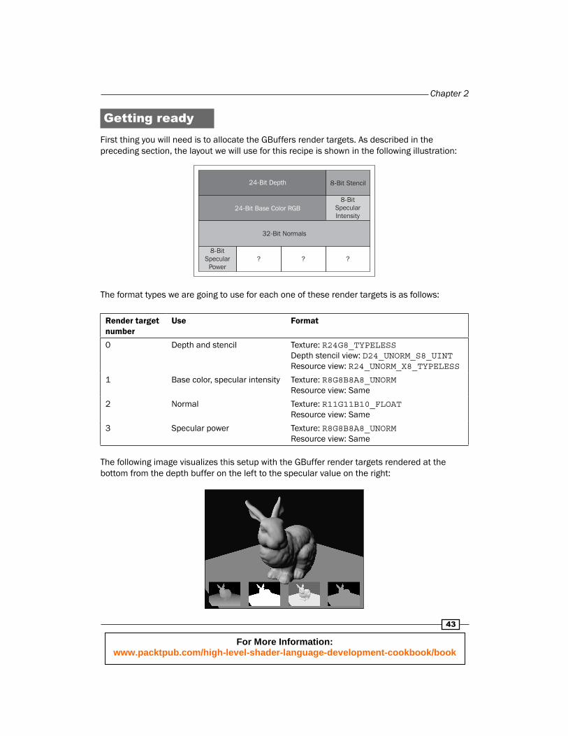
Getting readyFirst thing you will need is to allocate the GBuffers render targets. As described in the preceding section, the layout we will use for this recipe is shown in the following illustration:
24-Bit Depth 8-Bit Stencil
8-BitSpecularIntensity
24-Bit Base Color RGB
32-Bit Normals
8-BitSpecularPower
? ? ?
The format types we are going to use for each one of these render targets is as follows:
Render target number
Use Format
0 Depth and stencil Texture: R24G8_TYPELESSDepth stencil view: D24_UNORM_S8_UINTResource view: R24_UNORM_X8_TYPELESS
1 Base color, specular intensity Texture: R8G8B8A8_UNORMResource view: Same
2 Normal Texture: R11G11B10_FLOATResource view: Same
3 Specular power Texture: R8G8B8A8_UNORMResource view: Same
The following image visualizes this setup with the GBuffer render targets rendered at the bottom from the depth buffer on the left to the specular value on the right:
For More Information: www.packtpub.com/high-level-shader-language-development-cookbook/book
Deferred Shading
44
It is recommended by the GPU vendors to always allocate the GBuffer render targets fi rst and in sequence. That way the graphics cards driver assumes those targets are important and will be used together.
Unless you are using Multisample Anti-Aliasing MSAA, it's very likely that you would want your GBuffer textures to have the exact same size as your application / games back buffer. If that's the case, it is recommended that you save memory by using the back-buffer depth render target in your GBuffer instead of allocating a new one.
How to do it...Filling the GBuffer with data is pretty straightforward. Each frame you start by clearing the depth view with depth equal to 1 and the other targets to black as you would normally do. Then you need to set all four targets in the order presented by the diagram (see the Getting started… section). Once the targets are ready, it's time to render the opaque elements of the scene.
Unlike the shaders used for forward rendering, this time we are going to output three color values instead of one. This is done using the following shader output structure:
struct PS_GBUFFER_OUT{ float4ColorSpecInt : SV_TARGET0; float4 Normal : SV_TARGET1; float4SpecPow : SV_TARGET2;};
As you can see, this output structure outputs all the values we want to write into the GBuffer in the same order the GBuffer views are set for rendering. Note that the normal will be stored as a four component value instead of three. This is due to a compiler restriction that won't allow a pixel shader to output any other type of fl oating point value. Just fi ll the W component with something (it will be ignored when written into the target).
Normalizing the specular power is straightforward. Assuming the range is constant you can write the minimum value and the affective range (maximum - minimum) value into shader constants like this:
staticconst float2 g_SpecPowerRange = { 0.1, 250.0 };
For More Information: www.packtpub.com/high-level-shader-language-development-cookbook/book
Chapter 2
45
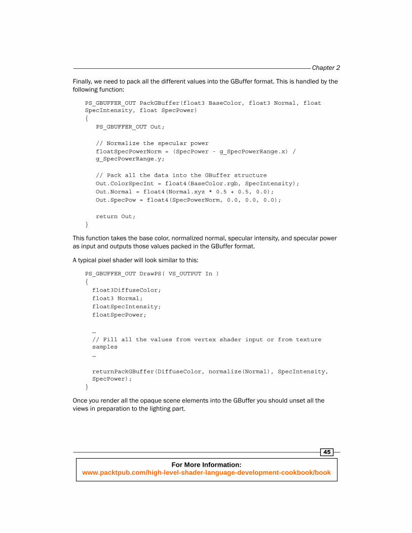
Finally, we need to pack all the different values into the GBuffer format. This is handled by the following function:
PS_GBUFFER_OUT PackGBuffer(float3 BaseColor, float3 Normal, float SpecIntensity, float SpecPower){ PS_GBUFFER_OUT Out;
// Normalize the specular power floatSpecPowerNorm = (SpecPower - g_SpecPowerRange.x) / g_SpecPowerRange.y;
// Pack all the data into the GBuffer structure Out.ColorSpecInt = float4(BaseColor.rgb, SpecIntensity); Out.Normal = float4(Normal.xyz * 0.5 + 0.5, 0.0); Out.SpecPow = float4(SpecPowerNorm, 0.0, 0.0, 0.0);
return Out;}
This function takes the base color, normalized normal, specular intensity, and specular power as input and outputs those values packed in the GBuffer format.
A typical pixel shader will look similar to this:
PS_GBUFFER_OUT DrawPS( VS_OUTPUT In ){ float3DiffuseColor; float3 Normal; floatSpecIntensity; floatSpecPower;
… // Fill all the values from vertex shader input or from texture samples …
returnPackGBuffer(DiffuseColor, normalize(Normal), SpecIntensity, SpecPower);}
Once you render all the opaque scene elements into the GBuffer you should unset all the views in preparation to the lighting part.
For More Information: www.packtpub.com/high-level-shader-language-development-cookbook/book
Deferred Shading
46
How it works...Most of the packing process should be self-explanatory. It is important to normalize the normal before passing it to the PackGBuffer function. Failing to do so can result in unneeded loss of precision.
Note that due to the specular power encoding, we no longer have to worry about zero or negative specular power. Once we unpack the GBuffer, a value of zero will be mapped to the minimum value we encoded with.
Depending on the specular power values and the range you plan on using, you may want to consider using a non-linear encoding. For example, you can store the square root of the normalized value and then square it while decoding in order to increase precision on the low end of the range.
There's more...It's a shame to leave the three components in the last render target unused. Among the things you can store in those components are:
Per-pixel X and Y velocity for motion blur
Ambient intensity mask
Directional shadow value
Material ID
GBuffer unpackingBefore any light related work can be accomplished, all the data stored in the GBuffer has to be unpacked back into a format that we can use with the lighting code presented in the forward lighting recipes.
You may have noticed one thing missing from our GBuffer and that is the world space position needed for lighting. Although we could store per-pixel world positions in our GBuffer, those positions are implicitly stored already in the depth buffer as non-linear depth. Together with the projection parameters, we are going to reconstruct the linear depth of each pixel (world distance from the camera) as part of the GBuffer unpacking process. The linear depth will later be used together with the inversed view matrix to reconstruct the world position of each pixel.
For More Information: www.packtpub.com/high-level-shader-language-development-cookbook/book

Chapter 2
47
Getting readyWhile unpacking the GBuffer, you always want to use point sampling when fetching data from the GBuffer texture views. You will need to set one point sampler and the four shader resource views for the pixel shader.
As mentioned in the introduction, we will also want to reconstruct the per-pixel linear depth. In addition to the depth buffer value, we will need some of the projection parameters used in the projection matrix to accomplish this task. Those additional projection values will be stored in a constant buffer that should be set for the pixel shader.
How to do it...In order to make use of the data in the GBuffer we will need to sample from it. For that we are going to defi ne the following textures:
Texture2D DepthTexture : register( t0 );Texture2D ColorSpecIntTexture: register( t1 );Texture2D NormalTexture: register( t2 );Texture2D SpecPowTexture: register( t3 );
You will need to set the shader resource views in the same order the texture register deceleration.
Once we unpack the GBuffer values, we are going to store them in a structure. This will make it easier to pass that data to the lighting functions. That structure is defi ned as follows:
struct SURFACE_DATA{ floatLinearDepth; float3 Color; float3 Normal; floatSpecInt; floatSpecPow;};
Next you will need to call the main unpacking function which looks like this:
SURFACE_DATA UnpackGBuffer(int2 location){ SURFACE_DATA Out;
// Cast to 3 component for the load function int3 location3 = int3(location, 0);
// Get the depth value and convert it to linear depth
For More Information: www.packtpub.com/high-level-shader-language-development-cookbook/book
Deferred Shading
48
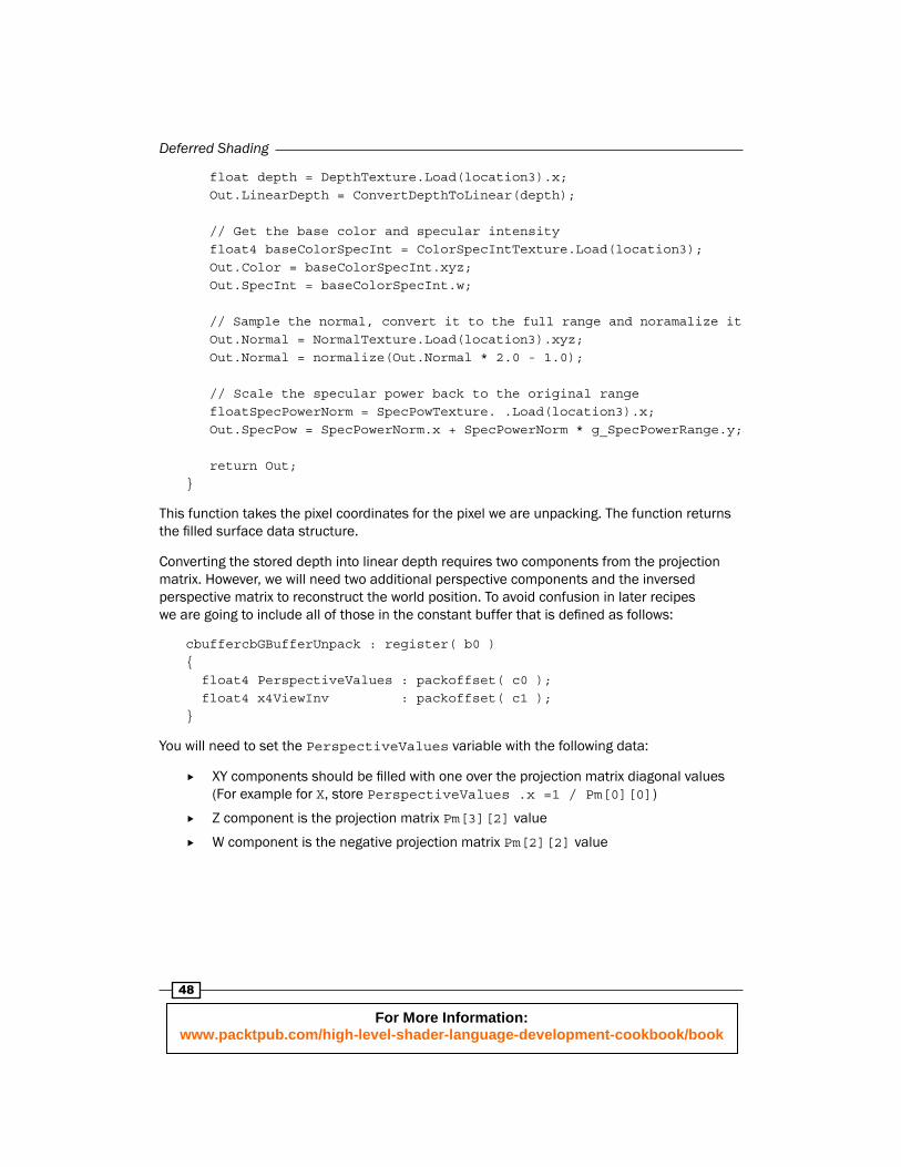
float depth = DepthTexture.Load(location3).x; Out.LinearDepth = ConvertDepthToLinear(depth);
// Get the base color and specular intensity float4 baseColorSpecInt = ColorSpecIntTexture.Load(location3); Out.Color = baseColorSpecInt.xyz; Out.SpecInt = baseColorSpecInt.w;
// Sample the normal, convert it to the full range and noramalize it Out.Normal = NormalTexture.Load(location3).xyz; Out.Normal = normalize(Out.Normal * 2.0 - 1.0);
// Scale the specular power back to the original range floatSpecPowerNorm = SpecPowTexture. .Load(location3).x; Out.SpecPow = SpecPowerNorm.x + SpecPowerNorm * g_SpecPowerRange.y;
return Out;}
This function takes the pixel coordinates for the pixel we are unpacking. The function returns the fi lled surface data structure.
Converting the stored depth into linear depth requires two components from the projection matrix. However, we will need two additional perspective components and the inversed perspective matrix to reconstruct the world position. To avoid confusion in later recipes we are going to include all of those in the constant buffer that is defi ned as follows:
cbuffercbGBufferUnpack : register( b0 ){ float4 PerspectiveValues : packoffset( c0 ); float4 x4ViewInv : packoffset( c1 );}
You will need to set the PerspectiveValues variable with the following data:
XY components should be fi lled with one over the projection matrix diagonal values (For example for X, store PerspectiveValues .x =1 / Pm[0][0])
Z component is the projection matrix Pm[3][2] value
W component is the negative projection matrix Pm[2][2] value
For More Information: www.packtpub.com/high-level-shader-language-development-cookbook/book
Chapter 2
49
The code to convert the sampled depth into linear depth is as follows:
float ConvertDepthToLinear(float depth){ float linearDepth = PerspectiveValues.z / (depth + PerspectiveValues.w); return linearDepth;}
This function takes the sampled depth as input and returns the linear depth.
How it works…As you may have expected, most of the code in the shader reads back the data from the GBuffer views. The specular power gets scaled back to its original range by using the inversed operation with the same values. The only part that requires further explanation is the conversion to linear depth.
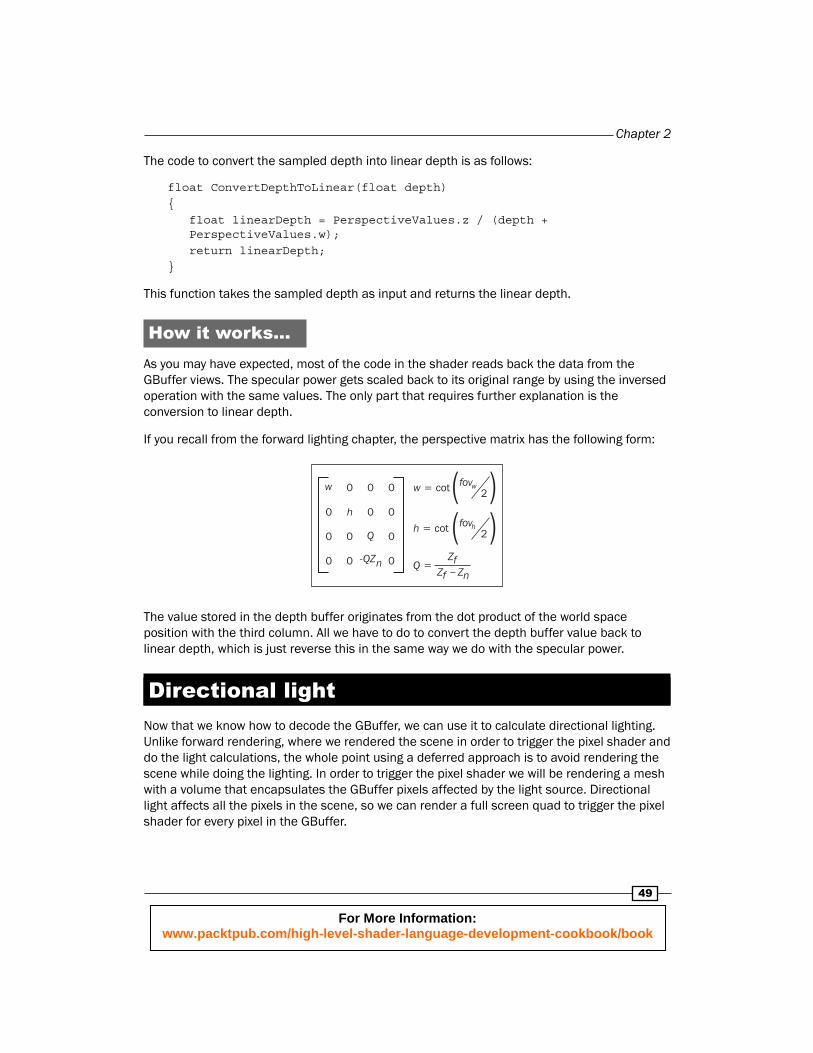
If you recall from the forward lighting chapter, the perspective matrix has the following form:
w
h
Q
-QZn
0 w = cot fovw2
h = cot fovh2
Q =Zf
Zf Zn-
0
0
0
00
00
00
00
The value stored in the depth buffer originates from the dot product of the world space position with the third column. All we have to do to convert the depth buffer value back to linear depth, which is just reverse this in the same way we do with the specular power.
Directional lightNow that we know how to decode the GBuffer, we can use it to calculate directional lighting. Unlike forward rendering, where we rendered the scene in order to trigger the pixel shader and do the light calculations, the whole point using a deferred approach is to avoid rendering the scene while doing the lighting. In order to trigger the pixel shader we will be rendering a mesh with a volume that encapsulates the GBuffer pixels affected by the light source. Directional light affects all the pixels in the scene, so we can render a full screen quad to trigger the pixel shader for every pixel in the GBuffer.
For More Information: www.packtpub.com/high-level-shader-language-development-cookbook/book
Deferred Shading
50
Getting ready…Back in the old days of Direct3D 9 you would need to prepare a vertex buffer to render a full screen quad. Fortunately, this is a thing of the past. With DirectX11 (as well as DirectX10) it is very easy to render a full screen quad with null buffers and sort out the values in the vertex shader. You will still need a constant buffer to store the same light information we used for the forward directional light.
In addition to the light information, we will need all the settings we used for unpacking the GBuffer including the shader resource view and the constant buffer. It is recommended you separate the GBuffer unpacking constants from the light related constants as the GBuffer constants are not going to change through the lighting stage.
One last thing you will have to take care of is to disable depth and nullify the depth buffer. The reason for doing so is that the full screen quad is not going to benefi t from depth testing as it is supposed to cover the whole visible area (there is also a restriction about sampling and writing to the same depth buffer, but we will discuss this in the next recipe).
How to do it...As with the forward directional light, we are going to use a buffer with the directional light information. You only need to set this buffer to the pixel shader. The buffer is defi ned as follows:
cbuffercbPerObject : register( b0 ){ float3 DirToLight : packoffset( c0 ); float4 DirLightColor : packoffset( c1 );}
We will be using the same material structure used for forward lighting that is defi ned as follows:
struct Material{ float3 normal; float4 diffuseColor; float specIntensity;};
In order to render a full screen quad, you will need to set both index and vertex buffers to null. Set the topology to triangle strip and call Draw with four vertices starting from position zero.
Our vertex shader output structure is defi ned as follows:
struct VS_OUTPUT{ float4 Position : SV_Position; float2 UV : TEXCOORD0;};
For More Information: www.packtpub.com/high-level-shader-language-development-cookbook/book
Chapter 2
51
We will be using a constant array in the vertex shader to help selecting the vertex clip-space positions for each vertex:
staticconst float2 arrBasePos[4] = { float2(-1.0, 1.0), float2(1.0, 1.0), float2(-1.0, -1.0), float2(1.0, -1.0),};
Finally, our vertex shader is defi ned as follows:
VS_OUTPUT DirLightVS(uintVertexID : SV_VertexID ){ VS_OUTPUT Output;
Output.Position = float4(arrPos[VertexID].xy, 0.0, 1.0); Output.cpPos = Output.Position.xy;
return Output;}
This function takes the vertex index (in our case a value between 0 and 6) and outputs the vertex projected position and clip-space XY positions.
Now that we sorted out the full-screen quad rendering, it's time to move on to the pixel shader code. Using all the helper functions presented during the GBuffer unpacking recipe plus the new function that reconstructs the world position, the work done by the shader is:
Unpack the GBuffer
Fill the material structure from the unpacked values
Reconstruct the world position
Calculate the ambient and directional light values
If you recall, we will be using the EyePosition function to fi nd the vector from the pixel to the camera, which is used for specular highlight calculation. Fortunately, this value is already present in the inversed view matrix. All we need to do in order to use it is to add this defi ne:
#define EyePositionViewInv[3].xyz;
The code that handles all the preceding steps is as follows:
float4 DirLightPS( VS_OUTPUT In ) : SV_TARGET{ // Unpack the GBuffer SURFACE_DATA gbd = UnpackGBuffer(In.Position, 0));
For More Information: www.packtpub.com/high-level-shader-language-development-cookbook/book
Deferred Shading
52
// Convert the data into the material structure Material mat; mat.normal = gbd.Normal; mat.diffuseColor.xyz = gbd.Color; mat.diffuseColor.w = 1.0; // Fully opaque mat.specPow = g_SpecPowerRange.x + g_SpecPowerRange.y * gbd.SpecPow; mat.specIntensity = gbd.SpecIntensity;
// Reconstruct the world position float3 position = CalcWorldPos(In.cpPos, gbd.LinearDepth);
// Calculate the ambient and directional light contributions float4 finalColor; finalColor.xyz = CalcAmbient(mat.normal, mat.diffuseColor.xyz); finalColor.xyz += CalcDirectional(position, mat); finalColor.w = 1.0; // Pixel is fully opaque
returnfinalColor;}
This function takes the output from the vertex shader, which includes the pixel texture position and clip space position, and returns the pixels shaded color.
Finally, the function that reconstructs the world position is as follows:
float3 CalcWorldPos(float2 csPos, float linearDepth){ float4 position;
position.xy = csPos.xy * PerspectiveValues.xy * linearDepth; position.z = linearDepth; position.w = 1.0;
return mul(position, ViewInv).xyz;}
This function takes the clip-space position and the linear depth as inputs and returns the original world position the depth value originated from.
For More Information: www.packtpub.com/high-level-shader-language-development-cookbook/book
Chapter 2
53
How it works…Rendering the full screen quad exploits the fact that you can now issue a draw call without using buffers. This option was added to DirectX10 as part as the new UAV (Unordered Access View) buffer. In a situation where all the required input data to a vertex shader is coming from a UAV, this new feature prevents the need to bind a vertex buffer even though you don't need it.
Reconstructing the world position is pretty straightforward. Once we have the linear depth, we manually construct the view space position by inverting the projection effect on the clip-space position. Then, using the inversed view matrix we can transform the view-space position back to world space.
Point lightCompared to the directional light, point lights may only cover parts of the screen. In addition, it may be partially or fully occluded by the scene as viewed when generating the GBuffer. Fortunately, all we need to represent the light source volume is to render the front of a sphere located at the point light's center position and scale to its range.
Representing the light source as its volume makes sense when you think about the portion of the scene encapsulated by this volume. In the point lights case, the portion of the scene that gets lit is going to be inside this sphere volume. Rendering the volume will trigger the pixel shader for all pixels that are inside the volume, but could also trigger the pixel shader for pixels that are in front or behind the volume. Those pixels that are outside the volume will either get culled by the depth test or get fully attenuated so they won't affect the fi nal image.
In the DirectX9 days you would normally use a pre-loaded mesh to represent the sphere. DirectX11 however, opens the possibility to render the volume by using the tessellation feature without any pre-loaded sphere mesh. After comparing the GPU performance cost for rendering the light volumes in both methods, I came to the conclusion that the HLSL generated volume is the right way to go.
Getting readySimilar to forward lighting, we want to accumulate the combined lit output of all the light sources. Once the directional (with ambient) light is rendered, we will be using additive alpha blending to accumulate the light values from all the other light types. You will need to set the blend state before rendering any point lights and keep using it until all the lights are rendered.
Rendering the point lights volume will require a different rasterizer and depth stencil states than what we have used before. While rendering the point light volume we will be culling front faces (normally, we cull back faces) and do a Greater Than Equals depth comparison test (usually, we do Less Than Equals). This will help us avoid culling some or all of the point light volume faces when the camera is inside the volume.
For More Information: www.packtpub.com/high-level-shader-language-development-cookbook/book
Deferred Shading
54
To create the new depth stencil state , use the following descriptor:
Depth stencil descriptor parameter ValueDepthEnable TRUE
DepthWriteMask D3D11_DEPTH_WRITE_MASK_ZERO
DepthFunc D3D11_COMPARISON_GREATER_EQUAL
The reset of the parameters should be set to zero.
To create the rasterizer state, use the following descriptor:
Rasterizer descriptor parameter ValueFillMode D3D11_FILL_SOLID
CullMode D3D11_CULL_BACK
The reset of the parameters should be set to zero.
We need to prepare a matrix that will transform the light volume from its local space to the projected space. To prepare that matrix, you will need to have the following information:
Light position
Light range
Camera view matrix
Camera projection matrix
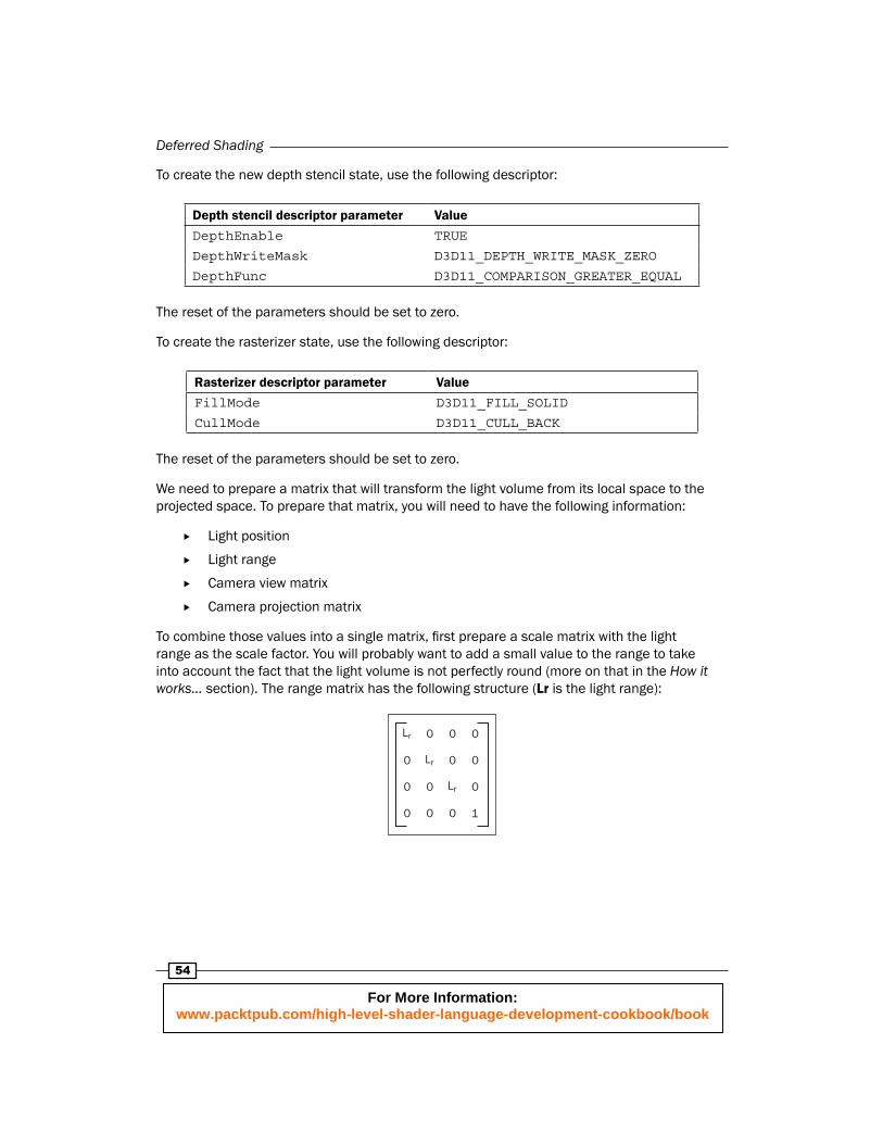
To combine those values into a single matrix, fi rst prepare a scale matrix with the light range as the scale factor. You will probably want to add a small value to the range to take into account the fact that the light volume is not perfectly round (more on that in the How it works… section). The range matrix has the following structure (Lr is the light range):
0
0
0
1
00
00
00
0 0
Lr
0
Lr
Lr
For More Information: www.packtpub.com/high-level-shader-language-development-cookbook/book
Chapter 2
55
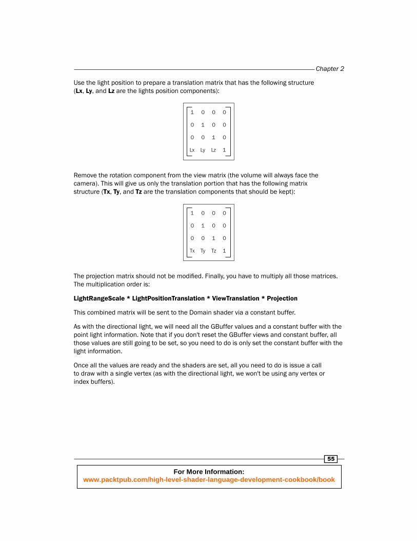
Use the light position to prepare a translation matrix that has the following structure (Lx, Ly, and Lz are the lights position components):
0
0
0
1
00
00
00
LyLx Lz
1
1
1
Remove the rotation component from the view matrix (the volume will always face the camera). This will give us only the translation portion that has the following matrix structure (Tx, Ty, and Tz are the translation components that should be kept):
0
0
0
1
00
00
00
TyTx Tz
1
1
1
The projection matrix should not be modifi ed. Finally, you have to multiply all those matrices. The multiplication order is:
LightRangeScale * LightPositionTranslation * ViewTranslation * Projection
This combined matrix will be sent to the Domain shader via a constant buffer.
As with the directional light, we will need all the GBuffer values and a constant buffer with the point light information. Note that if you don't reset the GBuffer views and constant buffer, all those values are still going to be set, so you need to do is only set the constant buffer with the light information.
Once all the values are ready and the shaders are set, all you need to do is issue a call to draw with a single vertex (as with the directional light, we won't be using any vertex or index buffers).
For More Information: www.packtpub.com/high-level-shader-language-development-cookbook/book
Deferred Shading
56
How to do it...Before we dive into the HLSL code we have to set a different primitive topology. As we will be using the tessellation feature we will be using the following topology: D3D11_PRIMITIVE_TOPOLOGY_1_CONTROL_POINT_PATCHLIST. In addition to the topology, set the depth stencil and rasterizer states we created in the Getting ready… section.
We will start with the light volume generation by calling Draw with 2 and 0 as inputs. Unlike all the previous recipes, we will be doing most of the heavy lifting in the Domain shader. The vertex shader code is as follows:
float4 PointLightVS() : SV_Position{ return float4(0.0, 0.0, 0.0, 1.0); }
This function takes no input and outputs a single position. We won't be using this position, but outputting a position is a minimum requirement for a vertex shader so we have to output something anyway.
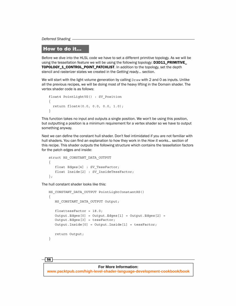
Next we can defi ne the constant hull shader. Don't feel intimidated if you are not familiar with hull shaders. You can fi nd an explanation to how they work in the How it works… section of this recipe. This shader outputs the following structure which contains the tessellation factors for the patch edges and inside:
struct HS_CONSTANT_DATA_OUTPUT{ float Edges[4] : SV_TessFactor; float Inside[2] : SV_InsideTessFactor;};
The hull constant shader looks like this:
HS_CONSTANT_DATA_OUTPUT PointLightConstantHS(){ HS_CONSTANT_DATA_OUTPUT Output; floattessFactor = 18.0; Output.Edges[0] = Output.Edges[1] = Output.Edges[2] = Output.Edges[3] = tessFactor; Output.Inside[0] = Output.Inside[1] = tessFactor;
return Output;}
For More Information: www.packtpub.com/high-level-shader-language-development-cookbook/book
Chapter 2
57
This function takes no input and outputs a structure with the tessellation values we want to apply to the patch. This implementation of the hull shader is very simple, so we won't be using any of the inputs. To simplify things we will be using a constant value that provides a decent amount of smoothness to the half sphere.
Similar to the vertex shader, our hull shader will need to output a position, only this time we will use it to switch between the two sides of the sphere. We will be using the following constant array to help us switch between the two sides:
static const float3 HemilDir[2] = { float3(1.0, 1.0,1.0), float3(-1.0, 1.0, -1.0)};
The code for the hull shader is as follows:
[domain("quad")][partitioning("integer")][outputtopology("triangle_ccw")][outputcontrolpoints(4)][patchconstantfunc("PointLightConstantHS")]float3 PointLightHS(uint PatchID : SV_PrimitiveID) : POSITION{ HS_OUTPUT Output;
Output.HemiDir = HemilDir[PatchID];
return Output;}
Basically, our hull shader will generate a patch with four control points that will get tessellated based on the value returned from the constant hull shader.
Once the tessellator is done, we will need a Domain shader to fi nd the fi nal position of each one of the generated quads. As always, the positions generated by the Domain shader have to be transformed into projected space. For that we will be using the matrix we built in the preceding section, which will be stored in the following constant buffer:
cbuffer cbPointLightDomain : register( b0 ){ float4x4 LightProjection : packoffset( c0 );}
For More Information: www.packtpub.com/high-level-shader-language-development-cookbook/book
Deferred Shading
58
We would also need a structure for the Domain shader return values which is defi ned as follows:
struct DS_OUTPUT{ float4 Position : SV_POSITION; float2 cpPos : TEXCOORD0;};
The Domain shader code is as follows:
[domain("quad")]DS_OUTPUT PointLightDS( HS_CONSTANT_DATA_OUTPUT input, float2 UV : SV_DomainLocation, constOutputPatch<HS_OUTPUT, 4> quad){ // Transform the UV's into clip-space float2 posClipSpace = UV.xy * 2.0 - 1.0;
// Find the absulate maximum distance from the center float2 posClipSpaceAbs = abs(posClipSpace.xy); float maxLen = max(posClipSpaceAbs.x, posClipSpaceAbs.y);
// Generate the final position in clip-space float3 normDir = normalize(float3(posClipSpace.xy, maxLen - 1.0) * quad[0].HemiDir); float4 posLS = float4(normDir.xyz, 1.0); // Transform all the way to projected space and generate the UV coordinates DS_OUTPUT Output; Output.Position = mul(posLS, LightProjection );
// Store the clip space position Output.cpPos = Output.Position.xy / Output.Position.w;
return Output;}
This function takes the UV coordinates generated by the tessellator as input and returns the projected and clip space positions of the vertex.
For More Information: www.packtpub.com/high-level-shader-language-development-cookbook/book
Chapter 2
59
So far we have covered all the code needed for generating the light volume and transforming it to projected space. Now it's time to do the light calculations in the pixel shader. As with the forward point light, we will need a constant buffer with the lights information:
cbuffercbPointLightPixel : register( b1 ){ float3 PointLightPos : packoffset( c0 ); float PointLightRange : packoffset( c0.w ); float3 PointColor : packoffset( c1 ); float PointIntensity : packoffset( c1.w );}
Finally, the code for the actual pixel shader:
float4PointLightPS( DS_OUTPUT In ) : SV_TARGET{ // Unpack the GBuffer SURFACE_DATA gbd = UnpackGBuffer(In.Position.xy); // Convert the data into the material structure Material mat; mat.normal = gbd.Normal; mat.diffuseColor.xyz = gbd.Color; mat.diffuseColor.w = 1.0; // Fully opaque mat.specPow = g_SpecPowerRange.x + g_SpecPowerRange.y * gbd.SpecPow; mat.specIntensity = gbd.SpecIntensity;
// Reconstruct the world position float3 position = CalcWorldPos(In.cpPos, gbd.LinearDepth);
// Calculate the light contribution float4 finalColor; finalColor.xyz = CalcPoint(position, mat); finalColor.w = 1.0;
return finalColor;}
This function takes the clip space position and texture coordinates as input and outputs the lit pixel value. As you can see, this is almost the exact copy of the directional light, the only thing that changed is the call to the CalcPoint function . The CalcPoint function is the exact copy of the function we used for forward lighting.
For More Information: www.packtpub.com/high-level-shader-language-development-cookbook/book
Deferred Shading
60
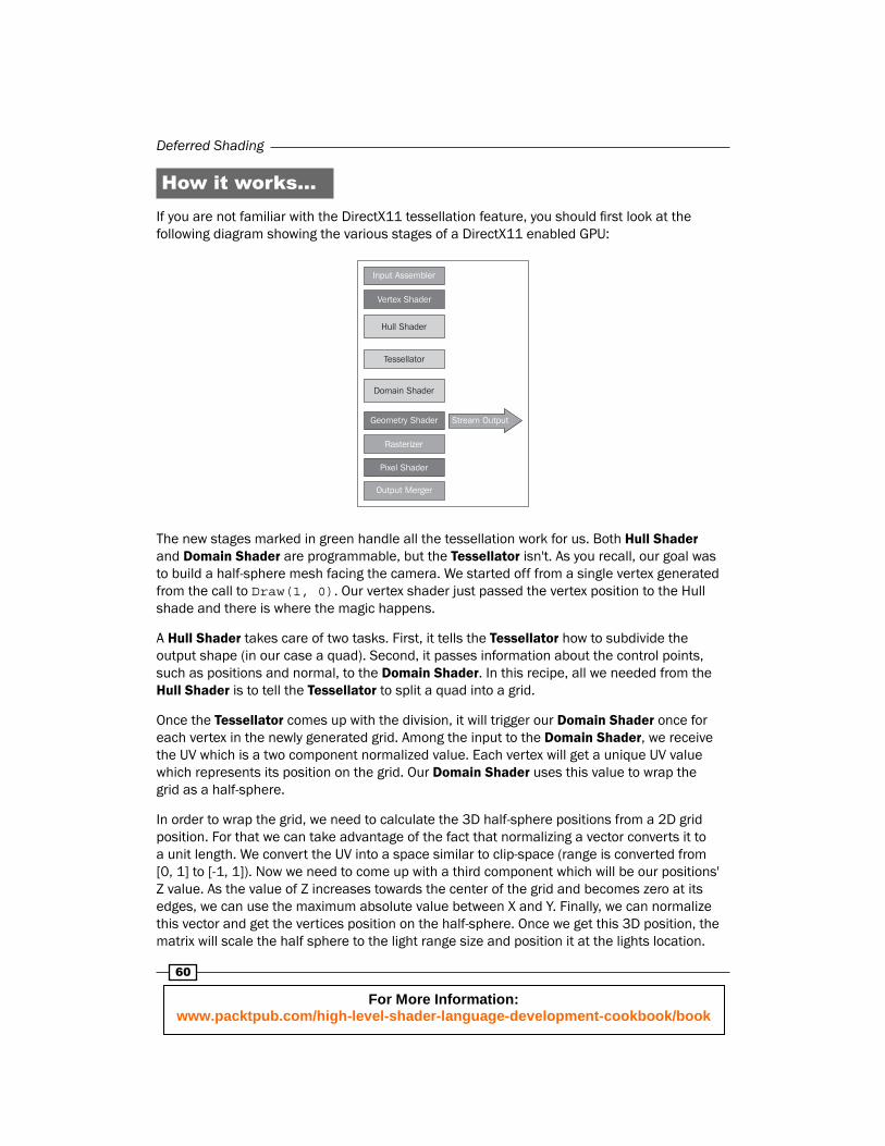
How it works…If you are not familiar with the DirectX11 tessellation feature, you should fi rst look at the following diagram showing the various stages of a DirectX11 enabled GPU:
Input Assembler
Vertex Shader
Hull Shader
Tessellator
Domain Shader
Geometry Shader
Rasterizer
Pixel Shader
Output Merger
Stream Output
The new stages marked in green handle all the tessellation work for us. Both Hull Shader and Domain Shader are programmable, but the Tessellator isn't. As you recall, our goal was to build a half-sphere mesh facing the camera. We started off from a single vertex generated from the call to Draw(1, 0). Our vertex shader just passed the vertex position to the Hull shade and there is where the magic happens.
A Hull Shader takes care of two tasks. First, it tells the Tessellator how to subdivide the output shape (in our case a quad). Second, it passes information about the control points, such as positions and normal, to the Domain Shader. In this recipe, all we needed from the Hull Shader is to tell the Tessellator to split a quad into a grid.
Once the Tessellator comes up with the division, it will trigger our Domain Shader once for each vertex in the newly generated grid. Among the input to the Domain Shader, we receive the UV which is a two component normalized value. Each vertex will get a unique UV value which represents its position on the grid. Our Domain Shader uses this value to wrap the grid as a half-sphere.
In order to wrap the grid, we need to calculate the 3D half-sphere positions from a 2D grid position. For that we can take advantage of the fact that normalizing a vector converts it to a unit length. We convert the UV into a space similar to clip-space (range is converted from [0, 1] to [-1, 1]). Now we need to come up with a third component which will be our positions' Z value. As the value of Z increases towards the center of the grid and becomes zero at its edges, we can use the maximum absolute value between X and Y. Finally, we can normalize this vector and get the vertices position on the half-sphere. Once we get this 3D position, the matrix will scale the half sphere to the light range size and position it at the lights lo cation.
For More Information: www.packtpub.com/high-level-shader-language-development-cookbook/book
Chapter 2
61
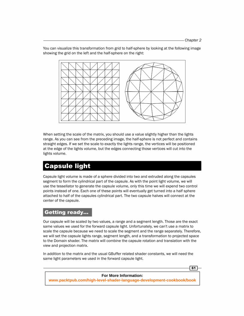
You can visualize this transformation from grid to half-sphere by looking at the following image showing the grid on the left and the half-sphere on the right:
When setting the scale of the matrix, you should use a value slightly higher than the lights range. As you can see from the preceding image, the half-sphere is not perfect and contains straight edges. If we set the scale to exactly the lights range, the vertices will be positioned at the edge of the lights volume, but the edges connecting those vertices will cut into the lights volume.
Capsule lightCapsule light volume is made of a sphere divided into two and extruded along the capsules segment to form the cylindrical part of the capsule. As with the point light volume, we will use the tessellator to generate the capsule volume, only this time we will expend two control points instead of one. Each one of these points will eventually get turned into a half sphere attached to half of the capsules cylindrical part. The two capsule halves will connect at the center of the capsule.
Getting ready…Our capsule will be scaled by two values, a range and a segment length. Those are the exact same values we used for the forward capsule light. Unfortunately, we can't use a matrix to scale the capsule because we need to scale the segment and the range separately. Therefore, we will set the capsule lights range, segment length, and a transformation to projected space to the Domain shader. The matrix will combine the capsule rotation and translation with the view and projection matrix.
In addition to the matrix and the usual GBuffer related shader constants, we will need the same light parameters we used in the forward capsule light.
For More Information: www.packtpub.com/high-level-shader-language-development-cookbook/book
Deferred Shading
62
How to do it...To start the rendering the capsule light, we will call Draw with two vertices from offset zero. This will invoke the vertex shader twice. As with the point and spot light, we don't care about the position the vertex shader will output, so we can use the same vertex shader we used for the other two light types.
In order to expend each vertex into a different half of the capsule, our Hull shader will need to output a different direction for each input control point. As we are forced to output a position, we will be using this output to specify the capsule direction. The new output structure for the Hull shader is as follows:
struct HS_OUTPUT{ float4 CapsuleDir : POSITION;};
We will store the two direction vectors in the following shader constant:
staticconst float4 CapsuelDir[2] = { float4(1.0, 1.0, 1.0, 1.0), float4(-1.0, 1.0, -1.0, 1.0)};
Out Hull shader will select the direction based on the primitive index, which is just the index of the vertex:
[domain("quad")][partitioning("integer")][outputtopology("triangle_ccw")][outputcontrolpoints(4)][patchconstantfunc("CapsuleLightConstantHS")]HS_OUTPUT CapsuleLightHS(uintPatchID : SV_PrimitiveID){ HS_OUTPUT Output;
Output.CapsuleDir = CapsuelDir[PatchID];
return Output;}
This function takes the primitive ID as input and outputs the capsule direction.
Our constant Hull shader is going to use a tessellation factor of 12 for both edges and inside values.
For More Information: www.packtpub.com/high-level-shader-language-development-cookbook/book
Chapter 2
63
We will be using three constants to split each quad into the half sphere and half cylinder portion in the Domain shader. We will be using 30 percent of the capsule length on the z axis for the half cylinder and the rest for the half sphere. Those constants with the Domain shader code look like this:
#define CylinderPortion 0.3#define SpherePortion (1.0 - CylinderPortion)#define ExpendAmount (1.0 + CylinderPortion)
Our Domain shader constant buffer that contains the capsule transformation to projected space along with half the length of the capsule segment and the range is defi ned as follows:
cbuffercbSpotLightDomain : register( b0 ){ float4x4 LightProjection : packoffset( c0 ); float HalfSegmentLen : packoffset( c4 ); float CapsuleRange : packoffset( c4.y );}
The Domain shader that uses these values to generate the capsule half:
[domain("quad")]DS_OUTPUT CapsuleLightDS( HS_CONSTANT_DATA_OUTPUT input, float2 UV : SV_DomainLocation, constOutputPatch<HS_OUTPUT, 4> quad){ // Transform the UV's into clip-space float2 posClipSpace = UV.xy * 2.0 - 1.0;
// Find the vertex offsets based on the UV float2 posClipSpaceAbs = abs(posClipSpace.xy); float maxLen = max(posClipSpaceAbs.x, posClipSpaceAbs.y); float2 posClipSpaceNoCylAbs = saturate(posClipSpaceAbs * ExpendAmount); float2 posClipSpaceNoCyl = sign(posClipSpace.xy) * posClipSpaceNoCylAbs; float maxLenNoCapsule = max(posClipSpaceNoCylAbs.x, posClipSpaceNoCylAbs.y);
// Generate the final position in clip-space float3 normDir = normalize(float3(posClipSpaceNoCyl.xy, maxLenNoCapsule - 1.0)) * CapsuleRange; float cylinderOffsetZ = saturate(maxLen - min(maxLenNoCapsule, SpherePortion)) / CylinderPortion; float4 posLS = float4(normDir.xy, normDir.z + cylinderOffsetZ * HalfSegmentLen- HalfSegmentLen, 1.0); // Move the vertex to the selected capsule side
For More Information: www.packtpub.com/high-level-shader-language-development-cookbook/book
Deferred Shading
64
posLS *= quad[0].CapsuleDir;
// Transform all the way to projected space and generate the UV coordinates DS_OUTPUT Output; Output.Position = mul(posLS, LightProjection ); Output.UV = Output.Position.xy / Output.Position.w; Output.UV = Output.UV * float2(0.5, -0.5) + 0.5;
return Output;}
This function takes the tessellator UV values and the capsule direction selected by the Hull shader as input and returns the projected capsule vertex with its matching UV coordinates.
As with the other deferred light types, we are going to use the same constant buffer and function to do the actual lighting calculation in the pixel shader. Our pixel shader looks similar to the other light types other than the call to CalcCapsule:
float4 CapsuleLightPS( DS_OUTPUT In ) : SV_TARGET{ // Unpack the GBuffer SURFACE_DATA gbd = UnpackGBuffer(In.UV); // Convert the data into the material structure Material mat; mat.normal = gbd.Normal; mat.diffuseColor.xyz = gbd.Color; mat.diffuseColor.w = 1.0; // Fully opaque mat.specPow = g_SpecPowerRange.x + g_SpecPowerRange.y * gbd.SpecPow; mat.specIntensity = gbd.SpecIntensity;
// Reconstruct the world position float2 cpPos = In.UV.xy * float2(2.0, -2.0) - float2(1.0, -1.0); float3 position = CalcWorldPos(cpPos, gbd.LinearDepth);
// Calculate the light contribution float4finalColor; finalColor.xyz = CalcCapsule(position, mat); finalColor.w = 1.0;
return finalColor;}
This function takes the Domain shader output and returns the lit pixel color.
For More Information: www.packtpub.com/high-level-shader-language-development-cookbook/book
Chapter 2
65
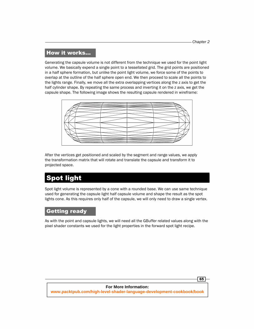
How it works…Generating the capsule volume is not different from the technique we used for the point light volume. We basically expend a single point to a tessellated grid. The grid points are positioned in a half sphere formation, but unlike the point light volume, we force some of the points to overlap at the outline of the half sphere open end. We then proceed to scale all the points to the lights range. Finally, we move all the extra overlapping vertices along the z axis to get the half cylinder shape. By repeating the same process and inverting it on the z axis, we get the capsule shape. The following image shows the resulting capsule rendered in wireframe:
After the vertices get positioned and scaled by the segment and range values, we apply the transformation matrix that will rotate and translate the capsule and transform it to projected space.
Spot lightSpot light volume is represented by a cone with a rounded base. We can use same technique used for generating the capsule light half capsule volume and shape the result as the spot lights cone. As this requires only half of the capsule, we will only need to draw a single vertex.
Getting readyAs with the point and capsule lights, we will need all the GBuffer related values along with the pixel shader constants we used for the light properties in the forward spot light recipe.
For More Information: www.packtpub.com/high-level-shader-language-development-cookbook/book
Deferred Shading
66
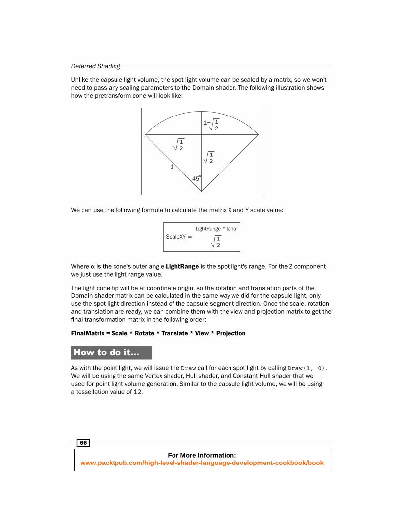
Unlike the capsule light volume, the spot light volume can be scaled by a matrix, so we won't need to pass any scaling parameters to the Domain shader. The following illustration shows how the pretransform cone will look like:
12
45
12
12
1
1
We can use the following formula to calculate the matrix X and Y scale value:
LightRange * tana
12
ScaleXY =
Where α is the cone's outer angle LightRange is the spot light's range. For the Z component we just use the light range value.
The light cone tip will be at coordinate origin, so the rotation and translation parts of the Domain shader matrix can be calculated in the same way we did for the capsule light, only use the spot light direction instead of the capsule segment direction. Once the scale, rotation and translation are ready, we can combine them with the view and projection matrix to get the fi nal transformation matrix in the following order:
FinalMatrix = Scale * Rotate * Translate * View * Projection
How to do it...As with the point light, we will issue the Draw call for each spot light by calling Draw(1, 0). We will be using the same Vertex shader, Hull shader, and Constant Hull shader that we used for point light volume generation. Similar to the capsule light volume, we will be using a tessellation value of 12.
For More Information: www.packtpub.com/high-level-shader-language-development-cookbook/book
Chapter 2
67
Our Domain shader will output the same output structure we used for both point and spot lights and will also use the capsule portion constant defi ned in the capsule light recipe. In addition, it will use the following two constant values:
#define CylinderPortion 0.2#define ExpendAmount (1.0 + CylinderPortion)
The code for the Domain shader is as follows:
[domain("quad")]DS_OUTPUT SpotLightDS( HS_CONSTANT_DATA_OUTPUT input, float2 UV : SV_DomainLocation, const OutputPatch<HS_OUTPUT, 4> quad){ // Transform the UV's into clip-space float2 posClipSpace = UV.xy * float2(2.0, -2.0) + float2(-1.0, 1.0);
// Find the vertex offsets based on the UV float2 posClipSpaceAbs = abs(posClipSpace.xy); float maxLen = max(posClipSpaceAbs.x, posClipSpaceAbs.y);
// Force the cone vertices to the mesh edge float2 posClipSpaceNoCylAbs = saturate(posClipSpaceAbs * ExpendAmount); float maxLenNoCapsule = max(posClipSpaceNoCylAbs.x, posClipSpaceNoCylAbs.y); float2 posClipSpaceNoCyl = sign(posClipSpace.xy) * posClipSpaceNoCylAbs;
// Convert the positions to half sphere with the cone vertices on the edge float3 halfSpherePos = normalize(float3(posClipSpaceNoCyl.xy, 1.0 - maxLenNoCapsule));
// Scale the sphere to the size of the cones rounded base halfSpherePos = normalize(float3(halfSpherePos.xy * SinAngle, CosAngle));
// Find the offsets for the cone vertices (0 for cone base) float cylinderOffsetZ = saturate((maxLen * ExpendAmount - 1.0) / CylinderPortion);
// Offset the cone vertices to their final position float4 posLS = float4(halfSpherePos.xy * (1.0 - cylinderOffsetZ), halfSpherePos.z - cylinderOffsetZ * CosAngle, 1.0);
// Transform all the way to projected space and generate the UV coordinates DS_OUTPUT Output;
For More Information: www.packtpub.com/high-level-shader-language-development-cookbook/book
Deferred Shading
68
Output.Position = mul( posLS, LightProjection ); Output.cpPos = Output.Position.xy / Output.Position.w;
return Output;}
This function takes the Hull shader outputs with the tessellator UV coordinates and returns the spot volume vertex position in projected space and the vertex UV coordinates.
For the pixel shader, we will be using the exact code we did for the point light, only this time we will be calling the CalcSpot function (instead of the call to the CalcPoint function). This will give us the following code:
float4 SpotLightPS( DS_OUTPUT In ) : SV_TARGET{ // Unpack the GBuffer float2 UV = In.UV; // This is not working so well... SURFACE_DATA gbd = UnpackGBuffer(UV); // Convert the data into the material structure Material mat; mat.normal = gbd.Normal; mat.diffuseColor.xyz = gbd.Color; mat.diffuseColor.w = 1.0; // Fully opaque mat.specPow = g_SpecPowerRange.x + g_SpecPowerRange.y * gbd.SpecPow; mat.specIntensity = gbd.SpecIntensity;
// Reconstruct the world position float2 cpPos = UV.xy * float2(2.0, -2.0) - float2(1.0, -1.0); float3 position = CalcWorldPos(cpPos, gbd.LinearDepth);
// Calculate the light contribution float4 finalColor; finalColor.xyz = CalcSpot(position, mat); finalColor.w = 1.0;
return finalColor;}
This function takes the Domain shader output and returns the light pixel color.
For More Information: www.packtpub.com/high-level-shader-language-development-cookbook/book
Chapter 2
69
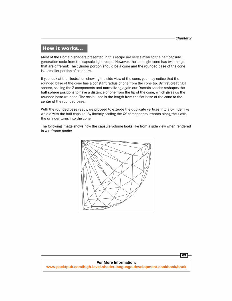
How it works…Most of the Domain shaders presented in this recipe are very similar to the half capsule generation code from the capsule light recipe. However, the spot light cone has two things that are different: The cylinder portion should be a cone and the rounded base of the cone is a smaller portion of a sphere.
If you look at the illustration showing the side view of the cone, you may notice that the rounded base of the cone has a constant radius of one from the cone tip. By fi rst creating a sphere, scaling the Z components and normalizing again our Domain shader reshapes the half sphere positions to have a distance of one from the tip of the cone, which gives us the rounded base we need. The scale used is the length from the fl at base of the cone to the center of the rounded base.
With the rounded base ready, we proceed to extrude the duplicate vertices into a cylinder like we did with the half capsule. By linearly scaling the XY components inwards along the z axis, the cylinder turns into the cone.
The following image shows how the capsule volume looks like from a side view when rendered in wireframe mode:
For More Information: www.packtpub.com/high-level-shader-language-development-cookbook/book
Where to buy this book You can buy HLSL Development Cookbook from the Packt Publishing website: http://www.packtpub.com/high-level-shader-language-development-cookbook/book. Free shipping to the US, UK, Europe and selected Asian countries. For more information, please read our shipping policy.
Alternatively, you can buy the book from Amazon, BN.com, Computer Manuals and most internet book retailers.
www.PacktPub.com
For More Information: www.packtpub.com/high-level-shader-language-development-cookbook/book