Embed Size (px)
Citation preview

Improper installation, adjustment, alteration, service or maintenance can cause property damage, injury or death. Read the installation, operation and maintenance instructions thoroughly before installing or servicing this equipment.
This heater must be installed and serviced by trained gas installation and service personnel only. Failure to comply could result in personal injury, asphyxiation, death, fire or property damage.
In locations used for the storage of combustible materials, signs must be posted to specify the maximum permissible stacking height to maintain the required clearances from the heater to the combustibles. Signs must either be posted adjacent to the heater thermostats or in the absence of such thermostats, in a conspicuous location.
Not for residential use! Do not use this heater in the home, sleeping quarters, attached garages, etc. Installation of a commercial tube heater system in residential indoor spaces may result in property damage, serious injury, asphyxiation or death.
WARNING!
HLV Series Tube HeaterVacuum System
For Your Safety
If you smell gas:
• Do not try to light any appliance. • Immediately call your gas supplier from a neighbor’s phone.• Do not touch any electrical switch. • Follow the gas supplier’s instructions. • Do not use any phone in your building. • If you cannot reach your gas supplier, call the fire department. Keep these instructions for future reference.
The HLV Series Infrared Tube Heater is a negative pressure, two stage radiant heater vacuum system designed to provide comfort heat. Consisting of four main components; a burner control box, radiant tubes, reflector assembly and vacuum exhauster, this system generates infrared energy to heat the objects in the space. These objects then reradiate this heat, creating a comfort zone at the floor level. This is how large spaces can be heated efficiently without having to provide primary infrared for every square foot of space.
Design, Installation, Operation and Maintenance Manual
LIOHLV-Rev. 21711Print: 2M-8/13_r5-12/15(CDS)
Replaces: LIOHLV-2M-3/15(CDS)

2
HLV Series
Contents
1.0 Introduction . . . . . . . . . . . . . . . . . . . . . . . . . . . . . . . . . . . . . . . . . . . . . . . . . . . . . . . . . . . . . . . . . . . . 3 HLV Series Specifications . . . . . . . . . . . . . . . . . . . . . . . . . . . . . . . . . . . . . . . . . . . . . . . . . . . . 4 Approvals Standards and Certifications . . . . . . . . . . . . . . . . . . . . . . . . . . . . . . . . . . . . . . . . . 5 Safety Labels and Locations . . . . . . . . . . . . . . . . . . . . . . . . . . . . . . . . . . . . . . . . . . . . . . . . . . 6 Clearance to Combustibles . . . . . . . . . . . . . . . . . . . . . . . . . . . . . . . . . . . . . . . . . . . . . . . . . . . 8
2.0 Design . . . . . . . . . . . . . . . . . . . . . . . . . . . . . . . . . . . . . . . . . . . . . . . . . . . . . . . . . . . . . . . . . . . . . . . 10 Pre-Design. . . . . . . . . . . . . . . . . . . . . . . . . . . . . . . . . . . . . . . . . . . . . . . . . . . . . . . . . . . . . . . 10 Design for Non-Condensing Systems. . . . . . . . . . . . . . . . . . . . . . . . . . . . . . . . . . . . . . . . . . 11 Design for Condensing Systems . . . . . . . . . . . . . . . . . . . . . . . . . . . . . . . . . . . . . . . . . . . . . . 12 System Design Definitions. . . . . . . . . . . . . . . . . . . . . . . . . . . . . . . . . . . . . . . . . . . . . . . . . . . 14 Typical System Layouts . . . . . . . . . . . . . . . . . . . . . . . . . . . . . . . . . . . . . . . . . . . . . . . . . . . . . 15 Vacuum Pump Application . . . . . . . . . . . . . . . . . . . . . . . . . . . . . . . . . . . . . . . . . . . . . . . . . . 18 Damper Application . . . . . . . . . . . . . . . . . . . . . . . . . . . . . . . . . . . . . . . . . . . . . . . . . . . . . . . . 19
3.0 Installation . . . . . . . . . . . . . . . . . . . . . . . . . . . . . . . . . . . . . . . . . . . . . . . . . . . . . . . . . . . . . . . . . . . . 20 Pre-Installation. . . . . . . . . . . . . . . . . . . . . . . . . . . . . . . . . . . . . . . . . . . . . . . . . . . . . . . . . . . . 20 Vacuum Pump Assembly and Mounting . . . . . . . . . . . . . . . . . . . . . . . . . . . . . . . . . . . . . . . . 21 Tube Assembly and Mounting . . . . . . . . . . . . . . . . . . . . . . . . . . . . . . . . . . . . . . . . . . . . . . . . 23 Elbows and Intersections. . . . . . . . . . . . . . . . . . . . . . . . . . . . . . . . . . . . . . . . . . . . . . . . . . . . 25 Baffle Assembly and Placement . . . . . . . . . . . . . . . . . . . . . . . . . . . . . . . . . . . . . . . . . . . . . . 27 Reflector Assembly . . . . . . . . . . . . . . . . . . . . . . . . . . . . . . . . . . . . . . . . . . . . . . . . . . . . . . . . 28 Burner Assembly and Mounting . . . . . . . . . . . . . . . . . . . . . . . . . . . . . . . . . . . . . . . . . . . . . . 30 Flue Venting. . . . . . . . . . . . . . . . . . . . . . . . . . . . . . . . . . . . . . . . . . . . . . . . . . . . . . . . . . . . . . 31 Combustion Air Requirements . . . . . . . . . . . . . . . . . . . . . . . . . . . . . . . . . . . . . . . . . . . . . . . 33 Electrical Requirements. . . . . . . . . . . . . . . . . . . . . . . . . . . . . . . . . . . . . . . . . . . . . . . . . . . . . 34 Gas Supply . . . . . . . . . . . . . . . . . . . . . . . . . . . . . . . . . . . . . . . . . . . . . . . . . . . . . . . . . . . . . . 39
4.0 Operation . . . . . . . . . . . . . . . . . . . . . . . . . . . . . . . . . . . . . . . . . . . . . . . . . . . . . . . . . . . . . . . . . . . . . 42 Lighting and Shutdown . . . . . . . . . . . . . . . . . . . . . . . . . . . . . . . . . . . . . . . . . . . . . . . . . . . . . 42 Sequence of Operation . . . . . . . . . . . . . . . . . . . . . . . . . . . . . . . . . . . . . . . . . . . . . . . . . . . . . 42 Thermostat. . . . . . . . . . . . . . . . . . . . . . . . . . . . . . . . . . . . . . . . . . . . . . . . . . . . . . . . . . . . . . . 43 Diagnostics . . . . . . . . . . . . . . . . . . . . . . . . . . . . . . . . . . . . . . . . . . . . . . . . . . . . . . . . . . . . . . 43 System Start-Up Pre-Checks . . . . . . . . . . . . . . . . . . . . . . . . . . . . . . . . . . . . . . . . . . . . . . . . 44 Damper Adjustment. . . . . . . . . . . . . . . . . . . . . . . . . . . . . . . . . . . . . . . . . . . . . . . . . . . . . . . . 44
5.0 Maintenance . . . . . . . . . . . . . . . . . . . . . . . . . . . . . . . . . . . . . . . . . . . . . . . . . . . . . . . . . . . . . . . . . . . 45 Routine Inspection. . . . . . . . . . . . . . . . . . . . . . . . . . . . . . . . . . . . . . . . . . . . . . . . . . . . . . . . . 45 Troubleshooting Guide. . . . . . . . . . . . . . . . . . . . . . . . . . . . . . . . . . . . . . . . . . . . . . . . . . . . . . 46 Replacement Parts . . . . . . . . . . . . . . . . . . . . . . . . . . . . . . . . . . . . . . . . . . . . . . . . . . . . . . . . 50 6.0 Limited Warranty . . . . . . . . . . . . . . . . . . . . . . . . . . . . . . . . . . . . . . . . . . . . . . . . . . . . . . . . . . . . . . . 52
Table of Contents

Overview
The intent of this manual is to provide information regarding general safety, installation, operation and maintenance of the tube heater vacuum system. You must read, and understand, the instructions and safety warnings in this manual before installing the heating system.
System Components*
Prior to installation, verify that the heater’s gas type and voltage (as listed on the rating plate) match that of your application. Also verify that you have received all heater contents included with your system by checking them against the packing list. Materials not included in the heater kit contents (e.g., screws, vent material, terminals, etc.) are the responsibility of the installer. Notify your product representative or Detroit Radiant Products of any discrepancy or missing kit contents prior to installing unit.
1.0 Introduction
Figure 1.1 • Typical System Components*
* Each HLV Series vacuum system is engineered specific to each application’s design parameters. Some items illustrated may not be required with your system.
Tube Hanger
Standard Reflector
Reflector Center Support
Primary/Secondary Combustion Chamber(s)
Baffles
Reflector End Cap w/Clips
Tube Clamp
Burner Control Box
SS Flex Connector
Shut-off Valve
Radiant Tube(s)
Ignitor/Sensor Box
Chain Set
16” Burner Tube
Reflector Tension Spring
Isolation Boot
Turnbuckle.
Vacuum Pump
Damper
3
HLV Series 1.0 Introduction • Overview • System Components
Refer to pages 50-51 for a complete parts breakdown.

4
HLV Series1.0 Introduction • HLV Series Specifications
Burner Model
Gas Types
BTU/H (High Fire)
BTU/H (Low Fire)
Approximate System Hanging Weights
Typical Mounting Height^
Combustion Chamber
(Black Coated)
Radiant Emitter
Tube(s)** Condensing
Pipe
Per Burner Head
Per 10 Ft. Radiant Pipe & Reflector
Section
Per 10 Ft. Tailpipe & Reflector Section
HLV-40* N or P 40,000 40,000 35 lbs. 35 lbs. 45 lbs. 9’ to 14’ Al-TiCoated Alum or Uncoated HRT
304 Stainless Steel
HLV-50* N or P 50,000 50,000 35 lbs. 35 lbs. 45 lbs. 9’ to 14’ Al-TiCoated Alum or Uncoated HRT
304 Stainless Steel
HLV-60 N or P 60,000 50,000 35 lbs. 35 lbs. 45 lbs. 10’ to 15’ Al-TiCoated Alum or Uncoated HRT
304 Stainless Steel
HLV-75 N or P 75,000 60,000 35 lbs. 35 lbs. 45 lbs. 11’ to 18’ Al-TiCoated Alum or Uncoated HRT
304 Stainless Steel
HLV-80 N or P 80,000 64,000 35 lbs. 35 lbs. 45 lbs. 11’ to 18’ Al-TiCoated Alum or Uncoated HRT
304 Stainless Steel
HLV-90 N or P 90,000 72,000 35 lbs. 35 lbs. 45 lbs. 12’ to 20’ Al-TiCoated Alum or Uncoated HRT
304 Stainless Steel
HLV-100 N or P 100,000 80,000 35 lbs. 35 lbs. 45 lbs. 12’ to 20’ Al-TiCoated Alum or Uncoated HRT
304 Stainless Steel
HLV-110 N or P 110,000 88,000 35 lbs. 35 lbs. 45 lbs. 13’ to 23’ Al-TiCoated Alum or Uncoated HRT
304 Stainless Steel
HLV-120 N or LP 120,000 96,000 35 lbs. 35 lbs. 45 lbs. 13’ to 25’ Al-TiCoated Alum or Uncoated HRT
304 Stainless Steel
HLV-125 N or P 125,000 100,000 35 lbs. 35 lbs. 45 lbs. 14’ to 27’ Al-TiCoated Alum or Uncoated HRT
304 Stainless Steel
HLV-140 N or P 140,000 112,000 35 lbs. 35 lbs. 45 lbs. 15’ to 30’ Al-TiCoated Alum or Uncoated HRT
304 Stainless Steel
HLV-150 N or P 150,000 120,000 35 lbs. 35 lbs. 45 lbs. 15’ to 30’ Al-TiCoated Alum or Uncoated HRT**
304 Stainless Steel
HLV-170 N or P 170,000 136,000 35 lbs. 35 lbs. 45 lbs. 16’ to 40’ Al-TiCoated Alum or Uncoated HRT**
304 Stainless Steel
HLV-175 N or P 175,000 140,000 35 lbs. 35 lbs. 45 lbs. 17’ to 42’ Al-TiCoated Alum or Uncoated HRT**
304 Stainless Steel
HLV-180 N or P 180,000 144,000 35 lbs. 35 lbs. 45 lbs. 18’ to 47’ Al-TiCoated Alum or Uncoated HRT**
304 Stainless Steel
HLV-200 N or P 200,000 160,000 35 lbs. 35 lbs. 45 lbs. 19’ to 50’ Al-TiCoated Alum or Uncoated HRT**
304 Stainless Steel
Specifications
Chart 1.1 • HLV Series Specifications
* The HLV-40 and HLV-50 do not have a reduction for low fire.** All systems are designed to utilize either black coated aluminized steel (Alum) or uncoated hot-rolled steel (HRT)
radiant emitter tubes. On systems designed with the hot-rolled steel option, a coated aluminized steel radiant tube (TP-26A) must be installed immediately downstream of the titanium stabilized aluminized steel (Al-Ti) combustion chamber (TP-26B) on burner models HLV-150, 170, 175, 180 and 200 only.
^ Recommended mounting heights are provided as a guideline. Actual conditions may dictate variations from this data.NOTE: Burner models HLV-170, 175, 180 and 200 receive TP-220 stainless steel tube clamp.

5
HLV Series 1.0 Introduction • Approval Standards and Certifications • Applications
Applications
WARNING!
This is not an explosion proof heater. No tube heater may be used in a Class 1 or Class 2 Explosive Environment. Consult your local Fire Marshall, insurance carrier and other authorities for approval if the proposed installation is in question.
Commercial/Industrial: Unless otherwise indicated, tube heaters are designed and certified for use in industrial and commercial buildings, such as warehouses, manufacturing plants, aircraft hangars and vehicle maintenance shops. For maximum safety the building must be evaluated for potential problems before installing the heating system. A critical safety factor to consider before installation is the clearanceto combustibles (see pgs. 8-9).
Not For Residential Use. Installation of a commercial tube heater system in residential indoor spaces may result in property damage, serious injury or death.
Public Garages: Installation of this tube heater in public garages must conform with the Standard forParking Structures NFPA 88A (latest edition) or the Code for Motor Fuel Dispensing Facilities and RepairGarages NFPA 30A (latest edition).
• Heaters must not be installed less than 8 ft. (2.4m) above the floor. Minimum clearances to combustibles must be maintained from vehicles parked below the heater.
• When installed over hoists, minimum clearances to combustibles must be maintained from the upper most point of objects on the hoist.
Aircraft Hangars: Installation of this tube heater in aircraft hangars must conform with the Standard forAircraft Hangars, ANSI/NFPA 409 (latest edition).
• In areas adjoining the aircraft storage area (e.g., shops, offices) the bottom of heaters shall be installed no less than 8 ft. (2.4m) above the floor.
• Suspended or elevated heaters shall be located in spaces where they shall not be subject to damage by aircraft, cranes, movable scaffolding or other objects.
High Altitude: Installation of this tube heater is approved, without modifications, for elevations up to 6,000 feet (1,829m) MSL (sea level) in the United States. Contact the factory for installations above these elevations.
Approval Standards and Certifications
Installation of this tube heater must comply with all applicable local, state and national specifications, regulations and building codes. Contact the local building inspector and/or fire Marshall for guidance.
In the absence of local codes, the installation must conform to the latest edition of:
United States: National Fuel Gas Code, ANSI Z223.1 (NFPA 54).
Canada: CAN/CGA B149.1 and .2, Canadian Electrical Code C22.1.
• ANSI Z83.20b - American National Standards Institute. • OSHA - Occupational Safety & Health Administration.
• CSA - Canadian Standards Association. • Indoor approval.

Safety Labels and Their Locations
Read and understand all safety information and warnings in this manual before installation, operation and maintenance of the radiant tube heater system.
Top Panel
Bottom Panel
F/N: LLTCL012 Clearance to Combustibles Label.
F/N: LLLOGO1
Burner Control Box Component Label (located under the top panel)
Safety warning labels must be maintained on the heating system. Safety labels and their locations are illustrated below and on page 7. Product safety signs or labels should be replaced by the product user when they no longer are legible.
It is important to provide warnings to alert individuals to potential hazards and safety actions. ANSI Z83.20b and CSA 2.34 requires you to post a sign near the heater’s thermostat, or in absence of such thermostat, in a conspicuous location “specifying the maximum permissible stacking height to maintain the required clearances from the heater to combustibles.” A Clearance Safety Limit Tag (F/N: LL01) is provided with each burner control box (see p.7). Contact Detroit Radiant Products Company or an authorized distributor for obtaining safety signs or replacement labels and tags.
HLV-40-125N
Data on this label is for the model shown on this label. If your heater has been converted, this information is not accurate. Please contact the factory for assistance.
BURNER COMPONENTS:
For parts replacement information, contact factory at 586-756-0950 or visit www.drp-co.com/parts.
Serial No.: 0807XXXXXXXXXX 0001
Gas Valve:Circuit Board:Wire Harness:N.O. Switch:N.O. VL Orifice:N.C. Switch:N.C. VL Orifice:Diff Switch:Diff VL Orifice:Igniter:Burner:16” Tube:Ind. Lights:
Diag. Light:Term. Block:Transformer:Fan:Alt. Fan:Alt. Fan Usage:Relay:Filter:24 Volt In:120 Volt In:Gas In:Extra VL Orifice:
Production Code: Version:
Stock: Add-On:
Internal Use Only:HEATER TYPE: Electric:
Tag:Special 1:Special 2:
Gas:Air:C1
C1 C2 C3
None
N/A
HLV-125
5.05
36G54-224-N6465H3 PCS HarnessNoneNoneNoneNoneIS22016051F5169Grey (+ / -)NortonHigh4” Stnd.Yellow - 24V
(Specify TP-#’s)
1540A12513-PCS HarnessN/A
N/A
264E
50201B380828
Red LEDNone40 VAFasco Lg.50Hz - 120VWhen SpecifiedPicker x2None3 T-plug2x4 Box7/8” FCNone
827N/A82655A55B
1527N/A8326683
3 1 1/2”
TP-204#TP-44#
31 5/8”
LLWT038None
11 5/8”
171 7/16”
Orifice Type:
SAMPLE
6
HLV Series1.0 Introduction • Safety Labels and Locations

F/N: LLV3EP2Orange Crescent
®
DETROIT RADIANT PRODUCTS COMPANY21400 HOOVER ROAD - WARREN, MI
RE-VERBER-RAY INFRA-RED RADIANT TUBE HEATERFOR OUTDOOR USE AND INDOOR (Non-Residential) INSTALLATION ONLY.Class IIIA Permanent Label
(586) 756-0950 - www.drp-co.com
Volts AC:
AMPS - Starting:
AMPS - Running:
Combustion Chamber:
120V - 60Hz
4.8
1.1
4” Black Coated Aluminized For stainless steel upgrades: The combustion tube is 409 Series stainless steel.
DESIGN COMPLIES WITH:ANSI Z83.20b-2004-GAS FIRED LOW INTENSITY INFRA-RED HTR.
Manifold Pressure:
Maximum Inlet Pressure:
Minimum Inlet Pressure:
3.5 in.
14 in.
5.0 in.
W.C.P.
W.C.P.
W.C.P.
Serial No.: 0807XXXXXXXXXX 0001
MODEL NO.
HLV-40-125N
Heater Type
Minimum Mounting Angle:
Maximum Mounting Angle:
C1
0
45
DEGREES
DEGREES
INPUT BTU/H
125,000 / 95,000FOR USE WITH
Natural Gas
SAMPLE
7
HLV Series
SERVICE ACCESS PANELIGNITER & FLAME SENSE COMPARTMENT
1. Turn off gas & electricity.2. Remove cover by lifting top cover upward and outward.
CAUTION: HOT SURFACE.KEEP COVER IN PLACE. REMOVE FOR SERVICE ONLY.
SERVICE ACCESS PANELIGNITER & FLAME SENSE COMPARTMENT
1. Turn off gas & electricity.2. Remove cover by lifting top cover upward and outward.
CAUTION: HOT SURFACE.KEEP COVER IN PLACE. REMOVE FOR SERVICE ONLY.
F/N: LLTB026
Right Panel (Valve Compartment)
RadiantTube
Combustion Chamber16” Burner Tube
Left Panel (Controls Compartment)
AVOID EQUIPMENT FAILURE
THIS 10 FT. TUBE IS THE COMBUSTION CHAMBER.
THIS TUBE MUST BE THE FIRST TUBE FOLLOWING THE BURNER CONTROL BOX.
! INSTALLER
The combustion chamber utilizes either 409 stainless, titanium alloy or aluminized steel -
depending on the model number of your heater.
Rotate the tube’s welded seam to bottom. Consult the manual(s) for further details.
F/N: LLTB004 (orange)
F/N: LL01 - Clearance Safety Limit Tag (Affix adjacent to heater’s thermostat)
F/N: LLV2EP9
1.0 Introduction • Safety Labels and Locations
NEUTRAL
EARTH
HOT
- 120V HEATER INPUT -
120V
Back Panel
Rating Plate
F/N: LLTB018 (Natural Gas)F/N: LLTB019 (LP Gas)
NEUTRAL
EARTH
HOT
- 120V HEATER INPUT -
120V
F/N: LLV3EP1
Air Metering OrificeDO NOT REMOVE
TP-114TP-3014
3” F/N: LLAC Air Metering Orifice
SAMPLE
F/N: LLV2EP15

WARNING!
Placement of explosive objects, flammable objects, liquids and vapors close to the heater may result in explosion, fire, property damage, serious injury or death. Do not store or use explosive objects, liquids or vapor in the vicinity of the heater.
Clearance to combustibles is defined as the minimum distance that must exist between the tube surface, or reflector, and any combustible items (see Figure 1.2). It also pertains to the distance that must be maintained from moving objects around the tube heater. Moving items include, but are not limited to, vehicle lifts, overhead doors, cranes and hoists. For instance, if vehicle lifts are present, ensure that clearances will be maintained from the highest raised vehicle.
If you are unsure of the potential hazards in the application, consult your local fire Marshall, fire insurance carrier or other qualified authorities on the installation and approval of the proposed installation.
Clearance to Combustibles
Clearances listed in Chart 1.2 apply to each individual burner in the HLV system. When installing the tube heater vacuum system, clearances to combustibles for each burner model and its applicable tube run must be maintained. Inspect each burner rating label to ensure that clearances are maintained.
In locations used for the storage of combustible materials, signs must be posted to specify the maximum permissible stacking height to maintain the required clearances from the heater to combustibles. Signs must be posted adjacent to the heater’s thermostats or, in the absence of such thermostats, in a conspicuous location.
The stated clearance to combustibles represents a surface temperature of 90°F (50°C) above room temperature. Building materials with a low heat tolerance (such as plastics, vinyl siding, canvas, tri-ply, etc.) may be subject to degradation at lower temperatures. It is the installer’s responsibility to assure that adjacent materials are protected from degradation.
8
HLV Series
Failure to maintain minimum clearance to combustibles may result in fire and/or explosion, property damage, serious injury or death. Always maintain minimum clearances and post clearance safety limit signs or the clearance safety tag where needed.
WARNING!
1.0 Introduction • Clearance to Combustibles
Figure 1.2 • Mounting Angles
0° Mounting Angle 45° Mounting Angle
0° Mounting Anglewith 1 Side Shield
(P/N: SSE)
0° Mounting Anglewith 2 Side Shields
(P/N: SSE)
Side Side
Below
Top
Front Behind
Below
Top
Front Behind
Below
Top
Side Side
Below
Top

9
HLV Series
Model NumberMounting
Angle*
Sides
Front Behind Top** BelowHLV-40, HLV-50 [N, P] 0° 9 9 4 47
45° 39 8 10 47 with 1 side shield 0° 29 8 4 47 with 2 side shields 0° 9 9 4 47 20 ft. from burner 0° 7 7 4 30HLV-60, HLV-75 [N, P] 0° 9 9 4 48
45° 39 8 10 48 with 1 side shield 0° 29 8 4 48 with 2 side shields 0° 9 9 4 48 20 ft. from burner 0° 7 7 4 30HLV-80 [N, P] 0° 11 11 4 48
45° 39 8 10 48 with 1 side shield 0° 29 8 4 48 with 2 side shields 0° 16 16 4 48 20 ft. from burner 0° 7 7 4 30HLV-90 [N, P] 0° 12 12 4 54
45° 39 8 10 54 with 1 side shield 0° 29 8 4 54 with 2 side shields 0° 16 16 4 54 20 ft. from burner 0° 7 7 4 30HLV-100 [N, P] 0° 14 14 4 66
45° 39 8 10 66 with 1 side shield 0° 29 8 4 66 with 2 side shields 0° 16 16 4 66 20 ft. from burner 0° 7 7 4 30HLV-110, HLV-120, HLV-125 [N, P] 0° 18 18 4 72
45° 58 8 10 72 with 1 side shield 0° 42 8 4 72 with 2 side shields 0° 20 20 4 72 20 ft. from burner 0° 7 7 4 30HLV-140, HLV-150 [N, P] 0° 24 24 6 81
45° 58 8 10 81 with 1 side shield 0° 42 8 6 81 with 2 side shields 0° 30 30 6 81 20 ft. from burner 0° 11 11 6 44HLV-170, HLV-175 [N, P] 0° 34 34 6 92
45° 63 8 10 92 with 1 side shield 0° 50 8 6 92 with 2 side shields 0° 30 30 6 92 20 ft. from burner 0° 11 11 6 44HLV-180, HLV-200 [N, P] 0° 41 41 6 94
45° 63 8 10 94 with 1 side shield 0° 54 8 6 94 with 2 side shields 0° 30 30 6 94 20 ft. from burner 0° 11 11 6 44
1.0 Introduction • Clearance to Combustibles
Chart 1.2 • Clearance to Combustibles in Inches (see Figure 1.2 for Mounting Angles)
* Heaters mounted on an angle between 0° to 45° must maintain clearances posted for 0° or 45°; whichever is greater.
** The top clearance of an exposed tube connection to combustibles is 18 inches.

10
HLV Series
Pre-Design for Condensing and Non-Condensing Systems
2.0 Design • Pre-Design
The HLV Series vacuum system can be designed as a non-condensing or a condensing system.
After reviewing the following pre-design guidelines, proceed to the appropriate section for the desired system. If it is uncertain as to what type of system should be used, begin by designing for a condensing system, p.12. If the completed design does not require condensing pipe then, by default, the system will become a non-condensing system.
1 Most non-condensing systems should be controlled via a single temperature zone. If two zones are required, it may be necessary (in most cases) that the system be designed as a condensing system (p.12). Contact factory for additional guidelines.
2 Determine the heat load requirement of the building.
3 Available mounting heights and coverage are the two most critical variables in burner selection and quantity.
• The mounting height of the system determines the largest burner model that can be used. • As the design is calculated, and if it is discovered that the quantity of burners in the system will not provide sufficient coverage, it may be necessary to use a larger quantity of lower input burners.
4 When determining system location, clearance to combustibles must be maintained. Items such as lights, sprinkler heads, overhead doors, storage areas containing stacked materials, gas and electrical lines, parked vehicles, cranes, and any other possible hazards must be taken into account. Refer to Chart 1.2, p.9 for Clearance to Combustibles distances.
IMPORTANT: Fire sprinkler heads must be located at an appropriate distance from the heater. This distance may exceed the published clearance to combustibles as posted on the heater. Certain applications may require the use of high temperature sprinkler heads or relocation of the heaters.
Sprinkler systems containing propylene glycol or other potentially flammable substances are not to be used in conjunction with this heater without careful consideration for and avoidance of potential fire or explosion hazards. For further information consult NFPA 13.
5 Reference p.14 for System Design Definitions.
2.0 Design

HLV Burner Model
Minimum Distance from Burner to First Elbow or
IntersectionCalculated
Minimum Run*Calculated
Maximum Run*
HLV-40, HLV-50, HLV-60 10 ft. 30 ft. 60 ft.
HLV-75, HLV-80 10 ft. 35 ft. 65 ft.
HLV-90, HLV-100 10 ft. 40 ft. 70 ft.
HLV-110, HLV-120, HLV-125 10 ft. 45 ft. 75 ft.
HLV-140, HLV-150 15 ft. 50 ft. 80 ft.
HLV-170, HLV-175, HLV-180 15 ft. 55 ft. 85 ft.
HLV-200 20 ft. 60 ft. 90 ft.
11
HLV Series 2.0 Design • Design for Non-Condensing Systems
Design for Non-Condensing Systems
Chart 2.1 • Design Parameters for Non-Condensing Systems (refer to page 14 for definitions).
System tube lengths are determined by the gas input (BTU/h) of each burner. Chart 2.1 below indicates system design parameters for each burner model used in each system. When calculating tube lengths, do not add in elbow and tee fittings as they have been accounted for.
Designing a non-condensing system can be fairly straightforward given the following steps are read carefully. In addition to these steps, an understanding of the design definitions is critical. Refer to p.14 for these terms and illustrations.
1 Begin by designing a tentative layout without regard to design parameters. Use this approach to place each burner and the vacuum pump where most desired (refer to Figures 2.4 - 2.10 for typical layouts).
2 Once a tentative layout has been established, confirm that each run in the system meets the criteria for ‘Calculated Minimum Run’. ‘Calculated Minimum Run’ is determined by adding the total ‘Single Flow’ plus one-half of the ‘Common Flow’.
• If the system does not meet the ‘Calculated Minimum Run’, length must be added to the run until all burners meet the design parameters. • If the run exceeds the ‘Calculated Maximum Run’, it will be necessary to either make the system a condensing system or shorten the runs which exceed this criteria.
3 Confirm the following applies (non-condensing systems only): a) A maximum of two elbows per run is allowed per system. b) A maximum of three intersections (tees or crosses) are allowed per system. c) All elbows and intersections less than 20 feet from a burner require a reflector.
* Be sure to account for runs where Tandem Tee Set (V-TTS) are used in the system.NOTE: Contact the factory for approval when system design exceeds the guidelines set forth in the table above.

12
HLV Series2.0 Design • Design for Condensing Systems
Simulated In-Line Systems*
HLV Burner Model
Minimum Distance from Burner to First
Elbow or Intersection (Ft.)
Calculated Minimum
Run (Ft.)**
Calculated Starting Point of Condensing
Run (Ft.)
Calculated Maximum Run
(Including Condensing Pipe) (Ft.)
Maximum Actual Distance Between
Tie-Ins for Simulated In-Line Systems (Ft.)
Starting Point (after last tie-in)
for Condensing for Simulated In-Line
Systems (Ft.).
40, 50, 60 10 30 60 175 50 40
75, 80 10 35 65 200 55 50
90, 100 10 40 70 200 60 50
110, 120, 125 10 45 75 225 65 60
140, 150 15 50 80 225 70 60
170, 175, 180 15 55 85 250 75 70
200 20 60 90 250 80 70
Design for Condensing Systems
Chart 2.2 • Design Parameters for Condensing Systems (refer to page 14 for definitions).
System tube lengths are determined by the gas input (BTU/H) of each burner. Chart 2.2 below indicates system design parameters for each burner model used in each system. When calculating tube lengths, do not add in elbow and tee fittings as they have been accounted for.
Designing a condensing system can be fairly straightforward given the following steps are read carefully. In addition to these steps, an understanding of the design definitions is critical. Refer to p.14 for these terms and illustrations.
1 Begin by designing a tentative layout without regard to design parameters. Use this approach to place each burner and the vacuum pump where most desired (refer to Figures 2.4 - 2.10 for typical system layouts).
2 Once a tentative layout has been established, confirm that each run in the system meets the criteria for ‘Calculated Minimum Run’. ‘Calculated Minimum Run’ is determined by adding the total ‘Single Flow’ plus one-half of the ‘Common Flow’.
• If the system does not meet the ‘Calculated Minimum Run’, length must be added to the run until all burners meet the design parameters.
3 Refer to Chart 2.2 to determine the ‘Calculated Starting Point of Condensing Run’ for each individual burner run. All elbows and intersections that fall within the condensing section of run, must also utilize condensing pipe. If there are no runs long enough to utilize condensing pipe, then the system is regarded as a non-condensing system.
IN-LINE SYSTEMS: If the system requires the simulation of in-line burners, all tie-in burners (Figure 2.1) must be located no less than the ‘Minimum Distance from Burner to First Elbow or Intersection’; also reference ‘Maximum Actual Distance Between Tie-Ins for Simulated In-Line Systems’ to ensure the tie-in distance is not exceeded. Reference Chart 2.2 to determine the ‘Starting Point for Condensing for Simulated In-Line Systems’. When using an in-line approach, skip to step 5.
NOTE: Contact the factory for approval when system design exceeds the guidelines set forth in the table above. * Actual run; not calculated. **Be sure to account for runs where Tandem Tee Set (V-TTS) are used in the system.

13
HLV Series 2.0 Design • Design for Condensing Systems
4 Measure the ‘Calculated Minimum Run’ for each burner. It is generally recommended to shorten runs which exceed the ‘Calculated Maximum Run’. Refer to Figures 2.2 & 2.3 on p.14 for examples of determining ‘Calculated Maximum Run’.
5 TEMPERATURE ZONES: In systems where dual zones will be used to control burners on separate thermostats, the following guideline must be met: a) Condensing pipe must begin at the point where two runs (operating on separate zones) share common tubing; continuing to the pump. See Figure 2.1.
6 Confirm the following applies (condensing systems only):a) A maximum of three elbows per run is allowed per system.
b) A maximum of six intersections (tees or crosses) are allowed per system. c) All elbows and intersections less than 20 feet from a burner requires a reflector.
Figure 2.1 • Condensing Pipe for Dual Zone Systems and Simulated In-Line Burners
T
T
Condensing Pipe
Points where zone 1 & 2 share common tubing. Condensing
pipe must begin here.
Zone 1
Zone 2
Condensing Pipe
Tie-In Burner

14
HLV Series2.0 Design • System Design Definitions
System Design Definitions
Calculated Maximum Run: The longest allowable ‘Calculated Run’ from any burner to the vacuum pump, including condensing pipe.
Calculated Minimum Run: The shortest allowable ‘Calculated Run’ from any burner (including V-TTS Tandem Tee runs) to the vacuum pump, including condensing pipe.
Calculated Run ***read carefully***:Calculated run is determined by adding the total ‘Single Flow’ plus one-half of the ‘Common Flow’ of tubing/pipe from any burner to the vacuum pump.
Calculated Starting Point of Condensing Run:The point in the ‘Calculated Run’ where condensing pipe must begin. See Figure 2.3.
Common Flow:The tube/pipe in a run between the first intersection (tee or cross) and the vacuum pump. ‘Common Flow’ begins at the point where two or more burners share common tube/pipe. See Figure 2.2.
Minimum Distance to Elbow or Intersection:The minimum allowable distance from a burner to the first elbow or intersection.
Run:The total actual length of tube/pipe from an individual burner to the vacuum pump.
Single Flow:The tube/pipe in a run from the burner to the first intersection (tee or cross). See Figure 2.3.
Figure 2.2 • Single and Common Flow
Figure 2.3 • Starting Point of Condensing Pipe
Com
mon
Flo
w
Single Flow Single Flow
20 ft.
HLV-75HLV-75
Vacuum Pump
30 ft. 30 ft.
HLV-75 HLV-75
Vacuum Pump
20 ft.
40 ft. 40 ft.
40 ft. Starting Point of Condensing

15
HLV Series 2.0 Design • Typical System Layouts
Typical System Layouts
The following pages illustrate the most common system layouts and their applications. The layouts shown are just a few of many designs. A particular application may call for a design that is unique to match its’ particular building requirements. In any case, these layouts should serve as a starting point for the design in many applications. NOTE: Figures 2.4 - 2.10 are provided for illustrative purposes only and must not supersede any design parameters set forth in this manual.
These layouts are typically designed for fire stations, service garages, bus garages, arenas and aircraft hangars.
Figure 2.4 • Typical Layout A
This layout is typical in service garages, warehouses, manufacturing plants, greenhouses and where even heat distribution is a necessity.
Figure 2.5 • Typical Layout BThis layout is for use in small remote bay areas or small service garage apparatus bays.
Figure 2.6 • Typical Layout C

16
HLV Series2.0 Design • Typical System Layouts
These systems are typically found in large buildings with long runs where roof penetrations are not desired. These layouts are normally designed for perimeter mounting such as indoor tracks, distribution centers, postal centers or aircraft hangars.
Figure 2.7 • Typical Layout D

17
HLV Series 2.0 Design • Typical System Layouts
This design is typical in service garages where an office or storage room exists.
Figure 2.9 • Typical Layout F
Designed for bus garages, large service garages or large fire stations.
Figure 2.10 • Typical Layout G
Typically designed for warehouses, manufacturing plants or service garages.
Figure 2.8 • Typical Layout E

18
HLV Series
C
A
2.0 Design • Vacuum Pump Application
Vacuum Pump Application
• The vacuum pump vent length must be from 2 ft. to 25 ft. • The maximum number of elbows in the vent system is two.• Both isolation boots provided with the system must be installed prior to the vacuum pump (Figure 3.2).
Vacuum pump selection is based on the overall BTU/H input of each system. Refer to Chart 2.3 for vacuum pump determination.
Example:A system designed with one HLV-150 burner and two HLV-100 burners has an overall system input of 350,000 BTU/h. This system requires the PB-9 vacuum pump as indicated in Chart 2.3.
Model No.
Total System Input Range (BTU/h)
Allowable Burners per Pump Weight
Dimensions (See Figure 2.11)
A B C
NC-7 40,000 to 150,000 1 min. / 2 max. 20 lbs. 10.0” 16.0” 18.5”
PB-8 50,000 to 275,000 1 min. / 4 max. 60 lbs. 11.0” 19.75” 16.5”
PB-9 280,000 to 545,000 2 min. / 5 max.* 67 lbs. 14.5” 19.75” 16.5”
PB-10A 550,000 to 750,000 3 min. / 6 max.* 73 lbs. 17.5” 21.0” 20.0”
Chart 2.3 • Vacuum Pump Models
Figure 2.11 • Vacuum Pump Dimensions (see chart 2.3)
B
C
B
NC-7 Pump • Side View NC-7 Pump • Front View PB Series Pumps • Isometric View
* Consult factory if exceeding maximum burners is required. NOTE: The average sound level of PB Series vacuum pumps is between 60 and 63 DBA. If the application requires a lower decibel level, relocation of the vacuum pump or a sound-deadening enclosure may be necessary. Contact factory.
A

19
HLV Series 2.0 Design • Damper Application
Damper Application
Figure 2.12 • Damper Placement • Equal Burner Inputs and Equal Tube Runs*
Figure 2.14 • Damper Placement • Equal Burner Inputs and Variable Tube Runs*
A primary damper is provided with every system which is placed before the vacuum pump. Systems with variances in burner gas inputs and/or radiant tube runs will require the placement of secondary dampers* to balance the system’s exhaust flow. NOTE: A maximum of six dampers are allowed in a system. Refer to Figures 2.12 - 2.14 for examples of damper placement.
Figure 2.13 • Damper Placement • Variable Burner Inputs and Equal Tube Runs*
This system is comprised of two 75,000 BTU/H burners with equal lengths of radiant tube running to the vacuum pump. Only the primary damper is required in this type of system.
HLV-75
Vacuum Pump
20 ft.
30 ft.
Primary Damper Isolation Boot
30 ft.
HLV-75
40 ft.
HLV-100 HLV-75
Vacuum Pump
20 ft.
Primary DamperIsolation Boot
40 ft.
Secondary Damper
40 ft. 30 ft.
Secondary Damper
Vacuum Pump
20 ft.
Primary DamperIsolation Boot
HLV-75HLV-75
This system is comprised of two 75,000 BTU/H burners with unequal lengths of tube run to the vacuum pump. The primary damper is required at the vacuum pump and a secondary damper is required prior to the tee serving the shorter tube run.
A 75,000 BTU/H and a 100,000 BTU/H burner with equal lengths of radiant tube running to the vacuum pump make up this system. The primary damper is required at the vacuum pump and a secondary damper is required prior to the tee serving the lower BTU/H burner.
* In the event where a 40,000, 50,000 or 60,000 BTU/H burner shares a common run with a 75,000 BTU/H burner or higher, each run must be dampered prior to each tee. This allows ease in balancing the higher box pressure set points present on HLV-40, HLV-50 and HLV-60 burners. A sample of this design scenario can be viewed online at www.reverberray.com/cad.

20
HLV Series
3.0 Installation
Pre-Installation
• Verify that the heater’s gas type and voltage (as listed on burner rating label) match that of the application.• Verify that all heater contents have been received by checking them against the packing list.• Verify that the vacuum pump is adequate for the BTU/H input of the system (as listed on rating label). • Identify the 10 ft. Alum-Ti combustion chamber(s) and ensure one exists per burner. These will be installed as the first tube section (welded seam down) immediately following each burner box.• Following an engineered design layout, determine the location for the system’s suspension points in relation to the building structure. Ensure that the installation will conform to the design requirements listed in Section 1.0 and clearance to combustibles (Chart 1.2, p.9) will be maintained. • Each system is supplied with the necessary chain sets and tube hangers used for suspending the burner(s), radiant tubing, condensing pipe (if applicable) and reflectors. See Figure 3.1. NOTE: Mounting Chains must hang perpendicular to the system. The use of 12 gauge, #1 double-loop chain (P/N: THCS) is recommended for hanging the system.
3.0 Installation • Pre-Installation
Figure 3.1 • Heater Suspension Points
WARNING!Improper installation, adjustment, alteration, service or maintenance can cause property damage, serious injury or death. Read and understand the installation, operation and maintenance instructions thoroughly before installing or servicing this equipment. Only trained, qualified gas installation and service personnel may install or service this equipment.
Not for residential use! Do not use this heater in the home, sleeping quarters, attached garages, etc. Installation of a commercial tube heater system in residential indoor spaces may result in property damage, serious injury or death.
NOTE: A sticker identifying the combustion chamber(s) is located on the swaged end of the tube(s).
10 ft. Titanium Treated (Alum-Ti)Primary Combustion Chamber
Radiant Emitter TubeNOTE: 150-200 MBH burners with the hot-rolled steel option utilize an aluminized steel secondary combustion chamber.
2’ 4”
8’ 10”
9’ 8”
9’ 8”
Burner Control Box
Radiant Emitter Tube(s)
SuspensionPoint
Burner Control Box Suspension Points
Suspension Point
Suspension Point
Ignitor/Sensor Box
Stainless Steel Tube Clamp (170-200 MBH burners only)16” Burner
Tube

21
HLV Series 3.0 Installation • Vacuum Pump Assembly and Mounting
Vacuum Pump Assembly and Mounting
Figure 3.2 • Isolation Boot Placement
Prior to mounting the vacuum pump, ensure the building structure and support brackets have adequate load characteristics to support the pump. Refer to Chart 3.1 below.
NOTE: The average sound level of PB Series vacuum pumps is between 60 and 63 DBA. If the application requires a lower decibel level, relocation of the pump or a sound-deadening enclosure may be necessary. Contact factory.
Vacuum Pump Model
Vacuum Pump Weight
NC-7 20 lbs.
PB-8 60 lbs.
PB-9 67 lbs.
PB-10A 73 lbs.
Chart 3.1 • Vacuum Pump Weight
Following an engineered design layout:
1 Install vacuum pump as shown on plans. Ensure the pump is properly aligned with the system. Allow an 8-in. to 12-in. space between the primary damper and the vacuum pump inlet adapter for the isolation boot.
2 Using self-tapping sheet metal screws, mount the inlet and outlet adapters to the vacuum pump and seal the joints with a high temperature sealant. NOTE: The NC-7 pump does not require an inlet adapter or isolation boots).
3 Install both isolation boots and secure with the hose clamps provided (Figure 3.2).
WARNING!
Improper suspension of the heating system may result in collapse and being crushed. Always suspend from a permanent part of the building structure that can evenly support the total force and weight of the heater.
Primary Damper
Isolation Boot
Isolation Boot
Vacuum Pump
Inlet Adapter
Flue Vent
Outlet Adapter
22
HLV Series3.0 Installation • Vacuum Pump Mounting
Vacuum Pump Mounting
Figure 3.3 • NC-7 Vacuum Pump Mounting Details
Figure 3.4 • PB Series Vacuum Pump Mounting Details
Chain Hanging Set
Vacuum Pump
Power Box
Seam Seam
Primary Damper
Safety Chain
Tube and Reflector Hanger
Seam Tube and Reflector Hanger
Primary Damper
Worm Clamp
Isolation Boot
Support Plate (field supplied)
Turnbuckle (P/N: V-TB) is recommended for all condensing pipe suspension points for ease of slope adjustment.
Vibration Isolators (field supplied)
Inlet Adapter
Threaded Rod(field supplied)
Vacuum Pump
Vacuum Pump Control Box
Secure pump assembly to support plate

23
HLV Series 3.0 Installation • Tube Assembly and Mounting • Hanger Placement
Tube Assembly and Mounting
Tube installation begins at the vacuum pump:
1 If installing a condensing system, slope condensing pipe upward from the vacuum pump 1/4 in. per 10 ft. as shown in Figure 3.5. Non-condensing systems are mounted level.
Figure 3.5 • Condensing Pipe Suspension
2 It is critical that tube mounting begins with the run having the greatest amount of condensing pipe. If installing a non-condensing system, begin with the longest run.
NOTE: Baffle installation must be as close to the vacuum pump as possible and in the section of tubing that allows insertion of the entire length of baffle (refer to page 27 for baffle assembly and placement instructions).
3 Space two wire hangers approximately 8 ft. to 9 ft. apart to mount the first tube section. Only one hanger is required for every tube thereafter, spaced approximately 9’-8” apart. Place tubes in hangers with welded seam facing downward and the swaged end of the tube towards the vacuum pump (Figure 3.6).
Figure 3.6 • Tube Hanger Placement
Slope condensing pipe 1/4 in. per every 10 ft. as it approaches the vacuum pump.
Turnbuckles (P/N: V-TB) are recommended for all condensing pipe suspension points for ease of slope adjustment.
Standard Radiant TubingCondensing PipeCondensing Pipe
All standard radiant tubing must be installed level.
Hanger
Welded seam faces down
Swaged end(toward pump)
Radiant Tube
Reflector

24
HLV Series
Figure 3.7 • Attach Tube Clamps
Tube Clamp
IMPORTANT! 170,000 to 200,000 BTU/h models must be installed with a stainless steel tube clamp (P/N: TP-220) located at the seam between the primary combustion chamber and the second tube section downstream of the burner control box.
NOTE: If the tube clamp comes apart, the spacer must be re-assembled with the spacer’s concave surface facing against the radiant tube surface.
Concave surface
1 Place tube clamps directly over tube seams (Figure 3.8).
2 Slip-fit the radiant tube sections together until tightly connected (install the swaged end of each tube towards vacuum pump). NOTE: If it is difficult to mate the tubes, they may be misaligned.
3 Center tube clamps over the seam where two radiant tube sections connect. If necessary, rotate tube clamps so they will not interfere with the reflector end caps during expansion and contraction of
the heater. 4 Tighten tube clamp bolts to secure. When proper compression is obtained (40-60 ft.-lbs. torque) the
tube seam will create a visible mark on the tube clamp. NOTE: Excessive torque may damage the tube clamp.
Figure 3.8 • Tube Connections
Tubes fit snuggly together and the tube clamp is centered over the seam.
Tubes are not fit snuggly together and the tube clamp is not centered over the seam.
The tube clamp is tight when the torque is achieved (normally
when seam becomes visible).
Correct Tube Connection Incorrect Tube Connection
3.0 Installation • Tube Assembly and Mounting • Tube Clamps

25
HLV Series 3.0 Installation • Tube Assembly and Mounting • Common Accessories
10.5”12.5”
Elbows and Intersections
Elbows and intersections are common components in a tube heater vacuum system. Refer to Chart 3.2 for minimum distance requirements from the burner control box for these accessories.
Note: Proper tee usage is critical. Refer to the HLV Series Accessory Book for additional system accessories and options.
90° Elbow (P/N: E6)
Figure 3.9 • Common Tube Connections
Individual Burner Input (BTU/h) Minimum Distance
40,000 to 60,000 10 ft.*
75,000 to 80,000 10 ft.*
90,000 to 100,000 10 ft.*
110,000 to 125,000 10 ft.*
140,000 to 150,000 15 ft.*
170,000 to 180,000 15 ft.*
200,000 20 ft.
In-line Tee (P/N: V-TI)
Cross (P/N: V-CR)
Chart 3.2 • Minimum Distance From Burner to First Elbow or Intersection (covered with reflector*)
Figure 3.10 • Common Accessory Dimensions
90° ElbowP/N: E6
12.5”
Tee P/N: V-T or V-TI
CrossP/N: V-CR
DamperP/N: V-D
11.5”
1’-9”
1’-4”4”
4”
10.5”
Tee (P/N: V-T)
Flow
* Exposed tube connections (elbow, tees, u-bends and intersections not covered with a reflector) cannot be placed less than 20 feet downstream of burner. The top clearance of an exposed tube connection to combustibles is 18 in.

26
HLV Series3.0 Installation • Tube Assembly and Mounting • Turnbuckle Suspension
After the first tube run is completely installed (all tubes, clamps, dampers, elbows, intersections, etc.), continue the installation with the run having the next greatest amount of run or condensing pipe. Continue until all runs are complete - ensure all dampers are properly placed.
NOTE: For ease of installation, install reflectors as each tube section is installed. Refer to page 28 for reflector assembly instructions.
1 Temporarily set each damper to half-closed.
2 Adjust suspension hardware so tubes are aligned straight. Adjust chain lengths until standard radiant tube is level and, if applicable, the condensing pipe is at the proper pitch (1/4in:10ft). Turnbuckles (P/N: V-TB) are recommended for ease of sloping condensing pipe (Figure 3.11).
Figure 3.11 • Turnbuckle Suspension Details
Beam Clamp
Turnbuckle
Double-Loop Chain
Threaded Rod
S-Hook
Bar Joist Clip
Wood Beam
Anchor Lock Nut
Washers

27
HLV Series 3.0 Installation • Tube Assembly and Mounting • Baffle Assembly and Placement
5 Slide baffle assembly into the section of tubing closest to the vacuum pump that allows insertion of the entire length of baffle. NOTE: If baffle assembly cannot be placed in the single run closest to the pump, install in the tube upstream of the single run to the pump. Figure 3.13.
6 Rotate baffle assembly so that it is in the vertical position. However, if the baffle assembly intersects with a tee or cross rotate so that it is in the horizontal position. Figure 3.13.
Figure 3.12 • Assembling the Baffles
1Baffle keyhole Baffle tabs 2 3
Completed connection
All systems include three sections of baffle, having an assembled length of 99 inches. NOTE: In some applications it may be necessary to remove one, two or all three baffle sections to achieve proper static pressure at the burner box (P. 44). Consult factory.
1 Orient the baffle tabs at a 90° angle to the baffle keyhole (Figure 3.12).
2 Insert one baffle tab into keyhole and slide completely to one side until both baffle tabs appear in the keyhole.
3 Adjust the tabs to the center of the keyhole and rotate the baffle 90 degrees to lock the baffle sections together.
4 Repeat this process with remaining baffle sections to complete assembly. NOTE: Baffles may be inserted into the tube while being assembled.
Baffle Assembly and Placement
Figure 3.13 • Baffle Placement
Horizontal positionVertical position
Intersection

28
HLV Series3.0 Installation • Reflector Assembly
Figure 3.14 • Reflector Assembly
Reflector Assembly
Reflector End Cap
Reflector Tension Spring
Clips
Reflectors and reflector accessories direct infrared energy to the floor level. The reflector assembly depends on the heater configuration, proximity to combustibles and space surrounding the heater.
Before you begin assembly, determine if the use of reflector accessories are necessary (P. 29).
To install the reflectors (Figure 3.14):1 Attach the reflector center supports onto radiant tubes at the halfway point between hangers.
2 Slide each reflector section through the hangers and adjust the reflector tension spring into the
V-groove on the top of the reflector. The reflectors should overlap approximately 4 inches for support.
3 To prevent the reflectors from shifting during heater operation, secure reflector sections together using sheet metal screws (field supplied). Allow for unsecured expansion joints between every second and third reflector section following burners. NOTE: When securing joints on reflectors which are rotated on an angle from horizontal, secure joint only on top side of reflector to allow for sufficient heater expansion and contraction.
4 Install reflector elbows, crosses, tees, etc. atop the applicable fittings if the system uses them.
5 Attach reflector end caps, with polished finish inward, to each end of the reflector run and to any exposed elbows, crosses, tees, etc. Secure with reflector end clips provided or sheet metal screws (field supplied).
Reflector
Approx.4” Overlap
Reflector Center Support
Radiant Tube
Hanger and Chain
Place at the mid-point of the tube

29
HLV Series 3.0 Installation • Reflector Assembly • Common Reflector Accessories
* Reflectors cannot be rotated once reflector accessories are installed.
** Refer to the Clearance to Combustibles data found in Chart 1.2, P.9 for minimum distances to combustibles when side shield extension(s) are used.
Complete vacuum system options are detailed in the Detroit Radiant Products Company HLV Series Accessory Guide (F/N: LPKHLV) or online at www.detroitradiant.com.
Figure 3.16 • Common Reflector Accessories
Side shield extension** (P/N: SSE)Highly polished side shield extension used to direct infrared rays downward, away from sidewalls and combustibles.
Elbow Reflector* (P/N: RE)Highly polished aluminum reflector used over an E6 90° elbow accessory fitting.
U-shaped Reflector* (P/N: RU) Highly polished aluminum reflector used over a 180° U-bend accessory fitting.
Tee Reflector (P/N: V-RTE)Highly polished aluminum reflector used to cover a V-T or V-TI tee fitting.
Cross Reflector* (P/N: V-RCR) Highly polished aluminum reflector used to cover a V-CR cross fitting.
Figure 3.15 • Width of Installed Reflector - Top View
13.75”

30
HLV Series3.0 Installation • Burner Assembly and Mounting
1 Determine the mounting chain locations for hanging the burner control box.
2 Fasten beam clamp, screw hook or other type of suspension anchor to hanging point.
3 Attach S-Hook and #1 double loop chain (P/N: THCS) to anchor. Check that it is securely connected.
4 Attach chain assemblies and S-Hooks to mounting brackets on the burner control box. Adjust chain lengths until level and in straight alignment with radiant tubes (Figure 3.17).
Figure 3.17 • Burner Control Box Assembly • Side View
Burner Sight Glass(bottom side of the tube)
Burner tube is in straight alignment with 10 ft. Primary Combustion Chamber
Figure 3.18 • Burner Control Box • End View
12” 16”
18”
5.5” 5”
3.5” 3”
8.1”
8.1”
Burner box mounting bracket
Burner Assembly and Mounting
WARNING!
Conditions such as wind drafts or other variables can cause movement of the heater and may require it to be rigidly mounted. Avoid excessive movement and/or vibration of the gas connection by rigidly mounting the burner control box. All remaining hanging points should use chains to allow for expansion.
The heater must be independently supported and in no case shall the gas or electrical supply support the weight of the heater.

31
HLV Series 3.0 Installation • Venting Requirements
Flue Venting
WARNING!
Insufficient ventilation and/or improperly sealed vents may release gas into the building which could result in health problems, carbon monoxide poisoning or death.
Improper venting may result in fire, explosion, injury or death.
Seal vent pipes with high temperature sealant and three (3) #8 sheet metal screws. Vent enclosed spaces and buildings according to the guidelines in this manual and applicable national, state, provincial and local codes.
Prior to installing vent material, the following guidelines and all applicable codes must be observed to ensure proper system performance and safety. Local codes may vary. In the absence of local codes, refer to and comply with the National Fuel Gas Code ANSI Z223.1 (NFPA 54) latest edition. In Canada, refer to and comply with CAN/CGA B149.1 and B149.2 Installation Codes for Gas Burning Appliances, or the National Standards of Canada.
Flue Venting General Requirements:
1 The HLV System is designed to operate with a 4 in. diameter exhaust vent.
2 Single-wall 26 gauge (min.) flue vent must be used. Use only corrosion resistant materials for the discharge line from the pump to the point of discharge.
3 The use of an approved wall or roof thimble and double-wall Type B-vent is required for the portion of vent pipe that runs through combustible material in the building wall or roof.
4 Seal all flue vents with high temperature sealant and three (3) #8 sheet metal screws to prevent leakage of flue gases.
5 Maximum vent length is 25 ft.; minimum of 2 ft. If needs are otherwise, consult factory for approval.
6 Do not use more than two 90° elbows in the exhaust vent.
7 Protect vent cap from potential blockages, such as snow.
8 Vent must terminate a minimum of 4 ft. (1.2m) below, 4 ft. (1.2m) horizontally from, or 1 ft. (30 cm) above any window or door that may be opened or gravity air inlet into the building.
9 Vent must terminate a minimum of 3 ft. (.9m) above any forced air inlet that is located within 10 ft. (3.1m).
The bottom of the vent terminal must be located a minimum of 12 in. (30 cm) above grade level and must extend beyond any combustible overhang. Vents adjacent to public walkways must terminate a minimum of 7 ft. (2.1m) above grade level.
Vent must be a minimum of 36 in. below or extend beyond any combustible overhang.
Protect the building from potential damage or discoloration resulting from flue gases by maintaining a minimum distance of 6 inches from the sidewall of the building. On condensing systems, extend the vent a minimum of 2 ft. beyond the building exterior to protect from condensate drippage. A condensate trap is required on condensing systems if a vertical rise exists in the discharge line (Figure 3.20). For ease of condensate disposal, horizontal venting is recommended. Unless local codes dictate otherwise, the condensate trap can be eliminated if a horizontal discharge is pitched downward 1/4 in./Ft. (Figure 3.19). Adhere to local codes for proper condensate disposal. Consult the NFPA ANSI Z223.1 Gas Vent Termination criteria if roof pitch exceeds 9:12. The vent terminal must extend a minimum of 2 ft. (.6m) above the roof.
10
11
12
13
14
15

32
HLV Series3.0 Installation • Venting Requirements
Figure 3.19 • Horizontal Flue Venting (Preferred)
Figure 3.20 • Vertical Flue Venting
Horizontal venting must slope downward 1/4 inch per foot.
Isolation Boot
Vacuum Pump
*It is recommended to extend at least 24 in. past building to avoid
potential building discoloration.
A storm collar is recommended to prevent drippage
back flow.
Condensate trap assembly.(Not required on horizontal venting unless specified or local codes require such).
Adhere to local codes for condensate disposal.
Isolation Boot
Condensate trap assembly Where required. (P/N: V-CT)
Adhere to local codes for condensate disposal.
24” Min.**
** Consult the NFPA ANSI Z223.1 Gas Vent Termination Criteria if roof pitch exceeds 9:12
24”*

33
HLV Series 3.0 Installation • Combustion Air Requirements
Combustion Air Requirements
This heater has a factory preset air orifice to provide adequate combustion air intake to the unit.
Non-contaminated outside air for combustion must be ducted to the heater if any of the following apply:
• Chemicals such as chlorinated or fluorinated hydrocarbons are present in the space where the heater is installed (typical sources are refrigerants, solvents, adhesives, degreasers, paints, paint removers, lubricants, pesticides, etc.).
• Negative building pressure.
Indoor air supply: If using combustion air intake from indoors, the required volume of the space must be a minimum of 50 ft3 per 1000 BTU/h (4.8 m3/kW) unless the building is of unusually tight construction. If the building is of unusually tight construction with air infiltration rates of less than 0.40 air changes per hour, outside combustion air is typically needed unless the sheer size of the building allows otherwise. Contact the factory for further determination of air infiltration rates.
Outside air supply: Outside combustion air may be supplied via an accessory air duct attached directly over the air orifice. A wall inlet cap (P/N: WIV) must be used with horizontal air intake ducts. It is recommended that the air intake pipe is connected to the heater with a 4 in. diameter flexible air inlet boot (P/N: AIRH) to allow flexibility for expansion (Figure 3.21). Sidewall (horizontal) air intake is preferred.
Refer to Chart 3.3 for limitations on the length and size of air intake ducts.
• A maximum of two elbows is allowed in the vent.
• Keep air intake opening a minimum of 4 ft. from any exhaust vent openings. Always place vent stacks higher than air intake openings.
• An air intake cap (P/N: WIV) must be installed to prevent blockages. Locate intake cap in an area where dirt, steam, snow, etc. Will not contaminate or clog the intake screen.
• Insulated duct or PVC pipe should be used in humid applications to prevent condensation on the outer surface of the intake pipe.
Figure 3.21 • Outside Combustion Air Supply
Chart 3.3 • Combustion Air Intake Limitations
Duct Size Maximum Length
4 in. O.D. 30 ft.
5 in. O.D. 45 ft.
6 in. O.D. 75 ft.
Air Intake Cap
Burner Control Box
Air Inlet Boot
NOTE: A powered air inlet (P/N: V-PAI) can be used to bring in outside air for combustion for runs exceeding 20 ft. up to a 150 ft. maximum run.

34
HLV Series3.0 Installation • Electrical Requirements • Electrical Data
WARNING!
Electrical Requirements
Electric ShockField wiring to the tube heater must be connected and grounded in accordance with national, state, provincial, local codes and to the guidelines in the Tube Heater General Manual and Series Insert Manual. In the United States refer to the most current revisions to the ANSI/NFPA 70 Standard and in Canada refer to the most current revisions to the CSA C22.1 Part I Standard.
• An HLV Series vacuum system operates on 120V, 60 Hz. If an alternate voltage will be used, consult the factory.
• The HLV Series vacuum system is designed to operate as a two-stage system unless it has been factory configured to operate as a single-stage system (P/N: V-1SAO). Reference the appropriate field and internal wiring diagrams (Figures 3.22-3.26) for the system being installed. • Amperage draws for individual system components are indicated in Chart 3.4.
• The circuit(s) must be sufficient to handle the starting amperage of all burner control boxes and the running amperage of the vacuum pump.
• Wiring from the power supply to the pump and control panel assembly must be 12 AWG or larger to maintain proper voltage under full load conditions.
• The circuitry for the pre-wired pump and control panel assembly is suitable for up to a 20 amp circuit maximum.
• Confirm the control panel assembly remains as wired from factory for proper fan rotation. Check directional arrow on pump housing for proper wheel rotation (excludes NC-7 Series pump).
HLV Burner Box Starting Circuit
HLV Burner Box Running Circuit
HLV Pump Model No.
Running Circuit Voltage RPM’s HP
0.7 amp (per burner)
0.2 amp(per burner) NC-7 1.95 amps 115 VAC;
60Hz-1Ph 3000 1/15
PB-8 7.4 amps 115/230 VAC; 60Hz-1Ph 3450 1/2
PB-9 9.6 amps 115/208-230 VAC; 60Hz-1Ph 3450 3/4
PB-10A 11.6 amps 115/230 VAC; 60Hz-1Ph 3450 1
Chart 3.4 • HLV Burner and Vacuum Pump Electrical Data
NOTE: Each vacuum pump is equipped with one control panel which is factory wired for up to two temperature zones (Figure 3.26, p.38).
35
HLV Series 3.0 Installation • Electrical Requirements • Field Wiring
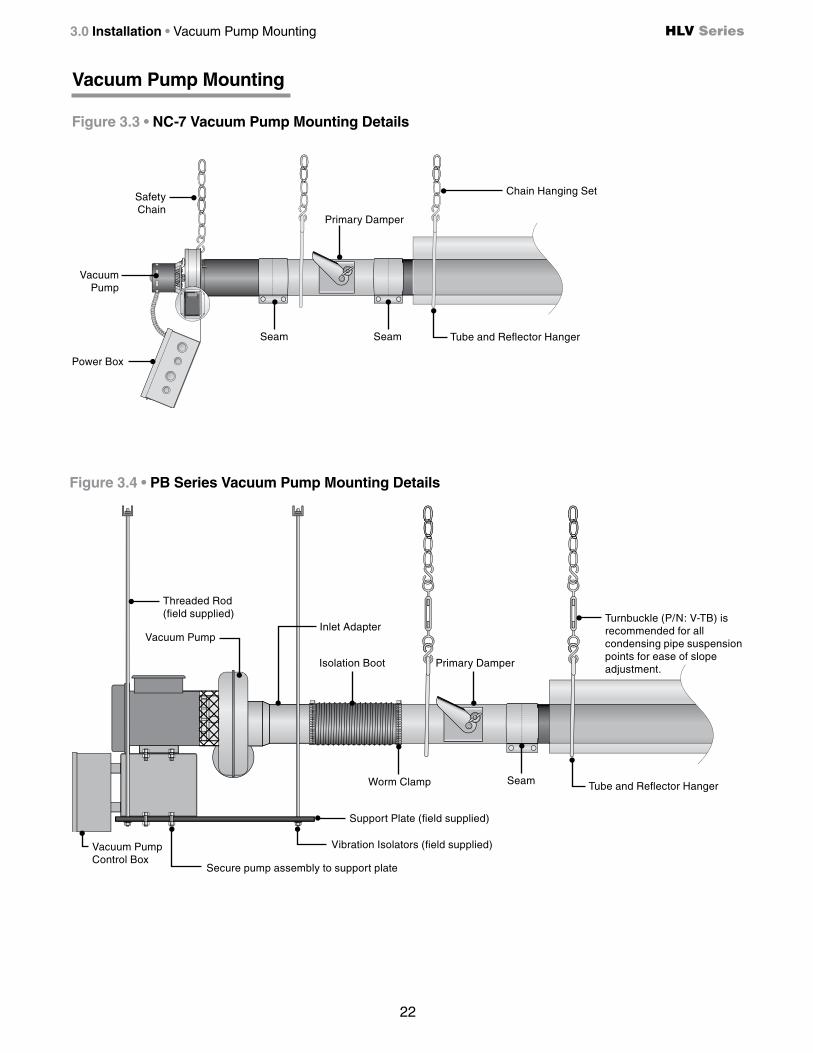
Figure 3.22 • Two-Stage System Field Wiring Diagram
Wiring
Figure 3.23 • Single-Stage System Field Wiring Diagram (V-1SAO)
VACUUM PUMP CONTROL BOX
(MOUNTED TO PUMP)
N-
120V
24V
+
L1
1N 2
24V INPUT FOR ZONE
#2 (IF USED)
24V INPUT FOR ZONE
#1
A common wire is required for thermostats that require constant power.
1N 2
24V Two Stage Controller
24V OUT - Stage 2(High Fire)
24V OUT - Stage 1(Low Fire)
24V IN
Common
External Transformer(Field Supplied)
N-
120V
24V
+
L1
A common wire is required for thermostats that require constant power.
24V Two Stage Controller
24V OUT - Stage 2(High Fire)
24V OUT - Stage 1(Low Fire)
24V IN
Common
External Transformer(Field Supplied)
This shows additional wiring for systems that will operate on two temperature zones. NOTE: Do not exceed the total number of burners allowed per system as stated in Chart 2.3 on page 18.N
L1
G
VACUUM PUMP CONTROL BOX
(MOUNTED TO PUMP)
N-
120V
24V
+
L1
COM 24VAC
24V INPUT FOR ZONE
#2 (IF USED)
24V INPUT FOR ZONE
#1
A common wire is required for thermostats that require constant power.
24V Digital Thermostat
W
R
Common
External Transformer(Field Supplied)
N-
120V
24V
+
L1
A common wire is required for thermostats that require constant power.
24V Digital Thermostat
External Transformer(Field Supplied)
This shows additional wiring for systems that will operate on two temperature zones. NOTE: Do not exceed the total number of burners allowed per system as stated in Chart 2.3 on page 18.
COM 24VAC
COM 24VAC
COM 24VAC
W
R
Common
N
L1
G

36
HLV Series3.0 Installation • Electrical Requirements • Internal Wiring
Before field wiring this appliance - Check existing wiring; replace if necessary.
NOTE: If any of the original wire supplied with the appliance must be replaced, it must be replaced with wiring material having a temperature rating of at least 105° C.
Figure 3.24 • Internal Burner Control Box Block Wiring Diagram
G
G
SINGLE STAGE ONLY (V-1SAO)*WIRE REMOVED

37
HLV Series 3.0 Installation • Electrical Requirements • Internal Wiring
Before field wiring this appliance - Check existing wiring; replace if necessary.
NOTE: If any of the original wire supplied with the appliance must be replaced, it must be replaced with wiring material having a temperature rating of at least 105° C.
Figure 3.25 • Internal Burner Control Box Ladder Wiring Diagram
120VAC
24VAC
BK
G
BK
G
SINGLE STAGE ONLY (V-1SAO)*WIRE REMOVED

38
HLV Series3.0 Installation • Electrical Requirements • Pump & Panel Wiring
120V
(23
0V O
pt.)
TR
AN
SF
OR
ME
R
24V
BL
4
3
2
1
2468
124V COIL
0
NC
NO
COM
24V COIL
COM
24V COIL
NO
NC
(IF USED)
24V INPUT FOR ZONE #1
O GY
GY
O
R
N
G
L1 R
W
230VAC INPUT OPTIONAL
(FACTORY ORDERED)
W
G
BL
BL
YY
BL
BL
R
RW
BK
BL
W
24V INPUT FOR ZONE #2
120VAC
NOTE: In North America, the pump and panel are pre-wired at the factory for 120V. If an alternate voltage is to be used consult the factory.
Wiring from the power supply to the panel and pump must be 12 AWG or larger to maintain proper voltage under full load conditions.
The circuitry for the panel and pump is suitable for a 20 AMP circuit maximum.
Figure 3.26 • Pump and Panel Assembly Internal Wiring

39
HLV Series 3.0 Installation • Gas Supply
Gas Supply
WARNING!
Improperly connected gas lines may result in fire, explosion, poisonous fumes, toxic gases, asphyxiation or death. Connect gas lines in accordance to national, state, provincial and local codes.
The installation must conform with local building codes or, in the absence of such codes, the National Fuel Code (NFPA 54) and in conjunction with ANSI Z21.24/CSA 6.10 “Connectors for Gas Appliances”.Important! Before connecting the gas supply to the burner control box: • Verify that the heater’s gas type (as listed on the rating plate) matches that of your application. NOTE: Unless otherwise noted on the rating plate, this infrared heater is designed and orificed to operate on standard BTU gas. Contact the factory if utilizing non-standard BTU gas.
• Check that the gas piping and service has the capacity to handle the total gas consumption of all heaters being installed, as well as any other gas appliances being connected to the supply line.
• Check that the main gas supply line is of proper diameter to supply the required fuel pressures.
• If utilizing used pipe, verify that its condition is clean and comparable to a new pipe. Test all gas supply lines in accordance with local codes.
• Test and confirm that inlet pressures are correct. Refer to the heater rating plate for gas type and the required minimum and maximum pressures (Chart 3.5). The gas supply pipe must be of sufficient size to provide the required capacity and inlet pressure to the heater (if necessary, consult the local gas company). Do not exceed the maximum allowed pressures for the heater, the space or the gas piping system.
Type of GasRequired Manifold
PressureMinimum Inlet
PressureMaximum Inlet
Pressure
Natural 3.5 Inches W.C. 5.0 Inches W.C. 14.0 Inches W.C.
Propane 10.0 Inches W.C. 11.0 Inches W.C. 14.0 Inches W.C.
Chart 3.5 Manifold Pressure
NOTE: Check manifold pressure at the tap on the gas valve. Small variations in manifold pressure (actual vs. published) may exist due to changing atmospheric conditions. Readings will be above atmospheric pressure.

40
HLV Series
IMPORTANT! The heating system will expand and contract during operation. Allowances for expansion must be made between the connection to the heater and the gas supply. Excessive bending, kinks, twists or vibration must be avoided. A flexible gas connection of approved type is required. Flexible stainless steel gas connectors installed in one plane, and without sharp bends, kinks or twists is recommended.
3.0 Installation • Gas Supply
WARNING!An approved connector, suitable for the environment of equipment usage, is required. Visible or excessive swaying, flexing and vibration of the gas connections must be avoided to prevent failure. In no case shall the gas or electrical supply support the weight of the heater.
The gas pipe and connection must be supported independently. Do not install gas supply line in a manner that bears the weight of the heater. Connect the main gas supply line with an approved flexible connector (Figures 3.27-3.28) or, if national or local codes require rigid piping, a swing joint. Heater shall not be connected to the building piping system with rigid pipe or semi-rigid metallic tubing, including copper. When using such material, an intermediate connection device that allows for heater expansion must be used.
The gas outlet must be in the same room as the appliance and accessible. It may not be concealed within or run through any wall, floor or partition. When installing the heater in a corrosive environment (or near corrosive substances), use a gas connector suitable for the environment. Do not use the gas piping system to electrically ground the heater.
1 Install a sediment trap / drip leg if condensation may occur at any point of the gas supply line or as required. This decreases the possibility of loose scale or dirt in the supply line entering the heater’s control system and causing a malfunction. NOTE: High pressure gas above 14 Inches W.C.. (water column pressure) requires a high pressure regulator and ball valve.
2 Form the stainless steel flexible connector into a smooth C-shape allowing 12 in. between the flexible connector’s end nuts (Figures 3.27-3.28).
3 Attach the ball valve to the gas supply pipe. Apply pipe compound to NPT adapter threads to seal the joint. Use only a pipe compound resistant to LP. NOTE: Provide a 1/8 in. NPT plugged tapping accessible for test gauge connection immediately upstream of gas connection to the heater (provided on ball valve).
4 Attach the flexible connector to the adapter and burner control box inlet. Seal the joints. Note: Excessive torque on the manifold may misalign the orifice. Always use two wrenches to tighten mating pipe connections.
5 Final assembly must be tested for gas leaks according to NFPA 54 and all local codes and/or Standards.
WARNING!
Testing for gas leaks with an open flame or other sources of ignition may lead to a fire or explosion and cause serious injury or death. Test in accordance with relevant codes of practice.
41
HLV Series 3.0 Installation • Gas Supply
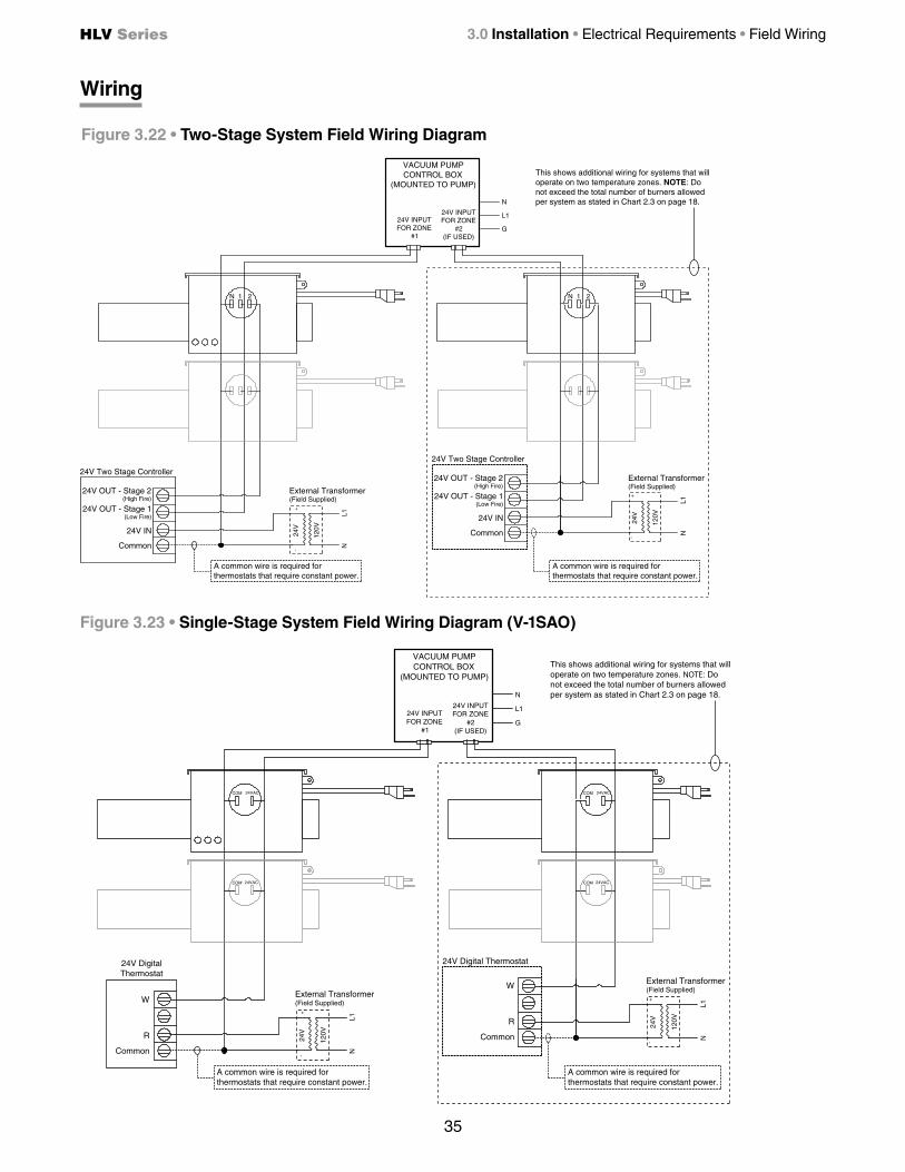
Figure 3.27 • Flexible Gas Connection • Side View
12”
Ball Valve / Inlet Tap
Flexible Gas Connector
Adapter
45°
Remove cap to clean sediment trap
Horizontal
45°
2 in. max displacement
Drip Leg/Sediment Trap
Heater Movement
Adapter
Burner Control Box
Burner Control Box
Ball Valve / Inlet Tap
Figure 3.28 • Flexible Gas Connection • Rear View
NOTE: Do not exceed 14 Inches W.C. to the appliance.
Flexible Gas Connector
42
HLV Series
WARNING!
Burner Lighting Instructions
1 Purge main gas supply line.
2 Rotate heater’s manual ball valve to the “ON” position.
3 Close electrical circuit (turn on thermostat).
4 If the burner fails to light, turn “OFF” gas and wait five minutes before repeating the above procedure.
Burner Shutdown Instructions
1 Open electrical circuit (turn off thermostat).
2 Rotate heater’s manual ball valve to the “OFF” position.
4.0 Operation • Lighting and Shutdown • Sequence of Operation
4.0 Operation
This heater must be installed and serviced by trained gas installation and service personnel only.
Do not bypass any safety features or the heater’s built in safety mechanisms will be compromised.
Sequence of Operation
Starting Circuit: Upon a call for heat, power is supplied to the relays at the burner box(es) and vacuum pump. The vacuum pump is energized creating negative air pressure. This allows the differential pressure switch in the burner box(es) to close which completes a low voltage circuit from the secondary side of the transformer to the ignition module. After the ignitor has been powered for seven seconds, the gas valve opens initiating the ignition trial. If flame is not sensed after 15 seconds, the heater will attempt to re-ignite for a total of three trials for ignition before entering lockout mode.
Single Stage Running Circuit: After ignition, the flame rod monitors burner flame. If sense of flame is lost, the control closes the gas valve within one second and a new trial sequence (identical to the starting sequence) is initiated. The control can be reset by briefly interrupting the power source.
Two Stage Running Circuit (when applicable): The second stage on the gas valve is powered directly from the second stage of the thermostat. In order for two stage to flow to a higher output, single stage must be energized as well. The thermostat determines which stage to maintain for the desired temperature.

43
HLV Series 3.0 Operation • Thermostat • Diagnostics • Operation Indicator Lights
Chart 4.1 • Control Module Diagnostic Flash Codes
LED Flash Code Fault StatusSteady ON Control Fault
1 Flash Air Flow Fault
2 Flashes Flame - No call for heat
3 Flashes Ignition Lockout
Figure 4.1 • Operational Indicator Lights
Light 1* (amber)Indicates High
Fire Mode
Light 2 (amber) Indicates Low
Fire Mode
Light 3 (amber)Pressure Switch
Operational Indicator Lights
Thermostat
NOTE: Different thermostats operate according to their particular features. Refer to thermostat specifications for details.
HLV Series heaters require a 24V, two stage thermostat to operate. The burner control box is equipped with a round terminal strip that accepts three (3) 1/4” insulated female spade terminals. Do not supply 120V to the 24V connection.
Theoretical Example: The thermostat is set to 65° F. The thermostat’s preset differential for high fire mode is 3° F.
When the temperature drops below the setpoint of the thermostat (65° F), low fire will activate. If the temperature continues to drop below the setpoint by another 3° F (62° F), high fire will activate bringing the temperature back up to the thermostat’s setpoint.
Diagnostics
The controls will automatically lockout the heater system when an external or system fault occurs.
Lockout: If proof of flame is not established, a component failure occurs or blockages are evident, the heater will enter hard lockout. If lockout occurs, the control can be reset by briefly interrupting the power source. Refer to Chart 4.1 below for a description of the control module diagnostic indicator flash codes.
* Models with V-1SAO add-on are not equipped with high fire light.
NOTE: Flash code indicator light is located internally on the control module.

44
HLV Series4.0 Operation • System Start-Up and Damper Adjustment
System Start-Up Prechecks
• Confirm all gas piping, electrical wiring, etc. are properly installed.
• Preset the primary and secondary damper(s) to half-open.
• If applicable, unassisted combustion air ducts must be installed before start-up.
• If applicable, fan assisted outside combustion air ducts must not be connected to burner control box upon initial start-up.
Damper Adjustment
1 The system must run for 20 minutes in high fire mode before setting the dampers. Confirm all operational indicator lights (located on the burner control box) are on.
2 All system dampers are preset to half-open. If a burner fails to stay lit or does not light, the damper serving that burner must be adjusted until the burner is continually lit throughout the initial 20 minute start-up.
3 Using a manometer with an adequate range, measure the vacuum pressure (Figure 4.2) at the burner furthest from the vacuum pump. Adjust the primary damper at the pump until the manometer reaches the specified reading shown in Chart 4.2.
NOTE: If proper box static pressure cannot be achieved, it may be necessary to remove one, two or all three baffle sections (P. 27). Consult factory following basic troubleshooting (i.e. proper pump rotation, check for blockages, baffle installed correctly, control box covers are secured, etc.).
Chart 4.2 • Burner Box Pressure Setpoints
Burner Box Input (BTU/h) Box Pressure (inches W.C.)
40,000 to 60,000 -0.51 +/- .01
75,000 to 110,000 -0.19 +/- .01
120,000 to 180,000 -0.22 +/- .01
200,000 -0.19 +/- .01
The system must operate in high fire for 20 minutes before adjusting the dampers. Each system damper must be adjusted to the box pressure setpoints listed above.
4 If secondary dampers are installed in the system, connect manometer to each applicable burner and set applicable secondary damper to the specified reading (Chart 4.2). 5 Once each damper has been adjusted, burner pressures must be checked to confirm initial setpoints did not change. Readjust dampers as necessary in the same order. Lock dampers in place.
6 If fan assisted outside air ducts are used, connect to control box after initial start-up is complete;
Adjust supply dampers (supplied with powered air inlet P/N: V-PAI - sold separately) until the required pressures are achieved.
Figure 4.2 • Burner Control Box Vacuum Port
Vacuum Port
NOTE: Remove the plug on vacuum port to measure box pressure. Ensure burner box lid is tightened securely.

45
HLV Series 5.0 Maintenance • Routine Inspection
5.0 Maintenance
WARNING!
Personal injury or death may result if maintenance is not performed by properly trained gas installer or service personnel. Contact the installing distributor or place of purchase for service. Do not operate heating system if repairs are necessary.
Allow heater to cool prior to servicing.
Disconnect power to heater before servicing.
Use protective glasses when maintaining the heater.
Routine Inspection: At least once per year, the heating system should be inspected and serviced by trained gas installation and service personnel only. This inspection should be performed at the beginning of the heating season to insure that all heater components are in proper working order and that the heating system operates at peak performance. Particular attention should be paid to the following items.
• Vent pipe system: Check the outside termination and the connections at the heater. Inspect the vent exhausts for leakage, damage, fatigue, corrosion and obstructions. If dirt becomes a problem, installation of outside air intake ducts for combustion is recommended.
• Combustion air intake system (when applicable): Check for blockage and/or leakage. Check the outside termination and the connection at the heater.
• Heat exchangers: Check the integrity of the heat exchangers and tailpipe. Replace if there are signs of structural failure. Check for corrosion and/or buildup within the tube exchanger passageways.
• Burner: Check for proper ignition, burner flame and flame sense. Flame should extend directly outward from burner without floating or lifting.
• Exhauster: Inspect the exhauster system for abnormal noise and/or vibrations. Consult factory for troubleshooting.
• Wiring: Check electrical connections for tightness and/or corrosion. Check wires for damage.
• Gas Connection: Inspect the integrity of the gas connection to the heater. Check for leaks, damage, fatigue or corrosion. Do not operate if repairs are necessary and turn off gas supply to the heater. Contact service personnel.
• Reflectors: To maintain effective infrared heating, always keep both sides of the reflector clean. Maintenance can vary significantly depending on the environment. Dirt and dust can be vacuumed or wiped with a soap and water solution. Use metal polish if the reflectors are severely dirty.
Contact service personnel if repairs are necessary. Do not operate unit.

46
HLV Series
Does the ignitor warm up and glow red?
Does the exhauster fan turn on?
5.0 Maintenance • Troubleshooting Guide
Turn up thermostat
Is the power at the exhauster 120V/220V?No Yes
Continued on page 48
No
Is the thermostat supplying 24V to the exhauster control panel?
Find the source of the electrical problem
No
Is power at the burner control box 120V/220V?No
Yes
Is the thermostat supplying 24V to the terminal plug on the
burner control box?
Yes
No
Find the source of the electrical problem.
Yes
No
Find the source of the electrical problem between the thermostat
transformer, thermostat and panel.
Yes
Replace the pressure switch after verifying:
• Baffle(s) are in the radiant tube furthest from the burner. • Heater, fan blowers ,squirrel cage, intake and exhaust are clean and free from dirt and obstructions. • The 4” air intake pipe does not exceed 20 ft. and/or 2 elbows. • There is not a negative pressure experienced at the area of air intake (e.g.; high winds, attic space, tightly sealed building).
After the ignitor is fully energized, does the gas
valve open?
Yes
Test for 24V at valve opening period (usually 5 seconds after power to the burner control box). Is there 24V at the valve?No
Replace circuit board and/or wiring harness.
Yes
Check to confirm gas pressure is within minimum and maximum inputs
as indicated on the heater’s rating plate. Is gas pressure OK?
No
Correct problem.
Replace gas valve.
Yes
No
Find the source of the electrical problem between the thermostat
transformer, thermostat and panel.
HLV Series Troubleshooting Guide
Yes

NOTICE Bypassing any switch is intended for testing purposes only. Do not leave switch bypassed during normal operation or the heater’s built-in safety mechanisms will be compromised.
47
HLV Series
After the system has run for 20 minutes in high fire mode, measure box pressures using a manometer with an adequate range.
Do the setpoints correspond with Chart 4.2 on page 44?
5.0 Maintenance • Troubleshooting Guide
Is the panel supplying 120V/220v to the exhauster?
Is there 24V on the secondary side of the transformer located in the panel assembly?
No
Yes
The exhauster is faulty and must be replaced.
Replace transformer.
No
Yes
A faulty relay may exist in the panel assembly. Consult factory.
Is the ignitor physically damaged?
Replace ignitor.
Yes
Check voltage during ignition sequence (usually 5 seconds after power to burner control box). Is it 24V?
No
Is the resistance through the ignitor 1 to 6 Ω ?
Replace faulty wiring.
Replace ignitor.
Yes
No Yes
Is the inlet or the outlet of the unit obstructed?
No Remove obstruction.
Yes
Check for loose wiring or restrictions in hose connections to the pressure switch. Are they OK?
No
Repair wiring or hose connections.
Yes
Temporarily place a jumper across the terminal of the safety pressure switch.
Set control box cover in place. Does the ignitor glow red?
Yes NoAdjust dampers until proper box pressures
are achieved.
Yes
Is there 24V on the secondary side of the
transformer in the burner control box?
Replace faulty transformer. Note: The original transformer is equipped with an automatic
resetting fuse. Confirm fuse has not been tripped.
No
No
Yes
Is there 24V between L1 and ground at the
circuit board?
No
Replace faulty wiring.
No
Replace circuit board.
Yes
*
*

48
HLV Series5.0 Maintenance • Troubleshooting Guide
Does the burner stay on?
Does the burner stay on for approximately 15 seconds
and then shut off?
Does the burner come on and turn off immediately
(1 or 2 seconds)?
Does the heater stay ON until a call
for heat ends?
Troubleshooting ends.
The heater can shut down due to: • Improper grounding. • High winds. • Taking combustion air from the attic. • Dirty environment. • Improperly positioned baffles (if applicable). • Fluctuating gas pressure. • Reduction of negative pressure as the system heats up (reset dampers).
No
Yes
No
Yes
Continued from page 46
Is the heater properly grounded? Is the polarity correct?
Correct problem.
No
Yes
Check to confirm gas pressure is within minimum and maximum
inputs as indicated on the heater’s rating plate. Is gas pressure OK?
No
Yes
YesRemove restriction in the exhaust or replace the faulty
pressure switch.
No
Yes
Does the burner light?
Is the ball valve in the ON position?
No
Check to confirm gas pressure is within minimum and maximum
inputs as indicated on the heater’s rating plate. Is gas pressure OK?
Yes
Correct problem.
Yes No
Correct problem.
No
Purge gas lines of air.
Yes
No

49
HLV Series 5.0 Maintenance • Troubleshooting Guide
This model has a flame rod sensor located next to the hot surface ignitor.
With an amp meter, check the amperage at the flame rod.
Is it greater than 7 amps?
YesConfirm the flame sensor wire is
OK and then replace circuit board.
The sensing rod is faulty or the flame is weak. Confirm that the heater is
operating at proper gas pressures as indicated on the heater’s rating label.
Replace sensing rod if necessary.
No

1283221222
111250
321
1229
1297
50
HLV Series
Chart 5.1 • Parts List
5.0 Maintenance • Parts • Heater Burner Assembly Components
1NOPS
207
97
218
219
15021251
83270
828
8251526A329
114
31B68A
33B
83
212
208A
1540A/1541A
223204
200A/201B
303
12
9 10
217
51280
1514
16
21B
222A
214
Figure 5.1 • Burner Assembly Components
304, 1204
76
31B
13
17
301
Part No. Description Part No. DescriptionTP-1 Control Box Cover TP-76 Rubber GrommetTP-5 Flange Gasket TP-82 Reflector Center Support (RCS)TP-9 Conduit Coupling TP-83 24 in. Stainless Steel Flexible Gas ConnectorTP-10 Conduit 4” x 1/2” TP-84 1/2 in. Female / Male Flare FittingTP-11 Mini Ignitor Box TP-85 1/2 in. Male / Male End FittingTP-12 Mini Ignitor Box Cover TP-97 1/4” x 1/4” Brass Int./Ext. Atmos. Barb FittingTP-13 8 x 1/2” Self-Drilling Screw (Qty. 4) TP-105 Aluminum Reflector End CapTP-14 Sight Glass Gasket TP-106 Reflector End Cap Clips (Qty. 8)TP-15 Sight Glass TP-113 Reflector Tension SpringTP-16 Sight Glass Washer TP-114 Plastic Air Orifice with ScreenTP-17 Sight Glass Kit TP-200A Low BTU Burner (Blue) - consult factoryTP-19B 4 in. Wire Hanger with Tension Spring TP-201B Mid BTU Burner (Tan) - consult factoryTP-20C 120 in. Aluminum Reflector TP-204 Gas Orifice (consult factory)TP-20D 120 in. Optional Stainless Steel Reflector TP-207 Pressure Switch Mounting BracketTP-21B 4 in. Standard Tube Clamp TP-208A Gas Valve Mounting BracketTP-26A 10 ft. Black Coated Aluminized Radiant Tube TP-212 1/2” x 3” Pipe NippleTP-26B 10 ft. Black Coated Alum-Ti Combustion Tube TP-214 Mini Ignitor Wiring HarnessTP-26C 10 ft. Uncoated Hot-Rolled Radiant Tube TP-217 Pressure Switch BarbTP-26H 10 ft. 304 UC Stainless Steel Condensing Pipe TP-218 Differential Switch Vinyl Sensing Tube (exhaust)TP-31B Control Box Mounting Bracket (Qty. 2) TP-219 Differential Vinyl Sensing Tube (burner)TP-33B 1/2 in. Shut-Off Ball Valve / Inlet Tap TP-220 Stainless Steel Tube Clamp (175 & 200 MBH burners)TP-65I 36 in. Interlocking Turbulator Baffle TP-221 Mini Ignitor Holder GasketTP-68A Strain Relief Bushing TP-222 Flame RodTP-70 Control Box Cover Gasket (per foot**) TP-222A Flame Rod Wire
** 6 feet total required to cover outer edges of the burner control box.
Replacement Parts
84
333
13
85

106
105
26B
21B/220
20C/20D
82
26H65I
V55A/V56A/V57A
V-23
V-24
V-D/V-D-SS
V301/V302/V3031289
1215/1255
1565
826
8321527
1525
1528
1566
26A/26C
21B
1516B/1516C/1516D
19B113
579
51
HLV Series
Figure 5.2 • Tube & Reflector Components
5.0 Maintenance • Parts • Tube and Reflector Components
Combustion Chamber(s)
Radiant Emitte
r Tube(s)
Condensing Tailpipe
Part No. Description Part No. DescriptionTP-223 Gas Manifold TP-1516D 1 HP PB-10A MotorTP-301 Burner Control Box Center Panel TP-1525 Vacuum Exhauster RelayTP-303 End Panel, Right TP-1526A 75VA Transformer with Foot MountsTP-304 Burner Control Box Outer Shell (50-175MBH) TP-1527 24V Switching Control RelayTP-321 Ignition Plate Gasket TP-1528 Exhauster Post Purge Relay TimerTP-329 1/4 in. Neutral Terminal Block TP-1540A 36G54-224 Gas Valve - Natural Gas AssemblyTP-333 72 in. 120V -Prong Power Cord TP-1541A 36G54-226 Gas Valve - LP Gas AssemblyTP-579 4 in. Wire Hanger TP-1565 8” x 8” Electrical BoxTP-825 24V Isolation HLRB Relay Board TP-1566 Exhauster Control Panel AssemblyTP-826 40VA Transformer TP-NOPS Normally Open Pressure Switch (see below)TP-828 Yellow Operational Indicator Light TP-264B Differential Pressure Switch, 40 to 80 MBHTP-832 Thermostat Terminal Strip TP-264E Differential Pressure Switch, 90 to 125 MBHTP-1204 Burner Control Box Outer Shell (200MBH) TP-1264A Differential Pressure Switch, 140 to 180 MBHTP-1215 NC-7 Exhauster Pump TP-264F Differential Pressure Switch, 200 MBHTP-1229 Fuse Holder V-D Damper (NC-7 pumps)TP-1250 24V Mini Ignitor V-D-SS Damper (PB Series pumps)TP-1251 Triton 6465H Circuit Board V-23 Isolation Boot (pump inlet and outlet) (Qty. 2)TP-1255 NC-7 Pump Assembly w/ Control Panel V-24 Worm Gear ClampTP-1280 16 in. Flanged Burner Tube with Fittings V-55A 4 in. Adapter for PB-8 (Qty. 2) or PB-9 (Qty. 1)TP-1283 Mini Ignitor Plate V-56A 5 in. Adapter for PB-9 (Qty. 1) or PB-10 (Qty. 1)TP-1289 NC-7 Exhauster Pump Mounting Tube V-57A 6 in. Adapter for PB-10 (Qty. 1)TP-1297 Fuse V-301 PB-8 Pump Assembly (panel & accessories not included)
TP-1502 End Panel, Left V-302 PB-9 Pump Assembly (panel & accessories not included)
TP-1516B 1/2 HP PB-8 Motor V-303 PB-10A Pump Assembly (panel & accessories not included)
TP-1516C 3/4 HP PB-9 Motor

© 2015 Detroit Radiant Products Co.21400 Hoover Road • Warren, MI 48089
Phone: (586) 756-0950 Fax: (586) 756-2626 www.detroitradiant.com • [email protected] in U. S. A.
6.0 Limited Warranty • Kit Contents Check List HLV Series
One-Year Limited Warranty. Radiant Tube Heaters covered in this manual, are warranted by Detroit Radiant Products Company to the original user against defects in workmanship or materials under normal use for one year after date of purchase. Any part which is determined to be defective in material or workmanship and returned to an authorized service location, as Detroit Radiant Products Company designates, shipping costs prepaid, will be, as the exclusive remedy, repaired or replaced at Detroit Radiant Products Company’s option. For limited warranty claim procedures, see PROMPT DISPOSITION below. This limited warranty gives purchasers specific legal rights which vary from jurisdiction to jurisdiction.
Additional Limited Warranty. In addition to the above mentioned one-year warranty, Detroit Radiant Products Company warrants the original purchaser five years on the combustion chamber, five years on aluminized steel radiant tubes (three years on hot-rolled steel radiant tubes and condensate pipe) and ten years on the stainless steel burner.
General Conditions. The Company will not be responsible for labor charges for the analysis of a defective condition of the heater or for the installation of replacement parts. The warranties provided herein will not apply if the input of the heater exceeds the rated input at time of manufacturing or if the heater in the judgment of the Company has been subjected to misuse, excessive dust, improper conversion, negligence, accident, corrosive atmospheres, excessive thermal shock, excessive vibration, physical damage to the heater, alterations by unauthorized service personnel, operation contrary to the Company’s instructions or if the serial number has been altered, defaced, or removed. The Company shall not be liable for any default or delay in the performance of these warranties caused by contingency beyond its control, including war, government restriction or restraints, strikes, fire, flood, short or reduced supply of raw materials, or parts.
The warranties herein shall be null and void if the heater is not installed by a competent heating contractor and/or if the heater is not installed according to Company instructions, normal industry practices and/or if the heater is not maintained and repaired according to Company’s instructions. Normal product degradation and wear (rust, oxidation, etc.) does not constitute a material defect and applicable warranty claim.
Limitation of Liability. To the extent allowable under applicable law, Detroit Radiant Products Company’s liability for consequential and incidental damages is expressly disclaimed. Detroit Radiant Products Company’s liability in all events is limited to and shall not exceed the purchase price paid.
Warranty Disclaimer. Detroit Radiant Products Company has made a diligent effort to provide product information and illustrate the products in this literature accurately; however, such information and illustrations are for the sole purpose of identification, and do not express or imply a warranty that the products are merchantable, or fit for a particular purpose, or that the products will necessarily conform to the illustrations or descriptions. Except as provided below, no warranty or affirmation of fact, expressed or implied, other than as stated in the “LIMITED WARRANTY” above is made or authorized by Detroit Radiant Products Company.
Product Suitability. Many jurisdictions have codes and regulations governing sales, construction, installation, and/or use of products for certain purposes, which may vary from those in neighboring areas. While Detroit Radiant Products Company attempts to assure that its products comply with as many codes, it cannot guarantee compliance, and cannot be responsible for how the product is installed or used. Before purchase and use of a product, review the product applications, and all applicable national and local codes and regulations, and be sure that the product, installation, and use will comply with them.
Certain aspects of disclaimers are not applicable to consumer products: e.g., (a) some jurisdictions do not allow the exclusion or limitation of incidental or consequential damages, so the above limitation or exclusion may not apply to you: (b) also, some jurisdictions do not allow a limitation on how long an implied warranty lasts, consequently the above limitation may not apply to you: and (c) by law, during the period of this limited warranty, any implied warranties of implied merchantability or fitness for a particular purpose applicable to consumer products purchased by consumers, may not be excluded or otherwise disclaimed.
Prompt Disposition. Detroit Radiant Products Company will make a good faith effort for prompt correction or other adjustment with respect to any product which proves to be defective within limited warranty. For any product believed to be defective within limited warranty, first write or call dealer from whom the product was purchased. Dealer will give additional directions. If unable to resolve satisfactorily, write to Detroit Radiant Products Company at address below, giving dealer’s name, address, date and number of dealer’s invoice, and describe the nature of the defect. Title and risk of loss pass to buyer on delivery to common carrier. If product was damaged in transit to you file claim with carrier.
Registration. Register on-line at www.drp-co.com/warranty.
6.0 Limited Warranty


![Hardinge HLV H Manual[1] Copy](https://img.pdfslide.net/doc/110x75/5466c90eb4af9f5d3f8b5517/hardinge-hlv-h-manual1-copy.jpg)