Embed Size (px)
Citation preview
CMC Basic Specification
HMI Guideline
This document aims to create a safe Human-Machine
Interface design guideline, according to state-of-the-art
research and technologies. Even the best C-ITS application
can only produce a safety benefit when potential warnings
are recognised by the rider.
and reactions such as braking are prompted

HMI Guideline
CMC Basic Specification 2
Document Information
Document Title: HMI Guideline
Version: 1.0
Release Date: 11/12/2020
Disclaimer
This document has been developed within the Connected Motorcycle Consortium and might be further
elaborated within the consortium. The Connected Motorcycle Consortium and its members accept no
liability for any use of this document and other documents from the consortium.
Copyright Notification: No part may be reproduced except as authorized by written prior permission. The
copyright and the foregoing restriction extend to reproduction in all media. © 2020, Connected
Motorcycle Consortium.
HMI Guideline
CMC Basic Specification 3
Index
1 Preamble ......................................................................................................................... 4
2 Introduction ..................................................................................................................... 7
2.1 CMC - Connected Motorcycle Consortium ............................................................... 7
2.2 HMI approach of CMC .............................................................................................. 7
2.3 Scope of the Guideline ............................................................................................. 8
2.4 Chapter relations ...................................................................................................... 8
2.5 Procedure ................................................................................................................ 9
3 HMI Guideline: CMC statements on NHTSA HMI guideline ........................................... 11
3.1 Distraction .............................................................................................................. 11
3.2 General Workload Considerations .......................................................................... 14
3.3 Providing Riders With Information on System Function and System Messages ..... 15
3.4 Warning Stages ...................................................................................................... 16
3.5 Selection of Sensory Modality ................................................................................ 17
3.6 Using Color ............................................................................................................ 18
3.7 Selecting Character Height for Icons and Text ....................................................... 19
3.8 Characteristics of Legible Text ............................................................................... 20
3.9 Temporal Characteristics of Visual Displays ........................................................... 21
3.10 Perceived Urgency of Auditory Warnings ............................................................... 22
3.11 Perceived Annoyance of Auditory Warnings ........................................................... 23
3.12 Using Localization Cues to Indicate Direction ......................................................... 24
3.13 Presenting Warnings Using Speech Messages ...................................................... 25
3.14 Prioritizing Messages Presented to Riders ............................................................. 26
3.15 Using “Master” Warnings in Integrated Warning Systems ...................................... 27
3.16 Overview of the Human Factors for Connected Vehicles (HFCV) Integration
Architecture ...................................................................................................................... 28
Abbreviations ....................................................................................................................... 29

HMI Guideline
CMC Basic Specification 4
1 Preamble
Any rider assistance system that informs or warns the rider about a potential hazardous
situation, needs to focus on a proper human-machine interface (HMI) to deliver this warning in
a non-distractive and salient way. Consequently, the HMI is a highly relevant component of
any C-ITS application when it comes to the improvement of safety for Powered Two-Wheeler1
(PTW) riders. Therefore, the main aim of this document is to provide design guidance for HMIs
on PTWs for Cooperative Intelligent Transport Systems (C-ITS).
This document refers to the National Highway Traffic Safety Administration (NHTSA) guideline
“Human Factors Design Guidance For Driver-Vehicle Interfaces” 2 and has been commented
on by the Connected Motorcycle Consortium (CMC) to be applicable to PTWs. As the PTW
sector does not have sufficient research experience regarding this topic yet, a first step towards
a PTW specific HMI guideline is the assessment of an established HMI guideline from the car
sector as to the applicability to PTWs. The assessment has been done by HMI experts from
different PTW Original Equipment Manufacturers (OEMs) together with the Wuerzburg Institute
for Traffic Sciences (WIVW GmbH) as independent human factors research institute. The PTW
specific comments and recommendations are based on prior experience, OEM internal tests
and available literature or even studies conducted within the CMC.
The NHTSA guideline contains empirically proven HMI design recommendations that have
been gathered over decades. This sophisticated document was therefore chosen as the
baseline to start from. Modifications for the application of car guidelines to PTW are clearly
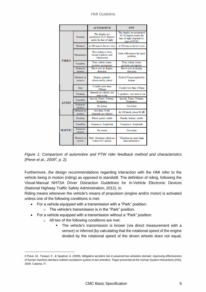
necessary, because there are major differences between the two vehicle concepts (Figure 1).
These differences concern ergonomics, available space for HMI applications, driver positioning
or influence of environmental conditions to name just a few of them.
This HMI guideline is only applicable to human-machine interfaces directly installed on the
PTW. It does not cover other fields of application such as devices installed in a PTW helmet.
Even if this might be a useful HMI design possibility one day, it is out of scope for this guideline.
1 Regulation (EU) No.168/2013
The target vehicles in this document are Powered Two-Wheelers (PTWs). PTW is used to refer generically to motorised two-
wheeled road-going vehicles, commonly called motorcycles or scooters. As defined by the European Commission, PTW includes
all two-wheel vehicles regardless of their engine capacity. However, this document can be extended to other vehicle types such
as three wheeled vehicles if the vehicle dynamics are similar to those of a PTW. 2 Campbell, J. L., Brown. J. L., Graving, J. S., Richard, C. M., Lichty, M. G., Sanquist, T., … & Morgan, J. L.. (2016). Human
factors design guidance for driver-vehicle interfaces (Report No. DOT HS 812 360). Washington, DC: National Highway Traffic
Safety Administration.
HMI Guideline
CMC Basic Specification 5
Figure 1: Comparison of automotive and PTW rider feedback method and characteristics
(Pieve et al., 20093, p. 2).
Furthermore, the design recommendations regarding interaction with the HMI refer to the
vehicle being in motion (riding) as opposed to standstill. The definition of riding, following the
Visual-Manual NHTSA Driver Distraction Guidelines for In-Vehicle Electronic Devices
(National Highway Traffic Safety Administration, 2012), is:
Riding means whenever the vehicle's means of propulsion (engine and/or motor) is activated
unless one of the following conditions is met:
For a vehicle equipped with a transmission with a “Park” position:
o The vehicle's transmission is in the “Park” position.
For a vehicle equipped with a transmission without a “Park” position:
o All two of the following conditions are met:
The vehicle's transmission is known (via direct measurement with a
sensor) or inferred (by calculating that the rotational speed of the engine
divided by the rotational speed of the driven wheels does not equal,
3 Pieve, M., Tesauri, F., & Spadoni, A. (2009). Mitigation accident risk in powered two wheelers domain: improving effectiveness
of human machine interface collision avoidance system in two wheelers. Paper presented at the Human System Interactions (HSI),
2009. Catania, IT.
HMI Guideline
CMC Basic Specification 6
allowing for production and measurement tolerances, one of the overall
gear ratios of the transmission/vehicle) to be in the neutral position,
and the vehicle's speed is less than 5 mph.
Some general comments regarding deviations between NHTSA’s publications and this CMC
document shall be made:
It must be stated that the original NHTSA document typically refers to English/
alphanumeric characters, but other languages / characters should be individually
considered in lingual condition/ criteria.
Moreover, we refer to the term rider whenever the original document refers to driver.
In general, the implementation of auditory warnings on a PTW is way more challenging
than in a car. As long as these technical challenges are not reliably solved, auditory
warnings cannot be recommended unrestrictedly for the variety of PTW types.
This HMI guideline contains design recommendations and examples to support PTW HMI
designers. The recommendations given are not mandatory but shall serve as support for the
design of PTW HMI concepts that offer ideal guidance to the rider while minimizing negative
aspects such as distraction.
HMI Guideline
CMC Basic Specification 7
2 Introduction
The following chapter contains a brief introduction of the CMC as well as the Task Group HMI
for C-ITS on PTW.
2.1 CMC - Connected Motorcycle Consortium
The CMC is a collaboration between manufacturers, suppliers, researchers and associations
to make PTW part of the future connected mobility. CMC is a non-profit organization
established by key motorcycle makers with the unilateral goal to promote and develop C-ITS
on a global scale.
CMC targets to improve PTW rider safety and comfort. Connected mobility / Vehicle-to-Vehicle
Communications / Cooperative Integrated Transportation Systems are being developed, but
PTW-specific safety aspects have not been taken into consideration sufficiently so far. CMC is
paving the way for PTW connectivity by making PTWs part of C-ITS and connected mobility.
CMC aims to create a common basic specification for PTW ITS, with as many cross-
manufacturer standards as possible.
The basis of CMC was laid in the year 2015 when the founding members BMW Motorrad,
Honda and Yamaha agreed upon the need to further enhance motorcycle/ scooter safety by
the means of C-ITS. This initial partnership has led to the establishment of CMC in 2016. Since
then, manufacturers, suppliers and research institutes joined forces to collaborate. 4
2.2 HMI approach of CMC
CMC investigates general features of PTW HMIs for C-ITS applications that all OEMs can rely
on. Topics to be addressed are, for instance, specific properties of visual warnings (e.g., flash
rate of warnings to maximize recognizability), or design recommendations regarding
information timing etc. The focus lies on the information flow between PTW and rider.
Therefore, results from psychological and cognitive ergonomic research are mainly considered.
The overall aim of CMC is to provide general recommendations on how to design PTW HMI
solutions for C-ITS applications.
4 Connected Motorcycle Consortium (https://www.cmc-info.net/ accessed on 02.11.2020)
HMI Guideline
CMC Basic Specification 8
2.3 Scope of the Guideline
This HMI guideline mainly applies to HMI design for C-ITS applications. Depending on the
specific topic, the scope might even go beyond pure C-ITS applications. For example, the
definition of a minimum character height limited by aspects of human eyesight, may also be
applied to other HMI design issues.
All topics are retrieved from the NHTSA Guideline “Human Factors Design Guidance For
Driver-Vehicle Interfaces”5 and have been analysed by a group of PTW HMI experts. The
necessary PTW-specific modifications were commonly developed in a series of workshops.
2.4 Chapter relations
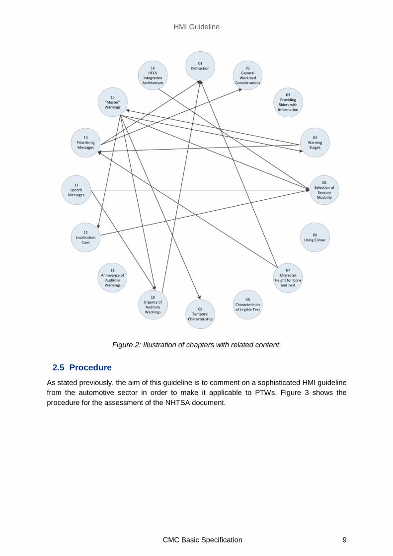
Figure 2 shows the relationship between different chapters in this document. This shall help
the reader to identify relevant chapters for a specific topic. For instance, if someone is
interested in Chapter 3.4 Warning Stages, the illustration shows that Chapters 3.14 and 3.15
dealing with prioritizing messages and using master warnings might also be relevant.
5 Campbell, J. L., Brown. J. L., Graving, J. S., Richard, C. M., Lichty, M. G., Sanquist, T., … & Morgan, J. L.. (2016). Human
factors design guidance for driver-vehicle interfaces (Report No. DOT HS 812 360). Washington, DC: National Highway Traffic
Safety Administration.
HMI Guideline
CMC Basic Specification 9
Figure 2: Illustration of chapters with related content.
2.5 Procedure
As stated previously, the aim of this guideline is to comment on a sophisticated HMI guideline
from the automotive sector in order to make it applicable to PTWs. Figure 3 shows the
procedure for the assessment of the NHTSA document.
HMI Guideline
CMC Basic Specification 10
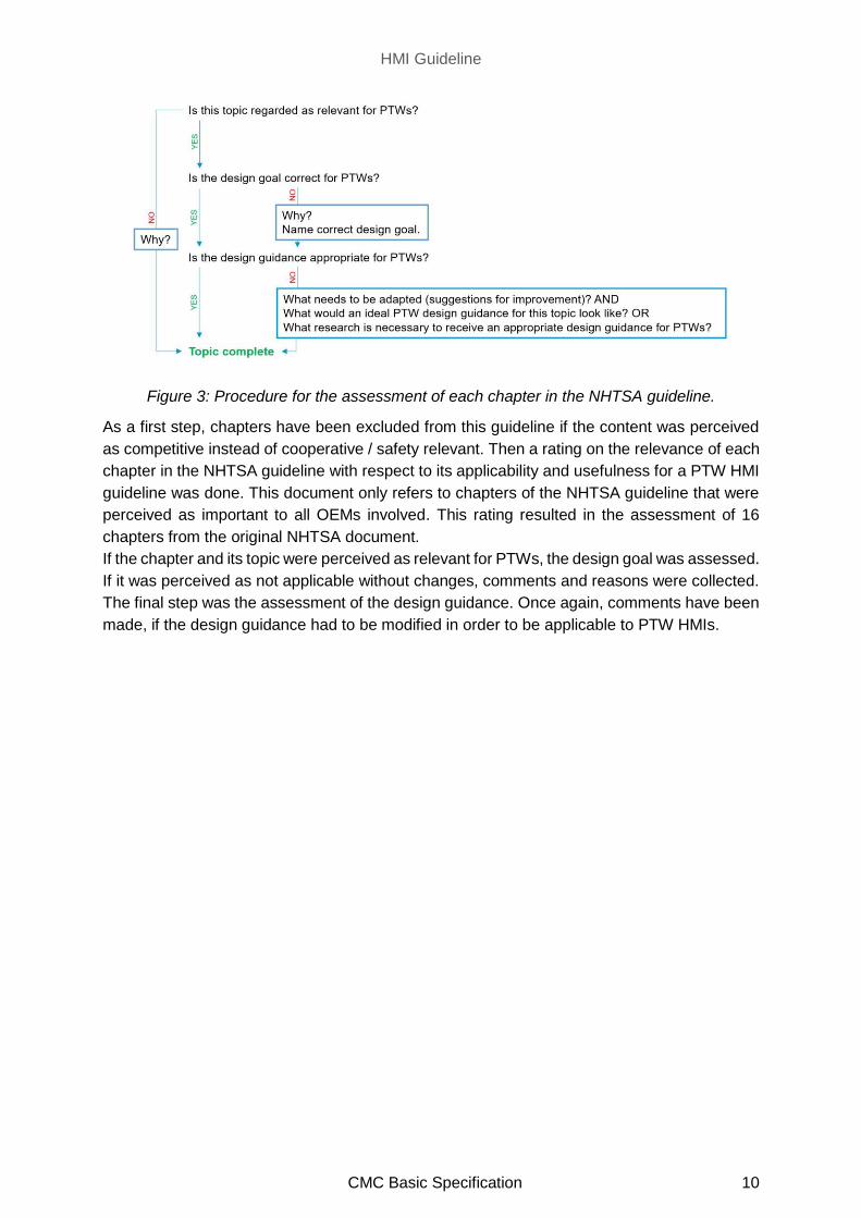
Figure 3: Procedure for the assessment of each chapter in the NHTSA guideline.
As a first step, chapters have been excluded from this guideline if the content was perceived
as competitive instead of cooperative / safety relevant. Then a rating on the relevance of each
chapter in the NHTSA guideline with respect to its applicability and usefulness for a PTW HMI
guideline was done. This document only refers to chapters of the NHTSA guideline that were
perceived as important to all OEMs involved. This rating resulted in the assessment of 16
chapters from the original NHTSA document.
If the chapter and its topic were perceived as relevant for PTWs, the design goal was assessed.
If it was perceived as not applicable without changes, comments and reasons were collected.
The final step was the assessment of the design guidance. Once again, comments have been
made, if the design guidance had to be modified in order to be applicable to PTW HMIs.
HMI Guideline
CMC Basic Specification 11
3 HMI Guideline: CMC statements on NHTSA HMI guideline
The following chapters contain general statements regarding the topic discussed together with
specific remarks on the original NHTSA guideline chapter. The title of each paragraph delivers
the reference between the NHTSA document and the CMC document.
3.1 Distraction
CMC suggests that, for safe riding, design consideration is required to consider that tasks and
messages do not divert attention from riding itself. As an example, a C-ITS visual feedback
device downward viewing angle influences the overall distraction, when the rider needs to look
far down from the forward line of sight. Nevertheless, it must be stated that a visual warning in
a non-ideal position is assumed to be better than no warning at all.
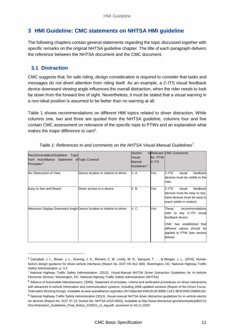
Table 1 shows recommendations on different HMI topics related to driver distraction. While
columns one, two and three are quoted from the NHTSA guideline, columns four and five
contain CMC assessment on relevance of the specific topic to PTWs and an explanation what
makes the major difference to cars6.
Table 1: References to and comments on the NHTSA Visual-Manual Guidelines7.
Recommendation/Guideline Topic
from AutoAlliance Statement of
Principles 8
Topic Covered
Section in
Visual-
Manual
Guidelines 9
Relevant
for PTW-
C-ITS
CMC Comments
No Obstruction of View Device location in relation to driver. V. A Yes C-ITS visual feedback
devices must be visible to the
rider.
Easy to See and Reach Driver access to a device. V. B Yes C-ITS visual feedback
devices must be easy to see,
input devices must be easy to
reach (while in motion)
Maximum Display Downward Angle Device location in relation to driver. V. C Yes These recommendations
refer to any C-ITS visual
feedback device.
CMC has established that
different values should be
applied to PTW (see section
below).
6 Campbell, J. L., Brown. J. L., Graving, J. S., Richard, C. M., Lichty, M. G., Sanquist, T., … & Morgan, J. L.. (2016). Human
factors design guidance for driver-vehicle interfaces (Report No. DOT HS 812 360). Washington, DC: National Highway Traffic
Safety Administration, p. 3-2. 7 National Highway Traffic Safety Administration. (2012). Visual-Manual NHTSA Driver Distraction Guidelines for In-Vehicle
Electronic Devices. Washington, DC: National Highway Traffic Safety Administration (NHTSA). 8 Alliance of Automobile Manufacturers. (2006). Statement of principles, criteria and verification procedures on driver interactions
with advanced in-vehicle information and communication systems, including 2006 updated sections (Report of the Driver Focus-
Telematics Working Group). Available at www.autoalliance.org/index.cfm?objectid=D6819130-B985-11E1-9E4C000C296BA163.
9 National Highway Traffic Safety Administration (2013). Visual-manual NHTSA driver distraction guidelines for in-vehicle electro
nic devices (Report No. DOT 37-13; Docket No. NHTSA-2010-0053). Available at http://www.distraction.gov/downloads/pdfs/113
02a-Distraction_Guidelines_Final_Notice_010815_v1_tag.pdf, accessed on 02.11.2020.

HMI Guideline
CMC Basic Specification 12
Lateral Position of Visual Displays Device location in relation to driver. V. D Yes Positioning the C-ITS visual
feedback device in the
forward line of sight. In terms
of lateral position this is easier
to be achieved for PTW than
for cars.
Minimum Size of Displayed Textual
Information
Size of visually presented text. V. E Yes Displayed textual information
must be readable.
Per Se Lock Outs Device usage while driving. V. F Yes Lock Outs are only relevant
for adjustments of settings of
C-ITS-functions (e.g.
adjusting which types of
warnings are active).
Acceptable Test-Based Lock Out of
Tasks
Tasks performed while driving. V. G No This topic is out of scope for
PTW-C-ITS.
Sound Level Sound level of a device. V. H Yes Should be considered at a
later stage. Acceptable level
for PTW shall be addressed.
For challenges see comments
on chapter 3.10.
Single-Handed Operation Driver control of the vehicle. V. I Yes C-ITS related input devices
should ideally be operated
with the left hand OR should
at least not require both
hands at a time (while in
motion).
Interruptibility Driver interaction with the device. V. J Yes It shall be possible to interrupt
visual-manual interaction with
the C-ITS device and
continue later.
Device Response Time Feedback provided to the driver by the
device.
V. K Yes Feedback must be clear and
timely.
Disablement Presentation of non-safety-related
information to the driver.
V. L Yes Both, safety and non-safety
related C-ITS applications
can be disabled.
Distinguish Tasks or Functions Not
Intended for Use While Driving
Driver access to devices while driving. V. M Yes A separation between
assessment of C-ITS warning
delivery while riding and tasks
not intended for use while
riding (e.g., change settings)
can be made.---
Device Status Presentation of system status
information.
V. N Yes The rider needs to recognize
whether the C-ITS application
is running.
Visual Task Completion Driver interaction with the device. - No This topic is out of scope for
PTW-C-ITS
Driving Relevant Information Information presented to the driver. - No This topic is out of scope for
PTW-C-ITS
Speech-Based Communication
Systems
Driver interaction with the device. - No This topic is out of scope for
PTW-C-ITS
Pace of Interaction with Device Driver interaction with the device. - No This topic is out of scope for
PTW-C-ITS

HMI Guideline
CMC Basic Specification 13
The recommendations cited above mainly deal with visual information. Due to the
fundamentally different vehicle concept in terms of vehicle geometry or ergonomics, it must be
assumed that no simple generalisation from car thresholds to PTW thresholds is possible10.
10 Pieve, M., Tesauri, F., & Spadoni, A. (2009). Mitigation accident risk in powered two wheelers domain: improving effectiveness
of human machine interface collision avoidance system in two wheelers. Paper presented at the Human System Interactions
Conference, 2009. HSI 09. Catania, IT.
HMI Guideline
CMC Basic Specification 14
3.2 General Workload Considerations
The NHTSA chapter focuses on information displays for secondary tasks. The adapted design
goal for CMC is the design of C-ITS feedback devices instead of information displays for
secondary tasks.
On top of that, CMC considers that the workload caused by the primary task (riding the PTW)
seems to be higher than the workload for driving a car11. For example, keeping stability of the
PTW is an additional part of the primary task which increases the default workload (compared
to a car, as considered by NHTSA guidelines).
Additionally, the option of reducing workload by sharing tasks with a co-driver (like in a 4-wheel
vehicle) is not possible in the PTW context. The rider must deal with all types of tasks (primary,
secondary), which increases the importance of thinking about workload when designing C-ITS
feedback devices.
11 Buld, S., Will, S., Kaussner, A., & Krüger, H.-P. (2014). Entwicklung eines Verfahrens zu Erfassung der Fahrerbeanspruchung
beim Motorradfahren (FE 82.0368/2009/). Bremen: Bundesanstalt für Straßenwesen.

HMI Guideline
CMC Basic Specification 15
3.3 Providing Riders With Information on System Function and System
Messages
CMC generally agrees with the introduction given by the NHTSA guideline having ABS as an
example. To establish applicability to PTWs in the C-ITS context, the example of EEBL
(Electronic Emergency Brake Light) can be used.
The EEBL application enables a vehicle to broadcast its own emergency braking situation to
the surrounding vehicles, including those that have their line of sight obstructed by other
vehicles or bad weather like fog or rain (© This picture was created using the C2C-CC Illustration Toolkit, owned by the
CAR 2 CAR Communication Consortium
Figure 4).
In case there are multiple vehicles driving behind each other, and the first vehicle has to
perform an emergency braking, this application drastically reduces the delay in reaction time
by subsequent vehicles: each driver / rider is informed immediately of the emergency braking
performed ahead, and the risk of collision could be avoided.
© This picture was created using the C2C-CC Illustration Toolkit, owned by the CAR 2 CAR Communication Consortium
Figure 4: Illustration of an EEBL scenario.
If provided with adequate information before riding (for example, via user manual or information
pamphlet), riders will know that they may need to take preventive actions (such as braking or
performing an evasive manoeuvre) when receiving an EEBL warning.
To provide riders with clear and concise information on system function, states, and how to
respond when the system activates, the method of the ABS example applies to C-ITS
applications for PTWs as well.

HMI Guideline
CMC Basic Specification 16
3.4 Warning Stages
CMC agrees to the chapter about warning stages. Nevertheless, it is important to point out that
warnings to prevent a collision are of more importance for PTW riders than for car drivers as
the risk of physical harm is higher.
CMC suggests considering the following examples for better understanding of two-stage
warnings and multi-stage warnings in the PTW context:
Consider using a two-stage warning:
o In situations where hard braking could have undesirable effects, (e.g. while
riding on low friction roads, which might induce slip and fall). Hard-braking may
be more likely with one-stage systems that only activate for imminent
situations.
Consider using a multi-stage graded warning system:
o When the situation evolves gradually (e.g., for stationary vehicle warning, if a
vehicle crashed or has broken down, it may be possible for the following
vehicles to implement an early warning that allows the riders to adjust their
behaviour to prevent hard braking or risky manoeuvres).
HMI Guideline
CMC Basic Specification 17
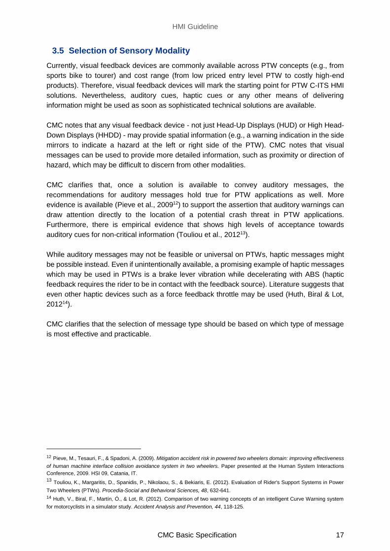
3.5 Selection of Sensory Modality
Currently, visual feedback devices are commonly available across PTW concepts (e.g., from
sports bike to tourer) and cost range (from low priced entry level PTW to costly high-end
products). Therefore, visual feedback devices will mark the starting point for PTW C-ITS HMI
solutions. Nevertheless, auditory cues, haptic cues or any other means of delivering
information might be used as soon as sophisticated technical solutions are available.
CMC notes that any visual feedback device - not just Head-Up Displays (HUD) or High Head-
Down Displays (HHDD) - may provide spatial information (e.g., a warning indication in the side
mirrors to indicate a hazard at the left or right side of the PTW). CMC notes that visual
messages can be used to provide more detailed information, such as proximity or direction of
hazard, which may be difficult to discern from other modalities.
CMC clarifies that, once a solution is available to convey auditory messages, the
recommendations for auditory messages hold true for PTW applications as well. More
evidence is available (Pieve et al., 200912) to support the assertion that auditory warnings can
draw attention directly to the location of a potential crash threat in PTW applications.
Furthermore, there is empirical evidence that shows high levels of acceptance towards
auditory cues for non-critical information (Touliou et al., 201213).
While auditory messages may not be feasible or universal on PTWs, haptic messages might
be possible instead. Even if unintentionally available, a promising example of haptic messages
which may be used in PTWs is a brake lever vibration while decelerating with ABS (haptic
feedback requires the rider to be in contact with the feedback source). Literature suggests that
even other haptic devices such as a force feedback throttle may be used (Huth, Biral & Lot,
201214).
CMC clarifies that the selection of message type should be based on which type of message
is most effective and practicable.
12 Pieve, M., Tesauri, F., & Spadoni, A. (2009). Mitigation accident risk in powered two wheelers domain: improving effectiveness
of human machine interface collision avoidance system in two wheelers. Paper presented at the Human System Interactions
Conference, 2009. HSI 09, Catania, IT. 13 Touliou, K., Margaritis, D., Spanidis, P., Nikolaou, S., & Bekiaris, E. (2012). Evaluation of Rider's Support Systems in Power
Two Wheelers (PTWs). Procedia-Social and Behavioral Sciences, 48, 632-641. 14 Huth, V., Biral, F., Martín, Ó., & Lot, R. (2012). Comparison of two warning concepts of an intelligent Curve Warning system
for motorcyclists in a simulator study. Accident Analysis and Prevention, 44, 118-125.
HMI Guideline
CMC Basic Specification 18
3.6 Using Color
CMC suggests using colour displays instead of monochrome displays for optimisation of C-
ITS information. Monochrome displays remain state of the art in some segments and are not
excluded by this recommendation and this recommendation does not preclude the inclusion of
C-ITS information in monochrome displays.
CMC clarifies that the quantity of colours used to code information is in addition to
monochromatic background information. This is to ensure that there is no misinterpretation
(and subsequent limitation) of using only two colours in addition to the monochrome
configuration.
- Correct example interpretation of the NHTSA chapter from CMC point of view: Four
colours (e.g., Red, Amber/Yellow, Green and Blue) may be used in addition to black
and white background information.
- Incorrect example interpretation of the NHTSA chapter from CMC point of view – Two
additional colours (e.g., Red and Amber/Yellow,) may be used in addition to black and
white background information
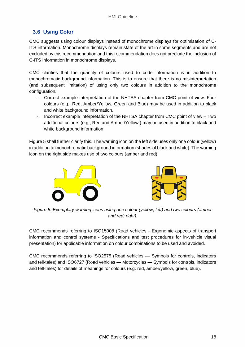
Figure 5 shall further clarify this. The warning icon on the left side uses only one colour (yellow)
in addition to monochromatic background information (shades of black and white). The warning
icon on the right side makes use of two colours (amber and red).
Figure 5: Exemplary warning icons using one colour (yellow; left) and two colours (amber
and red; right).
CMC recommends referring to ISO15008 (Road vehicles - Ergonomic aspects of transport
information and control systems - Specifications and test procedures for in-vehicle visual
presentation) for applicable information on colour combinations to be used and avoided.
CMC recommends referring to ISO2575 (Road vehicles — Symbols for controls, indicators
and tell-tales) and ISO6727 (Road vehicles — Motorcycles — Symbols for controls, indicators
and tell-tales) for details of meanings for colours (e.g. red, amber/yellow, green, blue).
HMI Guideline
CMC Basic Specification 19
3.7 Selecting Character Height for Icons and Text
CMC generally agrees with the introduction given by the NHTSA guideline. However, the C-
ITS visual feedback device used on PTWs is different from a car such as the effect by
environmental condition being more significant, e.g. direct sunlight, rain, etc. For the usage of
C-ITS visual feedback devices, a visual icon should be designed in a way that the icon itself
can be processed and the correct reactions are triggered without the necessity of reading a
text within the icon. Therefore, text within the icon is not considered for PTW C-ITS HMI
recommendations in this chapter.
Further, the more time critical the information, the closer it should be positioned to the optimum
field of view. This CMC recommendation provides a suggestion on where within a display
information or warnings shall be positioned. The location of the display itself is not a pure HMI
decision (e.g., aerodynamics, design etc.) and therefore out of scope for this document.
In addition, minimum visual angle of primary graphical elements mentioned in NHSTA
guideline has 34 arcminutes for non-time-critical applications, but it should be considered that
some C-ITS applications are time critical, which may result in different recommendations.
Further PTW-specific research is necessary to propose empirically based PTW thresholds.
HMI Guideline
CMC Basic Specification 20
3.8 Characteristics of Legible Text
CMC generally agrees to the chapter about “Characteristics of Legible Text” for Latin/ Roman
characters. For other languages/ characters different rules might apply.
ISO15008 contains details and recommendations on reproducibility of Latin and Non-Latin
characters which are applicable to consideration in this context.

HMI Guideline
CMC Basic Specification 21
3.9 Temporal Characteristics of Visual Displays
CMC conducted a motorcycle simulator study with N = 16 participants to investigate the
relationship between flash rate of visual warning icons and recognizability. With the given setup,
it showed that static warnings as well as warning icons with a flash rate of 1.5 Hz can be used
for advisory warnings as recognizability in the instrument cluster was on a comparable level.
From a subjective point of view, the riders preferred flashing icons for advisory warnings.
CMC would recommend that all motion cues that induce too much attraction (in addition to the
examples of “bouncing” and “zooming” as mentioned in the NHTSA guidelines) should not be
used.
HMI Guideline
CMC Basic Specification 22
3.10 Perceived Urgency of Auditory Warnings
CMC notes that, currently, visual interfaces are available across PTW concepts while technical
solutions to deliver auditory warnings at a required sound level and/or direction are not.
Depending on background noise, availability of a wind shield, type of helmet etc. the obstacle
to receive auditory warnings e.g., at 100 km/h is approx. 80 dB (Pieve et al., 200915; Schueler,
F., 200716). Even though there are technical constraints to overcome, the starting point for
auditory warnings on PTW applications should be the recommendations made within the
NHTSA guidelines until further research can be conducted.
A specific consideration for PTW implementation of auditory warnings is whether any market-
specific regulations exist, which prevent the use of audio devices integrated within rider
helmets (e.g., reliability of audio connection, battery level of exterior device). These devices
are not PTW-fixed and therefore out of scope for this document.
If no technical solution exists to deal with these challenges, CMC recommends to not use
auditory warnings. Generally, this holds true for all chapters dealing with auditory warning
design.
15 Pieve, M., Tesauri, F., & Spadoni, A. (2009). Mitigation accident risk in powered two wheelers domain: improving effectiveness
of human machine interface collision avoidance system in two wheelers. Paper presented at the Human System Interactions
Conference, 2009. HSI 09, Catania, IT. 16 Schueler, F. (2007). Anforderungen an Helme für Motorradfahrer zur Motorradsicherheit. Demands on helmets for active safety
of motorcycles. Berichte der Bundesanstalt für Straßenwesen, Reihe F: Fahrzeugtechnik (64).
HMI Guideline
CMC Basic Specification 23
3.11 Perceived Annoyance of Auditory Warnings
CMC agrees to the chapter content with the limitations already mentioned in chapter 3.10
Perceived Urgency of Auditory Warnings.
HMI Guideline
CMC Basic Specification 24
3.12 Using Localization Cues to Indicate Direction
The content of this chapter requires limitations discussed in chapter 3.10 (method of generating
sound which can be perceived by a PTW rider) to be overcome first.
Application specific limitations of generating sound which can be perceived to be from different
locations (in front or behind) could be problematic with current solutions available (i.e. helmet
mounted headset and speakers). Furthermore, one must also consider that, if information
comes from speakers within a helmet, the position/ orientation of the head may then differ to
the location of the object/ event the rider shall be made aware of.
Additionally, this chapter relates to chapter 3.5 Selection of Sensory Modality. As the
connection/ availability of headsets (if selected as the method of providing auditory warnings)
cannot be guaranteed, a warning strategy may require mitigation strategies to use other
redundant warning types.
HMI Guideline
CMC Basic Specification 25
3.13 Presenting Warnings Using Speech Messages
The method of implementing auditory messages is a significant primary subject to be resolved
in order to allow speech messages to be implemented.
Furthermore, CMC notes that the presented research focuses on English speech messages
and that there might be differences when other languages are used.
The guidance in this chapter is heavily affected by the comments on chapters 3.5 (Selection
of Sensory Modality) and 3.10 (Urgency of Auditory Warnings).

HMI Guideline
CMC Basic Specification 26
3.14 Prioritizing Messages Presented to Riders
Since the workload on PTWs seems to be higher than cars17, the message prioritization is
even more important on PTWs.
The original design guidance chapter referred to a dedicated visual screen for continuous
visual information, which might be a legacy from the 2002 standard of the NHTSA guideline,
where static (e.g., speedometer) and dynamic content was separated. Since displays can be
used to show static and/ or dynamic content, it is possible for continuous visual information
and other dynamic visual information (requested by the rider or regarding external environment
or hazard) to be shown on the same display.
The following examples might clarify different priority order indices (POI) criteria from PTW
point of view (Table 2).
Table 2: C-ITS application examples for message prioritization criteria. Criteria are cited from
Campbell et al. (2016), p. 10-218.
Criteria C-ITS Examples
1) “Safety Relevance: The degree to which the information affects the safe operation of the
vehicle.”
Directly Relevant Intersection Movement Assist
Indirect/Somewhat Relevant Stationary Vehicle Warning
Not Relevant Green Light Optimal Speed Advisory
2) “Operational Relevance: The degree to which the information increases the ease and
convenience of the driving task, for example, by decreasing travel time and the stress associated
with driving.”
Highly Relevant Adverse Weather Warning
Road Works Warning
Moderately Relevant In-Vehicle Signage
Little or No Relevance/
Significance
Does not apply to C-ITS
17 Buld, S., Will, S., Kaussner, A., & Krüger, H.-P. (2014). Entwicklung eines Verfahrens zu Erfassung der Fahrerbeanspruchung
beim Motorradfahren (FE 82.0368/2009/). Bremen: Bundesanstalt für Straßenwesen. 18 Campbell, J. L., Brown. J. L., Graving, J. S., Richard, C. M., Lichty, M. G., Sanquist, T., … & Morgan, J. L.. (2016). Human
factors design guidance for driver-vehicle interfaces (Report No. DOT HS 812 360). Washington, DC: National Highway Traffic
Safety Administration.

HMI Guideline
CMC Basic Specification 27
3.15 Using “Master” Warnings in Integrated Warning Systems
Generally, specific warnings as well as generic warnings for C-ITS applications may be used.
If generic warnings are used, information about direction of the hazard is assumed to be
beneficial and should be provided. As noted by the NHTSA guidelines, the selection between
generic or specific warnings can vary depending upon the scenario encountered. An effective
system would use a combination of generic and specific warnings as appropriate.
A generic warning, which requires to divert attention to the source/ location of the warning (e.g.,
visual display interface) in order to interpret the warning for meaning/ location before then
addressing the subject of the warning may increase the overall reaction time. If such a
condition could occur, a generic warning for that scenario would not be appropriate. Instead
an appropriate alternative method of warning or a specific (or less generic) warning should be
implemented.
PTW specific research is necessary to provide empirical evidence for the benefits of different
warnings.
This chapter correlates with chapter 3.5 (Selection of Sensory Modality), chapter 3.9 (Temporal
Characteristics), chapter 3.10 (Urgency of Auditory Warnings) and chapter 3.12 (Localization
Cues). This chapter should also be considered when determining whether multi-stage
warnings (chapter 3.4) are appropriate. Once again, the challenges for the implementation of
auditory warnings as described in chapter 3.10 Perceived Urgency of Auditory Warnings need
to be kept in mind.

HMI Guideline
CMC Basic Specification 28
3.16 Overview of the Human Factors for Connected Vehicles (HFCV)
Integration Architecture
CMC agrees to the general design goal of the topic.
Nevertheless, the presented integration architecture is just one possiblity among others. An
alternative solution might be taken.
HMI Guideline
CMC Basic Specification 29
Abbreviations
C-ITS Cooperative Intelligent Transport Systems
EEBL Electronic Emergency Brake Light
HFCV Human Factors for Connected Vehicles
HHDD High Head-Down Displays
HMI Human Machine Interface
HUD Head-Up Display
NHTSA National Highway Traffic Safety Association
OEM Original Equipment Manufacturer
POI Priority Order Index
PTW Powered Two Wheeler


![FA Equipment for Beginners(HMIs) THA.ppt [互換モード] · CPU PLC HMI PLC I-IMI "HMI HMI HMI FA Equipment for Beginners(HMIs) THA 1.1 HMI](https://img.pdfslide.net/doc/110x75/5bd44ddf09d3f209338bbd79/fa-equipment-for-beginnershmis-thappt-cpu-plc-hmi-plc-i-imi.jpg)