Embed Size (px)
Citation preview

Hochiki Smoke and Heat Detector Application Guide

January 2017, Version 1.00 2
Contents Introduction .......................................................................................................................................................... 3
Some General Requirements ................................................................................................................................ 4
Spacing and Location of Detectors ....................................................................................................................... 5
Smoke Detectors ......................................................................................................................................... 5
High Ceilings ..................................................................................................................................................... 8
Beams and Joists on Ceilings ............................................................................................................................ 9
Peaked and Shed Ceilings ............................................................................................................................... 11
High Air Movement Areas .............................................................................................................................. 13
Heat Detectors .......................................................................................................................................... 14
High Ceilings ................................................................................................................................................... 16
Beams and Joists on Ceilings .......................................................................................................................... 17
Sloping Ceilings (Peaked and Shed) ................................................................................................................ 19
Placement of Detectors for CO Protection ..................................................................................................... 20

January 2017, Version 1.00 3
Introduction
This guide is intended to assist you in the selection, placement, installation, and maintenance of Hochiki
smoke and heat detectors. It is your responsibility to be familiar with and comply with all applicable local
and national codes and requirements, including those of the AHJ.
Always refer to local codes and standards when designing, installing, servicing, and maintaining Hochiki
analog fire alarm detectors and equipment. This document does not replace or supersede adopted codes
and requirements in your jurisdiction.
WARNING - Do not install Hochiki smoke detectors** -
Where temperatures are likely to exceed 100°F or fall below 32°F
Where forced ventilation can dilute the smoke from a fire
In known areas of combustion such as furnace rooms
**Exception - unless the detector is rated for these conditions.
Hochiki America Corporation
7051 Village Drive, Suite 100
Buena Park, CA 90621 U.S.A
http://www.hochiki.com
Tel: (714) 522-2246
Fax: (714) 522-2268
January 2017, Document Version 1.00
The information in this document is subject to change without notice. Hochiki assumes no responsibility for omissions
or inaccuracies, and disclaims any liabilities, losses, or risks incurred as a consequence of the use or application of this
document.
All NFPA 72® code references are taken from the 2016 Edition and were accurate at the time of writing.
All NFPA 72® references contained herein are copyright© 2015 by the National Fire Protection Association. This
document is not intended to provide a formal interpretation of NFPA standards and codes.
All NFPA codes and standards can be viewed online and at no cost at www.nfpa.org

January 2017, Version 1.00 4
Some General Requirements
There are some general requirements to be aware of when designing your system. This document may
not include all applicable requirements; please refer to NFPA and local codes along with any AHJ
requirements.
The information below is taken from NFPA 72®.
Initiating devices shall be supported independently of their attachment to the circuit conductors. (17.4.3)
Initiating devices shall be installed in a manner that provides accessibility for periodic inspection,
testing, and maintenance. (17.4.4)
Initiating devices shall be installed in all areas, compartments, or locations where required by other
governing laws, codes, or standards. (17.4.5)
Where fire detectors are installed in concealed locations more than 10 ft. (3.0 m) above the finished floor
or in arrangements where the detector’s alarm or supervisory indicator is not visible to responding
personnel, the detectors shall be provided with remote alarm or supervisory indication in a location
acceptable to the authority having jurisdiction. (17.4.7)
Where partitions extend to within 15 percent of the ceiling height, the spaces separated by the partitions
shall be considered as separate rooms. (17.5.2)
The selection and placement of smoke detectors shall take into account both the performance
characteristics of the detector and the areas into which the detectors are to be installed to prevent
nuisance and unintentional alarms or improper operation after installation. (17.7.1.7)
The location of smoke detectors shall be based on an evaluation of potential ambient sources of smoke,
moisture, dust, or fumes, and electrical or mechanical influences, to minimize nuisance alarms.
(17.7.1.9)
In spaces served by air-handling systems, detectors shall not be located where airflow prevents operation
of the detectors. (17.7.4.1)

January 2017, Version 1.00 5
Spacing and Location of Detectors
Smoke Detectors
In order for a smoke detector to detect the presence of smoke, the smoke must travel from the point of
origin to the detector. Therefore, when determining the layout for the smoke detectors, likely fire
locations should be identified and likely paths of smoke travel should be determined. An engineering
evaluation will assist to determine the best location for the smoke detectors. Should any uncertainties
exist, it is beneficial to conduct actual smoke tests whenever possible.
The best location for smoke detectors is the common points of intersection of smoke travel from fire
locations throughout the building. It is important to remember that things such as ceiling height,
construction, moisture, dust, and ventilation can play significant roles in smoke detector performance.
For smooth ceilings and in the absence of specific performance-based design criteria, the distance
between smoke detectors shall not exceed a nominal spacing of 30 feet (9.1m); or all points on the ceiling
shall have a detector within a distance equal to or less than 0.7 times the nominal 30 ft. (9.1m) spacing.
Smoke detectors shall be located within a distance of one-half the listed spacing, measured at right
angles from all walls or partitions extending upward to within the top 15 percent of the ceiling height.
These prescriptive requirements shall be applied only when the detectors are installed in ordinary
locations.
Smoke Sensor
S
S
S
S S S
S = Space between sensors
½ S½ S
½ S
½ S
0.7 S 0.7 S
Smoke Detector
Space between detectors

January 2017, Version 1.00 6
For irregularly shaped areas, the spacing between detectors shall be permitted to be greater than the
listed spacing, provided that the maximum spacing from a detector to the farthest point of a sidewall
or corner within its zone of protection is not greater than 0.7 times the listed spacing.
To illustrate:
21 feet (30 feet x 0.7)
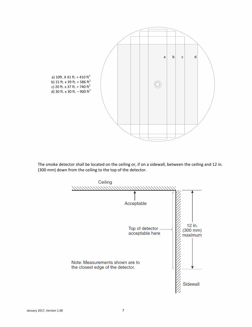
The coverage of the smoke detector is any square laid out within the confines of a circle that is 0.7 times
the listed spacing. Due to this fact, additional coverage applications can be applied. For example:
If one dimension of the coverage area is decreased the other dimension may be increased. This is shown
in the illustration below. A single smoke detector can cover any area that fits within the circle. Item “a”
illustrates a hallway that is 10 feet x 41 feet. The length of the hallway fits within the circle, and can
therefore be allowed for prescriptive system design. The coverage area is actually less than a 30’ x 30’
area. Such applications of the “0.7” rule can assist with the design of smoke detector placement in
irregularly-shaped areas.
January 2017, Version 1.00 7
a) 10ft. X 41 ft. = 410 ft2
b) 15 ft. x 39 ft. = 586 ft2
c) 20 ft. x 37 ft. = 740 ft2
d) 30 ft. x 30 ft. – 900 ft2
a b c d
The smoke detector shall be located on the ceiling or, if on a sidewall, between the ceiling and 12 in. (300 mm) down from the ceiling to the top of the detector.

January 2017, Version 1.00 8
High Ceilings
As stated above, in order for a smoke detector to detect the presence of smoke, the smoke must travel
from the point of origin to the detector, which is usually installed near the top of the space. In locations
with high ceilings (greater than 10 feet / 3 meters), it is nearly impossible to guess how the smoke will
move. This calls for a performance-based design rather than a prescriptive design.
Smoke stratification occurs when air containing smoke particles or gaseous combustion products rises
until it reaches a level at which there is no longer a difference in temperature between it and the
surrounding air. At this point the smoke will level out into a layer, as illustrated below.
Other things should be considered when high ceilings are involved; for example, what are the airflow
characteristics in the space, what are the potential fire growth rates, will the temperature in the space
change at different times of the year possibly affecting smoke movement, and so on.
To ensure rapid response where stratification may occur, it might be necessary to install smoke detectors
on sidewalls or at locations below the ceiling. In other cases, it may be determined that different smoke
detection technologies should be used (see NFPA 72 A17.7.3.2). For high ceilings or non-typical
applications, the guidelines in Annex B of NFPA 72® may be used.1
In summary, when designing for areas that have high ceilings, there is no prescriptive approach that can
ensure proper system performance. An engineering evaluation must be made; this will help to
determine how the system should be designed to achieve the performance objectives. (See NFPA 72®,
section 17.3)
1 The scope of Annex B states that it “includes a procedure for determining detector spacing based on the objectives set for the
system, size, and rate of growth of fire to be detected, various ceiling heights, ambient temperatures, and response characteristics of
the detectors.” See NFPA 72® Annex B for additional details.
If the smoke detectors
are installed on the
ceiling, how can they
detect this fire?

January 2017, Version 1.00 9
Beams and Joists on Ceilings
For ceilings with beam depths of less than 10 percent of the ceiling height (0.1 H), smooth ceiling spacing shall be permitted for spot-type smoke detectors.
Beams less than 10% of ceiling height = smooth ceiling spacing
Beam / Joist Ceiling
The detectors shall be permitted to be located on ceilings or on the bottom of beams.
For ceilings with beam depths equal to or greater than 10 percent of the ceiling height (0.1 H), the following shall apply:
Where beam spacing is equal to or greater than 40 percent of the ceiling height (0.4 H), spot-type detectors shall be located on the ceiling in each beam pocket.
Beams greater than 10% of ceiling height and beam spacing greater than 40% of ceiling height = one sensor installed in each beam pocket
Beam / Joist Ceiling
Detector / Sensor
Where beam spacing is less than 40 percent of the ceiling height (0.4 H), the following shall be permitted for spot detectors:
1. Smooth ceiling spacing in the direction parallel to the beams and at one-half smooth ceiling
spacing in the direction perpendicular to the beams
2. Location of detectors either on the ceiling or on the bottom of the beams

January 2017, Version 1.00 10
Smooth ceiling spacing parallel to the beams...
Beam / Joist Ceiling
...one-half smooth ceiling spacing perpendicular to the beams
½ S
¼ S
S
S
½ S
¼ S
½ S
½ S
½ S
½ S
S
S
½ S
½ S
½ S
½ S
½ S
S
S
½ S
½ S
½ S
½ S
½ S
S
S
½ S
½ S
½ S
½ S
½ S
S
S
½ S
S = Spacing
For other beam ceiling applications including sloping ceilings with beams/joists, please see Chapter 17 of NFPA 72®.

January 2017, Version 1.00 11
Peaked and Shed Ceilings
A Shed Ceiling is defined as a ceiling in which the high point is at one side with the slope extending toward the opposite side.
Example of a Shed Ceiling
A Peak Ceiling is defined as a ceiling in which the ceiling slopes in two directions from the highest point.
Example of a Peak Ceiling

January 2017, Version 1.00 12
For peaked ceilings, smoke detectors shall first be spaced and located within 36 in. (910 mm) of the peak,
measured horizontally.
The number and spacing of additional detectors, if any, shall be based on the horizontal projection of the ceiling. For shed ceilings, smoke detectors / detectors shall first be spaced and located within 36 in. (910 mm) of the high side of the ceiling, measured horizontally.
The number and spacing of additional detectors, if any, shall be based on the horizontal projection of the ceiling.

January 2017, Version 1.00 13
High Air Movement Areas
When installing smoke detectors in high air movement areas, the following NFPA 72® requirements apply:
Smoke detector spacing shall be reduced where the airflow in a defined space exceeds 8 minutes per air change (total space volume) (equal to 7.5 air changes per hour).
Where spacing must be adjusted for airflow, spot-type smoke detector spacing shall be adjusted in accordance with Table 17.7.6.3.3.2 or Figure 17.7.6.3.3.2 before making any other spacing adjustments required by the Code.

January 2017, Version 1.00 14
Heat Detectors
Heat detectors are primarily intended for property protection. It is not a life-safety device.
The distance between heat detectors on smooth ceilings shall not exceed the UL listed maximum
spacing or all points on the ceiling shall have a detector within a distance equal to or less than 0.7 times
the listed spacing. Heat detectors shall be located within a distance of one-half the listed spacing,
measured at right angles from all walls or partitions extending upward to within the top 15 percent of
the ceiling height.
For irregularly shaped areas, the spacing between detectors shall be permitted to be greater than the
listed spacing, provided that the maximum spacing from a detector to the farthest point of a sidewall
or corner within its zone of protection is not greater than 0.7 times the listed spacing. To illustrate:

January 2017, Version 1.00 15
49 feet (70 feet x 0.7)
The coverage of a heat detector is any square laid out within the confines of a circle that is 0.7 times
the listed spacing. As an example:
a) 15ft. X 96 ft. = 1,440 ft2
b) 30 ft. x 88.5 ft. = 2,655 ft2
c) 45 ft. x 81 ft. = 3,645 ft2
d) 70 ft. x 70 ft. – 4,900 ft2
a b c d

January 2017, Version 1.00 16
When installed on the ceiling, heat detectors must be located a minimum of 4 in. from side walls.
When installed on side walls the detector must be between 4 in. and 12 in. from the ceiling.
High Ceilings
On ceilings 10 ft. to 30 ft. (3.0m to 9.1m) high, heat detector spacing shall be reduced in accordance
with the table below prior to any additional reductions for beams, joists, or slope, where applicable.
January 2017, Version 1.00 17
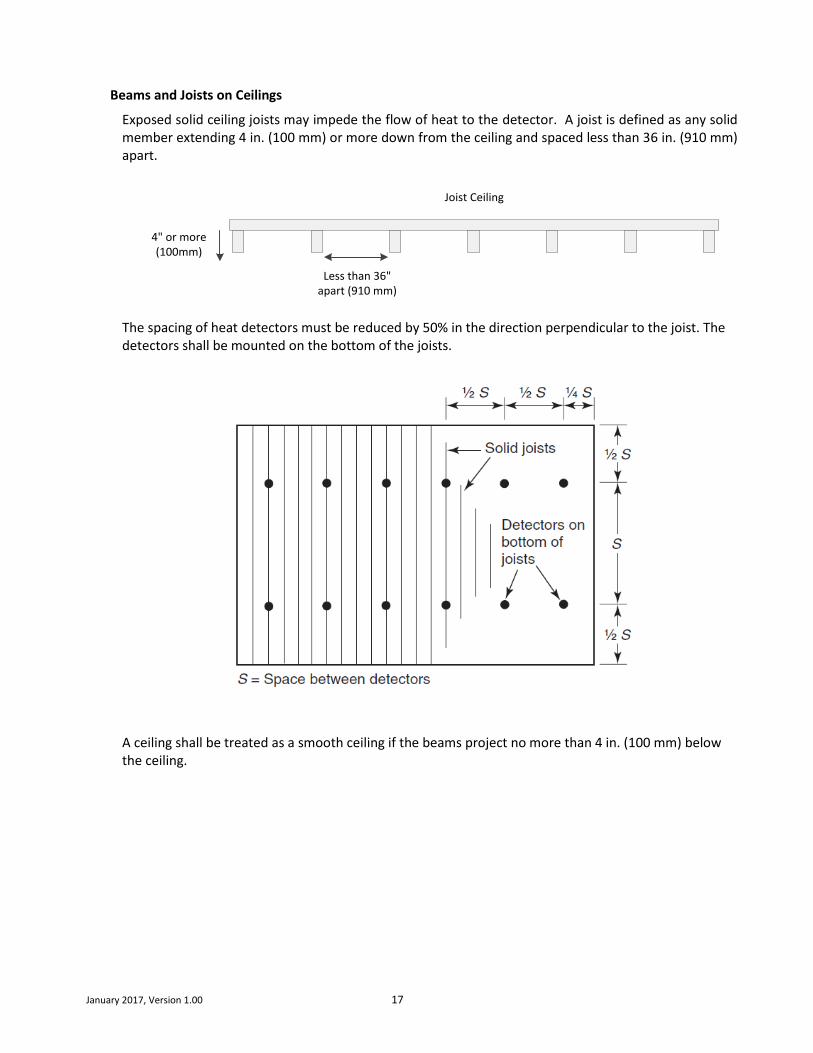
Beams and Joists on Ceilings
Exposed solid ceiling joists may impede the flow of heat to the detector. A joist is defined as any solid member extending 4 in. (100 mm) or more down from the ceiling and spaced less than 36 in. (910 mm) apart.
4" or more (100mm)
Less than 36" apart (910 mm)
Joist Ceiling
The spacing of heat detectors must be reduced by 50% in the direction perpendicular to the joist. The detectors shall be mounted on the bottom of the joists.
A ceiling shall be treated as a smooth ceiling if the beams project no more than 4 in. (100 mm) below the ceiling.

January 2017, Version 1.00 18
Beam construction is defined as ceilings that have solid structural or solid nonstructural members
projecting down from the ceiling surface more than 4 in. (100 mm) and spaced more than 36 in. (910
mm), center to center.
4" or more (100mm)
More than 36" apart (910 mm)
Beam Ceiling
Where the beams project more than 4 in. (100 mm) below the ceiling, the spacing of the heat detector
at right angles to the direction of beam travel shall be not more than two-thirds of the listed spacing.
Where beams are less than 12 in. (300 mm) in depth and less than 8 ft. (2.4 m) on center, heat detectors
shall be permitted to be installed on the bottom of beams.
Where the beams project more than 18 in. (460 mm) below the ceiling and are more than 8 ft. (2.4 m)
on center, each bay formed by the beams shall be treated as a separate area.
Annex A of NFPA 72® contains the following additional information:
The location and spacing of heat detectors should consider beam depth, ceiling height, beam spacing, and
fire size.
If the ratio of beam depth (D) to ceiling height (H), (D/H), is greater than 0.10 and the ratio of beam spacing
(W) to ceiling height (H), (W/H), is greater than 0.40, heat detectors should be located in each beam pocket.
If either the ratio of beam depth to ceiling height (D/H) is less than 0.10 or the ratio of beam spacing to
ceiling height (W/H) is less than 0.40, heat detectors should be installed on the bottom of the beams.

January 2017, Version 1.00 19
Sloping Ceilings (Peaked and Shed)
For a ceiling slope of less than 30 degrees, all detectors shall be spaced using the height at the peak.
For a ceiling slope of 30 degrees or greater, all detectors other than those in the peak shall be spaced
using the average slope height or the height of the peak.
A row of detectors shall first be located at or within 36 in. (910 mm) of the peak of the ceiling.

January 2017, Version 1.00 20
Placement of Detectors for CO Protection
Carbon Monoxide (CO) is an odorless, tasteless, highly toxic gas that results from the incomplete
combustion of fossil fuels. Hundreds of people die each year in the United States from CO poisoning.
Where should CO detectors be located in a room? NFPA provides the following requirements:
5.8.5.3 Requirements for Carbon Monoxide Detectors.2
5.8.5.3.1 Carbon monoxide detectors shall be installed as specified in the manufacturer’s published instructions
in accordance with 5.8.5.3.1(1) and 5.8.5.3.1(2), or 5.8.5.3.1(3):
(1)*On the ceiling in the same room as permanently installed fuel-burning appliances
(2) Centrally located on every habitable level and in every HVAC zone of the building
(3) A performance-based design in accordance with 5.8.5.3.2
9.4.1* Carbon Monoxide Alarms and Detectors. The warning functions intended in this standard shall be performed by
single- or multiple-station alarms or by detectors connected to a control unit and associated equipment, in accordance with
9.3.3.
9.4.1.1* Carbon monoxide alarms or detectors shall be installed as follows:
(1) Outside of each separate dwelling unit sleeping area in the immediate vicinity of the bedrooms
(2) On every occupiable level of a dwelling unit, including basements, excluding attics and crawl spaces
(3) Other locations where required by applicable laws, codes, or standards
9.4.1.2* Each alarm or detector shall be located on the wall, ceiling, or other location as specified in the manufacturer’s
published instructions that accompany the unit.
Carbon monoxide has a density similar to air, but it typically rises from the point of production due to
the heat of the combustion. As it cools to ambient temperature it circulates in the same manner as
environmental air. Eventually the air in the room will have a consistent mixture of CO throughout.
If a CO multi-criteria detector is being used for fire detection you must follow NFPA 72 location and
installation rules for smoke detectors with 30 foot spacing. It is also recommended that you confirm if
any local mounting requirements for CO detectors exist. In the absence of any specific local
requirements, the detector can be located and installed as per NFPA 72 requirements for smoke
detectors. In all cases, consult with your AHJ for proper application and design.
2 From NFPA 720, 2015 Edition. Copyright© 2014 by the National Fire Protection Association.

January 2017, Version 1.00 21
Please see the applicable Hochiki Technical Bulletin for additional details about Hochiki detectors, including
compatible bases, specifications, cleaning, and testing procedures. Technical bulletins can be obtained at
www.hochiki.com.

January 2017, Version 1.00 22
7051 Village Drive, Suite 100
Buena Park, CA 90621-2268
United States of America
1 (714) 522-2246
www.hochiki.com