Embed Size (px)
Citation preview
Technology Transfer“Hole Cleaning in Directional Wells”
Page 1
❶ Welcome to this presentation about Hole Cleaning in Directional Wells. It has been prepared by Sedco Forex, to give you a better understanding of the cuttings-transport phenomenon and how it affects drilling operations, specifically hole cleaning. All the recommendations presented here should be applied within operational needs.
❷ Why do we want to disseminate this knowledge? Because great amounts of money and time are spent, worldwide, every year combating stuck-pipe problems. In the majority of the cases, the factors that caused these problems —including hole cleaning— could have been avoided or controlled.
❸ It is very important to remember that poor hole cleaning, if not addressed properly, could eventually cause stuck pipe and other major problems, making the entire drilling operation uneconomical.
❹ By the end of this presentation you should have a good idea about how to minimize hole-cleaning problems in directional wells.
NEXT SLIDE
SFM-HC-951
HOLE CLEANING IN DIRECTIONAL WELLS
Technology Transfer“Hole Cleaning in Directional Wells”
Page 2
❶ One of the main functions performed by any drilling fluid is the removal of cuttings from the bottom of the hole and their effective transport to the surface.
❷ If this function is not performed efficiently, cuttings generated through the drilling process will begin to accumulate in the annulus. In directional wells, this problem is accentuated by gravitational forces.
❸ When not circulating, it is equally important that the drilling fluid be able to suspend the cuttings. It is here where Gel Strength and Yield Point become critical. For more information about this topic please see Appendix 1.
NEXT SLIDE
SFM-HC-952
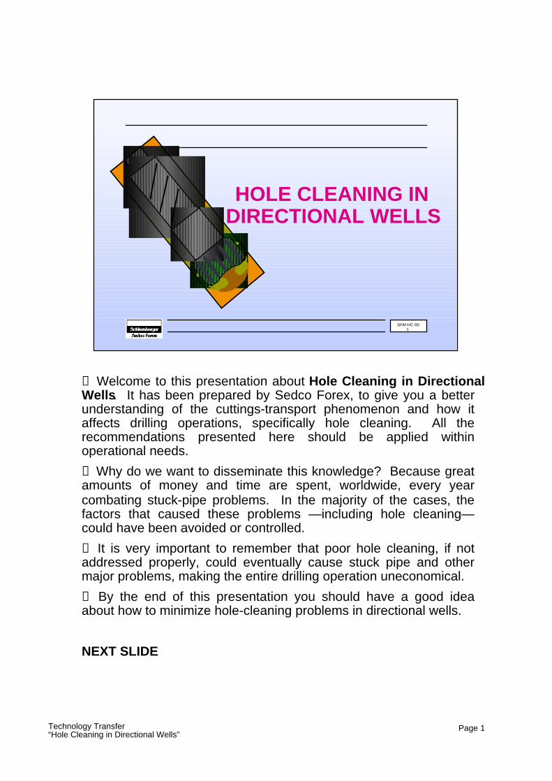
Introduction
● Drilling Fluids● Cuttings Accumulation
● Suspension Properties
Technology Transfer“Hole Cleaning in Directional Wells”
Page 3
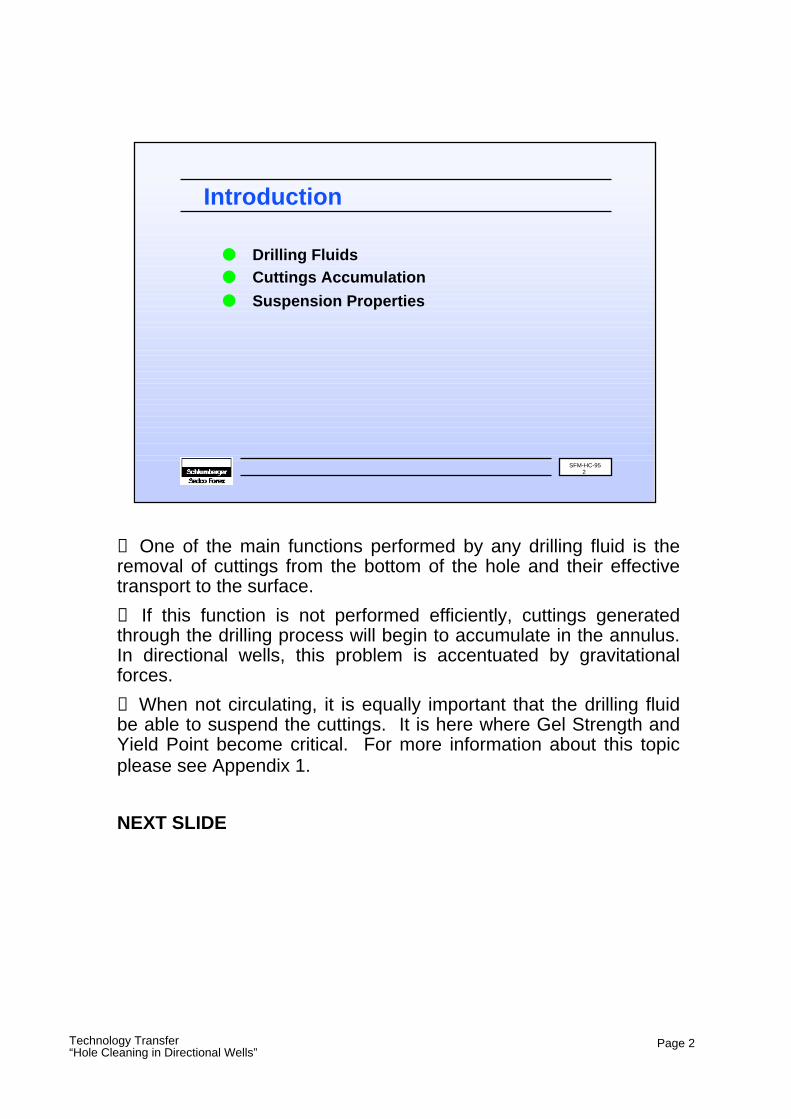
❶ During drilling, the velocity of the drilling fluid must exert a force high enough to counteract the effects of gravity, which will tend to make the cutting drop to the bottom of the well. Usually, enough velocity is achieved by the drilling fluid to perform this task efficiently in vertical wells.
❷ On the other hand, directional wells pose a more difficult problem. Influenced by gravity, the cutting will still try to drop, but due to the inclination of the well it does not have to travel too far before it reaches the lower side of the wellbore. In this situation, the velocity of the drilling fluid has to be higher in order to keep the cutting moving up towards the surface.
NEXT SLIDE
SFM-HC-953
Particle Movement
Mud Velocity
Mud Velocity
Particle Velocity
Particle Velocity
Vertical Well Directional Well
Technology Transfer“Hole Cleaning in Directional Wells”
Page 4
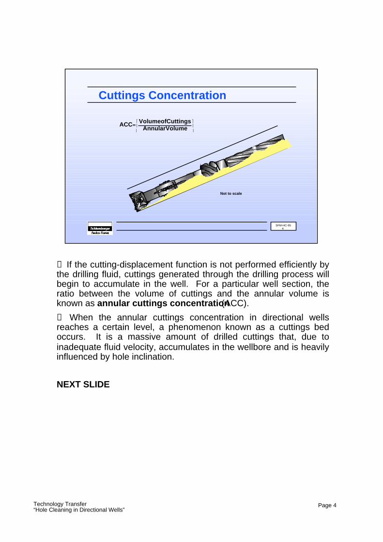
❶ If the cutting-displacement function is not performed efficiently by the drilling fluid, cuttings generated through the drilling process will begin to accumulate in the well. For a particular well section, the ratio between the volume of cuttings and the annular volume is known as annular cuttings concentration (ACC).
❷ When the annular cuttings concentration in directional wells reaches a certain level, a phenomenon known as a cuttings bed occurs. It is a massive amount of drilled cuttings that, due to inadequate fluid velocity, accumulates in the wellbore and is heavily influenced by hole inclination.
NEXT SLIDE
SFM-HC-954
Cuttings Concentration
ACC VolumeofCuttingsAnnularVolume
Not to scale
Technology Transfer“Hole Cleaning in Directional Wells”
Page 5
❶ Experience shows that high annular cuttings concentration —in the form of cuttings beds— is the main factor that causes severe hole problems like:
High torque & drag (manifested as lack of tool-face control/steering, and poor weight transfer), stuck pipe (costly and time consuming), and difficulty when running/cementing casing.
Therefore, it should be carefully considered regarding hole cleaning in directional wells.
❷ Numerous studies have shown that to limit the formation of a cuttings bed, the annular mud velocity in directional wells has to be significantly higher than in vertical wells.
NEXT SLIDE
SFM-HC-955
Cuttings Beds
● Poor hole cleaning may cause:➥ High Torque and Drag
➥ Stuck Pipe➥ Casing Problems
● Vmud (directional) > Vmud (vertical)
Technology Transfer“Hole Cleaning in Directional Wells”
Page 6
Let’s take a look at the more important factors that affect hole cleaning. They are:
❶ Flow Rate
❷ Flow Type (laminar/turbulent)
❸ Wellbore Inclination
❹ Fluid Rheology & Density
❺ Rate of Penetration
In addition, other parameters like Particle Settling Velocity, Particle Geometry and Distribution, Drillpipe Eccentricity, and Drillpipe Rotation also influence hole cleaning.
NEXT SLIDE
SFM-HC-956
Cuttings Transport
● Flow Rate (annular velocity)● Flow Type (laminar/turbulent)
● Wellbore Inclination● Fluid Rheology● Rate of Penetration

Technology Transfer“Hole Cleaning in Directional Wells”
Page 7
For the purpose of hole cleaning efficiency, all well sections can be categorized into three main types (according to their degree of inclination) :
❶ Type I, includes the vertical (0° - 10°), and low-inclination well sections (10° - 40°).
❷ Type II, includes well sections with an inclination between 40 and 60 degrees.
❸ Type III, includes well sections with inclinations over 60 degrees.
NEXT SLIDE
SFM-HC-957
Types of Wellbores
● Type I —> (0° to 40°)● Type II —> (40° to 60°)
● Type III —> (over 60°)
Technology Transfer“Hole Cleaning in Directional Wells”
Page 8
❶ Full-scale experiments have shown that in wellbores with a 10° inclination, movement and concentration of cuttings is only slightly worse than in vertical wells. Therefore, inadvertent hole deviations up to ten degrees, in vertical-hole drilling, should not pose any special hole-cleaning problems.
❷ It has also been found that, in vertical sections, high-viscosity muds provide better cuttings transport than low-viscosity muds.
❸ In addition, pipe-rotation effects are minor (specially in turbulent flow).
❹ Finally, cuttings transport in vertical sections is nearly the same for all drillpipe eccentricities.
NEXT SLIDE
SFM-HC-958
Type I — Vertical Section (0°- 10°)
● Hole Cleaning● Fluid Viscosity
● Pipe Rotation● Drillpipe Eccentricity
Technology Transfer“Hole Cleaning in Directional Wells”
Page 9
❶ Compared to vertical sections, low-angle well sections require higher annular velocities in order to achieve effective hole cleaning.
❷ Because of increasing inclination, more and more cuttings are forced toward the low side of the annulus, where they slide downward and are eventually lifted and re-enter the high-velocity region at the middle of the annulus. After this, they are swept upward, and the process is repeated. This phenomenon is described as “particle recycling”, and has a detrimental effect on hole cleaning.
❸ Also, it can be said that for this type of well section, the effect of laminar flow dominates cuttings transport. Therefore, viscosity, yield point, and initial gel strengths have a significant effect on annular cuttings concentration and hole cleaning efficiency.
NEXT SLIDE
SFM-HC-959
Type I — Low-Angle Sections (10°- 40°)
● Annular Velocity● Particle Recycling
● Laminar Flow
Technology Transfer“Hole Cleaning in Directional Wells”
Page 10
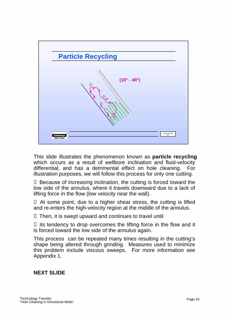
This slide illustrates the phenomenon known as particle recycling, which occurs as a result of wellbore inclination and fluid-velocity differential, and has a detrimental effect on hole cleaning. For illustration purposes, we will follow this process for only one cutting.
❶ Because of increasing inclination, the cutting is forced toward the low side of the annulus, where it travels downward due to a lack of lifting force in the flow (low velocity near the wall).
❷ At some point, due to a higher shear stress, the cutting is lifted and re-enters the high-velocity region at the middle of the annulus.
❸ Then, it is swept upward and continues to travel until
❹ its tendency to drop overcomes the lifting force in the flow and it is forced toward the low side of the annulus again.
This process can be repeated many times resulting in the cutting’s shape being altered through grinding. Measures used to minimize this problem include viscous sweeps. For more information see Appendix 1.
NEXT SLIDE
SFM-HC-9510
Particle Recycling
(10° - 40°)
1
3
2
4
Technology Transfer“Hole Cleaning in Directional Wells”
Page 11
❶ In well sections with inclinations greater than 40 degrees, cuttings do not recycle as readily as in lower-angle sections. This is because gravity tends to hold them down on the low side of the hole.
❷ Well sections with inclinations between 40° and 60° are considered critical, not only because a cuttings bed develops, but because it is unstable and prone to sliding downward (avalanching). The consequence of avalanching is an instantaneous build-up of cuttings around the drillpipe and/or BHA which, if not treated properly, can result in stuck pipe.
❸ Turbulent flow exhibits a desirable, eroding effect on cuttings beds.
❹ Pipe movement (rotation/reciprocation) mechanically disturbs cuttings beds.
NEXT SLIDE
SFM-HC-9511
Type II — Crit.-Angle Sections (40°- 60°)
● Cuttings Behavior● Cuttings Beds
● Annular Velocity● Pipe Movement
Technology Transfer“Hole Cleaning in Directional Wells”
Page 12
❶ At high angles of inclination the formation of a cuttings bed is almost instantaneous, and its thickness is governed primarily by annular velocity.
❷ The cuttings bed that forms at angles greater than 60 degrees is stable, this means it will not avalanche.
❸ The waving, vortex-like, character of turbulent flow has a destructive influence on the bed being formed. There is a tendency for cuttings to be withdrawn (lifted) from the bed and displaced upwards in the annulus, where such a process may occur again. This kind of interaction, together with the flat velocity-profile typical of turbulent flow, leads to better hole cleaning.
❹ Pipe movement (rotation/reciprocation) mechanically disturbs cuttings beds.
NEXT SLIDE
SFM-HC-9512
Type III — High-Angle Sections (60°+)
● Instantaneous Bed Formation● Stationary Cuttings Bed
● Turbulent Flow● Pipe Movement
Technology Transfer“Hole Cleaning in Directional Wells”
Page 13
The following are some field guidelines that Sedco Forex recommends for effective hole cleaning in low-angle well sections:
❶ General use of laminar flow.
❷ Maintaining a high Yield Point and Gel Strength to reduce the settling of cuttings when pumps are off. Always ensuring that the hole is clean before turning the pumps off.
❸ Maximizing YP/PV ratio.
❹ Using viscous sweeps to reduce the effects of particle recycling.
NEXT SLIDE
SFM-HC-9513
Field Guidelines
Type I Well Sections (0° - 40°)● Laminar Flow
● High Yield Point/ Gel Strength● Maximize YP/PV● Use Viscous Sweeps
Technology Transfer“Hole Cleaning in Directional Wells”
Page 14
In the well sections over 40 degrees, attention must focus on minimizing cuttings beds.
❶ For the range of intermediate inclinations (40° - 60°), turbulent flow is recommended. Since cuttings transport in turbulent flow is not affected by rheological properties, lower mud parameters (i.e. YP, PV) may be used. However, static mud parameters such as gel strength are usually desirable even if turbulent flow is preferable. If turbulent flow cannot be used because of other adverse factors, like wellbore instability, annular velocity should be kept as high as possible.
❷ Rotating and/or reciprocating drillpipe has a mechanical, destructive influence on the cuttings bed (this influence is the main factor that provides a higher cleaning rate for higher RPM). As pipe rotation is typically governed by directional-drilling needs, periodic wiper trips should be considered.
❸ Combination sweeps (low viscosity/high density) are effective at eroding the cuttings bed, and carrying the cuttings to surface.
NEXT SLIDE
SFM-HC-9514
Field Guidelines (cont.)
Type II Well Sections (40° - 60°)● Turbulent Flow
● Mechanical Agitation● Combination Sweeps
Technology Transfer“Hole Cleaning in Directional Wells”
Page 15
❶ Turbulent flow is preferable in high-angle wells. Generally, the same recommendations as those described for intermediate-angle wells are applicable in this region for turbulent flow; however, the requirements to ensure a mud gel strength are less important. If turbulent flow cannot be achieved, the YP/PV ratio should be maintained as high as possible.
❷ Again, rotating and/or reciprocating drillpipe has a mechanical, destructive influence on the cuttings bed. It is this influence that provides a higher cleaning rate for higher RPM, particularly at high inclinations where a considerable cuttings bed is formed. Periodic wiper trips should be used if drillpipe rotation is restricted.
❸ Combination sweeps (low viscosity/high density) are effective at eroding the cuttings bed, and carrying the cuttings to surface. The effectiveness of a cuttings-bed-maintenance program can be determined through several indicators.
NEXT SLIDE
SFM-HC-9515
Field Guidelines (cont.)
Type III Well Sections (60° +)● Turbulent Flow
● Mechanical Agitation● Combination Sweeps
Technology Transfer“Hole Cleaning in Directional Wells”
Page 16
The following are some effective indicators of poor hole cleaning:
❶ Abnormally low or intermittent cuttings volume discharge.
❷ High pick-up weight.
❸ Poor weight transfer. A higher than normal surface weight (slack-off) is required to get a pressure-drop response from the mud motor.
❹ Difficulty orienting the motor, due to excessive friction between the cuttings and the drillstring.
❺ Excessively ground cuttings, due to extended particle recycling and drillpipe interaction with the cuttings bed.
NEXT SLIDE
SFM-HC-9516
Field Guidelines (cont.)
Poor-Hole-Cleaning Indicators● Reduced Cuttings Return
● High Pick-Up Weight● Poor Weight Transfer● Difficulty Orienting Motor
● Excessive Grinding of Cuttings
Technology Transfer“Hole Cleaning in Directional Wells”
Page 17
Let’s take a look at a recent drilling program implemented by a major operator in the UK.
❶ This was an extended-reach drilling program comprised of several wells with an average total depth of 23000 ft (7012 m), and a horizontal departure of 19500 ft (5945 m). Departure-to-depth ratio of 4:1.
❷ Hole cleaning was identified as a critical factor in the success of this project.
❸ The entire hydraulics program was designed to achieve maximum annular velocity. Flow rates up to 1150 gpm were used, in conjunction with 65/8” drillpipe, generating annular velocities up to 264 ft/min, and standpipe pressures up to 4500 psi. No hole-cleaning problems were experienced in either the 121/4” or 81/2” sections.
NEXT SLIDE
SFM-HC-9517
An Operator’s Experience (1995)
● Extended-Reach Wells➥ Total Depth of 23000 ft
➥ Horiz. Departure of 19500 ft
● Hole Cleaning Challenge
● High Annular Velocity➥ Flow Rate @ 1150 gpm (264 ft/min)➥ 65/8” Drillpipe (SPP 4500 psi)
Technology Transfer“Hole Cleaning in Directional Wells”
Page 18
❶ In order to achieve the mentioned operational parameters, significant equipment modifications were required. To meet flow-rate demands three 1600 HP pumps were installed (together with adequate power systems), and larger 65/8” drillpipe was used. This helped lower frictional pressure losses (inside the pipe) and increase annular velocity. As part of this process, surface lines where also refitted to meet the high-pressure demands.
❷ All these modifications had a significant cost; however, the performance incentives offered by the operator to the drilling contractor made this a profitable venture. We must remember that by ensuring adequate hole cleaning the risk of stuck pipe and other costly events is diminished —this enabled the drilling contractor to finish most of these challenging wells ahead of schedule.
NEXT SLIDE
SFM-HC-9518
An Operator’s Experience (cont.)
● Equipment Requirements➥ Three 1600 HP pumps
➥ High HP power systems➥ Larger 65/8” drillpipe
➥ Larger surface lines
● Financial Considerations➥ Cost
➥ Profit
Technology Transfer“Hole Cleaning in Directional Wells”
Page 19
Let’s summarize the key points from this presentation:
❶ High annular velocity equals improved hole cleaning. This applies to any wellbore inclination.
❷ Whether or not cuttings beds are stable is determined by the well-section angle; however, anytime well inclination surpasses 40° expect a cuttings bed to form.
❸ Turbulent flow erodes cuttings beds.
❹ Mechanical agitation (pipe rotation/reciprocation) reduces bed thickness.
NEXT SLIDE
SFM-HC-9519
Summary
● High annular velocity equals improved hole cleaning
● Cuttings beds form at any angle over 40 degrees
● Turbulent flow erodes cuttings beds● Drillpipe rotation and/or reciprocation aids in
cuttings bed maintenance
Technology Transfer“Hole Cleaning in Directional Wells”
Page 20
❶ In laminar flow, carrying capacity is affected by rheology. Therefore, increasing the ratio of yield point to plastic viscosity (YP/PV) increases the carrying capacity of a drilling fluid. This becomes important when turbulent flow cannot be achieved.
❷ In turbulent flow, carrying capacity is not affected by rheology.
❸ Combination sweeps (low viscosity/high density) are effective in removing cuttings.
NEXT SLIDE
SFM-HC-9520
Summary (cont.)
● In laminar flow, cuttings transport is affected by rheology
● In turbulent flow, cuttings transport is not affected by rheology
● Combination sweeps are effective in hole cleaning
Technology Transfer“Hole Cleaning in Directional Wells”
Page 21
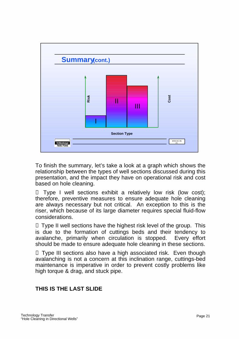
To finish the summary, let’s take a look at a graph which shows the relationship between the types of well sections discussed during this presentation, and the impact they have on operational risk and cost based on hole cleaning.
❶ Type I well sections exhibit a relatively low risk (low cost); therefore, preventive measures to ensure adequate hole cleaning are always necessary but not critical. An exception to this is the riser, which because of its large diameter requires special fluid-flow considerations.
❷ Type II well sections have the highest risk level of the group. This is due to the formation of cuttings beds and their tendency to avalanche, primarily when circulation is stopped. Every effort should be made to ensure adequate hole cleaning in these sections.
❸ Type III sections also have a high associated risk. Even though avalanching is not a concern at this inclination range, cuttings-bed maintenance is imperative in order to prevent costly problems like high torque & drag, and stuck pipe.
THIS IS THE LAST SLIDE
SFM-HC-9521
Summary (cont.)
III
I
II
Section Type
Ris
k
Co
st
Technology Transfer“Hole Cleaning in Directional Wells”
Page 22
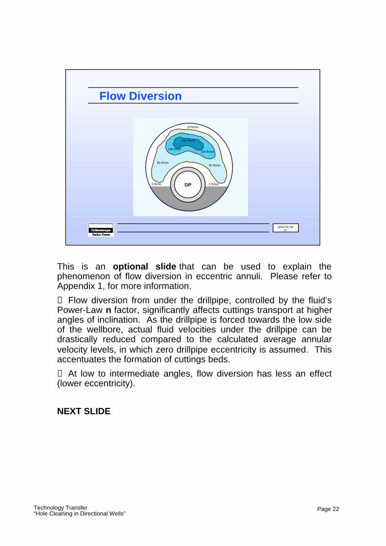
This is an optional slide that can be used to explain the phenomenon of flow diversion in eccentric annuli. Please refer to Appendix 1, for more information.
❶ Flow diversion from under the drillpipe, controlled by the fluid’s Power-Law n factor, significantly affects cuttings transport at higher angles of inclination. As the drillpipe is forced towards the low side of the wellbore, actual fluid velocities under the drillpipe can be drastically reduced compared to the calculated average annular velocity levels, in which zero drillpipe eccentricity is assumed. This accentuates the formation of cuttings beds.
❷ At low to intermediate angles, flow diversion has less an effect (lower eccentricity).
NEXT SLIDE
SFM-HC-9522
Flow Diversion
DP
150 ft/min
60 ft/min
100 ft/min100 ft/min
60 ft/min
10 ft/min
5 ft/min 5 ft/min
Technology Transfer“Hole Cleaning in Directional Wells”
Page 23
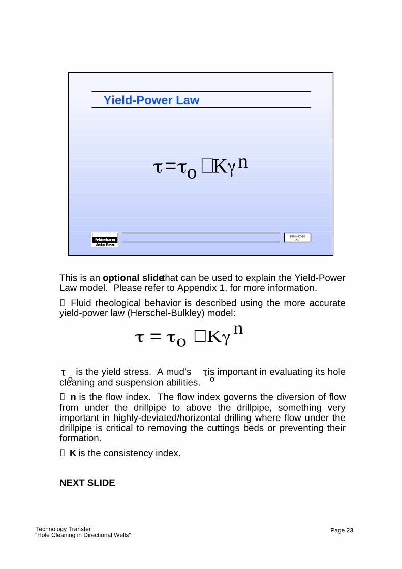
This is an optional slide that can be used to explain the Yield-Power Law model. Please refer to Appendix 1, for more information.
❶ Fluid rheological behavior is described using the more accurate yield-power law (Herschel-Bulkley) model:
is the yield stress. A mud’s is important in evaluating its hole cleaning and suspension abilities.
❷ n is the flow index. The flow index governs the diversion of flow from under the drillpipe to above the drillpipe, something very important in highly-deviated/horizontal drilling where flow under the drillpipe is critical to removing the cuttings beds or preventing their formation.
❸ K is the consistency index.
NEXT SLIDE
SFM-HC-9523
Yield-Power Law
= o +K n
= o + K n
τo
τo
Technology Transfer“Hole Cleaning in Directional Wells”
Page 24
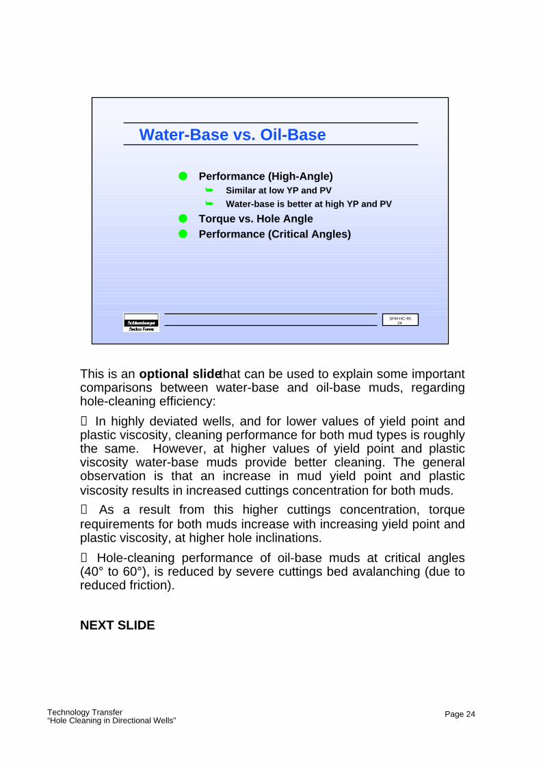
This is an optional slide that can be used to explain some important comparisons between water-base and oil-base muds, regarding hole-cleaning efficiency:
❶ In highly deviated wells, and for lower values of yield point and plastic viscosity, cleaning performance for both mud types is roughly the same. However, at higher values of yield point and plastic viscosity water-base muds provide better cleaning. The general observation is that an increase in mud yield point and plastic viscosity results in increased cuttings concentration for both muds.
❷ As a result from this higher cuttings concentration, torque requirements for both muds increase with increasing yield point and plastic viscosity, at higher hole inclinations.
❸ Hole-cleaning performance of oil-base muds at critical angles (40° to 60°), is reduced by severe cuttings bed avalanching (due to reduced friction).
NEXT SLIDE
SFM-HC-9524
Water-Base vs. Oil-Base
● Performance (High-Angle)➥ Similar at low YP and PV
➥ Water-base is better at high YP and PV
● Torque vs. Hole Angle● Performance (Critical Angles)