Embed Size (px)
Citation preview

Brief Summary
Item No. 11.6
2x500 MW Chandrapur Super Thermal Power Project Expansion Project at Chandrapur, District
Chandrapur, Maharashtra by M/s Maharashtra State Power Generation Company Limited - reg.
Amendment in Environment Clearance. File No: J-13011/53/2008-IAII(T) & Online no:
IA/MH/THE/10241/2008.
Maharashtra State Power Generation Company Limited proposed to amend the transportation mode of
raw coal from Bhatadi and Padmapur OC mines of WCL. Presently the coal is being transported by road
by tarpaulin covered trucks/tippers. The proposed mode will be Cross Country Conveyor System from
Bhatadi and Padmapur mines to Chandrapur Thermal Power Plant. The length of new transportation
mode will be 6.431 km. The conveyor system along its entire route of 6.431 km will cross 3 nallah, 1
river, 1 major road, 2 HT lines, 14 LT lines.
The pipe conveyor system will pass through villages Padmarpur, Chak Tirwanja, Chandrsula, Mingaon,
Bhatadi.
Along its route there is no reserve forest, so flora – fauna will not be affected. As raw coal will be
sprinkled with water, so the dust pollution will be minimum and while carrying from the nallah and river
the coal will not come in direct contact with water, so water as well as Flora – Fauna will not be affected.
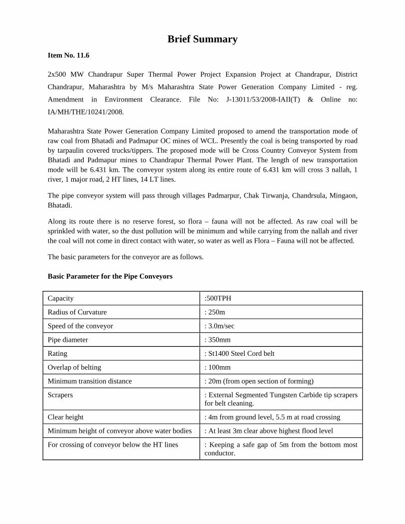
The basic parameters for the conveyor are as follows.
Basic Parameter for the Pipe Conveyors
Capacity :500TPH
Radius of Curvature : 250m
Speed of the conveyor : 3.0m/sec
Pipe diameter : 350mm
Rating : St1400 Steel Cord belt
Overlap of belting : 100mm
Minimum transition distance : 20m (from open section of forming)
Scrapers : External Segmented Tungsten Carbide tip scrapersfor belt cleaning.
Clear height : 4m from ground level, 5.5 m at road crossing
Minimum height of conveyor above water bodies : At least 3m clear above highest flood level
For crossing of conveyor below the HT lines : Keeping a safe gap of 5m from the bottom mostconductor.

For crossing of conveyor MV and LT power lines : These shall be crossed by rerouting of theconductors underground.
The cost of the project will be approx. Rs 124 Cr. In existing plant operation coal is being transported by
rail wagon from SECL & by road from various mines of WCL.

Maharashtra State Power Generation Co. Ltd.(MAHAGENCO)
<
DETAILED PROJECT REPORT:
MSPGCL Chandrapur STPS Coal Transport Scheme
PROJECT CODE: 15540
DEC 2015
HOLTEC CONSULTING PRIVATE LIMITED

DPR : DETAILED PROJECT REPORTMSPGCL Chandrapur STPS Coal Transport Scheme
CONFIDENTIAL
THIS DOCUMENT SHOULD BE TREATED AS CONFIDENTIAL AND MUST NOT BE REPRODUCED,
COPIED, LOANED OR DISPOSED, DIRECTLY OR INDIRECTLY, NOR USED FOR ANY PURPOSE OTHER
THAN FOR WHICH IT IS SPECIFICALLY FURNISHED, WITHOUT THE PRIOR WRITTEN CONSENT OF
HOLTEC CONSULTING PRIVATE LIMITED, GURGAON.
Project: 15540 CONFIDENTIAL Page 1 of 1

DPR : DETAILED PROJECT REPORTMSPGCL Chandrapur STPS Coal Transport Scheme
ACKNOWLEDGEMENT
WE EXPRESS OUR SINCERE GRATITUDE TO THE OFFICIALS OF THE MAHARASHTRA STATE POWER
GENERATION COMPANY LIMITED (MAHAGENCO) & CHANDRAPUR STPS (CSTPS) FOR THE ASSISTANCE
AND CO-OPERATION EXTENDED DURING OUR VISIT, BUT FOR WHICH THIS REPORT COULD NOT HAVE
BEEN SUCCESSFULLY PREPARED.
Project: 15540 ACKNOWLEDGEMENT Page 1 of 1

DPR : DETAILED PROJECT REPORTMSPGCL Chandrapur STPS Coal Transport Scheme
TABLE OF CONTENT
CHAPTER NO. DESCRIPTION
1. INTRODUCTION
ANNEXURE 1.1:MOM DATED 10.12.2015
2. TECHNICAL CONCEPT
ANNEXURE 2.1:PIPE CONVEYOR LAYOUT-ROUTE IAANNEXURE 2.2:SINGLE LINE DIAGRAMANNEXURE2.3: CONTROL CONFIGURATION DIAGRAM
3. COST ESTIMATES
4. OPERATION & MAINTENANCE
5. EXECUTION SCHEDULE
ANNEXURE : 5.1 EXECUTION SCHEDULEANNEXURE : 5.2 ENVIRONMENTAL IMPACT
Project 15540 TOC Page 1 of 1

CHAPTER - 1
INTRODUCTION
<
DPR : DETAILED PROJECT REPORTMSPGCL Chandrapur STPS Coal Transport Scheme
CHAPTER 1: INTRODUCTION
This chapter encapsulates the background information about the Client and purpose of thisDetailed Project Report (DPR).
1.0 PREAMBLE
Maharashtra State Power Generation Co Ltd (Mahagenco) is engaged in the business ofpower generation and has been vested with power generation assets. It has the overall highestgeneration capacity amongst all the state power generation utilities in India.
Chandrapur Super Thermal Power Station (CSTPS) is the biggest power generation unit ofMahagenco consisting of 7 operating units and 2 units under final stages of execution.
First 4 units of CSTPS are of 210 MW each, Unit 5, 6 and 7 are of 500 MW each. Unit 8 and 9 arealso of 500 MW each.
For the first 7 units of Mahagenco, coal required for power generation is being catered by coalmines nearby i.e. Durgapur, Padmapur & Bhatadi mines which are owned and operated byWestern Coal Fields.
Western Coalfields Limited (WCL) is one of the eight Subsidiary Companies of Coal IndiaLimited (CIL) which is under administrative control of Ministry of Coal. The Companyincorporated under the Companies Act, 1956 has its registered office at Nagpur.It has miningoperation spread over the states of Maharashtra (in Nagpur, Chandrapur & Yeotmal Districts)and Madhya Pradesh (in Betul and Chhindawara Districts).
The Company is a major source of supplies of coal to Mahagenco. Presently coal from Durgapurmines is conveyed through a ropeway catering primarily unit 1 to 4. A captive rail link (based onbottom discharge wagons – BOBRN wagons) is available from Padmapur mines, whereas coalfrom Bhatadi is transported through tipper trucks. Both Padmapur and Bhatadi primarily cater tounit 5, 6 and 7 of CSTPS. For Unit 8 and 9 coal shall be obtained from outside through Boxwagons and shall be unloaded through a set of wagon tipplers.
As the reserves at Padmapur mines are nearing exhaustion, unit 5, 6 and 7 are primarilydependent on Bhatadi Mines. Coal from Bhatadi is transported through dump trucks. Roadtransport has limitation of throughput, multiple handling of coal, poor reliability oftransporters/contractors, poor environmental sustainability, safety issues are some of the concernpoints for Mahagenco. Bhatadi mines are also undergoing expansion, which will further aggravatethe current issues.
To mechanize the coal handling & transportation system from Bhatadi mines to CSTPS, which isapproximately located at an aerial distance of 9 KM. Mahagenco has entrusted HoltecConsulting Pvt Ltd (HOLTEC) for consultancy services for exploration of various routing options,mode of Transportation and execution of project through EPC tendering.
2.0 CHRONOLOGY
Holtec was awarded Letter of Award (LOA) vide ref letter no 2091 dated 29.10.2015 against.Mahagenco’s tender no 18612. Kick off meeting for the project was held at Mahagenco at theHead Office on 02.11.2015 wherein communication protocol, team introduction and next stepswere firmed up.
Project 15540 CHAPTER 1: INTRODUCTION Page 1 of 3

<
DPR : DETAILED PROJECT REPORTMSPGCL Chandrapur STPS Coal Transport Scheme
Hol
tec team visited sites of Bhatadi mines, Padmapur mines, CSTPS on November 06th & 7th 2015and held detailed discussions with Mahagenco officials & Western Coal Field personnel.
Technical feasibility study report covering evaluation and recommendations for Routing optionsand mode of transportation was submitted on 27th November 2015.
Mahagenco endorsed the outcomes of the feasibility study and gave clearance on 08.12.2015 forpreparation of DPR.
Subsequently meeting was held to present technical feasibility study report and to finalizerequired inputs for DPR preparation on 10.12.2015 at Nagpur.
Mahagenco provided necessary route survey for Route IA on 28.12.2015.
The DPR for proposed scheme of transportation of coal from Bhatadi mine to ChandrapurSTPS is revised and submitted on 21.09.2017 in line the approval from MERC.
However due to constrain in obtaining private land the route is revised & length of therevised route is 6.431 km and instead of one pipe conveyor three pipe conveyor areconsidered.
3.0 Structure of the Report
This DPR covers detailed design parameters and cost estimates for the proposed projectfollowing Route IA and recommended mode of transport as Pipe Conveyor. For the understandingof back ground, this report shall be read in conjunction with TFS duly submitted and approved byMahagenco.
The report
This report has been formulated based upon the following.
• Data collected during the site visit, first hand data verification & assessment andsecondary research. This study draws extensively from HOLTEC database on plantdesign, investment costs and operating costs.
• Pipe conveyor from Bhatadi till Padampur shall follow Route IA.
• Soil investigation on route IA is yet to be taken up. In absence of the soil results, DPR isbased on soil data provided by Mahagenco, based on their experience of previousconstruction work.

<
DPR : DETAILED PROJECT REPORTMSPGCL Chandrapur STPS Coal Transport Scheme
CHAPTER 1: INTRODUCTION
TABLE OF CONTENTS
1.0 PREAMBLE _______________________________________________________1
2.0 CHRONOLOGY 1
3.0 STRUCTURE OF THE REPORT__________________________________________2
Project 15540 CHAPTER 1: INTRODUCTION Page 3 of 3

CHAPTER – 2
TECHNICAL CONCEPT

DPR : DETAILED PROJECT REPORTMSPGCL Chandrapur STPS Coal Transport Scheme
CHAPTER 2: TECHNICAL CONCEPT
1. INTRODUCTION
This Detailed Project Report (DPR) is prepared in continuance of Technical FeasibilityStudy submitted and duly approved by Mahagenco. This chapter describes the detailedengineering aspects of the selected option for conveying coal from mines for ChandrapurSTPS. As described in TFS the pipe conveyor is the most suitable conveying option for theproject.
The conveying of coal by pipe conveyor starts from Bhatadi mines and terminates at InMotion wagon loading system at Padmapur mines following Route 1A. From Padmapurmines, subsequent transport of coal shall take place by means of existing railway system ofMahagenco.
The basis of system design taken into consideration, design criteria for electromechanicalmachinery, technical specifications have been covered in this chapter.
2. EXCERPTS FROM TECHNICAL FEASIBILITY STUDY
The Technical Feasibility Study was taken up by Holtec with preliminary route surveyconducted by MNEC for Mahagenco. Three routes (Route I, II & III) were provided byMahagenco. Technical feasibility and viability was evaluated by Holtec for various options.Holtec proposed another option wherein as route IA which is slight variation of the route Iwhich was recommended. The modes of conveying were scrutinized and comparison wasdone between pipe conveyor, open curved belt conveyor and aerial ropeway. Post technicalevaluation between the three and in comparison of the same pipe conveyor wasrecommended as preferred option over other two.
The major recommendations of the technical feasibility study are presented as under:
1. Due to constrain in obtaining private land the route is revised & length of the revisedroute is 6.431 km and instead of one pipe conveyor three pipe conveyor areconsidered.
2. Taking considerations of high effect of environmental sensitivity, limited spaceavailability, handling capability of curves, safety, operational ease, cost for landacquisition, closed conveying of coal, Pipe conveyor works out to be most suitableoption.
3. Performance of transportation system is highly dependent on supply of coal suppliedby WCL at Bhatadi Mines substantial upgradation or installation of another crushingplant is essential along with general upgradation of power distribution system. Asthis portion need to be executed by WCL, a close coordination is required betweenthe management of WCL and Mahagenco.
4. The conveying system from Bhatadi shall bring the coal to Padmapur rail loadingarea, and with the installation of another in motion train load station it can workindependently of Padmapur coal supply system. This will avoid mixing of coalsupplied from the two mines avoiding logistics and commercial issues.

DPR : DETAILED PROJECT REPORTMSPGCL Chandrapur STPS Coal Transport Scheme
: 3 3KV
5. Expeditious implementation of the coal transportation system is recommended, sothat Mahagenco does not remain dependent on present road transportation andassociated hassles of road transportation through habited areas etc
3. DESIGN ASPECTS OF THE PROPOSED SYSTEM
The detailing of Pipe conveyor is being presented in this DPR along with auxiliary systemsrequired and other implied design criteria. The basis of system design, general siteconditions, capacity requirements, duty conditions, topographical survey outcomes, geo-technical considerations for proposed system have been presented as under.
3.1. PHYSICAL PROPERTIES OF MATERIAL
The major physical properties of coal to be transported are mentioned as under:
S.No. Description Unit Design value
1 Bulk density for volumetric sizing t/m3 0.8
2 Bulk density for power sizing t/m3 0.96
3 Material temperature °C Ambient
4 Angle of repose Deg. 40
5 Moisture Content % < 12 %
6 Permissible dust emission Mg/Nm3 30
7 Lump size (post crushing) mm -100
Table 2.1: Physical properties of coal
3.2. INPUTS CONSIDERATIONS FORELECTRICAL AND CONTROL DESIGN
Power Distribution
Incoming Power supply (From Grid)
Medium Voltage Distribution (MV) : 6 .6KV
MV Short circuit fault current level : 25kA/1sec for 6.6kV
Low Voltage (LV) : 433V
LV Short circuit fault current level : 50kA/1sec
Lighting Voltage : 230V
Maintenance Voltage : 415V (3 phase)
Auxiliary Control Voltage
MV & LV Switchgears : 110V DC/220V AC
MCC Control Voltage : 220V AC
Interrogation Control Voltage : 220V AC
Automation Control Voltage : 220V AC/24 VDC
DPR : DETAILED PROJECT REPORTMSPGCL Chandrapur STPS Coal Transport Scheme
3.3. INPUTS CONSIDERATIONS FOR CIVIL DESIGN
Design Wind Velocity : 47 m/s.
Seismicity : Zone III
Terrain : Flat
Water Table : at 3 m depth.
3.4. GENERAL SITE CONDITION
3.4.1. LOCATION
The location of Bhatadi mines with latitude/ longitude & distance from major places are givenbelow:
Latitude : 19.57°N
Longitude : 79.18°E
Nearest City : Chandrapur
Nearest Railway Station : Chandrapur
Nearest Airport : Nagpur
Nearest Seaport : Kakinada/Vishakapatnam
3.4.2. LOCAL CLIMATIC CONDITION
The local climatic conditions at Chandrapur are as described hereunder:
Site Level : 189.9 m Height of site above sea level
Temperature : Max. 49°C, Min. 3° C, Avg 28.2° C
Rain fall : Avg. 1250 mm/year
Humidity : Max. 88%
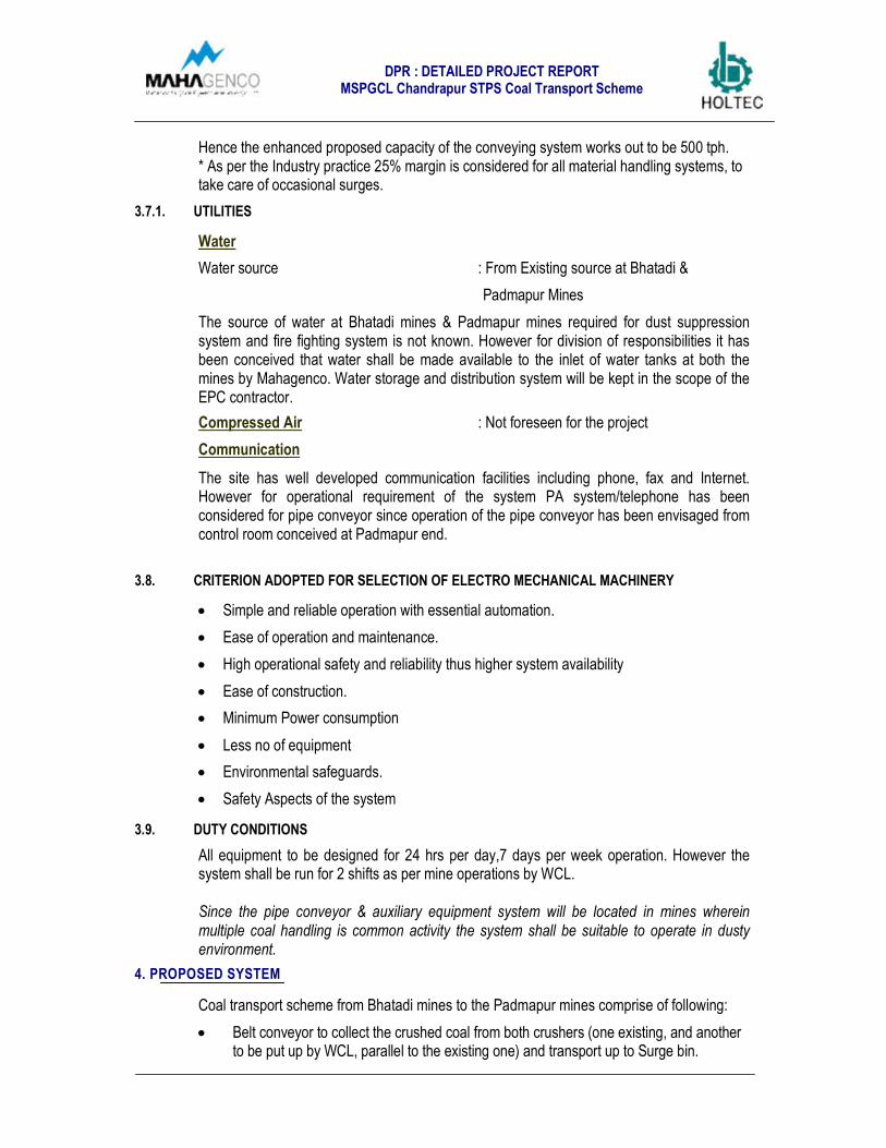
3.5. TOPOGRAPHY
The topography of the area generally forms the flat terrain fertile piece of lands encounteredoutside the mines area. Maximum relative difference in ground level observed whiletraversing Route IA is 12-14 m.
Fig 2.1 Contour levels from Bhatadi start point to Erai river is shown for reference purpose
Topographical report also reveals that several Water bodies are also observed on route 1A.
Erai river :- Erai river is passing between the Bhatadi mines and Padmapur mines and itis located approx in middle of the pipe conveyor route. Width of river is 101.49m.Highest flood level has been of Erai river is 185 m above MSL and bed level is178.93 m.

DPR : DETAILED PROJECT REPORTMSPGCL Chandrapur STPS Coal Transport Scheme
• Nallah 2 Nos :- Width of one which is passing from the vicinity of the Bhatadi minesis 160m. Other nallah which is passing near the Erai river and it is in the vicinity ofprivate land is of width 60m.
• Motghat Nallah:- It is located near the Padmapur mines and it is of width 21.24m.Highest flood level has been of Motghat nallah is 181.65 m above MSL and bedlevel is 178.93 m.
• The mines and plant area is surrounded by local dwellings and agricultural land.
• This route requires private land acquisition of approx 0.77KM outside theMahagenco and WCL boundary.
• Set of transmission lines are encountered enroute of the conveyor. In totality 2 HTlines at 220 kV and approx 14 LT lines were encountered on finalized route of theconveyor.
• State highways/ National highways are not encountered on this route.
3.6. GEOTECHNICAL INVESTIGATION
Geotechnical investigation of the plant area is yet to be taken up by Mahagenco. Thisincludes soil investigation and other implied aspects.
As agreed during the meeting with Mahagenco on 10th December 2015, this DPR isprepared based on the soil data provided by Mahagenco, based on their previousexperience of the area. Accordingly, civil BOQ and cost estimates have been made.
The project cost is likely to vary as per the actual investigations results, if in case theysubstantially vary from the data considered.
The general terrain in the area is flat with gentle slopes towards the water bodies. The landrequires certain amount of earth filling, leveling and land preparation. A lump sum provisionfor site preparation, grading and leveling, has been kept in cost estimate.
3.7. CAPACITY REQUIREMENT:
Presently the achieved capacity of coal conveying from Bhatadi mines are in the range of2500 - 3000tpd. The desired capacity from Bhatadi to CSTPS is 6000 tpd, primarily feedingUnit 5, 6 and 7 of CSTPS.
Accordingly throughput of the system has been calculated as under.
Inputs from Mahagenco:Likely requirement of coal : 6000 tpdNo of working hrs/day : 15
Proposed capacity of the conveying system have been calculated and explained as under:
Capacity = (Coal requirement per day) x Design Margin (tph)Working hrs per day
Capacity = 6000 x 1.25* (tph)15
Capacity = 500 tph
DPR : DETAILED PROJECT REPORTMSPGCL Chandrapur STPS Coal Transport Scheme
Hence the enhanced proposed capacity of the conveying system works out to be 500 tph.* As per the Industry practice 25% margin is considered for all material handling systems, totake care of occasional surges.
3.7.1. UTILITIES
Water
Water source : From Existing source at Bhatadi &
Padmapur Mines
The source of water at Bhatadi mines & Padmapur mines required for dust suppressionsystem and fire fighting system is not known. However for division of responsibilities it hasbeen conceived that water shall be made available to the inlet of water tanks at both themines by Mahagenco. Water storage and distribution system will be kept in the scope of theEPC contractor.
Compressed Air : Not foreseen for the project
Communication
The site has well developed communication facilities including phone, fax and Internet.However for operational requirement of the system PA system/telephone has beenconsidered for pipe conveyor since operation of the pipe conveyor has been envisaged fromcontrol room conceived at Padmapur end.
3.8. CRITERION ADOPTED FOR SELECTION OF ELECTRO MECHANICAL MACHINERY
• Simple and reliable operation with essential automation.
• Ease of operation and maintenance.
• High operational safety and reliability thus higher system availability
• Ease of construction.
• Minimum Power consumption
• Less no of equipment
• Environmental safeguards.
• Safety Aspects of the system
3.9. DUTY CONDITIONS
All equipment to be designed for 24 hrs per day,7 days per week operation. However thesystem shall be run for 2 shifts as per mine operations by WCL.
Since the pipe conveyor & auxiliary equipment system will be located in mines whereinmultiple coal handling is common activity the system shall be suitable to operate in dustyenvironment.
4. PROPOSED SYSTEM
Coal transport scheme from Bhatadi mines to the Padmapur mines comprise of following:
• Belt conveyor to collect the crushed coal from both crushers (one existing, and anotherto be put up by WCL, parallel to the existing one) and transport up to Surge bin.
DPR : DETAILED PROJECT REPORTMSPGCL Chandrapur STPS Coal Transport Scheme
• Surge bin 1000 MT capacity in Bhatadi mines.
• Extraction system of Surge Bins comprising of rod gate and apron feeder. The capacityfrom Apron conveyor shall be controlled through the belt weigher to be installed on thepipe conveyor.
• Tail end of Pipe conveyor beneath surge bin
• Coal conveying by pipe conveyor from Bhatadi mines to Padmapur mines.
• Pipe conveyor discharging to open belt conveyor.
• Open belt conveyor to wagon loading hoppers
• In motion wagon loading by load out silos.
4.1. PROPOSED ARRANGEMENT AT BHATADI MINES
The present crushing system is operated by Western Coal Fields and is only able to produce@ 250 tph, despite system design capacity of 400 tph for (–) 100 mm output size.
At Bhatadi mines a similar crushing arrangement, shall be provided to achieve a total of 500tph system capacities i.e. 2 x 250 tph shall be operational. Location of the proposed crushingsystem shall be adjacent to the existing facility in order to collect the crushed coal on acommon conveyor.
New proposed capacity requirement is envisaged as 500 tph thus the system requirement ofconveying system is of 500 tph system capacity.
It is proposed that WCL will install one more similar crushing system of 250 tph operationalcapacity parallel to the existing one. Material from both the crushers will be collected on anopen belt conveyor.
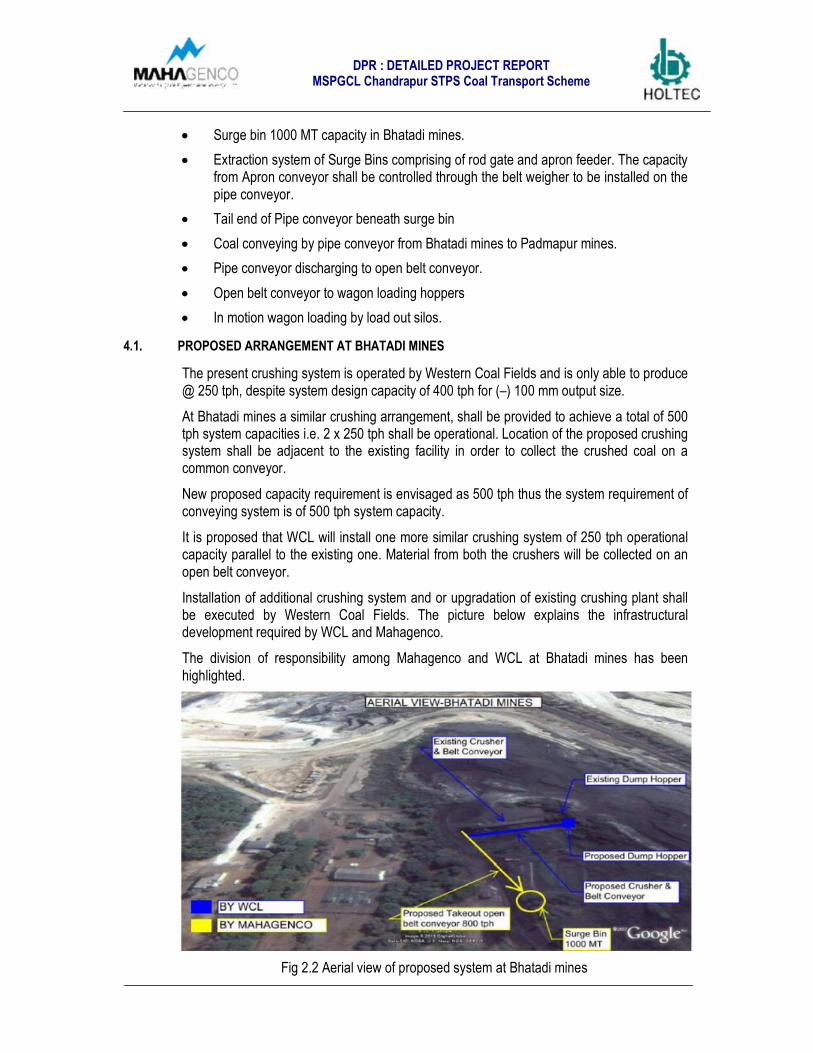
Installation of additional crushing system and or upgradation of existing crushing plant shallbe executed by Western Coal Fields. The picture below explains the infrastructuraldevelopment required by WCL and Mahagenco.
The division of responsibility among Mahagenco and WCL at Bhatadi mines has beenhighlighted.
Fig 2.2 Aerial view of proposed system at Bhatadi mines
DPR : DETAILED PROJECT REPORTMSPGCL Chandrapur STPS Coal Transport Scheme
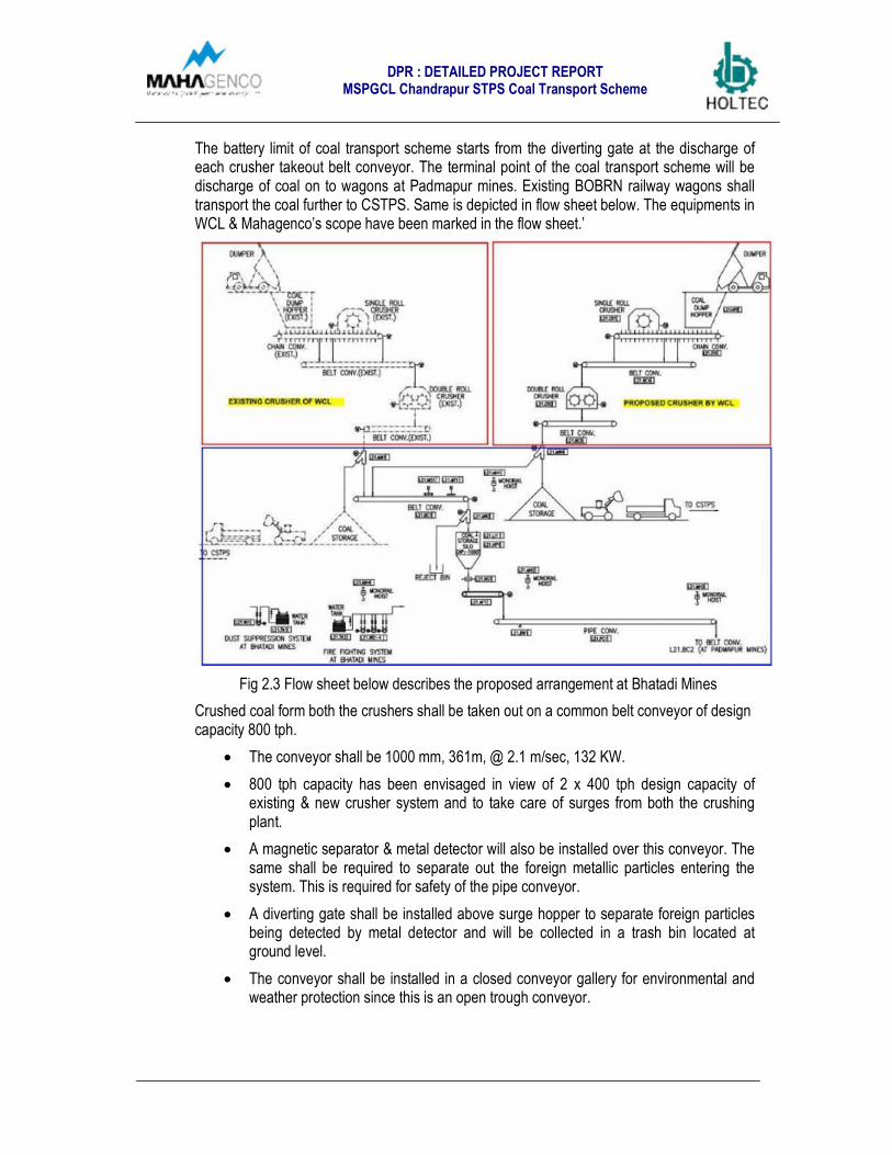
The battery limit of coal transport scheme starts from the diverting gate at the discharge ofeach crusher takeout belt conveyor. The terminal point of the coal transport scheme will bedischarge of coal on to wagons at Padmapur mines. Existing BOBRN railway wagons shalltransport the coal further to CSTPS. Same is depicted in flow sheet below. The equipments inWCL & Mahagenco’s scope have been marked in the flow sheet.’
Fig 2.3 Flow sheet below describes the proposed arrangement at Bhatadi Mines
Crushed coal form both the crushers shall be taken out on a common belt conveyor of designcapacity 800 tph.
• The conveyor shall be 1000 mm, 361m, @ 2.1 m/sec, 132 KW.
• 800 tph capacity has been envisaged in view of 2 x 400 tph design capacity ofexisting & new crusher system and to take care of surges from both the crushingplant.
• A magnetic separator & metal detector will also be installed over this conveyor. Thesame shall be required to separate out the foreign metallic particles entering thesystem. This is required for safety of the pipe conveyor.
• A diverting gate shall be installed above surge hopper to separate foreign particlesbeing detected by metal detector and will be collected in a trash bin located atground level.
• The conveyor shall be installed in a closed conveyor gallery for environmental andweather protection since this is an open trough conveyor.

DPR : DETAILED PROJECT REPORTMSPGCL Chandrapur STPS Coal Transport Scheme
Fig 2.4 Plan view conveyor L21BC1 discharging to surge hopper
Fig 2.5 Profile of conveyor L21BC1 discharging to surge hopper
The conveyor shall discharge the crushed coal to a surge hopper of 10.2 m inside diameterhaving a capacity of 1000 MT.
• 1000 MT capacity has been envisaged considering 2 hrs storage of both thecrushing plant.
• The surge bin is envisaged in steel construction with TOS level +31.15 m level.
• The bin will be equipped with liners for protection against wear & tear.Sailma/Tiscral hard liners have been envisaged. Countersunk bolted design fixing ofliners will make liners to be replaced easily in future.
The arrangement is exhibited by the General arrangement as shown in the figure:
Plan View Elevation
Fig 2.6 Plan view & Elevation of Surge Hopper

DPR : DETAILED PROJECT REPORTMSPGCL Chandrapur STPS Coal Transport Scheme
For extraction of coal from surge bin an apron feeder will be installed.
• 625 tph design & 500 tph rated capacity, matching to down the line pipe conveyorhas been envisaged.
• A belt weigher shall also be installed over straight portion of pipe conveyor to controlthe feed from apron feeder i.e. Apron feeder shall be synchronized with the beltweigher.
• A VFD driven apron feeder will extract the material in a controlled way and providepipe conveyor a consistent discharge.
• Apron feeder will be installed at + 5 m level on a steel platform.
• Expected size of the apron feeder comes out to be 1400 mm x 3500 mm.
• A rod gate shall be provided above apron feeder to control the flow of material fromsurge bin and for maintenance purpose.
Plan View Elevation
Fig 2.7 Plan view & Elevation of Apron feeder below Surge Hopper
Pipe conveyor shall be installed at the discharge of apron feeder as shown in the figureabove.
• The tail end of the pipe conveyor shall be provided with one of the drive for theconveyor.
4.2. PROPOSED ARRANGEMENT OF PIPE CONVEYOR CONVEYING
The pipe conveyor shall receive the feed from surge bin and then close to form a pipe andconvey the material to the Padmapur mines following the Route IA.
As shown in the figure below the pipe conveyor goes first through WCL, and thensubsequently passes through a small patch of private land for approximately 0.77 KM andthen enters Padmapur mines .

DPR : DETAILED PROJECT REPORTMSPGCL Chandrapur STPS Coal Transport Scheme
Fig 2.8 Layout of Pipe Conveyor from Bhatadi Mines to Padmapur Mines
Private land acquisition is required by Mahagenco for 0.77 KM length x 20 m wide stretch.Approx 15400m2 has been envisaged to be procured by Mahagenco, where conveyorpasses through private land.
Mahagenco also needs to coordinate with WCL Bhatadi as well as WCL Padmapur forallocation of land for this conveyor.
Beside the conveyor a service road need to be constructed for approach, erection,inspection /maintenance purpose. 5 m wide service road has been envisaged along thelength of the conveyor. The service road will also be connected to the nearby existing roadsin the Bhatadi & Padmapur area for connectivity.
Fig 2.9 Route Traversal - Pipe Conveyor
DPR : DETAILED PROJECT REPORTMSPGCL Chandrapur STPS Coal Transport Scheme
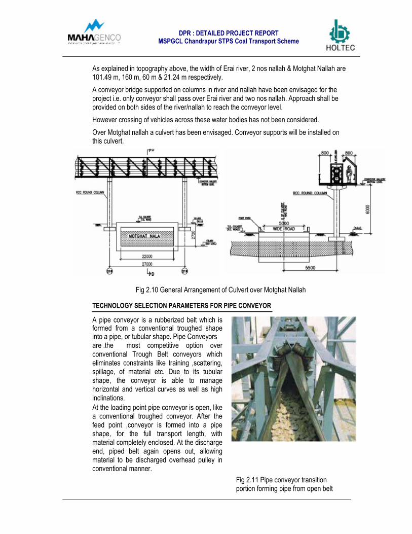
As explained in topography above, the width of Erai river, 2 nos nallah & Motghat Nallah are101.49 m, 160 m, 60 m & 21.24 m respectively.
A conveyor bridge supported on columns in river and nallah have been envisaged for theproject i.e. only conveyor shall pass over Erai river and two nos nallah. Approach shall beprovided on both sides of the river/nallah to reach the conveyor level.
However crossing of vehicles across these water bodies has not been considered.
Over Motghat nallah a culvert has been envisaged. Conveyor supports will be installed onthis culvert.
Fig 2.10 General Arrangement of Culvert over Motghat Nallah
TECHNOLOGY SELECTION PARAMETERS FOR PIPE CONVEYOR
A pipe conveyor is a rubberized belt which isformed from a conventional troughed shapeinto a pipe, or tubular shape. Pipe Conveyorsare .the most competitive option overconventional Trough Belt conveyors whicheliminates constraints like training ,scattering,spillage, of material etc. Due to its tubularshape, the conveyor is able to managehorizontal and vertical curves as well as highinclinations.
At the loading point pipe conveyor is open, likea conventional troughed conveyor. After thefeed point ,conveyor is formed into a pipeshape, for the full transport length, withmaterial completely enclosed. At the dischargeend, piped belt again opens out, allowingmaterial to be discharged overhead pulley inconventional manner.
Fig 2.11 Pipe conveyor transitionportion forming pipe from open belt

DPR : DETAILED PROJECT REPORTMSPGCL Chandrapur STPS Coal Transport Scheme
Pipe conveyor system provides following benefits:-
Spillage Free Transportation as the same is totally closed conveying system. Coalwill be carried inside the pipe formed.
No build up on idlers
Can negotiate horizontal and vertical curves
It may transport material both side (Carrying & Return side). However thisadvantage cannot be utilized in our case.
Has excellent belt edge damage control unlike open belt conveyor.
Unaffected by wind and rain thus requires no covers
Reduced structural costs by eliminating covered galleries.
Cost effective in comparison to conventional conveyor with one or more transfers.
Detailed Engineering Aspects of Pipe Conveyor are as follows:
Basic Engineering Parameters:
Capacity : 500 tph
Radius of Curvature : 250 m
Speed of the conveyor : 3.0 m/sec
Pipe diameter : 350 mm
Installed power : 2 x 450 KW @ head end & 1 x 450 KW at tail
end Belting
Rating : St1400 6+6 (Steel cord belt)
Overlap of the belting : approx 100 mm
Minimum transition distance : 20 m (from open section to pipe forming)
Scrapers : External Segmented Tungsten Carbide tip scrapers
for belt cleaning.
Height of Structure
Clear height : 4 m from ground level, 5.5 m at road crossings
Minimum height of conveyor above water bodies : at least 3 m clear abovehighest flood level.
For crossing of conveyor below the HT lines – keeping a safe gap of 5 m fromthe bottom most conductors.
For the crossing of MV and LT power lines – these shall be crossed by rerouting ofthe conductors underground.
Maintenance
Walkway shall be provided on both sides of the pipe conveyor. Width of walkwayhas been considered as 800 mm. Approach from ground level will also be providedin between say at an interval of 1 KM. Provision for restricted access at the walkwaylevel to ensured by providing lock arrangement.
Lighting shall be provided on one side of the walkway.

DPR : DETAILED PROJECT REPORTMSPGCL Chandrapur STPS Coal Transport Scheme
• A service road has been envisaged for maintenance of the pipe conveyor. Serviceroad shall be made up of compacted gravel. WBM Dirt road has been consideredalong with conveyor. In addition to this approximately 100 m patch of WBMbituminous road has been considered in both Bhatadi & Padmapur mines. Thesebituminous roads shall be connected to the existing roads of Bhatadi & Padmapurmines. Lighting has been envisaged only on the conveyor gallery. For Service roadno lighting has been considered.
Gallery & Support Structure
• The supports for pipe conveyor gallery have been envisaged as RCC construction.
• The interval of support has been considered as 25 m. At road crossings theelevation of the conveyor gallery (Bottom of steel) has been envisaged as +5.5.00 mlevel. Rest of the potion of the conveyor has been considered as +4.00 m level.
Safety Provision:
• Pull chord switch: Pull chord @ interval of 30 m distance along full length of theconveyor.
• Rip Detection : To detect any damage to belt during operation.
• Alarm:
• Electrical Lighting arrangement
• Fire Protection
Constructional Features:
Arrangement of idlers:
Various design of idlers arrangement at pipe section are available. In standard design all sixidlers are placed in one plane and in one design three idlers are placed in one plane and restthree in other plane with overlap of idler length as shown in the figure below:
Fig 2.12 Diagram showing difference in idlers arrangement
The picture above shows the arrangement of idlers i.e. 3 idlers placed on either side of thesupport frame (figure in red) compared to Figure 2 below which has all 6 idlers on one side(figure in blue).
Overlap of the idlers as in Figure eliminates the possibility of belt damage as indicated inFigure in blue.
DPR : DETAILED PROJECT REPORTMSPGCL Chandrapur STPS Coal Transport Scheme
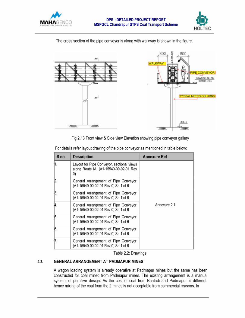
The cross section of the pipe conveyor is along with walkway is shown in the figure.
Fig 2.13 Front view & Side view Elevation showing pipe conveyor gallery
For details refer layout drawing of the pipe conveyor as mentioned in table below:
S no. Description Annexure Ref
1. Layout for Pipe Conveyor, sectional viewsalong Route IA. (A1-15540-00-02-01 Rev0)
Annexure 2.1
2. General Arrangement of Pipe Conveyor(A1-15540-00-02-01 Rev 0) Sh 1 of 6
3. General Arrangement of Pipe Conveyor(A1-15540-00-02-01 Rev 0) Sh 1 of 6
4. General Arrangement of Pipe Conveyor(A1-15540-00-02-01 Rev 0) Sh 1 of 6
5. General Arrangement of Pipe Conveyor(A1-15540-00-02-01 Rev 0) Sh 1 of 6
6. General Arrangement of Pipe Conveyor(A1-15540-00-02-01 Rev 0) Sh 1 of 6
7. General Arrangement of Pipe Conveyor(A1-15540-00-02-01 Rev 0) Sh 1 of 6
Table 2.2: Drawings
4.3. GENERAL ARRANGEMENT AT PADMAPUR MINES
A wagon loading system is already operative at Padmapur mines but the same has beenconstructed for coal mined from Padmapur mines. The existing arrangement is a manualsystem, of primitive design. As the cost of coal from Bhatadi and Padmapur is different,hence mixing of the coal from the 2 mines is not acceptable from commercial reasons. In

DPR : DETAILED PROJECT REPORTMSPGCL Chandrapur STPS Coal Transport Scheme
view of this a new in motion wagon loading system needs to be constructed at Padmapurmines for Bhatadi coal.
Under these loading hoppers BOBRN type wagon will be loaded and then subsequentlytransported to Unit 5, 6 & 7 of CSTPS.
Fig 2.14 Aerial view of the proposed wagon loading system at Padmapur Mines
The proposed system consists of pipe conveyor discharge to open belt conveyor. Open beltconveyor further takes the material to the wagon loading hoppers and then wagon loadingtakes place with helps of gates installed below the hoppers.
Fig 2.15 Flow Sheet of proposed wagon loading system at Padmapur Mines
Since the space available between the 2 existing railway track is only 5.5 m, the width ofwagon loading hopper building have a limitation of width. In view of the limited spaceavailability 3 x 650 MT capacity hoppers have been envisaged for the project. All the 3hoppers will be in steel construction on RCC framework.

DPR : DETAILED PROJECT REPORTMSPGCL Chandrapur STPS Coal Transport Scheme
Pipe conveyor head end will be driven by two nos MV motors of 2 x 450 KW i.e. heavy loadsare foreseen due to belt tension. To avoid the same over wagon loading hopper top, which isplaced on a slender building, a transfer tower and an open belt conveyor has beenintroduced in the system, i.e. pipe conveyor discharge coal to open belt conveyor & beltconveyor takes the material to the wagon loading hopper top.
The pipe conveyor shall discharge on an open belt conveyor installed at ground level. Openbelt conveyor of 500 tph rated capacity and 625 tph design capacity has been envisaged.
• The conveyor shall be 1000 mm, 147m @ 2.5 m/sec, 110 KW.
• The conveyor shall be installed in a closed conveyor gallery for environmental andweather protection since this is an open trough conveyor.
The layout is shown as per plan below:
Fig 2.16 Plan showing the conveyor discharging the material to loading hoppers
The head end of the pipe conveyor with heavy drive arrangement will be located in thetransfer tower, which will be a separate structure than wagon loading hopper building.Drawing below explains the arrangement.
Fig 2.17 Plan view showing the head end arrangement of the pipe conveyor
As shown in the figure above two no’s motor shall drive the pipe conveyor.
• Pipe conveyor coming from Bhatadi mine discharges the coal to open belt conveyorinstalled beneath the pipe conveyor.

DPR : DETAILED PROJECT REPORTMSPGCL Chandrapur STPS Coal Transport Scheme
• Curved monorail hoist has been envisaged over the head pulley to take care ofmaintenance needs of the drive arrangement of the pipe conveyor.
Fig 2.18 Elevation showing the pipe conveyor discharging material to open belt conveyor
As shown in the figure above the pipe conveyor discharge the material to the belt conveyorand this material is further conveyed to the top of wagon loading hoppers.
• The limitation of track width has been tackled by providing this transfer tower sincewidth of the pipe conveyor head end could not be accommodated on wagon loadinghoppers.
• The advantage of the transfer tower is apparent from the fact that the loads of theheavy drive arrangement & take up system of the pipe conveyor will not betransferred to the wagon loading hoppers at +31 m level.
• The height of the wagon loading hoppers will be reduced since the pipe conveyorwill not discharge directly to the wagon loading hoppers.
For faster loading of rakes, an In Motion train loading system, with load out silos of capacity3x 650 t is envisaged.
• This is in view of limitation of the space between existing rail tracks which is 5.5 m.
• The total capacity of wagon loading hoppers i.e. approx 2000 MT has beenconceived with a fact that total 24 wagons can be placed at a time which can beeasily loaded by 2000 MT of coal available in the wagon loading hoppers.
• The material distribution takes place by means of diverting gate at the discharge ofbelt conveyor & reversible belt conveyor of 625 tph designed and 500tph ratedcapacity installed above the loading out hoppers. Level indicator will be installed atthe hoppers.

DPR : DETAILED PROJECT REPORTMSPGCL Chandrapur STPS Coal Transport Scheme
The hopper elevation shown below explains the arrangement.
Front Elevation Side
Elevation Fig 2.19 Front & Side Elevation of the wagon loading hoppers.
• The material flow below the hoppers is controlled by double bladed slide gate &clam shell gates at each hopper discharge. Capacity of the gates has beenenvisaged as 2400 tph – 3600 tph.
• The gates open to load material to BOBRN wagons when the proximity sensorssense the wagon below the hopper.
At CSTPS end, 2 set of track hoppers for unloading of wagons already exists. These trackhoppers are well connected with Unit 5, 6 and 7 of CSTPS. Hence infrastructural facilitydevelopment is not required at CSTPS.
5. UTILITIES AND SERVICES
5.1. WATER SUPPLY
No major process water requirement is envisaged for the proposed system. At Bhatadi aswell as Padmapur end, water will be mainly required for fire fighting and dust suppressionsystem only.
Fire fighting water needs will not be on continuous basis, however dust suppression systemshall consume water on continuous basis.
At Bhatadi end approximately 3-4 m3/hr of water will be required for dust suppression. Twono’s water tanks of about 50 m3 and 100 m3 shall be constructed for dust suppression andfirefighting respectively.
At Padmapur end about 6-8 m3/hr of water will be required for dust suppression. 2 watertanks of about 50 m3 and 100 m3 shall be constructed for dust suppression and firefightingrespectively.

DPR : DETAILED PROJECT REPORTMSPGCL Chandrapur STPS Coal Transport Scheme
Mahagenco needs to arrange water for fire fighting & dust suppression requirements at boththe mines as source of water at the both the mines is not known. Water tank will be built byEPC contractor and pumping and distribution of the same up till the consumption points willbe done by EPC contractor only.
5.1.1. Fire Fighting System.
Coal being a hazardous commodity to handle & transfer, fire fighting system shall be requiredfor pipe conveyor system at feed end (Bhatadi mines area) and discharge end (Padmapurmines area). Fire fighting system at intermediate portion will not be required since pipeconveyor is a closed conveying system.
The proposed fire fighting system comprise of tank (common for dust suppression systemand fire fighting requirement). Pumps for fire fighting and subsequent piping and hydrantsystem.
The proposed fire fighting system shall be as follows:
Fire protection system will be meant to combat fire mishaps as coal handling inside mines areconsidered as “High Hazard”. The fire protection system should be designed as per TACguidelines.
The fire fighting system will comprise of the following
• Water tank of approximately 100 m3.
• Fire fighting pumps including electric pump, diesel engine operated pump and ajockey pump.
• Fire hydrants system will be laid down covering open belt conveyor, surge bin andopen part of the pipe conveyor. Fire escape hydrants will be provided in transfertowers, surge hopper building & wagon loading hopper building.
• MVWS system for part of conveying system where open conveying of coal is beingdone. Fire Alarm & Detection system should also be provided for MVWS system tooperate in remote.
Fire fighting system will be separate for Bhatadi & Padmapur mines.
Fig 2.20 Plan view of Tank & Pump Room Arrangement

DPR : DETAILED PROJECT REPORTMSPGCL Chandrapur STPS Coal Transport Scheme
5.1.2. Dust Suppression System
Dust suppression system will be required at each transfer point. Water based dustsuppression system has been envisaged for the coal transport system. Following are thepoints which shall be covered by dust suppression system.Bhatadi Mines
• Feed point of open belt conveyor at Bhatadi mines• Discharge of belt conveyor to Surge Hopper• Extraction system of Surge hopper including apron feeder• Feed Point of Pipe Conveyor
Padmapur Mines
• Discharge point of the pipe conveyor & feed point of open belt conveyor at Padmapurmines
• Discharge point of the belt conveyor at each wagon loading hoppers & reversible beltconveyor
• Discharge of reversible belt conveyor
Dust suppression system consists of storage tank one at Bhatadi mines & one at Padmapurmines, pumps for pumping water from tank to consumption points, distribution pipelinesystem along with nozzles. Dust suppression system shall be separate for Bhatadi &Padmapur mines.
6. TECHNICAL SPECIFICATIONS
The technical specifications of the equipments are as follows:
Sn.Equipment
TagDescription UOM Quantity
TechnicalSpecifications
1 Bhatadi Mines
1.1 Diverting Gate nos 2
Capacity Tph 400
Sizemm xmm
400 x 400
1.2 Belt Conveyor nos 1
Material Handled Coal
Density of material t/m3 0.8 (Volm)/0.96 (Power)
Capacity tph 800
C/C distance(approx.)
m361.25
Lift m 36.65
Width mm 1200
Speed m/sec 2.0
Temperature oC Ambient

DPR : DETAILED PROJECT REPORTMSPGCL Chandrapur STPS Coal Transport Scheme
Sn.Equipment
TagDescription UOM Quantity
TechnicalSpecifications
Gear Unit withCouplings
1
Electric Motor 1
Speed of shaft rpm 1500
Drive power(tentative)
kW132
1.3MagneticSeparator
Location At L21.BC1
Suitable forbelt width
mm 1200
Electric Motor 1
Speed of shaft rpm 1500
Drive power(tentative)
kW
1.4 Metal Detector 1
Location At L21.BC1
Suitable forbelt width
mm 1200
1.5 Diverting Gate nos 1
Capacity Tph 800
Sizemm xmm
650 x 650
1.6 Trash Bin 1
Size MT 0.5
1.7 Surge Bin nos 1
Capacity MT 1000
Dia x Height m x m 10.2 x 24.75
Hopper ValleyAngle
Deg 60 Deg
MOC Steel , IS 2062
1.8 Liners of Bin set 1MOC Sailhard, TiscralThickness mm 10 mmType-Bolted/Welded
CSK Bolted
1.9 Rod gate nos 1MOC IS 2062

DPR : DETAILED PROJECT REPORTMSPGCL Chandrapur STPS Coal Transport Scheme
Sn.Equipment
TagDescription UOM Quantity
TechnicalSpecifications
Sizemm xmm
To suit surge binoutlet
Capacity tph625 tph design,500 tph rated
1.10 Apron Feeder nos 1
Material Handled Coal
Density of material t/m3 0.8 (Volm)/0.96 (Power)
Width mm 1400Length M 3.5
Capacity tph625 tph design,500 tph rated
Temperature Deg C Ambient
Electric Motor(VFD driven)
1
Speed of shaft rpm 1500
Drive power(tentative)
kW75
1.11Dust suppressionsystem (BhatadiMines)
set 1
No of Pumps 2 (1 W + 1 S)
No of consumptionpoints
4
Pipeline lengthapprox
KM As per layout
MOC of nozzles GI galvanized
1.12Fire FightingSystem (BhatadiMines)
set 1
No of Pumps 3Pipeline lengthApprox
KM As per layout
No of Hydrants As per TAC normsNo of DelugeValves
As per TAC norms
MOC of nozzles forMVWS system
GI galvanized
2 Conveying system2.1 Pipe Conveyor
Material Handled Coal
Density of material t/m3 0.8 (Volm)/0.96 (Power)
Capacity tph 500

DPR : DETAILED PROJECT REPORTMSPGCL Chandrapur STPS Coal Transport Scheme
Sn.Equipment
TagDescription UOM Quantity
TechnicalSpecifications
Belt Width mm 1400Length (Truelength)
KM 5.6
Pipe Dia mm 350Speed m/sec 3Temperature Deg C Ambient
Gear Unit withCouplings
1
Electric Motor 3 MV Drive
Speed of shaft rpm 1500
Drive power(tentative)
kW 13502 x 450 KW at
Head End1 x 450 KW at Tail
end
2.2 Belt Weigher 1
Location At L21.BC1
Suitable forbelt width
mm 1200
3 Padmapur Mines
3.1 Belt Conveyor nos 1
Material Handled Coal
Density of material t/m3 0.8 (Volm)/0.96 (Power)
Capacity tph 625
Width mm 1000
Speed m/sec 2.5
Length c/c m 147.6
Lift m 36.8
Gear Unit withCouplings
1
Electric Motor 1
Speed of shaft rpm 1500
Drive power(tentative)
kW110
3.2Reversible Beltconveyor
nos 1
Material Handled Coal
Density of material t/m3 0.8 (Volm)/

DPR : DETAILED PROJECT REPORTMSPGCL Chandrapur STPS Coal Transport Scheme
Sn.Equipment
TagDescription UOM Quantity
TechnicalSpecifications
0.96 (Power)
Capacity tph 625
Width mm 1000
Speed m/sec 2.5
Length c/c m 16.6
Lift Horizontal
Gear Unit withCouplings
1
Electric Motor 1
Speed of shaft rpm 1500
Drive power(tentative)
kW15
3.3 Diverting Gate nos 1
Capacity Tph 625
Sizemm xmm
500 x 500
3.4Wagon LoadingHopper
nos 3
Capacity of eachhopper
MT 650
Dia x Height m x m 7.8 x 25.7
Hopper ValleyAngle
Deg 60
3.5 Liners of Bin set 3
MOC
Thickness mm 10
Type-Bolted/Welded
CSK Bolted
3.6Double BladedSlide gate
nos 3
Capacity Tph 2400-3600
Sizemm xmm
To suit the wagonloading hopper
opening
3.7 Control Gate nos 3
Capacity Tph 2400-3600
Sizemm xmm
To suit the wagonloading hopperopening & rod
gateInstalled KW KW

DPR : DETAILED PROJECT REPORTMSPGCL Chandrapur STPS Coal Transport Scheme
Sn.Equipment
TagDescription UOM Quantity
TechnicalSpecifications
3.8 Telescopic Chute 3
Capacity tph 2400-3600
Expanded Height mm 1500
Installed Power KW 5.5
3.9Dust suppressionsystem (PadmapurMines)
set 1
No of Pumps 2 (1 W + 1 S)
No of consumptionpoints
4
Pipeline lengthapprox
KM As per layout
MOC of nozzles GI galvanized
3.10Fire FightingSystem
(Padmapur Mines)set 1
No of Pumps 3
Pipeline lengthApprox
KM As per layout
No of Hydrants As per TAC norms
No of DelugeValves
As per TAC norms
MOC of nozzles forMVWS system
GI galvanized
Table 2.3: Technical Specifications of the equipments
7. INSTALLED LOAD REQUIREMENT
The likely power requirements (which need to be arranged by Mahagenco) shall be:
S No. Description Connected Load (KW)
1POWER REQUIREMENT AT BHATADI MINES (WITHOUTCRUSHING SYSYTEM)
1.1 CONVEYING SYSTEM1.2.1 LT Power 250-3001.2.2 MV Power 450
TOTAL CONNECTED LOAD) 700-750Say 0.75 mW
2POWER REQUIREMENT AT WAGON LOADING SYSTEM- PADMAPURMINES
2.1 LT Power 400 - 450

DPR : DETAILED PROJECT REPORTMSPGCL Chandrapur STPS Coal Transport Scheme
S No. Description Connected Load (KW)2.2 MV Power 900
TOTAL CONNECTED LOAD 1300 - 1350Say 1.5 mW
Table 2.4 Load Distribution
8. ELECTRICAL & INSTRUMENTATION ENGINEERING
8.1. POWER SOURCES
Incoming power shall be received at 33 KV, 50 Hz at two locations one shall be nearPadampur bulk loading station electrical loads and other near Bhatadi surge hopper (L21HP1).As the locations of incoming power in both the areas are not finalized hence these powersources assumed approximately 200 meters away from respective departmental load centers.At both location power will be step down to 6.6KV with help of 2.5MVA, 33/6.9KV powertransformers and feed to 6.6KV MV boards. Both the locations scope for the project shall startfrom connected to outgoing 33kV isolator as clearly defined in single line diagram no. “A3-15540-E1-04-01, Rev.0” attached as Annexure 2.2
1.5MW connected load has been envisaged for Padampur area. 1.5MW total connected loadhas been envisaged at mine coal transport conveying system including new coal crusher inmines. 0.75MW connected load has been considered for coal crusher and 0.75MW connectedload has been considered for coal transport conveying system. However scope for this projectis limited to outgoing feeder in MV switchboard assigned for new coal crusher. Any powerdistribution for coal crusher area including cables from outgoing feeder to new coal crusherdepartment not considered in the scope of project.
8.2. POWER DISTRIBUTION & LOAD CENTRES
In both location powers received at 33KV shall be step down to 6.6kV. Major consumer ofpower is variable speed motors for pipe conveyor considered at both locations. For thesevariable speed drives the voltage level for the motor considered is 690V. One 3 windingtransformer at each location envisaged to feed the 690V variable speed drives. For LVequipment one distribution transformer & LV distribution board considered in both location
For maintenance power & lighting requirement of all over pipe conveyor, one small distributiontransformer has been envisaged in the middle of pipe conveyor.
For clear understanding of power distribution refer attached single line diagram no. “A315540-E1-04-01, Rev.0”.
The following Load Centers are envisaged:
Load Centre (LC) 01 : S ilo Extraction Electrical Room (Padampur)
Load Centre (LC) 02 : Pipe Conveyor Intermediate Electrical Room
Load Centre (LC) 03 : C oal Handling Electrical Room (Bhatadi)
For details refer attached layout diagram no. “A1-15540-00-02-01, Rev.0”.
DPR : DETAILED PROJECT REPORTMSPGCL Chandrapur STPS Coal Transport Scheme
8.3. 33 KV SWITCHBOARD
The 33 kV indoor, ICOG switchboard shall be assembled in a line up of factory fabricated,metal clad cubicles with draw out type truck-mounted circuit breakers installed at LC-01 & LC-03 to receive 33kV power supply & fed to 2.5MVA transformer. Vacuum circuit breakers shallbe used. The incoming cum outgoing feeder shall also be operated from a remote. Switchgear shall have necessary metering, protection and control functions to suit the applicationthrough multifunction meters & composite microprocessor based numeric relays having serialbus compatibility with PLC based plant control system.
8.4. 33! 6.6 KV POWER TRANSFORMERS
One suitable rating 3 phase, Dyn11, oil type, copper wound power transformer have beenenvisaged at both location, which shall step down the power from 33kV to 6.6kV. This powertransformer will fed power to suitable rated MV switchboards to cater the power requirement ofnew proposed Bhatadi coal conveying area, Padampur silo feeding, silo extraction & wagonloading area. These transformers will have ONAN cooling and 'ON' Load Tap Changer facilityto ensure constant 6.6kV voltage even fluctuation in 33kV side.
8.5. 6.6 KV SWITCHBOARDS
The 6.6 kV switchboards shall be assembled in a line up of factory fabricated, metal cladcubicles with draw out type truck-mounted circuit breakers installed at LC-01 & LC-03.Vacuum circuit breakers shall be used. The incoming and outgoing feeders shall also beoperated from a remote. Each switch gear shall have necessary metering, protection andcontrol functions to suit the application through multifunction meters & compositemicroprocessor based numeric relays having serial bus compatibility with PLC based plantcontrol system.
For details refer attached single line diagram no. “A3-15540-E1-04-01, Rev.0”.
8.6. DC CONTROL POWER SUPPLY
The switchgear shall be complete with a control power supply, including battery rack, chargingequipment and a distribution panel. The DC distribution shall consist of battery and batterycharger with float cum boost charger with battery back up of 10 hours.
8.7. 6.6 KV LOAD BREAK SWITCH
For maintenance power & lighting requirement of all over pipe conveyor, one small distributiontransformer has been envisaged in the middle of pipe conveyor. The power supply to thetransformer fed from LC-3, hence suitable 6.6kV load break switch considered near thesetransformer in LC-02.
8.8. 6.6! 0.433 KV DISTRIBUTION TRANSFORMERS
One suitable rating 3 phase, Dyn11, dry type, copper wound distribution transformers havebeen installed in each electrical room, which shall step down the power from 6.6kV to0.433kV, These distribution transformers will feed power to suitable rated LT switchboards(PMCC) to cater the power requirement of new proposed Bhatadi coal handling area,

DPR : DETAILED PROJECT REPORTMSPGCL Chandrapur STPS Coal Transport Scheme
Padampur silo feeding, silo extraction & wagon loading area. These transformers will havenatural cooling with 'OFF' Load Tap Changer.
8.9. LOW VOLTAGE 415 V DISTRIBUTION BOARD
Conventional type PMCC along with all other necessary electrical components shall beinstalled in LC01, LC-02 and LC03. The PMCC shall have fully drawn out, motor operated aircircuit breakers incomer with necessary safety features to facilitate safe operation and easymaintenance and fixed type outgoing feeders.
8.10. POWER FACTOR IMPROVEMENT
There is no HT motor but 690V VFD has been considered which is designed to maintainpower factor in the range 0.96. Hence, we have considered any compensation on MV bus.
For compensation on LT, multi-step automatic controlled capacitor banks have beenconsidered. The capacitor banks have been sized to maintain the overall power factor of 0.96lag.
Considering very less loading on middle of transformer we are not considering power factorcorrection on LC - 02.
Power factor at crusher side shall be maintained at crusher end MV/LV distribution and not inthis project scope.
8.11. 690V MOTORS
690V VFD application motors are considered only for pipe conveyor. The variable speedmotors shall be squirrel cage type motors suitable for VVVF application. These motors will beof Protection Class IP55 with TEFC enclosure. In case if required force cooling fan shall beconsidered for external cooling.
All motors shall be furnished with class F insulation. The required motor size shall bedetermined on the basis of a loading according class B temperature increase. If motors arede-rated due to ambient factors, IS/IEC-as well as reduced data shall be indicated onnameplates. The specified ambient temperature shall be considered for motor design.
8.12. LOW VOLTAGE MOTORS
Induction motors shall be used for constant speed drives. All motors shall be totally enclosedfan cooled (TEFC) enclosure and protection type IP55.
For any variable speed application motor shall be VFD grade motor.
8.13. DRIVES
The types of drives considered are based on the following requirements:
v' Load Characteristics
v' Starting Torque

DPR : DETAILED PROJECT REPORTMSPGCL Chandrapur STPS Coal Transport Scheme
v' Operating characteristic i.e. high power factor and efficiency at operating points
v' Accuracy and range of speed control required for specific applications.
Power saving equipment like Variable Frequency AC drives has been considered for variablespeed applications to reduce energy consumption. Power factor shall be considered as > 0.96P.F.
8.14. EARTHING / LIGHTNING PROTECTION
An earth mat provided with plate earth electrodes and interconnecting earth strips buried inground shall be set up for electrical room earthing and earthing of high and low voltageequipment for the safety of operating personal and protection of electrical equipment as perrequirement of IEC.
Earth pit at regular interval shall be considered in pipe conveyor for pipe conveyor properearthing.
8.15. LIGHTING
An efficient illumination scheme for inside and outside the plant buildings and inside the plantarea has been considered. Sufficient number of lighting distribution boards with timers havebeen considered for automatic control of lighting fixtures at various locations of the plant.
8.16. CABLE & CABLE LAYING
Following types of cables have been considered for the plant:
Power (MV) 33 kV & 6.6 kV, armored, XLPE insulated Aluminum cables
Power (LT) 1.1 kV, armored, XLPE insulated Aluminum cables
Control 1.1 kV grade, screened, armored, PVC
Insulated Copper. 1.0, 1.5 & 2.5 mm2
Instrumentation 1.1 kV grade, screened, armored, PVC
insulated Copper, 0.5 & 1.0 mm2
Table 2.4 Type of Cables
The method of cable lying will minimize fault tracing time, ensure easy accessibility formaintenance and facilitate rapid restoration of supply. Power and control cables shall besegregated by running on separate racks to avoid signal pick-ups.
To minimize the damage to control and instrumentation cables in the event of short circuit inthe power cables, the latter are located in the bottom tier & former are located in the upper tierof the cable racks.
8.17. AIR CONDITIONING SYSTEM AND P&V SYSTEM
In order to maintain the designed measuring and control accuracy of the electroniccomponents, suitable package type or split type window air conditioning system for local

DPR : DETAILED PROJECT REPORTMSPGCL Chandrapur STPS Coal Transport Scheme
control stations and P&V system of adequate capacity have been considered in the allelectrical rooms. The following Load Centers are envisaged with:
Load Centre – 01: P&V System considered for MV & LV switchgear room and Airconditioning system for control room.
Load Centre – 02: Split AC has been considered.
Load Centre – 03: P&V System considered for MV & LV switchgear room and Airconditioning system for control room.
8.18. DOUBLE POLE STRUCTURE FOR 33KV/11KV/6.6KV/415V LINE
33kV/11kV/6.6kV/415V transmission lines are present in pipe conveyor route. Double polestructures with electrical equipments have been envisaged at both side of conveyor forcrossing of transmission line as per requirement.
8.19. CONTROL & INSTRUMENTATON SYSTEM
8.19.1. GENERAL
For effective control of various variables, a system of instrumentation and control has beenconsidered keeping the following objectives in view:
• Dependable and rugged instrumentation network.• Maximum protection against dust and vibrations.• Minimum moving parts.• Operational Safety.• Easy maintenance and repairs.• Flexibility to adopt future development / modifications.• Optimum operating frequency and good quality product.• Maximum standardization to keep inventory low.
8.19.2. PLANT CONTROL SYSTEM
For the control and operation of new proposed coal handling and transport system a localcontrol system comprising of programmable logic controller (PLC) and operator cumengineering stations (OS/ES) with peripherals are considered.
Conceptual control system configuration Dwg No. A3-15540-I1-04-01-R0 shows overallstructure of control system envisaged.
Two Nos. Operator Cum Engineering Stations are considered with original as well floatinglicenses for individual as well as parallel activities like Operation Monitoring and Control,Engineering, Management Information System (MIS) Report Generation, Energy Monitoring,Web access, Anti Virus Safety etc. A control room for these stations shall be located in LC-01of new coal storage and wagon building in such away that all wagon loading spouts can beviewed by operator.

DPR : DETAILED PROJECT REPORTMSPGCL Chandrapur STPS Coal Transport Scheme
For sequential control of drives and supervision of various process and safety variables, aPLC based control system has been considered. The PLC panel shall be located in LC-01. Allthe field devices, drives, sub control system of respective areas shall be connected throughI/O panels at LC-01 and Remote I/O panels at LC-02, LC-03 for real time acquisition ofprocess parameters and Plant safety and fail safe operations. Fiber Optics communication isproposed between Remote I/O panels & HT Board/PMCC MFM/Relays at LC-02, LC-03 &programmable logic controller (PLC) at LC-01.
The control system envisaged incorporates following essential features for safe operation ofplant and machinery and provides necessary operating data to evaluate the operatingperformance and likelihood of faults:
• Human Machine Interface through operator/engineering stations connected todepartment controllers via redundant high-speed data highway. Manageable networkswitches shall be interfacing HMI, Programmable logic controllers etc on the highspeeddata high way for controlling plant operation.
• Plant operation shall be monitored and controlled from the operator/engineering stationcomprising colour monitors, QWERT keyboards, optical mouse / scroll roller etc.Programmable logic controller associated with these operator/engineering stations shalldo sequential logic controls and analogue monitoring.
• Suitable programmable logic controller for sequence interlocking and automatic closedloop control through PI and PID action with required input/output cards.
• Automatic Close Loop Control System.• Serial bus connectivity for VFD, I/O panels, Energy meters, Numeric Relays.• Operating/Engineering stations with mimic pages, indicating various process
parameters and keyboard for start/stop and control of the plant, for trouble shooting andprogramming.
• Programmable logic controller shall have necessary hardware to achieve interlockingbetween the drives in various sections achieving an automatic sequential start and stopscheme. Local control of start and stop can also be done, if necessary, by properselection of remote/local selection switch. In local mode drives can be started/stoppedindependently from local push button station and there shall be no inter-lockingbetween drives.
• Programmable logic shall be used for sequential start/stop of the drives. The starting,stopping and alarm sequences for the drives shall be suitably designed to take care ofoperational and safety requirements.
• MIS/ EMS system for control and monitoring of power engineering data and shallgenerate reports and process mimics as well.
The control system shall be structured as under:
Level – I (Field level)
At Field level the instruments and sensors are installed in accordance with processrequirements. For certain systems like pipe conveyors, belt weigher, and automatic bulkloading systems etc. sub-control systems if required should be envisaged. Hardwiredcommunication with PLC system has been considered for field instruments and sub controlsystems.

DPR : DETAILED PROJECT REPORTMSPGCL Chandrapur STPS Coal Transport Scheme
Level – 2 (Department Control level)
Programmable logic controller with input/ output devices shall ensure safe operation ofmachines and supervise production processes.
Level – 3 (Supervisory level)
Operator stations with supervisory processor visual display unit, keyboards, etc. for efficienthuman/ machine interface for remote operation of the unit like Sequential interlocks for groupstart and stop, Analog signal processing by real time acquisition of plant process parametersfor monitoring of process and safety of equipment.
8.19.3. CONTROL SCHEME
GROUP1 - Coal diversion from diverters L21MW1 & MW3 and Coal Transport & feed toCoal Hoppers L21.HP2
• Control for Motorized Diverter L21MW1 & MW4• Control for Magnetic Separator L21.MS1 and Metal Detector L21.MT1• Control for Coal Transport system Belt Conveyor L21BC1• Control for Motorized Diverter L21MW2• Control for Coal Feed in Coal Hoppers L21.HP2 through Motorised Diverter and
overfilling devices (High level measurement)
GROUP2 - Coal Extraction from Hopper L21.HP2 and Coal Transport & feed toCoal Hoppers L21.HP3, 4, 5
• Control for Apron Feeder L21AF1• Control for Electro-mechanical Belt weigher L21BW1• Control for Coal Transport system i.e. Pipe & Belt Conveyor L21PC1, L21BC2,L21BC3• Control for Coal Feed in Coal Hoppers L21.HP3,4,5 through Motorised Diverter and
overfilling devices (High, Continuous level measurement)
GROUP3 - Coal Extraction from Hopper L21.HP3, 4, 5 and Automatic Wagon Loading
• Control for Coal Hoppers L21.HP3, 4, 5 extractions through clam shell gates.• Control for Wagon loading System• Control for Dust Suppression System
All above mentioned control schemes shall come under plant control system and controlledfrom operator stations situated in LC-01 Control Room, as shown in Conceptual controlsystem configuration Dwg No. A3-15540-I1-04-01-R0.
However, for Group 1, final decisions of operations to be done by Old and New Crusher controlsystem, hence for proper sequencing and control of equipment operation between old & newcoal crusher system and newly proposed coal transport system, Hardwired Permissibledeterministic interlocking at field level proposed between proposed Coal Transport PLC withOld and New Crusher Control System at I/O level for exchange of process parameters. Cablelaying for the same purpose between control system of Old/New Crushers and New Coal

DPR : DETAILED PROJECT REPORTMSPGCL Chandrapur STPS Coal Transport Scheme
Handling System IO Panel will be the reasonability of Proposed Coal transport Systemsupplier. However termination of cables at Old/new crusher control system end will be of theirrespective suppliers.
8.19.4. PROCESS INSTRUMENTATION
An elaborate instrumentation comprising of field sensors, transducers, safety switches shall beset up for monitoring and safety of processes like speed, level, position etc. These devicesshall be linked to control system through I/O panel to display the parameters on OperatorStation and exercise the desired controls. The broad technical features of sensors andinstruments are described below: -
Level Monitoring
Special designed radar type level transmitters shall be deployed for continuous monitoring andcontrol of material level in hoppers..
RF Capacitance/Admittance type High level switches should be deployed to prevent overfillingof hoppers.
Speed Monitoring
These shall be deployed to achieve zero speed protection for various equipments like apronfeeder, pipe conveyors, belt conveyors etc. The unit chosen shall have built in initial by-passtime delay and designed to operate over a range of speed. The primary sensor shall be non-contact type designed to achieve unlimited number of operation. The unit as well as sensorshall have a high degree of environment protection.
Limit Switches
Electro mechanical type limit shall be deployed to control open and close positions for andmotorised material diverters. Torque limit switches should be deployed for the positioning ofmotor of motorised diverters.
Weigh Transmitters
Weigh transmitters shall be deployed to convey the weigh signals to control system from beltweigher units.
Addressable Pull Cord Switches
For Emergency stop of pipe conveyors and belt conveyors for safety purpose, addressabletype pull cord switches shall be deployed on both ends of conveyors at every 50 meters.These switches should be looped to belt watch panels placed in LC-01 and LC-03.Information of any specific pull cord activation will be provided to control system through beltwatch panel.
Addressable Belt Sway Switches
To monitor sway detection of belt conveyors for safety purpose, addressable type belt swayswitches shall be deployed on both ends of belt conveyors at every 50 meters. These

DPR : DETAILED PROJECT REPORTMSPGCL Chandrapur STPS Coal Transport Scheme
switches should be looped to belt watch panels placed in LC-01 and LC-03. Information of anyspecific belt sway activation will be provided to control system through belt watch panel.
8.20. CLOSED CIRCUIT TV (CCTV)
IP based CCTV system for viewing of major transfer point locations of plant shall beemployed. Master control and Main Display unit of system should be located at Control Roomin LC-01. Communication between IP based Cameras and Master control unit shall be FOcommunication.
8.21. FIRE DETECTION & ALARM SYSTEM
Addressable type fire detection & alarm system for all load centers, cable cellars, controlrooms and belt conveyors to be employed. Master control panel of shall be located in controlroom of LC-01 with Field panels in LC-02 and LC-03 respectively. Communication between allthe stations shall be FO communication outside buildings.
8.22. PLANT COMMUNICATION SYSTEM
IP based Telephone System/Public Address System with 12 channels EPBAX envisaged forthe project. Field IP Telephone / PA Telephone Handsets to be placed in electrical/controlrooms, transfer towers, offices etc., in addition handsets will be provided in new and existingcrusher control rooms.
8.23. UNINTERRUPTED POWER SUPPLY
The new locations housings shall have its own UPS (Separate UPS for LC-01,02,03) and shallalso provide power to microprocessor based sub-controls, PLC and I/O panel, HT Panels,PMCC Panels, Operator cum Engineering Station, CCTV, all networking equipments etc. Thecapacity of UPS shall be chosen to cater to such loads and to have some spare capacity aswell. The battery bank shall be 2V, VRLA design, capacity of which shall be chosen to provide30 Minutes backup time minimum.
9. CIVIL ENGINEERING CONSIDERATIONS
9.1. SITE CONDITION AND DESIGN CRITERIA
This section covers the site condition and Design criteria to be considered for designing thestructures used for mechanized material handling system from WCL mines to inside theplant.
9.2. Topography
The general terrain in the area proposed for new coal transport system is more or less flatwith gentle slope and few low lying areas. The land requires certain amount of earth filling,leveling and land preparation. A lump sum provision for site preparation, grading and levelinghas been kept in cost estimate.

DPR : DETAILED PROJECT REPORTMSPGCL Chandrapur STPS Coal Transport Scheme
9.2.1. Subsurface Condition
Presumptive bearing capacities at various depths have been supplied by client for preparinginitial DPR. Geo technical investigation is in progress. As confirmed by Mahagenco the soilstrata at site is moist sand (alluvial deposits) mixed with clay. Possibility of striking subsurface water within founding depth may not be ruled out.
9.2.2. Ground Water
Ground water table of the area is expected to be encountered within founding depths.
9.2.3. Corrosion
Environmental exposure condition is expected to be mild since it is far away from saltyvapors from coastal zones.
9.2.4. Seismicity
The proposed plant – site area falls in Seismic Zone III for which the zone factor is as per IS1893 (Part I): 2002. This aspect shall be duly considered while designing the structures.
The importance factor shall be considered as 1.75
Soil condition is of type weak.
Ductile Detailing provisions of relevant BIS codes shall be applicable.
9.2.5. Wind speed Consideration
The basic wind velocity, as per IS: 875-1987 Part III, is 47.0 mps which can be consideredfor designing the civil structures
Wind loads on various structures shall be calculated based on provisions of IS 875 (P-III)-1987.
9.2.6. Plant Structures
The Civil design and construction of structures for new material handling system have to meetthe load data conditions. As a matter of practice buildings are envisaged to be primarilydesigned in reinforced cement concrete (RCC) with suitable brick wall/ CGI sheet roofingand/or cladding, as required. Structural steel usage shall be limited to sheds, conveyorgalleries, and working platforms or where flexibility of stage-wise constructions is involved.
9.2.7. Structural Design of Storage Structures
In the structural designs of storage structures like Silos, Hoppers etc., thefollowing parameters shall be considered:
PARAMETERS FOR STRUCTURAL DESIGNS OF STORAGE STRUCTURES
Material Bulk Density (Kg./Cu.M.)
Angle of FrictionDegrees
Cement Clinker 1520 30
Cement 1600 20
Gypsum 1600 35

DPR : DETAILED PROJECT REPORTMSPGCL Chandrapur STPS Coal Transport Scheme
Coal 1040 30
Blast Furnace Slag 1440 35
Table 2.5 Structural Design Parameters
9.2.8. Live Loads
Live loads to be considered for design of various floors and roofs shall be as per Table - 2below:
Sl.No. Location For Floor Slabs and SecondaryBeams
1. Non Accessible terrace roofs 75 Kg/m2
2. Accessible terrace roofs 150 Kg/m2
3. Office, control rooms 250 Kg/m2
4. Industrial floors 500 Kg/m2
5. Walkways (gallery) 250 Kg/m2
6. Dust accumulation on floors 50 Kg/m2
7. Electrical rooms 250 Kg/m2
8. Industrial ground slabs 2 tons/m2 or 12 t axle load
Table 2.6 Live Loads
9.2.9. Machinery Loads
In addition to the live loads as specified in 7.1.7, loads imposed by machinery, including theeffect of dynamic characteristics shall be considered. The loads due to the machinery andequipment shall be as specified by the manufacturer. Resonant conditions should beavoided by suitably proportioning the supporting structural members.
9.2.10. Deflection limits for structures
Maximum deflection of various structures shall not exceed and be limited to the following
Sl.No. Description Maximum Value1. For all structures Span/325 or height /325 as the case
be UNO
2. For all beams directly supportingequipments
Span/500
3. For all roof purlins Span/250
4. For all gratings / chequered plates Span/250 or 6mm max.
5. For cladding runners Span/250
Table 2.7 Deflection Limits
9.3. COMPONENT DESIGN CRITERIA
Following table shows the description of building and structures envisaged for the project:
SN Building/structure Description
1 Pipe conveyors and Isolated RCC foundation, RCC Trestle, & Gallery,Walkway in Structural steel. For pipe conveyors open

DPR : DETAILED PROJECT REPORTMSPGCL Chandrapur STPS Coal Transport Scheme
SN Building/structure Description
Belt Conveyors gallery and for normal trough conveyors coveredgalleries with GI sheet covering.
2Intermediate Storage
hoppers – 1 NO(capacity 1000 MT)
Hopper shall be in steel construction on isolated RCCfoundation with top steel shed & cladding.
3Transfer towers(-2 nos)
for conveyorRCC isolated foundations Tie beams & RCC floors &peripheral brick cladding.
4Bulk loading silo
(3x650 MT Capacity)Foundation, tie beams & columns are in reinforcedconcrete .Storage silos are in structure steel.
5Electrical Rooms
(Two nos)
All foundation in concrete however brick wall allaround with steel window, door, and ventilators andwith split Air conditioner.
6 Water tank (two nos)Two no water tank in RCC of capacities 100 cum &50 cum each.(one each at padampur & bhatadi minesincluding pump house).
Table 2.8 Description of Structures
The design criteria which needs to be adopted for the project is as under:
9.3.1. Storage Structures:
Storage silo & hoppers shall be designed for critical combination of dead loads , material fillloads & live loads .
For calculating seismic loads 80% material fill load shall be considered.
Foundations shall be designed for submerged conditions.
9.3.2. Trestles:
Pipe conveyor trestles shall design in RCC for critical load combinations of dead loads, liveloads & equipment loads, wind loads & seismic loads.
Seismic loads & wind loads shall not be considered to act simultaneously.
Foundation of trestles shall be designed for no loss of contact. (Minimum bearing pressureshall not be less than 0.)
Foundation of trestles situated within conveyance zone of river & NALLAH shall be done inminimum flow season. Special temporary retaining & dewatering system shall be adopted asper requirement while constructing these foundations. Hydraulic loads on piers for highestflood condition shall be used in combination with other standard loads while design of thesefoundations. The foundations shall be protected against sour as per local practice.
Limit state of design methods as per IS 456 LATEST shall be used to design all RCCstructures. Two faces reinforcement mesh shall be used for slab 150mm or higher inthickness.

DPR : DETAILED PROJECT REPORTMSPGCL Chandrapur STPS Coal Transport Scheme
Design detailing & fabrication of structural steel members shall be as per provisions of BIS 800latest..
Vertical deflection & lateral sway of structures shall be within allowable limits as per relevantBIS CODES.
9.3.3. Water tanks:
Water tanks shall be designed as uncracked sections as per BIS 3370. The stability of tanksshall be checked assuming water table up to ground level. Permissible crack width shall be0.1mm.
Bottom slab shall be cast horizontal & required slope shall be provided in screed concrete.
Minimum thickness of grade slab shall be 200 mm.
Minimum thickness of wall shall be 225 mm.
Surcharge load of 20 Kn/m2 shall be considered.
For lateral pressure calculation on vertical walls co efficient of pressure at rest shall beconsidered.
Water proofing treatment to tanks shall be done from external box type in dry workingcondition.
Hydro testing of tanks shall be performed for leakages as per BIS 3370 & 6494. In case ofleakages remedial measures shall be taken by contractor as per satisfaction of client. Allconstruction joints shall be provided with PVC water bars.
9.3.4. Service Roads:
The road shall be WBM dirt road. i.e. road made from gravel mainly sand obtained from quarryduly compacted.
The same shall be used only for erection of the pipe conveyor and subsequently formaintenance activities.
9.3.5. Material specification
Concrete
Grade of concrete shall be as follows
Foundations : M25
Superstructures : M30
Water Tanks : M30
Concrete quality control & acceptance criteria shall conform to relevant provisions of BIS 456LATEST.
Reinforcing steel: Fe500D conforming to BIS 1786 latest.
Structural steel: Wieldable structural steel conforming to BIS 2062
Brick Masonry: Brick masonry shall be constructed of bricks of crushing strength not less than105 kg/cm2.

DPR : DETAILED PROJECT REPORTMSPGCL Chandrapur STPS Coal Transport Scheme
9.3.6. Building Materials
The following major materials shall be used for construction of the buildings:
Cement
Ordinary Portland, or Portland pozzolana cement conforming to IS: 269, IS: 1489 or IS: 455shall be used.
Reinforcement
Plain Mild Steel Reinforcement
Plain mild steel reinforcement rods shall conform to Grade-I of IS: 432, (Part 1). The minimumguaranteed yield strength shall be 260 N/Sq.mm. The dia of plain mild steel reinforcementrods to be used shall be:
10mm, 12mm, 16mm, 20mm and 25mm.
High Yield Strength Deformed Bars
High Yield Strength Deformed Bars shall conform to IS: 1786 of Grade Fe500D. Theguaranteed yield strength shall be 500 N/Sq.mm. The diameter of high yield strengthreinforcement bars to be used shall be:
8mm, 10mm, 12mm, 16mm, 20mm, 25mm, 28m and 32mm.
Structural Steel
All structural steel sections shall conform to IS: 2062.
Corrugated Galvanized Iron Sheeting
Roofs of structural sheds shall be provided with 22/24 gauge corrugated galvanized ironsheeting. The lengths of sheets to be used are:
1800mm, 2500mm, 3000mm

DPR : DETAILED PROJECT REPORTMSPGCL Chandrapur STPS Coal Transport Scheme
9.4. DETAIL DESCRIPTION OF BUILDINGS & STRUCTURE
BUILDING CHARACTERISTICS: SURGE HOPPER AT BHATADI MINES
Project MSPGCL-Chandrapur STPS Coal Transport Scheme
DESCRIPTION
Foundation RCC Equipment Foundation NA
Beams & Columns RCC Crane Beam Monorail for Conveyor
Pits & Tunnel NA Roof Structure Steel
Ceiling NA Roof Covering Corrugated Sheets
Floor Slab Steel Floor Flooring Chequered Plates
Ground NA Wall Storage silos in steel
Exterior Wall
SurfaceNA
Interior Wall
SurfaceNA
Windows NA Doors NA
Stairways Steel Handrails Steel
SKETCHES
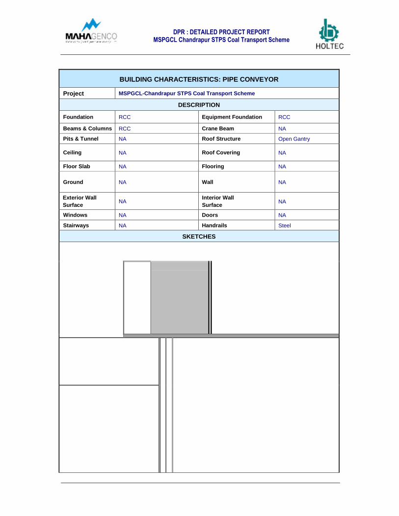
DPR : DETAILED PROJECT REPORTMSPGCL Chandrapur STPS Coal Transport Scheme
BUILDING CHARACTERISTICS: PIPE CONVEYOR
Project MSPGCL-Chandrapur STPS Coal Transport Scheme
DESCRIPTION
Foundation RCC Equipment Foundation RCC
Beams & Columns RCC Crane Beam NA
Pits & Tunnel NA Roof Structure Open Gantry
Ceiling NA Roof Covering NA
Floor Slab NA Flooring NA
Ground NA Wall NA
Exterior Wall
SurfaceNA
Interior Wall
SurfaceNA
Windows NA Doors NA
Stairways NA Handrails Steel
SKETCHES

DPR : DETAILED PROJECT REPORTMSPGCL Chandrapur STPS Coal Transport Scheme
BUILDING CHARACTERISTICS: TRANSFER TOWER AT PADMAPUR MINES
Project MSPGCL-Chandrapur STPS Coal Transport Scheme
DESCRIPTION
Foundation RCC Equipment Foundation Steel
Beams & Columns Steel Crane BeamMonorail for PipeConveyor
Pits & Tunnel NA Roof StructureCovered for openbelt conveyor & openfor pipe conveyor
Ceiling NA Roof Covering Corrugated Sheets
Floor Slab Steel Floor Flooring Chequered Plates
Ground NA Wall Side Cladded
Exterior Wall
SurfaceNA
Interior Wall
SurfaceNA
Windows NA Doors NA
Stairways Steel Handrails Steel
SKETCHES

DPR : DETAILED PROJECT REPORTMSPGCL Chandrapur STPS Coal Transport Scheme
BUILDING CHARACTERISTICS: WAGON LOADING HOPPPERS AT PADMAPURMINES
Project MSPGCL-Chandrapur STPS Coal Transport Scheme
DESCRIPTION
Foundation RCC Equipment Foundation Steel
Beams & Columns RCC Crane Beam Monorail for Conveyor
Pits & Tunnel NA Roof Structure Steel
Ceiling NA Roof Covering Corrugated Sheets
Floor Slab Steel Floor Flooring Chequered Plates
Ground NA Wall Storage Silos in Steel
Exterior Wall
SurfaceNA
Interior Wall
SurfaceNA
Windows Steel for Operator Cabin DoorsSteel for OperatorCabin
Stairways Steel Handrails Steel
SKETCHES
DPR : DETAILED PROJECT REPORTMSPGCL Chandrapur STPS Coal Transport Scheme
CHAPTER 1: TECHNICAL CONCEPT
TABLE OF CONTENTS
1. INTRODUCTION 1
2. EXCERPTS FROM TECHNICAL FEASIBILITY STUDY 1
3. DESIGN ASPECTS OF THE PROPOSED SYSTEM 2
3.1. PHYSICAL PROPERTIES OF MATERIAL 2
3.2. INPUTS CONSIDERATIONS FOR ELECTRICAL AND CONTROL DESIGN 2
3.3. INPUTS CONSIDERATIONS FOR CIVIL DESIGN 3
3.4. GENERAL SITE CONDITION 3
3.4.1. LOCATION 3
3.4.2. LOCAL CLIMATIC CONDITION 3
3.5. TOPOGRAPHY 3
3.6. GEOTECHNICAL INVESTIGATION 4
3.7. CAPACITY REQUIREMENT: 4
3.7.1. UTILITIES 5
3.8. CRITERION ADOPTED FOR SELECTION OF ELECTRO MECHANICAL MACHINERY 5
3.9. DUTY CONDITIONS 5
4. PROPOSED SYSTEM 5
4.1. PROPOSED ARRANGEMENT AT BHATADI MINES 6
4.2. PROPOSED ARRANGEMENT OF PIPE CONVEYOR CONVEYING 9
4.3. GENERAL ARRANGEMENT AT PADMAPUR MINES 14

DPR : DETAILED PROJECT REPORTMSPGCL Chandrapur STPS Coal Transport Scheme
5 . U T I L I T I E S A N D S E R V I C E S 1 8
5.1. WATER SUPPLY 18
5.1.1. FIRE FIGHTING SYSTEM. 19
5.1.2. DUST SUPPRESSION SYSTEM 20
6 . T E C H N I C A L S P E C I F I C A T I O N S 2 0
7 . I N S T A L L E D L O A D R E Q U I R E M E N T 2 5
8 . E L E C T R I C A L & I N S T R U M E N T A T I O N E N G I N E E R I N G 2 6
8.1. POWER SOURCES 26
8.2. POWER DISTRIBUTION & LOAD CENTRES 26
8.3. 33 KV SWITCHBOARD 27
8.4. 33! 6.6 KV POWER TRANSFORMERS 27
8.5. 6.6 KV SWITCHBOARDS 27
8.6. DC CONTROL POWER SUPPLY 27
8.7. 6.6 KV LOAD BREAK SWITCH 27
8.8. 6.6! 0.433 KV DISTRIBUTION TRANSFORMERS 27
8.9. LOW VOLTAGE 415 V DISTRIBUTION BOARD 28
8.10. POWER FACTOR IMPROVEMENT 28
8.11. 690V MOTORS 28
8.12. LOW VOLTAGE MOTORS 28
8.13. DRIVES 28
8.14. EARTHING ! LIGHTNING PROTECTION 28
8.15. LIGHTING 28
DPR : DETAILED PROJECT REPORTMSPGCL Chandrapur STPS Coal Transport Scheme
8.16. CABLE & CABLE LAYING 28
8.17. AIR CONDITIONING SYSTEM AND P&V SYSTEM 28
8.18. DOUBLE POLE STRUCTURE FOR 33KV/11KV/6.6KV/415V LINE 28
8.19. CONTROL & INSTRUMENTATON SYSTEM 28
8.19.1. GENERAL 28
8.19.2. PLANT CONTROL SYSTEM 28
8.19.3. CONTROL SCHEME 28
8.19.4. PROCESS INSTRUMENTATION 28
8.20. CLOSED CIRCUIT TV (CCTV) 28
8.21. FIRE DETECTION & ALARM SYSTEM 28
8.22. PLANT COMMUNICATION SYSTEM 28
8.23. UNINTERRUPTED POWER SUPPLY 28
9. CIVIL ENGINEERING CONSIDERATIONS 28
9.1. SITE CONDITION AND DESIGN CRITERIA 28
9.2. TOPOGRAPHY 28
9.2.1. SUBSURFACE CONDITION 28
9.2.2. GROUND WATER 28
9.2.3. CORROSION 28
9.2.4. SEISMICITY 28
9.2.5. WIND SPEED CONSIDERATION 28
9.2.6. PLANT STRUCTURES 28
9.2.7. STRUCTURAL DESIGN OF STORAGE STRUCTURES 28

DPR : DETAILED PROJECT REPORTMSPGCL Chandrapur STPS Coal Transport Scheme
9.2.8. LIVE LOADS 28
9.2.9. MACHINERY LOADS 28
9.2.10. DEFLECTION LIMITS FOR STRUCTURES 28
9.3. COMPONENT DESIGN CRITERIA 28
9.3.1. STORAGE STRUCTURES: 28
9.3.2. TRESTLES: 28
9.3.3. WATER TANKS: 28
9.3.4. SERVICE ROADS: 28
9.3.5. MATERIAL SPECIFICATION 28
9.3.6. BUILDING MATERIALS 28
9.4. DETAIL DESCRIPTION OF BUILDINGS & STRUCTURE 28

CHAPTER – 3
COST ESTIMATES

DPR : DETAILED PROJECT REPORTMSPGCL Chandrapur STPS Coal Transport Scheme
CHAPTER 3: COST ESTIMATES
1. INTRODUCTION
This chapter covers the estimates of investment for the installation of new coal transportsystem by pipe conveyor from Bhatadi mines to Padmapur mines.
The total investment cost estimated for the proposed mechanized material handling systemhas been explained as below:
2. COST CONSIDERATIONS
2.1 LAND & SITE DEVELOPMENT
Land and site development cost refers to the cost incurred in land or infrastructuraldevelopment of indirect component. For our project following will be required for land and sitedevelopment.
• Land acquisition by Mahagenco: Mahagenco will require land from private landowners and land from WCL for putting up this system. The cost for above have notbeen included in the cost estimates.
• Service road: A service road (dirt road) within shall be required as explained inChapter 2. The service road shall run along the whole length of pipe conveyorstarting from Bhatadi to Padmapur mines. This road shall be utilized for erectionduring project phase and maintenance after commissioning of the coal transportsystem.
• A lumpsum provision has been considered in cost for site preparation, grading andleveling.
2.2 BHATADI MINES
A belt conveyor, surge hopper and tail end of pipe conveyor will be installed in the Bhatadimines.
• The cost of mechanical equipment, electrical & instrumentation equipment, auxiliaryequipment & power distribution equipments etc. engineering work associated toequipments and freight charges shall be included for the equipments which are to beinstalled in Bhatadi mines.
• Civil & structures include the foundation & gallery of belt conveyors, surge hopperbuilding and platform thereof. Load centre 3, water tank/pump house has also beenaccounted for. Foundations and support required for tail end of pipe conveyor hasbeen considered under this cost head.
• Surge hopper, few platforms and structures have been envisaged in steelconstruction. Cost of the same has been included

DPR : DETAILED PROJECT REPORTMSPGCL Chandrapur STPS Coal Transport Scheme
• 100 m tar road has been considered which is linked with the existing metal road up tothe load center 03 located at Bhatadi mines.
• The execution of additional crusher installation shall be taken by up by WCLseparately, hence the above cost estimates do not include the cost of crushersystem.
• Since source of power at both the mines is not known, In view of this the cost ofpower distribution equipment/cable power has been considered within 200 mdistance of the substations indicated in the layout. Rest of the distribution fromsubstation to consumption points have been covered under cost estimates.
• Cost estimates for fire fighting system & dust suppression system has been workedout considering storage & distribution of water at both the mines. The source ofwater and providing water at the inlet of the tank at both the mines will be providedby Mahagenco. Cost of such connection has not been considered in the costestimates.
2.3 PIPE CONVEYOR (FROM BHATADI TO PADMAPUR MINES)
Pipe conveyor will run along the finalized route ( Route 1A) from Bhatadi mines to Padmapurmines.
• Cost of electromechanical equipments includes the cost of pipe conveyor,technological structures of conveyor, Walkway on conveyor, drives arrangement ofthe pipe conveyor including VFD and field instruments has been included in the costestimates.
• Cost of Civil support has been considered in RCC with bottom of gallery at 4 m level.At the road crossings it shall be 5.5/6m level from top of the road.
• Service road (Dirt road) of width 5m has been considered all along the length (approx5.6 KM) of the conveyor and its cost is included in the cost estimates.
• A small substation LC #2 has also been considered for lighting transformer atmidway of Bhatadi & Padmapur mines and cost of the same is included.
• For open portion of the conveyor, closed gallery in steel structure has beenconsidered in cost estimates.
• The conveyor also crosses 4 major water bodies as mentioned below:
o Erai river & two no Nallahs- Pipe conveyor walk way and structure with RCCcolumns in water is envisaged for crossing of these Erai/ Nallahs. The cost ofthe same is included in the cost estimates, but the connectivity across theriver/nallah for service road has not been considered in the cost estimates.
o Motghat Nallah: Since this is in vicinity of Padmapur mines a culvert hasenvisaged over this and its cost is included.

DPR : DETAILED PROJECT REPORTMSPGCL Chandrapur STPS Coal Transport Scheme
2.4 PADMAPUR MINES
At Padmapur mines the arrangement for wagon loading will be installed i.e. Head end of pipeconveyor in a transfer tower discharging to a belt conveyor and wagon loading hoppers will beinstalled in Padmapur mines.
• This includes cost of mechanical equipment, electrical & instrumentation equipment,auxiliary equipment & power distribution equipments etc.
• Transfer tower & wagon loading hoppers have been considered in steel as indicatedin the civil cost.
• Load centre 1, water tank/pump house has also been accounted for.
• About 100 m tar road from the existing roads of Mahagenco to the pipe conveyordrive unit has been considered.
• The concept for water and power availability remains same as explained for Bhatadimines.
3. ESTIMATE OF INVESTMENT
3.1. EPC COST
As explained in cost considerations above the following costs have been considered as EPCcosts i.e. which will be covered by EPC contractor.
o Electro-mechanical machinery
o The civil support structures required
o Bridges/culvert,
o Service road (WBM Dirt road)
The EPC cost of the project has been worked out as below:
INVESTMENT COST ESTIMATES- EPC COST
( In Rs Lakh unless Specified Otherwise )
Sno. Description Cost Remarks
1 BHATADI MINES
1.1 Electro-mechanical equipment including erection & freight 567.64
1.2 Civil
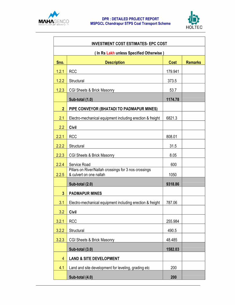
DPR : DETAILED PROJECT REPORTMSPGCL Chandrapur STPS Coal Transport Scheme
INVESTMENT COST ESTIMATES- EPC COST
( In Rs Lakh unless Specified Otherwise )
Sno. Description Cost Remarks
1.2.1 RCC 179.941
1.2.2 Structural 373.5
1.2.3 CGI Sheets & Brick Masonry 53.7
Sub-total (1.0) 1174.78
2 PIPE CONVEYOR (BHATADI TO PADMAPUR MINES)
2.1 Electro-mechanical equipment including erection & freight 6821.3
2.2 Civil
2.2.1 RCC 808.01
2.2.2 Structural 31.5
2.2.3 CGI Sheets & Brick Masonry 8.05
2.2.4 Service Road 600
2.2.5Pillars on River/Nallah crossings for 3 nos crossings& culvert on one nallah 1050
Sub-total (2.0) 9318.86
3 PADMAPUR MINES
3.1 Electro-mechanical equipment including erection & freight 787.06
3.2 Civil
3.2.1 RCC 255.984
3.2.2 Structural 490.5
3.2.3 CGI Sheets & Brick Masonry 48.485
Sub-total (3.0) 1582.03
4 LAND & SITE DEVELOPMENT
4.1 Land and site development for leveling, grading etc 200
Sub-total (4.0) 200

DPR : DETAILED PROJECT REPORTMSPGCL Chandrapur STPS Coal Transport Scheme
INVESTMENT COST ESTIMATES- EPC COST
( In Rs Lakh unless Specified Otherwise )
Sno. Description Cost Remarks
TOTAL EPC COST 12275.67
Say Rs 123 Crores.
Table: 3.1- Estimated Project Cost
The above cost estimates are net of Taxes and duties. The expected components ofTaxes shall be about 25% of the electro-Mechanical cost.
3.2. NON-EPC COST
The investment cost estimates which will be directly borne by Mahagenco are explained asunder
o Land acquisition by Mahagenco: Mahagenco will require land from private landowners and land from WCL for putting up this system. The cost for above have notbeen included in the cost estimates provided since cost of land is not known.
o The cost of re-routing of LT lines is a non-EPC cost and will be directly borne by theMahagenco. The same has been considered for rerouting of the 14 Low andmedium voltage power transmission lines amounting to approximately Rs 2.8Crores (considering average Rs 20 lakhs for each rerouting). The final estimation &execution of the rerouting job will be done by MSEB (Maharashtra State ElectricityBoard).
o Provision of pre-operative expenses have been considered as non EPC cost.
o A Route survey & geotechnical investigation being taken up by Mahagenco. Thiscost is a non-EPC cost and will be borne by Mahagenco directly.
o A lumpsum of Statutory approval required for the pipe conveyor installation has beenincluded in non –EPC project cost.
o The charges for consultancy and PMC services as indicated in project cost estimatesare not covered under EPC cost and hence is a non-EPC cost. Holtec has beenassigned only the design and engineering consultancy services for the coal transportsystem,
o The Project management of the project can be directly taken up by Mahagencopersonnel or alternatively a PMC services can be hired for close monitoring of the

DPR : DETAILED PROJECT REPORTMSPGCL Chandrapur STPS Coal Transport Scheme
project implementation. Cost for PMC services has not been included in costestimation.
NON-EPC cost has been worked out as presented in the table below:
INVESTMENT COST ESTIMATES- NON EPC
( In Rs Lakh unless Specified Otherwise )
Sno Description Cost Remarks
1 Land acquisition from private land owners ??
The same has not beenestimated as cost of landis unknown.
2 Preoperative Expenses 25
2 Design & Project Consultancy 55 Awarded to Holtec
3 PMC Consultancy Charges ??To be taken up by Mahagenco.
Being taken up by Mahagenco4 Soil Investigation ??
5 Topographical Survey ??
6 Statutory Approvals 30
7Cost of LT/MV lines rerouting @ Rs 20lakh per rerouting 280
TOTAL NON EPC COST 390The expenses on unknownportions to be added.
3.3. TOTAL PROJECT COST
Total project cost shall be the sum of EPC Portion, Tax components and cost towards NonEPC portion of the project.
4. ASSUMPTION FOR COST ESTIMATES
> The estimates of investment have been worked out based on assumption that project shallbe ordered in EPC mode.
> As soil investigation report is not available hence civil BOQ has been estimated on thebasis of soil bearing capacity provided by Mahagenco based on their previousexperience.
> Cost of land acquisition from private land owners/WCL has not been considered underproject cost.
> The cost estimates provided above do not cover provision for various taxes applicable onsupply & services.
> For the above estimates, power availability has been assumed within 200 m from theconsidered Load Centres. Water has been assumed as available till the water tanks atBhatadi as well as Padmapur.

DPR : DETAILED PROJECT REPORTMSPGCL Chandrapur STPS Coal Transport Scheme
> Other assumptions are covered under S No 2 & 3 above..
5. ESTIMATE OF INVESTMENT
The estimates of investment (for EPC portion of the cost) have been worked out based onconsultant experience, data base of similar project duly escalated/ prorated to match theselected material handling capacities and are to be understood with an accuracy range± 10%.
6. OPERATIONAL COSTS
Total operational cost of the coal transport system has been estimated as under:
OPERATIONAL COST
( In Rs Lakh unless Specified Otherwise )
S. No. Component
RemarksCost perannum
1Cost of Power @ 1.3 MWconsumed power 257.4
2Cost of operational spares @2 % of the EPC cost 246
3Pipe conveyor steel cord beltreplacement cost 115
4Cost of Operations (forconveying System) ??
5
Cost of operations (railtransportation fromPadmapur to CSTPS). ??
> The cost of power consumption has been calculated considering 12 hrs usage per day @500 tph for 330 days/annum. Assumed cost of power for estimation has been consideredas Rs 5/KWH.
> The cost of belt replacement has been calculated considering life of steel cord belt for 12KM of belting as 7 years. Cost/annum has been considered on prorata basis.
> Cost of spares, maintenance & lubrication etc have been calculated as lumpsum amountof 2 %/annum of EPC cost.
> Estimate of operating cost for Railway operations and conveying system operation &maintenance has not been made in above table. Manpower requirements for conveyoroperation has been covered under Chapter 4 of this report.

DPR : DETAILED PROJECT REPORTMSPGCL Chandrapur STPS Coal Transport Scheme
7. COST BENEFIT ANALYSIS (CBA)
Cost benefit analysis for the said project is non significant, due to the fact that suchinfrastructure project, are more for the reliability of transport system and hassles involvedwith road transportation rather than economical benefits.
Presently the coal is being handled by trucks. The benefits achieved by installing proposedconveying system are more qualitative in nature rather than quantitative, hence cannot bequantified in terms of monetary value.
Existing system of road transport leads to many operational problems. Same has beenexplained below
Multiple Handling of coal: The existing system involves a series of handling & transferpoints of coal. Multiple handling of any material leads to increase in cost and induces thehandling losses.
Safety Issues: A large fleet of trucks plying to CSTPS from Bhatadi Mines and vice versaincreases chance of accidents and loss of man & material. A mechanized system canpossibly reduce the risk of accidents due to movement of trucks.
Other Soft Factors:• Dependability on the contractors• Downtime due to sudden breakdown of vehicles• Inconsistency in the capacity of the transport system etc.• Tracking the incoming material flow to the plant
Environment Sustainability: Open dumping, crushing, multiple loading, and transportationin open trucks results into degradation of environment and justifies the installation of a totallyclosed conveying system i.e. pipe conveyor.
Poor maintenance by WCL: The maintenance of crushing plant in general is poor, resultinginto several lost hours. Hence a new additional crusher has been proposed, which shall beexecuted by WCL. The project also includes In Motion loading of railway wagons, as well asstorages at critical points for unhindered operation of the system.
In view of the advantages and benefits above the installation of mechanized coal transportsystem from Bhatadi mines to Padmapur mines and subsequent transport by existing railsystem is advisable.

DPR : DETAILED PROJECT REPORTMSPGCL Chandrapur STPS Coal Transport Scheme
CHAPTER 3: COST ESTIMATES
TABLE OF CONTENTS
1. INTRODUCTION 12. COST CONSIDERATIONS 12.1 LAND & SITE DEVELOPMENT 1
2.2 BHATADI MINES 12.3 PIPE CONVEYOR (FROM BHATADI TO PADMAPUR MINES) 2
2.4 PADMAPUR MINES 33. ESTIMATE OF INVESTMENT 3
3.1. EPC COST 33.2. NON-EPC COST 5
3.3. TOTAL PROJECT COST 64. ASSUMPTION FOR COST ESTIMATES 6
5. ESTIMATE OF INVESTMENT 77. OPERATIONAL COSTS 7
8. COST BENEFIT ANALYSIS 8

CHAPTER – 4
OPERATION & MAINTENANCE
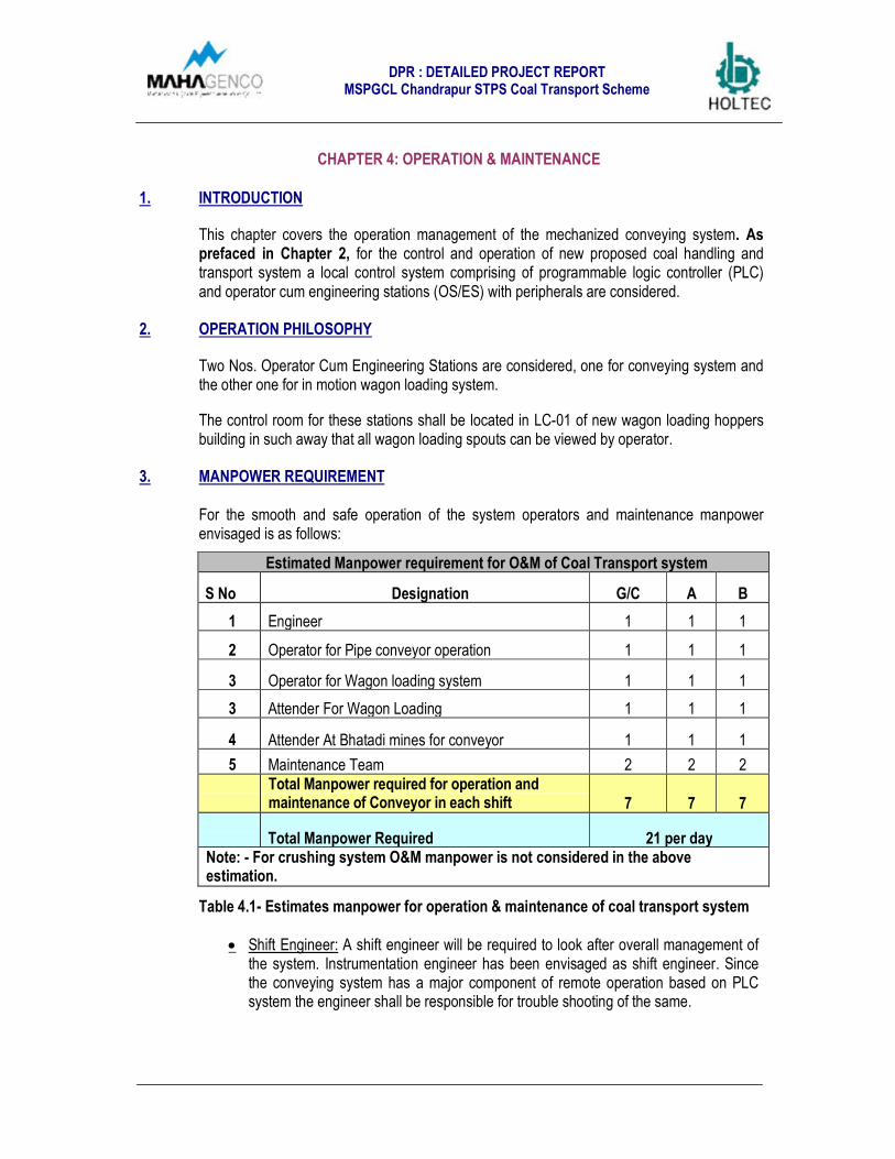
DPR : DETAILED PROJECT REPORTMSPGCL Chandrapur STPS Coal Transport Scheme
CHAPTER 4: OPERATION & MAINTENANCE
1. INTRODUCTION
This chapter covers the operation management of the mechanized conveying system. Asprefaced in Chapter 2, for the control and operation of new proposed coal handling andtransport system a local control system comprising of programmable logic controller (PLC)and operator cum engineering stations (OS/ES) with peripherals are considered.
2. OPERATION PHILOSOPHY
Two Nos. Operator Cum Engineering Stations are considered, one for conveying system andthe other one for in motion wagon loading system.
The control room for these stations shall be located in LC-01 of new wagon loading hoppersbuilding in such away that all wagon loading spouts can be viewed by operator.
3. MANPOWER REQUIREMENT
For the smooth and safe operation of the system operators and maintenance manpowerenvisaged is as follows:
Estimated Manpower requirement for O&M of Coal Transport system
S No Designation G/C A B
1 Engineer 1 1 1
2 Operator for Pipe conveyor operation 1 1 1
3 Operator for Wagon loading system 1 1 1
3 Attender For Wagon Loading 1 1 1
4 Attender At Bhatadi mines for conveyor 1 1 1
5 Maintenance Team 2 2 2Total Manpower required for operation andmaintenance of Conveyor in each shift 7 7 7
Total Manpower Required 21 per dayNote: - For crushing system O&M manpower is not considered in the aboveestimation.
Table 4.1- Estimates manpower for operation & maintenance of coal transport system
• Shift Engineer: A shift engineer will be required to look after overall management ofthe system. Instrumentation engineer has been envisaged as shift engineer. Sincethe conveying system has a major component of remote operation based on PLCsystem the engineer shall be responsible for trouble shooting of the same.

DPR : DETAILED PROJECT REPORTMSPGCL Chandrapur STPS Coal Transport Scheme
• Operartors: Two nos operator for (i) Conveying system & (ii) Wagon Loading systemhas been envisaged respectively. Both the operators will be responsible for operationof the system from control rooms.
• Attenders: Two nos attenders will be required. One attender will be required toensure the safe operation of the system at Bhatadi mines physically. One attenderwill look after wagon placement and proper loading operations at Padmapur mines.
• Maintenance Manpower: For maintenance of the system two personnel shall berequired. One fitter and one electrician will be enough for maintenance activities tobe performed.
• One dedicated maintenance vehicle comprise of all necessary electro mechanicaltools & tackles shall be required for regular maintenance and checking of pipeconveyor in every shift .The same has to be procured by Mahagenco .
4. MAINTENANCE:
The operation and maintenance can be taken up by Mahagenco directly by engaging theestimated manpower as mentioned above in Table 4.1 or alternatively AMC contractor canbe engaged for smooth operation of the system after commissioning.
Commissioning spares will be included in EPC contractor scope. Two years spares requiredfor operation has been envisaged as part of AMC contract.

\
CHAPTER – 5
EXECUTION SCHEDULE
DPR : DETAILED PROJECT REPORTMSPGCL Chandrapur STPS Coal Transport Scheme
CHAPTER 5: EXECUTION SCHEDULE
1. INTRODUCTION
This chapter covers the tentative time schedule envisaged for EPC contractor for activitiesinvolved in putting up mechanized coal transport system. Since the pipe conveyor of approx5.6 Km length is a long delivery items keeping in view of target date of commissioning, fasttrack execution of the project is foreseen.
1.1. EXECUTION STRATEGY
Typically any project has four core dimensions viz:
• Engineering: this directly impacts the smooth operations of the plant over its entire life.
• Procurement: is critical on account of its impact, on investment, performance as well aschoice of appropriate technology.
• Construction: is critical in terms of its impact on completion quality and the duration ofthe project phase.
• Project Management: other than its obvious impact on project timeliness, it alsocontributes to risk minimization for the promoter.
The basic engineering of the coal transport system is already over with DPR completion,now procurement will be next step in the line, the same will be based on the outcomes of theDPR.
Execution schedule for the EPC contractor has been worked out and has been annexed tothe report as Annexure 5.1.
2. PROJECT MANAGEMENT
Keeping in view of long delivery of pipe conveyor and its associated structure, project shallbe executed on a fast track So, in order to complete the project on time, EPC contractor hasto execute the jobs simultaneous at multiple locations, In view of the same A dedicated teamcomprise of minimum 5 persons as mentioned in the below table shall be deputed for thisproject to monitor the project on daily basis and also to keep check on the quality of workwhich shall be executed.
Mahagenco either shall directly engage the dedicated team mention in below table oralternatively the project management job can be offloaded to an external agency i.e. PMC(Project Management Consultancy) services can be hired from outside.
During tendering stage it shall further be discuss and taken up with EPC contractor, tosqueeze the delivery schedule and work out solution for timely delivery of the project asenvisaged by Mahagenco i.e. 10 months from zero date.
Zero date refers to the milestone of award of contract to the EPC contractor.

DPR : DETAILED PROJECT REPORTMSPGCL Chandrapur STPS Coal Transport Scheme
Estimated Manpower Required:
For the timely execution of the conveying system estimated manpower for PMC envisaged isas follows:
Estimated Manpower requirement for PMC for Coal Transport system
S No DescriptionNo of
personnel Duration in months
1 Resident Manager/Civil Engineer 1 10
2 Scheduling Engineer 1 10
3Billing/Structural engineer
1 12
3 Mechanical Engineer 1 8
4 E&I Engineer 1 6
TOTAL 5 48 man months
Note:- For crushing system PMC manpower is not considered in the aboveestimation.
Responsibility:-
Resident Manager/Civil Engineer: - He is primarily responsible for the completion of theproject on time without any delay, in addition to that he shall be responsible for all civil workand any critical issue which can make the delay shall be highlighted immediately toMahagenco.
Scheduling Engineer:- He shall prepare the detail project schedule in Primavera/Ms Projectas per the agreed time line and update the same on daily basis any critical path shall behighlighted and inform to avoid the delay. Also He shall be responsible for progress report.
Billing/Structural Engineer: - He is primarily responsible for checking of the bills raise by theEPC contractor and in addition to that he shall be take care of the entire steel structure work.
Mechanical Engineer: - He is primarily responsible for erection of each & every mechanicalequipment in addition he shall also be responsible for smooth commissioning of the system
Electrical Engineer: - He shall be responsible for erection of all E&I equipments in addition heshall also be responsible for smooth commissioning of the system.

ANNEXURE-1.1
MOM dated 10.12.2015
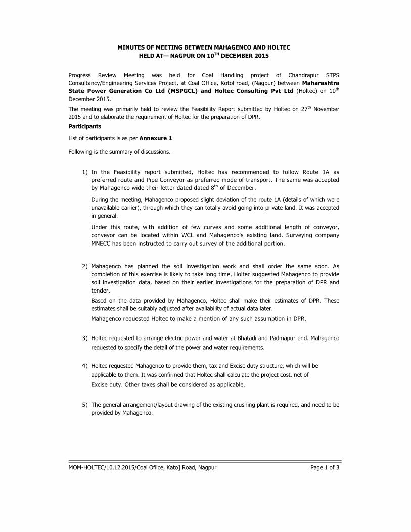
MINUTES OF MEETING BETWEEN MAHAGENCO AND HOLTEC
HELD AT— NAGPUR ON 10TH DECEMBER 2015
Progress Review Meeting was held for Coal Handling project of Chandrapur STPS
Consultancy/Engineering Services Project, at Coal Office, Kotol road, (Nagpur) between Maharashtra
State Power Generation Co Ltd (MSPGCL) and Holtec Consulting Pvt Ltd (Holtec) on 10th
December 2015.
The meeting was primarily held to review the Feasibility Report submitted by Holtec on 27th November
2015 and to elaborate the requirement of Holtec for the preparation of DPR.
Participants
List of participants is as per Annexure 1
Following is the summary of discussions.
1) In the Feasibility report submitted, Holtec has recommended to follow Route 1A as
preferred route and Pipe Conveyor as preferred mode of transport. The same was accepted
by Mahagenco wide their letter dated dated 8th of December.
During the meeting, Mahagenco proposed slight deviation of the route 1A (details of which were
unavailable earlier), through which they can totally avoid going into private land. It was accepted
in general.
Under this route, with addition of few curves and some additional length of conveyor,
conveyor can be located within WCL and Mahagenco's existing land. Surveying company
MNECC has been instructed to carry out survey of the additional portion.
2) Mahagenco has planned the soil investigation work and shall order the same soon. As
completion of this exercise is likely to take long time, Holtec suggested Mahagenco to provide
soil investigation data, based on their earlier investigations for the preparation of DPR and
tender.
Based on the data provided by Mahagenco, Holtec shall make their estimates of DPR. These
estimates shall be suitably adjusted after availability of actual data later.
Mahagenco requested Holtec to make a mention of any such assumption in DPR.
3) Holtec requested to arrange electric power and water at Bhatadi and Padmapur end. Mahagenco
requested to specify the detail of the power and water requirements.
4) Holtec requested Mahagenco to provide them, tax and Excise duty structure, which will be
applicable to them. It was confirmed that Holtec shall calculate the project cost, net of
Excise duty. Other taxes shall be considered as applicable.
5) The general arrangement/layout drawing of the existing crushing plant is required, and need to be
provided by Mahagenco.
MOM-HOLTEC/10.12.2015/Coal Ofiice, Kato] Road, Nagpur Page 1 of 3

MSPGCL M/s, HOLTEC
1) Shri. A.G.De Nagpur 1) Shri. J.P.Gupta, Chiet General Manager
MINUTES OF MEETING BETWEEN MAHAGENCO AND HOLTEC
HELD AT — NAGPUR ON 10TH DECEMBER 2015
6) Once the details / confirmations are made available, Holtec shall submit DPR in about 10 days
time. As per the present situation, it is expected that all the requirements as detailed in
this MOM shall be met by 20th of December, so that DPR could be submitted by 30th of
December.
Mahagenco shall also provide the standard formats of GCC and SCC (general and special
conditions of Contract) they follow for open tendering.
2) Shri. A.K.Chandragade, Dy. C.E.(T, I & CI), Nagpur
3) Shri. V.K.Dongre, Dy.(!(Civil, 2x500 MW), Chandrapur Project
4) Shri. M.K.Natoo, S.E.(P&P), Head Office, Mumbai
MOM-HOLTEC/10.12.2015/Coal Nice, Nato! Road, Nagpur Page 2 of 3

MINUTES OF MEETING BETWEEN MAHAGENCO AND HOLTEC
HELD AT — NAGPUR ON 10TH DECEMBER 2015
Annexure 1:
MSPGCL:
Shri. C.S.Thotwe, Director (Project)
Shri. A.R. Nandanwar, Executive Director (Project)
Shri. A.G.Deotare, C.E.(Civil-II), Nagpur
Shri. V.K.Dongre, Dy.C.E.(Civil, 2 x 500 MW), Chandrapur Project
Shri. A.K.Chandragade, Dy.C.E.(T, I & C), Nagpur
Shri. M.K.Natoo, S.E.(P&P), Head Office, Mumbai
M/s, Holtec , New Delhi
Shri. J.P. Gupta, Chief General Manager
M/s, DCPL, Kolkata
Shri. Sandeepan Ghosh
Shri. Asim Nath
MOM-HOLTEC/10.12.2015/Coal Office, Katol Road, Nagpur Page 3 of 3

ANNEXURE – 2.1
Layout Pipe Conveyor- ROUTE IA

A B C D E F G
H'ON aIC
I, 0 -Z0-00-0tgg I.- Pc' N./4 ---- F IN DOUBTASK= 318535.54
BELT CONVEYOR
Y = 2218806.29/9 ,Q0......., TP-2
OFFICE
= 318899.03OFFICZom,
...... ,,,, = 2219130.23PETROL PUMPOFFIr .140 TP-0
4000 zgO121.........-(COAL STORAGE SILO) ip.DA,,,,,,irrog .--,/ 4X=318545.23 la-----r4-Ow-Pa...y.c_,,--vo.....,nall RCCROUND N.G.L. CONVEYORGALLERY REMARKS„r„, 'Y = 2219064.16 ,...,...,aIIIX,101 COLUMNNos. oarnaLGROUNDuve.) BOTTOM LEVEL
a.....-...,- *).3.6.- -_,3,--c------
1 193.29 197.251
_~ir® TP-1.v_PO
2 192.99 197.46
ELECT.ROOM LC-3 it5B111210
allierdC1,........--""' ,,,,..,,,, . !-oo 3 193.06 197.63
10111111 ' 4 192.98 197.80
TcLerla,s,......01,%.
.` 4.51.......,.......... '42 s,...,0,....
56 119922..9987198.48
le= -1.11Virial
is J1 i 199.16 METAL ROAD CROSSING1111!
& WEIGHT BRIDGE X = 318467.58 7 193.23 199.16zs
1 x13 8 192.91 198.97Y = 2218693.05 u
BOUNDARYIill
9 192.95 198.79
2 TP-3 io 192.81 198.61 2 -II ii 192.63 198.43
Ili 12 192.49 198.25
T. 13 192.39 198.07
14 192.26 197.89illi 1 15 119922..0142 11 9977..5731
II 1156
17 191.88 197.35
1 cL-192.02N. 18 191.77 197.17
M.i6
19 191.70 196.98- _ 20 191.59 196.80
STORE OFFICE 21 191.49 196.62
22 191.39 196.44
..., 23 191.29 196.26
Ili 24 191.17 196.08STORE •FFICE
3 25 190.99 195.90 3
L.,..k - , 418
26 190.82 195.72
27 190.64 195.54
o 28 190.52 195.36
4
,
. .STORE OFFICE
1o ....011111
1114Ilk
..:,41_,_o'
ETAL ROAD
..<,....,©itp
4 a i = 318535.54o
GL-191.390 4
'II Y = 221 8806.29id 800
n TP-2 B-si-9., . . ;17 iiH11Ali I
,„0 800At !1771 ii% %CRONIVELIMMO, 1 ,......,, - ' BIIINC.,z--741 1, 1
4\r EJ,-,, _ _ 0 RCC ROUND COLUMN RCC ROUND COLUMN1711 CO RCA.,11
1 i$- ..OR QUM/ VIIII. CAT LADDER
RCC ROUND COLUMN
EEMIR LEVEL
RCC ROUND COLUMN Ixay\
>Am\EN-
TYPICAL ARRGT. OF
Agg
SECTION B-B
5 PIPE CONV. GALLERY 504 .0.0 -1 '''')
______________________ Am,
TYPICAL ARRGT.
Atittx.A ,xitt,
OF PIPE CONY. GALLERY AT ROAD
zmitk,
CROSSING SECTION A-A
GL
-190.52
REV 01 DATE 04 DATE 0 24.12.15 --- JPG
CONCURRENCE REV DATE ISSUED FOR BY
THIS DESIGN AND DRAWING IS THE
SOLE PROPERTY OF HOLlEC1
2
DO NOT SCALE, WORK TO DIMENSIONS ONLY.
FOR TOLERANCES REF. HOLTEC STD. DRG. NO. Al -HOL-STD-1-129.
ALL
DIMENSIONS
ONLY THE LATEST VERSION OF THIS DRG. AS INDICATED IN REVISION COLUMN IS VALID.
THE PREVIOUS DRG. SHALL BE MARKED SUPERSEDED AND REMOVED FROM SITE OF WORK.HOLTEC CONSULTING PRIVATE LIMITED
ICONSUL] ING (P) DD. & COPYRIGHT
OF 11 REMAINSW11HHODEC.11
INHOLTEC CENTRE, A BLOCK, SUSHANT LOK, SURBAON-1 22001 HARYANA, INDIA
SHOULD BE TREATED AS STRICTLY
CONFIDENTIAL AND MUST NOT BE CUSTOMER MAHARASHTRA STATE POWER GENERATION CO.LTD.6REPRODUCED, COPIED, LOANED OR MILLIMETRES DES. mc DEC-15 PROJECT :15540,CHANDERPUR CAD FILE : 15540000201R0
5
DISPOSED DIRECTLY EVEN IN PAR1
NOR USED FOR ANY PURPOSE DRN. GKR 05.12.15 ARRANGEMENT FOR POPE CONY.OTHER THAN FOR WHICH IT IS
UNLESS CHKD.RNC 10.12.15SPECIFICALLY FURNISHED WITHOUT
THE PRIOR WRIll EN CONSENT OTHERWISE APPD. JPG 10.12.15of 6()
DRG.NO. -15Sh-1OF HOLlEC CONSULTINGPRIVATE REFERENCE NO. DETAILS SPECIFIED REV No DATE BY CHKD APPD. DETAILS Al 540-00-02-01 REV.
LIMIlED R EF ER ENC ES NOTES R EV IS I 0 NSSCALE : 1:000
0
A B C D E F G H

A B C D E F G H
I, 0-Z0-00-0tgg I,- Pc' 'ON 'alC IF IN DOUBTASK
29 190.47 195.17
= 30 190.48 194.99
= 31 190.47 194.81
0 32 190.41 194.63
33 190.33 194.45
1o.6= 34 190.21 194.27
GL 90.47 ---), 35 190.07 194.09
`o67, 36 189.93 193.91
EE 1714 37 189.80 193.73== - L Ei7, 38 189.65 193.73
GL-190.48 :bo 39 189.65 193.73
66 X = 318445.96 40 189.65 193.69
.-, Y = 2217822.55 41 189.65 193.64
___. L-190.47 TP-4 42 189.67 193.59
3 25000 43 189.65 193.54
6625000 25000 44 189.62 193.49
= 250008 25000 e 45 189.57 193.44GL 90.41 25000 e 46 189.49 193.39
oit 2500025000 25000 47 189.42 193.34
= 48 189.35 193.29= 49 189.32 193.29
2 GL-190.330 250 189.32 193.29
40
R int. Km, 51 189.32 193.29
52 189.30 193.29
GL-190.21 53 189.25 193.290
54 189.20 193.29
o= 55 189.19 193.29
' 56 189.22 193.29
57 189.26 193.29
58 189.30 193.29== 59 189.34 193.29
GL-189.93 60 189.37 193.29
61 189.35 193.29
62 189.29 193.29
H , 63 189.24 193.20GL
-189.80 64 189.31 193.10
3 65 188.99 193.00 3
=, 66 188.80 192.90
GL 89.654 67 188.66 192.80
68 188.50 192.70
L-189.65814448 69 188.32 192.61
70 188.11 192.51
71 187.88 192.41
N L-189.650 72 187.62 192.31
73 187.36 192.21
74 186.04 192.11Gl-189 ssg 00 25000 75 186.58 192.01
76 186.34 191.9225000 2520
i 77 186.20 191.8225000
189.61
®788 25000 185.36 191.72
25000 79 184.84 191.6225000
25000 80 184.55 191.52 NALA CROSSING4 25000
\VO@9 4 . . . . .
2 5 0 0 0 81 184.97 191.4225000 82 185.53 191.33
5000e 25000 e 83 186.16 191.23
V '1'*'1 ¢¢200
25000 r' 84 186.44 191.13
5
GV 189''
0
189
g.
#
EINE
25000
27.
s9
5.,,2
0
REV 01 DAIS 04 DAIS 0 24.12.15 --- JPG
CONCURRENCE REV DATE ISSUED FOR BY
THIS DESIGN AND DRAWING IS THE
SOLE PROPER-1Y OF HOLTEC
1
2
DO NOT SCALE, WORK TO DIMENSIONS ONLY.
FOR TOLERANCES REF. HOLTEC STD. DRG. NO. Al -HOL-STD-1-129.
ALL
DIMENSIONS
ONLY THE LATEST VERSION OF THIS DRG. AS INDICATED IN REVISION COLUMN IS VALID.
THE PREVIOUS DRG. SHALL BE MARKED SUPERSEDED AND REMOVED FROM SITE OF WORK. HOLTEC CONSULTING PRIVATE LIMITEDCONSULTING (P) LLD. & COPYRIGIR
OF IT REMAINS WI11-1 HOLTEC. IT INHOLTEC CENTRE, A BLOCK, BUSHANT LOK, BURBAON-122001 HARYANA, INDIA
SHOULD BE TREATED AS STRICTLYCONFIDENTIAL AND MUST NOT BE CUSTOMER MAHARASHTRA STATE POWER GENERATION CO.LTD.
6
REPRODUCED, COPIED, LOANED OR MILLIMETRES DES.RNC DEC-15 PROJECT : 15540,CHANDERPUR
:CAD FILE 1554000020160
6
DISPOSED DIRECTLY EVEN IN PAHL
NOR USED FOR ANY PURPOSEDRN. GKR 05.12.15 ARRANGEMENT FOR POPE CONV.
OTHER THAN FOR WHICH IT IS
UNLESS CHKD NC 10.12.15
SPECIFICALLY FURNISHED WITHOUT
l HE PRIOR WRIll EN CONSENTOTHERWISE(Sh-2 APPD. JPG 10.12.15 of 6)
OF HOLTECCONSUL) ING PRIVATE REFERENCE NO. DETAILS SPECIFIED REV No DATE BY CHKD APPD. DETAILSAl
DRG.NO. -15540-00-02-01 REV.
LIMITED R EF ER ENCES NOTES R E V IS IONSSCALE I 1:000
0
A B C D E F G H

A B C D E F G H
I, 0-Z0-00-0tgg I,- Pc' 'ON 'alC IF IN DOUBT ASK85 186.57 191.03
86 186.58 190.93
87 186.60 190.8825000
88 186.71 190.78
1,6 89 186.82 190.78.87•
1 90 186.97 190.78
91 186.91 190.78
14 92 186.91 190.7893 186.92 190.78------
6,"•Nr.Alliiii*„ .57 94 186.88 190.78
...Ale 95 186.81 190.78
96 186.80 190.78
'''', 97 186.79 190.78
98 186.77 190.78
® 99 186.76 190.78
. 100 186.71 190.82
101 186.64 190.87%
Sb.. 102 186.61 190.91
103 186.56 190.96
\ 104 186.53 191.00105 186.51 191.04
BOUNDARY OF BHATADI 0/C MINE oh2 \
106 186.51 191.092 -
107 186.51 191.13
108 186.51 191.18
109 186.53 191.22
# .. 110 186.50 191.27
111 186.46 191.31• 112 186.41 191.36
, 113 186.35 191.40
‘ 114 186.29 191.45
115 186.21 191.49
\ \ 116 186.29 191.54
117 186.47 191.5800 118 186.23 191.63 ASP ROAD
CROSSING1\6, O 119 185.63 191.63
120 184.76 191.63
3 121 184.10 189.86 3
\ 122 183.64 188.10
‘ 123 183.15 188.10
O 124 182.80 188.10
% \ 125 182.78 188.1011
1\p, 126182.50 188.10
co 127 181.88 188.10 NALA CROSSING0 )..
‘
V. 2
11298 183.03182'398
11888..110°
0 130 182.94 188.10
m0 182.41 188.10
ab
‘
,,,,,,„,„„,
4 11S1. %
, O
\ \
0
,0,....1111
Illtii
\i ,
4
o ,,,,,,,,,, ...,`ARV OF
5 BOUND illSto.
,
\
A, 5
EL
\g6AbREV 01 DATE 04 DATE 0 24.12.15 --- JPG
CONCURRENCE REV DATE ISSUED FOR BY
THIS DESIGN AND DRAWING IS THE
SOLE PROPERTY OF HOLlEC1
2
DO NOT SCALE, WORK TO DIMENSIONS ONLY.
FOR TOLERANCES REF. HOLTEC STD. DRG. NO. Al -HOL-STD-1-129.
ALL
DIMENSIONS
ONLY THE LATEST VERSION OF THIS DRG. AS INDICATED IN REVISION COLUMN IS VALID.
THE PREVIOUS DRG. SHALL BE MARKED SUPERSEDED AND REMOVED FROM SITE OF WORK. HOLTEC CONSULTING PRIVATE LIMITEDCONSULTING (P) L10. & COPYRIGH1
OF IT REMAINS WIl H HOLl Ea IT INHOLTEC CENTRE, A BLOCK, ELISHANT LOK, BURBAON-122001 HARYANA, INDIA
SHOULD BE TREATED AS STRICTLY
CONFIDENTIAL AND MUST NOT BE CUSTOMER MAHARASHTRA STATE POWER GENERATION CO.LTD.6
REPRODUCED, COPIED, LOANED OR MILLIMETRES DES. RNC DEC-15 PROJECT : 15540,CHANDERPUR CAD FILE : 15540000201606
DISPOSED DIRECTLY EVEN IN PART
NOR USED FOR ANY PURPOSE DRN. GKR 05.12.15 ARRANGEMENT FOR POPECONY.OTHER THAN FOR WHICH IT IS
UNLESS CHKD.RNC 10.12.15SPECIFICALLY FURNISHED WITHOUT
1HE PRIOR WRIll EN CONSEN1OTHERWISE APPD. JOG 10.12.15 (Sh-3 of 6)
OF HOLlEC CONSUL] ING PRIVATE REFERENCE NO. DETAILS SPECIFIED REV No DATE BY CHKD APPD. DETAILSAl
DRG.NO. -15540-00-02-01 REV.
OWED R EF ER ENCES NOTES R EV IS IONSSCALE I 1:000
0
A B C D E F G H

A B C D E F G H
I, 0-Z0-00-0tgg I,- Pc' 'ON 'alC IF IN DOUBTASK132 182.38 188.10
0 133 182.75 188.10
134 183.72 188.10
135 182.01 188.10Q
0c,,,,, 136 179.47 188.10
1 0,.. .1pb 137 178.93 188.10 ERAI RIVER CROSSING
0 / 138 179.07 188.10-tcja. Q0 0 139 181.53 188.10
0. I,
140 182.68 188.10. "?ix 141 183.08 188L 0
= 142 183.23 188.10..1.110
tillt., 143 183.29 188.10
144 183.50 188.10
® 145 183.89 188L 0
bbpc. 146 184.36 188A0
.,..k...4 ,.. •..... 147 184.77 188.710 148 185.19 189.02
149 185.61 189.32
150 185.93 189.63
151 186.14 189.94152 186.25 190.25
2
0 19' 153 186.35 190.212 -
Ne 154 186.40 190.17ii\ik
\ 155 186.45 190.13
,.12` 156 186.46 190.09
..or 157 186.46 190.05akr""
&Au. 158 186.46 190.01
P.1 159 186.41 189.971\4\Os°)0 160 186.22 189.93
0 161 186.06 189.89
162 185.97 189.85
163 185.89 189.81
164 185.76 189.77D'au,,,by +0,
165 185.76 190.04
166 185.76 190.31
167 185.78 190.5831, 0 68 185.84 190.86
3
\ 169 185.88 191.13It* 170 185.88 191A0
= 2216569.94TP-6
°o0
9,
O \
O°
4
800 A 800
4
CM IrLawl ,,.,1 k ':,' EP r'il..y ....,..,,,.... ...ao.,,a,.... ',-=,,,,.a0T 7,I. .....p.
QORCC ROUND COLUMN RCC ROUND COLUMN
0.,(GGL)
`'s00,
,:.c.()dmv
25000_________ 5 '90 WO SECTION A-A 5
A
v(1'5" TYPICAL ARRGT. OF PIPE CONV. GALLERY AT RIVER/NALA CROSSING
0
REV 01 DAIS 04 DAIS 024.12.15 --- JPG
CONCURRENCE REV DATE ISSUED FOR BY
THIS DESIGN AND DRAWING IS THE
SOLE PROPERTY OF HOLlEC1
2
DO NOT SCALE, WORK TO DIMENSIONS ONLY.DOFOR TOLERANCES REF. HOLTEC STD. DRG. NO. Al -HOL-STD-1-129.
ALL
DIMENSIONS
ONLY THE LATEST VERSION OF THIS DRG. AS INDICATED IN REVISION COLUMN ISVALID.
PREVIOUS DRG. SHALL BE MARKED SUPERSEDED AND REMOVED FROM SITE OF WORK.HOLTEC CONSULTING PRIVATE LIMITED
CONSDLENG (P) LED. & COPYRIGH1
OF IT REMAINS WIl H HOLl EC. IT INHOLTEC CENTRE, A BLOCK, SLISHANT LOK, BURBAON-I 22001 HARYANA, INDIA
SHOULD BE TREATED AS STRICTLY
CONFIDENTIAL AND MUST NOT BE CUSTOMER MAHARASHTRA STATE POWER GENERATIONCO.LTD.6
REPRODUCED, COPIED, LOANED OR MILLIMETRES DES. RNC DEC-15 PROJECT : 15540,CHANDERPUR:
CAD FILE 1554000020160
6
DISPOSED DIRECTLY EVEN IN PAR1
NOR USED FOR ANY PURPOSEDRN. GKR 05.12.15 ARRANGEMENT FOR POPE CONV.
OTHER THAN FOR WHICH IT IS
UNLESS CHKD NC 10.12.15SPECIFICALLY FURNISHED WITHOUT
1HE PRIOR WRITTEN CONSEN1OTHERWISE APP D. JPG 10.12.15
(S h -4 of 6
OF HO= CONSUL] ING PRIVATE REFERENCE NO. DETAILS SPECIFIED REV No DATE BY CHKD APPD. DETAILSAl
DRG.NO. -15540-00-02-01 REV.
DATED R EF ER ENCES NOTES R EV IS IONSSCALE I 1:009
0
A B C D E F G H

A B C D E F G H
I, 0-Z0-00-0tgg I,- Pc' 'ON 'alC IF IN DOUBT ASK171 185.95 191.67 186 187.53 191.95172 186.97 191.95 187 188.00 191.95
173 186.85 191.95 188 187.55 191.95
174 186.56 191.95 DRAIN CROSSING 189 187.41 191.95
175 186.77 191.95 DRAIN CROSSING 190 187.33 191.95
1 0 .9
5 176 187.61 191.95 191 187.24 191.95
2s0 177 187.62 191.95 192 187.24 191.95dG
0 178 187.80 191.95 193 187.25 191.95
179 188.14 191.95 194 187.20 191.95
DSO 180 188.36 191.95 195 187.16 191.95
1\900 181 188.07 191.95 220KV HT LINE CROSSING 196 187.07 191.95
182 188.08 191.95 197 187.07 191.95
\ 183 188.06 191.95 198 187.25 191.95
® 184 188.89 191.95 199 187.43 191.95
185 188.28 191.95 200 187.68 191.95
\ , 201 187.90 191.95HOUS # \ ST « o 0 202 187.99 191.95
203 187.97 191.95
' . 4,Alikkksp11111k
204 187.95 191.95
4,.. 205 187.92 191.95206 187.88 191.95
2 Iii. .lr 207 187.80 191.95
2 -
208 187.63 191.95
\ 209 187.49 191.62
210 187.07 191.08 220KV HT LINE CROSSING
HOUSE 211 185.83 190.53
\ 212 185.41 189.99
\ °,2
0
, ,
\ o
O o1
3o
3
OA
lfe
t)
o
L....... 1111111111 .7...,
1 PPI Cw - 1P -
10°'
I I10II IIII I .- -- ' - . .------= 2215641.88
TP-7
BOUNDARY OF MAHAGENCO
5 = 321156.99 8 Qz 0 5
Y=2215601.68 0 wz..2 a
TP -8 2= <‹ 2
LL0 a-
0
REV 01 DATE 04 DATE 0 24.12.15 --- JPGCONCURRENCE REV DATE ISSUED FOR BY
THIS DESIGN AND DRAWING IS THE
SOLE PROPERTY OF HOLlEC1
2
DO NOT SCALE, WORK TO DIMENSIONS ONLY.
FOR TOLERANCES REF. HOLTEC STD. DRG. NO. Al -HOL-STD-1-129.
ALL
DIMENSIONS
ONLY THE LATEST VERSION OF THIS DRG. AS INDICATED IN REVISION COLUMN IS VALID.
THE PREVIOUS DRG. SHALL BE MARKED SUPERSEDED AND REMOVED FROM SITE OF WORK. HOLTEC CONSULTING PRIVATE LIMITEDCONSOLING (P) DD. & COPYRIGH1
OF IT REMAINS WIl H HOD EC. IT INHOLTEC CENTRE, A BLOCK, SUSHANT LOK, BURBAON-I 22001 HARYANA, INDIA
SHOULD BE TREATED AS STRICTLY
CONFIDENTIAL AND MUST NOT BE CUSTOMER MAHARASHTRA STATE POWER GENERATION CO.LTD.6
REPRODUCED, COPIED, LOANED ORMILLIMETRES DES. RNC DEC-15 PROJECT : 15540,CHANDERPUR
:CAD FILE 1554000020160
6
DISPOSED DIRECTLY EVEN IN PART
NOR USED FOR ANY PURPOSE DRN. GKR 05.12.15 ARRANGEMENT FOR POPE CONY.OTHER THAN FOR WHICH IT IS
UNLESS RNC 10.12.15SPECIFICALLY FURNISHED WITHOUT
1HE PRIOR MAVEN CONSENT OTHERWISE APPD. JPG 10.12.15(Sh -5 of 6)
OF HOLlEC CONSOLING PRIVATE REFERENCE NO. DETAILS SPECIFIED REV No DATE BY CHKD APPD. DETAILSAl
DRG.NO. -15540-00-02-01 REV.
OWED R EF ER ENCES NOTES R E V IS IONSSCALE I 1:000
0
A B C D E F G H

A B C D E F G H
I, 0-Z0-00-0tgg I,- Pc' 'ON 'alC IF IN DOUBTASK
213 184.96 189.45
214 184.91 188.91
215 184.58 188.19
as,
. 216 183.71 187.50
1 217 182.67 187.50
218 181.64 187.50 MOTGHATNALACROSSING
219 181.75 187.50 (PROPOSED CULVERT)
220 183.45 188.45
0-p 221 183.98 189.61
222 184.61 190.72PROPDSED t.9AT morn uLVERT
®GHAT _06NALA .-- o-
25000 (30
•
29 256
EXT. MGR PADMAPUR.
'--t.,,,
0,4 '0';
2 2 -
° - -- _ _ 64(9 136T CONVEYOR
END POINTMGR PADMAPUR
..
zi4-,,,,,-, 1.21.8c2
`Q.
Lavifift. .II,
,T --`--••• Ilitt 11 .....' ,-, ""'"'"---------kroe, ......11 1 ELECT.ROOM LC-1.:0 o .....
3 z
225z - - <4 ie.ketP (WAGON LOADING SYSTEM)24000 '-'
OA X = 321833.07i 3
i 2 X = 321690.26 &E-r co, 01 ., Valt = 2215588.56
r 0Li cc
..?( i1
0 11-
ii t• st >-0
, '321827. °.r Y= 221562.75 ,---22/559/ 2 T.P -1 0
TRANSFER TOWER) . ,,,,,o.
7°
S 0Z
ca 7 -1).D800 i 800
/- , - -
..,.\ .. \ f'ii I 10
!r_71 A
V _1 LJ 7;011MR MUMOFPI'S _0.y 60170M LE. RCC ROUND COLUMN
J~OV10 RCC ROUND COLUMN
4 '45 0'3 \
EM PAIII
5010
k?
2
4
T.O. ULVER7.j,(7.0.ROA,
1 '7.0. CUL.27ix,) (7.0. Iii.).., L WIDE ROAD I
I
CI-c.1 EEM
-------------------------------------------------
22000 5500
27000SECTION D-Da i+D
TYPICAL ARRGT. OF PIPE CONY. GALLERYAT MOTGHAT CULVERT
5 5
0
REV 01 DAIS 04 DAIS 0 24.12.15 --- JPGCONCURRENCE REV DATE ISSUED FOR BY
THIS DESIGN AND DRAWING IS THE
SOLE PROPERTY OF HALTED
12
DO NOT SCALE, WORK TO DIMENSIONS ONLY.FOR TOLERANCES REF. HOLTEC STD. DRG. NO. Al -HOL-STD-1-129.
ALLDIMENSIONS
ONLY THE LATEST VERSION OF THIS DRG. AS INDICATED IN REVISION COLUMN IS VALID.
THE PREVIOUS DRG. SHALL BE MARKED SUPERSEDED AND REMOVED FROM SITE OF WORK.HOLTEC CONSULTING PRIVATE LIMITED
ICONSULENG (P) LEE & COPYRIGHT
OF IT REMAINS WIl H HOLl EC. IT INHOLTEC CENTRE, A BLOCK, SLISHANT LOK, OURBAON-122001 HARYANA, INDIA
SHOULD BE TREATED AS STRICTLY
CONFIDENTIAL AND MUST NOT BE CUSTOMER MAHARASHTRA STATE POWER GENERATION CO.LTD.6
REPRODUCED, COPIED, LOANED OR MILLIMETRES DES.RNC DEC-15 PROJECT :15540,CHANDERPUR
ICAD FILE 1554000020190
6
DISPOSED DIRECTLY EVEN IN PART
NOR USED FOR ANY PURPOSEDRN. GKR 05.12.15 ARRANGEMENT FOR POPE CONY.
OTHER THAN FOR WHICH IT IS
UNLESS CHKD NC 10.12.15SPECIFICALLY FURNISHED WITHOUT
1HE PRIOR WRIll EN CONSEN1OTHERWISE(S APPD. JPG 10.12.15
h -6 of 6)
OF HOLlECCONSULTING PRIMA] E REFERENCE NO. DETAILS SPECIFIED REV No DATE BY CHKD APPD. DETAILSAl
DRC.NO. -15540-00-02-01 REV.
LIMIlED R EF ER ENCES NOTES R E V IS IONSSCALE I 1:000
0
A B C D E F G H

ANNEXURE – 2.2
SINGLE LINE DIAGRAM

3 3 K V 0 / H L I N E 3 3 K V 0 / HL I N E DADAMPUR
-(41-\\800A
30KV,10KA- i -EEl
LA
30KV,10KA
LA800A
MSEBMETERIN 41sraN...,...4
1,
MSEBMETERINGPT
CT300/1ACL 0.2, 10VA
.421: 3.1<,y1eilc)V \
i CLIENT'S SCOPE
PTCT300/1ACL 0.2, 10VA
/
800A 8°°AN CLIENT'S SCOPE /
33KV CABLE
33KV CABLE BIDDER'S SCOPE 33KV ICOG -
BIDDER'S SCOPE 33KVICOG - r PANEL
y PANELAT LC-3
PT
,zo-
CT300/1-1-1A
./.•-, 33kV /110V/110V
Ts / J3 / \ IS
1250A
=.
30KV,10KA
AT LC-1PT
,zi
CT300/1-1-1A
33kV /110V /110V.°- Tr./\73./TS
ill 1250A
=.
30KV,10KA
ERLA
LA ' 33KV CABLE •. .
33KV CABLE • Am 2.5MV
100A t NGR=
MPI,ilall
A2.5MV33/6.6KVONANTRF. WITH
OLTC
100A,_
,, V-10,4 ft1/1
NGR
"""33/6.6KVONANTIRF.WITHOLTC
V
v 6.6KV SWITCH BOARD6.6/v3Kv1 1 o/v3v/i 10 la/
30VA, CL-0.5 & CL-3P6.6/V3KV/110/V3V/11018V SILO EXTRACTION
6.6KV SWITCH BOARD 30VA, CL-0.5 & CL-3P • 10- )-1-1".-
COAL HANDLING ELE. ROOM (LC-1)
ELE. ROOM (LC-3)• 0 )-1-1-- 300/1A, CL- 30VA, -• METERING
0 .5300/1A, 30VA,
CL-0.5
300/1A, 30VA, ==.CL-5P10
1250A6.6KV '
-• METERING
PROTECTION
N 0
300/1A,30VA,==.CL-5P10
1250A,6.6KV
6.6KV, 630A,
PROTECTION
ill l''
25KAP SEC 50Hz BUSI
6.6KV, 630A, 25KA/1 SEC1. 50Hz BUS
X X X
IC>,
.1
<on
(0
50/1A
.1.
<
CO
50/1A
i,.<o u
(0
50/1A
N < "
-• 100/1A -
N <.
00/1A
< ,
.
200/1A
• .a ..
-
N -1
200/1A
y0
y
cy Lzi yLi Ey v= <
0 N.) (/) cL• ..I 0 En •
',al cn fa2 0 0 m •
1 1‘-• I a. ,onY 0LL
Q .
0d,..,
co co.__cd_
on a a. v.-• I w- --I • •',.(-) •
0 ....
-1 .
..___„, .0 't •2 - > d
• Y...r '-
<,c,:,> c,
co,ri
C.) I-. 't A An_
0.,..0r-; 0* -....0 0 0 0 CO 0 A'---,o Ei w ovac, o AA 6
WW°E.E
0co-or7 coIa 2x
450KW0H
CAD
FIL
E:
15540E10401 ROTE:- 0 16.12.15 ISSUEDFOR DPR PURPOSE RAG
** ANY POWER DISTRIBUTION FOR COAL CRUSHERAREA INCLUDING CABLES FROM OUTGOING FEEDERTO NEW COAL CRUSHER DEPARTMENT NOTCONSIDERED IN THE SCOPE OF PROJECT.
REV DATE ISSUEDFOR
BY
CUSTOMER : M.S.P.GCO. LTDPROJECT: 1 5540 HOLT C
CG PRIVATE LIMITED
SINGLE LINE DIAGRAMHOLTEC CENTRE, ABLOCK, SUSHANT LOK, GURGADN-122001 HARYANA, INDIA
DRN.
CHKD.
APPD. SCALE
DRG.NO. REV.REV No DATE BY CHKD APPD. DETAILS NSH RRV RAG NTS A3- 15540-E1-
04-0116.12.15 SHEET 1 OF 2 00

BHATAD PADAMPUR
FROM 6.6KV SWITCHBOARD (LC-3)
• SH 1
DISIT. TRAFO ei800KVA
6.6/0.433KV Igl
FROM 6.6KV SWITCHBOARD
DISIT. TRAFO.800KVA6.6/0.433KV
(LC-1)
0 SH 1
OD i= - LT SWITCH BOARD4150 110VLT SWITCH BOARD= 411 =or
LOCATION-COAL HANDLING ELE-ROOM (LC-3) 4*7143_, LOCATION-SILO EXTRACTION ELE-ROOM (LC-1)- 1600/1-1A
1600/1A (Y-PHASE)
ACB
600A
433V, 1250A 50KA/1SEC 50Hz BUS•
==•
i661600/1-1A
• 1600/1A(Y-PHASE)t
Niii
CI
0/L 0/L
CI.
0/L
CI
--!--
-•
==.
1OA
CI*I
OA
CI'CI
OA
FROM 6.6KV
v v•
' •
v v
SWITCHBOARD (LC-3)
0 SH 1
,,N
400A LBS
DISTh TRAFO.325KVA
ALEGEND6.6/0.433KV
0.1-,:i ISOLATOR WITH EARTH SWITCH
=11117=1 _____________ LT SWITCH BOARD4.'11/A0y
LOCATION-PIPE CONVEYOR -;. SURGE ARRESTOR
• 800/1-1A INTERMEDIATE ELE-ROOM (LC-2) ---.48,2- POTENTIAL TRANSFORMER
,w--
ACB
800A
433V, 800A 50KA/1SEC 50Hz BUS
4'''
±
11
CURRENT TRANSFORMER
CIRCUIT BREAKER
CONTACTOR?
0 DISTRIBUTION TRANSFORMER
VFD TRANSFORMER
NEUTRAL GROUNDING RESISTANCE
CAD
FIL
E:
15540E10401 0 16.12.15 ISSUED FOR DPR PURPOSE RAG
REV DATE ISSUED FOR BY
CUSTOMER : M.S.P.G CO.LTD
PROJECT:15540 HOLT CCONSULTT\ G PRIVATE LIMITED
SINGLE LINE DIAGRAMHOLTEC CENTRE, A BLOCK, SUSHANT LOK, GURGADN-122001 HARYANA, INDIA
DRN. CHKD. APPD. SCALE DRG.NO. REV.
REV No DATE BY CHKD APPD. DETAILS NSH RRV RAG NTS A3-15540-E1 -04-0116.12.15 SHEET 2 OF 2 00

ANNEXURE – 2.3
CONTROL CONFIGURATION DIAGRAM

CONTROL SYSTEM CONFIGURATION FOR PROPOSED COAL HANDLING & TRANS PORT SYSTEM
IriC-01(CO \ITROL ROOM NEW CRUSHER CONTROL ROOM OLD CRUSHER CONTROL ROOM 1 NOTES:-
1. OPREATOR/ENGINEERING STATION LOCATED
ODERATOR/ENGG,STATION
(SERVER GRADE)
OPERATOR/ENGGSTATION
(SERVER GRADE)
SHALL BE SERVER GRADE ONLY.2. HARDWIRED DETERMINISTIC PERMMISIBLE INTERLOCKING
B/WNEWCOALTRANSPORT10PANELSANDEXISTING
& NEW CRUSHER CONTROL DESK..i 1 ) 3. ANY NETWORK COMMUNICATION OUTSIDE BUILDING SHALL
I I I IDESK JET A4
CRUSHER CONTROL DESK CRUSHER CONTROL DESK BE FO COMMUNICATION ONLY.
I I I I
COLOUR PRINTER
LEGEND:-
16PORTNETWORE SWITCH MANAGEABLE)I/O - INPUT/OUTPUT
L ___________________ I
ENGG. - ENGINEERING
LC-01 - SILO EXTRACTION ELECTRICAL ROOM-PADAMPURLC-02 - PIPE CONVEYOR INTERMEDIATE ELECTRICAL ROOM
PLC-01(ELECTRICAL ROOM)
I I
LC-02 LC-03-1 LC-03 - COAL HANDLING ELECTRICAL ROOM-BHATADI MINES
PMCC- POWER & MOTOR CONTROL CENTRETRF- TRANSFORMER
VFD- VARIABLE FREQUENCY DRIVE
RLC
SYSTEMh/W IBITERLOC
FAS- FIRE ALARM SYSTEM PANELH/W- HARDWIRD
INST.- INSTRUMENTS
1#- FO/FIELDBUS CONVERTER2#- FO/MODBUS CONVERTER
1 I 3#- PMCC & HT BOARD MFM & RELAYS
VFD Eri ni 10 PANEL gm iffi VFD30 ANEL 30 ANELETHERNET CABLE
H PMCC — = OLD INST LBS _ FAS/TRF -3TI PMCC =IELD INSTFIELDBUS CABLE
FO CABLE
___ HARDWIRED CABLEH HT BOARD SCS/VFD/ 11 HT BOARD SCS/VFD/ MODBUS CABLE
FAS/TRF FAS/TRF —
2#I
,1
L _
1201
__ H
c,
T 0 16.12.15 ISSUEDFORDPRPURPOSE RAGc),i- REV DAT ISSUED FOR BYLoLo cusTomER:M.S.P.G CO. LTD
FOR DPR PURPOSE ONLY PROJECT: 15540 HOLTEC CONSULTING PRIVATE LIMITEDco
CAD
FILE
:A.,-
'.
CONTROL SYSTEM CONFIGURATION HOLTEC CENTRE, A BLOCK, SLISHANT LOK, GURGAON•122001 HARYANA, INDIA
DRN. CHKD. APPD. SCALE DRG.NO. REV.
REV. DATE BY CHECKE
D
DETAILS NSH RDV RAG NTS A3-15540H1-04-01 o

ANNEXURE – 5.1
EXECUTION SCHEDULE

15540: MSPGCL- Chandrapur Coal Transport Scheme
ID Task Name Duration Start Finish 1, 2016 Qtr 2, 2016 Qtr 3, 2016 Qtr 4, 2016 Qtr 1, 2Feb Mar Apr MayJun Jul AugSep Oct NovDec Jan e
1 POST PROJECT ACTIVTIES 305 days Mar 31 '16 Jan 29 '17
2 Award of EPC Contract 1 day Mar 31 '16 Mar 31 '16
3 Conceptual GA from Supplier 15 days Apr 1 '16 Apr 15 '16
4 Review & Approval of Conceptual GA 10 days Apr 16 '16 Apr 25 '16
5 Final GA drawings from EPC Contractor 30 days Apr 26 '16 May 25 '16
6 Approval of GA drawings 15 days May 26 '16 Jun 9 '16
7 Civil Design Brief by EPC Contractor 7 days Apr 16 '16 Apr 22 '16
8 Approval of Civil Design Brief 5 days Apr 23 '16 Apr 27 '16
9 Civil Drawings by EPC Contractor 30 days Apr 28 '16 May 27 '16
10 Review & Approval of Civil Drawings 20 days May 5 '16 May 24 '16
11 Civil Execution by EPC Contractor 150 days May 25 '16 Oct 21 '16
12 Mechanical Erection by EPC Contractor 180 days Jun 24 '16 Dec 20 '16
13 E&I Erection by EPC Contractor 140 days Aug 8 '16 Dec 25 '16
14 NO Load Trials 10 days Dec 26 '16 Jan 4 '17
15 Load Trials 21 days Jan 5 '17 Jan 25 '17
16 PG Test 4 days Jan 26 '17 Jan 29 '17
MilestoneTask External Tasks15540-MSPGCL:Chandrapur STSP Split Summary External MileTask
Coal Transport SchemeProject Summary SplitProgress
Annexure 4.2 Page 1

Annexure 5.2Environmental Impact of Amendment in transportation route of raw coal by constructing 6.431 Km Cross Country
Pipe Conveyor System from Bhatadi and Padmapur Mine to existing 2 X 500MW Chandrapur Thermal Power Plant.
Introduction:
This study addresses potential short and long-term water quality, sediment quality and biological impactsfrom the various activities associated with the cross country conveyor system. Sediments threaten theintegrity of many rivers and coastlines. In this study the threat to Erai River ecosystemsis investigated.
Erai River is a main tributary of Wardha River in Chandrapur District. Erai River supplies water toChandrapur city. In peak summer, sometimes water level at Erai Dam reaches at dead level and water intakefor industrial consumption has to restrict by District Authority to ensure water supply for drinking purpose.The water quality of Erai River is deteriorated due to discharging of domestic sewage from rural and urbanpopulation in the vicinity of river basin. This river becomes sewer carrying drains of Chandrapur city.
Hydrophytes and other macrophytes were observed and then identified in the Erai river. Commonhydrophytes found are Chara, sagittaria, pistia, Typha, Eichhornia, Najas.
The list of Fauna found in Erai RiverSr.No. Common names Scientific names Local Status
1. Rohu Labeo rahita C2. Mrigal Cirrhinas mrigala C3. Catla Catla catla C4. Olive barb Puntius sarana C5. Padan/Boal Wallago attu R6. Magur Clarias batrachus C7. Singhi Heteropneustis fossilis R8. Banded snake head Channa striatus C9. Spiny eel Mastcembelus armatus C10. Gat fish Xenentodon cancila R11. Striped dwarf catfish Mystus vittatus C12. Chandni Chanda nama C13. Indian butter catfish Ompok bimaculatus -
Project background:
Maharashtra State Power Generation Company Limited (MAHAGENCO) has proposed amendment intransportation route of raw coal by constructing 6.431 Km cross country Pipe conveyor system fromBhatadi and Padmapur mine to existing 2 x 500MW Thermal Power Plant for coal transportation atChandrapur TPS. The rout of conveyer system is crossing to the Erai River which is flowing through theChandrapur city. As a part of construction of pipe conveyer system 4 pillars are proposed to be constructedinside the river bed of Erai River.2 pillars will be constructed at the edge of river. These pillars will beinserted at the depth of 6 to 8 mtrs inside the river with the foundation size 6 x 7 m and the distancebetween two pillars will be kept 36 mtrs. Total span of pillar in river & edge will be 163mtrs. An averagedepth river is 2.5 to 3.0 mtr.
The structure of the pillars will be hallow from center at the bottom to maintain the river flow. Theconstruction work in river bed will be completed within 45 days and it will be carry out in summer seasonwhen there is no water or with very minimum water depth.

Impact of construction activity on Erai River:
• Clogging gills,
• Decreasing visibility, and
• Preventing oxygen diffusion.
However, since the increased turbidity is expected to be short term and only cover a limited area, the impactshould not be significant. Proper care will be taken for loading and transportation of excavated material intime bound planning.


![Arts, Commerce and Science College Tukum, Chandrapur [AQAR … · 2020. 6. 18. · Chandrapur [AQAR 2017-18] IQAC ACS COLLEGE TUKUM, CHANDRAPUR-442401 . Guidelines of IQAC and submission](https://img.pdfslide.net/doc/110x75/60b3b11d68545a3eb13deaef/arts-commerce-and-science-college-tukum-chandrapur-aqar-2020-6-18-chandrapur.jpg)


![[XLS] · Web viewSHARMIN ASIF JIWANI C 12 KHOJA COLONY DATAL ROAD RAMNAGAR CHANDRAPUR M S 442401 CHANDRAPUR 442401 0000IN30133019892841 SOJRANI BASHAKRAM FIRST LANE KANWAR NAGAR OPP](https://img.pdfslide.net/doc/110x75/5b09641d7f8b9a992a8d90a6/xls-viewsharmin-asif-jiwani-c-12-khoja-colony-datal-road-ramnagar-chandrapur-m.jpg)