Embed Size (px)
Citation preview

56 VOLUME 24, No. 1, 2020 * Corresponding author: Aravindh Palanisamy, E-mail: [email protected]
Acta Mechanica Slovaca 24 (1): 56 - 68, March 2020https://doi.org/10.21496/ams.2020.021
Acta Mechanica SlovacaISSN 1335-2393
www.actamechanica.sk
Home Automation Using PLC and Arduino
Aravindh Palanisamy Institution Mahendra Engineering College, Salem-Tiruchengode Highway, Mahendhirapuri, Mallasamudram West, Namakkal, Tamil Nadu - 637503, India
Abstract: In this work a PLC has been used for controlling the home appliances. For that we are using several types of sensor and actuators and some logical operations for controlling the systems. As PLC is a controller which will help us to control and compute the logical operations based on our program. Along with this, also Arduino UNO have been used for this purpose. Tia portal and Arduino software are used for programming. And in addition, a HMI has been used for controlling and monitoring the system and for security purpose. The reason behind using the PLC is that it is durable, flexible, communication and minimum maintenance.
Keywords: automation, PLC, microcontroller, sensors.
1. Introduction
In future there will be scarcity of water and electricity as the environmental conditions goes on changing. So, we need to be conservative and should avoid wasting them unnecessarily. On the other hand, in our daily life we are forced into work stress and not have time for conserving those things which are going to vanished without our knowledge. That’s the reason behind this work. It is necessary to automated home where we spend most of our life. If those things which uses more energy are automated, it is possible to conserve energy. PLC is one of the best controller for controlling electrical appliances. Along with plc, the Arduino UNO has been used which is very cheaper and can handle sensors with lower cost [1-5].
In this scientific world the automation is playing a vital role in technology. Everything is going on automated to reduce man power and time. Same way in our daily life we are using several electrical and electronic appliances in home. Due to some work tension we may forgot to switch off and which may result in some accidents. To overcome this, we go forward to automate home which will reduce use of electricity and wastage of water and prevents accidents. For this work, the Programmable Logic Controller (also called as PLC) has been used to control the entire system and sensors for giving the status of each subsystems.
There are several projects existing on home automation using PLC. The author Neha Bansal [1] in his project has automated the home using PLC. They have used GSM module for switching ON and OFF of lights and fans. Another author Sujatha [2] has done her project on PLC controlling lights, heater and air conditioner. They have simply controlled those appliances through PLC and used simple ladder logics.
2. Description of problem By automating the home, we can solve the following problems
– Fire accidents due to high voltage of electricity, from kitchen and due to other human actions inside the home.– Wastage of water from leakage of tanks and taps and overflow of water in tank when it is unnoticed.– Wastage of electricity when electrical appliances are not in use.– Eliminate the presence of unwanted gases.

Acta Mechanica SlovacaJournal published by Faculty of Mechanical Engineering - Technical University of Košice
57
– Maintains the moisture content of soil for plants. – Adds high level security to home avoids unknown person to enter. – Smart switches for avoiding electrical shocks.
The aim is to find solution for solving of all mentioned problems.
FIRE ACCIDENTS: Whenever there is high voltage is detected the MCB will break the circuit and prevents fire accidents and electrical appliances from damaging. If the temperature in kitchen rises above the pre-set value, the ventilator will be turned ON and reduces the cause of catching fire. Due to some human action or any other unexpected situation of fire accidents the smoke detector will detects and triggers the alarm.
WASTAGE OF WATER: Moisture sensor was used for identifying the leakage of water from tank and taps. For eliminating the overflow of tanks, level sensors have been installed for identifying the water level in the tank. Whenever the tank gets filled the motor will be turned OFF and if it is emptied the motor will be turned ON. Waste water from home is stored in a separate tank and it is used for watering plants when the moisture content of soil falls below the pre-set value.
WASTAGE OF ELECTRICITY: As they are automating the lights, air conditioner, water pump, ventilation fan and other appliances, they will be switched OFF when they are not in use, which will reduce the wastage of electricity. Photo electric sensor helps to identify the darkness and switch ON/OFF the lights.
PRESENCE OF UNWANTED GASES: If there are any unwanted gases is detected in kitchen area and other rooms in home the ventilator will be turned ON and the windows will be opened for air circulation. In case of any unwanted gas is detected, it will trigger the alarm intimating that there are hazardous gases.
SECURITY SYSTEM: PIR sensor is used to detect the movement of object outside the home. When the security lock is ON, if anyone tries to enter the home through door or windows, the alarm will be triggered. When any intrusion occurs while security lock is ON the controller will triggers and sends email for alerting the user.
SMART SWITCHING: Proximity sensors are used for smart switches because they can be ON/OFF without any contact. This will eliminate the risk of getting shocks.
All system should be composed with other functionalities as self-test, energy management and
unauthorized using of the system etc.
3. Hardware configurations Programmable logic controller (PLC) is a
specially designed computer for automation field in order to control and process the machines.it has some memory to store the program and executes the instructions based on the instructions given to them. Some of the basic instructions are ON-OFF conditions, counters, timers, arithmetical and logical operations. Siemens S7 – 1200 PLC controller is more flexible and has the capability to handle a greater number of devices. It is more compact and has instructions which is capable of controlling the entire system.
The components of PLC (fig. 1) comprises of several modules and hardware. The main components of PLC are input/output modules, power supply, programming device (PC) and processing unit (CPU). The combination of PLC hardware and software is called architecture [3].
Figure 1: Architecture of PLC [3].
Modular I/O module (fig. 1) have several divided parts in which different components can be connected. This increases possibility to connect several external features and have increased flexibility. As per our desire we can connect any modules from manufacturers to modular modules. The modular modules consist of power module, processor module, I/O module and communication module through which PLC communicate with PLC software. Here we have used modular I/O modules.
The power supply (fig. 1) helps us to provide power supply to each and every component connected to the rack. For larger PLC system, power supply will not be sufficient to supply power to field devices. So we use external ac or dc power supply. For smaller PLC systems, required power can be provided by power supply module. Our PLC

58 VOLUME 24, No. 1, 2020
controller uses 24V DC power supply.CPU (Processor) (fig. 1) is the brain of the PLC.
CPU uses microprocessor for doing arithmetic and logical operations. The processor also needs memory for storing result of execution. For storing programs, we need memory EPROM or EEPROM plus RAM. The processor is designed in such a way that we can enter our own desired program to it. PLC reads the input signals from various input devices such as switches and sensors and executes the program and sends the output signals to the output devices based on the user program.
I/O section (fig. 1) consists of input and output modules. It acts as an interface between the processor and field devices. Some of the input devices are pushbuttons, limit switches, sensors and selector switch are connected to input modules. Output devices are connected to the output modules and some of the output field devices are indicator lights, solenoid valves, motors, etc.
The programming device (fig. 1) is used to write the program and download it to PLC. The most popular programming language preferred by the programmer is ladder logic. The ladder logic programming language uses graphical symbols instead of words. This is easiest language among all languages used for PLC programming.
4. Used sensors and modules Passive infrared sensors (fig. 2) are used to detect
the motion of human inside the sensor range. It simply detects the motion of the object in its range. Here we use PIR sensor for detecting the motion of human beings so that we can control the light ON/OFF. Whenever the person crossing the sensor the light will be turned ON and there is no motion is detected under the sensor range the light will be turned OFF.
Temperature sensor (fig. 3) is used to measure the temperature changes in the surroundings. Here we use the temperature sensor to measure the temperature and to report it to the system. With the help of measured data, we can control the temperature of room with air conditioner. Whenever the temperature goes high the air conditioner will be switched ON, to maintain a stable temperature level. When the temperature goes below the pre-set value the heater turns ON.
Moisture sensor (fig. 4) is a type of sensing device that senses the presence of moisture in
Figure 2: PIR sensor.
Figure 3: Temperature sensor - thermistor.
Figure 4: Moisture sensor.
Figure 5: Level sensor.

Acta Mechanica SlovacaJournal published by Faculty of Mechanical Engineering - Technical University of Košice
59
the soil. They used capacitance for measuring the dielectric primitivity of the soil. Dielectric primitivity is a terminology used for measurement of the soil moisture. In this project, this sensor will be used for plantation in gardens and to overcome the leakage of water in water tank.
Level sensors (fig. 5) are used to measure the level of liquids in a container such as water in the tank, oil in the reservoir, etc. There are several types of level sensors among which we are going to use is float switch. In this, switch will ON and OFF whenever the water level rises and lowers. It is necessary to automated the tank such a way that it will automatically refills whenever the water level reaches the bottom sensor. There are already placed two sensors, one on the top of the tank and other on the bottom of the tank. When the water level of the tank reaches the bottom sensor, it triggers the motor to switch ON until the water level rises the top sensor. Once the water level of the tank reaches the top sensor, the motor will be switched OFF and waits for refilling. This will be continuous process of refilling of tank.
Smoke sensor (fig. 6) is used to detect the presence of smoke in the surroundings. This helps to detect the fire accidents and give alerts to the user. When any fire threads are detected, it automatically switches ON the water sprinklers to shut down the fire and prevents the spreading of fire. This type of fire safety systems is more helpful to prevent the fire spreading, while waiting for fire engines. Here we use photoelectric smoke detectors for sensing the smoke and fire. When the sensor detects any fire or smoke the alarm will be switched ON and gives alert message to the mobile.
On the other hand, also use some dry chemicals such as sodium bicarbonate can be used. These bicarbonates will be stored in gaseous form and these gasses will be sprayed out in case of fires. This gas will reduce the fire by eliminating the oxygen. It is known, that the essential gas required for firing is oxygen, but this sodium bicarbonate will create a layer and reduce the level of oxygen and stops the chemical reaction that occurs.
Door sensors (fig. 7) are a type of magnetic sensors that will have closed contact whenever they are induced in a magnetic field. These sensors are commonly used in all places for remote controlled opening and closing of doors. These sensors are used for opening the door from anywhere from the
Figure 6: Gas sensor.
Figure 7: Door sensor.
Figure 8: Proximity sensor.home. They are also used in windows for security reasons. When there are some strangers who forcing the open the windows, the closed contact sensors will be released and the alert alarm will be On.
Capacitive proximity sensors (fig. 8) are non – contact sensors which will trigger when the output radiation is disturbed, or any changes occur on receiving light rays. They use the properties of capacitance and changes in capacitance on the receiving end of the sensor. Here we use this sensor for smart switching and also for security purpose.

60 VOLUME 24, No. 1, 2020
5. Used actuators
In real time the actuators are the output load (fig. 9) or home appliances that are controlled by PLC based on the inputs. Here we have automated the output field devices to provide comfort. Instead of field devices it was used some actuators as indicators such as DC motors, DC fan and some LED diodes. LED diodes (fig. 9) are used as Output devices to indicate water level of Main tank and waste water tank. There are different coloured led’s to indicate different levels of water in tank. For example, to indicate higher level we used green led’s, for medium level yellow led’s and for lower level red led will blinks.
This 12V DC (fig. 9) fan is used as indicator for ventilator in kitchen. Whenever the temperature in the kitchen increases above the pre-set temperature the ventilator will be turned ON.
These DC motors (fig. 9) are used as output field devices for tank pump and for waste water tank motor. Based on the water level of tanks and sensors information’s these motors will be performed.
Stepper motor (fig. 9) are used for windows in order to open them at a certain angle. Reason behind this is to reduce the chance of unwanted persons entering the house. This also reduce the risk of theft that during any critical situation unknown person cannot enter the house.
The buzzer (fig. 9) is an alarming device that is used to intimate us if any abnormal instances occurs. Whenever there are any critical situations the buzzer will help us to identify wherever we are in house.
As power supply the switched type has been used. Switched – mode power supply (SMPS) is type of electronic circuit that are used to convert AC or DC supply to DC supply. As our PLC works in only 24V power supply, with the help of SMPS we change AC supply to 24V DC supply. These circuits
Figure 9: Used actuators and output devices (LED diodes, 12V DC fan, DC motor, stepper motor, buzzer).
are normally used in computers for converting AC to DC.
6. Software configuration TIA portal is software that we have used to
program the PLC for controlling all our electrical appliances. The full form of TIA portal is Totally Integrated Automation Portal. It comprises of several types of automation logics and have capability of handling devices. They can be used in all areas of automation and they are more flexible product. TIA portal is used to program the PLC and automate the entire plant and Human Machine Interface (HMI) is used to control and monitor the entire plant.
The following are most important configuration steps: – Create new project – Configuration of hardware – Interconnecting the devices – Program the PLC controller – Configuration of visualization – Download data setup
Benefits of using TIA portal – Easy way of handling programs and visualize data. – Simplest method of operation– Easy downloading of program to the system. – Graphical way of programming which allows us to easily understand and make modification just by drag and drop.
Ladder language has been used for programming of PLC. Ladder logic is one of the easiest among PLC programming languages. They use graphical representation way of programming in which instead of text we use symbols (fig. 10) for making logics. It can be easily understandable and editable and more user friendly.
7. Flowcharts and ladder program networksFunctions of proposed system can be described
by several logical steps. These steps can be

Acta Mechanica SlovacaJournal published by Faculty of Mechanical Engineering - Technical University of Košice
61
Figure 10: Basic symbols used in ladder logics programming.
formulated as:Step 1: when the moisture sensor detects the water level below 5% the
pump will turn ON or else pump will be in OFF state. Step 2: when the moisture sensor near the tank detects the presence of
water the pump will be turned OFF. Step 3: if the temperature sensor measures the room temperature
above 27ºC the air conditioner will be turned ON or if temperature goes below 20ºC the heater will be turned ON which maintains room temperature stable.
Step 4: level sensor measures the water level of tank when LL and HL sensor are ON the water pump will be turned ON and if both sensors are OFF the water pump will be turned OFF.
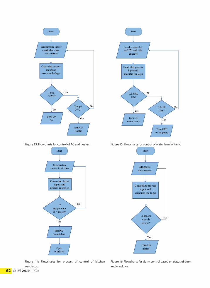
Step 5: initially the door sensor will be in closed position and whenever the closed contact breaks the alarm will be turned ON.
Step 6: when any unwanted gases is detected by the gas sensor, alarm will be turned ON, windows will be opened and ventilator will be turned ON.
Step 7: capacitor proximity sensor is used as smart switch. Whenever the sensor is disturbed the state of switch changes, that is ON/OFF can be done with any physical contact.
Step 8: if the PIR sensor detects any motion in its range the light in that particular area will be turned ON.
Figure 11-20 show completed logic functions presented as
flowchart diagrams. This is a universal language for
presenting of logical function of future systems. Flowcharts
is composed from unified symbols defined in standards and
it provides complex information about the functionality
of proposed system. Next procedure is to rewrite them
into desired program language specified for used control
system. For simple describing and writing of the program
all sequential procedures are divided into more simple
flowcharts, which will be executed in one or more control
systems. Flowcharts are also important for diagnostic and
mistake finding.
These flowcharts (fig. 21, 22, 23) have been rewritten to networks of ladder program and source code for Arduino microcontroller.
Also, Arduino code has been designed for processing the measured value of temperature, moisture and controlling of heater, fan and AC switching.
Figure 11: Flowcharts for process of irrigation.
Figure 12: Flowcharts for leakage of tank.
62 VOLUME 24, No. 1, 2020
Figure 13: Flowcharts for control of AC and heater.
Figure 14: Flowcharts for process of control of kitchen ventilator.
Figure 15: Flowcharts for control of water level of tank.
Figure 16: Flowcharts for alarm control based on status of door and windows.

Acta Mechanica SlovacaJournal published by Faculty of Mechanical Engineering - Technical University of Košice
63
Figure 17: Flowcharts for process of control of smoke detection.
Figure 18: Flowcharts for gas detection.
Figure 19: Flowcharts for smart switching process.
Figure 20: Flowcharts for motion detection.

64 VOLUME 24, No. 1, 2020
Figure 21: Network 1 and 2 from ladder program for PLC.
Figure 22: Network 3, 4, 5, 6 and 7 from ladder program for PLC.

Acta Mechanica SlovacaJournal published by Faculty of Mechanical Engineering - Technical University of Košice
65
Figure 23: Network 8, 9, 10, 11 and 12 from ladder program for PLC.
Figure 24: HMI environment design – Main
Screen.Figure 25: HMI environment Screen 1: controlling and maintaining water tank.
Figure 26: HMI environment Screen 2: controlling and maintaining waste water tank.

66 VOLUME 24, No. 1, 2020
8. Design of Human-machine interface Human Machine Interface (HMI) is a user
interface that makes bridge between human and PLC. With the help of HMI we can control and monitor the inputs and outputs. We can control the process and monitor the processes and we can access during run time. HMI is password protected. We can enter HMI only entering the password. On home screen (fig. 24) we can open the main door.
Once we entered through password we can access and monitor the systems that are controlled by PLC controller (fig. 25, 26).
If the door opened it will be indicated by the indicator.
There is NEXT and BACK to switch over screens.
9. Safety functions BACKUP POWER SUPPLYAs our system does not work without power
supply and during electricity shutdown we have installed invertor. This will provide electricity to the controller and for home. The reason we are using invertor is to protect and to maintain home security.
The invertor will be charged when the electricity is available and uses the stored energy in absence of electricity. This will take the home automation to next level.
PROTECTION FOR CONTROLLERIt is possible to get fire accidents or any other
unexpected incidents that may cause damage to the controller and due to that malfunction may occurs. To overcome this, we need to give protection for the controller. We need place it in a case or place which can keep the controller and its components protects from damage.
ROUTINE PASSWORD CHANGEWe need to change the password on HMI
frequently so that it will be more secure. Using the same password for more time periods may be unsafe. It may be known to strangers and they may misuse.
10. Final architecture of system System is composed of two control platforms
PLC and Arduino controller. Information are captured from low-cost sensors, which are primary designed for TTL logic platforms as Arduino. Several hardware circuits have been used for connection of these sensors to PLC controller. Other possible similar applications are in works [5-23]. The final
Figure 27: Final architecture of home automation system.
architecture is shown on figure 27.
11. Conclusions In this project it was necessary to make
automation of the entire home that makes more comfort and reduce the wastage of water and electricity and also provides more security. The intelligent house aims to simplify the operation of the household, both in terms of time, money, and in terms of comfort. The core of the entire smart home system is the control unit. It communicates with all connected appliances, from which it obtains the necessary information, for example about the temperature. It constantly evaluates this data and regulates the given sources and appliances based on the requirements. In the future, the pressure to use energy more efficiently in households will increase, so there is room for the application of automation in saving media and energy to achieve this requirement. For house with these properties it is very frequently called as energy-passive house. An energy-passive house or a passive house is a house that is more energy efficient than a low-energy house. In winter and summer, it provides a high quality indoor environment and at the same time allows you to significantly reduce energy

Acta Mechanica SlovacaJournal published by Faculty of Mechanical Engineering - Technical University of Košice
67
consumption for heating and operation in general. With a small increase in investment costs, it reduces the cost of running the house many times, saves non-renewable resources and reduces CO2 emissions, also increases living comfort, provides summer thermal comfort without air conditioning and does not need a conventional heating system - uses solar and internal heat gains, we can rest bring by ventilation. However, a smart home must not lack other handy solutions, such as securing homes, providing them with sensors and detectors or a smart irrigation system.
Even more important is the issue of household safety and security against criminal activities. Automation can also play an important role in these tasks. Protecting property against theft or classical household security, as most of us imagine, is an integral part of the vast majority of smarthome solutions. The security system can be formed by basic intelligent elements or a complex interconnection of various sensors and devices that work perfectly together.
As it was known reference from other previous projects, and it was upgraded some techniques which aren’t present in those projects. In future it is possible to do more updates and can used latest technological ideas which will make even smarter like biometric scans, facial recognitions, etc.
References and Notes[1] Puri, M. P., Advancement in Home Appliance Automation
Using PLC. 2016, June. Available online and Retrieved from
IRJET: https://www.irjet.net/archives/V3/i6/IRJETV3I6175.
pdf.
[2] Asadullah, M., & Khalil Ullah., Smart home automation
system using Bluetooth technology. April 2017. Available
online and retrieved from ieeexplore: https://ieeexplore.
ieee.org/document/7916544.
[3] Architecture of PLC. Programmable Logic Controllers – PLC.
August 2020. Available online and retrieved from https://
instrumentationforum.com/t/architecture-of-plc/7059.
[4] David, N., A. C., & A. U., Design of a Home Automation
System Using. June 2015, Available online and retrieved
from IJSER: https://www.ijser.org/researchpaper/Design-of-
aHome-Automation-System-Using-Arduino.pdf.
[5] Deshpande, V. S. Home automation using PLC. April
2015. Available online and retrieved from Slideshare:
https://www.slideshare.net/hemangpatel9041/home-
automation47431340.
[6] Kelemen, M., Virgala, I., Miková, Ľ, Frankovský, P., Experimental
Identification of Linear Actuator Properties. Acta Mechanica
Slovaca 2015, 19(1):42-47 | DOI: 10.21496/ams.2015.005.
[7] Marcinko, P., Virgala, I., Miková, Ľ, Prada, E., Kelemenová, T.,
Kelemen, M., Varga, M., Chimney Cleaning and Inspection
Robot. Acta Mechanica Slovaca 2019, 23(3):6-9 | DOI:
10.21496/ams.2019.016.
[8] Grossman, M., Conceive of mechatronic systems. Acta
Mechanica Slovaca 2018, 22(3):28-32 | DOI: 10.21496/
ams.2018.023.
[9] Višňovský, M., Rákay, R., Galajdová, A., Šimšík, D., Creating
Industrial Network with PROFINET Communication
for Education Purposes. Acta Mechanica Slovaca 2017,
21(4):66-72 | DOI: 10.21496/ams.2017.039
[10] Kelemenová, T., Kelemen, M., Miková, Ľ., Maxim, V., Prada,
E., Lipták, T., Menda, F., Model based design and HIL
simulations. American Journal of Mechanical Engineering.
Vol. 1, no. 7 (2013), p. 276-281. DOI:10.12691/ajme-1 -7 -2.
[11] Živčák, J., Kelemenová, T., Kelemen, M., Maxim, V., Model-
based Approach to Development of Engineering Systems.
Acta Mechanica Slovaca 2013, 17(3):56-62 | DOI: 10.21496/
ams.2013.033.
[12] Miková, Ľ., Kelemen, M., Gmiterko, A., Kačmár, L., Logical
circuits and their applications. Journal of Automation
and Control. Vol. 3, no. 3 (2015), p. 106-109. DOI:10.12691/
automation-3-3 -1.
[13] Heath, S., Embedded Systems Design. Elsevier. 2003. 2nd
edition. 430 pages. ISBN 0750655461.
[14] Li, Q., Yao, C., Real-Time Concepts for Embedded Systems.
CRC Press, 2003. 366 pages. ISBN 9781578201242.
[15] Virgala, I., Miková, Ľ., Kelemen, M., Lipták, T., Hroncová,
D., Microcontroller for mechatronic systems. Acta
Mechatronica. Vol. 2, No. 3 (2017), pp. 7-12.
[16] Miková, Ľ., Virgala, I., Kelemen, M., Embedded systems. Acta
Mechatronica. 2016. Vol. 3, No. 2 (2018), pp. 1-5.
[17] Kelemen, M., Prada, E., Kelemenová, T., Miková, Ľ., Virgala,
I., Lipták, T., Embedded systems via using microcontroller.
Applied Mechanics and Materials volume 816: Applied
Mechanics and Mechatronics 2. Zurich: TTP. 2015. pp. 248-
254.
[18] Zurawski, R., Embedded Systems Handbook. CRC Press,
2005. 1160 pages. ISBN 978142003816.
[19] Kamal, R., Embedded Systems: Architecture, Programming
and Design. McGraw-Hill Education, 2011. 681 pages. ISBN
9780070667648.
[20] Hwang, D., Schaumont, P., Tiri, K., Verbauwhede, I., Securing
Embedded Systems. IEEE Security & Privacy. IEEE Computer
Society. March/April 2006. pp. 40-49.
[21] Semjon, J., Vagaš, M., Baláž, V., The process projecting
automated and robotized system based on CA methods

68 VOLUME 24, No. 1, 2020
and modularity. In: International Scientific Herald. Vol. 3, no.
2 (2012), p. 156-160. - ISSN 2218-5348.
[22] Sukop, M., Hajduk, M., Baláž, V., Semjon, J., Vagaš, M.,
Increasing degree of automation of production systems
based on intelligent manipulation. Acta Mechanica Slovaca.
Roč. 15, č. 4 (2011), pp. 58-63. ISSN 1335-2393.
[23] Zander, J., Schieferdecker, I., Mosterman, P. J., Model-Based
Testing for Embedded Systems. CRC Press. 2017. 688 pages.
ISBN 978143981847.