Embed Size (px)
Citation preview
miniDSP Ltd, Hong Kong / www.minidsp.com / Features and specifications subject to change without prior notice 1
Home Theater Series
NANOAVR HD NANOAVR HDA
HIGH-RESOLUTION HDMI AUDIO PROCESSOR
User Manual
miniDSP Ltd, Hong Kong / www.minidsp.com / Features and specifications subject to change without prior notice 2
Revision history
Revision Description Date
1.0 Initial version 26 Jan 2014
1.1 Corrected package contents and time delay; links to app notes
11 Feb 2014
1.2 Additional items added to Troubleshooting
12 Mar 2014
1.3 Ethernet connectivity. 30 June 2014
1.4 Bass management information added, support portal link added.
28 Jul 2014
1.5 Update for Home Theater series 28 August 2014
1.6 Added nanoAVR HDA, HDMI channel mode, smartphone app
17 March 2015
miniDSP Ltd, Hong Kong / www.minidsp.com / Features and specifications subject to change without prior notice 3
CONTENTS
Important Information ......................................................................................................................................... 5
System Requirements ...................................................................................................................................... 5
Disclaimer/Warning ......................................................................................................................................... 6
Warranty Terms ............................................................................................................................................... 6
FCC Class B Statement...................................................................................................................................... 6
CE Mark Statement .......................................................................................................................................... 7
What's included ............................................................................................................................................... 7
A Note on this Manual ..................................................................................................................................... 7
1 Product Overview .......................................................................................................................................... 9
1.1 Typical usage – nanoAVR HD ................................................................................................................ 9
1.2 Typical usage – nanoAVR HDA ............................................................................................................ 10
2 Installation and setup .................................................................................................................................. 11
2.1 Hardware connectivity ....................................................................................................................... 11
2.1.1 HDMI input and output ............................................................................................................... 11
2.1.2 Analog outputs (nanoAVR HDA only) .......................................................................................... 12
2.1.3 DC Power .................................................................................................................................... 13
2.1.4 USB ............................................................................................................................................. 13
2.1.5 Ethernet ..................................................................................................................................... 14
2.2 Software installation .......................................................................................................................... 15
2.2.1 Windows .................................................................................................................................... 15
2.2.2 Mac OS X .................................................................................................................................... 16
3 Configuring the nanoAVR ............................................................................................................................ 17
3.1 Connecting to the nanoAVR ................................................................................................................ 18
3.1.1 USB ............................................................................................................................................. 18
3.1.2 Ethernet ..................................................................................................................................... 18
3.1.3 Options ....................................................................................................................................... 18
3.2 Global settings.................................................................................................................................... 19
3.3 Configure signal routing ..................................................................................................................... 20
3.4 Output channel setup ......................................................................................................................... 21
3.4.1 Channel label .............................................................................................................................. 21
3.4.2 Gain control and level monitoring ............................................................................................... 21
3.4.3 Parametric EQ............................................................................................................................. 22
3.4.4 Crossover settings....................................................................................................................... 24
3.4.5 Compressor ................................................................................................................................ 26
3.4.6 Time delay .................................................................................................................................. 26
3.4.7 Invert and mute .......................................................................................................................... 27
3.5 Bass management .............................................................................................................................. 27
3.6 Channel mode .................................................................................................................................... 29
3.7 Working with configurations .............................................................................................................. 30
3.7.1 Selecting a configuration ............................................................................................................ 30
3.7.2 Saving and loading configurations ............................................................................................... 31
miniDSP Ltd, Hong Kong / www.minidsp.com / Features and specifications subject to change without prior notice 4
3.7.3 Restoring to defaults................................................................................................................... 32
3.8 Keyboard Shortcuts ............................................................................................................................ 32
4 Using the nanoAVR ...................................................................................................................................... 33
4.1 Status indicators ................................................................................................................................. 33
4.2 Front panel controls ........................................................................................................................... 33
4.3 Infrared remote control ...................................................................................................................... 34
4.4 Smartphone control app ..................................................................................................................... 35
5 Acoustic measurement ................................................................................................................................ 36
5.1 What is acoustic measurement? ......................................................................................................... 36
5.2 Performing acoustic measurements ................................................................................................... 37
5.3 Adjusting equalizer settings ................................................................................................................ 38
5.3.1 Manual method .......................................................................................................................... 38
5.3.2 Automated method .................................................................................................................... 39
6 Additional information ................................................................................................................................ 40
6.1 Specifications ..................................................................................................................................... 40
6.2 Troubleshooting ................................................................................................................................. 41
6.3 MCU Firmware upgrade ..................................................................................................................... 42
6.4 Obtaining Support .............................................................................................................................. 42
miniDSP Ltd, Hong Kong / www.minidsp.com / Features and specifications subject to change without prior notice 5
IMPORTANT INFORMATION
Please read the following information before use. In case of any questions, please contact miniDSP via the
support portal at minidsp.desk.com.
SYSTEM REQUIREMENTS
To configure the nanoAVR, you will require a Windows PC or Apple Mac OS X computer with the following
minimum specification:
Windows
PC with 1GHz or higher processor clock speed. Intel® Pentium®/Celeron® family, or AMD K6®/AMD
Athlon®/AMD Duron® family, or compatible processor recommended.
512 megabytes (MB) of RAM or higher
Keyboard and mouse or compatible pointing device
Microsoft• ® Windows® Vista® SP1/ XP pro SP2/Win7/Win8.1
Microsoft• ® .NET framework v3.5 or later
Adobe AIR environment (latest version)
Adobe Flash player (latest version)
Mac OS X
Intel-based Mac with 1 GHz or higher processor clock speed
512 megabytes (MB) of RAM or higher
Keyboard and mouse or compatible pointing device
Mac OS X 10.4 or higher
Adobe AIR environment (latest version)
Adobe Flash player (latest version)
Both Platforms
For USB connectivity:
USB 2.0 port
For Ethernet connectivity via LAN:
Ethernet router with spare 100 Mbps port
For direct (ZeroConf) Ethernet connectivity:
Ethernet port on computer with 100 Mbps capability. (Apple Macs: a Thunderbolt port with a Thunderbolt to
Ethernet adapter.)
miniDSP Ltd, Hong Kong / www.minidsp.com / Features and specifications subject to change without prior notice 6
DISCLAIMER/WARNING
miniDSP cannot be held responsible for any damage that may result from the improper use of this product or
incorrect configuration of its settings. As with any other product, we recommend that you carefully read this
manual and other technical notes to ensure that you fully understand how to operate this product. The
nanoAVR is a powerful tool, and misuse or misconfiguration, such as incorrectly set gains or excessive boost, can
produce signals that may damage your audio system.
As a general guideline, you should perform the initial configuration of your nanoAVR before enabling audio
through any connected output device or amplification. Doing so will help ensure that the software is correctly
configured.
Finally, note that the nanoAVR is a very flexible device, and many of the questions we receive at the tech
support department are already answered in this user manual and in the online application notes on the
miniDSP.com website. So please take the time to carefully read this user manual and the online technical
support. Thanks for your understanding!
WARRANTY TERMS
miniDSP Ltd warrants this product to be free from defects in materials and workmanship for a period of one
year from the invoice date. Our warranty does not cover failure of the product due to incorrect connection or
installation, improper or undocumented use, unauthorized servicing, modification or alteration of the unit in any
way, or any usage outside of that recommended in this manual. If in doubt, contact miniDSP prior to use.
FCC CLASS B STATEMENT
This device complies with Part 15 of the FCC Rules. Operation is subject to the following two conditions:
This device may not cause harmful interference.
This device must accept any interference received, including interference that may cause undesired
operation.
Warning: This equipment has been tested and found to comply with the limits for a Class B digital device,
pursuant to Part 15 of the FCC Rules. These limits are designed to provide reasonable protection. This
equipment generates, uses and can radiate radio frequency energy and, if not installed and used in accordance
with the instructions, may cause interference to radio communications. However, there is no guarantee that
interference will not occur in a particular installation. If this equipment does cause harmful interference to radio
or television reception, which can be determined by turning the equipment off and on, the user is encouraged to
try to correct the interference by one or more of the following measures:
Reorient or relocate the receiving antenna.
Increase the separation between the equipment and receiver.
Connect the equipment into an outlet on a circuit different from that to which the receiver is connected.
Consult the dealer or an experienced radio/TV technician for help.
Notice: Shielded interface cable must be used in order to comply with emission limits.
miniDSP Ltd, Hong Kong / www.minidsp.com / Features and specifications subject to change without prior notice 7
Notice: Changes or modification not expressly approved by the party responsible for compliance could void the
user’s authority to operate the equipment.
CE MARK STATEMENT
The nanoAVR HD/HDA has passed the test performed according to European Standard EN 55022 Class B.
WHAT'S INCLUDED
Your nanoAVR package contains:
One nanoAVR HD or nanoAVR HDA HDMI audio processor
Universal 5 VDC power supply with interchangeable power pins
One USB cable for computer connectivity
One Ethernet cable
One HDMI cable
Printed Quick-start Guide
A NOTE ON THIS MANUAL
This User Manual is designed for reading in both print and on the computer. If printing the manual, please print
double-sided. The embedded page size is 8 ½” x 11”. Printing on A4 paper will result in a slightly reduced size.
For reading on the computer, we have included hyperlinked cross-references throughout the manual. In
addition, a table of contents is embedded in the PDF file, which will make navigation much easier:
In Adobe Reader on Windows, click on the “bookmarks” icon at the left. The table of contents will appear on
the left and can be unfolded at each level by clicking on the “+” icons.
In Preview on the Mac, click on the View menu and select Table of Contents. The table of contents will
appear on the left and can be unfolded at each level by clicking on the triangle icons.

miniDSP Ltd, Hong Kong / www.minidsp.com / Features and specifications subject to change without prior notice 8
miniDSP Ltd, Hong Kong / www.minidsp.com / Features and specifications subject to change without prior notice 9
1 PRODUCT OVERVIEW
The nanoAVR HD and nanoAVR HDA HDMI audio processors provide a comprehensive and sophisticated set of
digital audio processing functions for eight channels of high-resolution (24-bit, 96 kHz) HDMI audio. The
functions include bass management, parametric equalization, level adjustment, mixing and routing, and time
delay. All internal processing takes place at 96 kHz, with sample rates up to 192 kHz accepted over HDMI.
Two HDMI inputs are provided and can be switched from the front panel or by an infrared remote (not
included). The accepted audio format is multichannel linear PCM (LPCM). Video from the selected HDMI input is
switched directly to the output, with no video processing applied to the signal.
A user-friendly computer-based interface is used to configure the audio processing parameters of the nanoAVR
in real time. Up to four complete configuration presets can be stored. Once configuration is complete, the
computer is no longer needed and the presets can be recalled from the front panel, by an infrared remote, or
with a smartphone app.
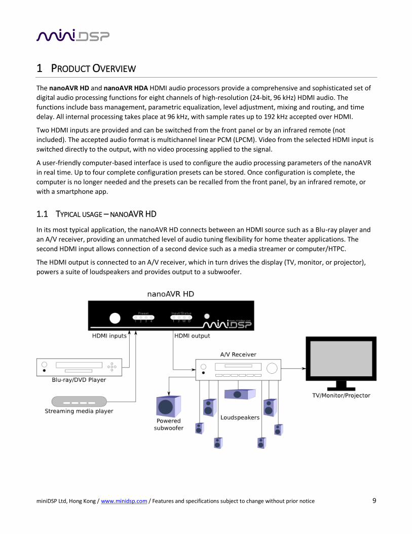
1.1 TYPICAL USAGE – NANOAVR HD
In its most typical application, the nanoAVR HD connects between an HDMI source such as a Blu-ray player and
an A/V receiver, providing an unmatched level of audio tuning flexibility for home theater applications. The
second HDMI input allows connection of a second device such as a media streamer or computer/HTPC.
The HDMI output is connected to an A/V receiver, which in turn drives the display (TV, monitor, or projector),
powers a suite of loudspeakers and provides output to a subwoofer.
miniDSP Ltd, Hong Kong / www.minidsp.com / Features and specifications subject to change without prior notice 10
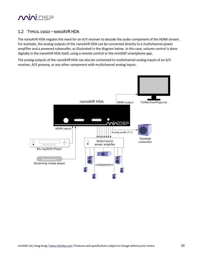
1.2 TYPICAL USAGE – NANOAVR HDA
The nanoAVR HDA negates the need for an A/V receiver to decode the audio component of the HDMI stream.
For example, the analog outputs of the nanoAVR HDA can be connected directly to a multichannel power
amplifier and a powered subwoofer, as illustrated in the diagram below. In this case, volume control is done
digitally in the nanoAVR HDA itself, using a remote control or the miniDSP smartphone app.
The analog outputs of the nanoAVR HDA can also be connected to multichannel analog inputs of an A/V
receiver, A/V preamp, or any other component with multichannel analog inputs.
miniDSP Ltd, Hong Kong / www.minidsp.com / Features and specifications subject to change without prior notice 11
2 INSTALLATION AND SETUP
2.1 HARDWARE CONNECTIVITY
All connections to the nanoAVR are made on the rear panel.
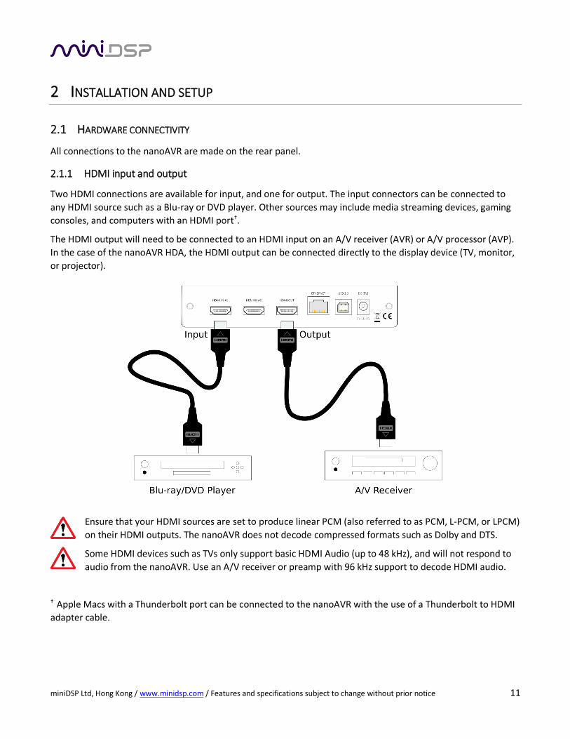
2.1.1 HDMI input and output
Two HDMI connections are available for input, and one for output. The input connectors can be connected to
any HDMI source such as a Blu-ray or DVD player. Other sources may include media streaming devices, gaming
consoles, and computers with an HDMI port†.
The HDMI output will need to be connected to an HDMI input on an A/V receiver (AVR) or A/V processor (AVP).
In the case of the nanoAVR HDA, the HDMI output can be connected directly to the display device (TV, monitor,
or projector).
Ensure that your HDMI sources are set to produce linear PCM (also referred to as PCM, L-PCM, or LPCM)
on their HDMI outputs. The nanoAVR does not decode compressed formats such as Dolby and DTS.
Some HDMI devices such as TVs only support basic HDMI Audio (up to 48 kHz), and will not respond to
audio from the nanoAVR. Use an A/V receiver or preamp with 96 kHz support to decode HDMI audio.
† Apple Macs with a Thunderbolt port can be connected to the nanoAVR with the use of a Thunderbolt to HDMI
adapter cable.
miniDSP Ltd, Hong Kong / www.minidsp.com / Features and specifications subject to change without prior notice 12
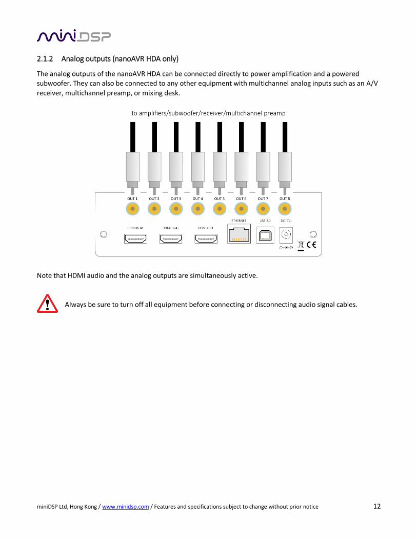
2.1.2 Analog outputs (nanoAVR HDA only)
The analog outputs of the nanoAVR HDA can be connected directly to power amplification and a powered
subwoofer. They can also be connected to any other equipment with multichannel analog inputs such as an A/V
receiver, multichannel preamp, or mixing desk.
Note that HDMI audio and the analog outputs are simultaneously active.
Always be sure to turn off all equipment before connecting or disconnecting audio signal cables.
miniDSP Ltd, Hong Kong / www.minidsp.com / Features and specifications subject to change without prior notice 13
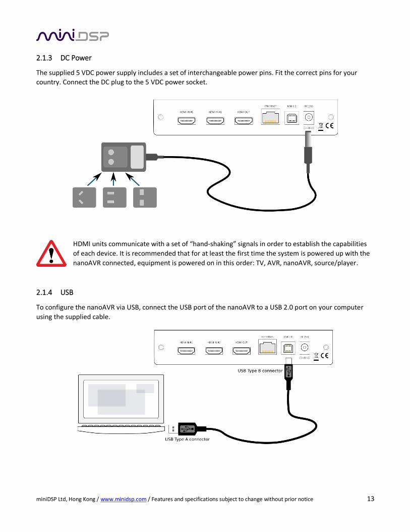
2.1.3 DC Power
The supplied 5 VDC power supply includes a set of interchangeable power pins. Fit the correct pins for your
country. Connect the DC plug to the 5 VDC power socket.
HDMI units communicate with a set of “hand-shaking” signals in order to establish the capabilities
of each device. It is recommended that for at least the first time the system is powered up with the
nanoAVR connected, equipment is powered on in this order: TV, AVR, nanoAVR, source/player.
2.1.4 USB
To configure the nanoAVR via USB, connect the USB port of the nanoAVR to a USB 2.0 port on your computer
using the supplied cable.
miniDSP Ltd, Hong Kong / www.minidsp.com / Features and specifications subject to change without prior notice 14
2.1.5 Ethernet
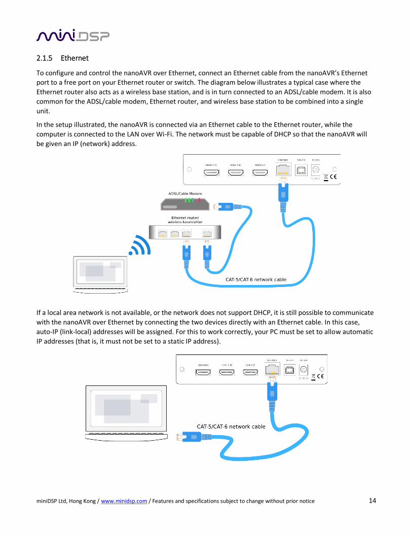
To configure and control the nanoAVR over Ethernet, connect an Ethernet cable from the nanoAVR’s Ethernet
port to a free port on your Ethernet router or switch. The diagram below illustrates a typical case where the
Ethernet router also acts as a wireless base station, and is in turn connected to an ADSL/cable modem. It is also
common for the ADSL/cable modem, Ethernet router, and wireless base station to be combined into a single
unit.
In the setup illustrated, the nanoAVR is connected via an Ethernet cable to the Ethernet router, while the
computer is connected to the LAN over Wi-Fi. The network must be capable of DHCP so that the nanoAVR will
be given an IP (network) address.
If a local area network is not available, or the network does not support DHCP, it is still possible to communicate
with the nanoAVR over Ethernet by connecting the two devices directly with an Ethernet cable. In this case,
auto-IP (link-local) addresses will be assigned. For this to work correctly, your PC must be set to allow automatic
IP addresses (that is, it must not be set to a static IP address).
miniDSP Ltd, Hong Kong / www.minidsp.com / Features and specifications subject to change without prior notice 15
2.2 SOFTWARE INSTALLATION
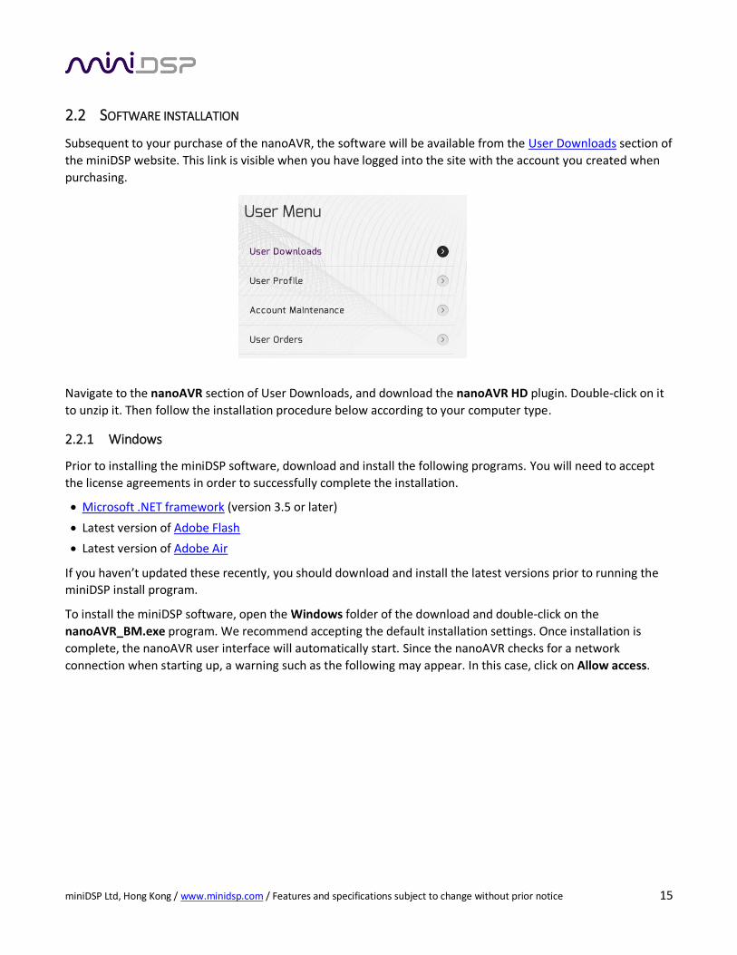
Subsequent to your purchase of the nanoAVR, the software will be available from the User Downloads section of
the miniDSP website. This link is visible when you have logged into the site with the account you created when
purchasing.
Navigate to the nanoAVR section of User Downloads, and download the nanoAVR HD plugin. Double-click on it
to unzip it. Then follow the installation procedure below according to your computer type.
2.2.1 Windows
Prior to installing the miniDSP software, download and install the following programs. You will need to accept
the license agreements in order to successfully complete the installation.
Microsoft .NET framework (version 3.5 or later)
Latest version of Adobe Flash
Latest version of Adobe Air
If you haven’t updated these recently, you should download and install the latest versions prior to running the
miniDSP install program.
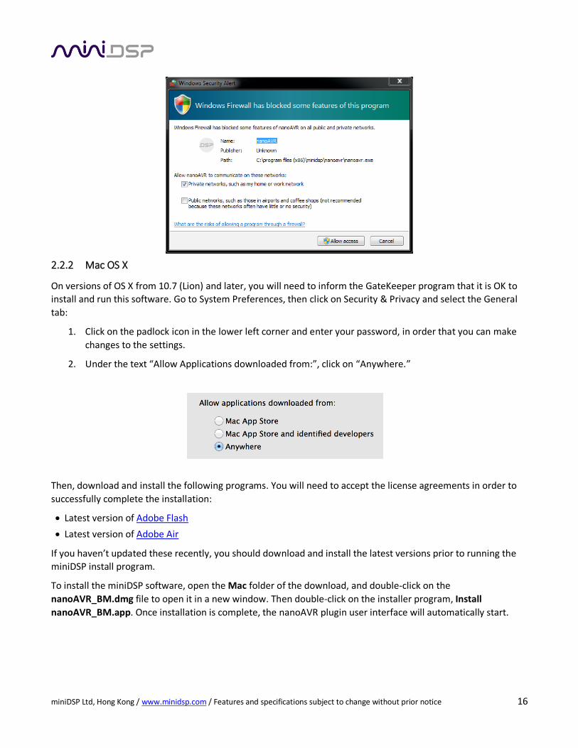
To install the miniDSP software, open the Windows folder of the download and double-click on the
nanoAVR_BM.exe program. We recommend accepting the default installation settings. Once installation is
complete, the nanoAVR user interface will automatically start. Since the nanoAVR checks for a network
connection when starting up, a warning such as the following may appear. In this case, click on Allow access.
miniDSP Ltd, Hong Kong / www.minidsp.com / Features and specifications subject to change without prior notice 16
2.2.2 Mac OS X
On versions of OS X from 10.7 (Lion) and later, you will need to inform the GateKeeper program that it is OK to
install and run this software. Go to System Preferences, then click on Security & Privacy and select the General
tab:
1. Click on the padlock icon in the lower left corner and enter your password, in order that you can make
changes to the settings.
2. Under the text “Allow Applications downloaded from:”, click on “Anywhere.”
Then, download and install the following programs. You will need to accept the license agreements in order to
successfully complete the installation:
Latest version of Adobe Flash
Latest version of Adobe Air
If you haven’t updated these recently, you should download and install the latest versions prior to running the
miniDSP install program.
To install the miniDSP software, open the Mac folder of the download, and double-click on the
nanoAVR_BM.dmg file to open it in a new window. Then double-click on the installer program, Install
nanoAVR_BM.app. Once installation is complete, the nanoAVR plugin user interface will automatically start.
miniDSP Ltd, Hong Kong / www.minidsp.com / Features and specifications subject to change without prior notice 17
3 CONFIGURING THE NANOAVR
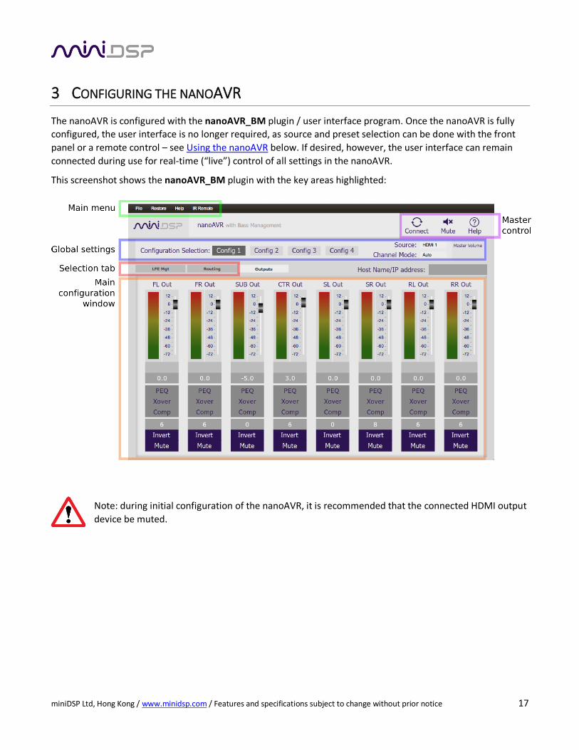
The nanoAVR is configured with the nanoAVR_BM plugin / user interface program. Once the nanoAVR is fully
configured, the user interface is no longer required, as source and preset selection can be done with the front
panel or a remote control – see Using the nanoAVR below. If desired, however, the user interface can remain
connected during use for real-time (“live”) control of all settings in the nanoAVR.
This screenshot shows the nanoAVR_BM plugin with the key areas highlighted:
Note: during initial configuration of the nanoAVR, it is recommended that the connected HDMI output
device be muted.
miniDSP Ltd, Hong Kong / www.minidsp.com / Features and specifications subject to change without prior notice 18
3.1 CONNECTING TO THE NANOAVR
Communication with the nanoAVR can take place either over USB or Ethernet.
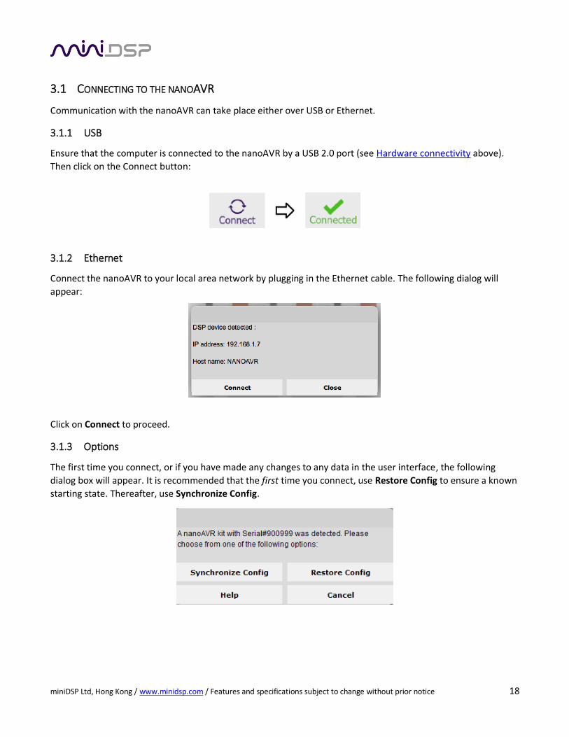
3.1.1 USB
Ensure that the computer is connected to the nanoAVR by a USB 2.0 port (see Hardware connectivity above).
Then click on the Connect button:
3.1.2 Ethernet
Connect the nanoAVR to your local area network by plugging in the Ethernet cable. The following dialog will
appear:
Click on Connect to proceed.
3.1.3 Options
The first time you connect, or if you have made any changes to any data in the user interface, the following
dialog box will appear. It is recommended that the first time you connect, use Restore Config to ensure a known
starting state. Thereafter, use Synchronize Config.
miniDSP Ltd, Hong Kong / www.minidsp.com / Features and specifications subject to change without prior notice 19
The options are:
Synchronize Config
Download the currently selected configuration into the corresponding configuration preset of
the nanoAVR. After downloading the configuration data, the user interface remains connected
to the nanoAVR and any changes to processing parameters will be downloaded immediately in
real time to the nanoAVR. That is, the nanoAVR is now “live.”
Synchronize and Upgrade
This is similar to Synchronize Config, but also upgrades the internal data of the nanoAVR. This
option may appear when connecting to the nanoAVR after an update to the plugin.
Restore Config
Restore the data in the currently selected configuration to the factory defaults. When using this
option, the HDMI output device should be muted until you have set the configuration to a
working state.
Help This option brings up a help screen explaining the options.
Cancel This option cancels the attempt to connect to the nanoAVR. The user interface will remain
disconnected.
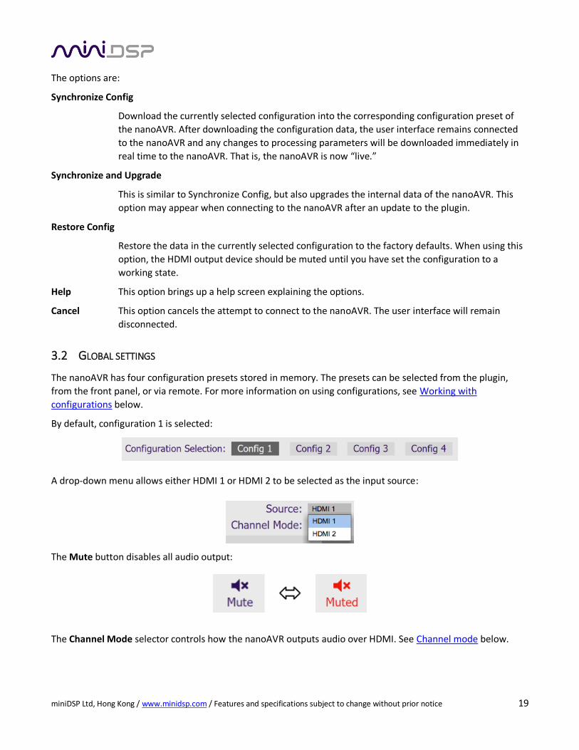
3.2 GLOBAL SETTINGS
The nanoAVR has four configuration presets stored in memory. The presets can be selected from the plugin,
from the front panel, or via remote. For more information on using configurations, see Working with
configurations below.
By default, configuration 1 is selected:
A drop-down menu allows either HDMI 1 or HDMI 2 to be selected as the input source:
The Mute button disables all audio output:
The Channel Mode selector controls how the nanoAVR outputs audio over HDMI. See Channel mode below.
miniDSP Ltd, Hong Kong / www.minidsp.com / Features and specifications subject to change without prior notice 20
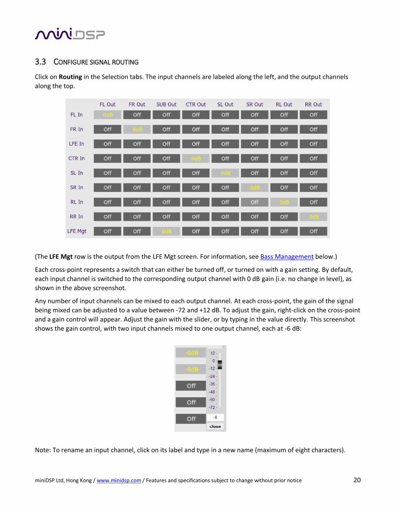
3.3 CONFIGURE SIGNAL ROUTING
Click on Routing in the Selection tabs. The input channels are labeled along the left, and the output channels
along the top.
(The LFE Mgt row is the output from the LFE Mgt screen. For information, see Bass Management below.)
Each cross-point represents a switch that can either be turned off, or turned on with a gain setting. By default,
each input channel is switched to the corresponding output channel with 0 dB gain (i.e. no change in level), as
shown in the above screenshot.
Any number of input channels can be mixed to each output channel. At each cross-point, the gain of the signal
being mixed can be adjusted to a value between -72 and +12 dB. To adjust the gain, right-click on the cross-point
and a gain control will appear. Adjust the gain with the slider, or by typing in the value directly. This screenshot
shows the gain control, with two input channels mixed to one output channel, each at -6 dB:
Note: To rename an input channel, click on its label and type in a new name (maximum of eight characters).
miniDSP Ltd, Hong Kong / www.minidsp.com / Features and specifications subject to change without prior notice 21
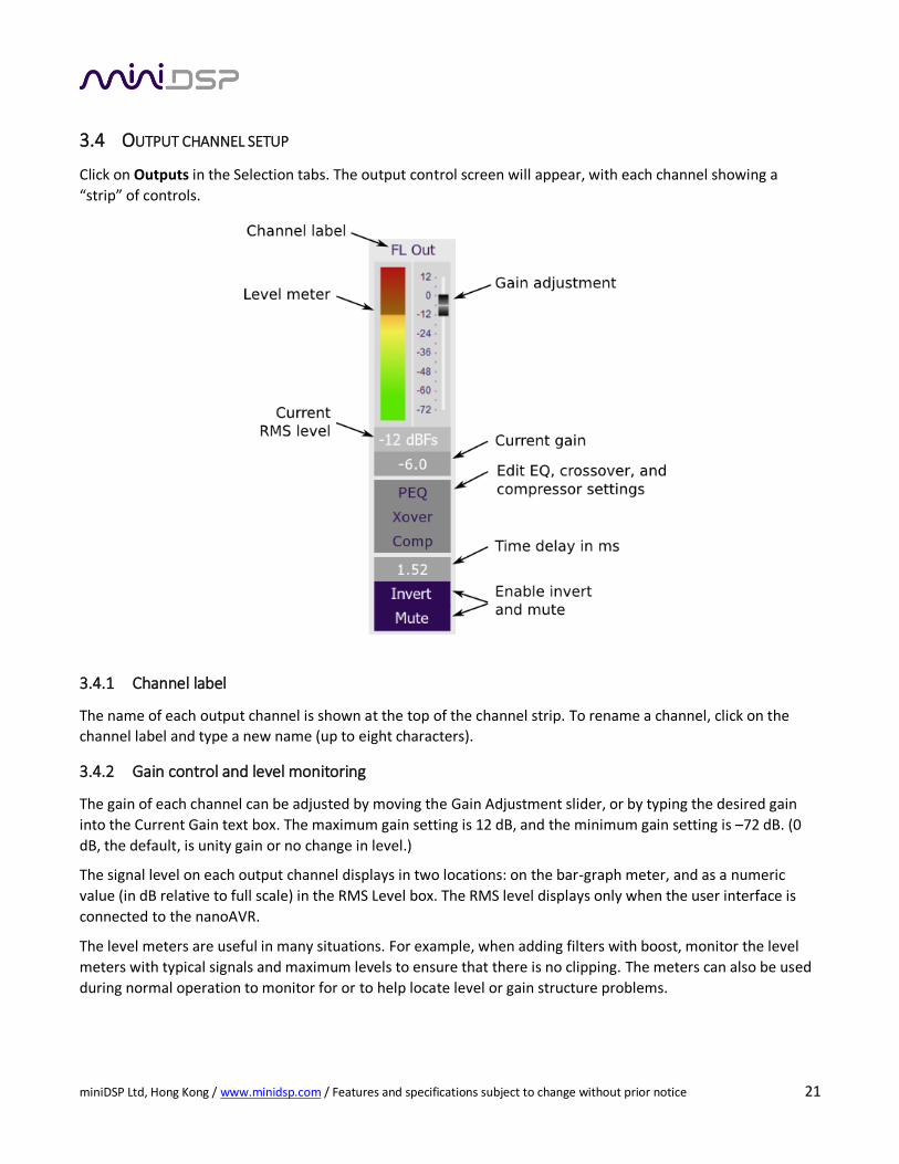
3.4 OUTPUT CHANNEL SETUP
Click on Outputs in the Selection tabs. The output control screen will appear, with each channel showing a
“strip” of controls.
3.4.1 Channel label
The name of each output channel is shown at the top of the channel strip. To rename a channel, click on the
channel label and type a new name (up to eight characters).
3.4.2 Gain control and level monitoring
The gain of each channel can be adjusted by moving the Gain Adjustment slider, or by typing the desired gain
into the Current Gain text box. The maximum gain setting is 12 dB, and the minimum gain setting is –72 dB. (0
dB, the default, is unity gain or no change in level.)
The signal level on each output channel displays in two locations: on the bar-graph meter, and as a numeric
value (in dB relative to full scale) in the RMS Level box. The RMS level displays only when the user interface is
connected to the nanoAVR.
The level meters are useful in many situations. For example, when adding filters with boost, monitor the level
meters with typical signals and maximum levels to ensure that there is no clipping. The meters can also be used
during normal operation to monitor for or to help locate level or gain structure problems.
miniDSP Ltd, Hong Kong / www.minidsp.com / Features and specifications subject to change without prior notice 22
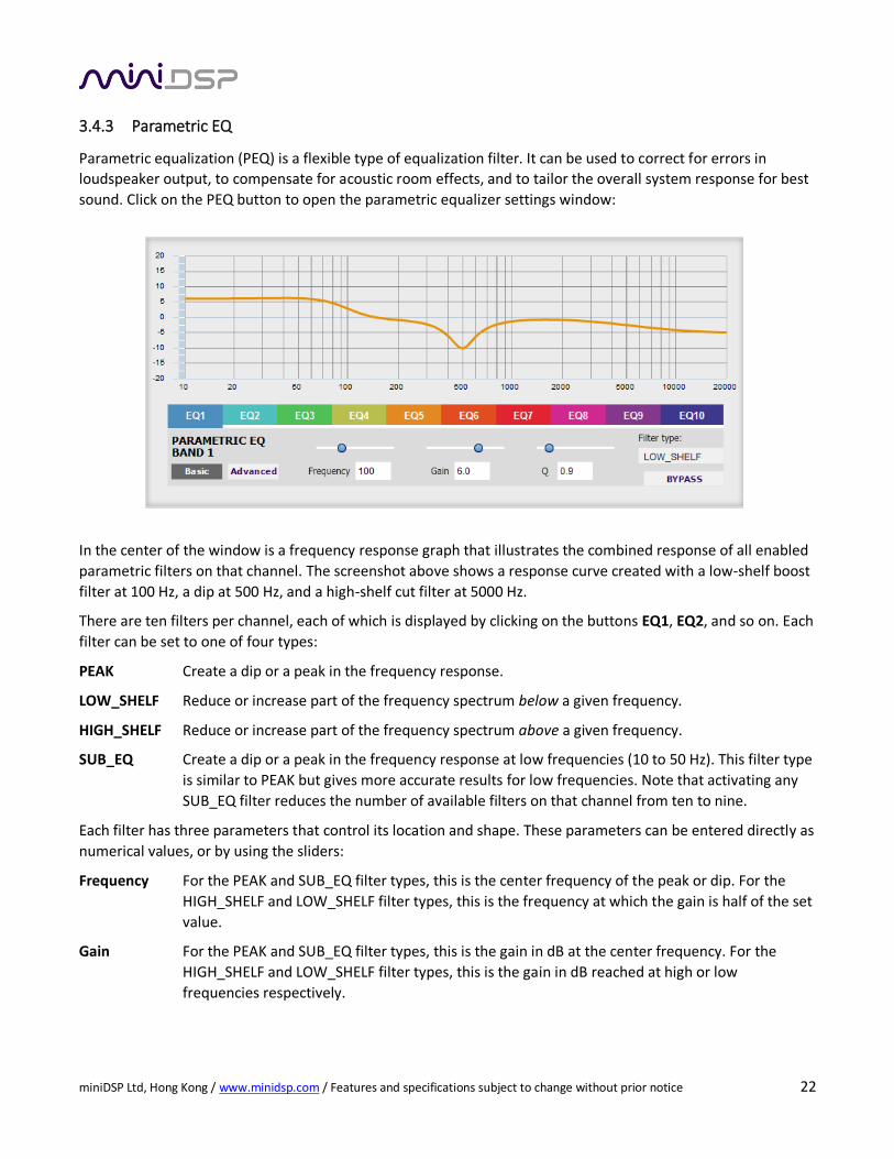
3.4.3 Parametric EQ
Parametric equalization (PEQ) is a flexible type of equalization filter. It can be used to correct for errors in
loudspeaker output, to compensate for acoustic room effects, and to tailor the overall system response for best
sound. Click on the PEQ button to open the parametric equalizer settings window:
In the center of the window is a frequency response graph that illustrates the combined response of all enabled
parametric filters on that channel. The screenshot above shows a response curve created with a low-shelf boost
filter at 100 Hz, a dip at 500 Hz, and a high-shelf cut filter at 5000 Hz.
There are ten filters per channel, each of which is displayed by clicking on the buttons EQ1, EQ2, and so on. Each
filter can be set to one of four types:
PEAK Create a dip or a peak in the frequency response.
LOW_SHELF Reduce or increase part of the frequency spectrum below a given frequency.
HIGH_SHELF Reduce or increase part of the frequency spectrum above a given frequency.
SUB_EQ Create a dip or a peak in the frequency response at low frequencies (10 to 50 Hz). This filter type
is similar to PEAK but gives more accurate results for low frequencies. Note that activating any
SUB_EQ filter reduces the number of available filters on that channel from ten to nine.
Each filter has three parameters that control its location and shape. These parameters can be entered directly as
numerical values, or by using the sliders:
Frequency For the PEAK and SUB_EQ filter types, this is the center frequency of the peak or dip. For the
HIGH_SHELF and LOW_SHELF filter types, this is the frequency at which the gain is half of the set
value.
Gain For the PEAK and SUB_EQ filter types, this is the gain in dB at the center frequency. For the
HIGH_SHELF and LOW_SHELF filter types, this is the gain in dB reached at high or low
frequencies respectively.
miniDSP Ltd, Hong Kong / www.minidsp.com / Features and specifications subject to change without prior notice 23
Q Q controls the “sharpness” of the filter. For the PEAK and SUB_EQ filter types, lower Q gives a
shallower peak or dip, while higher Q gives a narrower peak or dip. For the HIGH_SHELF and
LOW_SHELF filter types, Q controls how quickly the filter transitions from no gain to maximum
gain.
To disable or enable a filter, click on the Bypass button. A filter will also have no effect if its gain is set to 0.0.
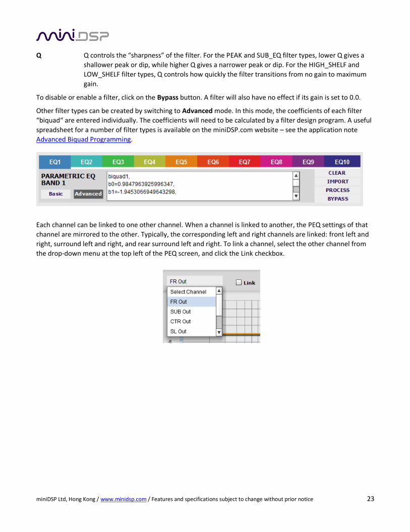
Other filter types can be created by switching to Advanced mode. In this mode, the coefficients of each filter
“biquad“ are entered individually. The coefficients will need to be calculated by a filter design program. A useful
spreadsheet for a number of filter types is available on the miniDSP.com website – see the application note
Advanced Biquad Programming.
Each channel can be linked to one other channel. When a channel is linked to another, the PEQ settings of that
channel are mirrored to the other. Typically, the corresponding left and right channels are linked: front left and
right, surround left and right, and rear surround left and right. To link a channel, select the other channel from
the drop-down menu at the top left of the PEQ screen, and click the Link checkbox.
miniDSP Ltd, Hong Kong / www.minidsp.com / Features and specifications subject to change without prior notice 24
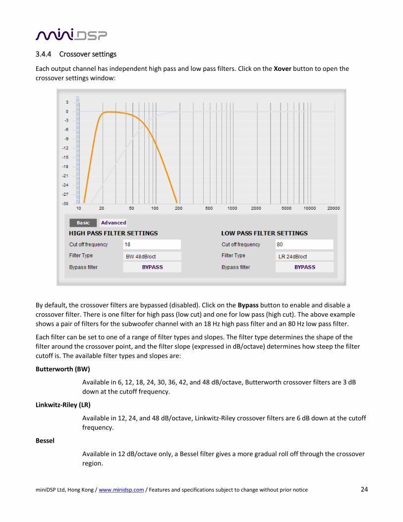
3.4.4 Crossover settings
Each output channel has independent high pass and low pass filters. Click on the Xover button to open the
crossover settings window:
By default, the crossover filters are bypassed (disabled). Click on the Bypass button to enable and disable a
crossover filter. There is one filter for high pass (low cut) and one for low pass (high cut). The above example
shows a pair of filters for the subwoofer channel with an 18 Hz high pass filter and an 80 Hz low pass filter.
Each filter can be set to one of a range of filter types and slopes. The filter type determines the shape of the
filter around the crossover point, and the filter slope (expressed in dB/octave) determines how steep the filter
cutoff is. The available filter types and slopes are:
Butterworth (BW)
Available in 6, 12, 18, 24, 30, 36, 42, and 48 dB/octave, Butterworth crossover filters are 3 dB
down at the cutoff frequency.
Linkwitz-Riley (LR)
Available in 12, 24, and 48 dB/octave, Linkwitz-Riley crossover filters are 6 dB down at the cutoff
frequency.
Bessel
Available in 12 dB/octave only, a Bessel filter gives a more gradual roll off through the crossover
region.
miniDSP Ltd, Hong Kong / www.minidsp.com / Features and specifications subject to change without prior notice 25
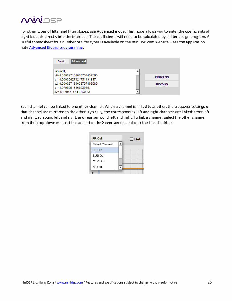
For other types of filter and filter slopes, use Advanced mode. This mode allows you to enter the coefficients of
eight biquads directly into the interface. The coefficients will need to be calculated by a filter design program. A
useful spreadsheet for a number of filter types is available on the miniDSP.com website – see the application
note Advanced Biquad programming.
Each channel can be linked to one other channel. When a channel is linked to another, the crossover settings of
that channel are mirrored to the other. Typically, the corresponding left and right channels are linked: front left
and right, surround left and right, and rear surround left and right. To link a channel, select the other channel
from the drop-down menu at the top left of the Xover screen, and click the Link checkbox.
miniDSP Ltd, Hong Kong / www.minidsp.com / Features and specifications subject to change without prior notice 26
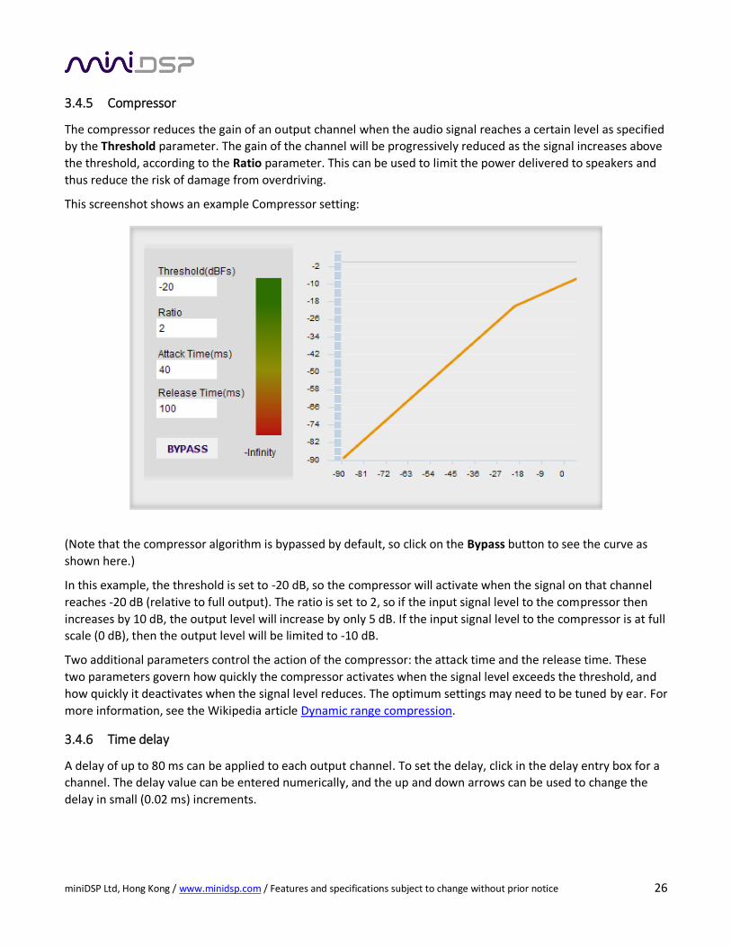
3.4.5 Compressor
The compressor reduces the gain of an output channel when the audio signal reaches a certain level as specified
by the Threshold parameter. The gain of the channel will be progressively reduced as the signal increases above
the threshold, according to the Ratio parameter. This can be used to limit the power delivered to speakers and
thus reduce the risk of damage from overdriving.
This screenshot shows an example Compressor setting:
(Note that the compressor algorithm is bypassed by default, so click on the Bypass button to see the curve as
shown here.)
In this example, the threshold is set to -20 dB, so the compressor will activate when the signal on that channel
reaches -20 dB (relative to full output). The ratio is set to 2, so if the input signal level to the compressor then
increases by 10 dB, the output level will increase by only 5 dB. If the input signal level to the compressor is at full
scale (0 dB), then the output level will be limited to -10 dB.
Two additional parameters control the action of the compressor: the attack time and the release time. These
two parameters govern how quickly the compressor activates when the signal level exceeds the threshold, and
how quickly it deactivates when the signal level reduces. The optimum settings may need to be tuned by ear. For
more information, see the Wikipedia article Dynamic range compression.
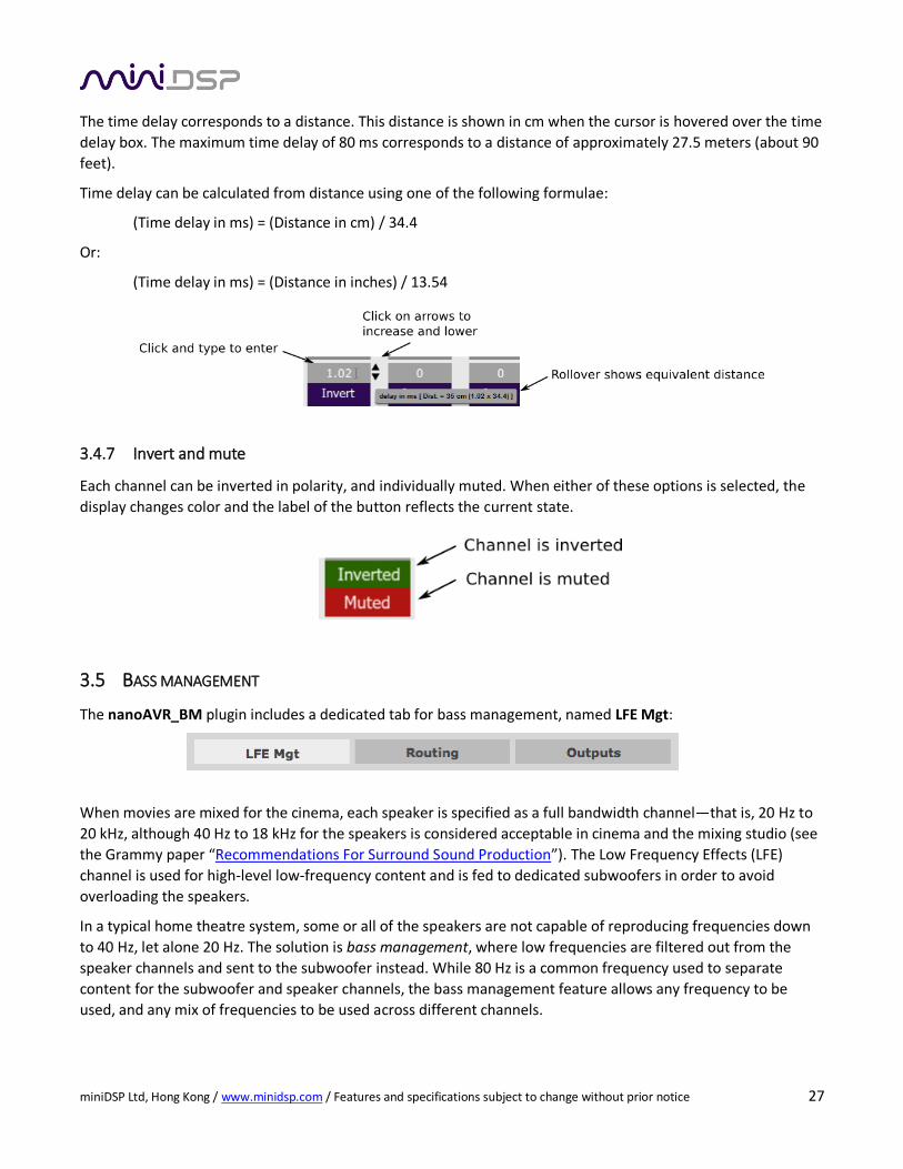
3.4.6 Time delay
A delay of up to 80 ms can be applied to each output channel. To set the delay, click in the delay entry box for a
channel. The delay value can be entered numerically, and the up and down arrows can be used to change the
delay in small (0.02 ms) increments.
miniDSP Ltd, Hong Kong / www.minidsp.com / Features and specifications subject to change without prior notice 27
The time delay corresponds to a distance. This distance is shown in cm when the cursor is hovered over the time
delay box. The maximum time delay of 80 ms corresponds to a distance of approximately 27.5 meters (about 90
feet).
Time delay can be calculated from distance using one of the following formulae:
(Time delay in ms) = (Distance in cm) / 34.4
Or:
(Time delay in ms) = (Distance in inches) / 13.54
3.4.7 Invert and mute
Each channel can be inverted in polarity, and individually muted. When either of these options is selected, the
display changes color and the label of the button reflects the current state.
3.5 BASS MANAGEMENT
The nanoAVR_BM plugin includes a dedicated tab for bass management, named LFE Mgt:
When movies are mixed for the cinema, each speaker is specified as a full bandwidth channel—that is, 20 Hz to
20 kHz, although 40 Hz to 18 kHz for the speakers is considered acceptable in cinema and the mixing studio (see
the Grammy paper “Recommendations For Surround Sound Production”). The Low Frequency Effects (LFE)
channel is used for high-level low-frequency content and is fed to dedicated subwoofers in order to avoid
overloading the speakers.
In a typical home theatre system, some or all of the speakers are not capable of reproducing frequencies down
to 40 Hz, let alone 20 Hz. The solution is bass management, where low frequencies are filtered out from the
speaker channels and sent to the subwoofer instead. While 80 Hz is a common frequency used to separate
content for the subwoofer and speaker channels, the bass management feature allows any frequency to be
used, and any mix of frequencies to be used across different channels.
miniDSP Ltd, Hong Kong / www.minidsp.com / Features and specifications subject to change without prior notice 28
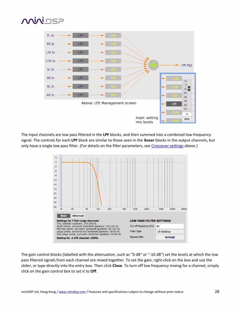
The input channels are low pass filtered in the LPF blocks, and then summed into a combined low-frequency
signal. The controls for each LPF block are similar to those seen in the Xover blocks in the output channels, but
only have a single low pass filter. (For details on the filter parameters, see Crossover settings above.)
The gain control blocks (labelled with the attenuation, such as "0 dB" or "-10 dB") set the levels at which the low
pass filtered signals from each channel are mixed together. To set the gain, right-click on the box and use the
slider, or type directly into the entry box. Then click Close. To turn off low frequency mixing for a channel, simply
click on the gain control box to set it to Off.
miniDSP Ltd, Hong Kong / www.minidsp.com / Features and specifications subject to change without prior notice 29
Note that the mix levels for the speaker channels are normally set 10 dB lower than the LFE channel—see the
application note Bass Management with the nanoAVR for full details.
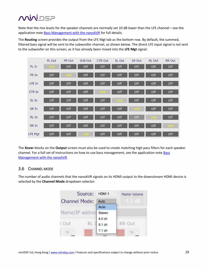
The Routing screen provides the output from the LFE Mgt tab as the bottom row. By default, the summed,
filtered bass signal will be sent to the subwoofer channel, as shown below. The direct LFE input signal is not sent
to the subwoofer on this screen, as it has already been mixed into the LFE Mgt signal:
The Xover blocks on the Output screen must also be used to create matching high pass filters for each speaker
channel. For a full set of instructions on how to use bass management, see the application note Bass
Management with the nanoAVR.
3.6 CHANNEL MODE
The number of audio channels that the nanoAVR signals on its HDMI output to the downstream HDMI device is
selected by the Channel Mode dropdown selector:

miniDSP Ltd, Hong Kong / www.minidsp.com / Features and specifications subject to change without prior notice 30
Auto The number of output channels signaled is the same as receives on the selected. For example, if
the selected source signals that HDMI audio is carrying a stereo signal, the nanoAVR passes this
to its output. If the source signals that HDMI audio is carrying six channels (5.1), the nanoAVR
passes this to its output. And so on.
Stereo The nanoAVR always signals stereo output, regardless of the number of input channels.
4.0 The nanoAVR always signals four-channel output, regardless of the number of input channels.
5.1 The nanoAVR always signals six-channel output, regardless of the number of input channels.
7.1 The nanoAVR always signals eight-channel output, regardless of the number of input channels.
The setting of Channel Mode has no effect on the analog output channels (nanoAVR HDA only).
3.7 WORKING WITH CONFIGURATIONS
The complete set of data that controls the audio processing of the nanoAVR is called a configuration. The
nanoAVR stores four configuration presets in its internal memory, which can then be selected from the plugin
user interface, the front panel or via remote control.
The effect of changes made in the user interface fall into two categories:
The user interface is connected to the nanoAVR
The user interface is “live” – that is, any changes made to the audio processing parameters in
the user interface are downloaded immediately to the nanoAVR. The effect of these changes will
thus be audible as the changes are made.
The user interface is not connected to the nanoAVR
Changes made to the audio processing parameters will be made locally in the user interface
only. The next time the user interface is connected to the nanoAVR, the audio processing
parameters will be downloaded to the nanoAVR (as long as the Synchronize Config button is
selected). Changes are not lost between quitting and restarting the user interface.
3.7.1 Selecting a configuration
The current configuration is selected by one of the four buttons in the Configuration Selection area. By default,
configuration 1 is selected:
To switch to a different configuration, click on a different button. If the interface is live, real-time processing in
the nanoAVR will be updated to the newly selected configuration, and audio processing will then continue. If,
however, the selected configuration has changed in the user interface since the newly selected configuration
was last synchronized to the nanoAVR, then a dialog will appear asking you if you want to synchronize the local
configuration to the nanoAVR.
miniDSP Ltd, Hong Kong / www.minidsp.com / Features and specifications subject to change without prior notice 31
If the user interface is not connected, then the screen will update to show the parameters of the newly selected
configuration. If this configuration is changed in the user interface, it will be downloaded to the nanoAVR next
time it is synchronized.
Note: because of the potential for a selected configuration to be in an unknown state, we
recommend that each configuration be selected and checked/initialized prior to connecting to the
nanoAVR for the first time.
3.7.2 Saving and loading configurations
Configurations can be saved to and loaded from files. Each configuration is stored in a separate file. It is strongly
recommended that each configuration programmed into the nanoAVR be saved to a file, to ensure that the
configuration is not lost if the nanoAVR is inadvertently reset. A configuration file stores all of the audio
processing parameters except for the master volume setting and the HDMI input selection.
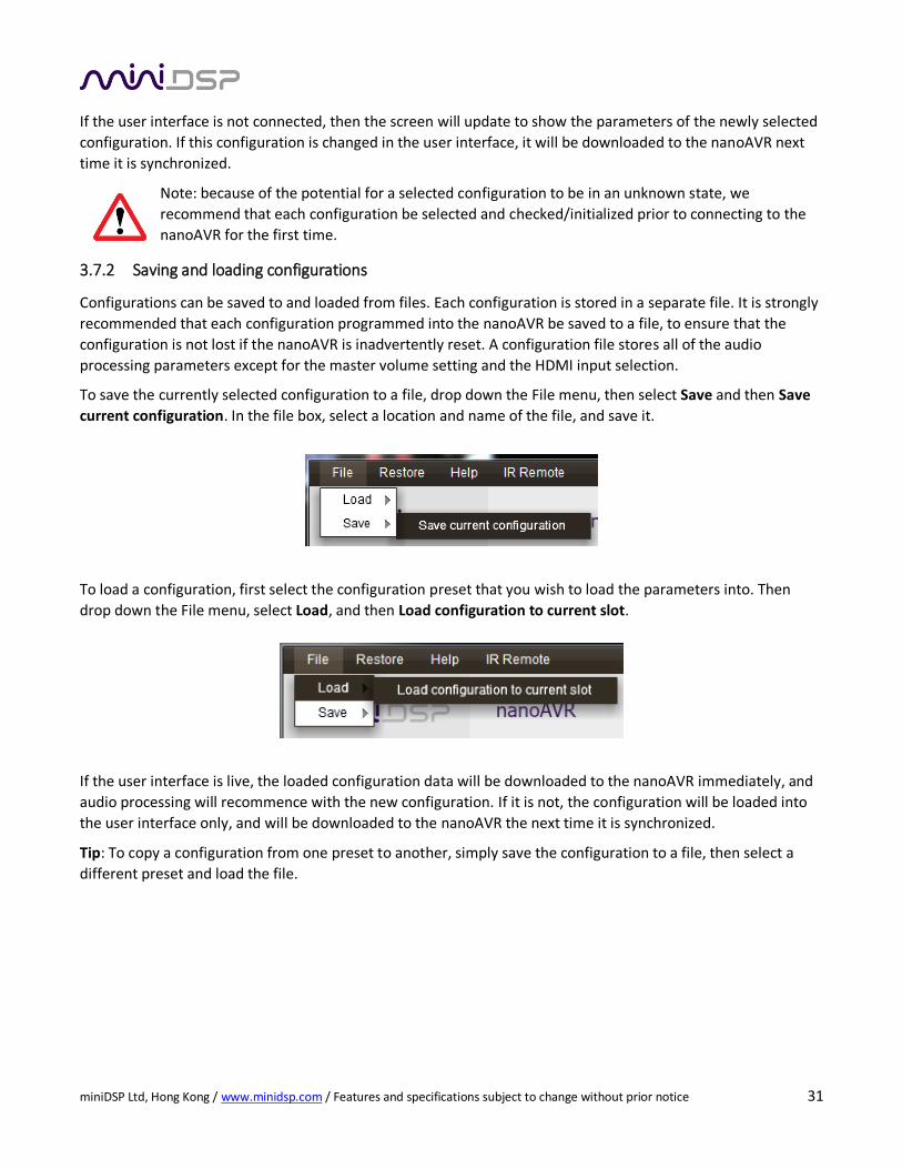
To save the currently selected configuration to a file, drop down the File menu, then select Save and then Save
current configuration. In the file box, select a location and name of the file, and save it.
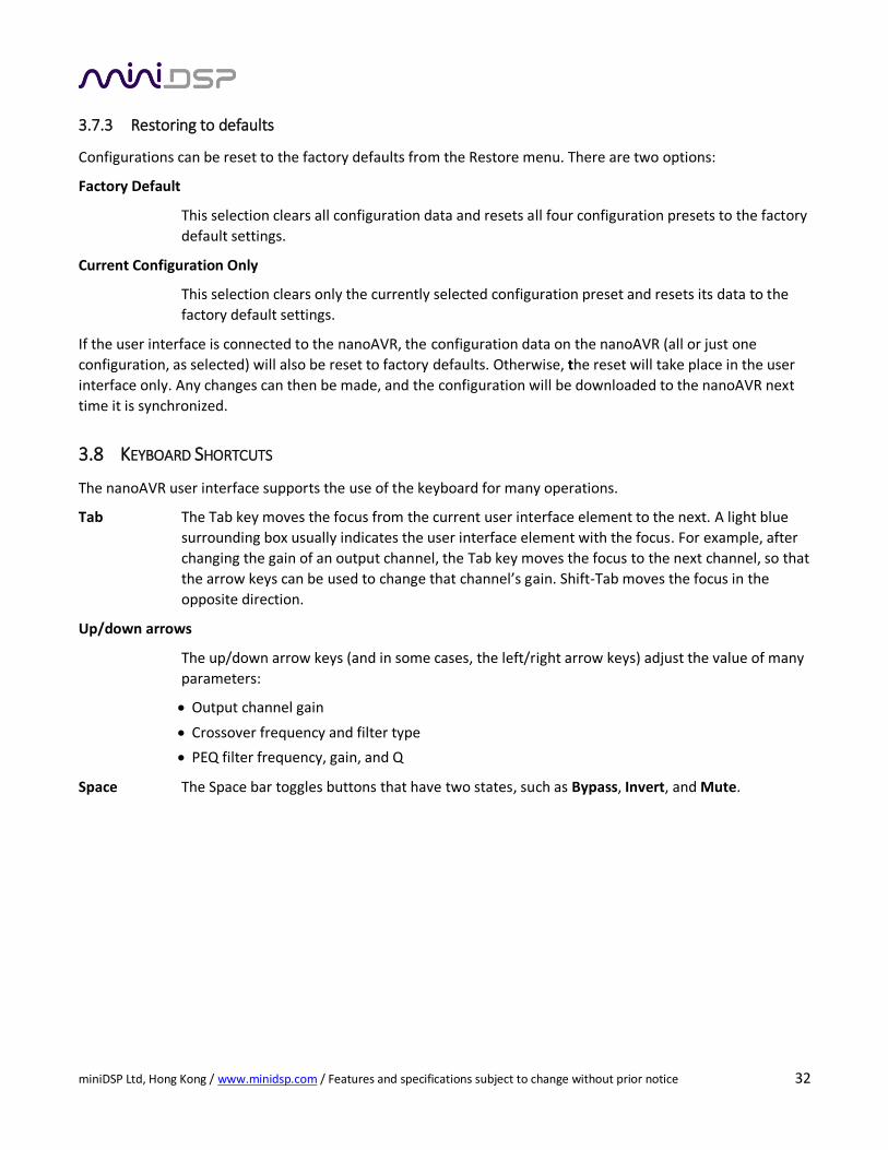
To load a configuration, first select the configuration preset that you wish to load the parameters into. Then
drop down the File menu, select Load, and then Load configuration to current slot.
If the user interface is live, the loaded configuration data will be downloaded to the nanoAVR immediately, and
audio processing will recommence with the new configuration. If it is not, the configuration will be loaded into
the user interface only, and will be downloaded to the nanoAVR the next time it is synchronized.
Tip: To copy a configuration from one preset to another, simply save the configuration to a file, then select a
different preset and load the file.
miniDSP Ltd, Hong Kong / www.minidsp.com / Features and specifications subject to change without prior notice 32
3.7.3 Restoring to defaults
Configurations can be reset to the factory defaults from the Restore menu. There are two options:
Factory Default
This selection clears all configuration data and resets all four configuration presets to the factory
default settings.
Current Configuration Only
This selection clears only the currently selected configuration preset and resets its data to the
factory default settings.
If the user interface is connected to the nanoAVR, the configuration data on the nanoAVR (all or just one
configuration, as selected) will also be reset to factory defaults. Otherwise, the reset will take place in the user
interface only. Any changes can then be made, and the configuration will be downloaded to the nanoAVR next
time it is synchronized.
3.8 KEYBOARD SHORTCUTS
The nanoAVR user interface supports the use of the keyboard for many operations.
Tab The Tab key moves the focus from the current user interface element to the next. A light blue
surrounding box usually indicates the user interface element with the focus. For example, after
changing the gain of an output channel, the Tab key moves the focus to the next channel, so that
the arrow keys can be used to change that channel’s gain. Shift-Tab moves the focus in the
opposite direction.
Up/down arrows
The up/down arrow keys (and in some cases, the left/right arrow keys) adjust the value of many
parameters:
Output channel gain
Crossover frequency and filter type
PEQ filter frequency, gain, and Q
Space The Space bar toggles buttons that have two states, such as Bypass, Invert, and Mute.
miniDSP Ltd, Hong Kong / www.minidsp.com / Features and specifications subject to change without prior notice 33
4 USING THE NANOAVR
Once configured, the computer is not required to operate the nanoAVR. The front panel, an infrared remote, or
the miniDSP smartphone app can be used to control:
Preset selection
HDMI input selection
Master volume (remote control and smartphone app only)
Master mute (remote control and smartphone app only)
Note: changing the selected configuration preset from the front panel or remote control while the user interface
is connected will disconnect the user interface.
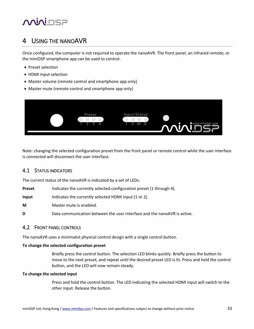
4.1 STATUS INDICATORS
The current status of the nanoAVR is indicated by a set of LEDs:
Preset Indicates the currently selected configuration preset (1 through 4).
Input Indicates the currently selected HDMI input (1 or 2).
M Master mute is enabled.
D Data communication between the user interface and the nanoAVR is active.
4.2 FRONT PANEL CONTROLS
The nanoAVR uses a minimalist physical control design with a single control button.
To change the selected configuration preset
Briefly press the control button. The selection LED blinks quickly. Briefly press the button to
move to the next preset, and repeat until the desired preset LED is lit. Press and hold the control
button, and the LED will now remain steady.
To change the selected input
Press and hold the control button. The LED indicating the selected HDMI input will switch to the
other input. Release the button.
miniDSP Ltd, Hong Kong / www.minidsp.com / Features and specifications subject to change without prior notice 34
4.3 INFRARED REMOTE CONTROL
Many standard and programmable remote control units can be used with the nanoAVR. Instead of adding
another remote to your collection, the nanoAVR can “learn” the control codes of your current remote if it
supports one of the following remote control codes:
NEC
Sony
Philips RC6
Apple Remote
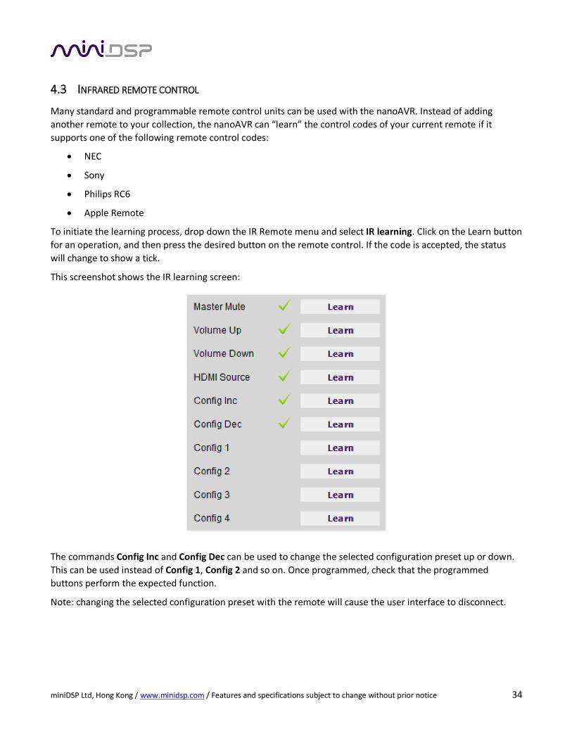
To initiate the learning process, drop down the IR Remote menu and select IR learning. Click on the Learn button
for an operation, and then press the desired button on the remote control. If the code is accepted, the status
will change to show a tick.
This screenshot shows the IR learning screen:
The commands Config Inc and Config Dec can be used to change the selected configuration preset up or down.
This can be used instead of Config 1, Config 2 and so on. Once programmed, check that the programmed
buttons perform the expected function.
Note: changing the selected configuration preset with the remote will cause the user interface to disconnect.
miniDSP Ltd, Hong Kong / www.minidsp.com / Features and specifications subject to change without prior notice 35
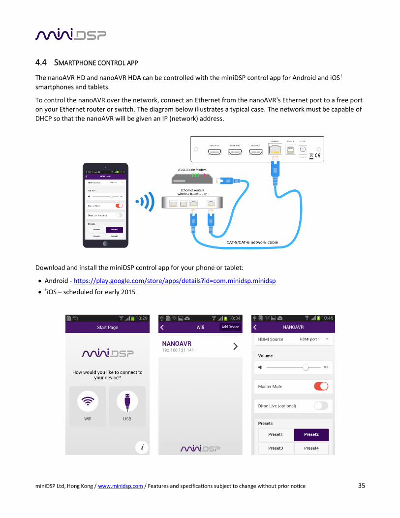
4.4 SMARTPHONE CONTROL APP
The nanoAVR HD and nanoAVR HDA can be controlled with the miniDSP control app for Android and iOS†
smartphones and tablets.
To control the nanoAVR over the network, connect an Ethernet from the nanoAVR's Ethernet port to a free port
on your Ethernet router or switch. The diagram below illustrates a typical case. The network must be capable of
DHCP so that the nanoAVR will be given an IP (network) address.
Download and install the miniDSP control app for your phone or tablet:
Android - https://play.google.com/store/apps/details?id=com.minidsp.minidsp
†iOS – scheduled for early 2015
miniDSP Ltd, Hong Kong / www.minidsp.com / Features and specifications subject to change without prior notice 36
5 ACOUSTIC MEASUREMENT
To obtain most accurate equalization results with the nanoAVR, acoustic measurement will be required. This
section provides a brief introduction. For more information, see the Applications section of the miniDSP.com
website.
5.1 WHAT IS ACOUSTIC MEASUREMENT?
An audio or home theater system has a frequency response on each channel, which includes the response of the
electronics, the loudspeaker, and the listening room. In order to understand how these all combine to affect the
sound heard by listeners, an acoustic measurement using a suitable microphone and computer software is
required.
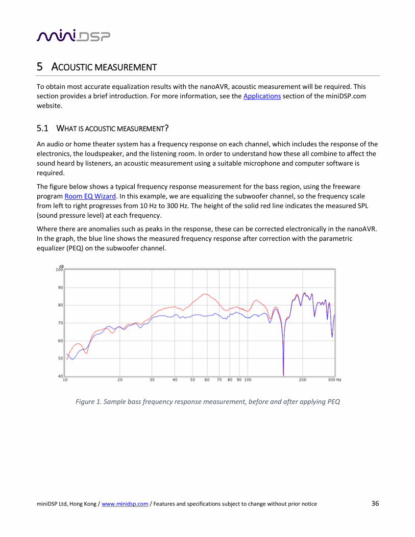
The figure below shows a typical frequency response measurement for the bass region, using the freeware
program Room EQ Wizard. In this example, we are equalizing the subwoofer channel, so the frequency scale
from left to right progresses from 10 Hz to 300 Hz. The height of the solid red line indicates the measured SPL
(sound pressure level) at each frequency.
Where there are anomalies such as peaks in the response, these can be corrected electronically in the nanoAVR.
In the graph, the blue line shows the measured frequency response after correction with the parametric
equalizer (PEQ) on the subwoofer channel.
Figure 1. Sample bass frequency response measurement, before and after applying PEQ
miniDSP Ltd, Hong Kong / www.minidsp.com / Features and specifications subject to change without prior notice 37
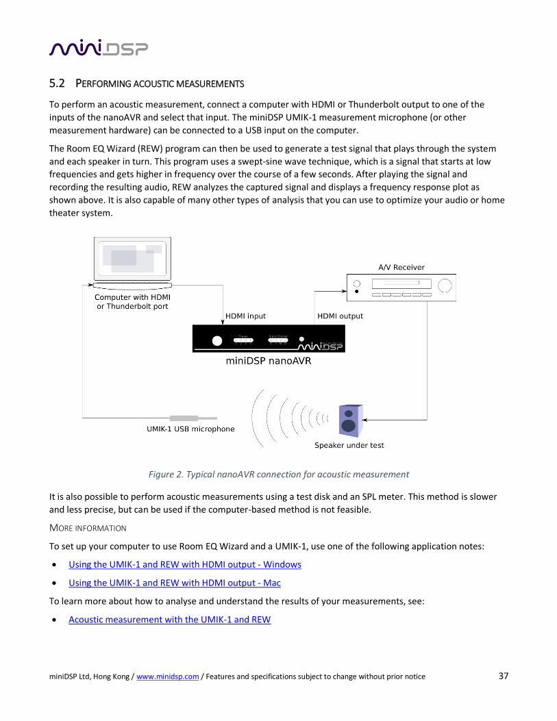
5.2 PERFORMING ACOUSTIC MEASUREMENTS
To perform an acoustic measurement, connect a computer with HDMI or Thunderbolt output to one of the
inputs of the nanoAVR and select that input. The miniDSP UMIK-1 measurement microphone (or other
measurement hardware) can be connected to a USB input on the computer.
The Room EQ Wizard (REW) program can then be used to generate a test signal that plays through the system
and each speaker in turn. This program uses a swept-sine wave technique, which is a signal that starts at low
frequencies and gets higher in frequency over the course of a few seconds. After playing the signal and
recording the resulting audio, REW analyzes the captured signal and displays a frequency response plot as
shown above. It is also capable of many other types of analysis that you can use to optimize your audio or home
theater system.
Figure 2. Typical nanoAVR connection for acoustic measurement
It is also possible to perform acoustic measurements using a test disk and an SPL meter. This method is slower
and less precise, but can be used if the computer-based method is not feasible.
MORE INFORMATION
To set up your computer to use Room EQ Wizard and a UMIK-1, use one of the following application notes:
Using the UMIK-1 and REW with HDMI output - Windows
Using the UMIK-1 and REW with HDMI output - Mac
To learn more about how to analyse and understand the results of your measurements, see:
Acoustic measurement with the UMIK-1 and REW
miniDSP Ltd, Hong Kong / www.minidsp.com / Features and specifications subject to change without prior notice 38
5.3 ADJUSTING EQUALIZER SETTINGS
Once a frequency response plot of a channel has been obtained, the parametric equalizers (PEQ) on that
channel can be used to adjust or correct the frequency response. In addition, the PEQ can be used to tailor the
sound to preference. For example, many listeners prefer an elevated bass to a “flat” response.
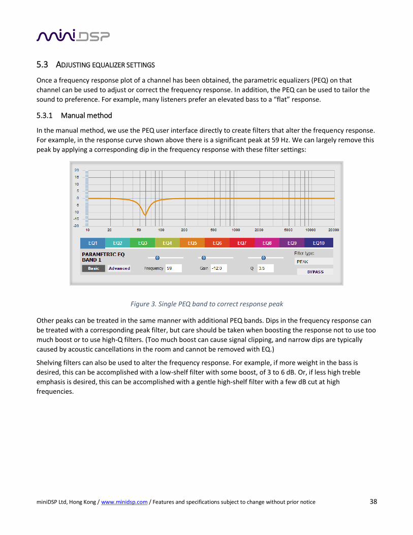
5.3.1 Manual method
In the manual method, we use the PEQ user interface directly to create filters that alter the frequency response.
For example, in the response curve shown above there is a significant peak at 59 Hz. We can largely remove this
peak by applying a corresponding dip in the frequency response with these filter settings:
Figure 3. Single PEQ band to correct response peak
Other peaks can be treated in the same manner with additional PEQ bands. Dips in the frequency response can
be treated with a corresponding peak filter, but care should be taken when boosting the response not to use too
much boost or to use high-Q filters. (Too much boost can cause signal clipping, and narrow dips are typically
caused by acoustic cancellations in the room and cannot be removed with EQ.)
Shelving filters can also be used to alter the frequency response. For example, if more weight in the bass is
desired, this can be accomplished with a low-shelf filter with some boost, of 3 to 6 dB. Or, if less high treble
emphasis is desired, this can be accomplished with a gentle high-shelf filter with a few dB cut at high
frequencies.
miniDSP Ltd, Hong Kong / www.minidsp.com / Features and specifications subject to change without prior notice 39
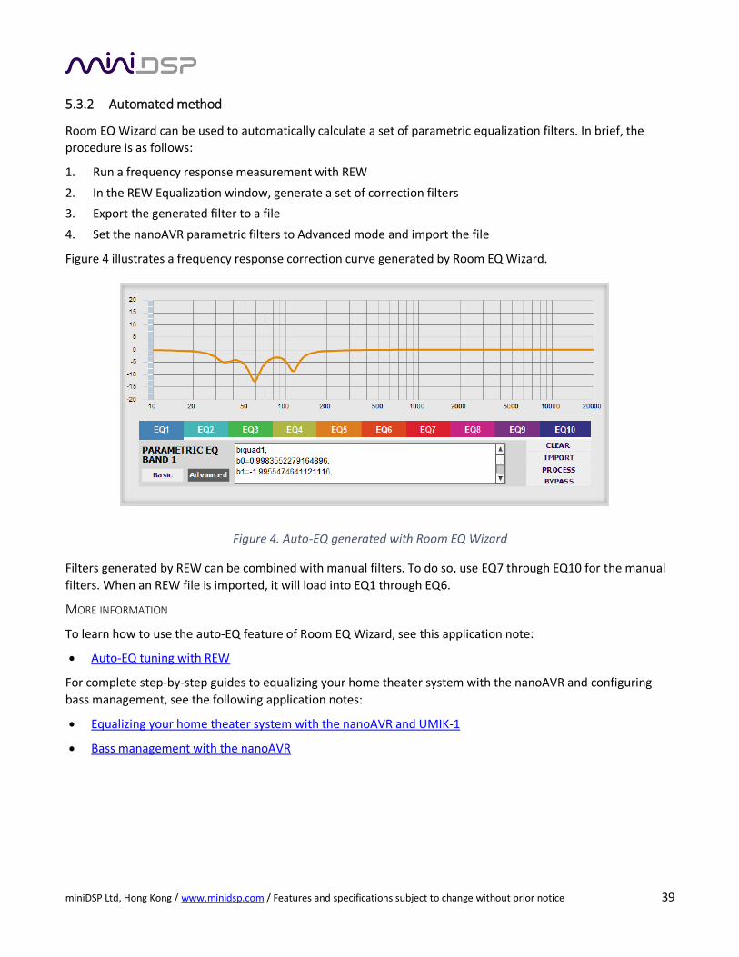
5.3.2 Automated method
Room EQ Wizard can be used to automatically calculate a set of parametric equalization filters. In brief, the
procedure is as follows:
1. Run a frequency response measurement with REW
2. In the REW Equalization window, generate a set of correction filters
3. Export the generated filter to a file
4. Set the nanoAVR parametric filters to Advanced mode and import the file
Figure 4 illustrates a frequency response correction curve generated by Room EQ Wizard.
Figure 4. Auto-EQ generated with Room EQ Wizard
Filters generated by REW can be combined with manual filters. To do so, use EQ7 through EQ10 for the manual
filters. When an REW file is imported, it will load into EQ1 through EQ6.
MORE INFORMATION
To learn how to use the auto-EQ feature of Room EQ Wizard, see this application note:
Auto-EQ tuning with REW
For complete step-by-step guides to equalizing your home theater system with the nanoAVR and configuring
bass management, see the following application notes:
Equalizing your home theater system with the nanoAVR and UMIK-1
Bass management with the nanoAVR
miniDSP Ltd, Hong Kong / www.minidsp.com / Features and specifications subject to change without prior notice 40
6 ADDITIONAL INFORMATION
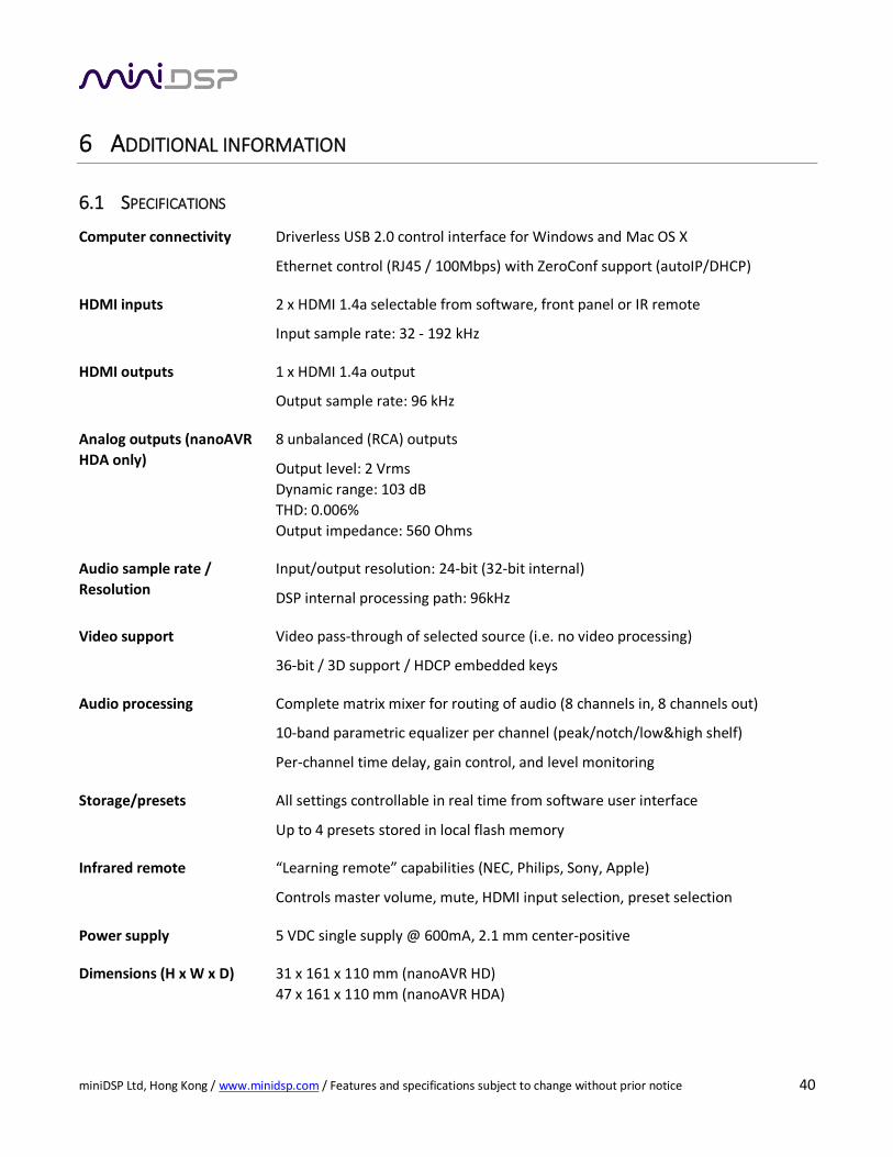
6.1 SPECIFICATIONS
Computer connectivity Driverless USB 2.0 control interface for Windows and Mac OS X
Ethernet control (RJ45 / 100Mbps) with ZeroConf support (autoIP/DHCP)
HDMI inputs 2 x HDMI 1.4a selectable from software, front panel or IR remote
Input sample rate: 32 - 192 kHz
HDMI outputs 1 x HDMI 1.4a output
Output sample rate: 96 kHz
Analog outputs (nanoAVR
HDA only)
8 unbalanced (RCA) outputs
Output level: 2 Vrms
Dynamic range: 103 dB
THD: 0.006%
Output impedance: 560 Ohms
Audio sample rate /
Resolution
Input/output resolution: 24-bit (32-bit internal)
DSP internal processing path: 96kHz
Video support Video pass-through of selected source (i.e. no video processing)
36-bit / 3D support / HDCP embedded keys
Audio processing Complete matrix mixer for routing of audio (8 channels in, 8 channels out)
10-band parametric equalizer per channel (peak/notch/low&high shelf)
Per-channel time delay, gain control, and level monitoring
Storage/presets
All settings controllable in real time from software user interface
Up to 4 presets stored in local flash memory
Infrared remote “Learning remote” capabilities (NEC, Philips, Sony, Apple)
Controls master volume, mute, HDMI input selection, preset selection
Power supply 5 VDC single supply @ 600mA, 2.1 mm center-positive
Dimensions (H x W x D) 31 x 161 x 110 mm (nanoAVR HD)
47 x 161 x 110 mm (nanoAVR HDA)
miniDSP Ltd, Hong Kong / www.minidsp.com / Features and specifications subject to change without prior notice 41
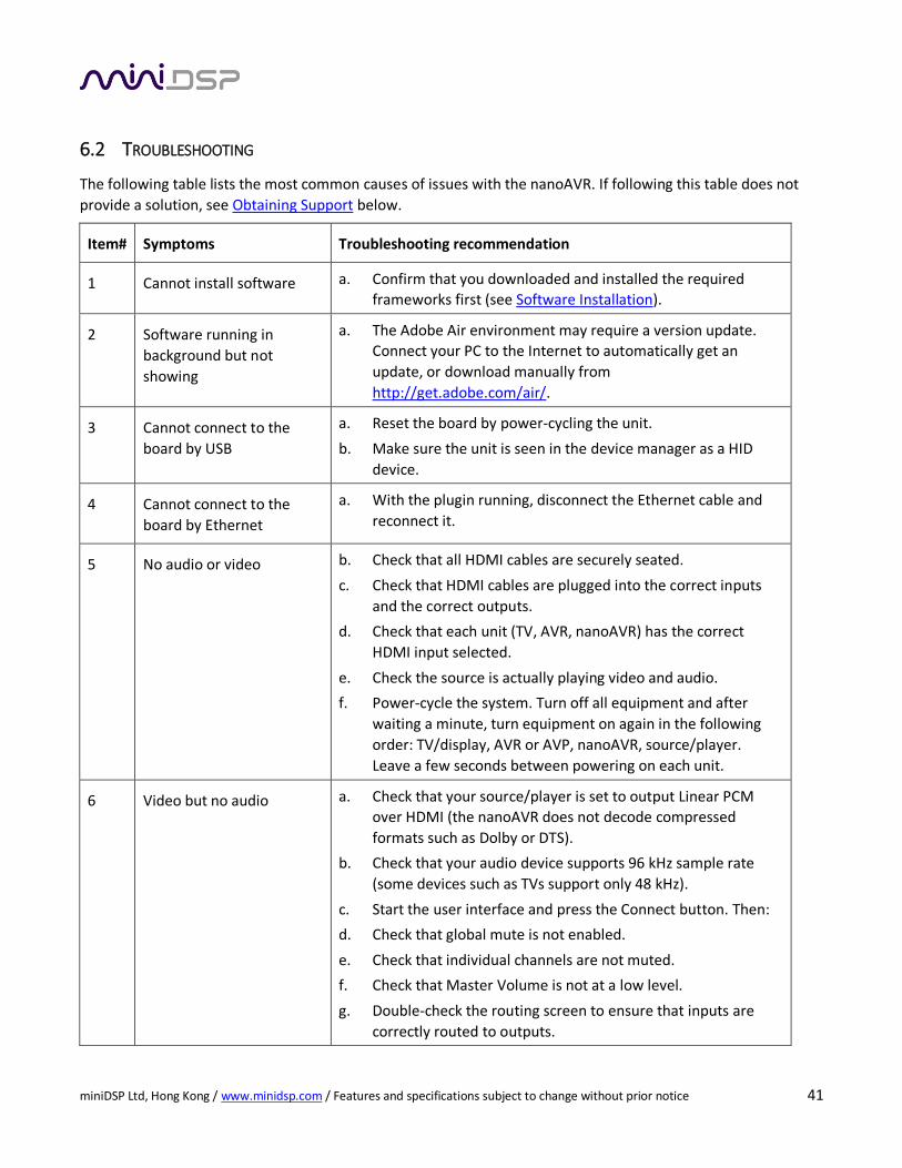
6.2 TROUBLESHOOTING
The following table lists the most common causes of issues with the nanoAVR. If following this table does not
provide a solution, see Obtaining Support below.
Item# Symptoms Troubleshooting recommendation
1 Cannot install software a. Confirm that you downloaded and installed the required
frameworks first (see Software Installation).
2 Software running in
background but not
showing
a. The Adobe Air environment may require a version update.
Connect your PC to the Internet to automatically get an
update, or download manually from
http://get.adobe.com/air/.
3 Cannot connect to the
board by USB
a. Reset the board by power-cycling the unit.
b. Make sure the unit is seen in the device manager as a HID
device.
4 Cannot connect to the
board by Ethernet
a. With the plugin running, disconnect the Ethernet cable and
reconnect it.
5 No audio or video b. Check that all HDMI cables are securely seated.
c. Check that HDMI cables are plugged into the correct inputs
and the correct outputs.
d. Check that each unit (TV, AVR, nanoAVR) has the correct
HDMI input selected.
e. Check the source is actually playing video and audio.
f. Power-cycle the system. Turn off all equipment and after
waiting a minute, turn equipment on again in the following
order: TV/display, AVR or AVP, nanoAVR, source/player.
Leave a few seconds between powering on each unit.
6 Video but no audio a. Check that your source/player is set to output Linear PCM
over HDMI (the nanoAVR does not decode compressed
formats such as Dolby or DTS).
b. Check that your audio device supports 96 kHz sample rate
(some devices such as TVs support only 48 kHz).
c. Start the user interface and press the Connect button. Then:
d. Check that global mute is not enabled.
e. Check that individual channels are not muted.
f. Check that Master Volume is not at a low level.
g. Double-check the routing screen to ensure that inputs are
correctly routed to outputs.
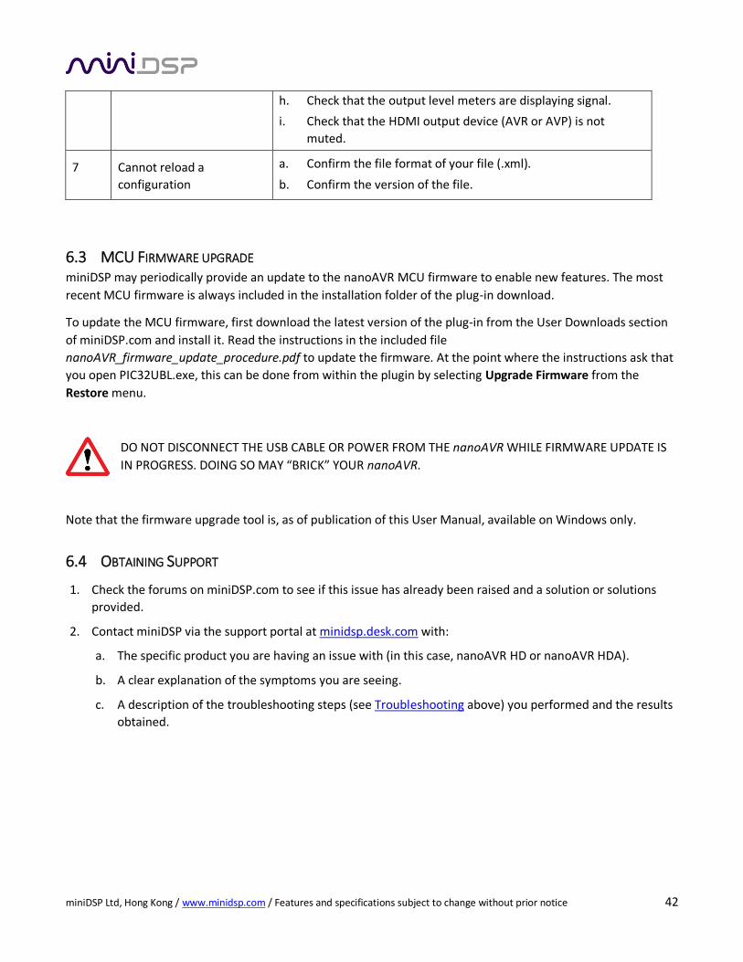
miniDSP Ltd, Hong Kong / www.minidsp.com / Features and specifications subject to change without prior notice 42
h. Check that the output level meters are displaying signal.
i. Check that the HDMI output device (AVR or AVP) is not
muted.
7 Cannot reload a
configuration
a. Confirm the file format of your file (.xml).
b. Confirm the version of the file.
6.3 MCU FIRMWARE UPGRADE miniDSP may periodically provide an update to the nanoAVR MCU firmware to enable new features. The most
recent MCU firmware is always included in the installation folder of the plug-in download.
To update the MCU firmware, first download the latest version of the plug-in from the User Downloads section
of miniDSP.com and install it. Read the instructions in the included file
nanoAVR_firmware_update_procedure.pdf to update the firmware. At the point where the instructions ask that
you open PIC32UBL.exe, this can be done from within the plugin by selecting Upgrade Firmware from the
Restore menu.
DO NOT DISCONNECT THE USB CABLE OR POWER FROM THE nanoAVR WHILE FIRMWARE UPDATE IS
IN PROGRESS. DOING SO MAY “BRICK” YOUR nanoAVR.
Note that the firmware upgrade tool is, as of publication of this User Manual, available on Windows only.
6.4 OBTAINING SUPPORT
1. Check the forums on miniDSP.com to see if this issue has already been raised and a solution or solutions
provided.
2. Contact miniDSP via the support portal at minidsp.desk.com with:
a. The specific product you are having an issue with (in this case, nanoAVR HD or nanoAVR HDA).
b. A clear explanation of the symptoms you are seeing.
c. A description of the troubleshooting steps (see Troubleshooting above) you performed and the results
obtained.