Embed Size (px)
Citation preview

600.455/655 Fall 2020 1 of 7
Homework Assignment 4 – 600.455/655 Fall 2020 (Circle One) Instructions and Score Sheet (hand in with answers)
Name Name
Email Email
Other contact information (optional) Other contact information (optional)
Signature (required) I/We have followed the rules in completing this assignment _____________________________
Signature (required) I/We have followed the rules in completing this assignment _____________________________
Question Points (455,655) Totals
1A 5 1B 5 1D 5 1D 10 25 2A 5 2B 5 2C 5 2D 5 20 2E 25 2F 20 2G 15 2H 15 75
Total 120 (100 max)

600.455/655 Fall 2020 2 of 7
1. Remember that this is a graded homework assignment. It is the functional equivalent of a take-home exam.
2. You are to work alone or in teams of two and are not to discuss the problems with anyone other than the TAs or the instructor.
3. It is otherwise open book, notes, and web. But you should cite any references you consult. 4. Please refer to the course organizational notes for a fuller listing of all the rules. I am not reciting
them all here, but they are still in effect. 5. Unless I say otherwise in class, it is due before the start of class on the due date posted on the web. 6. Sign and hand in the score sheet as the first sheet of your assignment. 7. Submit your answers to GradeScope 8. In your answers, also include a brief statement of who did what.
600.455/655 Fall 2020 3 of 7
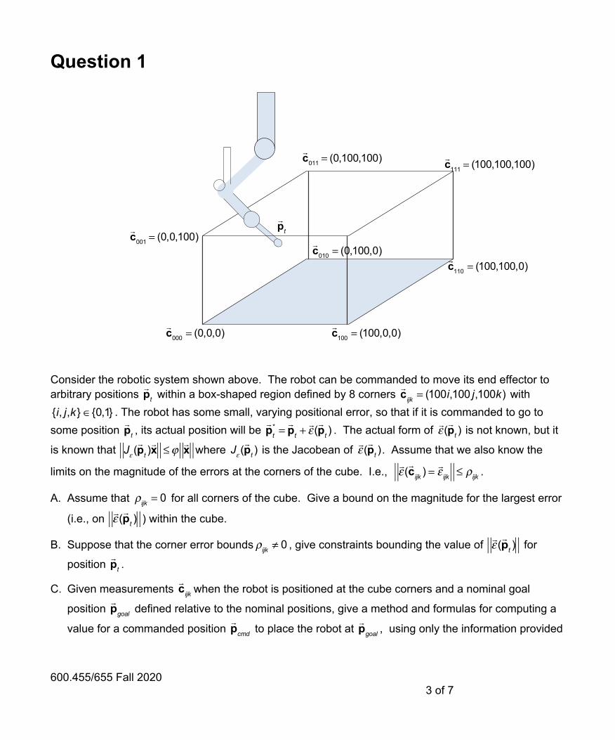
Question 1
Consider the robotic system shown above. The robot can be commanded to move its end effector to arbitrary positions within a box-shaped region defined by 8 corners with
. The robot has some small, varying positional error, so that if it is commanded to go to some position , its actual position will be . The actual form of is not known, but it
is known that where is the Jacobean of . Assume that we also know the
limits on the magnitude of the errors at the corners of the cube. I.e., .
A. Assume that for all corners of the cube. Give a bound on the magnitude for the largest error
(i.e., on ) within the cube.
B. Suppose that the corner error bounds , give constraints bounding the value of for
position .
C. Given measurements when the robot is positioned at the cube corners and a nominal goal
position defined relative to the nominal positions, give a method and formulas for computing a
value for a commanded position to place the robot at , using only the information provided
!pt
!c000 = (0,0,0)
!c100 = (100,0,0)
!c010 = (0,100,0) !
c110 = (100,100,0)
!c011 = (0,100,100)
!c001 = (0,0,100)
!c111 = (100,100,100)
!pt
!cijk = (100i,100 j,100k)
{i, j,k} ∈{0,1}!pt
!pt* =!pt +!ε (!pt )
!ε (!pt )
Jε (!pt )!x ≤ϕ
!x Jε (
!pt )
!ε (!pt )
!ε (!cijk ) =
!ε ijk ≤ ρijk
ρijk = 0!ε (!pt )
ρijk ≠ 0!ε (!pt )
!pt
!cijk
!pgoal
!pcmd
!pgoal

600.455/655 Fall 2020 4 of 7
here. Hint: Note that this is a sort of calibration problem. There is not enough information to place the robot exactly where it is to go, but one can do better than simply setting .
D. Suppose that the robot’s position at two points and at a fairly large distance apart within the cube has been measured to high accuracy, with and . If the robot is now
commanded to move on a straight line path between and , give a bound on the worst case deviation from the desired path. For what value of is this bound the loosest?
!pcmd =
!pgoal
!a
!b
!ε (!a) ≤ δa
!ε (!b) ≤ δb
!pt =
!a + λ(
!b −!a) for 0 ≤ λ ≤1
!a
!b
λ

600.455/655 Fall 2020 5 of 7
Question 2
Consider the situation shown in the figure above. Here, a robot is inserting an articulated tool into a
polyhedral hole. The robot is equipped with a 6 DOF force sensor between the tool holder and the rest of the robot. The pose of the tool holder with respect to the base of the robot is given by
. The position of the articulation point relative to the tool holder is given by and the position of the tool tip relative to the tool holder is given by
where is the bend angle. The tool shaft does not rotate relative to the tool holder. For now, you can assume that is fixed. The tool shaft has a diameter and the articulation point of the tool is surrounded by a ball of diameter and the tool tip consists of a ball cutter with diameter .
The robot force sensor reports forces and torques resolved in the coordinate system of the tool holder. Sometimes we may find it convenient to refer to the combined force/torque vector . The robot kinematics for joint positions are known and a “left side” Jacobean is available such that with . We can also express
with the combined incremental motion vector , with
Fw
!C(!x)
!h jtop
!h j+1top
!h jbottom
!h j+1bottom
!n j
!h jtop =!h jbottom + [0,0,100]T
6 DOF force Sensor
!pwa
!pwb =
!pwa + [Lb cosθ,Lb sinθ,0]
T
!ψ(!x)
Fw (!q) = [Rw (
!q),!pw (!q)]
!pwa = [0,0,−La ]
T
!pwb =
!pwa + [Lb cosθ,Lb sinθ,0]
T θ
θ 2rshaft2ra
2rb!f
!τ!η = [!f T ,!τ T ]T
Fw (!q) = Kinsw (
!q)
!q JW
left (!q)
Fw (!q+ Δ
!q) = ΔFw
left (!q,Δ!q)Fw (
!q) ΔFw
left (!q,Δ!q) ≈ Jw
left (!q)Δ!q
ΔFwleft ≈ [I+ sk( !αw
left ),!εwleft ]
!φwleft =
!αwleft( )T , !εwleft( )T⎡
⎣⎢⎤⎦⎥
T

600.455/655 Fall 2020 6 of 7
corresponding definitions for a “right hand side” incremental motion , with .
The sides of the hole are defined by planes connecting polygonal curves defining the top and bottom of the hole. The top and bottom polygonal curves are parallel and defined by their vertices and
for , with , with all vertex coordinates expressed relative to the base
frame of the robot. Each facet of the hole corresponds to the vertices and is
associated with a planar constraint where is the outward facing normal of the facet from the hole.
In addition, there is a desired cutter path defined relative to the base frame of the robot. Further, you can assume that a function is available giving the tangent unit vector direction for any point on the cutter path and that a function is available giving the closest point on for any point in space.
A. (Not referring to the figure). Given two line segments and defined by their endpoints, explain how to compute the closest distance between any points on and , together with the corresponding points and on each line segment.
B. Give formulas for computing the positions of the tool articulation point and of the cutter ball relative to the base coordinate system of the robot.
C. Give a formula for a “right side” Jacobean such that with , based on and .
D. Give formulas for computing the and .
E. A simple “admittance” control law for force compliance can be implemented by solving the constrained least squares problem:
at every sample interval in the robot’s mid-level controller and outputting velocity commands , where is the sample interval time. Explain how to extend this formulation to
guarantee that no part of the tool shaft or tool articulation point intersects the hole when the tool is inserted into the hole by a distance exceeding . Here you may assume that you have correct answers to Questions 3A-D, so you may use entities such as and and you can invoke the algorithm implied by Question 2A, if these seem appropriate. Hint: You may find it useful to express part of your answer in terms of and include the appropriate Jacobean formulas for their motion.
ΔFwright (!q,Δ!q)
Fw (!q+ Δ
!q) = Fw (
!q)ΔFw
right (!q,Δ!q)
!h jbottom
!h jtop
j = 1,!,Nsides!h jtop =!h jbottom + [0,0,100]T
j!h jbottom,
!h j+1bottom,
!h jtop,!h j+1top
!n j i!x ≤ d j
!n j
C!Ψ(!x)
!x
!c =Closest(C,
!p)
!c C
!p
A = [!a0,!a1] B = [
!b 0,!b1]
dAB A B!ac
!bc
!pa(!q)
!pb(!q)
JWright (!q) Fw (
!q+ Δ
!q) = Fw (
!q)ΔFw
right (!q,Δ!q)
ΔFwright (!q,Δ!q) ≈ Jw
right (!q)Δ!q JW
left (!q) Fw (
!q)
!n j d j
Δ!q = argmin
Δ!q
φwright −K !η
2
φwright = Jw
right (!q)Δ!q
!"q = Δ!q / ΔT ΔT
2ra!n j d j
!pa(!q)

600.455/655 Fall 2020 7 of 7
F. Explain how you would extend your answer to Question 2E to ensure that the center of the ball cutter stays as close as possible to the center of the desired cutter path and always stays within a distance of the path. You can assume that staying on the path is 10 times more important that following forces pulling the tool off the path. Hint: You may find it useful to express part of your answer in terms of and and to include the appropriate Jacobean formulas for their motion.
G. Suppose that hand-over hand guiding has been replaced by autonomous control such that the ball cutter is to traverse a sequence of set points along the cutter path while avoiding contact with the hole as in Question 3E. Suppose that the mid-level controller can generate a set point at every time tick t. Describe an optimization problem that will produce the desired behavior.
H. Suppose now that the tool’s shape is controllable, so that the computer can control the values of and . Further, suppose that it is desirable to minimize the motion of the main robot’s joints as much as possible, consistent with the other goals of the surgical task. Further, it is 10 times more important to maintain than . How would you modify your answer to Question 3G in order to take advantage of this redundant motion capability, consistent with these other requirements?
ρ
!pa(!q)
!pb(!q)
!ct
LAθ
Rw
!pw