Embed Size (px)
Citation preview

1 © 2012 Calix
The information contained in this presentation is not a commitment, promise, or legal obligation
to deliver any material, code, or functionality. The development, release, and timing of any
features or functionality described for our products remain at our sole discretion.
Homeworx Lessons?
What can we learn from the first deployment of OFDMA on HFC?
Hal Roberts, Calix

2 © 2012 Calix
Supporters
Eugene Dai – Cox Communications

3 © 2012 Calix
Started as a pure PON System ADC Telecom proprietary PON named “Homeworx”
Based on British Telecom’s PON (built by BT’s
manufacturing arm, Fulcrum)
MAC used TDMA on a bit interleaved basis.
PHY as same as EPON/GPON, OOK (on/off keying)
Designed to carry circuit switched traffic
Telephony (DS0s) and ISDN
Trials with Pacific Bell circa 1990-1991
RBOC interest in PON collapsed based on regulatory changes and
desire to compete with cable operators for video
CableLabs/Time Warner Visit circa 1992
Alexander Futro (CL) and David Pangrac (TW) visit ADC
Homeworx lab looking for a solution for Voice over Cable
ADC proposed converting optical transceivers in Homeworx PON
to RF transceivers for HFC

4 © 2012 Calix
Homeworx HFC “TDMA Phase” Initial Approach
Retain PON TDM/TDMA MAC
Modify PHY layer only (sound familiar?)
But Bit Interleaved MAC layer prevents EPoC style PHY
Bit Interleaved TDMA
Eliminated any possibility of Multi-Bit Symbols, QPSK, QAM-16
etc.
RF Modulation “Solution”
“Shaped” OOK
Subject to: Group Delay and Multipath
Leading to: Inter-Symbol Interference (ISI)
Successful Trial with Rochester Telephone
ISI ‘fixed’ by deleting every other bit
But used too much upstream bandwidth – 20MHz
0
ONU1
1
ONU2
0
ONU3
0
ONU4
1
ONU5
1
ONU6
0
ONU7
1
ONU8
1
ONU32
5 © 2012 Calix
Homeworx HFC “OFDM Phase” Looking to go from worst spectral efficiency to first
MSOs cannot give 20MHz in Upstream
Only 37MHz total and about 20MHz ‘clean’
Spectral efficiency needed large improvement
Search for Efficient/Robust PHY led to OFDM
OFDM allows carriers with no guard bands (efficient)
Individual Sub-Carriers (Tones) mitigate Amplitude Ripple
Cyclic Prefix mitigates Group Delay and Multipath
Control Channels and Data can be on different Sub-Carriers with
different QAM (for robustness)
Long Symbol Durations mitigate Impulse Noise FEC used for large/long impulse noise
Multipoint to Point OFDM on HFC led to first use of OFDMA
OFDMA has significant efficiency advantages
Required solving distributed synchronization problem

6 © 2012 Calix
Homeworx Channel Model Simple Model
Specification
Forward,
Optics and Coax
Reverse,
Optics and Coax
Maximum RF gain rate of change (without need for re-ranging) <1dB / 1 sec <1dB / 10 min.
Impedance 75 75
SNR 38 dB
recommended
See Table “A”
CSO or CTB -52 dBc
recommended
N/A See narrow-band
ingress table
Differential Group Delay over 6 MHz band 1.2us 1.2us
Narrowband Interference Levels, loss of SCs per interference spurs
(without R-S error correction), “Loss” of SC defined as a BER of 1E-5.
Interference levels below are measured with respect to single DS0 level.
Narrowband is assumed to be <25kHz
+14 to +24 dBc
+4 to +14 dBc
-6 to +4 dBc
-16 to -6 dBc
-26 to -16 dBc
-36 to -26 dBc
Lost SCs
225
70
7-22
3-7
1-3
0-1
Lost SCs
225
70
7-22
3-7
1-3
0-1
Multipath -10dBc @ 0.5us
-20dBc @ 1.0us
-30dBc @ 2.0us
-10dBc @ 0.5us
-20dBc @ 1.0us
-30dBc @ 2.0us
Common Path Distortion See table for
Narrowband
Interference above
See table for
Narrowband Interference
above
Phase Noise N/A assuming no
block frequency
conversion in the
forward path.
<-70dBc/Hz@10Hz
<-90dBc/Hz@100Hz
<-94dBc/Hz@1kHz
<-100dBc/Hz@10kHz
<-130dBc/Hz@100kHz

7 © 2012 Calix
Homeworx OFDM “Numerology”
6MHz OFDM Channel – 552 Sub-Carriers
Required first 1024 pt. FFT custom ASIC
Symbol Duration
125 microseconds
Sub-Carrier Spacing
9kHz
Cyclic Prefix
12.5 microseconds (probably overkill)
Modulation
BPSK, QAM-4 (QPSK), QAM-32
FEC
Reed-Salomon
41 byte codeword
~ 20% Overhead

8 © 2012 Calix
Homeworx Sub-Carrier Map 552 Subcarriers
Called ‘tones’ in this diagram
Payload, Control (IOC) and Sync SCs
Payload modulated at QAM-32 (later QAM-4 or QPSK)
Control, Sync Modulated BPSK
SCs were dedicated, payload, sync and control SCs did not switch
Rev 1 - Payload QAM-32 Only, no MCS
Rev 2 - Payload QAM-4/32 MCS (DC-OFDM or “Dual Constellation”)
One Single Family Modem
Max OFDMA Tx
240 simultaneous
Remote
transmitters

9 © 2012 Calix
Homeworx Frame Structure
Time
Frequency
Frame in Time is converted to Frequency

10 © 2012 Calix
QAM-32 Constellation Map Note: Upstream HFC at this time was QPSK at best
Upstream Downstream Rates Symmetrical
QAM level based on upstream impairments
QAM in DS based on US
QAM-32 in Homeworx
QAM-32 (vs 16 or 64) used as two
sub-carriers could carry 1 DSO +
FEC/Signaling
Predates QAM-16 in DOCSIS
Highest upstream efficiency until
DOCSIS 2.0 released Dec 2001
QAM-4 (QPSK) added for data
channels circa 1999
Called DC-OFDM for “Dual
Constellation”

11 © 2012 Calix
Scanning and Synchronization
Remote modem scanned every 2 MHz till OFDM sync
detected
Covers both 6 MHz and 8 MHz plans
Symbol Rate and Channel Frequency are locked at Headend
Modem
When remote modem locks to
Two ‘Sync’ Channels in the Downstream
BPSK - Separated from Data Channels for fast Sync
Two for redundancy, if Primary had ingress go to Secondary
Synchronization of Carrier Frequency/Symbol Rate are done on Sync
tone
Derotation of BPSK to adjust phase
Remote goes to predefined IOC (ISU Operations Channel) to track via
keeping BPSK in phase in I/Q plane

12 © 2012 Calix
Ranging
Downstream and Upstream Carriers Locked at Headend
Therefore once the Remote modem is downstream synced, upstream
is automatically locked (no Doppler shift to be concerned with)
Ranging
For amplitude and phase adjustment only
Remote transmitter uses one of two upstream ranging subcarriers
Ranging SC is separated from Data SCs (not orthogonal until ranging)
Amplitude is adjusted in coarse and fine steps
Phase offset measured and Headend modem transmit phase offset to
Remote modem
Derotation of BPSK and QAM-32 done and tracked in headend
modem reciever
Periodic Amplitude and Phase Adjustment
Done via IOC transmissions on periodic basis.
All OFDMA carriers are transmitted at the same level from remote (i.e.
no amplitude equalization).
13 © 2012 Calix
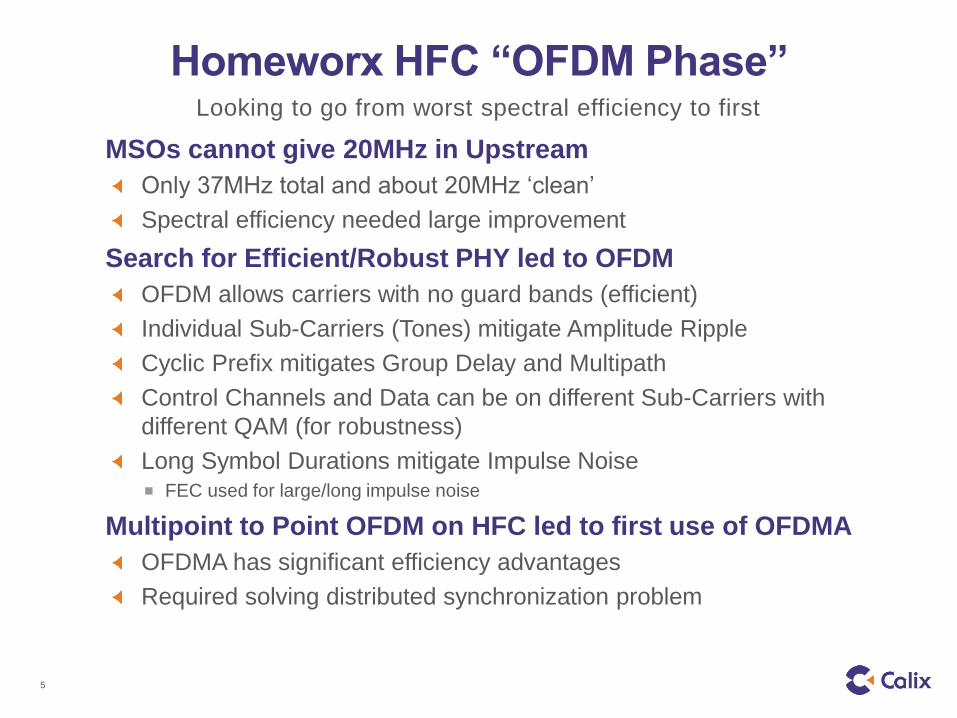
Homeworx Deployments Starting in 1997 to ~2007
400K+ OFDM Modems (HISUs)
> 1,000,000 Phone Lines
Customers
Largest Operators OptusVision
MediaOne/AT&T -> Comcast
Adelphia
Smaller Operators Wide Open West etc.

14 © 2012 Calix
Why wasn’t the first cable OFDMA system
a Commercial Success? Fundamentally a Switched Circuit based platform
World was moving away from switched circuit
Switching to Packet Based required fundamental redesign of all
cards
“Bleeding Edge” Technology
FFT ASICs not available, required large number of custom ASICs
Higher Cost due to lack of standardized volume components.
Higher power consumption due to silicon technology status and
relatively high digital signal processing
QAM-32 seen as ‘fragile’, QAM-4 added late
Spectral Efficiency actually higher than needed
Homeworx system allowed 240 simultaneous DS0s (phone lines)
Consumers did not purchase multiple phone lines as expected
“Take rates” did not equal operator’s expectations
“Concentration” of phone lines reduces need for simultaneous
channels
15 © 2012 Calix
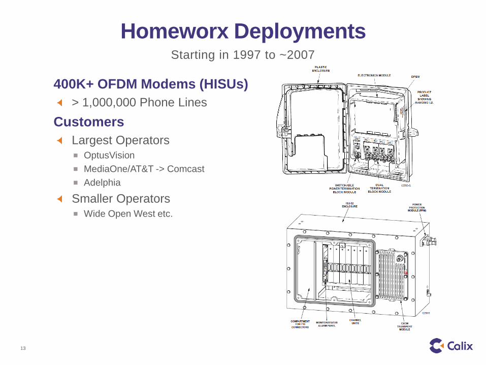
Homeworx Lessons? Right Multiplexing, Wrong QAM Level
OFDM using QAM-4 (first) would have been ideal choice
Faster time to market
Lower cost
Lower power
Add QAM-XX Later
Great pressure to add multiple modulations for higher
plant noise (security blanket)
QAM-4 added to QAM-32 for payload at high development cost
Operators never turned on QAM-4
Modems were ‘Right Sized’
Single-family unit demodulated and transmitted only 1/20th of
6MHz channel
Multi-family unit demodulated and transmitted ½ of 6MHz
Saved power and cost

16 © 2012 Calix
Homeworx Lessons?
Too many resources associated with one 6 MHz headend
channel which could not be redistributed
Low take rate plants still consumed entire headend modem
resources
Flexible distribution of resources essential
Ideal (for the time period) would be 2MHz per channel
No issues with Multipath or Group Delay
Cyclic Prefix of 12.5us eliminated impact of distortions
But 12.5us is probably too good (long) in retrospect
Complexity
Complex system (for its time)
KISS