Embed Size (px)
Citation preview
FCS - 1
Homologation is required of all FORMULA cars registered after January 1, 1983. Homologation forms must be on file with SCCA Inc., Topeka, Kansas for any car to be allowed to compete in any SCCA event. Homologation forms must be submitted to:
Sports Car Club Of America, Inc.Technical Services Department
Building 300, B StreetTopeka, Kansas 66619
Modifications may be made to a vehicle after it has been homologated as long as said modifications stay within the scope of the rules.
Homologation Fees
Formula Cars $75.00 (Per Chassis)
Replacement Certificates $200.00 Each
Special Handling Fee $45.00
A special handling fee shall be charged for any special attention over and above the normal processing time. Special handling is a twenty-four (24) hour turn around process, provided all documentation is in order. The certificate is returned via U.S. Postal Service first class mail. If overnight service is necessary, the express charges are not included in the special handling fee and shall be added to the fee.
17.1.6. FORMULA CATEGORYThese specifications are part of the SCCA General Competition Rules (GCR) and all automobiles shall conform with GCR Section 17., Automobiles.
The Formula Category is intended to provide the membership and interested manufacturers with the opportunity to compete in purpose built, highly modified open wheel single seat cars. The Club may alter or adjust specifications and require, permit, or restrict certain specific components to equate competitive potential.
A. FORMULA ATLANTIC PREPARATION RULESFormula Atlantic is a restricted class. Therefore, any allowable modifications, changes, or additions are as stated herein. There are no exceptions. Homologation is required for all cars registered after January 1, 1983.
New chassis of non-metallic composite construction shall be proven to meet FIA specifications for non-metallic composite chassis prior to being submitted to the SCCA for homologation. Contact the SCCA national office for a list of the relevant FIA specifications/SCCA requirements.
The SCCA shall publish Formula Atlantic Category Specifications containing the basic officially recognized specifications for each car eligible to compete in the Category during the calendar year. These classifications are listed in A.1.a.2
FCS - 2
A.1. Generala. A single seat, four open-wheeled racing car with firewall,
floor, and safety equipment conforming to GCR Section 17., “Automobiles/General Regulations.” Homologation is required for all cars registered after January 1, 1983. Alternate rollbar designs will be considered.
b. Cars shall be equipped with on-board self starter controlled by the driver in a normal driving position.
c. The driver’s seat shall be capable of being entered without the removal or manipulation of any part or panel (except for a removable steering wheel).
d. Cars shall be equipped with a dual braking system operated by a single control. In case of failure or leak at any point in the system, effective braking power shall be maintained on at least two wheels.
e. Superchargers or turbochargers are not permitted.
f. Power shall not be applied to more than two (2) wheels.
g. Bodywork:1. No part of the bodywork and aerodynamic devices shall
exceed in height a horizontal plane 90cm (35.4”) above the ground. The safety roll bar/roll cage and the engine air box are not included in this height restriction. Measurements are to be made as raced with driver on-board.
2. Behind the front wheels, the bodywork shall not exceed a maximum width of 130cm (51.18 inches) with the exception of lateral fuel tanks. The overall maximum width behind the front wheels to the leading edge of the rear wheels shall not exceed 130cm (51.18 inches). The maximum width of any aerodynamic device situated behind the front wheels, including the rear wing, shall not exceed 110cm (43.307 inches).
3. The bodywork ahead of the front wheels may be extended to an overall maximum width of 150cm (59.055 inches) provided it does not extend beyond the outside of the front tires. Flexible or movable aerodynamic skirts are prohibited. No part of the body or suspended part of the car shall extend more than 1cm (0.394 inches) below the horizontal plane forming the bottom of the tub or chassis floor (both static or in motion).
4. Any part of the bodywork ahead of the front wheels exceeding an overall width of 110cm (43.307 inches) shall not extend above the height of the front wheel rims.
5. Any specific part of the car which has an aerodynamic influence on the stability of the vehicle shall be mounted on
FCS - 3
the entirely sprung part of the car and shall be firmly fixed while the car is in motion. Aerodynamic devices, including wings and end plates, shall not extend to the rear more than one meter (39.4 inches) from the centerline of the rear wheel hubs.
6. Neither the safety roll bar nor any of the units associated with the functioning of the engine or transmission shall have an aerodynamic effect by creating a vertical thrust.
7. The leading edge of an airfoil fixed to the front of the car shall not be sharp. Minimum radius -- 1.5cm (0.06 inches).
8. The fuel filler cap shall be recessed within the coach-work line.
9. Cars registered with SCCA January 1, 1976, and after, shall be fitted with deformable structures per FIA regulations for Formula II as follows: Deformable Structure: The entire fuel tank area of the car licked by the airstream shall incorporate a crushable structure conforming to the following specifications. The term “licked by the airstream” is considered to define the complete external area of the body/monocoque construction irrespective of such added items as water radiators, inlet ducts, windscreens, etc..
A. The crushable structure shall be a sandwich construction based on a fire-resistant core of minimum crushing strength of twenty-five (25) lbs./ square inch. Water pipes are permitted to pass through this core. The sandwich construction shall include two (2) sheets of 1.5mm (.060”) thickness, one of which shall be aluminum sheet having a tensile strength of fourteen (14) tons/ square inch and a minimum elongation of five (5) percent.
B. The use of a magnesium sheet will be authorized only if its thickness exceeds 3mm (.120”).
C. The minimum thickness of the sandwich construction shall be 10mm (.3937”). The fore and aft fuel tank area, however, shall provide for a crushable structure of at least 100mm (3.937”) thickness at such crushable structure’s thickest point. The position of this widest point to be at the manufacturer’s discretion over a length of at least 35cm (13.78”) after which it may be gradually reduced to 10mm (.3937”).
10. The minimum wheel diameter is thirteen (13) inches. Ex-FSV cars are permitted front wheel width: minimum six (6) inches, maximum eight (8) inches; rear wheel width: minimum eight (8) inches, maximum ten (10) inches. All other cars front wheel width: ten (10) inches; rear wheel width: minimum fourteen (14) inches, maximum fifteen (15) inches.
FCS - 4
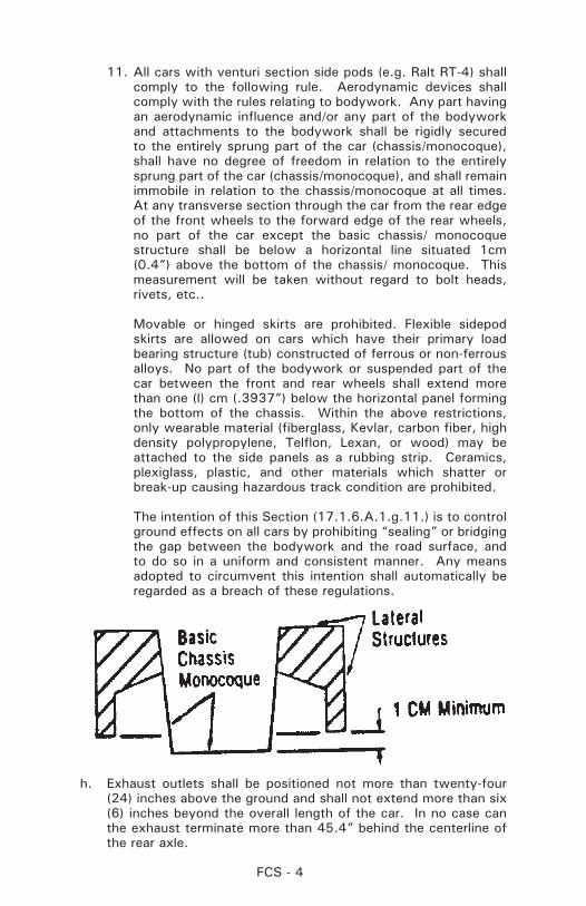
11. All cars with venturi section side pods (e.g. Ralt RT-4) shall comply to the following rule. Aerodynamic devices shall comply with the rules relating to bodywork. Any part having an aerodynamic influence and/or any part of the bodywork and attachments to the bodywork shall be rigidly secured to the entirely sprung part of the car (chassis/monocoque), shall have no degree of freedom in relation to the entirely sprung part of the car (chassis/monocoque), and shall remain immobile in relation to the chassis/monocoque at all times. At any transverse section through the car from the rear edge of the front wheels to the forward edge of the rear wheels, no part of the car except the basic chassis/ monocoque structure shall be below a horizontal line situated 1cm (0.4”) above the bottom of the chassis/ monocoque. This measurement will be taken without regard to bolt heads, rivets, etc..
Movable or hinged skirts are prohibited. Flexible sidepod skirts are allowed on cars which have their primary load bearing structure (tub) constructed of ferrous or non-ferrous alloys. No part of the bodywork or suspended part of the car between the front and rear wheels shall extend more than one (l) cm (.3937”) below the horizontal panel forming the bottom of the chassis. Within the above restrictions, only wearable material (fiberglass, Kevlar, carbon fiber, high density polypropylene, Telflon, Lexan, or wood) may be attached to the side panels as a rubbing strip. Ceramics, plexiglass, plastic, and other materials which shatter or break-up causing hazardous track condition are prohibited.
The intention of this Section (17.1.6.A.1.g.11.) is to control ground effects on all cars by prohibiting “sealing” or bridging the gap between the bodywork and the road surface, and to do so in a uniform and consistent manner. Any means adopted to circumvent this intention shall automatically be regarded as a breach of these regulations.
h. Exhaust outlets shall be positioned not more than twenty-four (24) inches above the ground and shall not extend more than six (6) inches beyond the overall length of the car. In no case can the exhaust terminate more than 45.4” behind the centerline of the rear axle.
FCS - 5
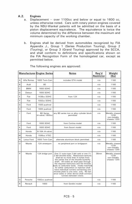
A.2. Enginesa. Displacement -- over 1100cc and below or equal to 1600 cc,
unless otherwise noted. Cars with rotary piston engines covered by the NSU-Wankel patents will be admitted on the basis of a piston displacement equivalence. The equivalence is twice the volume determined by the difference between the maximum and minimum capacity of the working chamber.
b. Engines shall be derived from automobiles recognized by FIA Appendix J., Group 1 (Series Production Touring), Group 2 (Touring), or Group 3 (Grand Touring) approved by the SCCA, and shall conform to definitions and specifications shown on the FIA Recognition Form of the homologated car, except as permitted below.
The following engines are approved:
Manufacturer Engine Series Notes Req’dRestrictor
Weight(lbs)
A Alfa Romeo 1600 Twin-Cam includes GTA model n/a 1160
B Audi 80 n/a 1160
C BMW 1600 SOHC n/a 1160
D Datsun 1600 SOHC n/a 1160
E Fiat 1438cc DOHC from 124 n/a 1160
F Fiat 1592cc DOHC n/a 1160
G Ford 1500 pushrod n/a 1160
H Ford 1600 pushrod n/a 1160
I Ford BD Series(4-valve) 1600cc
any BD series iron or alloy cylinder block permitted
n/a Metallic chassis 1230
non-metallic chassis 1255
J Ford 1600 SOHC from Cortina model n/a 1160
K Ford 1600 SOHC from Escort model n/a 1160
L Honda B-16A (4-valve) n/a 1160
M Honda 1595cc VTEC n/a 1160
N Lotus Ford 1600 Twin-Cam alternate aluminum block permitted n/a 1160
O Mazda 12A streetport no peripheral port or bridgeport n/a Metallic chassis 1230
non-metallic chassis 1255
P Mazda 12A bridge port One (1) auto-type 2 bbl carb or one (1) 2 bbl throttle body. Restrictors/venturis
shall be no more than 4 inches from the center line of the throttle butterfly shaft. All intake air shall pass through the required restrictors and the throttle
body or carburetor body. Intake manifold for either carburetion or injection shall have individual runners connecting one throttle plate to one rotor, only. No bal-ance tubes or other device shall connect
runners between rotors.
36mm Metallic chassis 1230
non-metallic chassis 1255
Q Porsche 1582cc pushrod n/a 1160
R Renault 1600 from Gordini model n/a 1160
FCS - 6
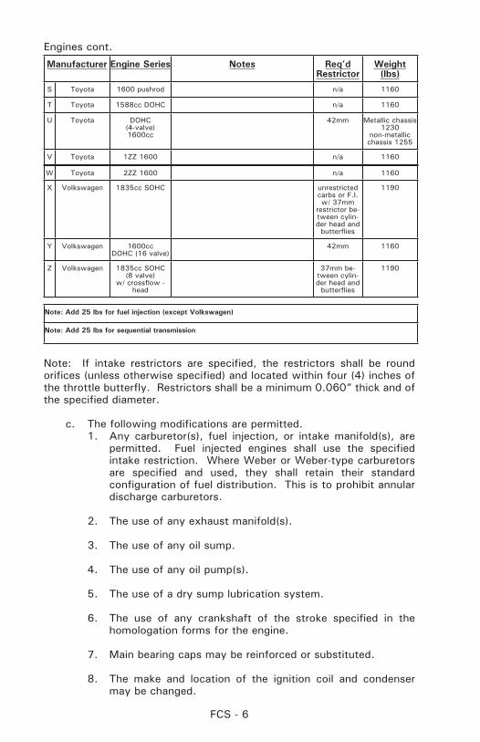
Engines cont.
Manufacturer Engine Series Notes Req’dRestrictor
Weight(lbs)
S Toyota 1600 pushrod n/a 1160
T Toyota 1588cc DOHC n/a 1160
U Toyota DOHC(4-valve)1600cc
42mm Metallic chassis 1230
non-metallic chassis 1255
V Toyota 1ZZ 1600 n/a 1160
W Toyota 2ZZ 1600 n/a 1160
X Volkswagen 1835cc SOHC unrestricted carbs or F.I. w/ 37mm
restrictor be-tween cylin-der head and
butterflies
1190
Y Volkswagen 1600ccDOHC (16 valve)
42mm 1160
Z Volkswagen 1835cc SOHC(8 valve)
w/ crossflow - head
37mm be-tween cylin-der head and
butterflies
1190
Note: Add 25 lbs for fuel injection (except Volkswagen)
Note: Add 25 lbs for sequential transmission
Note: If intake restrictors are specified, the restrictors shall be round orifices (unless otherwise specified) and located within four (4) inches of the throttle butterfly. Restrictors shall be a minimum 0.060” thick and of the specified diameter.
c. The following modifications are permitted.1. Any carburetor(s), fuel injection, or intake manifold(s), are
permitted. Fuel injected engines shall use the specified intake restriction. Where Weber or Weber-type carburetors are specified and used, they shall retain their standard configuration of fuel distribution. This is to prohibit annular discharge carburetors.
2. The use of any exhaust manifold(s).
3. The use of any oil sump.
4. The use of any oil pump(s).
5. The use of a dry sump lubrication system.
6. The use of any crankshaft of the stroke specified in the homologation forms for the engine.
7. Main bearing caps may be reinforced or substituted.
8. The make and location of the ignition coil and condenser may be changed.
FCS - 7
9. Any distributor and/or transistor ignition may be used provided it’s installation does not require any modification of the engine.
10. Any make or type of spark plug may be used.
11. The use of any starter is permitted provided it can be fitted without any modification to the engine.
12. Substitution of the clutch and flywheel is allowed provided there is no increase in clutch diameter. The use of dowel pins is permitted.
13. Any pistons and piston pins may be used.
14. Any camshaft(s) may be used.
15. Cam followers may be altered or substituted.
16. It is permitted to lighten, balance, or modify in shape by tooling the standard or optional components of the engine, provided it is always possible to identify them positively as such. It is not permitted to add any material to the components unless specifically authorized.
17. Engines may be rebored a maximum of 1.2mm (0.047 inches) over the standard size provided the resulting increase in total displacement does not exceed 1615cc.
18. The use of any alternate engine components considered replacement parts such as seals, bearings, valve guides, nuts, bolts, studs, washers, and gaskets is allowed, provided they are of the same type and dimension. Bushings may be added where none are fitted as standard, provided they are concentric and that the centerline of the bushed part is not changed. Water and oil passages may be restricted or plugged. The substitution of valve springs, valve spring retainers, and keepers is permitted. Any pushrods may be used.
19. Pulleys, including camshaft drive pulleys, may be altered or replaced with others of unrestricted origin. The use of any crankshaft vibration dampener is permitted.
20. The compression ratio may be increased by machining, using any head gasket(s), or eliminating of head gasket(s).
21. The installation of any engine vent or breather is permitted.
22. Generator or alternator is unrestricted.
23. The use of any rocker arms or rocker arm supports.
FCS - 8
24. Use of any connecting rod of the same basic material.
25. Valves are unrestricted in both size and material, provided the valve centerline is not altered.
26. Exhaust emission control air pumps, and associated lines and nozzles cannot be modified in any way except they may be completely removed. When these nozzles are removed from a cylinder head, the holes shall be completely plugged.
27. The use of any fuel pump(s) is permitted.
28. Valve or cam covers may be substituted.
29. Any external surface of the engine may be plated, painted, or anodized.
30. Engines produced with a cam carrier as a separate and distinct piece from the cylinder head or engine block may replace that cam carrier with a cam carrier of other manufacture, provided the replacement cam carrier affords no additional function other than the original cam carrier and provided the type and number of camshaft bearings remains the same.
31. The replacement of any jack shaft or idler shaft with another of the same basic material as the standard shaft is permitted, provided it performs no additional function over the original shaft.
A.3. Transmissiona. For all types of transmissions, no more than five forward speeds
and an operational reverse gear shall be used.
b. The use of an automatic gearbox is prohibited.
c. Electronic assisted gear change mechanisms and electronically controlled differentials are prohibited.
d. Gearboxes with shafts that are transverse to the longitudinal axis of the chassis are not allowed. The sole exception are the gearbox final drive (crownwheel) shaft axis and final drive shafts (half shafts). All change gears must be located in the case aft of the final drive.
FCS - 9
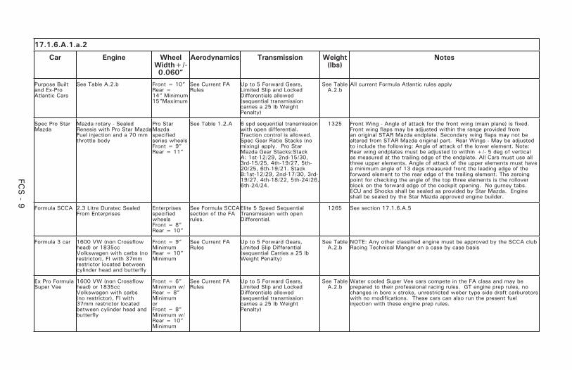
17.1.6.A.1.a.2
Car Engine Wheel Width+/- 0.060”
Aerodynamics Transmission Weight (lbs)
Notes
Purpose Built and Ex-Pro Atlantic Cars
See Table A.2.b Front = 10”Rear = 14” Minimum15”Maximum
See Current FA Rules
Up to 5 Forward Gears, Limited Slip and Locked Differentials allowed (sequential transmission carries a 25 lb Weight Penalty)
See Table A.2.b
All current Formula Atlantic rules apply
Spec Pro Star Mazda
Mazda rotary - Sealed Renesis with Pro Star Mazda Fuel injection and a 70 mm throttle body
Pro Star Mazda specified series wheelsFront = 9”Rear = 11”
See Table 1.2.A 6 spd sequential transmission with open differential. Traction control is allowed. Spec Gear Ratio Stacks (no mixing) apply. Pro Star Mazda Gear Stacks:Stack A: 1st-12/29, 2nd-15/30, 3rd-15/25, 4th-19/27, 5th-20/25, 6th-19/21. Stack B:1st-12/29, 2nd-17/30, 3rd-19/27, 4th-18/22, 5th-24/26, 6th-24/24.
1325 Front Wing - Angle of attack for the front wing (main plane) is fixed. Front wing flaps may be adjusted within the range provided from an original STAR Mazda endplate. Secondary wing flaps may not be altered from STAR Mazda original part. Rear Wings - May be adjusted to include the following: Angle of attack of the lower element. Note: Rear wing endplates must be adjusted to within +/- 5 deg of vertical as measured at the trailing edge of the endplate. All Cars must use all three upper elements. Angle of attack of the upper elements must have a minimum angle of 13 degs measured front the leading edge of the forward element to the rear edge of the trailing element. The zeroing point for checking the angle of the top three elements is the rollover block on the forward edge of the cockpit opening. No gurney tabs. ECU and Shocks shall be sealed as provided by Star Mazda. Engine shall be sealed by the Star Mazda approved engine builder.
Formula SCCA 2.3 Litre Duratec Sealed From Enterprises
Enterprises specified wheelsFront = 8”Rear = 10”
See Formula SCCA section of the FA rules.
Elite 5 Speed Sequential Transmission with open Differential.
1265 See section 17.1.6.A.5
Formula 3 car 1600 VW (non Crossflow head) or 1835cc Volkswagen with carbs (no restrictor), FI with 37mm restrictor located between cylinder head and butterfly
Front = 9” MinimumRear = 10” Minimum
See Current FA Rules
Up to 5 Forward Gears, Limited Slip Differential (sequential Carries a 25 lb Weight Penalty)
See Table A.2.b
NOTE: Any other classified engine must be approved by the SCCA club Racing Technical Manger on a case by case basis
Ex Pro Formula Super Vee
1600 VW (non Crossflow head) or 1835cc Volkswagen with carbs (no restrictor), FI with 37mm restrictor located between cylinder head and butterfly
Front = 6” Minimum w/Rear = 8” MinimumorFront = 8” Minimum w/Rear = 10” Minimum
See Current FA Rules
Up to 5 Forward Gears, Limited Slip and Locked Differentials allowed (sequential transmission carries a 25 lb Weight Penalty)
See Table A.2.b
Water cooled Super Vee cars compete in the FA class and may be prepared to their professional racing rules. GT engine prep rules, no changes in bore x stroke, unrestricted weber type side draft carburetors with no modifications. These cars can also run the present fuel injection with these engine prep rules.

FCS - 1
0
17.1.6.A.1.a.2 (cont.)
Car Engine Wheel Width+/- 0.060”
Aerodynamics Transmission Weight (lbs)
Notes
Pro Formula Ford 2000
2.0 Liter Zetec Front = 8”Rear = 10”
See Current FF2000 Zetec Championship Rules
4 Forward Gears, H-Pattern, with any combination of the following gears: 16/34, 15/30, 16/30, 17/30, 17/28, 18/28, 16/24, 19/27, 20/27, 19/24, 19/23, 24/28, 24/27, 24/26
1230 Must be prepared to current FF2000 Zetec Championship Rules, competitor must have current copy of the rules at all competitions.
PRO STAR MAZDA DIMENSIONS TABLE 1.A.2
DIMENSIONS (Refer to FF2000 drawing) Measurements Measurements
A. Maximum rear overhang from rear wheel axis 60 J. Maximum body width behind front wheels 132
B. Maximum front overhang from front wheel axis 100 K. Maximum nose width 129
C. Maximum height measured from the ground 94 @ rear wing L. Minimum cockpit opening 37
D. Exhaust height measured from the ground 34-44 M. Minimum cockpit parallel opening length 42
E. Maximum height of any aerodynamic Device 30 N. Minimum cockpit overall opening length 82
F. Minimum safety rollover bar height inline with driver’s spine 92 S. Maximum exhaust length from rear wheel axis 52
G. Minimum allowed helmet clearance 5 7. Minimum wheelbase 254
H. Maximum width 180 5. Minimum track 150
I. Maximum rear aerofoil width (includes endplates) 96
All above dimensions in cm.
FCS - 11
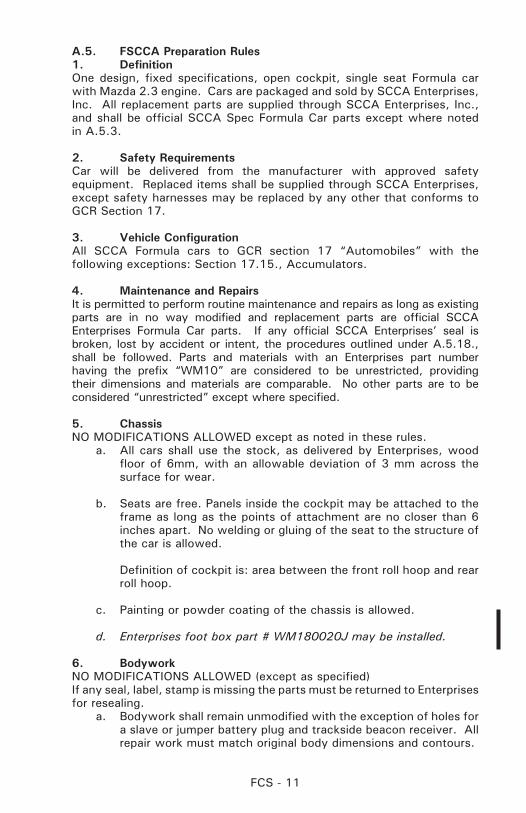
A.5. FSCCA Preparation Rules1. DefinitionOne design, fixed specifications, open cockpit, single seat Formula car with Mazda 2.3 engine. Cars are packaged and sold by SCCA Enterprises, Inc. All replacement parts are supplied through SCCA Enterprises, Inc., and shall be official SCCA Spec Formula Car parts except where noted in A.5.3.
2. Safety RequirementsCar will be delivered from the manufacturer with approved safety equipment. Replaced items shall be supplied through SCCA Enterprises, except safety harnesses may be replaced by any other that conforms to GCR Section 17.
3. Vehicle ConfigurationAll SCCA Formula cars to GCR section 17 “Automobiles” with the following exceptions: Section 17.15., Accumulators.
4. Maintenance and RepairsIt is permitted to perform routine maintenance and repairs as long as existing parts are in no way modified and replacement parts are official SCCA Enterprises Formula Car parts. If any official SCCA Enterprises’ seal is broken, lost by accident or intent, the procedures outlined under A.5.18., shall be followed. Parts and materials with an Enterprises part number having the prefix “WM10” are considered to be unrestricted, providing their dimensions and materials are comparable. No other parts are to be considered “unrestricted” except where specified.
5. ChassisNO MODIFICATIONS ALLOWED except as noted in these rules.
a. All cars shall use the stock, as delivered by Enterprises, wood floor of 6mm, with an allowable deviation of 3 mm across the surface for wear.
b. Seats are free. Panels inside the cockpit may be attached to the frame as long as the points of attachment are no closer than 6 inches apart. No welding or gluing of the seat to the structure of the car is allowed.
Definition of cockpit is: area between the front roll hoop and rear roll hoop.
c. Painting or powder coating of the chassis is allowed.
d. Enterprises foot box part # WM180020J may be installed.
6. BodyworkNO MODIFICATIONS ALLOWED (except as specified)If any seal, label, stamp is missing the parts must be returned to Enterprises for resealing.
a. Bodywork shall remain unmodified with the exception of holes for a slave or jumper battery plug and trackside beacon receiver. All repair work must match original body dimensions and contours.
FCS - 12
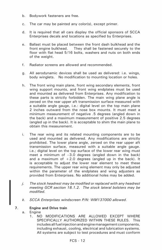
b. Bodywork fasteners are free.
c. The car may be painted any color(s), except primer.
d. It is required that all cars display the official sponsors of SCCA Enterprises decals and locations as specified by Enterprises.
e. Ballast must be placed between the front dash bulkhead and the front engine bulkhead. They shall be fastened securely to the floor with flat head 5/16 bolts, washers and nuts on both ends of the weight.
f. Radiator screens are allowed and recommended.
g. All aerodynamic devices shall be used as delivered: i.e. wings, body winglets. No modification to mounting location or holes.
h. The front wing main plane, front wing secondary elements, front wing support mounts, and front wing endplates must be used and mounted as delivered from Enterprises. Any modification to these parts is strictly forbidden. The main wing plane angle is zeroed on the rear upper aft transmission surface measured with a suitable angle gauge, i.e.: digital level on the top main plane 2 inches outward from the nose box mounts. It must meet a minimum measurement of negative .5 degrees (angled down in the back) and a maximum measurement of positive 2.5 degrees (angled up in the back). It is acceptable to shim the main plane to obtain this measurement.
i. The rear wing and its related mounting components are to be used and mounted as delivered. Any modifications are strictly prohibited. The lower plane angle, zeroed on the rear upper aft transmission surface, measured with a suitable angle gauge. i.e.; digital level on the top surface of the lower rear wing must meet a minimum of –3.0 degrees (angled down in the back) and a maximum of +2.0 degrees (angled up in the back). It is acceptable to adjust the lower rear element to meet these requirements. The upper rear wing element may only be adjusted within the parameter of the endplates and wing adjusters as provided from Enterprises. No additional holes may be added.
j. The stock headrest may be modified or replaced with any headrest meeting GCR section 18.1.2. The stock lateral bolsters may be modified.
k. SCCA Enterprises windscreen P/N: WM137000 allowed.
7. Engine and Drive traina. Engine
1. NO MODIFICATIONS ARE ALLOWED EXCEPT WHERE SPECIFICALLY AUTHORIZED WITHIN THESE RULES. This includes all fuel injection and engine management components, including exhaust, cooling, electrical and lubrication systems. All systems are subject to test procedures and must conform
FCS - 13
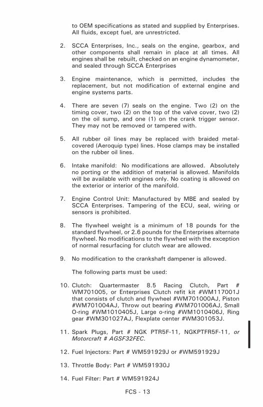
to OEM specifications as stated and supplied by Enterprises. All fluids, except fuel, are unrestricted.
2. SCCA Enterprises, Inc., seals on the engine, gearbox, and other components shall remain in place at all times. All engines shall be rebuilt, checked on an engine dynamometer, and sealed through SCCA Enterprises
3. Engine maintenance, which is permitted, includes the replacement, but not modification of external engine and engine systems parts.
4. There are seven (7) seals on the engine. Two (2) on the timing cover, two (2) on the top of the valve cover, two (2) on the oil sump, and one (1) on the crank trigger sensor. They may not be removed or tampered with.
5. All rubber oil lines may be replaced with braided metal-covered (Aeroquip type) lines. Hose clamps may be installed on the rubber oil lines.
6. Intake manifold: No modifications are allowed. Absolutely no porting or the addition of material is allowed. Manifolds will be available with engines only. No coating is allowed on the exterior or interior of the manifold.
7. Engine Control Unit: Manufactured by MBE and sealed by SCCA Enterprises. Tampering of the ECU, seal, wiring or sensors is prohibited.
8. The flywheel weight is a minimum of 18 pounds for the standard flywheel, or 2.6 pounds for the Enterprises alternate flywheel. No modifications to the flywheel with the exception of normal resurfacing for clutch wear are allowed.
9. No modification to the crankshaft dampener is allowed.
The following parts must be used:
10. Clutch: Quartermaster 8.5 Racing Clutch, Part # WM701005, or Enterprises Clutch refit kit #WM117001J that consists of clutch and flywheel #WM701000AJ, Piston #WM701004AJ, Throw out bearing #WM701006AJ, Small O-ring #WM1010405J, Large o-ring #WM1010406J, Ring gear #WM301027AJ, Flexplate center #WM301053J.
11. Spark Plugs, Part # NGK PTR5F-11, NGKPTFR5F-11, or Motorcraft # AGSF32FEC.
12. Fuel Injectors: Part # WM591929J or #WM591929J
13. Throttle Body: Part # WM591930J
14. Fuel Filter: Part # WM591924J

FCS - 14
15. Air Filter: Part # WM301020
16. Exhaust systems may be thermal coated or wrapped.
17. A heat shield between the engine block and the exhaust system is recommended for the purpose of protecting hoses, shifter cable, and wiring from the heat of the exhaust.
18. An SCCA Enterprises muffler kit part # WM301046J is required to meet sound requirements. The muffler may not extend beyond the back of the transmission. An additional muffler may be added to accompany the stock muffler as needed to meet sound requirements.
19. An optional air to oil cooler is allowed on the scavenge return to the oil tank. The maximum core size is 13 inches wide by 6.5 inches high. No water to oil heat exchanger is allowed.
20. An optional SCCA Enterprise alternator kit is allowed, Part # WM1100101J
21. Fuel shall meet the requirements for IT cars per GCR section 17.4.1.
22. Fuel pump and injector upgrade #WM1159101J consisting of pump # WM591901J and injectors # MN591929J allowed.
b. Transmission1. The Elite design and developed EVD 5 speed sequential
transaxle is the only permitted gearbox. The casting has to remain original. No internal or external modification (including lightening) other than normal racing repair.
2. The servicing, replacement and modification of internal components is permitted by the competitor. With the following exceptions:
a. All components must be ferrous metal, except for bearing retainers and bearing cages.
b. Components manufactured by alternate manufacturers are per mitted. Replacement com ponents must be direct replacements to the original components. Absolute minimum weights are listed below.
3. The rear cover plate may manufactured or remanufactured using aluminum.
4. Only the following gear ratios are permitted:1st gear combination 12:29 Ratio number 2.412nd gear combination 15:28 1.863rd gear combination 16:24 1.50
FCS - 15
4th gear combination 18:22 1.225th gear combination 24:26 1.08
5. Differential – Only final drive ratio allowed is 2.75. The differential must remain an open differential. No limited slip mechanism is allowed. Differential must work as supplied from Elite (no tightening of the differential to limit slip) Must be able to use existing components from Elite.
6. Polishing, shot peening, REM© Isotropic treatment, heat and cold treatments are allowed. No coatings or plating is allowed.
7. Shift cable is free, but shifting must remain cable operated.
8. The shift actuator assembly must operate as supplied by enterprises. It can be polished, shot peened, or have REM treatment, heat and cold treatments.
MINIMUM WEIGHTS OF THE FOLLOWING PARTS Differential Housing (both parts including bearings) 7.4 lbsRing Gear 3.6 lbsPinion Shaft 4.0 lbs1st gear 2.7 lbs2nd gear 1.2 lbs3rd gear 1.1 lbs4th gear 1.1 lbs5th gear 1.0 lbs
8. Suspensiona. NO MODIFICATIONS ALLOWED. Adjustments are permitted
within the limits of the suspension and steering components. All rod ends shall be engaged at least 1.5 times the diameter of the end.
b. Front Springs: 600 lbs. ±25 lbs. Part # WM203008. Wire size shall measure .360” ±.005”.
Rear Springs: 1000 lbs. ±25 lbs. Part # WM203009. Wire size shall measure .410” ± .005”.
c. Competitors may use the entire travel of all suspension adjusted components as delivered. Alternate parts are not allowed.
d. All suspension parts shall have the SCCA code embedded (a label/or an Enterprises stamp) in the part. If they do not it is required to return part to Enterprises for proper labeling.
e. Rod ends may be replaced with rod ends having specifications equal to or greater than the OEM supplied rod ends. This includes dimensional material and strength specifications. Replacement rod ends shall be capable of being installed with no modifications to any original components.
FCS - 16
f. Anti-roll bars (sway bars) may be disconnected, but not removed.
1. Anti roll bar sizes: Front .875” OD ±.005” Top Tee .750” x .135” wall, ±.005” Top Tee Length: 7.5” maximum end to end Rear lower stalk .615” Dia. ±.005” Upper stalk .765” ±.005” Arm length 5.470” shoulder to shoulder
9. Shocks a. NO MODIFICATIONS ALLOWED. 4 Bilstein Shocks are the only
permitted shocks allowed, Part # WM203001
b. No bump rubbers, packers or shims are allowed
c. The only adjustment will be at the spring perch.
d. All shock absorbers must be sealed by SCCA Enterprises.
10. Steering:NO MODIFICATIONS ALLOWED, except as described within these rules
a. An alternate steering wheel may be used. “Butterfly” style steering wheels are not allowed.
b. Upper steering shaft may be modified to accept an alternate steering wheel and/or hub (if applicable). It may also be modified to accommodate a larger driver.
11. Brakes:NO MODIFICATIONS ALLOWED, except as described within these rules. Only the AP 4 PISTON CALIPER BRAKE SYSTEM AS SUPPLIED WITH VENTED AP ROTORS shall be used
a. Brake pads as supplied from SCCA Enterprises, SBS, Part # WM801001
b. Brake rotors are used as delivered, no drilling or lightening is allowed. Minimum Diameter is 10.450”. Part # WM801002 Left, Part # WM801003 Right. Min width is .600”, Min Weight: 5lbs 4 oz
c. Master cylinders must be the Girling integral reservoir type.
Front master cylinder is.700” piston diameter, Part # WM802005
Rear master cylinder is .750” piston diameter, Part # WM802006
d. Calipers must be AP 4 piston. Part numbers are: LF # WM802004 RF #WM802003 LR # WM802002 RR # WM802001
FCS - 17
e. Brake lines are free (no plastic allowed) .
12. Wheels (Only wheels supplied by SCCA Enterprises)NO MODIFICATIONS or MACHINING ALLOWED Aluminum racing wheel supplied from SCCA Enterprises with SCCA logo. If logo is worn off, wheels must be returned to Enterprises.
Front: 8 in X 13 in Part # WM 205001 Rear: 10 in X 13 in Part # WM205002
a. All wheel bearings shall be run with grease (not oil), no special coatings are allowed, and the bearing grease seal shall be intact. No ceramic wheel bearings are permitted
b. Wheel spacers are not allowed.
13. TiresTires must run in sets of 4 as stated below:
Hoosier R 45 Compound Front: 21.5 in X 8.0 in X13.0in Rear: 22.0 in X10.0 in X 13.0 in
Front: 21.5 in 7.5 in X 13.0 in Rear: 22.0 in 9.0 in X13.0 in
a. A competitor shall start the race on the same set of tires (meaning the original four) as used in a qualifying session for the race. The only exception is rain tires. It is the responsibility of the competitor to ensure their tires are marked appropriately for qualifying and race sessions. It is recommended that regions offer these services at a central location such as pre-grid or TECH.
b. A change of tires during or between a qualifying and race session shall automatically result in all previous times being disallowed.
c. If a tire is damaged during a qualifying session the competitor may replace that tire with a used tire upon approval of the Chief Steward. Should a tire be replaced for any reason, the competitor shall forfeit his grid position and start at the back of the grid.
14. Electrical System: NO MODIFICATIONS ALLOWED, except as described within these rules.
a. Wiring harnesses must remain as delivered.
b. Battery may be replaced with a larger one as long it remains in the same location.
c. Battery wiring is free. Car must shut off when master switch is turned off.
d. Any instrumentation is allowed.
e. Data acquisition is allowed, no telemetry is allowed.
FCS - 18
f. At any time during an SCCA sanctioned event it is possible that technical scrutineering personnel can randomly remove and replace ECU modules or other components with other competitor’s components or components, which the technical or scrutineering personnel will provide.
15. WeightThe car shall weigh 1265 lbs. minimum, including the driver.
16. UpdatesProvisions will be made for updates on all safety and mechanical improvements. Such updates will be effective when authorized by SCCA Enterprises, announced by the National Office, and published in SportsCar.
17. Vehicle LogbookThe Vehicle Logbook for each SCCA Formula Car remains the property of SCCA Enterprises and will contain not only the record of technical inspections, but also the major maintenance performed and all transfers of ownership. The Vehicle Logbook number will be the same as the factory chassis number that is stamped on the name plate mounted on the fuel cell behind the driver’s shoulders. When the vehicle is sold, traded, or scrapped, the logbook shall be sent to SCCA Enterprises, Inc.,. 14550 E. Easter Ave Suite 400 Centennial, Co. 80112. The logbook will them be reissued to the new owner. When the logbook has been filled, a new one shall be requested from SCCA Enterprises, Inc.
A FEE OF $200 WILL BE CHARGED FOR LOST LOGBOOKS.
The logbook shall be presented at scrutineering for each event entered. All SCCA Formula Cars are subject to normal safety inspection. Additionally, scrutineers will check each official seal. A competitor may not be barred from competing at a specific event if a seal is broken, damaged, lost or part not properly labeled but the part may be considered suspect and will be treated as such and will be required to be sent back to Enterprises for inspection. If engine cam cover or oil pan seals are broken, damaged, or missing, the engine shall be removed and sent to SCCA Enterprises for testing and resealing. The competitor will bear all expenses at the competitor’s cost prior to the next event.
18. Seals SCCA Enterprises engine seals are required for all races. Any competitor who runs an event without all proper engine seals in the required locations shall have his engine removed and shipped to SCCA Enterprises for testing and sealing after that event. The competitor will be responsible for all cost incurred by this procedure regardless of the findings, and subject to penalty by the SOM if engine is found to be not as specified.
SCCA Enterprises, Inc., seals are required on all Formula Car Engines.
Any counterfeit engine seal found by an authorized representative of SCCA, Inc., or SCCA Enterprises, Inc., shall immediately render that engine illegal for further use, without need of dyno testing or inspection. SCCA Enterprises, Inc., will not be under any obligation to bring an illegally
FCS - 19
sealed engine back to legal condition. Penalties shall include all of the following: 19.a., 19.b., 19.c., and 19.d.
19. Penalties (Specific to SCCA Sports Racer)If a competitor refuses to give his engine and/or unlabeled parts for testing per a request of the Chief Steward (GCR 6.11.), the following penalties will automatically be imposed:
a. Vehicle logbook will be impounded.
b. Disqualification from the event.
c. Suspension of SCCA competition privileges for thirty (30) days.
d. The car and drive train are suspended from competition until the unit(s) specified by the Chief Steward are replaced.
In a case where a competitor does comply with the Chief Steward’s request to have an engine and/or parts inspected and the impounded unit(s) are found legal, the SCCA, will stand all the costs incurred for the testing, including shipping. Should the impounded unit(s) be found illegal, the following penalties will be imposed:
1. Disqualification from the event.
2. A fine of $250.00
3. $500.00 testing fee plus freight charges paid to Enterprises
4. Competition privileges will be suspended immediately, and the suspension will continue for a minimum of thirty (30) days after the date when all fines and costs are paid in full and the license is received by the Chairman SOM or the SCCA Topeka Office.
5. For a second illegal drive train offense, the competitor will be permanently disqualified from further SCCA Formula Car competition.
20. SCCA Formula Car Drive Train Protesta. Protests shall be filed per the GCR.
b. Protestor will specify the drive train item suspected (i.e., transmission or engine). The teardown bond to remove the motor and transmission is in three (3) parts:
1. Remove and replace motor and transmission - $400.00
2. Ship motor to Enterprises and test - $500.00 plus freight and crating charges
3. Protest Fee: Regional - $25.00, National - $50.00 Item 1 will be done by an SCCA representative or other shop that is
FCS - 20
equipped for this type of work and will be paid directly.
c. SCCA Enterprises will inspect the motor, (item 2), and will notify the Chairman SOM as soon as possible as to the results.
d. Enterprises shall retain the evidence, and the SCCA shall retain the fee, (item 3), until the period for appeal has passed.
e. The Chairman SOM is required to inform SCCA Enterprises of the protest using the FSCCA Protest Information Form. A copy of the protest shall be sent to Enterprises.
If the protest proves to be valid and any appeal fails, the protest fee, (item 3), will be returned to the protestor. Also, the protestee will be required to reimburse the protestor the remaining fees ($900). The protestee will not be allowed to compete again until all costs are paid. If found legal, the protester forfeits fee (items 1 and 2) above.
f. If found illegal, competition privileges will be suspended immediately, and the suspension will continue for thirty (30) days after all costs are paid in full.
g. For a second illegal drive train offense, the competitor will be permanently disqualified from competing in FSCCA competition.
21. Accessory Itemsa. Mirrors are free.
b. Two-way radios may be installed in the car. All components shall be securely attached and approved by Tech inspection.
c. Racers tape may be used to repair crash damage, or as a precautionary means of securing the body retaining latches. Crash-damage is defined as having occurred during the current event, and the tape should be of an appropriate color if possible. Taping of body joints is not allowed
d. The spark plug wires may be fire sleeved and may be loomed, but must be original Mazda wire as supplied by Enterprises.
e. Engine compartment fluid hoses may be insulated using heat shield or wrap.
f. Front and rear tow hooks are required, see GCR section 17.31.
B. FORMULA CONTINENTAL PREPARATION RULEFormula Continental is a Restricted class. Therefore, any allowable modifications, changes, or additions are as stated herein. There are no exceptions. IF IN DOUBT, DON’T. Homologation is required for all cars registered after January 1, 1983.
B.4. FORMULA 2000, CLASSED IN FORMULA CONTINENTALDescription: Single seater racing cars as defined by these regulations.
FCS - 21
All newly constructed cars shall meet the 1986 construction rules for Formula F cars.
a. Safety:Must comply to GCR Sections 17., 18., 19., and 20..
b. Chassis:The chassis shall be of tubular steel construction with no stress-bearing panels except bulkhead and undertray; curvature of the undertray shall not exceed 2.54cm (1 inch). Monocoque chassis construction is prohibited. Stress bearing panels are defined as: sheet metal affixed to the frame by welding, bonding, rivets, bolts, or screws which have centers closer than 15.24cm (6 inches). Body panels cannot be utilized as stress bearing panels, except as required for 1986 construction rules. The use of composite materials using carbon and/or Kevlar reinforcement is prohibited.
No engine oil or water tubes are permitted within the cockpit.
It is not permitted to construct any suspension member in the form of an airfoil or to incorporate a spoiler in the construction of any suspension member.
c. Bodywork and Airfoils:See table of dimensions. (Airfoils are a requirement for this class.)
The use of composite materials using carbon reinforcement is prohibited, except as permitted herein.
Ground effects are prohibited. Deviation of the undertray may not exceed 2.54cm (1”) in the area between the rearmost point of the front tire to the frontmost point of the rear tire. Diffuser undertrays are permitted.
Cockpit: Forward-facing roll bar/roll cage bracing and required padding will not be considered in the dimensions shown in the table.
d. EnginesThe only permitted engines are:The Ford 2 liter single overhead camshaft “NE” series engine or the 1971-74 Pinto/Capri 2 liter single overhead camshaft engine.
The Ford Zetec ZX3 2 liter dual overhead camshaft engine (see section e.)
The Ford 2 liter single overhead camshaft “NE” series engine and the 1971-74 Pinto/Capri 2 liter single overhead camshaft engine shall conform to the following specifications. The nominal bore is 90.84mm and the nominal stroke is 76.95mm (Note: All
FCS - 22
blocks shall contain casting number HM6015BA, HM6015AA or HM6015BB. Dashes in the casting number are not relevant.). Production tolerances are permitted providing the total swept volume does not exceed 2000cc.
1. The rockers shall remain entirely unmodified. Alternate manufacturers may be used as long as the original materials and dimensions are the same. Camshafts must be from Ford Motor Company, or Crower part # E-57553 FF2000, or from the approved supplier. Camshaft geometry shall be stock. Offset keys are permitted. Tuftriding or Parkerizing is permitted. Maximum valve lift at determined points by camshaft rotation will be established. The use of a low rate substitute valve spring is permitted. Load characteristics of special checking spring: twelve (12) lbs., at 1.417 inches, thirty (30) lbs., at 1.000 inches. Maximum valve lift against cam angle with zero tappet clearance: 0.400 +/- 0.005 An adjustable camshaft sprocket which retains the same number of teeth and pitch as the stock sprocket may be used.
2. A standard crankshaft shall be used. Spot machining to achieve balance is permitted. Tuftriding, Parkerizing, shot peening, shot blasting, and polishing are permitted. Minimum weight: twenty-seven point five (27.5) lbs.
3. The flywheel shall be a standard component or the approved alternate Elite-001. The minimum weight is 14.4 lbs. with ring gear. The flywheel may be machined to achieve minimum weight. Spot machining to achieve balance is permitted. Flywheel bolts are free and locating dowels are permitted. A 1600 GT starter ring may be fitted. The use of any single plate clutch is permitted provided no modification is made to the flywheel other than changing the points of attachment of the clutch to the flywheel. Carbon fiber clutches are not permitted.
4. Maximum compression ratio will be controlled as follows:
A. Minimum Cylinder Head combustion chamber volume 49cc (not including head gasket). Polishing and/or tooling of the cylinder head to achieve only the required combustion chamber volume is permitted.
B. Standard Ford gasket or Ferrea part number G50100 may be used. Gaskets will have a minimum thickness of 0.9mm, minimum diameter of cylinder aperture of 92mm.
C. Pistons shall not protrude above cylinder block surface at TDC.
5. It is permissible to reshape inlet and exhaust port by removal of metal within limits. Addition of material in any form is prohibited. Maximum diameter of inlet port at manifold

FCS - 23
head face 39.5mm. Maximum dimensions of exhaust port at manifold face 35.5mm x 27mm. The distance between the valve centers and the angles of the valves shall not be altered.
6. Pistons shall be standard Ford Mahle, AE Hepolite, or J&E. Pistons must be unmodified in any way except for balancing and as detailed herein.
The following combinations are permitted:
A. Mahle piston P/N 80HM6102LA with rings, pin, connecting rod (with bolts), but without bearings:Minimum permitted weight = 1332.5 grams.
B. Mahle piston P/N 85HM6102DA with rings, pin, connecting rod (with bolts), but without bearings: Minimum permitted weight = 1255 grams.
NOTE: This piston may have either casting #90V108 or #90V118.
C. AE Hepolite piston P/N 21426, casting P/N 21426 (AE Hepolite) with rings, pin, connecting rod (with bolts), but without bearings: Minimum permitted weight = 1255 grams.
D. JE piston P/N M-6102-B200 with rings, pin, connecting rod (with bolts), but without bearings: Minimum permitted weight = 1255 grams.
NOTE: M-6102-B200 piston assembly is now made by JE and is visually different. I.D. Marks: M-6102-B200, Ford racing logo. All marks pin stamped on wrist pin bosses.
All three (3) piston rings shall be fitted, compression rings and scraper (second) shall be one piece, single homogeneous material-type with conventional plain gaps. Chromium plating of the top ring is optional; oil control rings shall be either single piece twin-land type or apex three piece (two rails and an expander).
Localized machining of the gudgeon pin bosses to achieve balance and weight by simple machining; all external surfaces, dimensions, and profiles shall remain standard with the exception of the top surface of the piston crown which may have simple machining to achieve balance, and as required in Section 17.1.5.B.5.d.3.
7. Valves may be of Ford manufacture or Ferrea part numbers VSOIN200 and VSOEX2000. Valves shall remain standard; no reprofiling or polishing is permitted.
The original forty-five (45) degree seat angle shall be
FCS - 24
maintained.
Maximum face diameter inlet 42.2mm. Maximum face diameter exhaust 36.2mm. Maximum valve stem diameter 8.4mm.
8. Full connectng rods may be standard Ford, Cosworth, Oliver, or Crower. The approved Crower part numbers are SP93230B-4 or SP93230PF-4. Any rod bolts may be used. Floating piston pins may be used. Standard rod length must be 5.00 inches (+.005” -.010”). Machining is permitted to remove metal from the balancing bosses to achieve balance only. Tuftriding, Parkerizing, shot peening, shot blasting, polishing, etc., are permitted.
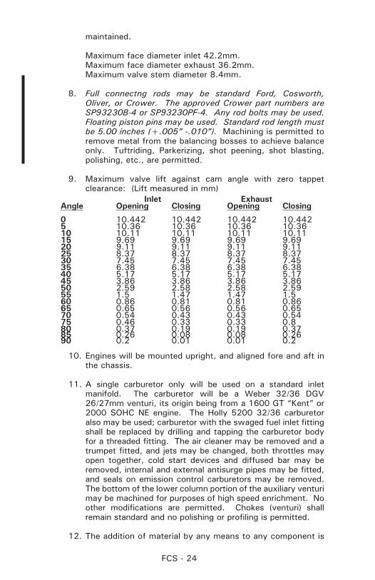
9. Maximum valve lift against cam angle with zero tappet clearance: (Lift measured in mm)
Inlet ExhaustAngle Opening Closing Opening Closing
0 10.442 10.442 10.442 10.4425 10.36 10.36 10.36 10.3610 10.11 10.11 10.11 10.1115 9.69 9.69 9.69 9.6920 9.11 9.11 9.11 9.1125 8.37 8.37 8.37 8.3730 7.45 7.45 7.45 7.4535 6.38 6.38 6.38 6.3840 5.17 5.17 5.17 5.1745 3.86 3.86 3.86 3.8650 2.59 2.58 2.58 2.5955 1.5 1.47 1.47 1.560 0.86 0.81 0.81 0.8665 0.65 0.56 0.56 0.6570 0.54 0.43 0.43 0.5475 0.46 0.33 0.33 0.880 0.37 0.19 0.19 0.3785 0.26 0.08 0.08 0.2690 0.2 0.01 0.01 0.2
10. Engines will be mounted upright, and aligned fore and aft in the chassis.
11. A single carburetor only will be used on a standard inlet manifold. The carburetor will be a Weber 32/36 DGV 26/27mm venturi, its origin being from a 1600 GT “Kent” or 2000 SOHC NE engine. The Holly 5200 32/36 carburetor also may be used; carburetor with the swaged fuel inlet fitting shall be replaced by drilling and tapping the carburetor body for a threaded fitting. The air cleaner may be removed and a trumpet fitted, and jets may be changed, both throttles may open together, cold start devices and diffused bar may be removed, internal and external antisurge pipes may be fitted, and seals on emission control carburetors may be removed. The bottom of the lower column portion of the auxiliary venturi may be machined for purposes of high speed enrichment. No other modifications are permitted. Chokes (venturi) shall remain standard and no polishing or profiling is permitted.
12. The addition of material by any means to any component is
FCS - 25
prohibited.
13. It is permitted, as a means of repair, to replace damaged valve seats and cylinder bores by replacement cast iron valve seat inserts and cast iron cylinder liners; valve guides may be replaced with cast iron or bronze, all to standard dimensions. Repairs to the cam towers to facilitate replacement of cam bearing and/or replacements of broken or cracked towers is permitted as long as the cam bearing center line is not changed and that one original cam tower is retained. Line boring of cam bearing caps is permitted.
14. Balancing of reciprocating and rotating parts is permitted only by removal of metal from locations so provided by the manufacturer.
15. Non-standard rocker covers are permitted providing they in no way improve the performance of the engine.
16. Standard valve spring retainers shall be used, and single valve springs only are permitted. Shims are permitted, and valve springs are otherwise free.
17. Exhaust system and manifold are unrestricted, within SCCA safety regulations.
18. Lubrication system is unrestricted; dry sump is permitted. Localized machining of the cylinder block is permitted to allow fitting of the oil pump.
19. Oil coolers are unrestricted.
20. A liquid cooling system is mandatory, but radiator and water pump are unrestricted. The radiator, if housed in or incorporating a cowl air-scoop deflector, shall comply with body regulations.
21. Fuel Pump: Unrestricted.
22. Distributors are unrestricted providing they retain the original drive and location. The distributor is defined as the component which triggers the L.T. current and distributes the H.T. current. The Ignition Timing may only be varied by vacuum and/or mechanical means. It is prohibited to use any other method or component to trigger, distribute, or time the ignition.
23. Only the standard inlet manifold shall be used.
The ports may be reshaped by the removal of metal as long as the following dimensions are maintained: maximum size at head face = 1.437” (36.5mm), maximum size at carburetor flange = 3.405” (86.5mm) x 1.595” (40.5mm). The carburetor seat face may be machined to horizontal

FCS - 26
in the fore to aft plane. The diameter of the ports may exceed the above listed dimensions if the casting bore is untouched and in its original state. The water passages in the inlet manifold may be plugged. Holes in the inlet manifold resulting from the removal of emission/vacuum lines shall be plugged.
24. Gaskets and seals are unrestricted except for the cylinder head gasket that has the requirements listed in B.4.d.4.B. and the intake gasket. The intake gasket thickness must not exceed 1.1mm. Intake gasket is not to be construed as a spacer.
25. Pump, fan, and generator drive pulleys are unrestricted.
26. The crankcase breather may be altered or removed, but all breathers shall discharge into a catch tank.
27. Mechanical tachometer drives may be fitted.
28. Generators are optional.
29. Standard oversize and undersize bearings are permitted. This does not allow reducing the bearing surface area by reducing the width of standard bearings.
30. The use of non-standard replacement fasteners (nuts, bolts, screws, studs, and washers) which are not connected with or which do not support the intake manifold or any moving parts of the engine is permitted.
31. Only modifications or additions specifically covered by these regulations are permitted. All engine components not covered by these regulations shall remain completely standard and unmodified.
e. Engines - Zetec The Ford Zetec ZX3 engine shall conform to the following
specifications and may be modified only as specifically allowed. If these specifications do not explicitly allow a modification, then it may not be done. The philosophy of the Zetec engine in FC is to allow limited engine rebuilds but no performance modifications to the engine. Blue printing, balancing, head porting, polishing, etc. are strictly prohibited and against the spirit of the Zetec formula. Where Ford part numbers are specified, normal industry part number supersession is expected and the superseding part numbers are automatically included.
1. The cylinder head may not be ported, polished, or machined. A standard three-angle “production” valve job is required and the only allowed angles are those defined in the Ford factory manual. The intake valve seats must be 30° 45° 70° with the 45° face a minimum 1.5 mm wide. The exhaust valve seats must be 30° 45° 55° with the 45° seat 1.5 mm
FCS - 27
wide minimum. The camshaft, valves, springs, and shim/bucket components must be original Ford parts and may not be modified in any way. Only original unmodified Ford parts may be used for direct replacement. The camshafts must remain as ground by Ford; no polishing is permitted. Valve seats may not be replaced. The head may not be surfaced or milled beyond the minimum thickness of 5.230” measured between the cam cover seating surface and the lower plane of the head. Only the Ford #RFYS4E6090AC head is allowed. The only allowed camshafts are the Ford #L913B YSAA intake and #L913B C2B exhaust. The original, unmodified Ford camshaft and crankshaft timing pulleys must be used. Camshaft timing is unrestricted.
2. Pistons, crankshaft, and rods may be replaced only with standard original Ford replacement parts. The crankshaft may not be ground or polished in any way and must have stock dimensioned main and rod bearing journals. The rod journals must remain stock and the rods may not be bored or remanufactured in any way. The rod and crankshaft bearings may be replaced only with original sized Ford bearings. Oversize bearings are not permitted. The required crankshaft main bearing journal dimension is 2.282-2.283 inches and the required crankshaft rod journal dimension is 1.846-1.847 inches. The crankshaft centerline to deck dimension is 8.378 inches and may not be altered. The main bearing housing bore is 2.452-2.453 inches and the rod housing bore is 1.9642-1.9650 inches. Only original Ford rod bolts with a minimum weight of 24.6 grams or ARP rod bolts with a minimum weight of 23.5 grams may be used.
3. Only original stock Ford replacement piston rings may be used. The ring end gaps may not be altered and must remain as manufactured by Ford. All of the rings must be installed including the complete oil scraper assembly. The piston bore may be honed solely to allow piston ring seating. The first and second compression rings must be installed in the positions designated by Ford.
4. All surfaces on the head, block, rods, pistons, and crankshaft must remain as manufactured by Ford and may not be altered in any way. The original casting marks and cast surfaces must remain as-cast and also meet all of the Ford design values and tolerances as stated in the Ford factory manual or as delineated in these specifications. The block may not be decked. Only Ford Zetec ZX3 blocks with block numbers #RFYS4G6015AA or #RFYS4G6015AD are permitted. The required compression ratio is 9.6:1, the required standard bore is 3.3390 – 3.3410 inches and the required stroke is 3.461 inches. The maximum bore dimension of 3.3410 inch is intended to allow for cylinder wear only. It is not permitted to machine to this dimension. This measurement will be taken .250 below the block deck where the bore is untouched by the piston ring.
FCS - 28
5. Flywheel: The minimum weight is 8.0 lbs. and any weight removal from the specified flywheel must come from the clutch plate surface. Only the Quarter Master #QM107160 flywheel may be used.
6. Any 7¼ inch single plate or double plate, non-carbon fiber clutch is allowed.
7. Any oil pan is allowed. The oil pan may not contain an oil scraper between the oil pan and the block. No device in the oil pan may be contoured to the crankshaft assembly to function as an oil scraper nor may any device be closer to the rotating crankshaft assembly than 0.5 inches.
8. Any three-stage oil pump with a maximum of two scavenge stages is allowed. The maximum scavenge rotor dimensions are 1.375 inches in diameter and 1.600 inches in length. The minimum pressure rotor dimensions are 0.863 inches in diameter and 1.600 inches in length.
9. The exhaust system manifold tubing OD must be 1.5 inches and the manifold tubes must be a minimum of 24 inches in length and must terminate into a single exhaust pipe through a 4 into 1 collector. The collector angles must be the standard 15 degree bend, (30 degree included angle) with an exit diameter of 2 inches. The tail pipe must be a minimum of 24 inches in length. 4 into 2 into 1 exhaust collectors or reduced diameter venturi sections are prohibited.
10. ECU: The Pectel T2 unit is required. The current specification “SCCA Club” map is required. Failure to use the current “SCCA Club” map will result in an automatic penalty of 1 year suspension from SCCA club racing. The map is available at the SCCA web site.
11. Intake manifold and fuel injection components: The Quicksilver RacEngines (QSRE) intake manifold, throttle bodies, air horns, fuel rail and injector system are required and must be used with no modifications of any kind. The only allowed intake manifold and throttle body combination is the #0138 manifold available through QSRE. Only stock Ford fuel injectors may be used and they may not be modified in any way. Fuel injectors may be replaced only with stock Ford injector part number #0280155887 XS4U-AA.
12. Intake restrictor: The QSRE #1975 intake restrictor must be used. It must not be modified in any way. The restrictor internal diameter is 1.275 inches and this value cannot be exceeded in any measurement of the diameter. The restrictor port centerlines or shape may not be altered.
13. Engines will be mounted and aligned fore and aft in the chassis
FCS - 29
14. The addition of material by any means to any component is prohibited
15. Non-standard rocker covers are permitted providing they in no way improve the performance of the engine.
16. Oil coolers are unrestricted.
17. A liquid cooling system is mandatory, but radiator and water pump are unrestricted.
18. Fuel pump is unrestricted.
19. Gaskets and seals are unrestricted except for a. cylinder head gasket, Ford part number XS7Z6051CA
b. a continuous o-ring of cross-section of 0.100 inches must be fitted to each intake runner groove between the intake manifold and the head which to ensures that no air by-passes the o-ring seal
20. Pump, fan, and generator drive pulleys are unrestricted.
21. The use of non-standard replacement fasteners (nuts, bolts, screws, studs, and washers) which are not connected with or which do not support the intake manifold or any moving parts of the engine are permitted.
f. Suspension:All parts shall be of steel or ferrous material, with the exception of hubs, hub adapters, hub carriers, bell cranks, pivot blocks, bearings and bushes, spring caps, abutment nuts, anti-roll bar links, shock absorber caps, and nuts. Titanium is prohibited.
Springs: Steel only.
Shock Absorbers: Steel or aluminum alloy body.
g. Brakes: Unrestricted (with the below restrictions)Brake rotors and calipers must be ferrous.
h. Steering: Unrestricted.
i. Wheels and Tires:Thirteen (13) inch diameter wheels with a maximum front rim width of six (6) inch and rear of eight (8) inch are the only wheel sizes permitted. Material is unrestricted providing it is metal.
j. Transmission:1. The gearbox shall contain not more than four (4) forward
gears and include an operable reverse gear, capable of being engaged by the driver while normally seated. The ratios are unrestricted.
FCS - 30
a. The use of automatic and/or sequentially shifted gearbox is prohibited.
b. Electronic assisted gear change mechanisms and electronically controlled differentials are prohibited.
c. Gearboxes with shafts that are transverse to the longitudinal axis of the chassis are not allowed. The sole exception are the gearbox final drive (crownwheel) shaft axis and final drive shafts (half shafts). All change gears must be located in the case aft of the final drive.
2. Rear wheel drive only is permitted.
3. Final drive ratio is unrestricted.
4. The differential cannot be modified in any way to limit its normal function. Torque biasing, limited slip, and locked differentials are prohibited.
k. Fuel System: Fuel cell shall comply with Section 19..
l. Fuel Capacity: Maximum capacity 41 liters (10.83 gallons).
m. Weight: Pinto Engine - 1190 lbs. Zetec Engine - 1240 lbs.
n. Converted Formula Ford: cars shall reapply for homologation as Formula 2000 cars and meet the 1986 construction rules for Formula Ford - specifically D.6.b., Crushable Structure and D.6.c.1., or 2., Intrusion Protection
FCS - 31
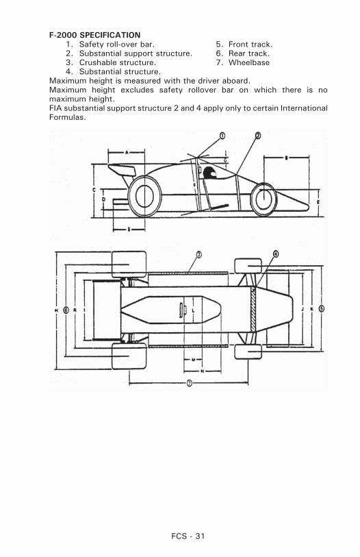
F-2000 SPECIFICATION 1. Safety roll-over bar. 5. Front track. 2. Substantial support structure. 6. Rear track. 3. Crushable structure. 7. Wheelbase 4. Substantial structure.Maximum height is measured with the driver aboard.Maximum height excludes safety rollover bar on which there is no maximum height.FIA substantial support structure 2 and 4 apply only to certain International Formulas.
FCS - 32
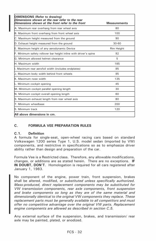
DIMENSIONS (Refer to drawing)Dimensions shown at the rear refer to the rearDimensions shown at the front refer to the front Measurements
A. Maximum rear overhang from rear wheel axis 80
B. Maximum front overhang from front wheel axis 100
C. Maximum height measured from the ground 90
D. Exhaust height measured from the ground 30-60
E. Maximum height of any aerodynamic Device Rim Height
F. Minimum safety rollover bar height inline with driver’s spine 92
G. Minimum allowed helmet clearance 5
H. Maximum width 185
I. Maximum rear aerofoil width (includes endplates) 95
J. Maximum body width behind front wheels 95
K. Maximum nose width 135
L. Minimum cockpit opening 45
M. Minimum cockpit parallel opening length 30
N. Minimum cockpit overall opening length 60
S. Maximum exhaust length from rear wheel axis 80
7. Minimum wheelbase 200
5. Minimum track 120
All above dimensions in cm.
C. FORMULA VEE PREPARATION RULES
C.1. DefinitionA formula for single-seat, open-wheel racing cars based on standard Volkswagen 1200 series Type 1, U.S. model sedan (imported by VW) components, and restrictive in specifications so as to emphasize driver ability rather than design and preparation of the car.
Formula Vee is a Restricted class. Therefore, any allowable modifications, changes, or additions are as stated herein. There are no exceptions. IF IN DOUBT, DON’T. Homologation is required for all cars registered after January 1, 1983.
No component of the engine, power train, front suspension, brakes shall be altered, modified, or substituted unless specifically authorized. Mass-produced, direct replacement components may be substituted for VW transmission components, rear axle components, front suspension and brake components so long as they are of the same material and dimensionally identical to the original VW components they replace. These replacement parts must be generally available to all competitors and must offer no competitive advantage over the original VW parts. Replacement engine components are allowed as described in section C.5.
Any external surface of the suspension, brakes, and transmission/ rear axle may be painted, plated, or anodized.
FCS - 33
Engine components shall be assembled in standard configuration. Exceeding the wear limits specified in the VW manual or other official VW guides is not prohibited provided that tolerances, dimensions, and specifications stated in the GCR are met.
C.2. Weight and DimensionsMinimum weight as qualified or raced, with driver: 1025 lbs..
Wheel base, Minimum: 81.5”Wheel base, Maximum: 83.5”Track, Front: Standard VW – Maximum 51.7” (No Spacers)Track, Rear: 49 13/16” + 1/8” - 5/8”Overall length, Minimum: 123” (includes exhaust)Overall length, Maximum: 127” (includes exhaust)Body depth at firewall, Minimum: 25”
C.3. Suspensiona. The front suspension and steering shall be standard VW Sedan
as defined herein, or an exact replica of the same material and dimensionally identical. The following modifications are allowed:
1. Removal of one torsion bar.
2. The use of any anti-sway bar(s), mounting hardware, and trailing arm locating spacers.
3. The use of any shock absorber(s) which can be mounted on the standard mounts. Spring shocks are prohibited.
4. Relocation of the steering gearbox to any position utilizing an appropriate mounting structure and replacements of the tie rods. Steering damper mount and/or the steering box locating bumps may be removed.
5. Steering column may be altered or replaced and any steering wheel may be used.
6. Use of any desired Pitman arm. Standard steering arms may be altered and speedometer cable hole may be plugged; however, no other modification of the spindle is permitted.
7. Modification of the standard front torsion bar(s).
8. The rubber portion only of the bump stop may be altered or removed.
9. Caster, camber and toe in/out settings are unrestricted. Clearancing of carrier or trailing arm to eliminate binding is permitted. Offset suspension bushings and alternate locating spacers are permitted.
10. Wheel tethers are recommended. If wheel tethers are used, a hole may be drilled in the spindle for the purpose of
FCS - 34
attachment.
11. Front end ride height adjuster(s) may be used provided they are not adjustable from the cockpit.
12. No structure, item, or component (including the battery) other than bodywork, can protrude further than ten (10) inches from the lower axle beam tube. Any item protruding further than eight (8) inches must include a vertical safety plate. This plate must be constructed of no less than .060” 6061-T-6 aluminum or no less than 16 gauge steel. The plate shall have a minimum frontal surface area of 42 square inches, and shall have a height of not less than four (4) inches and a width of not less than six (6) inches. The plate may have no more than ½ inch curvature or deflection from the horizontal or vertical plane, and shall be attached to the chassis (frame) at all four corners. The lower braces shall not exceed a 15-degree upward angle when measured from the horizontal plane of the lower frame tubes.
If a vented lead acid battery is mounted in front of the axle beam, it shall be encased in a marine-type container.
It is recommended that the front area of the nose be filled with foam to aid in impact absorption.
b. The rear axle assembly shall be standard VW sedan as defined herein with axle location provided by a single locating arm on each axle. The rear axle tube may be rotated about its axis. Coil spring(s) shall provide the primary springing medium, with telescopic shock absorber(s) mounted inside the spring(s). Cables, straps, or other positive stops may be used to limit positive camber. An anti-roll bar or camber control device may also be used. When said anti-roll bar or camber control device is removed, the required coil springs shall continue to perform functionally.
c. Wheels shall be standard fifteen (15) inch X 4J as used on the 1200cc and 1300cc VW sedan as defined herein, or the (15) inch X 4.5J. If (15) inch X 4.5J wheels are used, they shall be used as an axle set of two (2) wheels. The (15) inch X 4.5J wheel axle set may be front, rear, or both, but not side to side. Wheels may be balanced only by the use of standard automotive balance weights (adhesive or clip-on). Hub cap clips shall be removed.
d. Any tire size may be fitted, except that radial race tires (slicks) are not allowed.
C.4. Brakesa. Brake drums, backing plates, and wheel cylinders shall be
standard VW Sedan as defined herein, or an exact replica of the same material and dimensionally identical. Ribbed-type rear drums (VW Part # N113-501 615 D or ICP Part # 113 501 615
FCS - 35
D) may be used in place of the 1200 series rear brake drums.
b. These cars shall be equipped with a dual braking system operated by a single control. In case of a leak or failure at any point in the system, effective braking power shall be maintained on at least two wheels. Any master cylinder(s) may be used.
c. A separate hand brake (emergency brake) is not required. Removal of the hand brake and operating mechanism is permitted.
C.5. EngineThe engine shall be a standard VW power plant, as normally fitted to VW sedans as defined herein. Any engine part(s), listed by the manufacturer (VW) as a current, superseding, replacement part for the standard VW 1200 series, Type 1, U.S. model sedan and interchangeable with the original part(s), may be used. Turbocharging is not permitted.
The engine/transmission shall be mounted in the chassis with the transmission to the rear.
The following component parts may be replaced with that of other manufacture, provided said part is of the same material, is dimensionally identical, and meets all other tolerances and specifications stated in the GCR.
a. Engine Caseb. Cylinder Headsc. Cylinders (an O-ring for centering is permitted).d. Pistons and wrist pins - minimum combined weight without clips
or piston rings = 330.0 gramse. Cam followers - Minimum weight = 60.0 gramsf. Connecting rods with bolts and small end bushing - minimum
weight = 440.0 gramsg. Oil pump -- exact replica of any standard VW oil pumph. Distributori. Ignition pointsj. Distributor capk. Fuel pump - any standard type VW fuel pump which can be fitted
without modification of any other partl. Crankshaft - minimum weight sixteen (16) lbs..m. Crankshaft gearn. Flywheelo. Pressure plate, or alternate SACHS 211 141 025 DAM pressure
plate.p. Clutch discq. Throw out bearingr. Push rodss. Push rod tubes
Allowed:1. Removal of the carburetor air cleaner and choke
mechanism.
2. Replacement of standard exhaust system with any exhaust
FCS - 36
system terminating one (1) to three (3) inches behind the rearmost part of the body.
3. Lightening of the flywheel to a minimum of twelve (12) lbs..
4. Balancing of all moving parts of the engine, provided such balancing does not remove more material than is necessary to achieve the balance except on those component parts where weights are specified. The crankshaft may be ground and the case may be machined to accommodate the use of standard factory oversize/undersize crankshaft bearings, provided the crankshaft location is not changed.
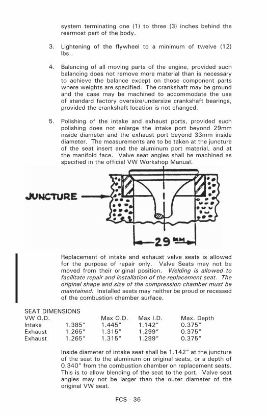
5. Polishing of the intake and exhaust ports, provided such polishing does not enlarge the intake port beyond 29mm inside diameter and the exhaust port beyond 33mm inside diameter. The measurements are to be taken at the juncture of the seat insert and the aluminum port material, and at the manifold face. Valve seat angles shall be machined as specified in the official VW Workshop Manual.
Replacement of intake and exhaust valve seats is allowed for the purpose of repair only. Valve Seats may not be moved from their original position. Welding is allowed to facilitate repair and installation of the replacement seat. The original shape and size of the compression chamber must be maintained. Installed seats may neither be proud or recessed of the combustion chamber surface.
SEAT DIMENSIONSVW O.D. Max O.D. Max I.D. Max. DepthIntake 1.385” 1.445” 1.142” 0.375” Exhaust 1.265” 1.315” 1.299” 0.375”Exhaust 1.265” 1.315” 1.299” 0.375”
Inside diameter of intake seat shall be 1.142” at the juncture of the seat to the aluminum on original seats, or a depth of 0.340” from the combustion chamber on replacement seats. This is to allow blending of the seat to the port. Valve seat angles may not be larger than the outer diameter of the original VW seat.
FCS - 37
6. Matching of manifold flanges is permitted.
7. Complete or partial removal of any cooling duct component. Removal of the fan and the fan housing. Fan belt origin is unrestricted. The use of a fan belt is optional.
8. Fitting of any standard Solex 28 PCI or 28 PICT carburetor. The use of any jets. Any venturi of standard VW/Solex dimensions, which may be fitted without alteration to the carburetor body. The venturi shall be fitted in the standard position, but its internal diameter may be machined. The carburetor may be rotated 180 degrees about its vertical axis. Modification of the float is allowed as long as no change is made to the float chamber and/or float valve.
Carburetor shall remain untouched with the following exceptions:
1. No material shall be added.
2. Bead-blasting is permitted for cleaning only.
3. Throttle shaft - Shall be a minimum of 0.185” with throttle plate installed. Machined sides shall remain flat and parallel with no chamfering or radiusing.
4. Throttle Plate - Shall be a minimum of 0.053”, flat and parallel with no chamfering or radiusing. Diameter shall be a minimum of 1.095”.
5. Carburetor Top - The junction of the bowl and bore may be radiused. The bore beneath the radius shall be a maximum of 1.120”. Accelerator pump boss shall remain original. The orifice in the base of the accelerator pump boss shall not allow a #56 (0.046”) drill bit to pass through (maximum hole diameter shall be less than 0.046”).
6. Carburetor Body - The removal of flashing from internal surfaces is permitted, but no additional material is to be removed from the casting in the area of the bore, emulsion tube carrier, or any carrier supports. Bore diameter from throttle shaft down shall not exceed 1.110”.
7. Fitting of any standard VW distributor (not restricted to 1200, series). Use of any standard six (6) or twelve (12) volt non-transistorized ignition coil. Mounting location is unrestricted.
8. The heat riser tube and heat sink shall be removed. Removal of metal from the interior of the intake manifold and the interior rust-proofed is permitted provided that
FCS - 38
the following dimensions are not exceeded.
Down Tube: The down tube shall be measured at two different locations within an area between .500” and 2.00” above the horizontal manifold tube. Each measurement shall be taken four (4) times, rotating around the circumference of the tube, and averaged. Averaged down tube dimension shall not exceed 1.140 inches O.D.
Horizontal Tube: The horizontal tube shall be measured at four different locations on each side of the down tube. The area to be measured on each side of the down tube is defined as being between the bend and a point that is 1.500” from the center of the down tube connection. Each measurement will be taken four (4) times, rotating around the circumference of the tube, and averaged. Averaged horizontal tube dimension shall not exceed 0.994 inches O.D.
The manifold shall not weigh less than twenty-four (24) ounces.
All exterior surfaces shall be in original condition and unpainted but may have a thin transparent coat of rust proofing material.
9. Voltage regulator, generator and/or generator stand may be removed.
10. The installation of baffles housed completely within the original oil sump and crankcase.
11. The use of oil temperature indicating device in the crankcase.
12. The use of any standard VW oil pump. The oil pump cover may be modified.
13. The use of valve spring shims.
14. The following standard dimensions and tolerances of engine components are included as information and shall be observed:
Maximum bore: 3.040 inches Stroke: 2.520 inches +/- 0.005 inch. Minimum capacity of combustion chamber in head: 43.0cc
(Polishing and/or tooling is prohibited.) Minimum depth, top of cylinder barrel to top of piston: 0.039 inch.
The above dimensions may be achieved by machining any previously machined surface, provided that the total surface is machined on the same plane as the previously machined surface. The above dimensions shall be the average of all
FCS - 39
four (4) cylinders.
15. The use of any VW clutch of the same diameter as fitted to standard VW sedan as defined herein. The standard clutch operating arm may be modified to allow its attachment in any appropriate position. Dowel pinning of the clutch pressure plate to the flywheel is permitted.
16. An oil sump extension may be fitted utilizing the oil strainer cover plate, provided the extension does not extend horizontally beyond the edge of the oil strainer cover plate and the capacity does not exceed 250cc. The oil pump pickup pipe may be extended into the sump extension. Accumulators (Accusump) may be fitted.
17. Replacement of oil galley plugs with threaded plugs.
18. The following standard dimensions are included for information only and shall be observed:
Exhaust valve diameter: 1.102 or 1.18 inches Intake valve diameter: 1.18 or 1.24 inches Reprofiling of valves is not permitted.
19. The crankcase may be machined to permit the use of standard VW camshaft bearing inserts, provided that camshaft location is not changed. The use of the two-relief valve crankcase, P/N 111-110-025E, is permitted.
20. Where minimum weights are specified, any lightening is permissible provided the original part complied with the dimensional restrictions set forth.
21. A VW “D” camshaft, Part Numbers 113-109-015D,113-109-017D,113-109-019D,113-109-021D,113-109-023D, 113-109-025D, 13-109-027D, or an exact replica of the same material and dimensionally identical shall be used. The maximum lift at the valve spring collar with zero valve clearance is:
with 1200 rocker arms -- Intake -- .334” + 0.000” with 1200 rocker arms -- Exhaust -- .3165” + 0.000” with 1300/1500 rocker arms -- Intake -- .354” + 0.000”with 1300/1500 rocker arms -- Exhaust -- .3365” + 0.000”
The camshaft profile shall match exactly those which are specified by the official SCCA camshaft plots, plus or minus .002 inch. It is permitted to regrind the camshaft to duplicate (but not exceed) the official SCCA profile. In so doing, the relationship between the centerlines of peak lift at the exhaust/intake lobes shall remain at 214 degrees fifteen (15) minutes, plus or minus one (1) degree. (Reference the Official SCCA Camshaft Checking Procedure). The camshaft timing may be changed in relationship to the crankshaft by utilizing
FCS - 40
an offset key at the crankshaft timing gear. Camshaft timing is unrestricted within the restrictions provided under 5.1 or as authorized above. The camshaft profile shall be checked using the official procedure published by the SCCA.
22. Installation of a spark plug hole repair utilizing standard thread repair methods, such as Helicoil, or welding and rethreading is permitted providing that the spark plug centerline is not changed.
23. A single standard automotive oil filter of not more than one quart total capacity, and a suitable mounting bracket and by-pass valve may be installed. Cooling fins are not permitted on any component. Only flexible unfinned maximum one inch outside diameter oil line (maximum length: twelve (12) feet) and suitable fittings may be used. Modification to the lubrication system to facilitate installation of the oil filter is permitted except that the standard oil cooler shall not be modified. All components shall be contained within the body to the rear of the firewall.
24. Alternate exhaust valves are allowed provided the dimensions and materials are the same as standard (VW) exhaust valves.
25. Any oil cooler is allowed. A total of twelve (12) feet of maximum one (1) inch O.D. oil line, unfinned, may be used to hook up the oil cooler and the oil filter (paragraph y). A small section of the fan shroud may be cut away to allow the oil cooler adapter to be mounted on the base pad of the standard oil cooler. Oil coolers shall be mounted completely inside a plumb line extending downward from the outermost edge of the bodywork.
26. An alternate oil pressure regulator spring may be used when original oil cooler is replaced with an alternate oil cooler.
27. Rocker arm wave type spacer washers may be replaced by solid steel type flat washers of suitable thickness.
28. Rocker arms may be lightened to a minimum weight of 80.0 grams. Must use only VW parts.
29. Valve springs are unrestricted providing:1. No more than one spring shall be used per valve.2. The standard spring cap and retainers shall be used.3. Spring shall be made of steel.
30. Valve covers are unrestricted and may be bolted on.
31. Crankshaft pulley is unrestricted.
32. Rocker arm shafts may be modified or replaced by those of other manufacture, including shafts that replace the
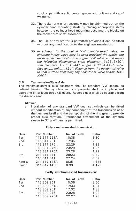
FCS - 41
stock clips with a solid center spacer and bolt on end caps/washers.
33. The rocker arm shaft assembly may be shimmed out on the cylinder head mounting studs by placing appropriate shims between the cylinder head mounting boss and the blocks on the rocker arm shaft assembly.
34. The use of any starter is permitted provided it can be fitted without any modification to the engine/transmission.
35. In addition to the original VW manufactured valve, an alternate intake valve may be used provided the profile and finish remain identical to the original VW valve, and it meets the following dimensions: stem diameter: .3126-.3130”, seat diameter: 1.236-1.244”, length: 4.386-4.417”, valve face length (min.): .124”, distance from the bottom of valve to seat surface (including any chamfer at valve head): .031-.060”.
C.6. Transmission/Rear AxleThe transmission/rear axle assembly shall be standard VW sedan, as defined herein. The synchromesh components shall be in place and operating on at least three (3) gears. Reverse gear shall be operable from the driver’s seat.
Allowed:a. Installation of any standard VW gear set which can be fitted
without modification of any component of the transmission or of the gear set itself and the transposing of the ring gear to provide proper axle rotation. Permanent attachment of the synchro sleeve to 3rd & 4th gear is permitted.
Fully synchromeshed transmission:
Gear Part Number No. of Teeth Ratio1st 113 311 251A 10:38 3.80 2nd 113 311 261 17:35 2.063rd 113 311 275 22:29 1.32 113 331 275B 23:29 1.26 113 331 275A 23:28 1.224th 211 311 341 28:23 0.82 113 311 341 27:24 0.89Ring & 211 517 143A 8:35 4.375Pinion 311 517 143B 8:33 4.125
Partly synchromeshed transmission:
Gear Part Number No. of Teeth Ratio1st 113 309 251 10:36 3.602nd 113 309 261A 17:33 1.94 113 309 261 17:32 1.883rd 113 309 275 23:28 1.22 113 309 275A 22:27 1.23
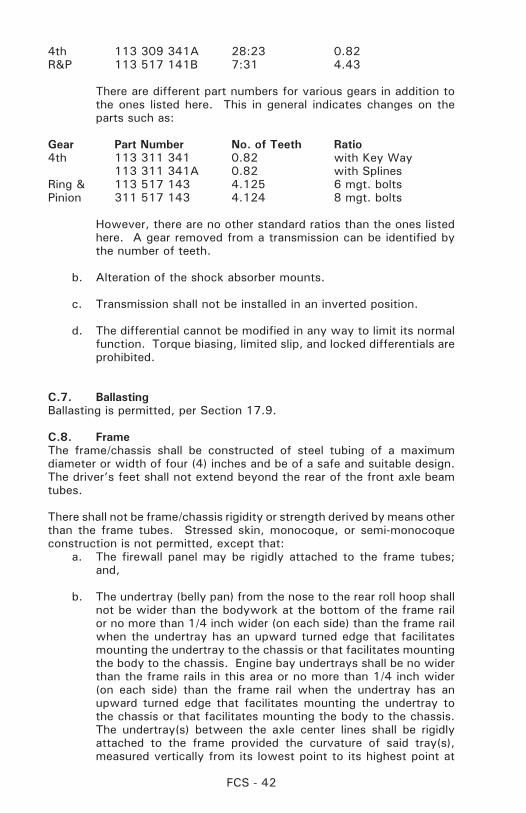
FCS - 42
4th 113 309 341A 28:23 0.82R&P 113 517 141B 7:31 4.43
There are different part numbers for various gears in addition to the ones listed here. This in general indicates changes on the parts such as:
Gear Part Number No. of Teeth Ratio4th 113 311 341 0.82 with Key Way 113 311 341A 0.82 with SplinesRing & 113 517 143 4.125 6 mgt. boltsPinion 311 517 143 4.124 8 mgt. bolts
However, there are no other standard ratios than the ones listed here. A gear removed from a transmission can be identified by the number of teeth.
b. Alteration of the shock absorber mounts.
c. Transmission shall not be installed in an inverted position.
d. The differential cannot be modified in any way to limit its normal function. Torque biasing, limited slip, and locked differentials are prohibited.
C.7. BallastingBallasting is permitted, per Section 17.9.
C.8. FrameThe frame/chassis shall be constructed of steel tubing of a maximum diameter or width of four (4) inches and be of a safe and suitable design. The driver’s feet shall not extend beyond the rear of the front axle beam tubes.
There shall not be frame/chassis rigidity or strength derived by means other than the frame tubes. Stressed skin, monocoque, or semi-monocoque construction is not permitted, except that:
a. The firewall panel may be rigidly attached to the frame tubes; and,
b. The undertray (belly pan) from the nose to the rear roll hoop shall not be wider than the bodywork at the bottom of the frame rail or no more than 1/4 inch wider (on each side) than the frame rail when the undertray has an upward turned edge that facilitates mounting the undertray to the chassis or that facilitates mounting the body to the chassis. Engine bay undertrays shall be no wider than the frame rails in this area or no more than 1/4 inch wider (on each side) than the frame rail when the undertray has an upward turned edge that facilitates mounting the undertray to the chassis or that facilitates mounting the body to the chassis. The undertray(s) between the axle center lines shall be rigidly attached to the frame provided the curvature of said tray(s), measured vertically from its lowest point to its highest point at
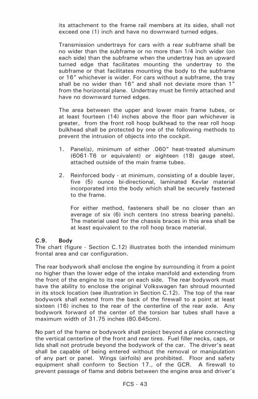
FCS - 43
its attachment to the frame rail members at its sides, shall not exceed one (1) inch and have no downward turned edges.
Transmission undertrays for cars with a rear subframe shall be no wider than the subframe or no more than 1/4 inch wider (on each side) than the subframe when the undertray has an upward turned edge that facilitates mounting the undertray to the subframe or that facilitates mounting the body to the subframe or 16” whichever is wider. For cars without a subframe, the tray shall be no wider than 16” and shall not deviate more than 1” from the horizontal plane. Undertray must be firmly attached and have no downward turned edges.
The area between the upper and lower main frame tubes, or at least fourteen (14) inches above the floor pan whichever is greater, from the front roll hoop bulkhead to the rear roll hoop bulkhead shall be protected by one of the following methods to prevent the intrusion of objects into the cockpit.
1. Panel(s), minimum of either .060” heat-treated aluminum (6061-T6 or equivalent) or eighteen (18) gauge steel, attached outside of the main frame tubes.
2. Reinforced body - at minimum, consisting of a double layer, five (5) ounce bi-directional, laminated Kevlar material incorporated into the body which shall be securely fastened to the frame.
For either method, fasteners shall be no closer than an average of six (6) inch centers (no stress bearing panels). The material used for the chassis braces in this area shall be at least equivalent to the roll hoop brace material.
C.9. BodyThe chart (figure - Section C.12) illustrates both the intended minimum frontal area and car configuration.
The rear bodywork shall enclose the engine by surrounding it from a point no higher than the lower edge of the intake manifold and extending from the front of the engine to its rear on each side. The rear bodywork must have the ability to enclose the original Volkswagen fan shroud mounted in its stock location (see illustration in Section C.12). The top of the rear bodywork shall extend from the back of the firewall to a point at least sixteen (16) inches to the rear of the centerline of the rear axle. Any bodywork forward of the center of the torsion bar tubes shall have a maximum width of 31.75 inches (80.645cm).
No part of the frame or bodywork shall project beyond a plane connecting the vertical centerline of the front and rear tires. Fuel filler necks, caps, or lids shall not protrude beyond the bodywork of the car. The driver’s seat shall be capable of being entered without the removal or manipulation of any part or panel. Wings (airfoils) are prohibited. Floor and safety equipment shall conform to Section 17., of the GCR. A firewall to prevent passage of flame and debris between the engine area and driver’s
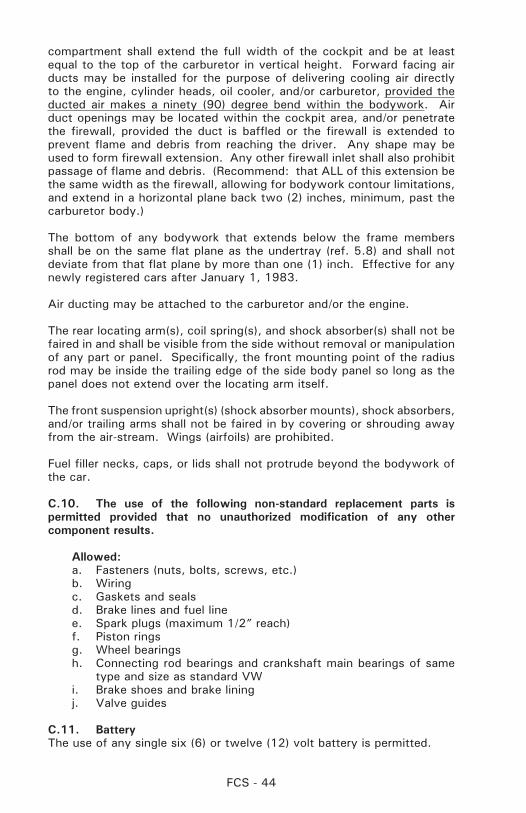
FCS - 44
compartment shall extend the full width of the cockpit and be at least equal to the top of the carburetor in vertical height. Forward facing air ducts may be installed for the purpose of delivering cooling air directly to the engine, cylinder heads, oil cooler, and/or carburetor, provided the ducted air makes a ninety (90) degree bend within the bodywork. Air duct openings may be located within the cockpit area, and/or penetrate the firewall, provided the duct is baffled or the firewall is extended to prevent flame and debris from reaching the driver. Any shape may be used to form firewall extension. Any other firewall inlet shall also prohibit passage of flame and debris. (Recommend: that ALL of this extension be the same width as the firewall, allowing for bodywork contour limitations, and extend in a horizontal plane back two (2) inches, minimum, past the carburetor body.)
The bottom of any bodywork that extends below the frame members shall be on the same flat plane as the undertray (ref. 5.8) and shall not deviate from that flat plane by more than one (1) inch. Effective for any newly registered cars after January 1, 1983.
Air ducting may be attached to the carburetor and/or the engine.
The rear locating arm(s), coil spring(s), and shock absorber(s) shall not be faired in and shall be visible from the side without removal or manipulation of any part or panel. Specifically, the front mounting point of the radius rod may be inside the trailing edge of the side body panel so long as the panel does not extend over the locating arm itself.
The front suspension upright(s) (shock absorber mounts), shock absorbers, and/or trailing arms shall not be faired in by covering or shrouding away from the air-stream. Wings (airfoils) are prohibited.
Fuel filler necks, caps, or lids shall not protrude beyond the bodywork of the car.
C.10. The use of the following non-standard replacement parts is permitted provided that no unauthorized modification of any other component results.
Allowed:a. Fasteners (nuts, bolts, screws, etc.)b. Wiringc. Gaskets and sealsd. Brake lines and fuel linee. Spark plugs (maximum 1/2” reach)f. Piston ringsg. Wheel bearingsh. Connecting rod bearings and crankshaft main bearings of same
type and size as standard VWi. Brake shoes and brake liningj. Valve guides
C.11. BatteryThe use of any single six (6) or twelve (12) volt battery is permitted.
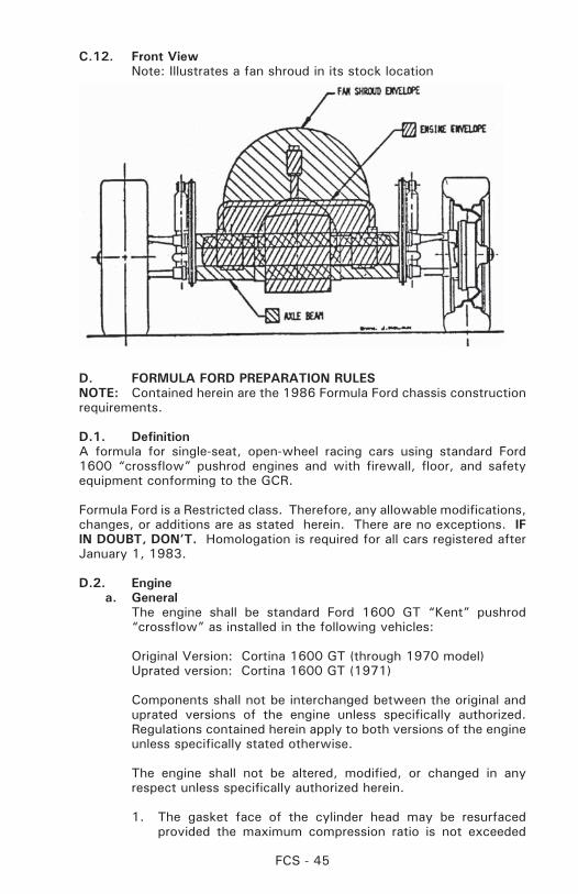
FCS - 45
C.12. Front View Note: Illustrates a fan shroud in its stock location
D. FORMULA FORD PREPARATION RULESNOTE: Contained herein are the 1986 Formula Ford chassis construction requirements.
D.1. DefinitionA formula for single-seat, open-wheel racing cars using standard Ford 1600 “crossflow” pushrod engines and with firewall, floor, and safety equipment conforming to the GCR.
Formula Ford is a Restricted class. Therefore, any allowable modifications, changes, or additions are as stated herein. There are no exceptions. IF IN DOUBT, DON’T. Homologation is required for all cars registered after January 1, 1983.
D.2. Enginea. General The engine shall be standard Ford 1600 GT “Kent” pushrod
“crossflow” as installed in the following vehicles:
Original Version: Cortina 1600 GT (through 1970 model) Uprated version: Cortina 1600 GT (1971)
Components shall not be interchanged between the original and uprated versions of the engine unless specifically authorized. Regulations contained herein apply to both versions of the engine unless specifically stated otherwise.
The engine shall not be altered, modified, or changed in any respect unless specifically authorized herein.
1. The gasket face of the cylinder head may be resurfaced provided the maximum compression ratio is not exceeded
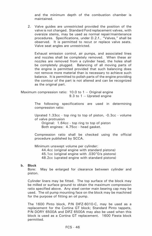
FCS - 46
and the minimum depth of the combustion chamber is maintained.
2. Valve guides are unrestricted provided the position of the valve is not changed. Standard Ford replacement valves, with oversize stems, may be used as normal repair/maintenance procedures. Specifications, under D.2.f., “Valves,” shall be observed. It is permitted to recut or replace valve seats. Valve seat angles are unrestricted.
Exhaust emission control, air pumps, and associated lines and nozzles shall be completely removed. When these air nozzles are removed from a cylinder head, the holes shall be completely plugged. Balancing of all moving parts of the engine is permitted provided that such balancing does not remove more material than is necessary to achieve such balance. It is permitted to polish parts of the engine providing the contour of the part is not altered and can be recognized as the original part.
Maximum compression ratio: 10.0 to 1 -- Original engine 9.3 to 1 -- Uprated engine
The following specifications are used in determining compression ratio:
Uprated 1.33cc - top ring to top of piston, -0.3cc - volume of valve protrusion
Original: 1.64cc - top ring to top of piston Both engines: 4.75cc - head gasket.
Compression ratio shall be checked using the official procedure published by SCCA.
Minimum unswept volume per cylinder: 44.4cc (original engine with standard pistons) 45.1cc (original engine with .030”0/s pistons) 48.2cc (uprated engine with standard pistons)
b. Block Bore: May be enlarged for clearance between cylinder and
piston.
Cylinder liners may be fitted. The top surface of the block may be milled or surface ground to obtain the maximum compression ratio specified above. Any steel center main bearing cap may be used. The oil pump mounting face on the block may be machined for the purpose of fitting an oil pump.
The 1600 Pinto block, P/N DIFZ-6010-C, may be used as a replacement for the Cortina GT block; Standard Pinto tappets, P/N DORY 6500A and DIFZ 6500A may also be used when this block is used as a Cortina GT replacement. 1600 Fiesta block permitted.
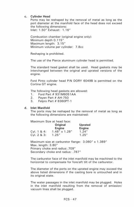
FCS - 47
c. Cylinder Head Ports may be reshaped by the removal of metal as long as the
port diameter at the manifold face of the head does not exceed the following dimensions:
Inlet: 1.50” Exhaust: 1.16”
Combustion chamber (original engine only): Minimum depth 0.115” Maximum length: 3.15” Minimum volume per cylinder: 7.8cc
Reshaping is prohibited.
The use of the Pierce aluminum cylinder head is permitted.
The standard head gasket shall be used. Head gaskets may be interchanged between the original and uprated versions of the engine.
Ford Pinto cylinder head P/N DORY 6049B is permitted on the Cortina GT engine.
The following head gaskets are allowed: 1. Ford Part # 931M6051AA 2. Payen Part # AH-750 3. Felpro Part # 8360PT-1
d. Inlet Manifold The ports may be reshaped by the removal of metal as long as
the following dimensions are maintained:
Maximum Size at head face: Original Uprated Engine Engine Cyl. 1 & 4: 1.48” x 1.28” 1.24” Cyl. 2 & 3: 1.25” 1.25”
Maximum size at carburetor flange: 3.060” x 1.389” Max. length: 3.80” Primary choke end radius:.709” Secondary choke end radius: .787”
The carburetor face of the inlet manifold may be machined to the horizontal to compensate for fore/aft tilt of the carburetor.
The diameter of the ports on the uprated engine may exceed the above listed dimensions if the casting bore is untouched and in its original state.
The water passages in the inlet manifold may be plugged. Holes in the inlet manifold resulting from the removal of emission/vacuum lines shall be plugged.
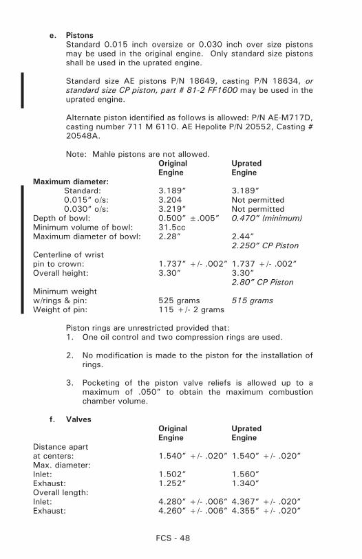
FCS - 48
e. Pistons Standard 0.015 inch oversize or 0.030 inch over size pistons
may be used in the original engine. Only standard size pistons shall be used in the uprated engine.
Standard size AE pistons P/N 18649, casting P/N 18634, or standard size CP piston, part # 81-2 FF1600 may be used in the uprated engine.
Alternate piston identified as follows is allowed: P/N AE-M717D, casting number 711 M 6110. AE Hepolite P/N 20552, Casting # 20548A.
Note: Mahle pistons are not allowed. Original Uprated Engine EngineMaximum diameter: Standard: 3.189” 3.189” 0.015” o/s: 3.204 Not permitted 0.030” o/s: 3.219” Not permittedDepth of bowl: 0.500” ±.005” 0.470” (minimum)Minimum volume of bowl: 31.5ccMaximum diameter of bowl: 2.28” 2.44” 2.250” CP PistonCenterline of wristpin to crown: 1.737” +/- .002” 1.737 +/- .002” Overall height: 3.30” 3.30” 2.80” CP PistonMinimum weightw/rings & pin: 525 grams 515 gramsWeight of pin: 115 +/- 2 grams
Piston rings are unrestricted provided that:1. One oil control and two compression rings are used.
2. No modification is made to the piston for the installation of rings.
3. Pocketing of the piston valve reliefs is allowed up to a maximum of .050” to obtain the maximum combustion chamber volume.
f. Valves Original Uprated Engine EngineDistance apartat centers: 1.540” +/- .020” 1.540” +/- .020”Max. diameter:Inlet: 1.502” 1.560”Exhaust: 1.252” 1.340”Overall length:Inlet: 4.280” +/- .006” 4.367” +/- .020”Exhaust: 4.260” +/- .006” 4.355” +/- .020”
FCS - 49
Reshaping of the valves is specifically prohibited.
Alternate valve AE p/n V34524 (intake), V34525 (exhaust) are permitted.
g. Camshaft The camshaft lobe profile shall not be altered. The following
specifications are provided for checking purposes: Lobes, heel to toe: Inlet: 1.311” Maximum Exhaust: 1.312” Maximum
Lobes, base circle radius: Inlet: 0.540” Exhaust: 0.545”
Lift at top of pushrod: Inlet: 0.231” +/- .002” Maximum Exhaust: 0.232” +/-.002” Maximum Lift at spring cap: Inlet: 0.356” Maximum (Zero tappet setting) Exhaust: 0.358” Maximum
Note: Recontouring of the valve stem contact pad of the rocker arm is permitted, provided the maximum lift at the spring cap is not exceeded.
Offset camshaft/sprocket dowels are permitted.
Camshaft profile and lobe centers shall be checked using the official procedure published by SCCA.
A camshaft that is a replica of the original camshaft and of the same material and dimensionally identical may be used.
h. Valve Springs Valve springs and valve spring shims are unrestricted:
1. No more than one spring shall be used per valve.
2. The standard spring cap and retainers shall be used.
3. Spring shall be made of steel.
i. Pushrod Original Engine Minimum stem diameter: 0.25” Overall length: 7.64” Minimum Minimum weight: 50 grams
j. Connecting Rods Minimum weight: Both engines: 630 grams (Note: Weights include cap, bolts, and small end bush, but not
big end bearing shells).
FCS - 50
k. Crankshaft (Fiesta crankshaft permitted) Alternate cast steel crankshaft is permitted with same weight as
stock crankshaft.
Weight: Original engine: 23 lbs. 8 oz. Minimum Uprated and Fiesta Crankshaft: 24 lbs. 8 oz. Minimum Stroke (at piston): 3.056” +/- .004” Crankshaft pulley: unrestricted. Either crankshaft may be used in either engine. The crankshaft may be shot peened.
l. Flywheel Weight with ring gear: 15.5 lbs minimum for the original and uprated engine.
The flywheel may be machined provided the machining to reduce weight to the above minimum weight retains the standard profile. Flywheel locating dowels are permitted.
An alternate flywheel from JAE, part # JAE1600 is also allowed to the above weight of 15.5 lbs.
m. Carburetor Original Engine: Weber 32 DFM or DFD or Holley 5200
Venturi Diameter: Primary: 26mm Secondary: 27mm
Uprated (Kent) Engine: Weber 32/36 DGV or Holley 5200
Venturi diameter: Primary: 26mm Secondary: 27mm
1. The fitting of any jets (including accelerator pump discharge nozzle) which may be fitted without modification to the carburetor body.
2. Modification or substitution of external throttle linkage.
3. The fitting of internal and/or external anti-surge pipes.
4. The removal of the air cleaner.
5. The fitting of a velocity stack (intake air horn).
6. The removal of the choke butterflies and linkage.
7. An alternate carburetor gasket is permitted provided it is the same thickness as the original gasket.
8. The carburetor housing may be modified for the installation of throttle shaft bearings provided the modification serves no other purpose.
FCS - 51
n. Fuel Pump: Unrestricted
o. Exhaust Manifold: Unrestricted
p. Lubrication System Oil pump and sump: Unrestricted Dry sump system is permitted.
q. Cooling System Radiator, fan, and water pump: Unrestricted Pump/fan/generator drive belt: Unrestricted
r. Electrical Equipment Distributor: Distributors are unrestricted provided the original
drive, location, and housing (standard Motorcraft, Bosch, or Lucas) are retained. The distributor is defined as the component that triggers the LT current and distributes the HT current. The ignition timing may only be varied by vacuum and/or mechanical means. It is prohibited to use any other method or component to trigger, distribute, or time the ignition. Standard Motorcraft (Autolite), Bosch, or Lucas. The vacuum advance mechanism may be removed, and the distributor advance plate may be secured by soldering or welding or by suitable fasteners. The advance curve and advance springs are unrestricted. Generator/ Alternators: not required. All other electrical components are unrestricted.
s. Miscellaneous1. The timing chain/sprocket cover may be altered or replaced.
2. The use of the following non-standard replacement parts is permitted provided their use does not result in any unauthorized modification of any other component:
A. Fasteners (nuts, bolts, screws, studs, etc.) except intake manifold fasteners. Intake manifold fasteners may be of either a socket head or hex head configuration.
B. Gaskets, except head gasket, carburetor to inlet manifold gasket, and inlet manifold to head gasket. Carburetor to inlet manifold gasket as used with Holley 5200 is allowed.
C. Washers.
D. Seals.
E. Connecting rod, crankshaft, and camshaft bearings of the same size and type as original. Normal oversize/undersize bearings are permitted. This does not allow reducing the bearing surface area by reducing the width of standard bearings.
F. Spark plugs.
FCS - 52
G. Rocker pedestals that are of the same material and dimensionally identical (i.e. shaft location, offset, etc.) to the original components may be used.
3. Mechanical tachometer drive is permitted.
4. The crankcase breather may be altered or removed.
5. The rocker cover may be altered to provide for crankcase ventilation, and the filler cap may be altered or replaced.
6. The crankshaft and main bearing caps may be treated with salt-bath nitriding cover under SAE specification AMS 2755A (tuftriding, etc.)
7. The use of any oil or lubricants.
8. Valve or rocker covers may be substituted, provided that the replacement cover affords no additional function than that of the original stock cover.
9. Water pump, fan, and generator/alternator pulley(s) are unrestricted.
10 Exhaust Outlets
Exhaust outlets on cars registered after January 1, 1996 shall not extend more than 60cm (23.60”) behind the centerline of the rear axle and shall be positioned between 30cm (11.8”) and 60cm (23.6”) from the ground, measured to the bottom of the exhaust pipe.
11. Exhaust Outlets: Cars registered prior to January 1, 1986.
A. It is recommended that all exhaust outlets be no longer than 60cm (23.60”) behind the centerline of the rear axle and positioned between 30cm (11.8”) and 60cm (23.6”) from the ground.
B. For cars unable to comply with the above rule (A.), they shall have a support bracket that attaches within six (6) inches of the outlet end, and the support bracket shall extend no more than thirty (30) degrees from vertical to the rear. Beginning January 1, 1986, it is mandatory for all Formula Ford cars.
D.3. TransmissionAny transmission may be used with not more than four (4) forward gears and an operational reverse gear.
a. The use of automatic and/or sequentially shifted gearbox is prohibited.
b. Electronic assisted gear change mechanisms and electronically
FCS - 53
controlled differentials are prohibited.
c. Gearboxes with shafts that are transverse to the longitudinal axis of the chassis are not allowed. The sole exception are the gearbox final drive (crownwheel) shaft axis and final drive shafts (half shafts). All change gears must be located in the case aft of the final drive.
D.4. Final DriveAny final drive unit may be used except:
a. Drive shall be to rear wheels only.
b. The differential cannot be modified in any way to limit its normal function. Torque biasing, limited slip, and locked differentials are prohibited.
D.5. ClutchThe use of any single plate clutch is permitted provided no modification is made to the flywheel other than changing the points of attachment of the clutch to the flywheel, and provided that it shall have an operable clutch system. Carbon Fiber clutches are not permitted.
D.6. Chassis/FrameFormula Ford 1986 construction requirements as of January 1, 1986. All new Formula Ford cars are to be built to these specifications covered in D.6., through D.7.h.. (Required for Formula 2000 also.)
a. The chassis shall be of steel space frame construction. Monocoque-type structures are prohibited. Stabilized (honeycomb) or composite (carbon fiber or Kevlar) materials are not permitted, except as specifically authorized within these rules. The frame shall incorporate a roll cage per Section 18., (revised January 1, 1984). Forward-facing braces protecting the driver’s legs and feet shall extend from the front roll hoop to the front bulkhead. (The front bulkhead is defined as the furthest forward transverse section of the main frame.) The soles of the driver’s feet shall not extend beyond the front edge of the wheel rims (in normal position; i.e., pedals not depressed) and shall remain behind the front bulkhead. The lower main frame rails shall be a minimum of twenty-five (25) centimeters (9.84”) apart (inside dimension) from the front bulkhead to the rear roll hoop.
b. There shall be a crushable structure, securely attached to the front bulkhead, with a minimum cross section of 200 sq. cm (31 sq. in.), 40cm (15.75”) forward of the clutch and brake pedals (not depressed)constructed of a minimum of eighteen (18) gauge 6061-T4 or equivalent aluminum.
Radiators may be incorporated in this structure.
c. The area between the upper and lower main frame tubes from the front roll hoop bulkhead to the rear roll hoop bulkhead shall be protected by one of the following methods to prevent the intrusion of objects into the cockpit.
FCS - 54
1. Panel(s), minimum of either .060” heat treated aluminum (6061-T6 or equivalent) or eighteen (18) gauge steel, attached outside of the main frame tubes.
2. Reinforced body - at minimum, consisting of a double layer, five (5) oz., bi-directional, laminated Kevlar material incorporated into the body which shall be securely fastened to the frame.
For either method, fasteners shall be no closer than six (6) inch centers (no stress-bearing panels). The material used for the chassis braces in this area shall be at least equivalent to the roll hoop brace material.
d. A stress-bearing floor pan/undertray, minimum of .060” heat treated aluminum or eighteen (18) gauge steel, is required from the front bulkhead to the rear roll hoop bulkhead. Its curvature shall not exceed one inch.
Sheet materials attached to the frame by welding, bonding, or by rivets or threaded fasteners which are located closer than six (6) inch centers, are defined as stress-bearing panels. Composite or stabilized materials shall not be used for stress-bearing panels. The mountings for brake and clutch pedals and cylinders (front bulkhead), instruments, (front roll hoop bulkhead), and rear roll hoop bulkhead (behind the driver) may also be stress-bearing panels. No other stress-bearing panels are permitted.
The firewall portion of the rear roll hoop bulkhead (panel) shall extend the full width of the cockpit and be at least equal to the top of the carburetor in vertical height. Forward facing air ducts may be installed for the purpose of delivering air directly to the engine area. Air duct openings may be located within the cockpit provided the firewall is extended to prevent flame and debris from reaching the driver. (Any shape may be used to form firewall extension.) All firewall inlets shall prohibit passage of flame and debris.
Brackets for mounting components, such as the engine, transmission, suspension pickups, instruments, clutch and brake components, and body panels may be nonferrous, of any shape, and fastened to the frame in any manner.
D.7. Bodyworka. The bodywork opening giving access to the cockpit shall have
the following minimal dimensions: Length: 60cm (23.622 inches) Width: 45cm (17.717 inches) This width extends over a length
of 30cm (11.811 inches) minimum. This minimal rectangular opening may exist anywhere forward of the bracing, and required padding will not be considered in these dimensions.
b. The driver’s seat shall be capable of being entered without the manipulation or removal of any part or panel.
FCS - 55
c. Bodywork (including fuel tanks) shall not exceed a maximum width of 95cm (37.44 inches). No part of the bodywork, rear spoiler, or exhaust system shall extend more than 100cm (39 inches) behind the centerline of the rear axle. Bodywork shall not increase in width behind the centerline of the rear axle in any horizontal section. There shall be no forward facing gaps or openings in the bodywork with the exception of those necessary for engine cooling, engine air inlet, shock, or brake cooling. All bodywork shall be firmly attached to the chassis. Wings and other airfoil devices which create aerodynamic downforce are prohibited. No extension of the undertray or attached components for the purpose of downforce or ground effects are permitted. Any part of the car which has an influence on the aerodynamic stability of the vehicle shall be firmly attached with no provisions for adjustment to vary downforce, except that a single rear spoiler, which may be capable of adjustment, is permitted. Cockpit adjustment is not permitted. This spoiler shall be no wider than the surface to which it is attached, and there shall be no gap between the spoiler and the body surface to which it is attached.
d. No part of the bodywork or rear spoiler shall exceed the height of a horizontal plane 90cm (35.4 inches) above the ground, with the car as qualified or raced, with driver aboard. The safety roll bar/roll cage and engine air box are not included in this height restriction.
e. It is the intent of these rules to minimize the use of “ground effects” to achieve aerodynamic downforce on the vehicle. Thus, for the full width of the body between the front and rear axles, the lower surface (surface licked by the airstream) shall not exceed 2.54cm (1 inch) deviation from the horizontal in any longitudinal section through that surface. (This is not to be interpreted as requiring a floor pan beneath the motor, transaxle, transmission, or final drive housing.) Diffuser undertrays or venturi tunnels are prohibited. No aerodynamic devices (e.g., skirts, body sides, etc.) may extend more than 1cm (0.394 inches) below the lower surface of the floor pan to the rear of the front axle. Seat buckets or other protrusions shall not circumvent this rule. It is not permitted to duct air through any part of the bodywork for the purpose of providing aerodynamic downforce on the car. All ducted air for heat exchangers (water/oil) shall pass through those heat exchangers.
f. Fuel filler necks, caps, or lids shall not protrude beyond the bodywork of the car.
g. Fuel cell air vents shall be located at least 25cm (9.84 inches) to the rear of the cockpit. Safety fuel cell requirements per GCR Section 19..
h. Carbon fiber is not permitted.
FCS - 56
D.8. SuspensionSuspension is defined as the system of springs, shock absorbers, control arms, links, etc., supporting the vehicle on its axles. Sway bars, sway bar links, steering components, etc., are not classified as suspension for this discussion.
All suspension components shall be of steel or ferrous material, with the exception of hubs, hub adapters, hub carriers, bell cranks, pivot blocks, bearings, and bushings. Front and rear hub carriers shall be only steel or aluminum alloy for cars manufactured after January 1, 1983. Springs shall be steel only.
Control arms and all associated items which attach directly to the chassis members shall be boxed in or captured to prevent intrusion into the cockpit.
Shock absorbers: Design - unrestricted; Casing Material steel or aluminum alloy.
All components which are not defined as chassis/frame or suspension are unrestricted, unless otherwise restricted by these rules or the GCR. Titanium is prohibited.
It is not permitted to attach spoilers, fairings, or other devices which may exert downforce to the movable suspension members. If the suspension member is of streamline or airfoil cross section, it shall be symmetrical about its horizontal axis. Brake lines may be attached to the suspension.
D.9. BrakesUnrestricted, except that calipers shall be cast iron, and rotors are restricted to ferrous material.
Forward facing brake cooling ducts may be installed, but shall serve no other function or purpose.
D.10. WheelsWheels are unrestricted except that:
a. Material is unrestricted providing it is metal.
b. Diameter shall be thirteen (13) inches.
c. Rim width shall not exceed 5.5 inches.
d. Wheel covers, wheel fans, or any device to fair in the wheel is prohibited.
D.11. Weight Minimum weight as qualified or raced, with driver: 1050 lbs. - Original Engine 1100 lbs. - Uprated Engine
D.12. TiresPer Section 11.2.1.D of the GCR
FCS - 57
D.13. Cars Registered Prior To 1/1/86The following specifications are for cars registered prior to January 1, 1986 and for Technical Inspection only. No cars are to be built to these specifications as of January 1, 1986.
A. Chassis/Frame The chassis is defined as the frame. It shall be a steel space
frame. Monocoque-type structures are prohibited. Sheet material affixed to the frame by welding, bonding, or riveting, or by bolts or screws which are six (6) inch centers are defined as stress-bearing panels.
The undertray, for safety reasons, shall be a stress-bearing panel. Its curvature shall not exceed one (1) inch. The mountings for brake and clutch pedals and cylinders, and for the instrument panel and the bulkhead (panel) behind the driver may be stress-bearing. No other stress-bearing panels are permitted.
Brackets for mounting components, such as the engine, transmission, suspension pick-ups, instruments, clutch, and brake components, and body panels may be non-ferrous, of any shape, and fastened to the frame in any manner.
Gussets are defined as of steel, fastened to a maximum of two (2) members, and are specifically permitted.
The firewall portion of the bulkhead (panel) shall extend the full width of the cockpit and be as high as the top of the carburetor. Forward facing air ducts may be installed for the purpose of delivering air directly to the engine area. Air duct openings may be located within the cockpit provided the firewall is extended to prevent flame and debris from reaching the driver. (Any shape may be used to form firewall extension.) All firewall inlets shall prohibit passage of flame and debris.
B. Suspension and Running Gear Suspension is defined as the system of springs, shock absorbers,
A-arms, links, etc., supporting the vehicle on its axles. Sway bars, sway bar links, steering rack housings, steering links, etc., are not classified as suspension or running gear for this application.
All components shall be of steel, with the exception of hubs, hub adapters, rear hub carriers, and bearings and bushings. Front hub carrier material shall be of steel or aluminum alloy. The materials for front and rear hub carriers on cars manufactured after January 1, 1983 will be only steel or aluminum alloy. Springs: steel only, titanium is prohibited.
Shock absorbers: Design: Unrestricted. Casing Material: Steel or aluminum alloy.
All components which are not defined as chassis/frame or
FCS - 58
suspension or running gear are unrestricted, unless otherwise restricted by the GCR. Titanium is prohibited.
C. Body1. Definition of Bodywork Internally: All visible parts of the passenger compartment.
a. The bodywork opening giving access to the cockpit shall have the following minimal dimensions:
Length: 60cm (23.622 inches) Width: 45cm (17.72 inches)
This width extends over a length of 30cm (11.811 inches) minimum. This minimal rectangular opening may exist anywhere forward of the firewall. Forward facing roll bar/cage bracing and required padding will not be considered in these dimensions.
b. The driver’s seat shall be capable of being entered without the manipulation or removal of any part or panel.
c. Bodywork, including fuel tanks, shall not exceed a maximum width of 95cm (37.4 inches).
d. No part of the bodywork and aerodynamic devices shall exceed the height of a horizontal plane 90cm (35.4 inches) above the ground. The safety roll bar/roll cage and engine air box are not included in this height restriction. Measurements are to be made in any condition, driver on board.
e. No part of the bodywork shall extend more than 100cm (39 inches) behind the centerline of the rear axles.
f. Any specific part of the car which has an aerodynamic influence on the stability of the vehicle shall be firmly fixed with no provisions for adjustment to vary downforce.
g. Side-mounted radiators (behind the front wheels) may extend beyond the 95cm (37.4 inches) limitation, but not beyond a vertical plane passing through the centerlines of the front and rear tires. Any portion of a radiator that extends beyond the 95cm (37.4 inches) limitation cannot be covered with any type of shrouding. Radiators mounted in front of the front wheels are considered front mounted and cannot exceed the 95cm (37.4 inches) limitation.
2. Wings and other airfoil devices which have the principal effect of creating aerodynamic down-thrust are prohibited. Airfoil: Any device or part of a car (excepting normal and conventionally styled bodywork) which has a principal effect
FCS - 59
of creating aerodynamic downthrust. Within this definition may be included forward facing gaps or openings in the bodywork, but shall not include spoilers in the form of raised surfaces, continuous with the body surface, and not wider than the body surface.
3. It is the intent of these rules to minimize the use of “ground effects” to achieve aerodynamic down-force on the vehicle. Thus, for the full width of the body between the front and rear axles, the lower surface (surface licked by the air-stream) shall not exceed 2.54cm (1 inch) deviation from the horizontal in any longitudinal section through that surface. (This is not to be interpreted as requiring a floor pan beneath the motor, transaxle, transmission, or final drive housing.) No aerodynamic devices (e.g., skirts, body sides, etc.) may extend more than 1cm (0.394 inches) below the lower surface of the tub or chassis floor to the rear of the front axle. Seat buckets or other protrusions shall not circumvent this rule. It is not permitted to duct air through any part of the bodywork for the purpose of providing aerodynamic downforce on the car. All ducted air for heat exchangers (water/oil) shall pass through those heat exchangers.
4. Fuel filler necks, caps, or lids shall not protrude beyond the bodywork of the car.
5. Fuel tank air vents shall be located at least 25cm (9.843 inches) to the rear of the cockpit.
E. FORMULA 500 PREPARATION RULES
E.1. DefinitionA class for single-seat, open-wheel, rigid-suspension race cars using snowmobile-derived engines and drive components. Specifications are restrictive in nature in order to emphasize driver ability rather than design.
Formula 500 is a Restricted class. Therefore, any allowable modifications, changes, or additions are as stated herein. There are no exceptions. IF IN DOUBT, DON’T. Homologation is required for all cars registered after January 1, 1983.
E.2. Weight and DimensionsMinimum weight as qualified and raced, with driver, shall be 750 pounds (800 lbs. for AMW and Rotax 494 engines, 850 lbs. for Rotax 493 engines).
Wheelbase: Maximum 80” Overall Length: Minimum 110” Maximum 150” Overall Width: Minimum 50” Maximum 55”
E.3. Suspension shall be restricted and of a safe, suitable design. “Restricted” is defined as follows:
FCS - 60
a. There shall be no springs or shock absorbers acting either directly or indirectly between the frame/chassis and axle.
b. Rear driving axle shall be of solid or tubular steel. Axle shall be one piece live axle, driving both rear wheels. Trailing arms are allowed. Differentials and/or slip joints are not permitted. The object of E.3.b., is to eliminate independent rear suspension of any type, or provision for lateral movement of the axle shaft to facilitate independent-type suspension.
c. Blocks, bushings, and/or mounts of rubber or similar material shall be used to isolate engine and drive assemblies, and/or axles from vibration, shock, or track irregularities. The number of mounts shall not exceed one (1) per wheel and shall not exceed one (1) inch in thickness in uncompressed state nor shall they be stacked. The diameter of the mounts shall not exceed two (2) times their thickness. The mounts shall carry the weight of the car. Installation will be evaluated on compliance with both the letter and the intent of this provision.
d. Front axle(s) design and/or mounting configuration shall be such that the axle(s) does not function as a torsion bar. Split-axle/independent front suspension is permitted so long as suspension control is effected solely by the mounting defined herein.
e. Anti-sway bars are not permitted.
E.4. BrakesBrakes shall be foot-pedal operated, hydraulic disc or drum-type, acting on all four wheels. The brakes shall be a dual system, arranged in a manner to provide braking for at least two (2) wheels in the event of failure in part of the system.
E.5. SteeringSteering is unrestricted provided it is of a safe and suitable design.
E.6. Transmission and Final DriveTransmission of power from the engine to the rear wheels shall be through an automatic torque converter-type, centrifugal variable ratio drive, using a belt and/or drive chain and centrifugal clutch. Sprocket and/or pulley diameters may be changed to alter the drive ratio. No electronically or driver-controlled variable drive is permitted.
E.7. Frame/ChassisThe frame/chassis assembly shall be constructed of steel tubing, and shall be of a safe and suitable design. The monocoque-type chassis is permitted but shall have reinforcement plates at all points of attachment for axles, engine, drive components, roll cage, and driver restraint system. There shall be a bulkhead incorporated in the chassis forward of the soles of the driver’s feet with the pedals depressed. Forward-facing braces protecting the driver’s legs and feet shall extend from the front roll hoop to the front bulkhead.
The soles of the driver’s feet shall not extend beyond the front edge of
FCS - 61
the wheel rims (in normal position; i.e., pedal not depressed).
All cars registered prior to January 1, 1990 shall comply with the above or provide foot protection in the following manner:
There shall be a crushable structure, securely attached to the front bulkhead, with a minimum cross section of 200 square cm. (31 square inch), a minimum of 40cm (15.75 inches) forward of the brake pedal (not depressed) constructed of a minimum of eighteen (18) gauge 6061-T4 or equivalent aluminum. Radiators may be incorporated in this structure.
E.8. Roll CageCars shall have a full roll cage of steel, designed so that when viewed from overhead, an opening, having a minimum width of fourteen (14) inches and a minimum length of seventeen (17) inches is available for driver extraction under emergency conditions. Cars shall have roll cages which comply with Section 18.
E.9. BodyworkAll mechanical components of the car, forward of the roll cage, shall be covered by suitable bodywork. Exceptions are the wheels, brakes, front suspension components, and the cockpit. Driver’s seat shall be capable of being entered without the removal or manipulation of any part or panel. Sports car noses are recommended provided they do not extend beyond the outside edge of the front tires, do not stand taller than the top of the front tires, and their rearward most portion does not extend beyond an imaginary line drawn from the center of the front wheel, forty (40) degrees forward from vertical.
Bodywork behind the front wheels and forward of the rear wheels shall extend to within one (1) inch of a line connecting the outer edges of the front and rear wheels. In a horizontal plane it shall begin within two (2) inches (+ 1/2 inch) of the turned position of the front tire and extend to within four (4) inches (+ 1/2 inch) of the rear tire. The sidepod(s) shall be continuous from the outside edge of the main bodywork, at a minimum height of nine (9) inches, maximum twelve (12) inches measured from the bottom plane of the car. The sidepod(s) shall be closed across the front except for air duct openings to heat exchanger(s), but ALL ducted air shall pass through those exchanger(s). The sidepod(s) may be open to the rear. Sidepod(s) is (are) intended to restrict wheel entanglement between cars. The purpose of these rules is to eliminate the use of “ground effects” to achieve aerodynamic downforce on the vehicle. Thus, for full width of the body between the front and rear axles, the lower surface (surface licked by the airstream) shall not exceed 2.54cm (1 inch) deviation from the horizontal in any longitudinal section through that surface. (This is not to be interpreted as requiring a floor pan beneath the motor or rear axle.) The bodywork shall not extend below the surface of the tub or chassis floor to the rear of the front axle. Seat bucket or other protrusions shall not circumvent this rule. It is not permitted to duct air through any part of the bodywork for the purpose of providing aerodynamic downforce on the car. Wings are prohibited.
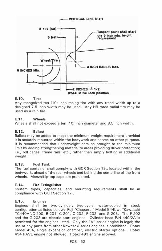
FCS - 62
E.10. TiresAny recognized ten (10) inch racing tire with any tread width up to a designed 7.5 inch width may be used. Any HR rated radial tire may be used as a rain tire.
E.11. WheelsWheels shall not exceed a ten (10) inch diameter and 8.5 inch width.
E.12. BallastBallast may be added to meet the minimum weight requirement provided it is securely mounted within the bodywork and serves no other purpose. It is recommended that underweight cars be brought to the minimum limit by adding strengthening material to areas providing driver protection; i.e., roll cages, frame rails, etc., rather than simply bolting in additional weight.
E.13. Fuel TankThe fuel container shall comply with GCR Section 19., located within the bodywork, ahead of the rear wheels and behind the centerline of the front wheels. Monza/flip-top caps are prohibited.
E.14. Fire ExtinguisherSystem types, capacities, and mounting requirements shall be in compliance with GCR Section 17..
E.15. EnginesEngines shall be two-cylinder, two-cycle, water-cooled in stock configuration as listed below: Fuji “Chaparral” Model G44bw. “Kawasaki TC440A”/C-200, B-201, C-201, C-202, F-202, and G-203. The F-202 and the G-203 are electric start engines. Cylinder head P/N 440/2A is permitted for the engines listed. Only the “A” series engine is legal; the use of any parts from other Kawasaki series engines is prohibited. Rotax Model 494, single expansion chamber, electric starter optional. Rotax 494 RAVE engine not allowed. Rotax 493 engine allowed.
FCS - 63
AMW engine as specified: The AMW engine approved for F500 shall be the AMW model no. 250-2 RC2, two-cylinder, two cycle, liquid cooled, reed valve engine with a nominal bore and stroke of 72mm x 61mm and a displacement of 497cc. All components of the engine shall be in “as cast” condition or as delivered from AMW. No component of the engine may be altered, modified, or changed nor be of any other origin than the original equipment manufacturer (OEM) unless specifically authorized in these rules. Any Y-pipe exhaust manifold and single expansion chamber meeting 12.1.6.E.15.b is permitted. All factory technical bulletins shall be approved by the Club Racing Board prior to implementation and publication. AMW Technical Bulletins #10/96.01, Published October 1996, #03/97.01, Published January 1997 and Technical Bulletin #04/99.01, Published February 1999, have been approved by the Club Racing Board.
Hardware items (nuts, bolts, etc.) may be replaced with similar items performing the same fastening function(s).
No component of approved engines may be altered, modified, or changed, nor be of any other than original equipment manufacture unless specifically authorized. Engine components shall be assembled in stock configuration. Stock configuration is defined as including: thermostat, water outlet elbow, ignition harness, etc.
Authorized Changes:a. Carburetors: The induction system is restricted to two (2)
38mm Mikuni VM 38 round slide carburetors (except AMW). No modifications are permitted to the carburetor bodies. The use of any jets or jet needles is permitted.
Carburetor mounting shall be of individual runners, no balance pipes, no plenums. Restrictor plates are no longer required. Supercharging, turbocharging, and direct fuel injection are prohibited. If balance tube(s) are in place from the manufacturer they must be removed and the openings must be plugged.
b. Any exhaust pipe(s) may be used (unless otherwise specified), provided they meet a sound limit of 92db on the “A” scale measured fifty (50) feet behind the vehicle, with engine running at a steady 4,000 RPM, without load. Maximum exhaust length behind the rear axle centerline is twenty-four (24) inches. It is the intent of this rule that the exhaust pipe includes the exhaust manifold.
c. Alternate piston replacement for Chaparral engine only, “Wiseco” one-ring piston.
d. Any thermostat may be used.
e. Alternate AMW/Wiseco piston (#2687) is permitted.
f. Engine specifications will not be changed during the current year.
FCS - 64
g. Rotax 494 engines: Any Rotax 494 model thermostat housing or water outlet elbow may be used. The water bypass may be blocked.
h. Rotax 494 engine only: Rotax OEM 0.010” overbore piston P/N 887-554 is permitted. Engines may be overbored as specified by Rotax so that this piston may be fitted.
i. Alternate WISECO piston (#2084PS) is permitted (for Kawasaki engine only).
j. Rotax 493 engine only: Rotax OEM 0.010” overbore piston P/N 420888443 is permitted. Engines may be overbored as specified by Rotax so that this piston may be fitted.
E.16. Chain/Belt GuardsProtective guards made from 1/8” aluminum or 3/32” steel are required where belt or chain breakage could result in injury to the driver or damage to items necessary for the safe operation of the vehicle. This includes, but is not limited to, fuel lines, fuel tanks, brake lines, radiator, and water hoses.
E.17. RadiatorCapacity, size, shape, location, and number are unrestricted. Overhead radiators shall be at least six (6) inches rearward of driver’s head.
E.18. Safety ItemsIn addition to previously mentioned items, the following equipment is required. Vehicle will be fitted with:
a. A firewall which effectively protects the driver. (Refer to GCR Section 19.1)
b. A complete driver restraint system including shoulder straps, lap belt, and submarine strap(s). (Refer to GCR Section 20.)
c. Mirrors affording the driver clear fields of vision behind him/her, and on both sides of the car.
d. Cars shall not be started with rear wheels on the ground unless a driver is on board.
F.1. FORMULA MAZDAa. EligibilityOnly cars homologated as Formula Mazda are eligible for competition in this class.
b. Formula Mazda DescriptionFormula Mazda cars are one design, single seat, open wheel automobiles conforming to safety standards as per regulations. Engine - Mazda 13B rotary as approved by SCCA Club Racing.
c. The Intent of the RulesAll components of the car shall be purchased from Star Race Cars, sourced
FCS - 65
from the supplying manufacturer to Star Race Cars or fabricated as exact replicas of components supplied by Star Race Cars. It is the explicit intention of these rules and regulations to prohibit innovation and alteration of the cars except as provided by these regulations or supplements.
d. Additional Safety Requirements, Decals, and PatchesA firewall, full width between the roll bar upright, securely attached at the level of the shoulder harness attachment bolts, up to and bolted to the upper headrest cross member, is mandatory. The manufacturer’s new rollover bar design (February 2000) for the Star Race Car FM chassis is accepted. All Star Race Cars Formula Mazda chassis shall be converted to the manufacturer’s new rollover bar design by 1/1/2001.
e. Vehicle Preparation1. Electrical
A. Alternators (P/N 3A2T4167 Mitsubishi 65 Amp or P/NA5T41474 Mitsubishi 60 Amp) shall be in working order and not modified in any manner. Belt tension shall be within the factory tolerance.
B. Battery shall be securely mounted in front of the master cylinders, in the center nose support frame. Battery type is unrestricted.
C. The wiring harness may be modified so long as it does not change the actual electrical function of the car and does not override the alternator or rev limiter.
D. The use of the MSD (P/N 6446 only) 6T spark box, MSD Soft Touch limiter, or MSD (P/N 6420 - 6AL) is mandatory. Location of the spark box and limiter is unrestricted, provided that access to visually inspect and remove the limiter chip is not impeded. A 6600 rpm limiter chip is standard. A maximum rpm of 6850rpm is allowed. Competitors may use adjustable rev chip (MSD part # 080-135). Competitors are advised that MSD chip function may vary with temperature, and should take measures to ensure compliance at all times.
E. Instrumentation is unrestricted
F. Bosch Blue coil is mandatory.
G. MSD Spark Plug wires (Part #31919) are mandatory.
2. Radiators and PlumbingA. Fluidyne oil cooler # DB30130 or any brand oil cooler
measuring (+/- 1/2”) 2” thick x 12” wide x 12 1/4” high shall be fitted behind the engine in front of the wing, above the gearbox.
B. Water radiators shall be fitted in both sidepods. They shall be installed in series with each other. The swirl pot shall be connected to the inboard inlet of the left

FCS - 66
radiator. The outboard outlet of the left radiator shall be connected to the right side radiator’s outboard inlet. Approved radiators: Volkswagen P/N 171121253D. STAR RACE CARS P/N 100-101 and STAR RACE CARS P/N 100-142.
C. All cars shall be equipped with oil and coolant catch tanks per GCR Section 17.
D. Flat sheet metal blanking material may be fitted surrounding the radiators and oil cooler to prevent cooling air from leaking around the radiators or oil cooler rather than passing through. Synthetic foam sealing material may also be used for this purpose, provided that any combination of materials do not extend more than 3” beyond the plane of the radiator or cooler, and may not extend outside the standard bodywork.
3. EngineA. The spec engine shall be the six (6) port Mazda 13B
Rotary (eligible for Regional and National competition) or the four (4) port Mazda Renesis Rotary in regional competition only, as approved by SCCA Inc. Said engine is to be sealed by an approved engine builder and shall remain so with no modifications to the engine or any of its accessories or components.
All engines shall be returned to an SCCA approved engine builder to be dynoed and resealed with the new generation engine seals by the following dates:
National Competitors: September 1, 2003 Regional Competitors: January 1, 2005
B. No engine may be rebuilt except by a rebuilder approved by SCCA Club Racing.
Approved Engine Builders:1. Daryl Drummond Enterprises, Inc. 3590 North River Rd Gold Hill OR 97525 mailing address: PO Box 678 Rogue River OR 97537 (541) 582-1786
C. The use of any impregnating material in the engine is expressly prohibited.
D. Engine drain plugs shall be safety wired.
E. Alternate Header (13B) STAR RACE CARS P/N 050-133 or Star Race Cars system provided with Renesis conversion kit is permitted.
FCS - 67
F. Minimum flywheel weight - 8.5 lbs.
G. Alternate one-piece intake manifold (part # 050-142) is permitted. If the Renesis motor is used, the standard, unmodified factory fuel injection must be used.
H. Spark plugs are unrestricted
I. Ceramic apex seals, Mazda part number 0000-01-9115, may be used.
4. Fuel SystemA. All carburetor jets are unrestricted, but no other
modifications shall be made to the carburetor (50mm DCO/sp or 48mm DCO modified to 50mm, as supplied). Chokes 44mm. F.15 emulsion tubes are required.
B. Only the standard Weber 48 DCOE intake horns are permitted.
C. Fuel pump, fuel filter(s), fuel pressure regulator are unrestricted. Fuel lines shall be –6 metal braided hose, otherwise unrestricted.
D. Only the factory fuel injection can be used with the Renesis motor (no carburetor).
5. DrivetrainA. Limited slip differentials, torque biasing devices, locking
differentials or full locked differentials are prohibited. Aluminum or modification of the unit provided is prohibited.
B. 10:31, ring and pinion.
C. The use of any impregnating material in the drivetrain is expressly prohibited. REM Isotropic© or REM type treatments are not allowed.
6. Weight and DimensionsA. Maximum wheelbase - 94-5/8”
B. Maximum track front - 59-1/4”
C. Maximum track rear - 57-3/4”
D. Minimum weight with driver = 1350 lbs w/ 6 port 13B, 1400 lbs w/ 4 port Renesis.
E. Ballasting is permitted. Ballast shall be mounted forward of the fuel cell but aft of the instrument panel bulkhead and/or aft of the nose pole but ahead of the master cylinder bulkhead. Ballast shall be mounted securely.
FCS - 68
7. SuspensionA. Ride height is unrestricted within the standard adjustment
range. Droop limiters are not allowed.
B. Anti-roll bar stiffness may be adjusted within the range allowed by sliding clamps on the anti-roll bar or front bars may be drilled for adjustment. Anti-roll bars may be disconnected.
C. 5/8 or 11/16 inch front and 11/16 or 3/4 inch rear anti-roll bars (solid) are required.
D. Shock absorber settings are unrestricted, but no alteration to the internal mechanism or fluid medium is allowed. Extended top shock spring retainers may be used to ensure clearance from suspension members, or to prevent spring disengagement at full droop.
E. Shock absorber - front: Koni P/N 82x-2236, rear: 82x-2269. Alternates: front: 8216-2420, rear: 8216-2421, or front: 3012-1604FMF, rear: 3012-1616FMR. Spring rates are unchanged. Shock absorber sealastic – 55mm P/N 000-141 (Koni P/N 70-34-53-000-0) or 40mm P/N 000-146 (Koni P/N 70-34-54-000-0). Shock absorber packer(s) P/N 000-147 (Koni P/N 15-34-62-000-0). The number of packers is unrestricted. Sealastics and packers shall be unmodified except that the standard slit may be widened or made into a wedge shape to facilitate installation and removal. When Koni shock absorbers 3012-1604FMF and/or 3012-1616FMR are used, the Koni shock bumpers P/N 000-152, Koni P/N 71-34-48-000-0 may also be used.
F. Springs: Front: six (6) or seven (7) inch unrestricted length, 450, or 750 lbs./inch rate. Rear: eight (8) inch unrestricted length, 400 or 500 lbs/inch rate.
G. Camber, caster, toe-in/out, bump steer, are unrestricted within the adjustment range provided on the car.
H. Manufacturer and construction of spherical bearings and rod ends are unrestricted; however, geometry and length cannot be changed.
8. WingsA. Wing “angle of attack” (front and rear) is unrestricted
within the adjustment range. Rear wing adjuster link (P/N 110-126) length is 2.25” overall. It is permitted to shorten existing rear wing adjuster links to 2.25” overall length to match revised part (P/N 110-126).
B. Wings may be of aluminum construction, but shall conform to stock dimensions as described by the manufacturer.
FCS - 69
C. Gurney flaps for wings (3/4” Front max. & 3/8” Rear max.) are permitted, provided they are mounted on the upper surface of the wing). Note: Gurney flaps are measured from the upper wing surface, normal to the surface and must not serve to increase the plane of the wing. (Quick change attachment is prohibited, bolted or riveted only)
9. BrakesA. Tilton brakes bias adjustment may be fitted.
B. Brake master cylinder - Use of (any) 3/4” or 5/8” master cylinders (with individual reservoir) is approved.
C. Any mass produced brake pad that fits the standard caliper without modification is permitted.
D. Modification of brake rotor is prohibited. Option: Two piece brake rotor, STAR RACE CARS P/N 040-126 and STAR RACE CARS P/N 040-127 may be used. Minimum brake rotor thickness = 0.300”.
E. Optional brake caliper STAR RACE CARS P/N 040-130 may be substituted.
F. The use of any ferrous brake caliper piston is permitted.
10. Tires and WheelsA. A competitor shall start the race on the same set of tires
(meaning the original four) used in the qualifying session. It is the responsibility of the competitor to ensure their tires are marked appropriately for the qualifying and race sessions. It is recommended that regions offer these services at a central location and at a standardized time, preferably at Tech.
B. Any change of tires during or between a qualifying session shall automatically result in all previous times being disallowed.
C. If a tire is damaged during a qualifying session, the competitor may replace that tire with a used tire upon approval by the Chief Steward. Should a tire be replaced for any reason, the competitor shall forfeit his grid position and start at the back of the grid.
D. Rain tires may be used at any time.
E. Any competitors deemed to have taken steps to circumvent these rules, or deemed to have used a foreign substance on the tire in order to gain an advantage shall be immediately disqualified from that event.
FCS - 70
F. All cars shall run BBS (8” x 13”) front and (10” x 13”) rear wheels as specified by the manufacturer. Alternate BBS wheel center (part # 000-143 & 000-154) is permitted.
G. Use of tire warmers or cooling methods other than natural air convection or conduction is prohibited.
11. GearboxA. All cars shall be equipped with some combination of the
following gears:
Mark5, or Mark8 Series Gears 15:36 – 15:30 – 15:25 – 17:34 – 19:32 – 18:25 – 21:29 – 17:23 – 22:30 – 24:27 – 19:23 – 23:28 – 25:26 – 26:25 – or 26:26 Webster; 24:24 Hewland
B. Additional approved gear ratios may be added by the manufacturer with SCCA Club Racing authorization.
C. Reverse shall be installed and in workable condition.
D. Gearbox rear covers may be modified to permit installation of longer shift finger shafts.
E. Transmission drain plugs shall be safety wired.
F. Shift rail stops may be added to transmission shift mechanism.
12. ClutchA. Only 1700 pound KEP or 2300 pound KEP pressure
plate permitted.
B. Clutch disc may be a “Dalkin” or “Marchal” or L&T disc remanufactured on VW core with organic friction material. STAR RACE CARS P/N 060-103
C. Minimum flywheel weight - 8.5 pounds. STAR RACE CARS P/N 060-102
13. MufflersA. All cars shall be equipped with a SuperTrapp muffler P/N
5AS-2556 with twelve (12) plates installed. Twelve (12) plate stack not to exceed 35mm or 1-3/8” from mount to lid, inclusive. Plates shall not be loose regardless of dimension.
B. No matching of the plates, washer, or spacer insertion, or other modification will be allowed.
C. The main muffler, Power Pulse Muffler (Racing Beat) P/N 16400, shall be in good working order with no removal
FCS - 71
of steel wool or other alternations allowed.
D. The following options are allowed:1. Use of the approved “Lo-back” muffler as a
substitute for the Racing Beat muffler. Alternate Muffler STAR RACE CARS P/N 050-134 and header STAR RACE CARS P/N 050-133, are permitted. All other specifications to remain the same.
2. Use of deflectors such as the SuperTrapp mud ring as long as the twelve (12) plates do not exceed the specified height and exhaust gases are only affected after passing through the SuperTrapp plates.
3. Use of fewer than twelve (12) with a proportionate reduction of the specified height of the plate stack.
14. Headers Headers must be unmodified except that high-
temperature coatings are permitted.
15. Hardware and FluidsA. Fasteners, links, and rod ends may be either metric or
standard threads, but shall be at least grade five (5). Hardware and fasteners may not be modified to change adjustment parameters.
B. Brake fluid, fasteners, clamps, and radiator hoses are unrestricted.
C. Lubricants and fluids, except fuel, are unrestricted.
16. CockpitA. Cockpit controls and mechanisms may be adjusted
within their stock operating range.
B. It is permissible to modify the driver’s seat. The driver’s seat attachment bracket on the chassis may be modified to facilitate adjustment, but shall ensure positive retention of seat attachment bolts. Seat shell may be removed and the assembly replaced by a poured foam seat.
C. The head rest may be extended forward to improve head support, provided the spacer(s) and attachments serve no other purpose.
D. A quick disconnect steering wheel may be used. Make and diameter are unrestricted.
E. A fabricated sheet aluminum cockpit liner is permitted.
17. BodyworkA. Engine covers are required. Air inlet ducts may be trimmed
FCS - 72
but must not change profile of outside bodywork.
B. Mirrors are California by Vitaloni - Model #01CBT. Alternate rear view mirror (P/N 110-136) is permitted.
C. No modification to body external contour or dimensions is permitted. No openings may be added or reshaped. A blister may be added to the engine cover if needed for clearance between carburetor linkage and bodywork. Optional: rearmost, rear face of sidepods may be open, closed, or vented by drilling.
D. The aluminum undertray may be replaced with a stress-bearing undertray, minimum of eighteen (18) gauge steel. This undertray shall be attached to the frame by welding, bonding, or by rivets or threaded fasteners.
E. Star Formula Mazda bodywork or exact equivalent is required.
F. A windscreen may be added to the bodywork, it shall: 1) Not exceed 144 square inches of surface, nor stand more than six inches normal (measured 90 degrees to the surface) to the bodywork. 2) Be constructed from flat stock with no compound curves. 3) Be symmetrical left to right. 4) Not extend more than 12 inches to each side from the car’s longitudinal centerline, measured along the cockpit opening. 5) Not constitute a potential hazard to driver, emergency crews or other competitors.
G. Engine compartment belly pan, STAR RACE CARS P/N 030-132, or any sheet metal pan covering the underside of the engine compartment, provided it is flat when viewed from the bottom (may have a bend up at the leading edge for stiffness), and does not extend past the trailing edge of the frame, nor more than 1.5” past the outer edges of the frame on each side.
G.1 Formula S Class (FS) (Regional Class Only):A. DefinitionA formula for purpose built, highly modified single-seat, open-wheel, open cockpit racing cars, which meet the general regulations of Section 17 of the GCR for Formula Category cars, yet are different in concept and specifications from the current SCCA Formula classes. Homologation is required on ALL Formula S cars.
All Formula S cars registered after January 1, 2003 shall meet all preparation rules of Section G.1. Formula S cars registered prior to January 1, 2003 may be updated to Section G.1. specifications but they shall meet all requirements of Section G.1. without exception.
Exceptions to the FS specifications must be requested with the homologation application and will be listed on the homologation certificate.
FCS - 73
B. Chassis/FrameChassis/frame construction is unrestricted within the following limitations:
1. Chassis of non-metallic composite construction shall be proven to meet FIA specifications for non-metallic composite chassis prior to being submitted to the SCCA for homologation. There are no exceptions. Contact SCCA National Office for a list of the relevant FIA specifications/SCCA requirements.
2. Chassis of metallic tube and/or metallic monocoque construction shall be manufactured to be consistent with the safety requirements outlined within these rules and the GCR.
C. EnginesAny engine(s) may be used within the following limitations:
1. Piston or rotary internal combustion, gasoline-fueled engines only. No turbines. Turbo and/or supercharging is permitted.
D. Fuel SystemFuel system is unrestricted within the following limitations:
1. Fuel per GCR Section 17.4
2. Fuel Cell Vents: Fuel tank air vents shall be located at least 25cm (9.843 inches) to the rear of the cockpit.
3. Fuel Filler Neck: Fuel filler necks, caps, or lids shall not protrude beyond the bodywork of the car.
E. Electrical SystemElectrical system is unrestricted within the following limitations:
1. Self Starter: Cars shall be equipped with on-board self-starter and on-board power supply controlled by the driver while in a normal driving position.
2. Lights - Brake and Tail per GCR Section 17.19
F. Transmission / Final DriveTransmission / final drive system is unrestricted within the following limitations:
1. Power shall not be applied to more than two (2) wheels.
G. Bodywork and AirfoilsBodywork and airfoils are unrestricted within the following limitations:
1. Firewall and floor per GCR Section 17.21
2. Driver Visibility per GCR Section 17.29
3. Cockpit Opening: The driver’s seat shall be capable of being entered without
the removal or manipulation of any part or panel (except for a removable steering wheel and removable cockpit padding).
The cockpit opening of metallic chassis shall have the following
FCS - 74
minimal dimensions:
Length: 60cm (23.622 inches) Width: 45cm (17.717 inches)
This width extends over a length of 30cm (11.811 inches) minimum. This minimal rectangular opening may exist anywhere forward of the bracing, and required padding will not be considered in these dimensions.
The cockpit opening of non-metallic chassis shall be designed to meet the FIA F3 homologation requirements (article 275).
4. Aerodynamic Devices:a. The mounting apparatus of any part having an aerodynamic
influence (i.e. bodywork, floor, sidepods, wings, spoilers, etc.), shall be rigidly secured to the entirely sprung part of the car (chassis/monocoque), shall have no degree of freedom in relation to the entirely sprung part of the car (chassis/monocoque), and shall remain immobile in relation to the chassis/monocoque at all times. This allows for actively adjusted aerodynamic elements (i.e. wings, diffusers, etc.).
b. No Aerodynamic skirts per GCR Section 17.14. Within the preceding restrictions, only wearable material (fiberglass, Kevlar, carbon fiber, high density polyethylene, polypropylene, Teflon, Lexan, or wood) may be attached to the side panels as a rubbing strip. Ceramics, brittle plastics (i.e. Plexiglas), and other materials which shatter or break-up causing hazardous track conditions are prohibited.
c. Ground effects are permitted, but may not be attained by “sealing” or bridging the gap between the bodywork and the road surface. Any means adopted to circumvent this intention shall automatically be regarded as a breach of these regulations.
d. Leading Edges of Airfoils: The leading edge of any airfoil fixed to the front of the car shall not be sharp. Minimum radius: 1.5cm (0.06 inches).
H. SuspensionSuspension is unrestricted within the following limitations:
1. All cars shall be equipped with a full suspension system (i.e. springs, torsion bars, etc.) front and rear. Rigid mounted suspensions are prohibited. Monoshock/monospring systems are permitted.
I. Steering1. Unrestricted provided that it is of a safe/secure design and acts
upon at least two wheels at one end of the vehicle.
J. Wheels and TiresWheels and tires are unrestricted within the following limitations:
FCS - 75
1. Tires shall have a minimum speed rating of 120 mph or better. Tires shall be the same size and design (i.e. radial, bias-ply, etc.) for the right and left sides of the front axle(s), and same size and design (i.e. radial, bias-ply, etc.) for the right and left sides of the rear axle(s).
2. Wheels: Minimum diameter 10”, minimum width 5.5”. Wheels shall be identical for the right and left sides of the front axle(s), and identical for the right and left sides of the rear axle(s). Wheel material shall be metal. Cars shall be equipped with a minimum of four (4) wheels. Wire wheels are prohibited.
K. BrakesBrakes are unrestricted within the following limitations:
1. Cars shall have a braking system that acts upon all wheels of the vehicle. Chain/belt driven cars may have a single brake caliper that acts upon the differential, thereby applying braking force to the two (2) drive wheels.
2. Cars shall be equipped with a dual braking system operated by a single control. In case of failure or leak at any point in the system, effective braking power shall be maintained on at least two wheels.
L. Weight (without driver)1. The minimum weight of the vehicle as raced, without driver,
shall be 750 lbs. Cars of composite (i.e. fiberglass, carbon fiber, Kevlar, etc.) chassis construction shall not exceed a maximum weight, as raced without driver, of 1300 lbs. Cars of conventional tubular space-frame or metallic monocoque chassis construction that are in excess of 1500 lbs, as raced without driver, require specific approval by the Club Racing Board and the Club Racing Technical Manager for homologation and competition eligibility.
M. Safety EquipmentNote: All FS cars must meet all applicable portions of GCR Sections 17, 18, 19 & 20.
1. Fuel Cells per GCR Section 19.
2. Fire System per GCR Section 17.22.
3. Scattershields & Chain/Belt Guards per GCR Section 17.24.
4. Oil Catch Tanks, Filters And Breathers per GCR Section 17.26.
5. Master Switch per GCR Section 17.27.
6. Mirrors per GCR Section 11.2.1.R. Additionally, there shall be at least two (2) mirrors, each with a minimum 55cm² (8.53 in²) of reflective surface.
7. Towing Eyes per GCR Section 17.31. Additionally, if the rollbar is faired-in, the fairing shall have rollbar access hole(s) to allow for quick retrieval.
FCS - 76
8. Fuel and Oil Lines per GCR Section 17.34.
9. Roll Cage per GCR Section 18.1. & 18.5.
10. Side Intrusion Protection For metallic chassis, the area between the upper and lower main
frame tubes from the front roll hoop bulkhead to the rear roll hoop bulkhead shall be protected by one of the following methods to prevent the intrusion of objects into the cockpit.
a. Panel(s), minimum of either .060” heat-treated aluminum (6061-T6 or equivalent) or eighteen (18) gauge steel, attached outside of the main frame tubes.
b. Reinforced body - at minimum, consisting of a double layer, five (5) oz., bi-directional, laminated Kevlar material incorporated into the body which shall be securely fastened to the frame.
c. For either method, the material used for the chassis braces in this area shall be at least equivalent to the roll hoop brace material.
d. Non-metallic chassis are covered under the FIA chassis homologation.
11. Crushable Structure For metallic chassis there shall be a crushable structure, securely
attached to the front bulkhead, with a minimum cross section of 200 cm² (31 in²), 40cm (15.75”) forward of the clutch and brake pedals (not depressed) constructed of a minimum of eighteen (18) gauge 6061-T4 or equivalent aluminum.
a. Radiators may be incorporated in this structure.
b. Non-metallic chassis are covered under the FIA chassis homologation.
12. Driver’s Feet Position For metallic chassis, the frame shall incorporate forward-facing
braces to protect the driver’s legs and feet. The braces shall extend from the front roll hoop to the front bulkhead. (The front bulkhead is defined as the furthest forward transverse section of the main frame.) The soles of the driver’s feet shall not extend beyond the front edge of the wheel rims (in normal position; i.e., pedals not depressed) and shall remain behind the front bulkhead. The lower main frame rails shall be a minimum of twenty-five (25) centimeters (9.84”) apart (inside dimension) from the front bulkhead to the rear roll hoop.
a. Non-metallic chassis are covered under the FIA chassis homologation.

NOTES:

NOTES:

NOTES:

CLUB RACING
An electronic copy of the 2006 General Competition Rules is available on the SCCA website www.scca.com
Sports Car Club of America, Inc.Club Racing Department
Building 300 B StreetTopeka, Kansas 66619


![Homologation paper list- Manufacturers[7]](https://img.pdfslide.net/doc/110x75/58944f3b1a28ab40618b6736/homologation-paper-list-manufacturers7.jpg)