Embed Size (px)
Citation preview

INTRODUCTION
- How to Use This Manual
This manual is divided into multiple sections, The first page of each section is marked with a black tab that lines up with its corresponding thumb index tab on this page and the back cover. You can quickly find the first page of each section without looking through a full table of contents. The symbols printed at the top corner of each page can also be used as a quick reference system. Each section includes;
1. A table of contents, or an exploded view index showing; • Parts disassembly sequence. • Bolt torques and thread sizes. • Page references to descriptions in text.
2. Disassembly/assembly procedures and tools. 3. Inspection. 4. Testing/troubleshooting. 5. Repair. 6. Adjustments.
- Safety Messages ^ ^
Your safety, and the safety of others, is very important. To help you make informed decisions, we have provided safety messages, and other safety information throughout this manual. Of course, it is not practical or possible to warn you about all the hazards associated with servicing this vehicle. You must use your own good judgment. You will find important safety information in a variety of forms including: 9 Safety Labels — on the vehicle. • Safety Messages — preceded by a safety alert symbol and
one of three signal words, DANGER, WARNING, or CAUTION. These signal words mean:
' " t : 2 M ? S i 3 Y o u WILL be KILLED or SERIOUSLY HURT if you don't follow instructions.
L^MS?i^^3 You CAN be KILLED or SERIOUSLY HURT if • you don't follow instructions.
l / l \ @ ^ i 5 n | You CAN be HURT if you don't follow instructions.
0 Instructions — how to service this vehicle correctly and safely.
General Information
Specifications
Maintenance
*Engine Electrical
Engine Mechanical
Engine Cooling
Fuel and Emissions
*Transaxle
All information contained in this manual is based on the latest product information available at the time of printing. We reserve the right to make changes at anytime without notice. No part of this publication may be reproduced, or stored in a retrieval system, or transmitted, in any form by any means, electronic, mechanical, photocopying, recording, or otherwise, without the prior written permission of the publisher. This includes text, figures, and tables.
As you read this manual, you will find information that is preceded by a | NOT ICE] symbol. The purpose of this message is to help prevent damage to your vehicle, other property, or the environment.
First Edition All Rights Reserved Specifications apply to USA and Canada
HONDA MOTOR CO., LTD. Service Publication Office
As sections with * include SRS components; special precautions are required when servicing.
marked sections are not included in this manual, see Volume 2.
2008-10 Accord Vol. 1

SUPPLEMENTAL RESTRAINT SYSTEM (SRS)
The Accord SRS Includes a driver's airbag in the steering wheel hub, a passenger's airbag In the dashboard above the glove box, seat belt tensioners in the front seat belt retractors, side curtain airbags in the sides of the roof, and side airbags in the front seat-backs. Information necessary to safely service the S R S is included in this Service Manual. Items marked with an asterisk (*) on the contents page include or are located near SRS components. Servicing, disassembling, or replacing these items requires special precautions and tools, and should be done by an authorized Honda dealer.
• To avoid rendering the SRS inoperative, which could lead to personal injury or death in the event of a severe frontal or side collision, all SRS service work should be done by an authorized Honda dealer.
• Improper service procedures, including incorrect removal and installation of the S R S , could lead to personal injury caused by unintentional deployment of the airbags, side airbags, and/or side curtain airbags.
• Do not bump or impact the SRS unit, front impact sensors, side impact sensors, or rear safing sensor, especially when the ignition switch is in ON (II), or for at least 3 minutes after the ignition switch is turned to LOCK (0); otherwise, the system may fail in a collision, or the airbags may deploy.
• SRS electrical connectors are identified by yellow color coding. Related components are located in the steering column, center console, dashboard, dashboard lower cover, in the dashboard above the glove box, in the front seats, in the roof side, and around the floor. Do not use electrical test equipment on these circuits.

General Information
General Information Chassis and Paint Codes
'08 4-door Model 1-2 '08 2-door Model 1-3 '09 4-door Model . 1-4 '09 2-door Model . . 1-5 ' 10 4-door Model 1-6 '10 2-door Model 1-7
Identification Number Locations 1-8 Danger/Warning/Caution Label Locations 1-9 Under-hood Emission Control Labe l . . . . . . 1 -12 Lift and Support Points 1-13 Towing 1-14 Parts Marking 1-16

General Information
Chassis and Paint Codes - '08 4-door Model
Vehicle Identification Number
1HGCP2 5 3 * 8 A 000001 rrrrrrri a b c d e f g h
a. Manufacturer, Make, and Type of Vehicle 1HG: Honda of America Mfg., Inc.
Honda passenger vehicle JHM: Honda Motor Co., Ltd.
Honda passenger vehicle b. Line, Body, and Engine Type
CP2: Accord/K24Z2, K24Z3 c. Body Type and Transmission Type
5: 4-door Sedan/5-speed Manual 6: 4-door Sedan/5-speed Automatic
d. Vehicle Grade (Series) USA models Canada models 3: LX, LX PZEV 3: LX 4: LX-P, LX-P PZEV 4: LX-P 7: EX, EX PZEV 7: EX 8: EX-L, EX-L PZEV 8: EX-L
e. Check Digit f. Model Year
8: '08 g. Factory Code
A: Marysville, Ohio Factory in U S.A. C: Saitama Factory in Japan
h. Serial Number 0 0 0 0 0 1 U S A models 800001 —: Canada models
Vehicle Identification Number, Federal Motor Vehicle Safety Standard Certification, and Paint Code Label. Vehicle Identification Number, Canadian Motor Vehicle Safety Standard Certification, and Paint Code Label.
PAINT CODE INTERIOR COLOR CODE
Engine Number
K24Z2 - 1000001
a
a. Engine Type K24Z2: 2.4 L DOHC i-VTEC Sequential Multiport
Fuel-injected, 177HP engine K24Z3: 2.4 L DOHC i-VTEC Sequential Multiport
Fuel-injected, 190HP engine b. Serial Number
1000001 —: All models except PZEV produced in Marysville
1400001 —: All models except PZEV produced in Saitama
1500001 - : PZEV produced in Marysville 1700001 - : PZEV produced in Saitama
Transmission Number
88E5 - 8000001
a b
Transmission Type 88E5: 5-speed Manual M91 A: 5-speed Automatic B90A: 5-speed Automatic Serial Number 1000001-: M91A, B90A 8000001-: 88E5
Paint Code
Code Color USA Canada models models
B-92P Nighthawk Black Pearl O O B-536P Royal Blue Pearl O o G-530M Mystic Green Metallic. o o NH-578 Taffeta White o o NH-603P White Diamond Pearl o o NH-700M Alabaster Silver Metallic o o NH-737M Polished Metal Metallic o o R-530P Basque Red Pearl o o YR-574M Bold Beige Metallic o o NH-731P Crystal Black Pearl o o
1-2

D
Chassis and Paint Codes - '08 2-door Model
Vehicle Identification Number
1HG CS1 1 3 * 8 A 000001
c d e g h
b.
h.
Manufacturer, Make, and Type of Vehicle 1HG: Honda of America Mfg., Inc.
Honda passenger vehicle Line, Body, and Engine Type CS1: Accord Coupe/K24Z3 Body Type and Transmission Type 1: 2-door Coupe/5-speed Manual 2: 2-door Coupe/5-speed Automatic Vehicle Grade (Series) USA models 3: LX, LX PZEV 7: EX, EX PZEV 8: EX-L, EX-L PZEV Check Digit Model Year 8: '08 Factory Code A: Marysville, Ohio Factory in U.S.A Serial Number 000001- : USA models 800001 - : Canada models
Canada models 7: EX 8: EX-L
Vehicle Identification Number, Federal Motor Vehicle Safety Standard Certification, and Paint Code Label.
Vehicle Identification Number, Canadian Motor Vehicle Safety Standard Certification, and Paint Code Label.
PAINT CODE INTERIOR COLOR CODE
Engine Number
K24Z3 - 1000001
a b
a. Engine Type K24Z3: 2.4 L DOHC i-VTEC Sequential Multiport
Fuel-injected, 190HP engine b. Serial Number
1000001-: Except PZEV 1500001-: PZEV
Transmission Number
8000001
a to
a. Transmission Type 88E5: 5-speed Manual B90A: 5-speed Automatic
b. Serial Number 1000001-: B90A 8000001-: 88E5
Paint Code
Code Color USA Canada models models
B-92P Nighthawk Black Pearl O O G-551P Belize Blue Pearl o o NH-578 Taffeta White o o NH-700M Alabaster Silver Metallic o o NH-737M Polished Metal Metallic o o R-94 San Marino R- o o
1 - 3

General Information
Chassis and Paint Codes - '09 4-door Model
Vehicle Identification Number
1HG CP2 5 3 * 9 A 000001 rrrrrrri a b c d e f g h
a. Manufacturer, Make, and Type of Vehicle 1HG: Honda of America Mfg., inc.
Honda passenger vehicle . JHM: Honda Motor Co., Ltd.
Honda passenger vehicle 3. Line, Body, and Engine Type
CP2: Accord/K24Z2, K24Z3 c. Body Type and Transmission Type
5:4-door Sedan/5-speed Manual 6:4-door Sedan/5-speed Automatic
1 Vehicle Grade (Series) USA models 3: LX, LX PZEV 4: LX-P, LX-P PZEV 7: EX, EX PZEV 8: EX-L, EX-L PZEV
e. Check Digit f. Model Year
9: '09 g. Factory Code
A:Marysville, Ohio Factory in U.S.A. C:Saitama Factory in Japan
h. Serial Number 0 0 0 0 0 1 U S A models 800001 - : Canada models
Canada models 3: LX 4: LX-P 7: EX 8: EX-L
Vehicle Identification Number, Federal Motor Vehicle Safety Standard Certification, and Paint Code Label.
Vehicle Identification Number, Canadian Motor Vehicle Safety Standard Certification, and Paint Code Label.
V.I.N •
rz icnrzn
PAINT CODE INTERIOR COLOR CODE
Engine Number
K24Z2 - 2000001
Engine Type K24Z2: 2.4 L DOHC i-VTEC Sequential Multiport
Fuel-injected, 177HP engine K24Z3: 2.4 L DOHC i-VTEC Sequential Multiport
Fuel-injected, 190HP engine Serial Number 2000001 -2400001 -2450001 -2500001 -2700001 -
.2800001 -
K24Z2 produced in Marysville K24Z2 produced in Saitama K24Z3 produced in Saitama PZEV produced in Marysville PZEV produced in Saitama K24Z3 produced in Marysville
Transmission Number
88E5 8200001
a
b.
Transmission Type 88E5: 5-speed Manual M91A: 5-speed Automatic B90A: 5-speed Automatic Serial Number 2 0 0 0 0 0 1 M 9 1 A , B90A 8 2 0 0 0 0 1 8 8 E 5
Paint Code
Code ' Color USA Canada models models
NH-731P Crystal Black Pearl O O B-536P Royal Blue Pearl o o G-530M Mystic Green Metallic o o NH-578 Taffeta White o o NH-603P White Diamond Pearl o o NH-700M Alabaster Silver Metallic o o NH-737M Polished Metal Metallic o o R-530P Basque Red Pearl o o YR-574M Bold Beige Metallic o o
1 - 4

Chassis and Paint Codes - '09 2-door Model
Vehicle Identification Number
1HG CS1 1 3 * 9 A 000001
a b c d e § h
Manufacturer, Make, and Type of Vehicle 1HG; Honda of America Mfg., Inc.
Honda passenger vehicle Line, Body, and Engine Type CS1: Accord Coupe/K24Z3 Body Type and Transmission Type 1: 2-door Coupe/5-speed Manual 2: 2-door Coupe/5-speed Automatic Vehicle Grade (Series) USA models 3: LX, LX PZEV 7: EX, EX PZEV 8: EX-L, EX-L PZEV Check Digit Model Year 9: '09 Factory Code A: Marysville, Ohio Factory in U.S.A. Serial Number 000001-: USA models 800001 —: Canada models
Canada models 3: LX 7: EX 8: EX-L
Vehicle Identification Number, Federal Motor Vehicle Safety Standard Certification, and Paint Code Label.
Vehicle Identification Number, Canadian Motor Vehicle Safety Standard Certification, and Paint Code Label.
PAINT CODE INTERIOR COLOR CODE
Engine Number
K24Z3 - 2800001
a
Engine Type K24Z3: 2.4 L DOHC i-VTEC Sequential Multiport
Fuel-injected, 190HP engine Serial Number 2500001-: PZEV 2800001-: Except PZEV
Transmission Number
88E5 8200001
b
Transmission Type 88E5: 5-speed Manual B90A: 5-speed Automatic Serial Number 2000001-: B90A 8200001-: 88E5
Paint Code
Code Color USA Canada models models
B-551P Belize Blue Pearl O O NH-578 Taffeta White o O NH-700M Alabaster Silver Metallic o o NH-737M Polished Metal Metallic o o R-94 San Marino Red o o
1 - 5

meml Information
Chassis and Paint Codes - '10 4-door Model
Vehicle Identification Number
1HG CP2 E 3 * A A 000001
r r r r r r r i a b c d e f g h
a. Manufacturer, Make, and Type of Vehicle 1HG: Honda of America Mfg., Inc.
Honda passenger vehicle JHM: Honda Motor Co., Ltd.
Honda passenger vehicle b. Line, Body, and Engine Type
CP2: Accord/K24Z2, K24Z3 c. Body Type and Transmission Type
E: 4-door Sedan/5-speed Manual F: 4-door Sedan/5-speed Automatic
d. Vehicle Grade (Series) USA models Canada models 3: LX, LX PZEV 3: LX 4: LX-P, LX-P PZEV 4: LX-P 7: EX, EX PZEV 7: EX 8: EX-L, EX-L PZEV 8: EX-L
e. Check Digit f. Model Year
A: i O g. Factory Code
A: Marysville, Ohio Factory in U.S.A. C: Saitama Factory in Japan
h. Serial Number - 000001-: USA models 800001 —: Canada models
Vehicle Identification Number, Federal Motor Vehicle Safety Standard Certification, and Paint Code Label. Vehicle Identification Number, Canadian Motor Vehicle Safety Standard Certification, and Paint Code Label.
PAINT CODE INTERIOR COLOR CODE
Engine Number
K24Z2 - 3000001
a
Engine Type K24Z2: 2.4 L DOHC i-VTEC Sequential Multiport
Fuel-injected, 177HP engine K24Z3: 2.4 L DOHC i-VTEC Sequential Multiport
Fuel-injected, 190HP engine Serial Number 3000001 -3400001 -3450001 -3500001 -3700001 -3750001~
K24Z2 produced in Marysville K24Z2 produced in Saitama K24Z3 produced in Saitama PZEV produced in Marysville PZEV produced in Saitama K24Z3 produced in Marysville
Transmission Number
88E5 - 8400001
Transmission Type 88E5: 5-speed Manual M91 A: 5-speed Automatic B90A: 5-speed Automatic Serial Number 3000001—. M91A, B90A 8400001-: 88E5
Paint Code
Code Color USA models
Canada models
NH-731P Crystal Black Pearl o o B-536P Royal Blue Pearl o G-530M Mystic Green Metallic o o NH-578 Taffeta White o o NH-700M Alabaster Silver Metallic o o NH-737M Polished Metal Metallic o o R-530P Basque Red Pearl o o YR-574M Bold Beige Metallic o o
1-6

Chassis and Paint Codes - f10 2-door Model
Vehicle Identification Number
11 A 000001
c.
e f g
Manufacturer, Make, and Type of Vehicle 1HG: Honda of America Mfg., Inc.
Honda passenger vehicle Line, Body, and Engine Type CS1: Accord Coupe/K24Z3 Body Type and Transmission Type A: 2-door Coupe/5-speed Manual B: 2-door Coupe/5-speed Automatic
d. Vehicle Grade (Series) USA models 3: LX, LX PZEV, LX-S 7: EX, EX PZEV 8: EX-L, EX-L PZEV Check Digit Model Year A: '10 Factory Code A: Marysville, Ohio Factory in U.S.A. Serial Number 000001-: USA models 800001 —: Canada models
Canada models 3: LX 7: EX 8: EX-L
Vehicle Identification Number, Federal Motor Vehicle Safety Standard Certification, and Paint Code Label.
Vehicle Identification Number, Canadian Motor Vehicle Safety Standard Certification, and Paint Code Label.
• PAINT CODE INTERIOR COLOR CODE
Engine Number
K24Z3 - 3750001
I i I 5
a. Engine Type K24Z3: 2.4 L DOHC i-VTEC Sequential Multiport
Fuel-injected, 190HP engine b. Serial Number
3500001 --: PZEV 3750001 -•: Except PZEV
Transmission Number
88E5 .8400001
a b . Transmission Type
88E5: 5-speed Manual B90A: 5-speed Automatic
>. Serial Number 3000001-: B90A 8400001-: 88E5
Paint Code
Code Color USA Canada models models
B-551P Belize Blue Pearl O O NH-578 Taffeta White O O NH-700M Alabaster Silver Metallic o o NH-731P Crystal Black Pearl o o NH-737M Polished Metal Metallic o o R-94 San Marino Red o o
1 - 7

General Information
Identification Number Locations
1-8

Danger/Warning/Caution Label Locations
4-door Model
Front Passenger's Compartment;
STEERING COLUMN NOTICE MONITOR NOTICE TENSIONER CAUTION
Steering Wheel: Rear Passenger's Compartment:
('08-09 models)
(cont'd)
1-9
General Information
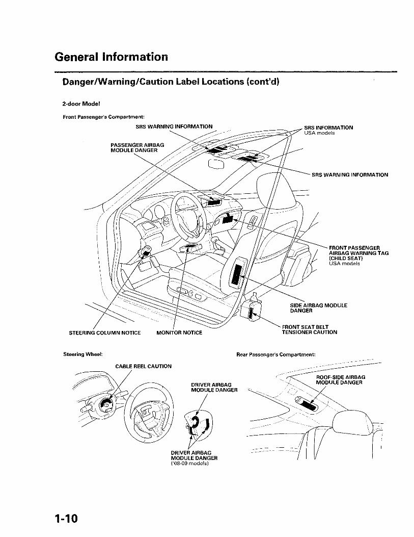
Danger/Warning/Caution Label Locations (cont'd)
2-door Model
Front Passenger's Compartment:
STEERING COLUMN NOTICE ' MONITOR NOTICE TENSIONER CAUTION
Steering Wheel: Rear Passenger's Compartment:
{'08-09 models)
1-10

4-door SV9odel:
S R S WARNING EMISSION CONTROL INFORMATION ('08-09 models) and ENGINE COOLANT INFORMATION
Located on driver's doorjamb
2-door Model:
S R S WARNING EMISSION CONTROL INFORMATION ('08-09 models) and ENGINE COOLANT INFORMATION
Located on driver's doorjamb
1-11
General Information
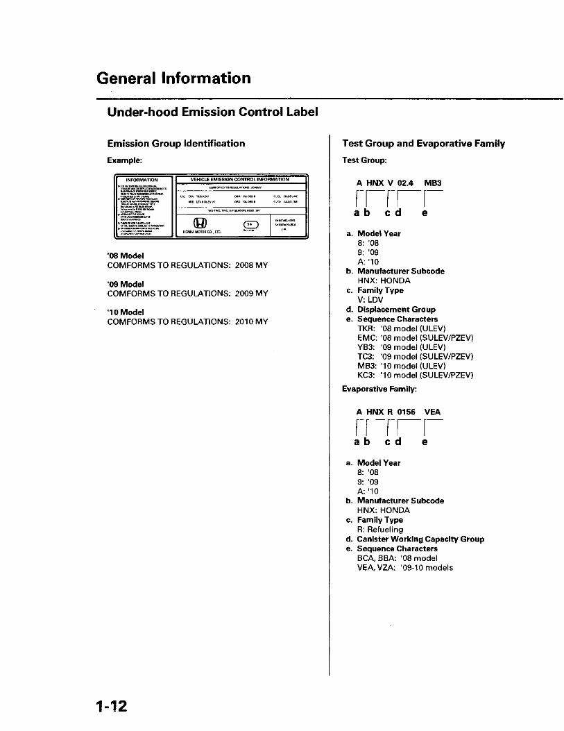
Under-hood Emission Control Label
Emission Group Identification
Example:
INFORMATION MHE FACTOIW W8FAUB IflNCWR
MOUNT mm m mmm ACCOMUM TO
V E H I C L E E M I S S I O N C O N T R O L INFORMATION INFORMATION MHE FACTOIW W8FAUB IflNCWR
MOUNT mm m mmm ACCOMUM TO CONFORMS TO REGULATIONS: 2008MY
m AT tt YEARS WHWKVa OWES BUT. mmmmBimswm. ^<nmmmmmimiamm.cmMir, ummummmicmmvmz
j> CHECK OH ADD TOE COOUOT AT TK HESBtVE TAW, NOT THE MMATOB,
U.S. EPA: T2B5LDV OBO: CAOBDI1 FUEL: GASOLINE ARB: LEVI! ULEV PC OBD: CAOBDII FUEL: GASOLINE
m AT tt YEARS WHWKVa OWES BUT. mmmmBimswm. ^<nmmmmmimiamm.cmMir, ummummmicmmvmz
j> CHECK OH ADD TOE COOUOT AT TK HESBtVE TAW, NOT THE MMATOB,
WU-TWC, TWC, A/F SENSOR, HOZS, SFI
m AT tt YEARS WHWKVa OWES BUT. mmmmBimswm. ^<nmmmmmimiamm.cmMir, ummummmicmmvmz
j> CHECK OH ADD TOE COOUOT AT TK HESBtVE TAW, NOT THE MMATOB, (H) C D
HONDA MOTOR CO., LTD. R 4 0 ' A 0 0
BHNXV02.4TKR CHNJ-R01SCBBA
08 Model COMFORMS TO REGULATIONS: 2008 MY
09 Model
COMFORMS TO REGULATIONS: 2009 MY
'10 Model COMFORMS TO REGULATIONS: 2010 MY
Test Group and Evaporative Family
Test Group:
A HMX V 02.4 MBS
a b c d
a. Model Year 8: '08 9: '09 A: "10
b. Manufacturer Subcode HNX: HONDA
c. Family Type V: LDV
d. Displacement Group e. Sequence Characters
TKR: '08 model (ULEV) EMC: '08 model (SULEV/PZEV) YB3: '09 model (ULEV) TC3: '09 model (SULEV/PZEV) MB3: '10 model (ULEV)
. KC3: '10 model (SULEV/PZEV)
• Evaporative Family:
A HNX R 0156 VEA
a b e d e
a. Model Year 8: '08 9: '09 A: "10
b. Manufacturer Subcode HNX: HONDA
c. Family Type R: Refueling
d. Canister Working Capacity Group e. Sequence Characters
BCA, BBA: '08 model VEA, VZA: '09-10 models
1 - 1 2

Lift and Support Points •
NOTE: If you are going to remove heavy components such as suspension or the fuel tank from the rear of the vehicle, first support the front of the vehicle with tall safety stands. When substantial weight is removed from the rear of the vehicle, the center of gravity can change, causing the vehicle to tip forward on the lift.
Vehicle Lift 1. Position the lift blocks (A) under the vehicle's front
support points (B) and rear support points (C).
2. Raise the lift a few inches, and rock the vehicle gently to be sure it is firmly supported.
3. Raise the lift to its full height, and inspect the vehicle support points for solid contact with the lift blocks.
Safety Stands To support the vehicle on safety stands, use the same support points as for a vehicle lift. Always use safety stands when working on or under any vehicle that is only supported by a jack.
Floor Jack
1. When lifting the front of the vehicle, set the parking brake. When lifting the rear of the vehicle, put the shift lever in reverse for manual transmission, or in the P position for automatic transmission.
2. Block the wheels that are not being lifted.
3. Position the floor jack under the front jacking bracket (A) or the rear jacking bracket (B). Center the jacking bracket on the jack lift platform (C), and jack up the vehicle high enough to fit the safety stands under it.
4. Position the safety stands under the support points, and adjust them so the vehicle is level.
5. Lower the vehicle onto the stands.
1-13

General Information
Towing
If the vehicle needs to be towed, call a professional towing service. Never tow the vehicle behind another vehicle with just a rope or chain It is very dangerous.
Emergency Towing
There are three popular methods of towing a vehicle.
Flat-bed Tow Track Equipment —The operator loads the vehicle on the back of a flat-bed tow truck. This is the best way of transporting the vehicle.
To accommodate the flat-bed tow truck equipment, the vehicle is equipped with front towing hooks (A), front tie down hook slots (B) f a rear towing hook (C), and rear tie down hook slots (D).
The towing hooks can be used with a winch to pull the vehicle onto the flat-bed tow truck, and the tie down hook slots can be used to secure the vehicle to the flat-bed tow truck.
Front:
Rear:
1-14

Wheel Lift Equipment —The tow truck uses two pivoting arms that go under the tires (front or rear) and lifts them off the ground. The other two wheels remain on the ground. This is an acceptable way of towing the vehicle.
Sling-type Equipment —The tow truck uses metal cables with hooks on the ends. These hooks go around parts of the frame or suspension, and the cables lift that end of the vehicle off the ground. The vehicle's suspension and body can be seriously damaged if this method of towing is attempted. This method of towing the vehicle is unacceptable.
If the vehicle cannot be transported by a flat-bed tow truck, it should be towed with the front wheels off the ground. If the vehicle is damaged, and must be towed with the front wheels on the ground, or with all four wheels on the ground, do this:
( N O T I C E • .. • Improper towing preparation will damage the
transmission. Follow the above procedure exactly. If you cannot shift the transmission or start the engine (automatic transmission), the vehicle must be transported on a flat-bed tow truck.
• Trying to lift or tow the vehicle by the bumpers will cause serious damage. The bumpers are not designed to support the vehicle's weight.
Manual Transmission • Release the parking brake. • Shift the transmission in neutral. • Leave the ignition switch in ACCESSORY (I) so the
steering wheel does not lock. • Make sure all accessories are turned off to minimize
battery current draw.
Automatic Transmission • Release the parking brake. • Start the engine. . Shift to D, then to N. • Turn off the engine. . Leave the ignition switch in ACCESSORY (I) so the
steering wheel does not lock. • Make sure all accessories are turned off to minimize
battery current draw.
It is best to tow the vehicle no farther than 50 miles (80 km), and keep the vehicle speed below 35 mph (55 km/h).
1-15

General Information
Parts Marking
To deter vehicle theft, certain major components are marked with the vehicle identification number (VIN). Original parts have self-adhesive labels. Replacement body parts have generic self-adhesive labels. These labels should not be removed. The original engine or transmission VIN plates are not transferable to the replacement engine or transmission.
NOTE; Be careful not to damage the parts marking labels during body repair. Mask the labels before repairing the part.
1-16

Specifications
Standards and Service Limils... .2-2
Design Specifications 2-18 Body Specifications 2-22

Standards and Service Limits
Engine Electrical Item Measurement Qualification Standard or New Serves© Uazlt
Ignition coil Rated voltage 12V Ignition coil Firing order 1 - 3 - 4 - 2
Spark plug Type (All models except PZEV) NGK ILZKR7B-11S Spark plug Type (All models except PZEV) DENSO SXU22HCR11S
Spark plug
Type (PZEV) NGK DILZKR7A11GS
Spark plug
Gap 1.0-1.1 mm (0.039-0.043 in) | -Ignition timing At idle
Check the red mark M/T in neutral, A/Tin N or P
8 ± 2 °BTDC
Drive belt Tension Auto-tensioner Alternator Output At 13.5 V and
normal engine temperature
105 A Alternator
Coil (rotor) resistance At 68 °F (20 °C) 3.4-3.8 Q
Alternator
Slip ring O.D. 14.4 mm (0.57 in) 14.0 mm (0.55 in)
Alternator
Brush length 10.5 mm (0.41 in) 1.5 mm (0.06 in)
Alternator
Brush spring tension 3.24 N (0.33 kgf, 0.73 Ibf) Starter Output 1.6 kW Starter
Commutator mica depth 0.40-0.50 mm (0.016-0.020 in) 0.15 mm (0.006 in) Starter
Commutator runout 0.02 mm (0.001 in) max. 0.05 mm (0.002 in)
Starter
Commutator O.D. 28.0-28.1 mm (1.10-1.11 in) 27.5 mm (1.08 in)
Starter
Brush length 11.1-11.5 mm (0.44-0.45 in) 4.3 mm (0.17 in)
Engine Assembly Item Measurement Qualification Standard or New Service Limit
Compression Pressure (check the engine with the starter cranking)
Minimum _ 932 kPa (9.5 kgf/cm2, 135 psi)
Compression Pressure (check the engine with the starter cranking)
Maximum variation
— 196 kPa (2.0 kgf/c-^?. 28 psi)
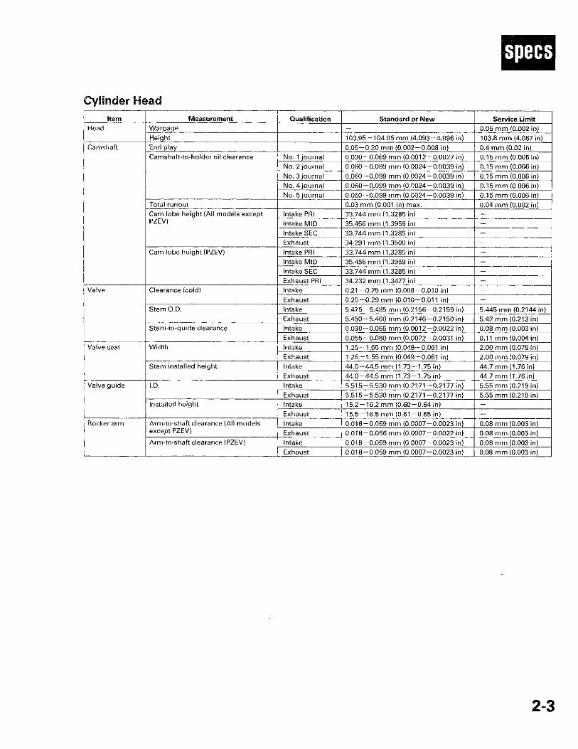
Cylinder Head Item . Measurement Qualification Standard or New Service Limit
Head Warpage - 0.05 mm (0.002 in) Head Height 103.95-104.05 mm (4.093-4.096 in) 103.8 mm (4.087 in)
Camshaft End play 0.05-0.20 mm (0.002-0.008 in) 0.4 mm (0.02 in) Camshaft Camshaft-to-holder oil clearance No. 1 journal 0.030-0.069 mm (0.0012-0.0027 in) 0.15 mm (0.006 in)
Camshaft Camshaft-to-holder oil clearance
No. 2 journal 0.060-0.099 mm (0.0024-0.0039 in) 0.15 mm (0.006 in)
Camshaft Camshaft-to-holder oil clearance
No. 3 journal 0.060-0.099 mm (0.0024-0.0039 in) 0.15 mm (0.006 in)
Camshaft Camshaft-to-holder oil clearance
No. ^journal 0.060-0.099 mm (0.0024-0.0039 in) 0.15 mm (0.006 in)
Camshaft Camshaft-to-holder oil clearance
No. 5 journal 0.060-0.099 mm (0.0024-0.0039 in) 0.15 mm (0.006 in)
Camshaft
Total runout 0.03 mm (0.001 in) max. 0.04 mm (0.002 in)
Camshaft
Cam lobe height (All models except PZEV)
Intake PRI 33.744 mm (1.3285 in) -
Camshaft
Cam lobe height (All models except PZEV) Intake MID 35.456 mm (1.3959 in) -
Camshaft
Cam lobe height (All models except PZEV)
Intake SEC 33.744 mm (1.3285 in) -
Camshaft
Cam lobe height (All models except PZEV)
Exhaust 34.291 mm (1.3500 in) _
Camshaft
Cam lobe height (PZEV) Intake PRI 33.744 mm (1.3285 in) _
Camshaft
Cam lobe height (PZEV) Intake MID 35.456 mm (1.3959 in) _
Camshaft
Cam lobe height (PZEV)
Intake SEC 33.744 mm (1.3285 in) -
Camshaft
Cam lobe height (PZEV)
Exhaust PRI 34.232 mm (1.3477 in) _ Valve Clearance (cold) Intake 0.21 -0 .25 mm (0.008-0.010 in) Valve Clearance (cold)
Exhaust 0.25-0.29 mm (0.010-0.011 in) Valve
Stem O.D. Intake 5.475-5.485 mm (0.2156-0.2159 in) 5.445 mm (0.2144 in)
Valve
Stem O.D. Exhaust r 5.450-5.460 mm (0.2146-0.2150 in) 5.42 mm (0.213 in)
Valve
Stem-to-guide clearance Intake 0.030-0.055 mm (0.0012-0.0022 in) 0.08 mm (0.003 in)
Valve
Stem-to-guide clearance Exhaust 0.055-0.080 mm (0.0022-0.0031 in) 0.11 mm (0.004 in)
Valve seat Width Intake 1.25-1.55 mm (0.049-0.061 in) 2.00 mm (0.079 in) Valve seat Width Exhaust 1.25-1.55 mm (0.049-0.061 in) 2.00 mm (0.079 in)
Valve seat
Stem installed height Intake 44.0-44.5 mm (1.73- 1.75 in) 44.7 mm (1.76 in)
Valve seat
Stem installed height Exhaust 44.0-44.5 mm (1.73-1.75 in) 44.7 mm (1.76 in)
Valve guide I.D. Intake 5.515-5.530 mm (0.2171 -0.2177 in) 5.55 mm (0.219 in) Valve guide I.D. Exhaust 5.515-5.530 mm (0.2171 -0.2177 in) 5.55 mm (0.219 in)
Valve guide
Installed height Intake 15.2-16.2 mm (0.60-0.64 in)
Valve guide
Installed height Exhaust 15.5-16.5 mm (0.61 -0 .65 in) _
Rocker arm Arm-to-shaft clearance (All models except PZEV)
Intake 0.018-0.059 mm (0.0007-0.0023 in) 0.08 mm (0.003 in) Rocker arm Arm-to-shaft clearance (All models except PZEV) Exhaust 0.018-0.056 mm (0.0007-0.0022 in) 0.08 mm (0.003 in)
Rocker arm
Arm-to-shaft clearance (PZEV) Intake 0.018-0.059 mm (0.0007-0.0023 in) 0.08 mm (0.003 in)
Rocker arm
Arm-to-shaft clearance (PZEV) Exhaust 0.018-0.059 mm (0.0007-0.0023 in) 0.08 mm (0.003 in)
2 - 3

Standards and Service Limits
Engine Block Item Measurement Qualification Standard or New Service Limit
Block Warpage of deck 0.07 mm (0.003 in) max. 0.10 mm (0.004 in) Block Bore diameter A or I 87.010-87.020 mm (3.4256-3.4260
in) 87.070 mm (3.4279 in)
Block Bore diameter
B o r l l 87.000-87.010 mm (3.4252-3.4256 in)
87.070 mm (3.4279 in)
Block
Bore taper _ 0.02 mm (0.001 in)
Block
Reboring limit - 0.25 mm (0.010 in) Piston Skirt O.D. at 13 mm (0.5 in) from
bottom of skirt No letter or A 86.980-86.990 mm (3.4244-3.4248
in) 86.930 mm (3.4224 in)
Piston Skirt O.D. at 13 mm (0.5 in) from bottom of skirt
Letter B 86.970-86.980 mm (3.4240-3.4244 in)
86.920 mm (3.4220 in)
Piston
Clearance in cylinder 0.020-0.040 mm (0.0008-0.0016 in) 0.05 mm (0.002 in) Piston ring Ring-to-groove clearance Top 0.060-0.085 mm (0.0024-0.0033 in) 0.13 mm (0.005 in) Piston ring Ring-to-groove clearance
Second 0.040-0.065 mm (0.0016-0.0026 in) 0.13 mm (0.005 in) Piston ring
Ring end gap Top 0.20-0.35 mm (0.008-0.014 in) 0.60 mm (0.024 in)
Piston ring
Ring end gap Second 0.50-0.65 mm (0.020-0.026 in) 0.70 mm (0.028 in)
Piston ring
Ring end gap
Oil 0.20-0.70 mm (0.008-0.028 in) 0.75 mm (0.030 in) Piston pin O.D. 21.961-21.965 mm (0.8646-0.8648
in) 21.953 mm (0.8643 in)
Piston pin
Pin-to-piston clearance -0.005-0.002 mm (-0.0002-0.0001 in) 0.005 mm (0.0002 in) Connecting rod Pin-to-rod clearance 0.005-0.015 mm (0.0002-0.0006 in) 0.02 mm (0.001 in) Connecting rod
Small-end bore diameter 21.970-21.976 mm (0.8650-0.8652 in)
—
Connecting rod
Large-end bore diameter 51.0 mm (2.01 in) _
Connecting rod
End play 0.15-0.35 mm (0.006-0.014 in) 0.40 mm (0.016 in) Crankshaft Main journal diameter No. 1 journal 54.984-55.008 mm (2.1647-2.1657
in) — Crankshaft Main journal diameter
No. 2 journal 54.984-55.008 mm (2.1647-2.1657 in)
—
Crankshaft Main journal diameter
No. 3 journal 54.976-55.000 mm (2.1644-2.1654 in)
— •
Crankshaft Main journal diameter
No. 4 journal 54.984-55.008 mm (2.1647-2.1657 in)
—
Crankshaft Main journal diameter
No. 5 journal 54.984-55.008 mm (2.1647-2.1657 in)
—
Crankshaft
Rod journal diameter 47.976-48.000 mm (1.8888-1.8898 in)
—
Crankshaft
Rod/main journal taper 0.005 mm (0.0002 in) max. 0.010 mm (0.0004 in)
Crankshaft
Rod/main journal out-of-round 0.004 mm (0.0002 in) max. 0.010 mm (0.0004 in)
Crankshaft
End play 0.10-0.35 mm (0.004-0.014 in) 0.45 mm (0.018 in)
Crankshaft
Total runout 0.03 mm (0.001 in) max. 0.04 mm (0.002 in) Crankshaft bearing
Main bearing-to-journal oil clearance No. 1 journal 0.017-0.041 mm (0.0007-0.0016 in) 0.050 mm (0.0020 in) Crankshaft bearing
Main bearing-to-journal oil clearance No. 2 journal 0.017-0.041 mm (0.0007-0.0016 in) 0.050 mm (0.0020 in)
Crankshaft bearing
Main bearing-to-journal oil clearance
No. 3 journal 0.025-0.049 mm (0.0010-0.0019 in) 0.055 mm (0.0022 in)
Crankshaft bearing
Main bearing-to-journal oil clearance
No. 4 journal 0.017-0.041 mm (0.0007-0.0016 in) 0.050 mm (0.0020 in)
Crankshaft bearing
Main bearing-to-journal oil clearance
No. 5 journal 0.017-0.041 mm (0.0007-0.0016 in) 0.050 mm (0.0020 in)
Crankshaft bearing
Connecting rod bearing-to-journal oil clearance
0.032-0.066 mm (0.0013-0.0026 in) 0.077 mm (0.0030 in)
2-4
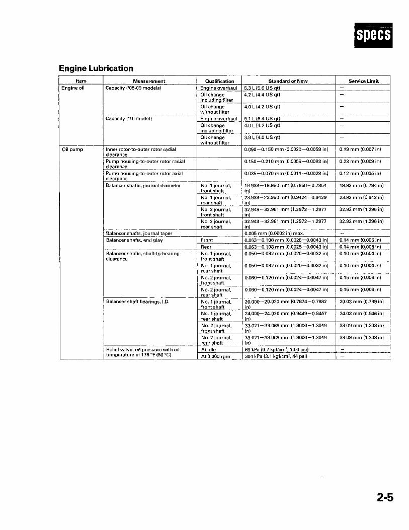
Engine Lubrication Item Measurement Qualification Standard or New Service Limit
Engine oil Capacity ('08-09 models) Engine overhaul 5.3 L (5.6 US qt) -Engine oil Capacity ('08-09 models) Oil change including filter
4.2 L (4.4 US qt) — Engine oil Capacity ('08-09 models)
Oil change without filter
4.0 L (4.2 US qt) —
Engine oil
Capacity ('10 model) Engine overhaul 5 1 L (5.4 US qt)
Engine oil
Capacity ('10 model) Oil change including filter
4.0 L (4.2 US qt) —
Engine oil
Capacity ('10 model)
Oil change without filter
3.8 L (4.0 US qt) —
Oil pump Inner rotor-to-outer rotor radial clearance
0.050-0.150 mm (0.0020-0.0059 in) 0.19 mm (0.007 in) Oil pump
Pump housing-to-outer rotor radial clearance
0.150-0.210 mm (0.0059-0.0083 in) 0.23 mm (0.009 in)
Oil pump
Pump housing-to-outer rotor axial clearance
0.035-0.070 mm (0.0014-0.0028 in) 0.12 mm (0.005 in)
Oil pump
Balancer shafts, journal diameter No. 1 journal, front shaft
19.938-19.950 mm (0.7850-0.7854 in)
19.92 mm (0.784 in)
Oil pump
Balancer shafts, journal diameter
No. 1 journal, rear shaft
23.938-23.950 mm (0.9424-0.9429 in)
23.92 mm (0.942 in)
Oil pump
Balancer shafts, journal diameter
No. 2 journal, front shaft
32.949-32.961 mm (1.2972-1.2977 in)
32.93 mm (1.296 in)
Oil pump
Balancer shafts, journal diameter
No. 2 journal, rear shaft
32.949-32.961 mm (1.2972-1.2977 in)
32.93 mm (1.296 in)
Oil pump
Balancer shafts, journal taper 0.005 mm (0.0002 in) max. _
Oil pump
Balancer shafts, end play Front 0.063-0.108 mm (0.0025-0.0043 in) 0.14 mm (0.006 in)
Oil pump
Balancer shafts, end play Rear 0.063-0.108 mm (0.0025-0.0043 in) 0.14 mm (0.006 in)
Oil pump
Balancer shafts, shaft-to-bearing clearance
No. 1 journal, front shaft
0.050-0.082 mm (0.0020-0.0032 in) 0.10 mm (0.004 in)
Oil pump
Balancer shafts, shaft-to-bearing clearance
No. 1 journal, rear shaft
0.050-0.082 mm (0.0020-0.0032 in) 0.10 mm (0.004 in)
Oil pump
Balancer shafts, shaft-to-bearing clearance
No. 2 journal, front shaft
0.060-0.120 mm (0.0024-0.0047 in) 0.15 mm (0.006 in)
Oil pump
Balancer shafts, shaft-to-bearing clearance
No. 2 journal, rear shaft
0.060-0.120 mm (0.0024-0.0047 in) 0.15 mm (0.006 in)
Oil pump
Balancer shaft bearings, I.D. No. 1 journal, front shaft
20.000-20.020 mm (0.7874-0.7882 in)
20.03 mm (0.789 in)
Oil pump
Balancer shaft bearings, I.D.
No. 1 journal, rear shaft
24.000-24.020 mm (0.9449-0.9457 in)
24.03 mm (0.946 in)
Oil pump
Balancer shaft bearings, I.D.
No. 2 journal, front shaft
33.021-33.069 mm (1.3000-1.3019 in)
33.09 mm (1.303 in)
Oil pump
Balancer shaft bearings, I.D.
No. 2 journal, rear shaft
33.021-33.069 mm (1.3000-1.3019 in)
33.09 mm (1.303 in)
Oil pump
Relief valve, oil pressure with oil temperature at 176 °F (80 °C)
At idle 69 kPa (0.7 kgf/cm 2,10.0 psi)
Oil pump
Relief valve, oil pressure with oil temperature at 176 °F (80 °C) At 3,000 rpm 304 kPa (3.1 kgf/cm 2,44 psi)
2-5

Standards and Service Limits
Cooling System Item Measurement Qualification Standard or New Service Limit
Radiator Coolant capacities (including engine, heater, hoses, and reservoir) ('08-09
Engine overhaul (M/T: DENSO)
8.2 L (2.17 US gal) —
models) Engine overhaul (M/T: TRAD)
8.1 L (2.14 US gal) —
' Engine overhaul (AT: DENSO)
8.1 L (2.14 US gal) —
Engine overhaul (A/T: TRAD)
8.0 L (2.11 US gal) —
Coolant change (M/T: DENSO)
6.1 L(1.61 US gal) •. —
Coolant change (M/T: TRAD)
6.0 L (1.59 US gal) — • •
Coolant change (A/T: DENSO)
. 6.0 L (1.59 US gal) —
Coolant change (A/T: TRAD)
5.9 L (1.56 US gal) —
Coolant capacities (including engine, heater, hoses, and reservoir) ('10
Engine overhaul (M/T: DENSO)
7.3 L (1.93 US gal) —
model) Engine overhaul (M/T: TRAD)
7.2 L (1.90 US gal) —
Engine overhaul (A/T: DENSO)
7.2 L (1.90 US gal) —
Engine overhaul (A/T: TRAD)
7.1 L(1.88 US gal) —
Coolant change (M/T: DENSO)
6.1 L(1.61 US gal) —
Coolant change (M/T- TRAD)
6.0 L (1.59 US gal) —
Coolant change (A/T: DENSO)
6.0 L (1.59 US gal) —
Coolant change (A/T: TRAD)
5.9 L (1.56 US gal) —
Coolant type NOTE: If the vehicle is regularly driven in very low temperatures (under -31 °F (-35 °C)), a 60% concentraction of coolant should be used (see page 10-6)
Honda Long Life Antifreeze/Coolant Type 2
Coolant reservoir
Coolant capacity 0.68 L (0.180 US gal) —
Radiator cap Opening pressure 93 -123 kPa (0.95-1.25 kgf/cm 2, 13.5 — 18 psi)
—
Thermostat Opening temperature Begins to open 169-176 °F (76-80 °C) Fully open 194 °F (90 °C)
Valve lift at fully open 8.0 mm (0.31 in) min. _
Fuel and Emissions Item Measurement Qualification Standard or New Service Limit
Fuel pressure regulator
Pressure with fuel pressure gauge connected
330-380 kPa (3.4-3.9 kgf /cm 2 ,48-55 psi)
—
Fuel tank Capacity 70 L (18.5 US gal) Engine idle Idle speed without load A/Tin N or P 800 ± 50 rpm
M/T in neutral 780 ± 50 rpm Idle speed with high electric load A/Tin N or P 800 ± 50 rpm (A/C switch on, temperature set to max cool, blower fan on high, rear window defogger on, and headlights on high beam)
M/T in neutral 780 ± 50 rpm
Clutch Item Measurement Qualification Standard or New Service Limit
Clutch pedal Height from floor 174 mm (6.9 in) Stroke 130-140 mm (5.1-5.5 in)
2 - 6 tin UP

Clutch (cont'd) Item Measurement Qualification Standard or New Service Limit
Flywheel Runout on clutch mating surface 0.05 mm (0.002 in) max. 0.15 mm (0.006 in) Clutch disc Rivet head depth 1.15-1.75 mm (0.045-0.069 in) 0.7 mm (0.03 in) Clutch disc
Thickness 7.30-7.90 mm (0.287-0.311 in) 6.0 mm (0.24 in) Pressure plate Warpage 0.03 mm (0.001 in) max. 0 15 mm (0.006 in) Pressure plate
Evenness of the height of the diaphragm spring fingers
0.6 mm (0.02 in) max. 0.8 mm (0.03 in)
Manual Transmission and M/T Differential Item Measurement Qualification Standard or New Service Limit
Manual transmission fluid
Capacity : use genuine Honda MTF Fluid change 1.9 L (2.0 US qt) _ Manual transmission fluid
Capacity : use genuine Honda MTF Overhaul 2.0 L (2.1 USqt) -
Mainshaft End play 0.11 -0 .17 mm (0.004-0.007 in) Adjust Mainshaft Diameter of bushing contact area 20.80-20.85 mm (0.819-0.821 in) 20.75 mm (0.817 in)
Mainshaft
Diameter of ball bearing contact area (clutch housing side)
27.977-27.990 mm (1.1015-1.1020 in)
27.92 mm (1.099 in)
Mainshaft
Diameter of needle bearing contact area
38.984-39.000 mm (1.5348-1.5354 in)
38.93 mm (1.533 in)
Mainshaft
Diameter of ball bearing contact area (transmission housing side)
27.987-28.000 mm (1.1018-1.1024 in)
27.93 mm (1.100 in)
Mainshaft
Diameter of 4th/5th gears distance collar contact area
31.984-32.000 mm (1.2592-1.2598 in)
31.93 mm (1.257 in)
Mainshaft
Runout 0.02 mm (0.001 in) max. 0.05 mm (0.002 in) Mainshaft 3rd, 4th, 5th gear
I.D. 44.009-44.025 mm (1.7326-1.7333 in)
44.08 mm (1.735 in) Mainshaft 3rd, 4th, 5th gear
Clearance 2nd-3rd 0.06-0.16 mm (0.002-0.006 in) 0.25 mm (0.010 in)
Mainshaft 3rd, 4th, 5th gear
End play (distance collar side) 4th, 5th 0.06-0.16 mm (0.002-0.006 in) 0.25 mm (0.010 in)
Mainshaft 3rd, 4th, 5th gear
Thickness 23.92-23.97 mm (0.942-0.944 in) 23.80 mm (0.937 in) Mainshaft 4th, 5th gear distance collar
I.D. 32.00-32.01 mm (1.2598-1.2602 in) 32.02 mm (1.261 in) Mainshaft 4th, 5th gear distance collar
O.D. 38.989-39.000 mm (1.5350-1.5354 in)
38.94 mm (1.533 in) Mainshaft 4th, 5th gear distance collar
Overall Length 51.95-52.05 mm (2.045-2.049 in) -
Mainshaft 4th, 5th gear distance collar
Length of needle bearing contact area 4th, 5th 24.03-24.08 mm (0.946-0.948 in) _ MBS distance collar
I.D. 28.00-28.10 mm (1.102-1.106 in) •: 28.12 mm (1.107 in) MBS distance collar Length 23.95-24.05 mm (0.943-0.947 in) Countershaft Diameter of needle bearing contact
area (clutch housing side) 40.000-40.015 mm (1.5748-1.575-4 in)
39.95 mm (1.573 in) Countershaft
Diameter of ball bearing contact area (transmission housing side)
30.020-30.033 mm (1.1819-1.1824 in)
29.97 mm (1.180 in)
Countershaft
Diameter of 1st gear distance collar contact area
39.937-39.950 mm (1.5723-1.5728 in)
39.88 mm (1.570 in)
Countershaft
Runout 0.02 mm (0.001 in) max. 0.05 mm (0.002 in)
Countershaft
35 mm shim-to-bearing inner race clearance
0.04-0.10 mm (0.002-0.004 in) Adjust
2-7

Standards and Service Limits
Manual Transmission and M/T Differential (cont'd) Item Measurement Qualification Standard or New Service Limit
Countershaft 1st, 2nd gear
I.D. 52.010-52.029 mm (2.0476-2.0484 in)
52.08 mm (2.050 in) Countershaft 1st, 2nd gear
Clearance 2nd-3rd 0.06-0.16 mm (0.002-0.006 in) 0.25 mm (0.010 in)
Countershaft 1st, 2nd gear
End play (distance collar side) 1st 0.06-0.16 mm (0.002-0.006 in) 0.25 mm (0.010 in)
Countershaft 1st, 2nd gear
Thickness 1st 22.92-22.97 mm (0.902-0.904 in) 22.87 mm (0.900 in)
Countershaft 1st, 2nd gear
Thickness 2nd 27.92-27.97 mm (1.099-1.101 in) 27.87 mm (1.097 in)
Countershaft 1st, 2nd gear distance collar
I.D. 39.95-39.96 mm (1.5728-1.5732 in) 39.97 mm (1.574 in) Countershaft 1st, 2nd gear distance collar
O.D. 46.989-47.000 mm (1.8500-1.8504 in)
46.94 mm (1.848 in) Countershaft 1st, 2nd gear distance collar
Length 1st 23.03-23.08 mm (0.907-0.909 in) -
Countershaft 1st, 2nd gear distance collar
Length 2nd 28.03-28.08 mm (1.104-1.106 in) -
Reverse idler gear
I.D. 20.016-20.043 mm (0.7880-0.7891 in)
20.90 mm (0.823 in) Reverse idler gear
Gear-to-reverse gear shaft clearance 0.036-0.084 mm (0.0014-0.0033 in) 0.16 mm (0.006 in) Synchro ring Ring-to-gear clearance (ring pushed
against gear) 0.70-1.49 mm (0.028-0.059 in) 0.4 mm (0.02 in)
Double cone synchro
Outer synchro ring-to-synchro cone clearance (ring pushed against gear)
3rd gear 0.46-0.97 mm (0.018-0.038 in) 0.3 mm (0.01 in) Double cone synchro
Outer synchro ring-to-synchro cone clearance (ring pushed against gear) 4th gear 0.70-1.19 mm (0.028-0.047 in) 0.3 mm (0.01 in)
Double cone synchro
Synchro cone-to-gear clearance (ring pushed against gear)
3rd gear 0.51-1.07 mm (0.020-0.042 in) 0.3 mm (0.01 in)
Double cone synchro
Synchro cone-to-gear clearance (ring pushed against gear) 4th gear 0.50-1.04 mm (0.020-0.041 in) 0.3 mm (0.01 in)
Double cone synchro
Outer synchro ring-to-gear clearance (ring pushed against gear)
0.95-1.68 mm (0.037-0.066 in) 0.6 mm (0.02 in)
Triple cone synchro
Outer synchro ring-to-synchro cone clearance (ring pushed against gear)
0.70-1.19 mm (0.028-0.047 in) 0.3 mm (0.01 in) Triple cone synchro
Synchro cone-to-gear clearance (ring pushed against gear)
0.50-1.04 mm (0.020-0.041 in) 0.3 mm (0.01 in)
Triple cone synchro
Outer synchro ring-to-gear clearance (ring pushed against gear)
0.95-1.68 mm (0.037-0.066 in) 0.6 mm (0.02 in)
Shift fork Finger thickness 7.4-7.6 mm (0.29-0.30 in) Shift fork Fork-to-synchro sleeve clearance 0.35-0.65 mm (0.014-0.026 in) 1.0 mm (0.04 in)
Reverse shift fork
Finger width 13.4-13.7 mm (0.53-0.54 in) -Reverse shift fork Fork-to-reverse idler gear clearance 0.20-0.59 mm (0.008-0.023 in) 1.2 mm (0.05 in) Shift arm I.D. 13.973-14.000 mm (0.5501-0.5512
in) — Shift arm
Fingerwidth 16.9-17.0 mm (0.665-0.669 in) -Shift arm
Shift arm-to-shift fork clearance 0.2-0.5 mm (0.01 -0 .02 in) 0.6 mm (0.02 in) Select lever Finger width 14.85-14.95 mm (0.585-0.589 in) -
Change lever Shaft-to-select lever clearance 0.05-0.25 mm (0.002-0.010 in) 0.50 mm (0.020 in) Change lever Groove width 15.00-15.10 mm (0.591 -0 .594 in) -
Change lever
Shaft-to-shift arm clearance 0.013-0.070 mm (0.0005-0.0028 in) 0.1 mm (0.00 in) M/T differential carrier
Backlash 0.05-0.15 mm (0.002-0.006 in) —
M/T differential 80 mm shim
80 mm shim-to-bearing outer race clearance in transmission housing
0—0.10 mm (0.0-0.004 in) Adjust
2-8

Automatic Transmission and A/T Differential Item Measurement Qualification Standard or New Service Limit
Automatic Capacity: use genuine Honda ATF-Z1 Fluid change 2.5 L (2.6 US qt) - •
transmission fluid
Overhaul 6.5 L (6.9 US qt) -ATF pressure Line pressure At 2,000 rpm in N
or P 927-985 kPa (9.45-10.05 kgf/cm 2,134 - 1 4 3 psi)
877 kPa (8.95 kgf/cm 2, 127 psi)
1st clutch pressure At 2,000 rpm in 1 917-995 kPa (9.35-10.15 kgf/cm 2,133 — 144 psi)
867 kPa (8.85 kgf/cm 2, 126 psi)
2nd clutch pressure At 2,000 rpm in 2 917-995 kPa (9.35-10.15 kgf/cm 2,133 — 144 psi)
867 kPa (8.85 kgf/cm 2, 126 psi)
3rd clutch pressure At 2,000 rpm in 3rd gear in D
917-995 kPa (9.35-10.15 kgf/cm2,133 — 144 psi)
867 kPa (8.85 kgf/cm 2, 126 psi)
4th clutch pressure At 2,000 rpm in 4th gear in D
917-995 kPa (9.35-10.15 kgf/cm 2,133 — 144 psi)
867 kPa (8.85 kgf/cm 2, 126 psi)
5th clutch pressure At 2,000 rpm in 5th gear in D
917-995 kPa (9.35-10.15 kgf/cm 2,133 - 1 4 4 psi)
867 kPa (8.85 kgf/cm 2, 126 psi)
Torque Stall speed 2,100 rpm -converter Check with vehicle on level ground Service limit 1,950-2,250 rpm -Clutch Clearance between clutch end-plate 1st 1.38-1.58 mm (0.054-0.062 in)
and top disc 2nd 1.14-1.34 mm (0.045-0.053 in) _ 3rd 1.23-1.43 mm (0.048-0.056 in) -4th, 5th 0.93-1.13 mm (0.037-0.044 in) _
Clutch return spring free length 1st, 2nd, 3rd 45.1 mm (1.78 in) 43.1 mm (1.70 in) 4th, 5th 33.5 mm (1.32 in) 31.5 mm (1.24 in
Clutch disc thickness 1.94 mm (0.076 in) Clutch plate thickness 1st, 3rd 1.6 mm (0.063 in) When discolored
2nd, 4th, 5th 2.0 mm (0.079 in) When discolored Clutch wave-plate phase difference 1st <2PLCS> 0.15-0.25 mm (0.006-0.010 in) 0.13 mm (0.005 in)
2nd, 3rd, 4th, 5th <2PLCS>
0.10-0.20 mm (0.004 -0.008 in) 0.08 mm (0.003 in)
1 st clutch end-plate thickness Mark 1 2.6 mm (0.102 in) When discolored Mark 2 2.7 mm (0.106 in) When discolored Mark 3 2.8 mm (0.110 in) When discolored Mark 4 2.9 mm (0.114 in) When discolored Mark 5 3.0 mm (0.118 in) When discolored Mark 6 3.1 mm (0.122 in) When discolored Mark 7 3.2 mm (0.126 in) When discolored Mark 8 3.3 mm (0.130 in) When discolored Mark 9 3.4 mm (0.134 in) When discolored
2nd clutch end-plate thickness Mark 1 2.6 mm (0.102 in) When discolored Mark 2 2.7 mm (0.106 in) When discolored Mark 3 2.8 mm (0.110 in) When discolored Mark 4 2.9 mm (0.114 in) When discolored Mark 5 3.0 mm (0.118 in) When discolored Mark 6 3.1 mm (0.122 in) When discolored Mark 7 3.2 mm (0.126 in) When discolored Mark 10 2.4 mm (0.094 in) When discolored Mark 11 2.5 mm (0.098 in) When discolored
3rd, 4th and 5th clutch end-plate Ma rk l 2.1 mm (0.083 in) When discolored thickness Mark 2 2.2 mm (0.087 in) When discolored
Mark 3 2.3 mm (0.091 in) When discolored Mark 4 2.4 mm (0.094 in) When discolored Mark 5 2.5 mm (0.098 in) When discolored Mark 6 2.6 mm (0.102 in) When discolored Mark 7 2.7 mm (0.106 in) When discolored Mark 8 2.8 mm (0.110 in) When discolored Mark 9 2.9 mm (0.114 in) When discolored
2-9
Standards and Service Limits
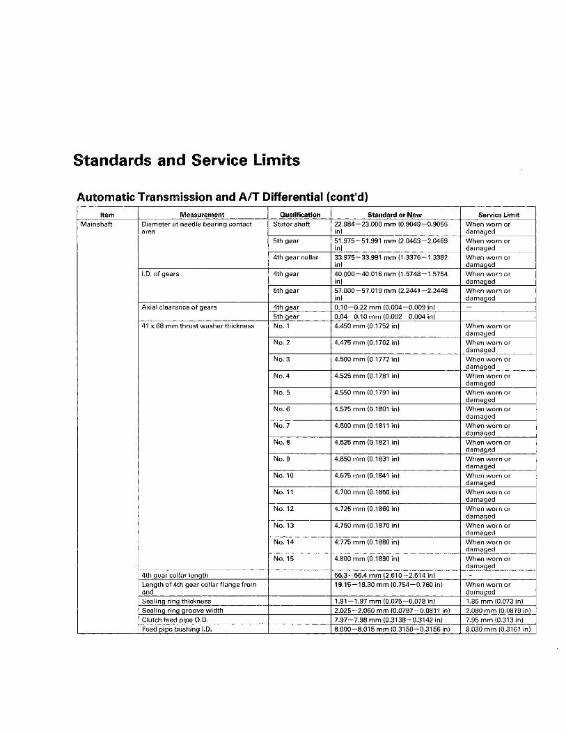
Automatic Transmission and A/T Differential (cont'd) Item Measurement Qualification Standard or New Service Limit
Mainshaft Diameter at needle bearing contact area
Stator shaft 22.984-23.000 mm (0.9049-0.9055 in)
When worn or damaged
5th gear 51.975-51.991 mm (2.0463-2.0469 in)
When worn or damaged
4th gear collar 33.975-33.991 mm (1.3376-1.3382 in)
When worn or damaged
I.D. of gears 4th gear 40.000-40.016 mm (1.5748-1.5754 in)
When worn or damaged
5th gear 57.000-57.019 mm (2.2441 -2.2448 in)
When worn or damaged
Axial clearance of gears 4th gear 0.10-0.22 mm (0.004-0.009 in) 5th gear 0.04-0.10 mm (0.002-0.004 in) -
41 x 68 mm thrust washer thickness No. 1 4.450 mm (0.1752 in) When worn or damaged
No. 2 4.475 mm (0.1762 in) When worn or damaged
No. 3 4.500 mm (0.1772 in) When worn or damaged
No. 4 4.525 mm (0.1781 in) When worn or damaged
No. 5 4.550 mm (0.1791 in) When worn or damaged
No. 6 4.575 mm (0.1801 in) When worn or damaged
No. 7 4.600 mm (0.1811 in) When worn or damaged
No. 8 4.625 mm (0.1821 in) When worn or damaged
No. 9 4.650 mm (0.1831 in) When worn or damaged
No. 10 4.675 mm (0.1841 in) When worn or damaged
No. 11 4.700 mm (0.1850 in) When worn or damaged
No. 12 4.725 mm (0.1860 in) When worn or damaged
No. 13 4.750 mm (0.1870 in) When worn or damaged
No. 14 4:775 mm (0.1880 in) When worn or damaged
No. 15 4.800 mm (0.1890 in) When worn or damaged
4th gear collar length 66.3-66.4 mm (2.610-2.614 in) _ Length of 4th gear collar flange from end
19.15-19.30 mm (0.754-0.760 in) When worn or damaged
Sealing ring thickness 1.91-1.97 mm (0.075-0.078 in) 1.86 mm (0.073 in) Sealing ring groove width 2.025-2.060 mm (0.0797-0.0811 in) 2.080 mm (0.0819 in) Clutch feed pipe O.D. 7.97-7.98 mm (0.3138-0.3142 in) 7.95 mm (0.313 in) Feed pipe bushing I.D. 8.000-8.015 mm (0.3150-0.3156 in) 8.030 mm (0.3161 in)

Automatic Transmission and A/T Differential Icont'd) Item Measurement Qualification Standard or New Service Limit
Countershaft Diameter at needle bearing contact area
# • -
Torque converter housing bearing
36.005-36.015 mm (1.4175-1.4170 in)
When worn or . damaged
Countershaft Diameter at needle bearing contact area
# • -
4th gear 34.982-34.998 mm (1.3772-1.3779 in)
When worn or damaged
Countershaft Diameter at needle bearing contact area
# • -
Reverse gear 39.979-40.000 mm (1.5740-1.5748 in)
When worn or damaged
Countershaft
I.D. of gears 4th gear 41.000-41.016 mm (1.6142-1.6148 in)
When worn or damaged
Countershaft
I.D. of gears
Reverse gear 46.000-46.016 mm (1.8110-1.8116 in)
When worn or damaged
Countershaft
Axial clearance of gears 4th gear 0.04-0.12 mm (0.002-0.005 in) _
Countershaft
Axial clearance of gears 5th gear 0—0.48 mm (0—0.019 in) -
Countershaft
Axial clearance of gears
Reverse gear 0.10-0.25 mm (0.004-0.010 in)
Countershaft
Collar, 35 x 47 x 7.8 mm thickness 7.8 mm (0.31 in) _
Countershaft
Collar, 37 x 41 x 54.3 mm length 54.25-54.30 m m (2.136-2.138 in)
Countershaft
Reverse selector hub width 25.45-25.65 mm (1.002-1.010 in) —
Countershaft
Reverse selector hub O.D. 55.87-55.90 mm (2.200-2.201 in) When worn or damaged
2-11

Standards and Service Limits
Automatic Transmission and A/T Differential (cont'd) Item Measurement Qualification Standard or New Service Limit
Secondary shaft Diameter at needle bearing contact area
1st gear 39.986-39.999 mm (1.5742-1.5748 in)
When worn or damaged
2nd gear 39.986-39.999 mm (1.5742-1.5748 in)
When worn or damaged
3rd gear collar 36.975-36.991 mm (1.4557-1.4563 in)
When worn or damaged
I.D. of gears 1st gear 47.000-47.016 mm (1.8504-1.8510 in)
When worn or damaged
2nd gear 46.000-46.016 mm (1.8110-1.8116 in)
When worn or damaged
3rd gear 43.000-43.016 mm (1.6929-1.6935 in)
When worn or damaged
Axial clearance of gears 1st gear 0.04-0.12 mm (0.002-0.005 in) -2nd gear 0.04-0.12 mm (0.002-0.005 in) 3rd gear 0.10-0.22 mm (0.004-0.009 in)
37 x 58 mm thrust washer thickness No. 1 3.900 mm (0.154 in) When worn or damaged
No. 2 3.925 mm (0.155 in) When worn or damaged
No. 3 3.950 mm (0.156 in) When worn or damaged
No. 4 3.975 mm (0.156 in) When worn or damaged
No. 5 4.000 mm (0.157 in) When worn or damaged
No. 6 4.025 mm (0.158 in) When worn or damaged
No. 7 4.050 mm (0.159 in) When worn or damaged
No. 8 4.075 mm (0.160 in) When worn or damaged
No. 9 4.100 mm (0.161 in) When worn or damaged
No. 10 4.125 mm (0.162 in) When worn or damaged
No. 11 4.150 mm (0.163 in) When worn or damaged
No. 12 4.175 mm (0.164 in) When worn or damaged
No. 13 4.200 mm (0.165 in) When worn or damaged
No. 14 4.225 mm (0.166 in) When worn or damaged
No. 15 4.250 mm (0.167 in) When worn or damaged
No. 16 4.275 mm (0.168 in) When worn or damaged
No. 17 4.300 mm (0.169 in) When worn or damaged
No. 18 4.325 mm (0.170 in) When worn or damaged
No. 19 4.350 mm (0.171 in) When worn or damaged
No. 20 4.375 mm (0.172 in) When worn or damaged
2-12

Automatic Transmission and A/T Differential: (cont'd) Item Measurement Qualification Standard or New Service Limit
Secondary shaft (cont'd)
40 x 51.5 mm thrust washer thickness No. 1 4.80 mm (0.189 in) When worn or damaged
Secondary shaft (cont'd)
40 x 51.5 mm thrust washer thickness
No. 2 4.85 mm (0.191 in) When worn or damaged
Secondary shaft (cont'd)
40 x 51.5 mm thrust washer thickness
No. 3 4.90 mm (0.193 in) When worn or damaged
Secondary shaft (cont'd)
40 x 51.5 mm thrust washer thickness
No. 4 4.95 mm (0.195 in) When worn or damaged
Secondary shaft (cont'd)
40 x 51.5 mm thrust washer thickness
No. 5 5.00 mm (0.197 in) When worn or damaged
Secondary shaft (cont'd)
40 x 51.5 mm thrust washer thickness
No. 6 5.05 mm (0.199 in) When worn or damaged
Secondary shaft (cont'd)
3rd gear collar length 43.9-44.0 mm (1.728-1.732 in) -
Secondary shaft (cont'd)
Length'of 3rd gear collar flange from end
5.25-5.40 mm (0.207-0.213 in) When worn or damaged
Secondary shaft (cont'd)
Sealing ring thickness 1.91-1.97 mm (0.0752-0.0776 in) 1.86 mm (0.0732 in)
Secondary shaft (cont'd)
Sealing ring groove width 2.025-2.060 mm (0.0797-0.0811 in) 2.080 mm (0.0819 in)
Secondary shaft (cont'd)
Clutch feed pipe O.D. 1st 6.97-6.98 mm (0.2744-0.2748 in) 6.95 mm (0.2736 in)
Secondary shaft (cont'd)
Clutch feed pipe O.D. 3rd 11.47-11.48 mm (0.4528-0.4535 in) 11.45 mm (0.4508 in)
Secondary shaft (cont'd)
Feed pipe bushing I.D. 1st clutch 7.018-7.030 mm (0.2763-0.2768 in) 7.045 mm (0.2774 in)
Secondary shaft (cont'd)
Feed pipe bushing I.D. 3rd clutch 11.500-11.518 mm (0.4528-0.4535
in) 11.530 mm (0.4539 in)
Secondary shaft (cont'd)
ATF guide collar of sealing ring contact I.D.
29.000-29.021 mm (1.1417-1.1426 in)
29.05 mm (1.144 in)
Idler gear shaft Diameter at needle bearing contact area
End cover side 32.003-32.013 mm (1.2600-1.2604 in)
When worn or damaged
Idler gear shaft
Thickness of cotters 1.39-1.42 mm (0.055-0.056 in) Reverse Idler gear
Reverse idler gear shaft diameter at needle bearing contact area
14.99-15.00 mm (0.590-0.591 in) When worn or damaged
Reverse Idler gear
I.D. 20.007-20.020 mm (0.7877-0.7882 in)
When worn or damaged
Reverse Idler gear
I.D. of transmission housing of gear shaft contact area
14.800-14.818 mm (0.5827-0.5834 in)
—
Reverse Idler gear
I.D. of reverse idler gear shaft holder 14.800-14.824 mm (0.5827-0.5836 in)
When worn or damaged
ATF pump ATF pump thrust clearance 0.03-0.06 mm (0.001 -0.002 in) 0.07 mm (0.003 in) ATF pump Clearance between ATF pump gear and main valve body
Drive gear 0.210-0.265 mm (0.0083-0.0104 in) __
ATF pump Clearance between ATF pump gear and main valve body Driven gear 0.070-0.125 mm (0.0028-0.0049 in)
ATF pump
ATF pump driven gear I.D. 14.016-14.034 mm (0.5518-0.5525 in)
When worn or damaged
ATF pump
ATF pump driven gear shaft O.D. 13.980-13.990 mm (0.5504-0.5508 in)
When worn or damaged
Stator shaft I.D. at needle bearing contact area Torque converter side
27.000-27.021 mm (1.0630-1.0638 in)
When worn or damaged
Stator shaft I.D. at needle bearing contact area
ATF pump side 29.000-29.021 mm (1.1417-1.1426 in)
—
Stator shaft
I.D. at mainshaft sealing ring contact area
29.000-29.021 mm (1.1417-1.1426 in)
29.05 mm (1.144 in)
Reverse shift fork
Fork finger thickness 5.90-6.00 mm (0.232-0.236 in) 5.40 mm (0.213 in)
Park gear and pawl
When worn or damaged
Servo body Shift fork shaft bore I.D. 14.000-14.010 mm (0.5512-0.5516 in)
— Servo body
Shift fork shaft valve bore I.D. 37.000-37.039 mm (1.4567-1.4582 in)
37.045 mm (1.4585 in)
Regulator valve body
Mainshaft sealing ring contact I.D. 29.000-29.021 mm (1.1417-1.1426 in)
29.05 mm (1.144 in)
2-13

Standards and Service Limits
Automatic Transmission and A/T Differential (cont'd) Item Measurement Qualification Standard or New Service Limit
Main valve body Shift valve A spring Wire diameter 0.8 mm (0.031 in) _ spring (see page 14-277)
O.D. 5.6 mm (0.220 in) _ spring (see page 14-277) Free length 28.1 mm (1.106 in) -
No. of coil 15.9 Shift valve B spring Wire diameter 0.8 mm (0.031 in) -
O.D. 5.6 mm (0.220 in) _ Free length 28.1 mm (1.106 in) -No. of coil 15.9
Shift valve C spring Wire diameter 0.8 mm (0.031 in) -O.D. 5.6 mm (0.220 in) _ Free length 28.1 mm (1.106 in) _ No. of coil 15.9
Shift valve E spring Wire diameter 0.8 mm (0.031 in) * O.D. 5.6 mm (0.220 in) -
Free length 28.1 mm (1.106 in) No. of coil 15.9
Relief valve spring Wire diameter 1.0 mm (0.039 in) O.D. 9.6 mm (0.378 in) Free length 34.1 mm (1.343 in) -No. of coil 10.2
Lock-up control valve spring Wire diameter 0.65 mm (0.026 in) O.D. 7.1 mm (0.280 in) Free length 23.1 mm (0.909 in) -No. of coil 12.7
Cooler check valve spring Wire diameter 0.85 mm (0.033 in) -O.D. 6.6 mm (0.260 in) -Free length 27.0 mm (1.063 in) No. of coil 11.3
Servo control valve spring Wire diameter 0.7 mm (0.028 in) -O.D. 6.6 mm (0.260 in) Free length 35.7 mm (1.406 in) No. of coil 17.2
2 - 1 4

Automatic Transmission and A/T Differential (cont'd) Item Measurement Qualification Standard or New Service Limit
Regulator valve 1 st accumulator spring A Wire diameter 2.4 mm (0.094 in) _ body spring (see page 14-279)
O.D. 18.6 mm (0.732 in) body spring (see page 14-279) Free length 49.0 mm (1.929 in)
No. of coil 7.1 1 st accumulator spring B Wire diameter 2.3 mm (0.091 in)
O.D. 12.2 mm (0.480 in) Free length 31.5 mm (1.240 in) No. of coil 6.6
3rd accumulator spring Wire diameter 2.5 mm (0.098 in) -O.D. 14.6 mm (0.575 in) -Free length 29.4 mm (1.157 in) _ No. of coil 4.9
Regulator valve spring A Wire diameter 1.85 mm (0.073 in) —
O.D. 14.7 mm (0.579 in) Free length 83.0 mm (3.268 in) -No. of coil 14.9
Regulator valve spring B Wire diameter 1.6 mm (0.063 in) -O.D. 9.2 mm (0.362 in) Free length 44.0 mm (1.732 in) -No. of coil 12.5
Stator reaction spring Wire diameter 4.5 mm (0.177 in) -O.D. 35.4 mm (1.394 in) -Free length 30.3 mm (1.193 in) -No. of coil 1.92
Lock-up shift valve spring Wire diameter 1.0 mm (0.039 in) -O.D. 6.6 mm (0.260 in) Free length 35.5 mm (1.398 in) No. of coil 18.2
Torque converter check valve spring Wire diameter 1.2 mm (0.047 in) _ O.D. 8.6 mm (0.339 in) -Free length 33.8 mm (1.331 in) -No. of coil 12.2
Servo body 2nd accumulator spring A Wire diameter 2.1 mm (0.083 in) spring (see page 14-280)
O.D. 16.6 mm (0.654 in) -spring (see page 14-280) Free length 48.7 mm (1.917 in)
No. of coil 8.4 2nd accumulator spring B Wire diameter 2.1 mm (0.083 in) —
O.D. 10.8 mm (0.425 in) -Free length 34.0 mm (1.339 in) -No. of coil 8.2
4th accumulator spring A Wire diameter 2.4 mm (0.094 in) -O.D. 18.6 mm (0.732 in) Free length 49.0 mm (1.929 in) No. of coil 7.1
4th accumulator spring B Wire diameter 2.3 mm (0.091 in) -O.D. 12.2 mm (0.480 in) -Free length 31.5 mm (1.240 in) -No. of coil 6.6
5th accumulator spring Wire diameter 2.5 mm (0.098 in) -O.D. 14.6 mm (0.575 in) -Free length 29.9 mm (1.177 in) No. of coil 4.9
Shift valve D spring Wire diameter 0.8 mm (0.031 in) _ O.D. 5.6 mm (0.220 in) -Free length 28.1 mm (1.106 in) -No. of coil 15.9
2-15

Standards and Service Limits
Automatic Transmission and A/T Differential (cont'd) Item Measurement Qualification Standard or New Service Limit
A/T differential carrier
Pinion shaft contact area I.D. 18.000-18.025 mm (0.7087-0.7096 in)
— A/T differential carrier
Driveshaft contact area I.D. 28.021-28.051 mm (1.1032-1.1044 in)
—
A/T differential carrier
Clearance between carrier and pinion shaft
0.013-0.054 mm (0.0005-0.0021 in) 0.1 mm (0.004 in)
A/T differential carrier
Clearance between carrier and driveshaft
0.071 -0.117 mm (0.0028-0.0046 in) 0.12 mm (0.005 in)
A/T differential carrier
Tapered roller bearing starting torque (preload)
For new bearing 2.7-3.9 N-m (0.28-0.40 kgf-m, 2 . 0 -2.9 ibf-ft)
Adjust
A/T differential carrier
Tapered roller bearing starting torque (preload)
For reused bearing
2.5-3.6 N-m (0.25-0.37 kgf-m, 1.8-2.7 Ibf-ft)
Adjust
A/T differential carrier
Final driven gear backlash 0.086-0.142 mm (0.0034-0.0056 in) 0.2 mm (0.008 in) A/T differential pinion gear
Backlash 0.05-0.15 mm (0.002-0.006 in) _ A/T differential pinion gear I.D. 18.042-18.066 mm (0.7103-0.7113
in) —
A/T differential pinion gear
Clearance between pinion gear and pinion shaft
0.055-0.095 mm (0.0022-0.0037 in) 0.12 mm (0.005 in)
Steering Item Measurement Qualification Standard or New Service Limit
Steering wheel Rotational play measured at outside edge
0—10 mm (0-0.39 in) — Steering wheel
Initial turning load measured at outside edge with engine running
29 N (3.0 kgf, 6.6 ibf) —
Gearbox Angle of rack guide screw loosened from locked position
1 5 ± 5 °
Pump Output pressure with shut-off valve closed
8,140-8,830 kPa (83-90 kgf/cm 2, 1,180-1,280 psi)
—
Power steering fluid
Capacity: use Honda power steering fluid
System capacity 1.05 L (1.11 USqt) _ Power steering fluid
Capacity: use Honda power steering fluid Reservoir
capacity 0.32 L (0.34 US qt) —
Suspension Item Measurement Qualification Standard or New Service Limit
Wheel alignment Camber Front 0 ° 0 0 ' + 3 0 ' _ 4 5 -Wheel alignment Camber Rear - 1 ° 0 0 ' + 3 0 ' _ 4 5 .
Wheel alignment
Caster Front (4-door) 3 o 4 8 .+o-25 n n h
Wheel alignment
Caster Front (2-door) 3 ° 47 ' + 0 ° 2 5 ' , - 0 5 -
Wheel alignment
Total toe-in Front 0 ± 2 mm (0+0.08 in)
Wheel alignment
Total toe-in Rear 2 ± 2 mm (0.08+0.08 in)
Wheel alignment
Front wheel turning angle Inward 39° 0 0 ' ± 2 °
Wheel alignment
Front wheel turning angle Outward (reference)
31 ° 5 0 '
Wheel Aluminum wheel runout Axial 0 -0 .7 mm (0-0.03 in) 2.0 mm (0.08 in) Wheel Aluminum wheel runout Radial 0—0.7 mm (0—0.03 in) 1.5 mm (0.06 in)
Wheel
Steel wheel runout Axial 0—1.0 mm (0-0.04 in) 2.0 mm (0.08 in)
Wheel
Steel wheel runout Radial 0 -1 .0 mm (0-0.04 in) 1.5 mm (0.06 in)
Wheel bearing End play Front 0—0.05 mm (0-0.002 in) -Wheel bearing End play Rear . 0—0.05 mm (0-0.002 in) -
2-16

Brakes Item Measurement Qualification Standard or New Service Limit
Parking brake Number of clicks when lever pulled with 196 N (20 kgf,44 Ibf) offeree
7 to 9 clicks
Brake pedal Pedal height (carpet moved aside) M/T 156 mm (6.1 in) A/T 155 mm (6.1 in)
Free play 1 —5 mm (0.04—0.20 in) -Brake disc Thickness Front (NISSIN) 27.9-28.1 mm (1.10-1.11 in) 26.0 mm (1.02 in)
Front (AKEBONO)
22.9-23.1 mm (0.90-0.91 in) 21.0 mm (0.83 in)
Rear 8.9-9.1 mm (0.35-0.36 in) 8.0 mm (0.31 in) Runout - 0.04 mm (0.0016 in) Parallelism — 0.015 mm (0.0006 in)
Brake pad Thickness Front (NISSIN) 10.5-11.2 mm (0.41 -0 .44 in) 1.6 mm (0.06 in) Front (AKEBONO)
10.5-10.8 mm (0.41 -0 .43 in) 1.6 mm (0.06 in)
Rear 8.3-9.0 mm (0.33-0.35 in) 1.0 mm (0.04 in)
Air Conditioning Item Measurement Qualification Standard or New Service Limit
Refrigerant Type HFC-134a(R-134a) Capacity of system 400-450 g (14.1-15.9 oz)
Refrigerant oil Type DENSO ND-OIL 8 (P/N 38897-PR7-A01AH or 38999-PR7-A01) Capacity of components Condenser 35 m l (1 1/5 fl-oz)
Evaporator 35mL(1 1/5 fl-oz) Each line and hose
10 mL (1/3 fl-oz)
Receiver/Dryer 10mL(1/3 fl-oz) Compressor 7 0 - 8 2 mL (2 3 /8 -2 7/9 fl-oz)
Compressor Field coil resistance At 68 °F (20 °C) 3.9-4.3 0 PuIley-to-armature plate clearance 0.35-0.60 mm (0.014-0.024 in) | -
2-17

Design Specifications
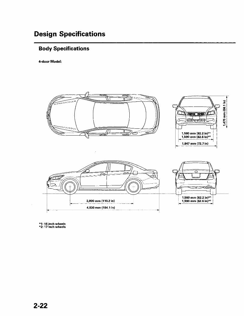
Item Measurement Qualification Specification DIMENSIONS (4-door)
Overall length 4,930 mm (194.1 in) DIMENSIONS (4-door) Overall width 1,847 mm (72.7 in) DIMENSIONS (4-door)
Overall height 1,475 mm (58.1 in)
DIMENSIONS (4-door)
Wheelbase 2,800 mm (110.2 in)
DIMENSIONS (4-door)
Track Front (16 inch wheels) 1,580 mm (62.2 in)
DIMENSIONS (4-door)
Track Front (17 inch wheels) 1,590 mm (62.6 in)
DIMENSIONS (4-door)
Track
Rear (16 inch wheels) 1,580 mm (62.2 in)
DIMENSIONS (4-door)
Track
Rear (17 inch wheels) 1,590 mm (62.6 in)
DIMENSIONS (4-door)
Seating capacity Five (5) DIMENSIONS (2-door)
Overall length 4,849 mm (190.9 in) DIMENSIONS (2-door) Overall width 1,848 mm (72.7 in) DIMENSIONS (2-door)
Overall height 1,432 mm (56.3 in)
DIMENSIONS (2-door)
Wheelbase 2,740 mm (107.9 in)
DIMENSIONS (2-door)
Track Front 1,580 mm (62.2 in)
DIMENSIONS (2-door)
Track Rear 1,580 mm (62.2 in)
DIMENSIONS (2-door)
Seating capacity Five (5) WEIGHT (4-door)
Gross Vehicle Weight Rating (GVWR) USA models
LX, LX-P, LX PZEV, LX-P PZEV 1,950 kg (4,299 lbs) WEIGHT (4-door)
Gross Vehicle Weight Rating (GVWR) USA models
EX, EX-L, EX PZEV, EX-L PZEV 2,010 kg (4,431 lbs) WEIGHT (4-door)
Gross Vehicle Weight Rating (GVWR) Canada models
LX, LX-P 1,970 kg (4,343 lbs)
WEIGHT (4-door)
Gross Vehicle Weight Rating (GVWR) Canada models
EX, EX-L 2,030 kg (4,475 lbs)
WEIGHT (2-door)
Gross Vehicle Weight Rating (GVWR) USA models
LX, LX-S, LX PZEV 1,950 kg (4,299 lbs) WEIGHT (2-door)
Gross Vehicle Weight Rating (GVWR) USA models
EX, EX-L, EX PZEV, EX-L PZEV 2,000 kg (4,409 lbs) WEIGHT (2-door)
Gross Vehicle Weight Rating (GVWR) Canada models
LX 1,970 kg (4,343 lbs)
WEIGHT (2-door)
Gross Vehicle Weight Rating (GVWR) Canada models
EX, EX-L 2,020 kg (4,453 lbs)
ENGINE Type Water cooled, 4-stroke DOHC i-VTEC gasoline engine ENGINE Cylinder arrangement Inline 4-cylinder, transverse
ENGINE
Bore and stroke 87 x 99 mm (3.43 x 3.90 in)
ENGINE
Displacement 2,354 cm 3 (144 cu in)
ENGINE
Compression ratio 10.5
ENGINE
Valve train Chain drive, DOHC i-VTEC 4 valves per cylinder
ENGINE
Lubrication system Forced, wet sump, with trochoid pump
ENGINE
Fuel required Regular UNLEADED gasoline with 87 Pump Octane Number or higher
STARTER Type Gear reduction STARTER Nominal output 1.6 kW
STARTER
Nominal voltage 12 V
STARTER
Hour rating 30 seconds
STARTER
Rotation of direction Clockwise as viewed from drive end
2-1S
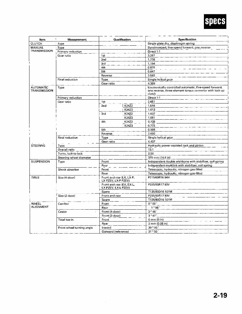
Item Measurement Qualification Specification CLUTCH Type Single plate dry, diaphragm spring MANUAL TRANSMISSION
Type Synchronized, five-speed forward, one reverse MANUAL TRANSMISSION Primary reduction Direct 1:1 MANUAL TRANSMISSION
Gear ratio 1st 3.267
MANUAL TRANSMISSION
Gear ratio 2nd 1.778
MANUAL TRANSMISSION
Gear ratio
3rd 1.154
MANUAL TRANSMISSION
Gear ratio
4th 0.870
MANUAL TRANSMISSION
Gear ratio
5th 0.647
MANUAL TRANSMISSION
Gear ratio
Reverse 3.583
MANUAL TRANSMISSION
Final reduction Type Single helical gear
MANUAL TRANSMISSION
Final reduction Gear ratio 4.389
AUTOMATIC TRANSMISSION
Type Electronically-controlled automatic, five-speed forward, one reverse, three-element torque converter with lock-up clutch
AUTOMATIC TRANSMISSION
Primary reduction Direct 1:1
AUTOMATIC TRANSMISSION
Gear ratio 1st 2.651
AUTOMATIC TRANSMISSION
Gear ratio 2nd K24Z2 1.516
AUTOMATIC TRANSMISSION
Gear ratio 2nd
K24Z3 1.613
AUTOMATIC TRANSMISSION
Gear ratio
3rd K24Z2 1.037
AUTOMATIC TRANSMISSION
Gear ratio
3rd K24Z3 1.081
AUTOMATIC TRANSMISSION
Gear ratio
4th K24Z2 0.738
AUTOMATIC TRANSMISSION
Gear ratio
4th K24Z3 0.772
AUTOMATIC TRANSMISSION
Gear ratio
5th 0.566
AUTOMATIC TRANSMISSION
Gear ratio
Reverse 2.000
AUTOMATIC TRANSMISSION
Final reduction Type Single helical gear
AUTOMATIC TRANSMISSION
Final reduction Gear ratio 4.437
STEERING Type Hydraulic power-assisted rack and pinion STEERING Overall ratio 13.1
STEERING
Turns, lock-to-lock 2.56
STEERING
Steering wheel diameter 370 mm (14.6 in) SUSPENSION Type Front Independent double wishbone with stabilizer, coil spring SUSPENSION Type
Rear Independent multilink with stabilizer, coil spring SUSPENSION
Shock absorber Front Telescopic, hydraulic, nitrogen gas-filled
SUSPENSION
Shock absorber Rear Telescopic, hydraulic, nitrogen gas-filled
TIRES Size (4-door) Front and rear (LX, LX-P, LX PZEV, LX-P PZEV)
P215/60R16 94H TIRES Size (4-door)
Front and rear (EX, EX-L, EX PZEV, EX-L PZEV)
P225/50R17 93V
TIRES Size (4-door)
Spare T135/80D16101M
TIRES
Size (2-door) Front and rear P225/50R17 93V
TIRES
Size (2-door) Spare T135/80D16101M
WHEEL ALIGNMENT
Camber Front 0 ° 0 0 ' WHEEL ALIGNMENT
Camber Rear - 1 ° 00 '
WHEEL ALIGNMENT
Caster Front (4-door) 3 ° 4 8 '
WHEEL ALIGNMENT
Caster Front (2-door) 3 ° 4 7 '
WHEEL ALIGNMENT
Total toe-in Front 0 mm (0 in)
WHEEL ALIGNMENT
Total toe-in Rear 2 mm (0.08 in)
WHEEL ALIGNMENT
Front wheel turning angle Inward 39 0 0 0 '
WHEEL ALIGNMENT
Front wheel turning angle Outward (reference) 31 ° 5 0 '
2-19

Design Specifications
Item Measurement Qualification Specification BRAKES Type of service brake Front Power-assisted self-adjusting ventilated disc Type of service brake
Rear Power-assisted self-adjusting solid disc Type of parking brake Mechanical actuating, rear wheels Pad friction surface area Front: (NISSIN) 50.6 cm 2 (7.84 sq in) x 2 (swept area) Front: (AKEBONO) 45.7 cm 2 (7.08 sq in) x 2
Rear 27.3 cm 2 (4.23 sq in) x 2 AIR Compressor Type Swash plate/DENSO CONDITIONING
Compressor Capacity 154.4 mL (9.42 cu in)/rev Maximum speed 8,400 rpm Lubricant capacity 70mL(2 3/8fl-oz) Lubricant type DENSO ND-OIL 8
Condenser Type Corrugated fin Evaporator Type Corrugated fin Blower Type Stabilized swirling f low
Motor type 216W/12 V Speed control Infinitely variable Maximum capacity 505 m 3 (17,834 cu ft)/h
Temperature control Air-mix type Compressor clutch Type Dry, single plate, poly V-belt drive Compressor clutch
Electrical power consumption at 68 °F (20 °C)
35 W maximum at 12 V
Refrigerant Type HFC-134a(R-134a) Refrigerant Capacity 400-450 g (14.1-15.9 oz)
2-20

Item Measurement Qualification Specification ELECTRICAL RATINGS
Battery USA 4-door models except PZEV
12 V - 4 5 Ah/20 HR (12 V - 3 6 Ah/5 HR), 12 V - 4 7 Ah/20 HR (12 V - 3 6 Ah/5 HR), 12 V - 4 5 Ah/20 HR (12 V - 3 8 Ah/5 HR)
USA 2-door models, '08 Canada models
12 V - 4 7 Ah/20 HR (12 V - 3 8 Ah/5 HR)
USA models PZEV, '09-10 Canada models
12 V - 6 5 Ah/20 HR (12 V - 5 2 Ah/5 HR)
Fuse Under-hood fuse/relay box 100 A, 60 A, 50 A, 40 A, 30 A, 20 A, 15 A, 7.5 A Driver's under-dash fuse/relay box
20 A, 15 A, 10 A, 7.5 A
Passenger's under-dash fuse/relay box
20 A, 15 A, 10 A, 7.5 A
Light bulbs Headlight high beam 1 2 V - 6 0 W Headlight low beam (4-door) 12V-51 W Headlight low beam (2-door) 1 2 V - 5 5 W Front turn signal/parking lights (4-door)
12V-21 /5W
Front turn signal/parking lights (2-door)
12 V-24/2.2 CP
Front side marker lights (4-door)
12 V - 3 C P
Front side marker lights (2-door)
1 2 V - 5 W
Rear turn signal lights 12V-21 W Brake/taillights 12V-21 /5W High mount brake light 12 V-21 W Back-up lights 12V-21 W License plate lights 1 2 V - 5 W Ceiling light 1 2 V - 8 W Trunk light 1 2 V - 5 W Front map light 1 2 V - 8 W Ambient light LED Vanity mirror lights 12V-1.1 W Glove box light 1 2 V - 2 C P Door courtesy light 1 2 V - 2 C P Gauge lights LED Indicator lights LED
Washer reservoir Capacity (USA models) 2.5 L (2.64 US qt) Capacity (Canada models) 4.5 L (4.75 US qt)
2-21
Design Specifications
Body Specifications
4-door Model:
4,930 mm (194.1 in)
*1 16 inch wheels *2.17 inch wheels
2-22

Model:
2-23

Maintenance
Lubricants a n d Fluids 3-2
Maintenance Minder General Information 3-4 Maintenance Main Items 3-7 Maintenance Sub Items 3-8

Lubricants and Fluids
For the details of the lubrication points and the type of lubricants to be applied, refer to the illustrated index and the various work procedures (such as Assembly/Reassembly, Replacement Overhaul, Installation, etc.) contained in each section.
Application Lubricant of Fluid A Engine Honda Motor Oil:
American Honda P/N 08798-9023 (5W-20) Honda Canada P/N CA66806 (5W-20) Look for the API certification seal on the oil container. Make sure it says "For Gasoline Engine." SAE Viscosity: See chart.
B Manual Transmission Honda Manual Transmission Fluid (MTF): American Honda P/N 08798-9031 Honda Canada P/N 08798-9031C Always use Honda MTF. Using motor oil can cause stiffer shiftit c because it does not contain the proper additives.
Automatic Transmission Honda Automatic Transmission Fluid (ATF-Z1): American Honda P/N 08200-9001 Honda Canada P/N CA66689 Always use Honda ATF-Z1. Using a non-Honda ATF can affect shift quality.
C D
Brake system (including VSA lines) Clutch system (manual transmission)
Honda DOT 3 Brake Fluid: P/N 08798-9008 Always use Honda DOT 3 Brake Fluid. Using a non-Honda brake fluid can cause corrosion and decrease the life of the system.
E Shift lever (manual transmission) Super High Temp Urea Grease: P/N 08798-9002 F G
H 1
J K L
Brake booster clevis pin Clutch master cylinder clevis pin (manual transmission) Release fork (manual transmission) Battery terminals Hood hinges and hood latch Fuel fill door Trunk hinges
Multipurpose Grease
M N
Shift cable ends (manual transmission) Caliper piston boots, caliper piston seals, caliper pins, and caliper pin boots
Honda Silicone Grease: P/N 08C30-B0234M
0 Power steering system Honda Power Steering Fluid: American Honda P/N 08206-9002 Honda Canada P/N 08206-9002C Always use Honda Power Steering Fluid. Using any other type of power steering fluid or automatic transmission fluid can cause increased wear and poor steering in cold weather.
P Air conditioning compressor Compressor Oil: DENSO ND-OIL 8 (P/N 38897-PR7-A01AH or 38899-PR7-A01) for refrigerant HFC-134a (R-134a)
Q Coolant system Honda Long Life Antifreeze/Coolant-Type 2: P/N OL999-9001 Honda Extreme Cold Weather Antifreeze/Coolant Type 2: P/N OL999-9020

NOTE: * Lubricate the following areas using the recommended lubricants and fluids. • In corrosive areas, more frequent lubrication is necessary.
O A J E L
B N C P G P N K
3-3
Maintenance Minder
General Information
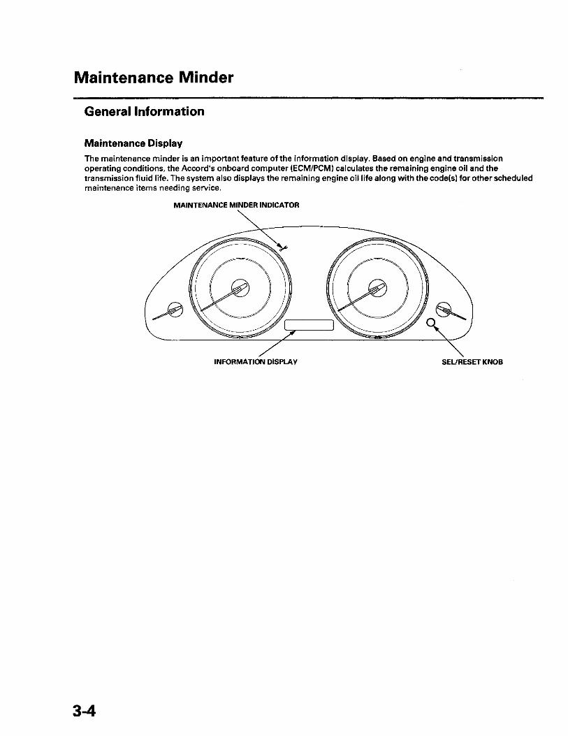
Maintenance Display The maintenance minder is an important feature of the information display. Based on engine and transmission operating conditions, the Accord's onboard computer (ECM/PCM) calculates the remaining engine oil and the transmission fluid life. The system also displays the remaining engine oil life along with the code(s) for other scheduled maintenance items needing service. -
MAINTENANCE MINDER INDICATOR
INFORMATION DISPLAY S E L / R E S E T KNOB
3-4

Service Information
1. The remaining engine oil life on the engine oil life indicator (A) is displayed as a percentage on the information display. To see the current engine oil life, turn the ignition switch to ON (II), then push and release the SEL/RESET knob repeatedly until the engine oil life is displayed.
m o r a
2. When the remaining engine oil life is 15 % to 6 %, the engine oil life indicator will be displayed for several seconds when the ignition switch is ON (II).
The maintenance minder indicator (A) will also come on, and the maintenance item code(s) for other scheduled maintenance items needing service will appear in the information display. • Complete list of maintenance main items (B) (see
page 3-7). • Complete list of maintenance sub items (C) (see
page 3-8).
3. When the remaining engine oil life is 5 % to 1 %, the maintenance message ' 'SERVICE" (A) appears along with the same maintenance item code(s), when the ignition switch is ON (II).
4. When the remaining engine oil life is 0 %, the engine oil life indicator blinks.
This display comes on when the ignition switch is ON (II). At this point, the indicated maintenance must be done as soon as possible.
1
5. If the indicated maintenance is not done, the engine oil life indicator shows a negative mileage, for example "—10" blinking on the display. A negative mileage will display after the vehicle is driven 10 miles (for USA models) or 10 km (for Canada models) after the display begins to blink.
This means that the indicated maintenance item should have been done 10 miles (for USA models) or 10 km (for Canada models) ago.
= 1 0
(cont'd)

Maintenance Minder
General Information (cont'd)
Resetting the Maintenance Information Display
NOTE: * The vehicle must be stopped to reset. • If the required service is done and the display is not
reset or if the display is reset without doing the service, the system will not show the proper maintenance timing. This can lead to serious mechanical problems because there will be no record of when maintenance is needed.
1. Turn the ignition switch ON (II).
2. If oil life is more than 15 %, press the SEL /RESET knob repeatedly until the engine oil life is displayed.
3. Press the S E L / R E S E T knob for about 10 seconds. The engine oil life and the maintenance item code(s) will blink.
NOTE: If you are resetting the display when the engine oil life is more than 15%, make sure the maintenance items requiring service have been done before resetting this display.
4. Press the S E L / R E S E T knob for another 5 seconds. The maintenance item code(s) will disappear and the engine oil life will reset to "100."
Resetting Individual Maintenance Items
1. Connect the Honda Diagnostic System (HDS) to the data link connector (DLC) (see step 2 on page 11-3).
2. Turn the ignition switch to ON (II).
3. Make sure the HDS communicates with the vehicle and the engine control module/powertrain control module (ECM/PCM). If it doesn't communicate, troubleshoot the DLC circuit (see page 11-181).
4. Select GAUGES in the BODY ELECTRICAL with the HDS.
5. Select ADJUSTMENT in the GAUGES with the HDS.
6. Select SERVICE REMINDER in the ADJUSTMENT with the HDS.
7. Select RESET in the SERVICE REMINDER with the HDS.
8. Select the individual maintenance item you wish to reset.
3-6

Maintenance Main Items
If message "SERVICE" does not appear more than 12 months after the display is reset change the engine oil every year.
NOTE: • Independent of the maintenance messages in the smart maintenance display, replace the brake fluid every 3 years. • Inspect idle speed every 160,000 miles (256,000 km). » Adjust the valves during services A, B, 1, 2, or 3 if they are noisy.
Symbol Maintenance Main Items A Replace engine oil (see page 8-11)
Engine oil capacity without oil filter. • '08-09 models: 4.0 L (4.2 US qt) • '10 model: 3.8 L (4.0 US qt)
B Replace engine oil and oil filter (see page 8-12) Engine oil capacity with oil filter.
• '08-09 models: 4.2 L (4.4 US qt) • '10 model: 4.0 L (4.2 US qt) Check front and rear brakes (see page 19-3) • Check pads and discs for wear (thickness), damage, and cracks. • Check calipers for damage, leaks, and tightness of mounting bolts. Check parking brake adjustment (see page 19-8)
Check the number of clicks (7 to 9) when the parking brake lever is pulled with 196 N (20 kgf, 44 Ibf) of force. Inspect tie-rod ends, steering gearbox, and gearbox boots (see page 17-5) • Check steering linkage. • Check boots for damage and leaking grease. • Check fluid lines for damage or leaks. Inspect suspension components (see page 18-3) • Check bolts for tightness. • Check condition of ball joint boots for deterioration and damage. Inspect driveshaft boots (see page 16-4)
Check boots for cracks and boot bands for tightness. Inspect brake hoses and lines including VSA lines (see page 19-46)
Check the master cylinder and VSA modulator-control unit for damage and leakage. Inspect all fluid levels and condition of fluids • Engine coolant (see page 10-6) • Clutch fluid (see page 12-6) • Manual transmission fluid (MTF) (see page 13-5) • Automatic transmission fluid (ATF) (see page 14-191) • Power steering fluid (see page 17-28) • Brake fluid (see page 19-9) • Windshield washer fluid Inspect exhaust system* (see page 9-9)
Check catalytic converter heat shields, exhaust pipes, and muffler for damage, leaks, and tightness. Inspect fuel lines* (see page 11-310) and connections* (see page 11-313)
Check for loose connections, cracks, and deterioration; retighten loose connections and replace damaged parts. NOTE: According to state and federal regulations, failure to do the maintenance items marked with an asterisk (*) will not void the customer's emissions warranties. However, Honda recommends that all maintenance services be done at the recommended interval, to ensure long-term reliability.
3-7

Maintenance Minder
Maintenance Sub Items
Number Maintenance Sub Items 1 Rotate tires, and check tire inflation and condition
Follow the pattern shown in the Owner's Manual. 2 Replace air cleaner element (see page 11-333}
If the vehicle is driven primarily in dusty conditions, replace every 15,000 miles (24,000 km). Replace dust and pollen filter (see page 21-79) • If the vehicle is driven mostly in areas that have high concentrations of dust, pollen, or soot in the air, replace every 15,000
miles (24,000 km). • Replace the filter whenever airflow from the heating and air conditioning system is less than normal. Inspect drive belt (see page 4-29)
Look for cracks and damage, then check the position of the drive belt auto-tensioner indicator. 3 Replace manual transmission fluid (MTF) (see page 13-5)
Capacity: 1.9 L (2.0 US qt); use Honda MTF. Replace automatic transmission fluid (ATF) (see page 14-192) • Capacity: 2.5 L (2.6 US qt); use Honda ATF-Z1. • Driving in mountainous areas at very low vehicle speeds results in higher transmission temperatures. This requires
transmission fluid changes more frequently than recommended by the maintenance minder. If the vehicle is regularly driven under these conditions, change the transmission fluid at 60,000 miles (100,000 km), then every 30,000 miles (48,000 km).
4 Replace spark plugs (see page 4-20) . Use ILZKR7B-11S (NGK) or SXU22HCR11S (DENSO) for all models except PZEV. • Use DILZKR7A11GS (NGK) for PZEV. Inspect valve clearance (cold) • Except PZEV model (see page 6-9) • PZEV model (see page 6-58)
Intake: 0.21 -0 .25 mm (0.008-0.010 in), Exhaust: 0.25-0.29 mm (0.010-0.011 in). 5 Replace engine coolant (see page 10-6)
Capacity (including reservoir/DENSO): • M/T 6.1 L (1.61 US gal) • A/T 6.0 L (1.59 US gal)
Capacity (including reservoir/TRAD): • M/T 6.0 L (1.59 US gal) • ATT 5.9 L (1.56 US gal)
Use Honda Long Life Antifreeze/Coolant Type 2, and add Honda Extreme Cold Weather Antifreeze/Coolant Type 2 in severe cold temperature.
3-8


SUPPLEMENTAL RESTRAINT SYSTEM (SRS) {if engine electrical maintenance is. required)
The Accord SRS includes a driver's airbag in the steering wheel hub, a passenger's airbag in the dashboard above the glove box, seat belt tensioners in the front seat belt retractors, side curtain airbags in the sides of the roof, and side airbags in the front seat-backs. Information necessary to safely service the S R S is Included in this Service Manual. Items marked with an asterisk (*) on the contents page include or are located near S R S components. Servicing, disassembling, or replacing these items requires special precautions and tools, and should be done by an authorized Honda dealer.
• To avoid rendering the SRS inoperative, which could lead to personal injury or death in the event ot a severe frontal or side collision, all SRS service work should be done by an authorized Honda dealer.
• Improper service procedures, including incorrect removal and installation of the S R S , could lead to personal injury caused by unintentional deployment of the airbags, side airbags, and/or side curtain airbags.
• Do not bump or impact the SRS unit, front impact sensors, side impact sensors, or rear safing sensor, especially when the ignition switch is in ON (II), or for at least 3 minutes after the ignition switch Is turned to LOCK (0); otherwise, the system may fail In a collision, or the airbags may deploy.
• S R S electrical connectors are identified by yellow color coding. Related components are located in the steering column, center console, dashboard, dashboard lower cover, In the dashboard above the glove box, In the front seats, in the roof side, and around the floor. Do not use electrical test equipment on these circuits.

Engine Electrical
engine Electrical Special T o o l s . . 4-2
Starting System Component Location Index. . . .4-3 Symptom Troubleshooting
Index. . . . . . — 4-4 Circuit Diagram 4-5 Starter System Circuit
Troubleshooting 4-7 Clutch Interlock Switch T e s t . . . 4-9 Clutch Interlock Switch
R e p l a c e m e n t . . . . . . . . . . . . . . . . . .4-10 Starter Performance Test 4-10 Starter Removal and
Installation — 4-11 Starter Overhaul 4-13
Ignition System Component Location Index — 4-18 Ignition Timing Inspection 4-19 Ignition Coil and Spark Plug
Removal/Installation 4-20 Spark Plug Inspection — 4-20
Charging System Component Location Index. . . .4-22 Symptom Troubleshooting
Index . 4-23 Circuit Diagram . 4-24 Charging System Indicator
Circuit Troubleshooting 4-25 Alternator and Regulator
Circuit Troubleshooting 4-27
Alternator Control Circuit Troubleshooting — 4-28
Drive Belt Inspection 4-29 Drive Belt
Removal/Installation 4-30 Drive Belt Auto-tensioner
Inspection 4-30 Drive Belt Auto-tensioner
Removal/Installation 4-31 Tensioner Pulley
Replacement . .4-32 Alternator Removal and
Installation 4-32 Alternator Overhaul 4-34
Cruise Control Component Location Index. . . .4-39 Symptom Troubleshooting
Index 4-40 Circuit Diagram 4-42 Cruise Control Input Test 4-43
* Cruise Control Combination Switch Test /Replacement. . . 4-45
Clutch Pedal Position Switch Test • . . . 4 -45
Clutch Pedal Position Switch Replacement . . . . .4-46
Engine Mount Control System Component Location Index. . . .4-47 Circuit Diagram 4-48 Troubleshooting 4-49

Engine Electrical
Special Tools
Ref.No. Tool Number Description Qty ® (D
07746-0010300 07749-0010000
Bearing Driver Attachment, 42 x 47 mm Driver Handle, 15 x 135L
1 1
® ©
1-2