Embed Size (px)
Citation preview
Load CellModel 101
FEATURES• 50kgto1000kgrange
• ±0.02%accuracy
• Integralcable
• Costefficient
• One-piece,nickel-platedalloysteelconstruction
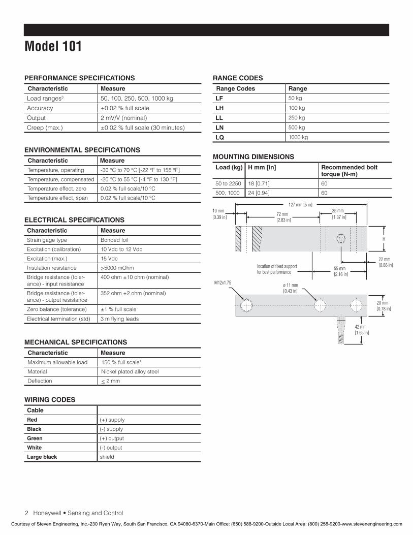
DESCRIPTIONModel101loadcellsisengineeredtomeasurebending
forcesandstillachieveanimpressive0.02%accuracy.Small
dimensionsalloweasyunitintegrationintoexistingsystems.
Model101usesfoilgagesandisavailableforloadrangesfrom
50gramsto1000pounds.
Courtesy of Steven Engineering, Inc.-230 Ryan Way, South San Francisco, CA 94080-6370-Main Office: (650) 588-9200-Outside Local Area: (800) 258-9200-www.stevenengineering.com
2Honeywell•SensingandControl
Model 101
PERFORMANCE SPECIFICATIONS
Characteristic Measure
Loadranges3 50,100,250,500,1000kg
Accuracy ±0.02%fullscale
Output 2mV/V(nominal)
Creep(max.) ±0.02%fullscale(30minutes)
RANGE CODES
Range Codes Range
LF 50kg
LH 100kg
LL 250kg
LN 500kg
LQ 1000kg
ELECTRICAL SPECIFICATIONS
Characteristic Measure
Straingagetype Bondedfoil
Excitation(calibration) 10Vdcto12Vdc
Excitation(max.) 15Vdc
Insulationresistance >5000mOhm
Bridgeresistance(toler-ance)-inputresistance
400ohm±10ohm(nominal)
Bridgeresistance(toler-ance)-outputresistance
352ohm±2ohm(nominal)
Zerobalance(tolerance) ±1%fullscale
Electricaltermination(std) 3mflyingleads
MECHANICAL SPECIFICATIONS
Characteristic Measure
Maximumallowableload 150%fullscale1
Material Nickelplatedalloysteel
Deflection <2mm
WIRING CODES
Cable
Red (+)supply
Black (-)supply
Green (+)output
White (-)output
Large black shield
ENVIRONMENTAL SPECIFICATIONS
Characteristic Measure
Temperature,operating -30°Cto70°C[-22°Fto158°F]
Temperature,compensated -20°Cto55°C[-4°Fto130°F]
Temperatureeffect,zero 0.02%fullscale/10°C
Temperatureeffect,span 0.02%fullscale/10°C
MOUNTING DIMENSIONS
Load (kg) H mm [in] Recommended bolt torque (N-m)
50to2250 18[0.71] 60
500,1000 24[0.94] 60
Courtesy of Steven Engineering, Inc.-230 Ryan Way, South San Francisco, CA 94080-6370-Main Office: (650) 588-9200-Outside Local Area: (800) 258-9200-www.stevenengineering.com
SensingandControl
AutomationandControlSolutions
Honeywell
1985DouglasDriveNorth
GoldenValley,MN55422USA
+1-815-235-6847
www.honeywell.com/sensing
008674-1-EN IL50 GLO May 2008Copyright © 2008 Honeywell International Inc. All rights reserved.
Model 101 Load Cell
NOTES
1. Allowablemaximumloads–maximumloadtobeappliedwithoutdamage2.
2. Withoutdamage-loadingtothislevelwillnotcauseexcessivezeroshiftofperformancedegradation.Theusermustconsiderfatiguelifeforlongtermuseandstructuralintegrity.Allstructurallycriticalapplications(overheadloading,etc.)shouldalwaysbedesignedwithsafetyredundantloadpaths.
3. ThisunitiscalibratedtoMetric(non-Imperial)units.
Warranty. Honeywellwarrantsgoodsofitsmanufactureasbeingfreeofdefectivematerialsandfaultyworkmanship.Honeywell’sstandardproductwarrantyappliesunlessagreedtootherwisebyHoneywellinwriting;pleaserefertoyourorderacknowledgementorconsultyourlocalsalesofficeforspecificwarrantydetails.IfwarrantedgoodsarereturnedtoHoneywellduringtheperiodofcoverage,Honeywellwillrepairorreplace,atitsoption,withoutchargethoseitemsitfindsdefective.The foregoing is buyer’s sole remedy and is in lieu of all warranties, expressed or implied, including those of merchantability and fitness for a particular purpose. In no event shall Honeywell be liable for consequential, special, or indirect damages.
Whileweprovideapplicationassistancepersonally,throughourliteratureandtheHoneywellwebsite,itisuptothecustomertodeterminethesuitabilityoftheproductintheapplication.
Specificationsmaychangewithoutnotice.Theinformationwesupplyisbelievedtobeaccurateandreliableasofthisprinting.However,weassumenoresponsibilityforitsuse.
FormoreinformationaboutSensingandControlproducts,visitwww.honeywell.com/sensingorcall+1-815-235-6847Emailinquiriestoinfo.sc@honeywell.com
WARNINGPERSONAL INJURY•DONOTUSEtheseproductsassafetyoremergencystopdevicesorinanyotherapplicationwherefailureoftheproductcouldresultinpersonalinjury.
Failure to comply with these instructions could result in death or serious injury.
WARNINGMISUSE OF DOCUMENTATION•Theinformationpresentedinthiscatalogueisforreferenceonly.DONOTUSEthisdocumentasproductinstallationinformation.•Completeinstallation,operationandmaintenanceinformationisprovidedintheinstructionssuppliedwitheachproduct.
Failure to comply with these instructions could result in death or serious injury.
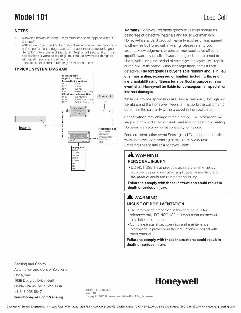
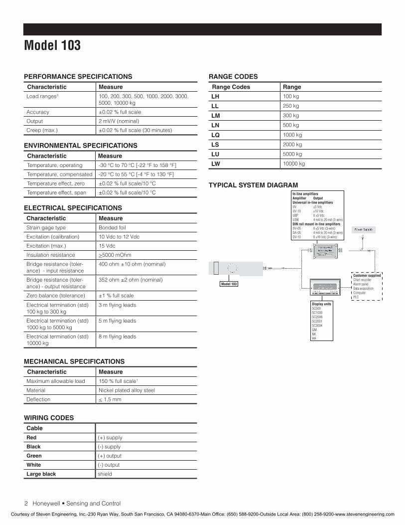
TYPICAL SYSTEM DIAGRAM
Courtesy of Steven Engineering, Inc.-230 Ryan Way, South San Francisco, CA 94080-6370-Main Office: (650) 588-9200-Outside Local Area: (800) 258-9200-www.stevenengineering.com
Load CellModel 102
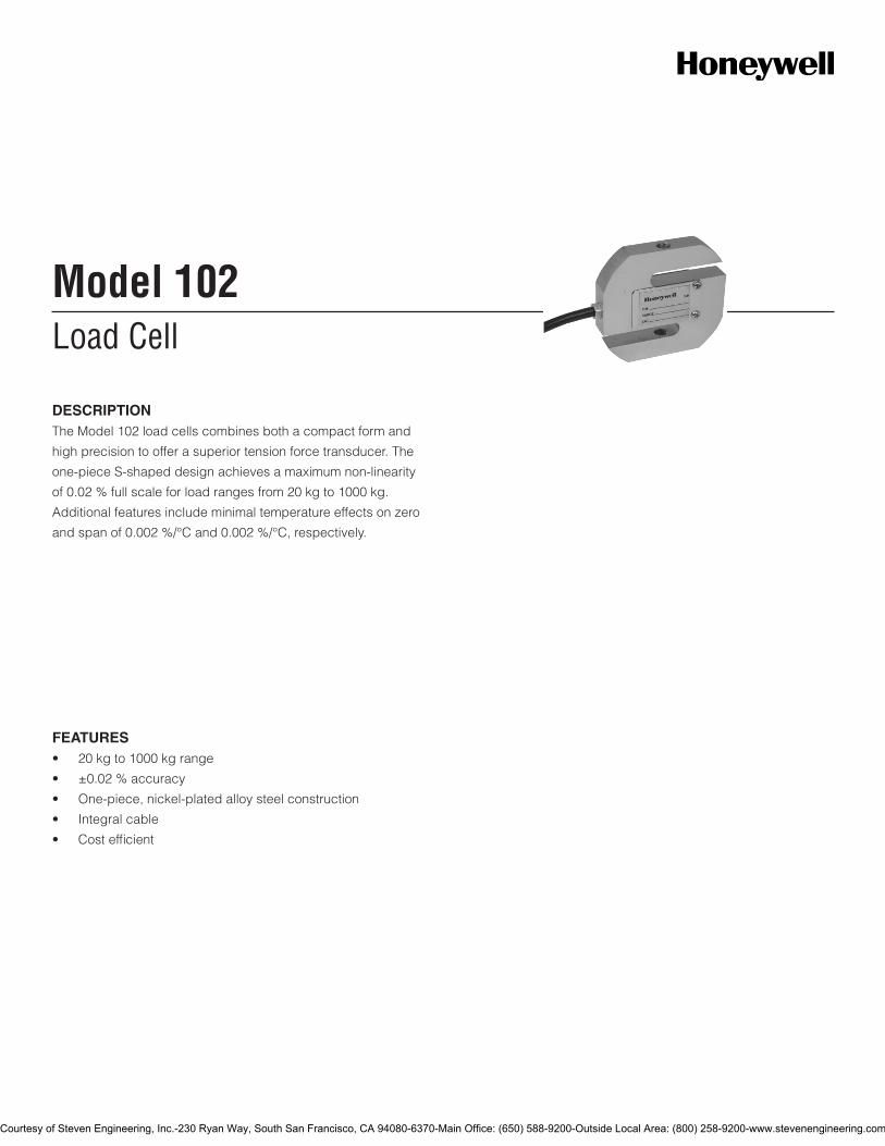
DESCRIPTIONThe Model 102 load cells combines both a compact form and
high precision to offer a superior tension force transducer. The
one-piece S-shaped design achieves a maximum non-linearity
of 0.02 % full scale for load ranges from 20 kg to 1000 kg.
Additional features include minimal temperature effects on zero
and span of 0.002 %/°C and 0.002 %/°C, respectively.
FEATURES• 20kgto1000kgrange
• ±0.02%accuracy
• One-piece,nickel-platedalloysteelconstruction
• Integralcable
• Costefficient
Courtesy of Steven Engineering, Inc.-230 Ryan Way, South San Francisco, CA 94080-6370-Main Office: (650) 588-9200-Outside Local Area: (800) 258-9200-www.stevenengineering.com
2Honeywell•SensingandControl
Model 102
PERFORMANCE SPECIFICATIONS
Characteristic Measure
Load ranges3 20, 50, 100, 200, 300, 500, 1000 kg
Accuracy ±0.02%fullscale
Output 2.0 mV/V
Creep (max.) ±0.02%fullscale(30minutes)
RANGE CODES
Range codes Range
LD 20 kg
LE 30 kg
LF 50 kg
LG 75 kg
LH 100 kg
LJ 150 kg
LK 200 kg
LL 250 kg
LM 300 kg
LN 500 kg
LQ 1000 kg
ELECTRICAL SPECIFICATIONS
Characteristic Measure
Strain gage type Bonded foil
Excitation (acceptable) 10 Vdc to 12 Vdc
Excitation (max.) 15 Vdc
Insulationresistance >5000mOhm
Bridge resistance (toler-ance)-Inputresistance
400ohm±10ohm(nominal)
Bridge resistance (toler-ance)-Outputresistance
352ohm±2ohm(nominal)
Zero balance (tolerance) ±1%fullscale
Electrical termination (std) 3 m [9.84 ft] flying leads
MECHANICAL SPECIFICATIONS
Characteristic Measure
Maximum allowable load 150 full scale1
Material Nickel plated alloy steel or stainless steel
Deflection Less than or equal to 0,5 mm [0.02 in]
WIRING CODES
Cable
Red (+) supply
Black (-) supply
Green (+) output
White (-) output
Large Black Shield
ENVIRONMENTAL SPECIFICATIONS
Characteristic Measure
Temperature, operating -30 °C to 70 °C [-22 °F to 158 °F]
Temperature, compensated -20 °C to 55 °C [-4 °F to 131 °F]
Temperature effect, zero ±0.02%fullscale/10°C
Temperature effect, span ±0.02%fullscale/10°C
Protection class IP67
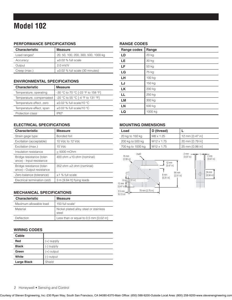
MOUNTING DIMENSIONS
Load D (thread) L
20 kg to 150 kg M8 x 1.25 12 mm [0.47 in]
200 kg to 500 kg M12 x 1.75 20 mm [0.79 in]
700 kg to 1000 kg M12 x 1.75 25 mm [0.98 in]
Courtesy of Steven Engineering, Inc.-230 Ryan Way, South San Francisco, CA 94080-6370-Main Office: (650) 588-9200-Outside Local Area: (800) 258-9200-www.stevenengineering.com
Sensing and Control
Automation and Control Solutions
Honeywell
1985 Douglas Drive North
Golden Valley, MN 55422 USA
+1-815-235-6847
www.honeywell.com/sensing
008662-1-EN IL50 GLO May 2008Copyright © 2008 Honeywell International Inc. All rights reserved.
Model 102 Load Cell
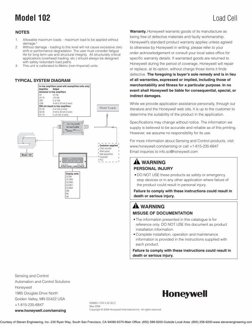
TYPICAL SYSTEM DIAGRAM
NOTES
1. Allowable maximum loads – maximum load to be applied without damage.2
2. Without damage - loading to this level will not cause excessive zero shift or performance degradation. The user must consider fatigue life for long term use and structural integrity. All structurally critical applications (overhead loading, etc.) should always be designed with safety redundant load paths.
3. ThisunitiscalibratedtoMetric(non-Imperial)units.
Warranty. Honeywell warrants goods of its manufacture as being free of defective materials and faulty workmanship. Honeywell’s standard product warranty applies unless agreed to otherwise by Honeywell in writing; please refer to your orderacknowledgementorconsultyourlocalsalesofficeforspecificwarrantydetails.IfwarrantedgoodsarereturnedtoHoneywell during the period of coverage, Honeywell will repair orreplace,atitsoption,withoutchargethoseitemsitfindsdefective. The foregoing is buyer’s sole remedy and is in lieu of all warranties, expressed or implied, including those of merchantability and fitness for a particular purpose. In no event shall Honeywell be liable for consequential, special, or indirect damages.
While we provide application assistance personally, through our literature and the Honeywell web site, it is up to the customer to determine the suitability of the product in the application.
Specificationsmaychangewithoutnotice.Theinformationwesupply is believed to be accurate and reliable as of this printing. However, we assume no responsibility for its use.
For more information about Sensing and Control products, visit www.honeywell.com/sensingorcall+1-815-235-6847Email inquiries to [email protected]
WARNINGPERSONAL INJURY•DONOTUSEtheseproductsassafetyoremergencystopdevicesorinanyotherapplicationwherefailureoftheproductcouldresultinpersonalinjury.
Failure to comply with these instructions could result in death or serious injury.
WARNINGMISUSE OF DOCUMENTATION•Theinformationpresentedinthiscatalogueisforreferenceonly.DONOTUSEthisdocumentasproductinstallationinformation.•Completeinstallation,operationandmaintenanceinformationisprovidedintheinstructionssuppliedwitheachproduct.
Failure to comply with these instructions could result in death or serious injury.
Courtesy of Steven Engineering, Inc.-230 Ryan Way, South San Francisco, CA 94080-6370-Main Office: (650) 588-9200-Outside Local Area: (800) 258-9200-www.stevenengineering.com
Load CellModel 103
FEATURES• Lowcost
• 100kgto10000kgrange
• ±0.02%accuracy
• Integralcable
• Costefficient
• One-piece,nickel-platedalloysteelconstruction
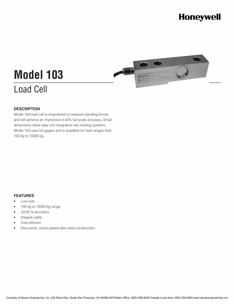
DESCRIPTIONModel103loadcellisengineeredtomeasurebendingforces
andstillachieveanimpressive0.02%fullscaleaccuracy.Small
dimensionsalloweasyunitintegrationintoexistingsystems.
Model103usesfoilgagesandisavailableforloadrangesfrom
100kgto10000kg.
Courtesy of Steven Engineering, Inc.-230 Ryan Way, South San Francisco, CA 94080-6370-Main Office: (650) 588-9200-Outside Local Area: (800) 258-9200-www.stevenengineering.com
2Honeywell•SensingandControl
Model 103
PERFORMANCE SPECIFICATIONS
Characteristic Measure
Loadranges3 100,200,300,500,1000,2000,3000,5000,10000kg
Accuracy ±0.02%fullscale
Output 2mV/V(nominal)
Creep(max.) ±0.02%fullscale(30minutes)
RANGE CODES
Range Codes Range
LH 100kg
LL 250kg
LM 300kg
LN 500kg
LQ 1000kg
LS 2000kg
LU 5000kg
LW 10000kg
ELECTRICAL SPECIFICATIONS
Characteristic Measure
Straingagetype Bondedfoil
Excitation(calibration) 10Vdcto12Vdc
Excitation(max.) 15Vdc
Insulationresistance >5000mOhm
Bridgeresistance(toler-ance)-inputresistance
400ohm±10ohm(nominal)
Bridgeresistance(toler-ance)-outputresistance
352ohm±2ohm(nominal)
Zerobalance(tolerance) ±1%fullscale
Electricaltermination(std)100kgto300kg
3mflyingleads
Electricaltermination(std)1000kgto5000kg
5mflyingleads
Electricaltermination(std)10000kg
8mflyingleads
MECHANICAL SPECIFICATIONS
Characteristic Measure
Maximumallowableload 150%fullscale1
Material Nickelplatedalloysteel
Deflection <1,5mm
WIRING CODES
Cable
Red (+)supply
Black (-)supply
Green (+)output
White (-)output
Large black shield
ENVIRONMENTAL SPECIFICATIONS
Characteristic Measure
Temperature,operating -30°Cto70°C[-22°Fto158°F]
Temperature,compensated -20°Cto55°C[-4°Fto130°F]
Temperatureeffect,zero ±0.02%fullscale/10°C
Temperatureeffect,span ±0.02%fullscale/10°CTYPICAL SYSTEM DIAGRAM
Courtesy of Steven Engineering, Inc.-230 Ryan Way, South San Francisco, CA 94080-6370-Main Office: (650) 588-9200-Outside Local Area: (800) 258-9200-www.stevenengineering.com
Honeywell•SensingandControl3
Load Cell
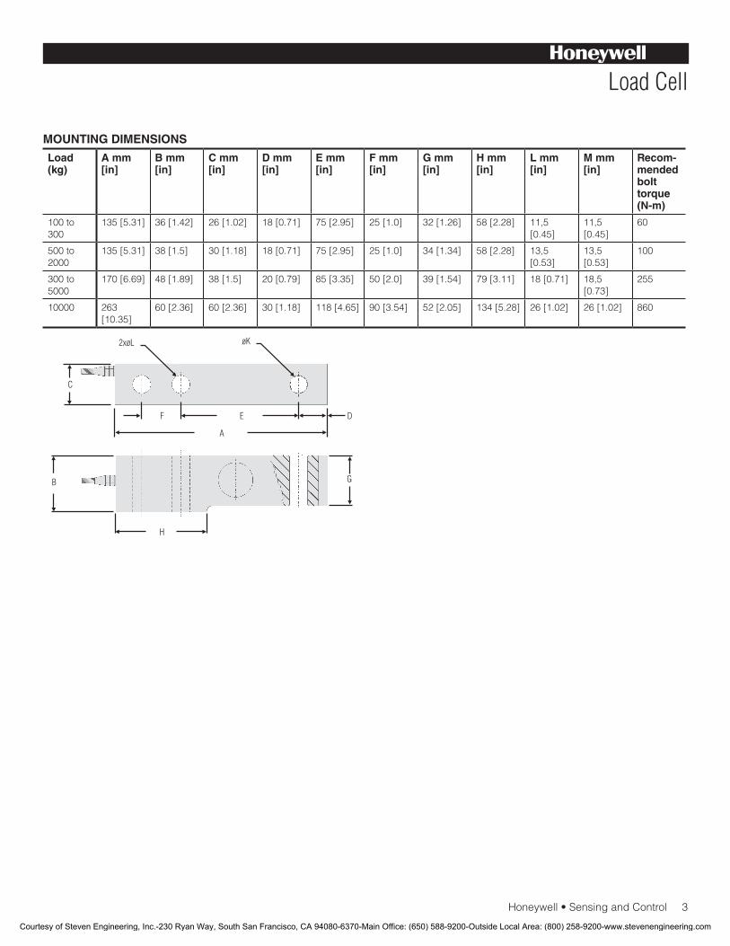
MOUNTING DIMENSIONS
Load (kg)
A mm [in]
B mm [in]
C mm [in]
D mm [in]
E mm [in]
F mm [in]
G mm [in]
H mm [in]
L mm [in]
M mm [in]
Recom-mended bolt torque (N-m)
100to300
135[5.31] 36[1.42] 26[1.02] 18[0.71] 75[2.95] 25[1.0] 32[1.26] 58[2.28] 11,5[0.45]
11,5[0.45]
60
500to2000
135[5.31] 38[1.5] 30[1.18] 18[0.71] 75[2.95] 25[1.0] 34[1.34] 58[2.28] 13,5[0.53]
13,5[0.53]
100
300to5000
170[6.69] 48[1.89] 38[1.5] 20[0.79] 85[3.35] 50[2.0] 39[1.54] 79[3.11] 18[0.71] 18,5[0.73]
255
10000 263[10.35]
60[2.36] 60[2.36] 30[1.18] 118[4.65] 90[3.54] 52[2.05] 134[5.28] 26[1.02] 26[1.02] 860
Courtesy of Steven Engineering, Inc.-230 Ryan Way, South San Francisco, CA 94080-6370-Main Office: (650) 588-9200-Outside Local Area: (800) 258-9200-www.stevenengineering.com

SensingandControl
AutomationandControlSolutions
Honeywell
1985DouglasDriveNorth
GoldenValley,MN55422USA
+1-815-235-6847
www.honeywell.com/sensing
008675-1-EN IL50 GLO May 2008Copyright © 2008 Honeywell International Inc. All rights reserved.
Model 103 Load Cell
NOTES
1. Allowablemaximumloads–maximumloadtobeappliedwithoutdamage2.
2. Withoutdamage-loadingtothislevelwillnotcauseexcessivezeroshiftofperformancedegradation.Theusermustconsiderfatiguelifeforlongtermuseandstructuralintegrity.Allstructurallycriticalapplications(overheadloading,etc.)shouldalwaysbedesignedwithsafetyredundantloadpaths.
3. ThisunitiscalibratedtoMetric(non-Imperial)units.
Warranty. Honeywellwarrantsgoodsofitsmanufactureasbeingfreeofdefectivematerialsandfaultyworkmanship.Honeywell’sstandardproductwarrantyappliesunlessagreedtootherwisebyHoneywellinwriting;pleaserefertoyourorderacknowledgementorconsultyourlocalsalesofficeforspecificwarrantydetails.IfwarrantedgoodsarereturnedtoHoneywellduringtheperiodofcoverage,Honeywellwillrepairorreplace,atitsoption,withoutchargethoseitemsitfindsdefective.The foregoing is buyer’s sole remedy and is in lieu of all warranties, expressed or implied, including those of merchantability and fitness for a particular purpose. In no event shall Honeywell be liable for consequential, special, or indirect damages.
Whileweprovideapplicationassistancepersonally,throughourliteratureandtheHoneywellwebsite,itisuptothecustomertodeterminethesuitabilityoftheproductintheapplication.
Specificationsmaychangewithoutnotice.Theinformationwesupplyisbelievedtobeaccurateandreliableasofthisprinting.However,weassumenoresponsibilityforitsuse.
FormoreinformationaboutSensingandControlproducts,visitwww.honeywell.com/sensingorcall+1-815-235-6847Emailinquiriestoinfo.sc@honeywell.com
WARNINGPERSONAL INJURY
•DONOTUSEtheseproductsassafetyoremergencystopdevicesorinanyotherapplicationwherefailureoftheproductcouldresultinpersonalinjury.
Failure to comply with these instructions could result in death or serious injury.
WARNINGMISUSE OF DOCUMENTATION
•Theinformationpresentedinthiscatalogueisforreferenceonly.DONOTUSEthisdocumentasproductinstallationinformation.•Completeinstallation,operationandmaintenanceinformationisprovidedintheinstructionssuppliedwitheachproduct.
Failure to comply with these instructions could result in death or serious injury.
Courtesy of Steven Engineering, Inc.-230 Ryan Way, South San Francisco, CA 94080-6370-Main Office: (650) 588-9200-Outside Local Area: (800) 258-9200-www.stevenengineering.com
Load CellModel 123
FEATURES• 1000kgto20000kgrange
• ±0.03%accuracy
• Built-inoverloadresistance
• One-piece,nickel-platedalloysteelconstruction
• Integralcable
• Costefficient
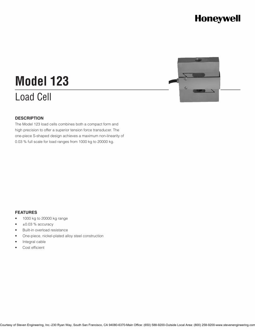
DESCRIPTIONTheModel123loadcellscombinesbothacompactformand
highprecisiontoofferasuperiortensionforcetransducer.The
one-pieceS-shapeddesignachievesamaximumnon-linearityof
0.03%fullscaleforloadrangesfrom1000kgto20000kg.
Courtesy of Steven Engineering, Inc.-230 Ryan Way, South San Francisco, CA 94080-6370-Main Office: (650) 588-9200-Outside Local Area: (800) 258-9200-www.stevenengineering.com
2Honeywell•SensingandControl
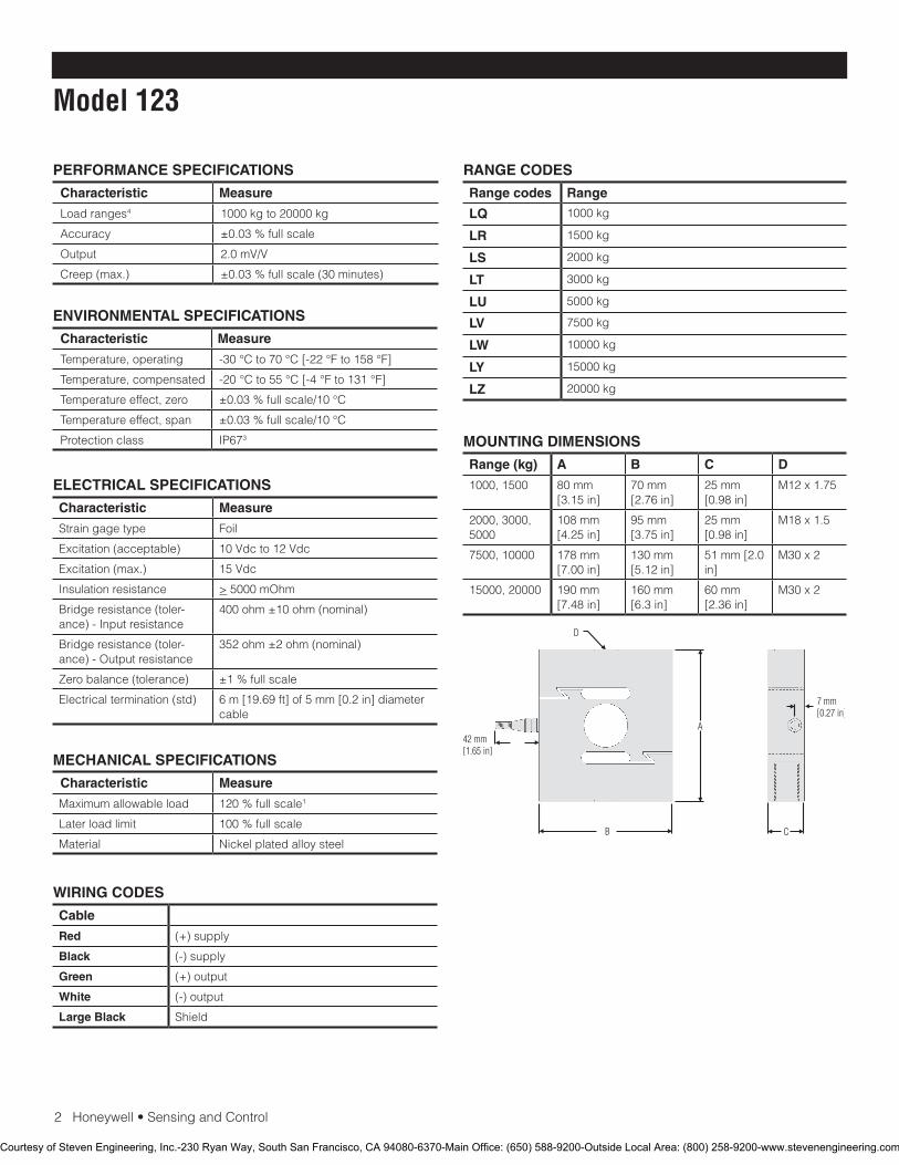
Model 123
PERFORMANCE SPECIFICATIONS
Characteristic Measure
Loadranges4 1000kgto20000kg
Accuracy ±0.03%fullscale
Output 2.0mV/V
Creep(max.) ±0.03%fullscale(30minutes)
RANGE CODES
Range codes Range
LQ 1000kg
LR 1500kg
LS 2000kg
LT 3000kg
LU 5000kg
LV 7500kg
LW 10000kg
LY 15000kg
LZ 20000kg
ELECTRICAL SPECIFICATIONS
Characteristic Measure
Straingagetype Foil
Excitation(acceptable) 10Vdcto12Vdc
Excitation(max.) 15Vdc
Insulationresistance >5000mOhm
Bridgeresistance(toler-ance)-Inputresistance
400ohm±10ohm(nominal)
Bridgeresistance(toler-ance)-Outputresistance
352ohm±2ohm(nominal)
Zerobalance(tolerance) ±1%fullscale
Electricaltermination(std) 6m[19.69ft]of5mm[0.2in]diametercable
MECHANICAL SPECIFICATIONS
Characteristic Measure
Maximumallowableload 120%fullscale1
Laterloadlimit 100%fullscale
Material Nickelplatedalloysteel
WIRING CODES
Cable
Red (+)supply
Black (-)supply
Green (+)output
White (-)output
Large Black Shield
ENVIRONMENTAL SPECIFICATIONS
Characteristic Measure
Temperature,operating -30°Cto70°C[-22°Fto158°F]
Temperature,compensated -20°Cto55°C[-4°Fto131°F]
Temperatureeffect,zero ±0.03%fullscale/10°C
Temperatureeffect,span ±0.03%fullscale/10°C
Protectionclass IP673 MOUNTING DIMENSIONS
Range (kg) A B C D
1000,1500 80mm[3.15in]
70mm[2.76in]
25mm[0.98in]
M12x1.75
2000,3000,5000
108mm[4.25in]
95mm[3.75in]
25mm[0.98in]
M18x1.5
7500,10000 178mm[7.00in]
130mm[5.12in]
51mm[2.0in]
M30x2
15000,20000 190mm[7.48in]
160mm[6.3in]
60mm[2.36in]
M30x2
Courtesy of Steven Engineering, Inc.-230 Ryan Way, South San Francisco, CA 94080-6370-Main Office: (650) 588-9200-Outside Local Area: (800) 258-9200-www.stevenengineering.com
SensingandControl
AutomationandControlSolutions
Honeywell
1985DouglasDriveNorth
GoldenValley,MN55422USA
+1-815-235-6847
www.honeywell.com/sensing
008663-1-EN IL50 GLO May 2008Copyright © 2008 Honeywell International Inc. All rights reserved.
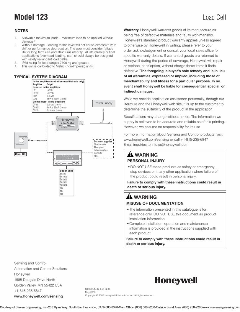
Model 123 Load Cell
TYPICAL SYSTEM DIAGRAM
NOTES
1. Allowablemaximumloads–maximumloadtobeappliedwithoutdamage.2
2. Withoutdamage-loadingtothislevelwillnotcauseexcessivezeroshiftorperformancedegradation.Theusermustconsiderfatiguelifeforlongtermuseandstructuralintegrity.Allstructurallycriticalapplications(overheadloading,etc.)shouldalwaysbedesignedwithsafetyredundantloadpaths.
3. IP68ratingforloadranges7500kgandgreater.4. ThisunitiscalibratedtoMetric(non-Imperial)units.
Warranty. Honeywellwarrantsgoodsofitsmanufactureasbeingfreeofdefectivematerialsandfaultyworkmanship.Honeywell’sstandardproductwarrantyappliesunlessagreedtootherwisebyHoneywellinwriting;pleaserefertoyourorderacknowledgementorconsultyourlocalsalesofficeforspecificwarrantydetails.IfwarrantedgoodsarereturnedtoHoneywellduringtheperiodofcoverage,Honeywellwillrepairorreplace,atitsoption,withoutchargethoseitemsitfindsdefective.The foregoing is buyer’s sole remedy and is in lieu of all warranties, expressed or implied, including those of merchantability and fitness for a particular purpose. In no event shall Honeywell be liable for consequential, special, or indirect damages.
Whileweprovideapplicationassistancepersonally,throughourliteratureandtheHoneywellwebsite,itisuptothecustomertodeterminethesuitabilityoftheproductintheapplication.
Specificationsmaychangewithoutnotice.Theinformationwesupplyisbelievedtobeaccurateandreliableasofthisprinting.However,weassumenoresponsibilityforitsuse.
FormoreinformationaboutSensingandControlproducts,visitwww.honeywell.com/sensingorcall+1-815-235-6847Emailinquiriestoinfo.sc@honeywell.com
WARNINGPERSONAL INJURY•DONOTUSEtheseproductsassafetyoremergencystopdevicesorinanyotherapplicationwherefailureoftheproductcouldresultinpersonalinjury.
Failure to comply with these instructions could result in death or serious injury.
WARNINGMISUSE OF DOCUMENTATION•Theinformationpresentedinthiscatalogueisforreferenceonly.DONOTUSEthisdocumentasproductinstallationinformation.•Completeinstallation,operationandmaintenanceinformationisprovidedintheinstructionssuppliedwitheachproduct.
Failure to comply with these instructions could result in death or serious injury.
Courtesy of Steven Engineering, Inc.-230 Ryan Way, South San Francisco, CA 94080-6370-Main Office: (650) 588-9200-Outside Local Area: (800) 258-9200-www.stevenengineering.com
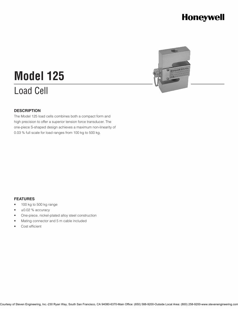
Load CellModel 125
FEATURES• 100kgto500kgrange
• ±0.02%accuracy
• One-piece,nickel-platedalloysteelconstruction
• Matingconnectorand5mcableincluded
• Costefficient
DESCRIPTIONTheModel125loadcellscombinesbothacompactformand
highprecisiontoofferasuperiortensionforcetransducer.The
one-pieceS-shapeddesignachievesamaximumnon-linearityof
0.03%fullscaleforloadrangesfrom100kgto500kg.
Courtesy of Steven Engineering, Inc.-230 Ryan Way, South San Francisco, CA 94080-6370-Main Office: (650) 588-9200-Outside Local Area: (800) 258-9200-www.stevenengineering.com
2Honeywell•SensingandControl
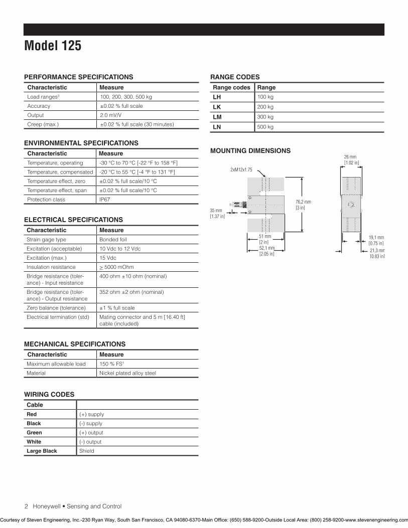
Model 125
PERFORMANCE SPECIFICATIONS
Characteristic Measure
Loadranges3 100,200,300,500kg
Accuracy ±0.02%fullscale
Output 2.0mV/V
Creep(max.) ±0.02%fullscale(30minutes)
RANGE CODES
Range codes Range
LH 100kg
LK 200kg
LM 300kg
LN 500kg
ELECTRICAL SPECIFICATIONS
Characteristic Measure
Straingagetype Bondedfoil
Excitation(acceptable) 10Vdcto12Vdc
Excitation(max.) 15Vdc
Insulationresistance >5000mOhm
Bridgeresistance(toler-ance)-Inputresistance
400ohm±10ohm(nominal)
Bridgeresistance(toler-ance)-Outputresistance
352ohm±2ohm(nominal)
Zerobalance(tolerance) ±1%fullscale
Electricaltermination(std) Matingconnectorand5m[16.40ft]cable(included)
MECHANICAL SPECIFICATIONS
Characteristic Measure
Maximumallowableload 150%FS1
Material Nickelplatedalloysteel
WIRING CODES
Cable
Red (+)supply
Black (-)supply
Green (+)output
White (-)output
Large Black Shield
ENVIRONMENTAL SPECIFICATIONS
Characteristic Measure
Temperature,operating -30°Cto70°C[-22°Fto158°F]
Temperature,compensated -20°Cto55°C[-4°Fto131°F]
Temperatureeffect,zero ±0.02%fullscale/10°C
Temperatureeffect,span ±0.02%fullscale/10°C
Protectionclass IP67
MOUNTING DIMENSIONS
Courtesy of Steven Engineering, Inc.-230 Ryan Way, South San Francisco, CA 94080-6370-Main Office: (650) 588-9200-Outside Local Area: (800) 258-9200-www.stevenengineering.com
SensingandControl
AutomationandControlSolutions
Honeywell
1985DouglasDriveNorth
GoldenValley,MN55422USA
+1-815-235-6847
www.honeywell.com/sensing
008665-1-EN IL50 GLO May 2008Copyright © 2008 Honeywell International Inc. All rights reserved.
Model 125 Load Cell
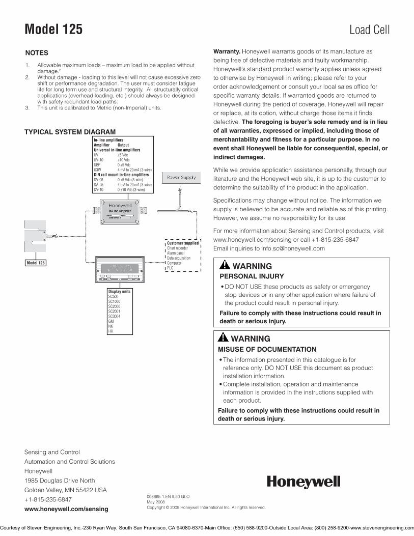
TYPICAL SYSTEM DIAGRAM
NOTES
1. Allowablemaximumloads–maximumloadtobeappliedwithoutdamage.2
2. Withoutdamage-loadingtothislevelwillnotcauseexcessivezeroshiftorperformancedegradation.Theusermustconsiderfatiguelifeforlongtermuseandstructuralintegrity.Allstructurallycriticalapplications(overheadloading,etc.)shouldalwaysbedesignedwithsafetyredundantloadpaths.
3. ThisunitiscalibratedtoMetric(non-Imperial)units.
Warranty. Honeywellwarrantsgoodsofitsmanufactureasbeingfreeofdefectivematerialsandfaultyworkmanship.Honeywell’sstandardproductwarrantyappliesunlessagreedtootherwisebyHoneywellinwriting;pleaserefertoyourorderacknowledgementorconsultyourlocalsalesofficeforspecificwarrantydetails.IfwarrantedgoodsarereturnedtoHoneywellduringtheperiodofcoverage,Honeywellwillrepairorreplace,atitsoption,withoutchargethoseitemsitfindsdefective.The foregoing is buyer’s sole remedy and is in lieu of all warranties, expressed or implied, including those of merchantability and fitness for a particular purpose. In no event shall Honeywell be liable for consequential, special, or indirect damages.
Whileweprovideapplicationassistancepersonally,throughourliteratureandtheHoneywellwebsite,itisuptothecustomertodeterminethesuitabilityoftheproductintheapplication.
Specificationsmaychangewithoutnotice.Theinformationwesupplyisbelievedtobeaccurateandreliableasofthisprinting.However,weassumenoresponsibilityforitsuse.
FormoreinformationaboutSensingandControlproducts,visitwww.honeywell.com/sensingorcall+1-815-235-6847Emailinquiriestoinfo.sc@honeywell.com
WARNINGPERSONAL INJURY•DONOTUSEtheseproductsassafetyoremergencystopdevicesorinanyotherapplicationwherefailureoftheproductcouldresultinpersonalinjury.
Failure to comply with these instructions could result in death or serious injury.
WARNINGMISUSE OF DOCUMENTATION•Theinformationpresentedinthiscatalogueisforreferenceonly.DONOTUSEthisdocumentasproductinstallationinformation.•Completeinstallation,operationandmaintenanceinformationisprovidedintheinstructionssuppliedwitheachproduct.
Failure to comply with these instructions could result in death or serious injury.
Courtesy of Steven Engineering, Inc.-230 Ryan Way, South San Francisco, CA 94080-6370-Main Office: (650) 588-9200-Outside Local Area: (800) 258-9200-www.stevenengineering.com
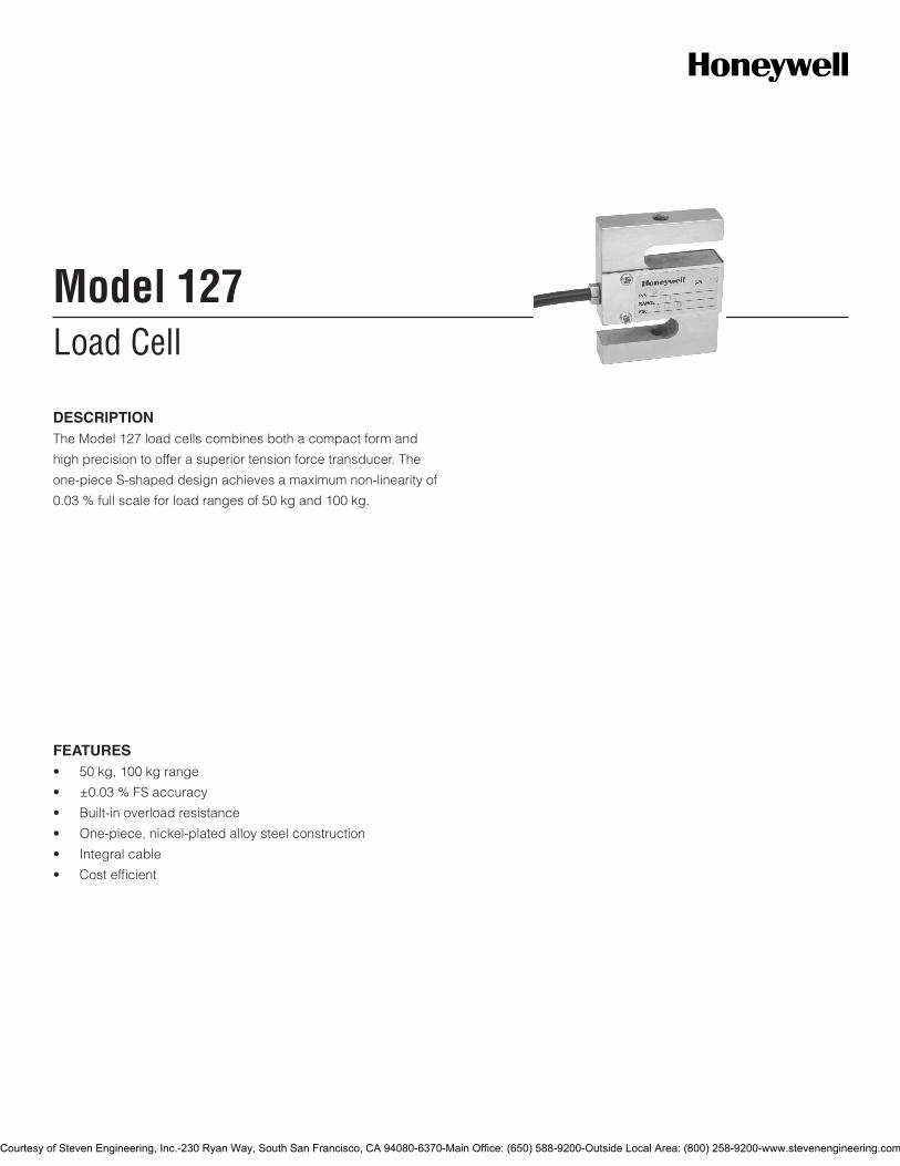
Load CellModel 127
FEATURES• 50kg,100kgrange
• ±0.03%FSaccuracy
• Built-inoverloadresistance
• One-piece,nickel-platedalloysteelconstruction
• Integralcable
• Costefficient
DESCRIPTIONTheModel127loadcellscombinesbothacompactformand
highprecisiontoofferasuperiortensionforcetransducer.The
one-pieceS-shapeddesignachievesamaximumnon-linearityof
0.03%fullscaleforloadrangesof50kgand100kg.
Courtesy of Steven Engineering, Inc.-230 Ryan Way, South San Francisco, CA 94080-6370-Main Office: (650) 588-9200-Outside Local Area: (800) 258-9200-www.stevenengineering.com
2Honeywell•SensingandControl
Model 127
PERFORMANCE SPECIFICATIONS
Characteristic Measure
Loadranges3 50kg,100kg
Accuracy ±0.03%fullscale
Output 3.0mV/V
Creep(max.) ±0.03%fullscale(30minutes)
RANGE CODES
Range codes Range
LF 50kg
LH 100kg
ELECTRICAL SPECIFICATIONS
Characteristic Measure
Straingagetype Bondedfoil
Excitation(acceptable) 10Vdcto12Vdc
Excitation(max.) 15Vdc
Insulationresistance >5000mOhm
Bridgeresistance(toler-ance)-Inputresistance
400ohm±10ohm(nominal)
Bridgeresistance(toler-ance)-Outputresistance
352ohm±2ohm(nominal)
Zerobalance(tolerance) ±1%fullscale
Electricaltermination(std) 5m[16.40ft]flyingleads
MECHANICAL SPECIFICATIONS
Characteristic Measure
Maximumallowableload 150%fullscale1
Material Nickelplatedalloysteel
WIRING CODES
Cable
Red (+)supply
Black (-)supply
Green (+)output
White (-)output
Large Black Shield
ENVIRONMENTAL SPECIFICATIONS
Characteristic Measure
Temperature,operating -30°Cto70°C[-22°Fto158°F]
Temperature,compensated -20°Cto55°C[-4°Fto131°F]
Temperatureeffect,zero ±0.03%fullscale/10°C
Temperatureeffect,span ±0.03%fullscale/10°C
Protectionclass IP67
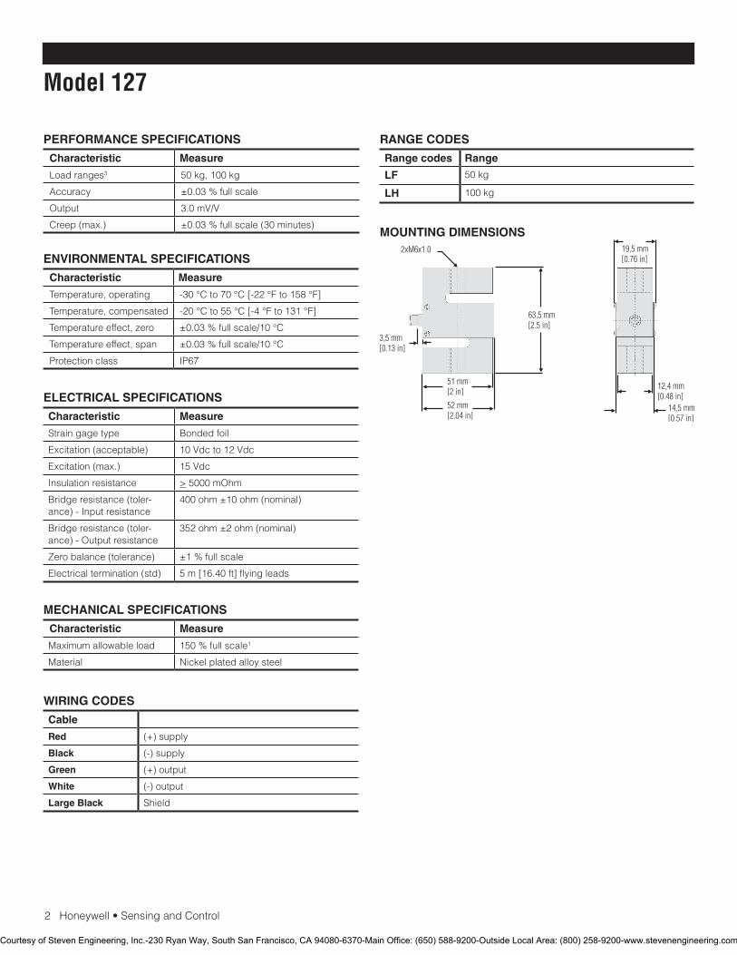
MOUNTING DIMENSIONS
Courtesy of Steven Engineering, Inc.-230 Ryan Way, South San Francisco, CA 94080-6370-Main Office: (650) 588-9200-Outside Local Area: (800) 258-9200-www.stevenengineering.com
SensingandControl
AutomationandControlSolutions
Honeywell
1985DouglasDriveNorth
GoldenValley,MN55422USA
+1-815-235-6847
www.honeywell.com/sensing
008664-1-EN IL50 GLO May 2008Copyright © 2008 Honeywell International Inc. All rights reserved.
Model 127 Load Cell
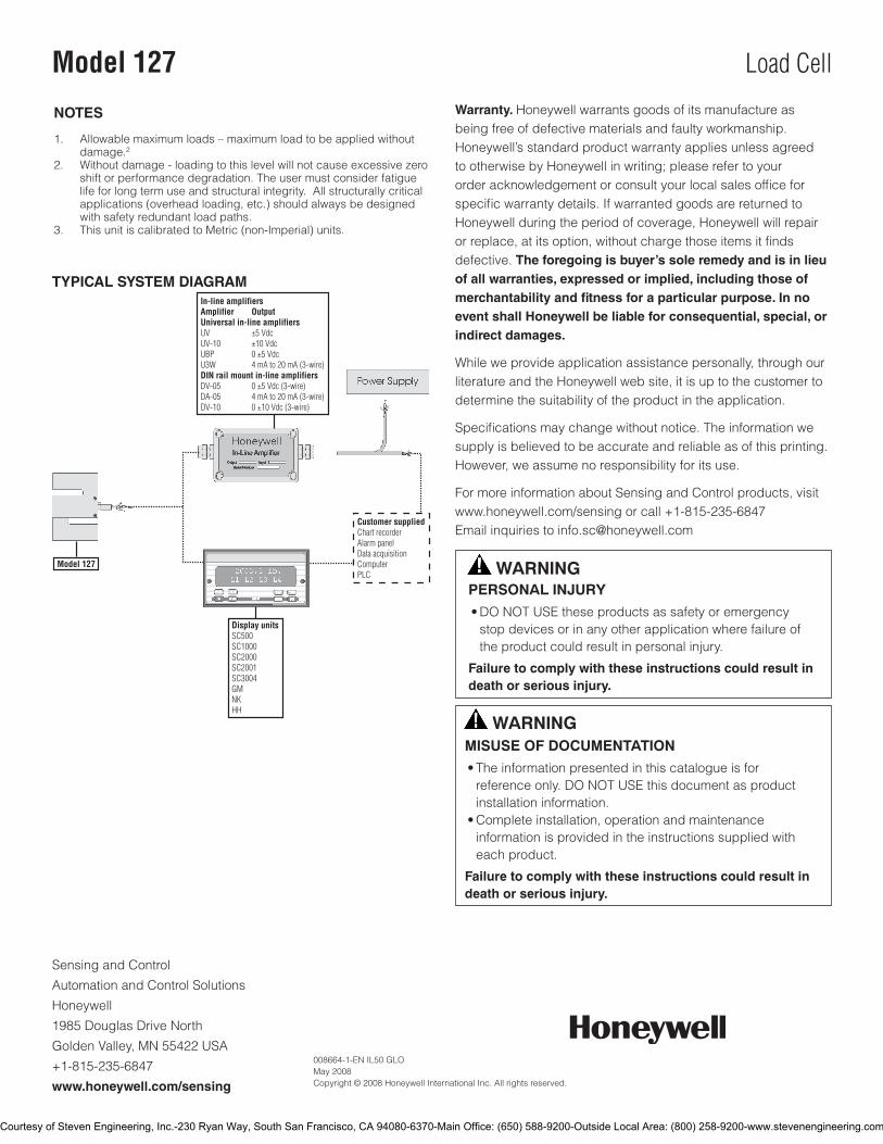
TYPICAL SYSTEM DIAGRAM
NOTES
1. Allowablemaximumloads–maximumloadtobeappliedwithoutdamage.2
2. Withoutdamage-loadingtothislevelwillnotcauseexcessivezeroshiftorperformancedegradation.Theusermustconsiderfatiguelifeforlongtermuseandstructuralintegrity.Allstructurallycriticalapplications(overheadloading,etc.)shouldalwaysbedesignedwithsafetyredundantloadpaths.
3. ThisunitiscalibratedtoMetric(non-Imperial)units.
Warranty. Honeywellwarrantsgoodsofitsmanufactureasbeingfreeofdefectivematerialsandfaultyworkmanship.Honeywell’sstandardproductwarrantyappliesunlessagreedtootherwisebyHoneywellinwriting;pleaserefertoyourorderacknowledgementorconsultyourlocalsalesofficeforspecificwarrantydetails.IfwarrantedgoodsarereturnedtoHoneywellduringtheperiodofcoverage,Honeywellwillrepairorreplace,atitsoption,withoutchargethoseitemsitfindsdefective.The foregoing is buyer’s sole remedy and is in lieu of all warranties, expressed or implied, including those of merchantability and fitness for a particular purpose. In no event shall Honeywell be liable for consequential, special, or indirect damages.
Whileweprovideapplicationassistancepersonally,throughourliteratureandtheHoneywellwebsite,itisuptothecustomertodeterminethesuitabilityoftheproductintheapplication.
Specificationsmaychangewithoutnotice.Theinformationwesupplyisbelievedtobeaccurateandreliableasofthisprinting.However,weassumenoresponsibilityforitsuse.
FormoreinformationaboutSensingandControlproducts,visitwww.honeywell.com/sensingorcall+1-815-235-6847Emailinquiriestoinfo.sc@honeywell.com
WARNINGPERSONAL INJURY•DONOTUSEtheseproductsassafetyoremergencystopdevicesorinanyotherapplicationwherefailureoftheproductcouldresultinpersonalinjury.
Failure to comply with these instructions could result in death or serious injury.
WARNINGMISUSE OF DOCUMENTATION•Theinformationpresentedinthiscatalogueisforreferenceonly.DONOTUSEthisdocumentasproductinstallationinformation.•Completeinstallation,operationandmaintenanceinformationisprovidedintheinstructionssuppliedwitheachproduct.
Failure to comply with these instructions could result in death or serious injury.
Courtesy of Steven Engineering, Inc.-230 Ryan Way, South San Francisco, CA 94080-6370-Main Office: (650) 588-9200-Outside Local Area: (800) 258-9200-www.stevenengineering.com

Load CellModel 129
FEATURES• 1000kgto5000kgrange
• ±0.02%accuracy
• One-piece,nickel-platedalloysteelconstruction
• Integralcable
• Costefficient
DESCRIPTIONTheModel129loadcellscombinesbothacompactformand
highprecisiontoofferasuperiortensionforcetransducer.The
one-pieceS-shapeddesignachievesamaximumnon-linearityof
0.02%fullscaleforloadrangesfrom1000kgto5000kg.
Courtesy of Steven Engineering, Inc.-230 Ryan Way, South San Francisco, CA 94080-6370-Main Office: (650) 588-9200-Outside Local Area: (800) 258-9200-www.stevenengineering.com
2Honeywell•SensingandControl
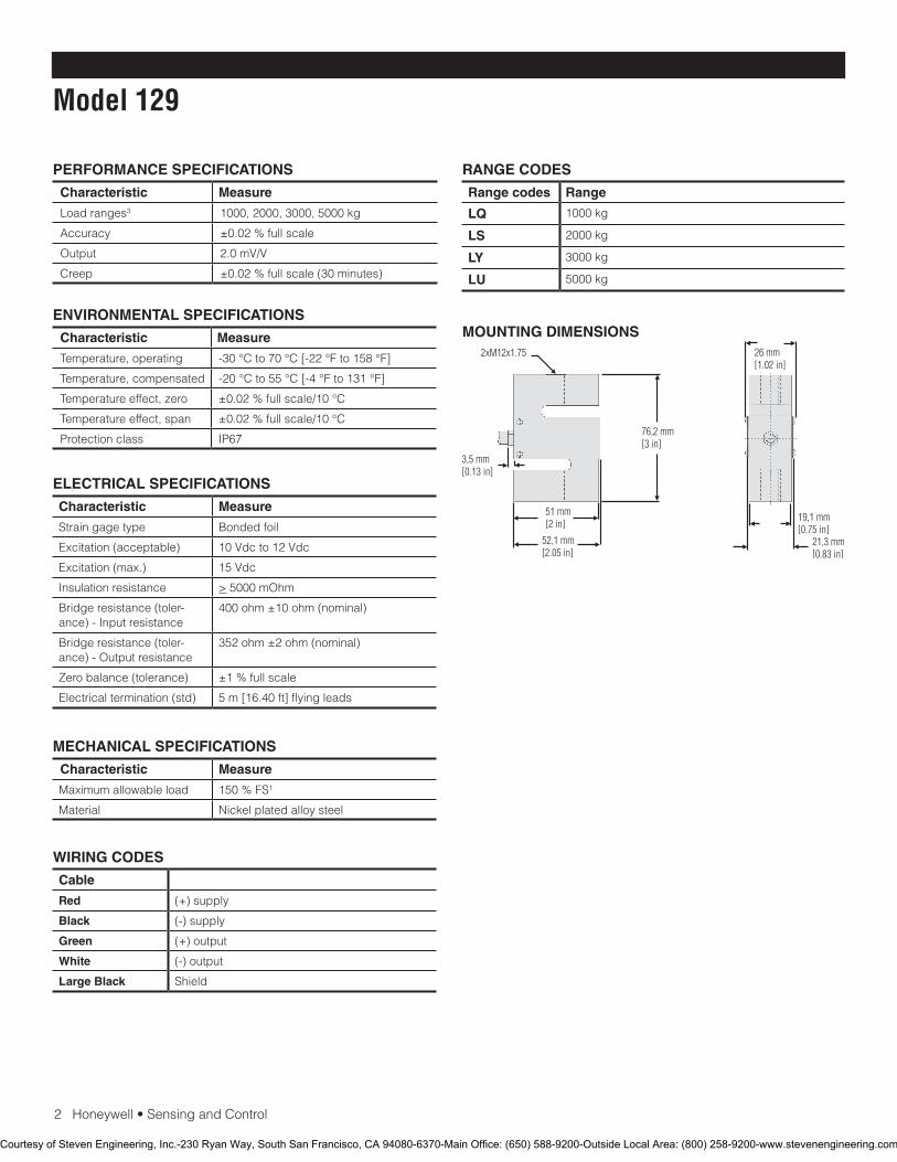
Model 129
PERFORMANCE SPECIFICATIONS
Characteristic Measure
Loadranges3 1000,2000,3000,5000kg
Accuracy ±0.02%fullscale
Output 2.0mV/V
Creep ±0.02%fullscale(30minutes)
RANGE CODES
Range codes Range
LQ 1000kg
LS 2000kg
LY 3000kg
LU 5000kg
ELECTRICAL SPECIFICATIONS
Characteristic Measure
Straingagetype Bondedfoil
Excitation(acceptable) 10Vdcto12Vdc
Excitation(max.) 15Vdc
Insulationresistance >5000mOhm
Bridgeresistance(toler-ance)-Inputresistance
400ohm±10ohm(nominal)
Bridgeresistance(toler-ance)-Outputresistance
352ohm±2ohm(nominal)
Zerobalance(tolerance) ±1%fullscale
Electricaltermination(std) 5m[16.40ft]flyingleads
MECHANICAL SPECIFICATIONS
Characteristic Measure
Maximumallowableload 150%FS1
Material Nickelplatedalloysteel
WIRING CODES
Cable
Red (+)supply
Black (-)supply
Green (+)output
White (-)output
Large Black Shield
ENVIRONMENTAL SPECIFICATIONS
Characteristic Measure
Temperature,operating -30°Cto70°C[-22°Fto158°F]
Temperature,compensated -20°Cto55°C[-4°Fto131°F]
Temperatureeffect,zero ±0.02%fullscale/10°C
Temperatureeffect,span ±0.02%fullscale/10°C
Protectionclass IP67
MOUNTING DIMENSIONS
Courtesy of Steven Engineering, Inc.-230 Ryan Way, South San Francisco, CA 94080-6370-Main Office: (650) 588-9200-Outside Local Area: (800) 258-9200-www.stevenengineering.com
SensingandControl
AutomationandControlSolutions
Honeywell
1985DouglasDriveNorth
GoldenValley,MN55422USA
+1-815-235-6847
www.honeywell.com/sensing
008666-1-EN IL50 GLO May 2008Copyright © 2008 Honeywell International Inc. All rights reserved.
Model 129 Load Cell
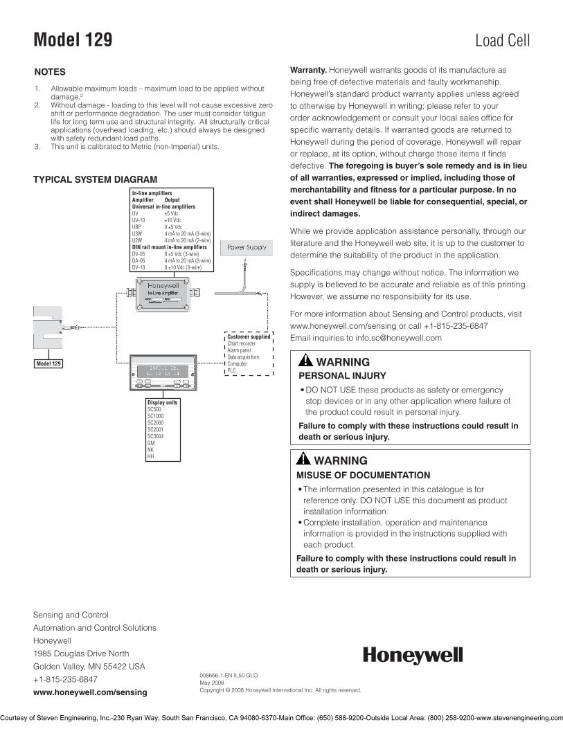
TYPICAL SYSTEM DIAGRAM
NOTES
1. Allowablemaximumloads–maximumloadtobeappliedwithoutdamage.2
2. Withoutdamage-loadingtothislevelwillnotcauseexcessivezeroshiftorperformancedegradation.Theusermustconsiderfatiguelifeforlongtermuseandstructuralintegrity.Allstructurallycriticalapplications(overheadloading,etc.)shouldalwaysbedesignedwithsafetyredundantloadpaths.
3. ThisunitiscalibratedtoMetric(non-Imperial)units.
Warranty. Honeywellwarrantsgoodsofitsmanufactureasbeingfreeofdefectivematerialsandfaultyworkmanship.Honeywell’sstandardproductwarrantyappliesunlessagreedtootherwisebyHoneywellinwriting;pleaserefertoyourorderacknowledgementorconsultyourlocalsalesofficeforspecificwarrantydetails.IfwarrantedgoodsarereturnedtoHoneywellduringtheperiodofcoverage,Honeywellwillrepairorreplace,atitsoption,withoutchargethoseitemsitfindsdefective.The foregoing is buyer’s sole remedy and is in lieu of all warranties, expressed or implied, including those of merchantability and fitness for a particular purpose. In no event shall Honeywell be liable for consequential, special, or indirect damages.
Whileweprovideapplicationassistancepersonally,throughourliteratureandtheHoneywellwebsite,itisuptothecustomertodeterminethesuitabilityoftheproductintheapplication.
Specificationsmaychangewithoutnotice.Theinformationwesupplyisbelievedtobeaccurateandreliableasofthisprinting.However,weassumenoresponsibilityforitsuse.
FormoreinformationaboutSensingandControlproducts,visitwww.honeywell.com/sensingorcall+1-815-235-6847Emailinquiriestoinfo.sc@honeywell.com
WARNINGPERSONAL INJURY•DONOTUSEtheseproductsassafetyoremergencystopdevicesorinanyotherapplicationwherefailureoftheproductcouldresultinpersonalinjury.
Failure to comply with these instructions could result in death or serious injury.
WARNINGMISUSE OF DOCUMENTATION•Theinformationpresentedinthiscatalogueisforreferenceonly.DONOTUSEthisdocumentasproductinstallationinformation.•Completeinstallation,operationandmaintenanceinformationisprovidedintheinstructionssuppliedwitheachproduct.
Failure to comply with these instructions could result in death or serious injury.
Courtesy of Steven Engineering, Inc.-230 Ryan Way, South San Francisco, CA 94080-6370-Main Office: (650) 588-9200-Outside Local Area: (800) 258-9200-www.stevenengineering.com
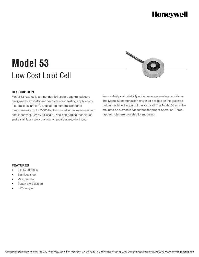
Low Cost Load CellModel 53
DESCRIPTIONModel 53 load cells are bonded foil strain gage transducers
designed for cost efficient production and testing applications
(i.e. press calibration). Engineered compression force
measurements up to 50000 lb., this model achieves a maximum
non-linearity of 0.25 % full scale. Precision gaging techniques
and a stainless steel construction provides excellent long-
term stability and reliability under severe operating conditions.
The Model 53 compression-only load cell has an integral load
button machined as part of the load cell. The Model 53 must be
mounted on a smooth flat surface for proper operation. Three
tapped holes are provided for mounting.
FEATURES• 5lbto50000lb
• Stainlesssteel
• Minifootprint
• Button-styledesign
• mV/Voutput
Courtesy of Steven Engineering, Inc.-230 Ryan Way, South San Francisco, CA 94080-6370-Main Office: (650) 588-9200-Outside Local Area: (800) 258-9200-www.stevenengineering.com
2Honeywell•SensingandControl
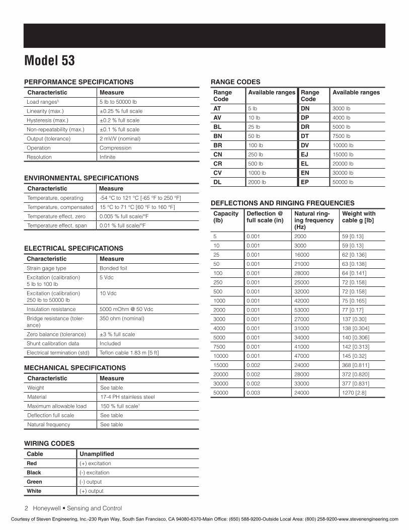
Model 53PERFORMANCE SPECIFICATIONS
Characteristic Measure
Load ranges5 5 lb to 50000 lb
Linearity (max.) ±0.25 % full scale
Hysteresis (max.) ±0.2 % full scale
Non-repeatability (max.) ±0.1 % full scale
Output (tolerance) 2mV/V(nominal)
Operation Compression
Resolution Infinite
ELECTRICAL SPECIFICATIONS
Characteristic Measure
Straingagetype Bondedfoil
Excitation (calibration) 5 lb to 100 lb
5Vdc
Excitation (calibration)250 lb to 50000 lb
10Vdc
Insulation resistance 5000mOhm@50Vdc
Bridgeresistance(toler-ance)
350 ohm (nominal)
Zero balance (tolerance) ±3 % full scale
Shuntcalibrationdata Included
Electrical termination (std) Teflon cable 1.83 m [5 ft]
MECHANICAL SPECIFICATIONS
Characteristic Measure
Weight Seetable
Material 17-4 PH stainless steel
Maximum allowable load 150 % full scale1
Deflection full scale Seetable
Natural frequency Seetable
WIRING CODES
Cable Unamplified
Red (+) excitation
Black (-) excitation
Green (-) output
White (+) output
DEFLECTIONS AND RINGING FREQUENCIES
Capacity (lb)
Deflection @ full scale (in)
Natural ring-ing frequency (Hz)
Weight with cable g [lb]
5 0.001 2000 59 [0.13]
10 0.001 3000 59 [0.13]
25 0.001 16000 62 [0.136]
50 0.001 21000 63 [0.138]
100 0.001 28000 64 [0.141]
250 0.001 25000 72 [0.158]
500 0.001 32000 72 [0.158]
1000 0.001 42000 75 [0.165]
2000 0.001 53000 77 [0.17]
3000 0.001 27000 137 [0.30]
4000 0.001 31000 138 [0.304]
5000 0.001 34000 140 [0.306]
7500 0.001 41000 142 [0.313]
10000 0.001 47000 145 [0.32]
15000 0.002 24000 368 [0.811]
20000 0.002 28000 372 [0.820]
30000 0.002 33000 377 [0.831]
50000 0.003 24000 1270 [2.8]
ENVIRONMENTAL SPECIFICATIONS
Characteristic Measure
Temperature, operating -54°Cto121°C[-65°Fto250°F]
Temperature, compensated 15°Cto71°C[60°Fto160°F]
Temperature effect, zero 0.005%fullscale/°F
Temperature effect, span 0.01%fullscale/°F
RANGE CODES
Range Code
Available ranges Range Code
Available ranges
AT 5 lb DN 3000 lb
AV 10 lb DP 4000 lb
BL 25 lb DR 5000 lb
BN 50 lb DT 7500 lb
BR 100 lb DV 10000 lb
CN 250 lb EJ 15000 lb
CR 500 lb EL 20000 lb
CV 1000 lb EN 30000 lb
DL 2000 lb EP 50000 lb
Courtesy of Steven Engineering, Inc.-230 Ryan Way, South San Francisco, CA 94080-6370-Main Office: (650) 588-9200-Outside Local Area: (800) 258-9200-www.stevenengineering.com

Honeywell•SensingandControl3
Low Cost Load CellMOUNTING DIMENSIONS
Ranges lb D1 mm [in] D2 mm [in] H mm [in] L mm [in] A in B mm [in] G mm [in]
5, 10, 25, 50, 100 25,4 [1.00] 5,33 [0.21] 15,75 [0.62] 1,27 [0.05] #4-40UNC 5,59 [0.22] 19,05 [0.750]
250, 500, 1000, 2000 31,75 [1.25] 8,13 [0.32] 9,91 [0.39] 1,78 [0.07] #6-32UNC 6,35 [0.25] 25,4 [1.000]
3000, 4000, 5000, 7500, 10000
38,1 [1.50] 10,16 [0.40] 16,0 [0.63] 2,03 [0.08] #6-32UNC 6,35 [0.25] 31,75 [1.250]
15000, 20000, 30000 50,8 [2.00] 15,24 [0.60] 25,4 [1.00] 3,05 [0.12] #6-32UNC 6,35 [0.25] 41,28 [1.625]
50000 76,2 [3.00] 19,81 [0.78] 38,1 [1.50] 4,57 [0.18] #6-32UNC 6,35 [0.25] 60,33 [2.375]
OPTION CODESMany range/option combinations are available in our quick-ship and fast-track manufacture pro-grams. Please see http://sensing.honeywell.com/TMsensor-ship for updated listings.
Load ranges
5, 10, 25, 50, 100, 250, 500, 1000, 2000, 3000, 4000, 5000, 7500, 10000, 15000, 20000, 30000, 50000 lb
Tempera-ture com-pensation
1a.60°Fto160°F1b.30°Fto130°F1c.0°Fto185°F1d.-20°Fto130°F1e.-20°Fto200°F1f.70°Fto250°F
1g.70°Fto325°F1h.70°Fto400°F1i.-65°Fto250°F1j.0°Cto50°C1k.-20°Cto85°C1m.-25°Cto110°C
Internal amplifiers
2u.Unamplified,mV/Voutput
Electrical termination
6d.MicrotecDR-4S-4H4-pin6e. Integral cable: Teflon 6f.Integralcable:PVC6g. Integral cable: Neoprene
6h. Integral cable: Silicone
6i. Integral underwa-ter cable3
6v. Phoenix connector on end of cable
Special calibration
9a.10point(5up/5down)20%increments@68°F9b.20point(10up/10down)10%increments@68°F
Shock and vibration
44a.Shockandvibrationresistance
Interfaces 53e.Signaturecalibration6
53t.TEDSIEEE1451.4module4
Courtesy of Steven Engineering, Inc.-230 Ryan Way, South San Francisco, CA 94080-6370-Main Office: (650) 588-9200-Outside Local Area: (800) 258-9200-www.stevenengineering.com
008638-2-EN IL50 GLO January 2010Copyright © 2010 Honeywell International Inc. All rights reserved.
Model 53 Low Cost Load Cell
Sensing and Control
Honeywell
1985 Douglas Drive North
Golden Valley, MN 55422
www.honeywell.com
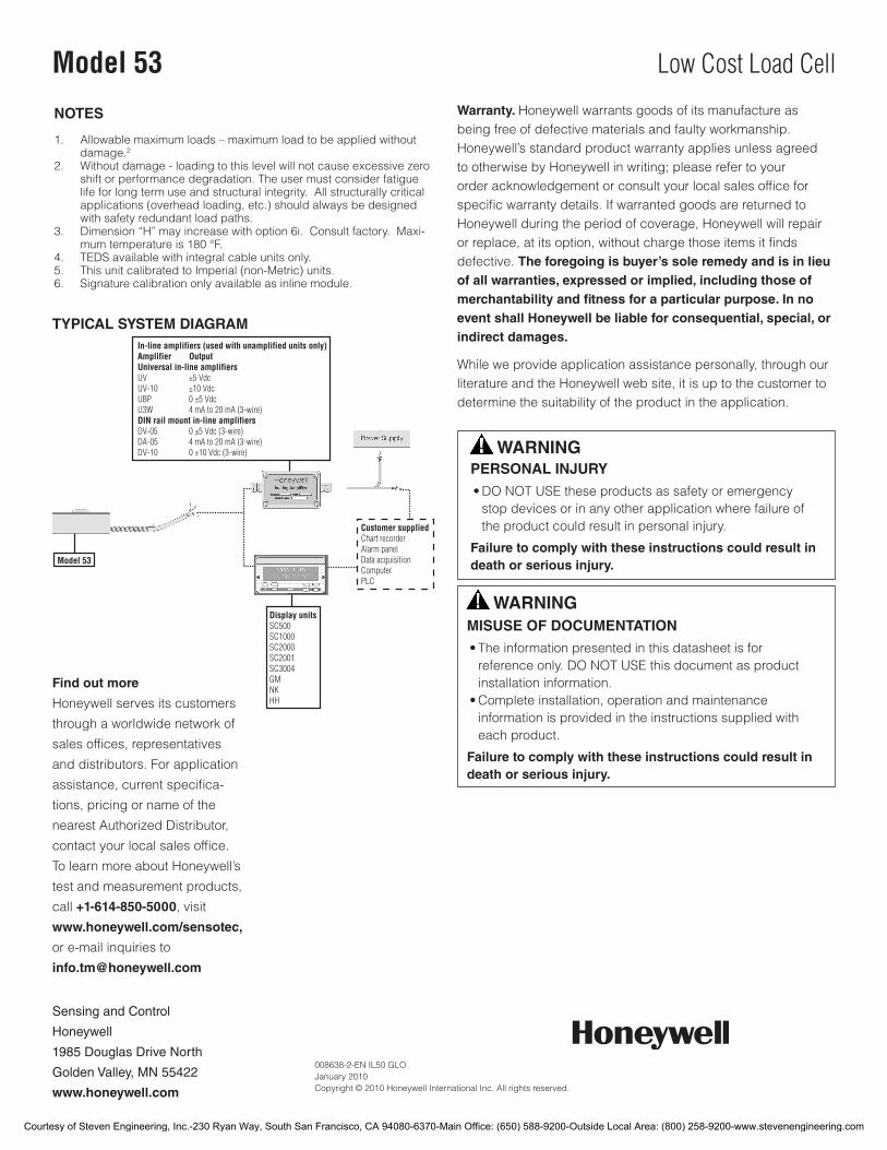
TYPICAL SYSTEM DIAGRAM
NOTES
1. Allowable maximum loads – maximum load to be applied without damage.2
2. Without damage - loading to this level will not cause excessive zero shift or performance degradation. The user must consider fatigue life for long term use and structural integrity. All structurally critical applications (overhead loading, etc.) should always be designed with safety redundant load paths.
3. Dimension“H”mayincreasewithoption6i.Consultfactory.Maxi-mumtemperatureis180°F.
4. TEDSavailablewithintegralcableunitsonly.5. This unit calibrated to Imperial (non-Metric) units.6. Signaturecalibrationonlyavailableasinlinemodule.
Warranty. Honeywell warrants goods of its manufacture as being free of defective materials and faulty workmanship. Honeywell’s standard product warranty applies unless agreed to otherwise by Honeywell in writing; please refer to your order acknowledgement or consult your local sales office for specific warranty details. If warranted goods are returned to Honeywell during the period of coverage, Honeywell will repair or replace, at its option, without charge those items it finds defective. The foregoing is buyer’s sole remedy and is in lieu of all warranties, expressed or implied, including those of merchantability and fitness for a particular purpose. In no event shall Honeywell be liable for consequential, special, or indirect damages.
While we provide application assistance personally, through our literature and the Honeywell web site, it is up to the customer to determine the suitability of the product in the application.
WARNINGPERSONAL INJURY
•DONOTUSEtheseproductsassafetyoremergencystop devices or in any other application where failure of the product could result in personal injury.
Failure to comply with these instructions could result in death or serious injury.
WARNINGMISUSE OF DOCUMENTATION
•Theinformationpresentedinthisdatasheetisforreferenceonly.DONOTUSEthisdocumentasproductinstallation information.
•Completeinstallation,operationandmaintenanceinformation is provided in the instructions supplied with each product.
Failure to comply with these instructions could result in death or serious injury.
Find out more
Honeywell serves its customers
through a worldwide network of
sales offices, representatives
anddistributors.Forapplication
assistance, current specifica-
tions, pricing or name of the
nearest Authorized Distributor,
contact your local sales office.
To learn more about Honeywell’s
test and measurement products,
call +1-614-850-5000, visit
www.honeywell.com/sensotec,
or e-mail inquiries to
Courtesy of Steven Engineering, Inc.-230 Ryan Way, South San Francisco, CA 94080-6370-Main Office: (650) 588-9200-Outside Local Area: (800) 258-9200-www.stevenengineering.com

Precision Low Profile Load CellModel 41
DESCRIPTIONModel 41 is a low profile “pancake” type load cells. These
bonded foil, strain gage load cells are engineered to measure
loads from 5 lb to 500,000 lb. The tension/ compression
Model 41 is designed with the threaded hole running completely
through the center of the cell. Model 41 utilizes two stabilizing
diaphragms, which are welded to the sensing member to
reduce off-center and side-loading effects. It provides high
performance in non-linearity, hysteresis, and repeatability speci-
fications for such applications as tube mills, extruding processes
and weighing. Each unit has a welded construction and can be
hermetically sealed for added durability. Model 41 load cells are
available with optional 0 Vdc to 5 Vdc or 4 mA to 20 mA output.
FEATURES• 0.1%accuracy
• 5lbto500000lb
• mV/Voutput(standard);4mAto20mAand0Vdcto5Vdc
(optional)outputs
• Doublediaphragmdesign
• Intrinsicallysafeavailable(2Noptiononly)16
• CEapproved17
Approved Approved ApprovedIntrinsically safe amp
Courtesy of Steven Engineering, Inc.-230 Ryan Way, South San Francisco, CA 94080-6370-Main Office: (650) 588-9200-Outside Local Area: (800) 258-9200-www.stevenengineering.com
2Honeywell•SensingandControl
Model 41
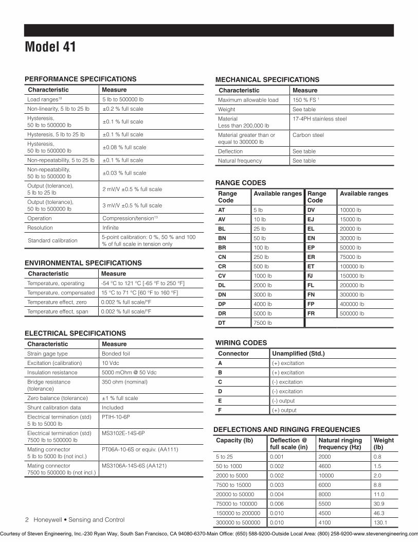
PERFORMANCE SPECIFICATIONS
Characteristic Measure
Load ranges18 5 lb to 500000 lb
Non-linearity,5lbto25lb ±0.2%fullscale
Hysteresis, 50 lb to 500000 lb
±0.1%fullscale
Hysteresis, 5 lb to 25 lb ±0.1%fullscale
Hysteresis, 50 lb to 500000 lb
±0.08%fullscale
Non-repeatability,5to25lb ±0.1%fullscale
Non-repeatability, 50 lb to 500000 lb
±0.03%fullscale
Output(tolerance),5 lb to 25 lb
2mV/V±0.5%fullscale
Output(tolerance),50 lb to 500000 lb
3mV/V±0.5%fullscale
Operation Compression/tension13
Resolution Infinite
Standardcalibration5-pointcalibration:0%,50%and100%offullscaleintensiononly
ENVIRONMENTAL SPECIFICATIONS
Characteristic Measure
Temperature, operating -54°Cto121°C[-65°Fto250°F]
Temperature, compensated 15°Cto71°C[60°Fto160°F]
Temperature effect, zero 0.002%fullscale/°F
Temperature effect, span 0.002%fullscale/°F
ELECTRICAL SPECIFICATIONS
Characteristic Measure
Straingagetype Bonded foil
Excitation(calibration) 10 Vdc
Insulation resistance 5000 mOhm @ 50 Vdc
Bridge resistance (tolerance)
350ohm(nominal)
Zerobalance(tolerance) ±1%fullscale
Shuntcalibrationdata Included
Electricaltermination(std)5 lb to 5000 lb
PTIH-10-6P
Electricaltermination(std)7500 lb to 500000 lb
MS3102E-14S-6P
Mating connector 5lbto5000lb(notincl.)
PT06A-10-6Sorequiv.(AA111)
Mating connector 7500to500000lb(notincl.)
MS3106A-14S-6S(AA121)
MECHANICAL SPECIFICATIONS
Characteristic Measure
Maximum allowable load 150%FS1
Weight Seetable
Material Less than 200,000 lb
17-4PH stainless steel
Material greater than or equalto300000lb
Carbonsteel
Deflection Seetable
Naturalfrequency Seetable
RANGE CODES
Range Code
Available ranges Range Code
Available ranges
AT 5 lb DV 10000 lb
AV 10 lb EJ 15000 lb
BL 25 lb EL 20000 lb
BN 50 lb EN 30000 lb
BR 100 lb EP 50000 lb
CN 250 lb ER 75000 lb
CR 500 lb ET 100000 lb
CV 1000 lb FJ 150000 lb
DL 2000 lb FL 200000 lb
DN 3000 lb FN 300000 lb
DP 4000 lb FP 400000 lb
DR 5000 lb FR 500000 lb
DT 7500 lb
WIRING CODES
Connector Unamplified (Std.)
A (+)excitation
B (+)excitation
C (-)excitation
D (-)excitation
E (-)output
F (+)output
DEFLECTIONS AND RINGING FREQUENCIES
Capacity (lb) Deflection @ full scale (in)
Natural ringing frequency (Hz)
Weight (lb)
5 to 25 0.001 2000 0.8
50 to 1000 0.002 4600 1.5
2000 to 5000 0.002 10000 2.0
7500 to 15000 0.003 6000 8.8
20000 to 50000 0.004 8000 11.0
75000 to 100000 0.006 5500 30.9
150000 to 200000 0.010 4500 46.3
300000 to 500000 0.010 4100 130.1
Courtesy of Steven Engineering, Inc.-230 Ryan Way, South San Francisco, CA 94080-6370-Main Office: (650) 588-9200-Outside Local Area: (800) 258-9200-www.stevenengineering.com
Honeywell•SensingandControl3
Precision Low Profile Load Cell
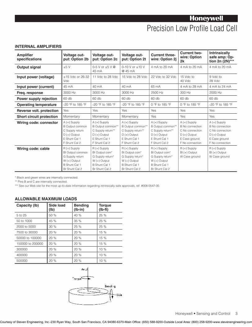
iNTERNAL AMPLIFIERS
Amplifier specifications
Voltage out-put: Option 2b
Voltage out-put: Option 2c
Voltage out-put: Option 2t
Current three-wire: Option 2j
Current two-wire: Option 2k
Intrinsically safe amp: Op-tion 2n (2N)***
Output signal ±5 V 0-5 V or ±5 V @ 45 mA
0-10 V or ±10 V @ 45 mA
4 mA to 20 mA 4 mA to 20 mA 4 mA to 20 mA
Input power (voltage) ±15 Vdc or 26-32 Vdc
11 Vdc to 28 Vdc 15 Vdc to 28 Vdc 22 Vdc to 32 Vdc 15 Vdc to 40 Vdc
9 Vdc to 28 Vdc
Input power (current) 45 mA 40 mA 40 mA 65 mA 4 mA to 28 mA 4 mA to 24 mA
Freq. response 3000 Hz 3000 Hz 3000 Hz 2500 Hz 300 Hz 2000 Hz
Power supply rejection 60 db 60 db 60 db 60 db 60 db 60 db
Operating temperature -20°Fto185°F -20°Fto185°F -20°Fto185°F 0°Fto185°F 0°Fto185°F -20°Fto185°F
Reverse volt. protection Yes Yes Yes Yes Yes Yes
Short circuit protection Momentary Momentary Momentary Yes Yes Yes
Wiring code: connector A(+)SupplyB Output commonCSupplyreturnD(+)OutputEShuntCal1FShuntCal2
A(+)SupplyB Output common**CSupplyreturn**D(+)OutputEShuntCal1FShuntCal2
A(+)SupplyB Output common**CSupplyreturn**D(+)OutputEShuntCal1FShuntCal2
A(+)SupplyB Output common**CSupplyreturn**D(+)OutputEShuntCal1FShuntCal2
A(+)SupplyBNoconnectionCNoconnectionD(+)OutputECasegroundFNoconnection
A(+)SupplyBNoconnectionCNoconnectionD(+)OutputECasegroundFNoconnection
Wiring code: cable R(+)SupplyBl Output commonGSupplyreturnW(+)OutputBShuntCal1BrShuntCal2
R(+)SupplyBl Output com*GSupplyreturn*W(+)OutputBShuntCal1BrShuntCal2
R(+)SupplyBl Output com*GSupplyreturn*W(+)OutputBShuntCal1BrShuntCal2
R(+)SupplyBl Output com*GSupplyreturn*W(+)OutputBShuntCal1BrShuntCal2
R(+)SupplyBl(+)OutputWCaseground
R(+)SupplyBl(+)OutputWCaseground
* Black and green wires are internally connected.**PinsBandCareinternallyconnected.***SeeourWebsiteforthemostup-to-dateinformationregardingintrinsicallysafeapprovals,ref.#008-0547-00.
ALLOWABLE MAXIMUM LOADS
Capacity (lb) Side load (lb)
Bending (lb-in)
Torque (lb-ft)
5 to 25 50% 40% 25%
50 to 1000 45% 35% 25%
2000 to 5000 30% 25% 25%
7500 to 30000 20% 20% 15%
50000 to 100000 20% 20% 15%
150000 to 200000 20% 20% 15%
300000 20% 20% 10%
400000 20% 20% 10%
500000 20% 20% 10%
Courtesy of Steven Engineering, Inc.-230 Ryan Way, South San Francisco, CA 94080-6370-Main Office: (650) 588-9200-Outside Local Area: (800) 258-9200-www.stevenengineering.com
4Honeywell•SensingandControl
Model 41
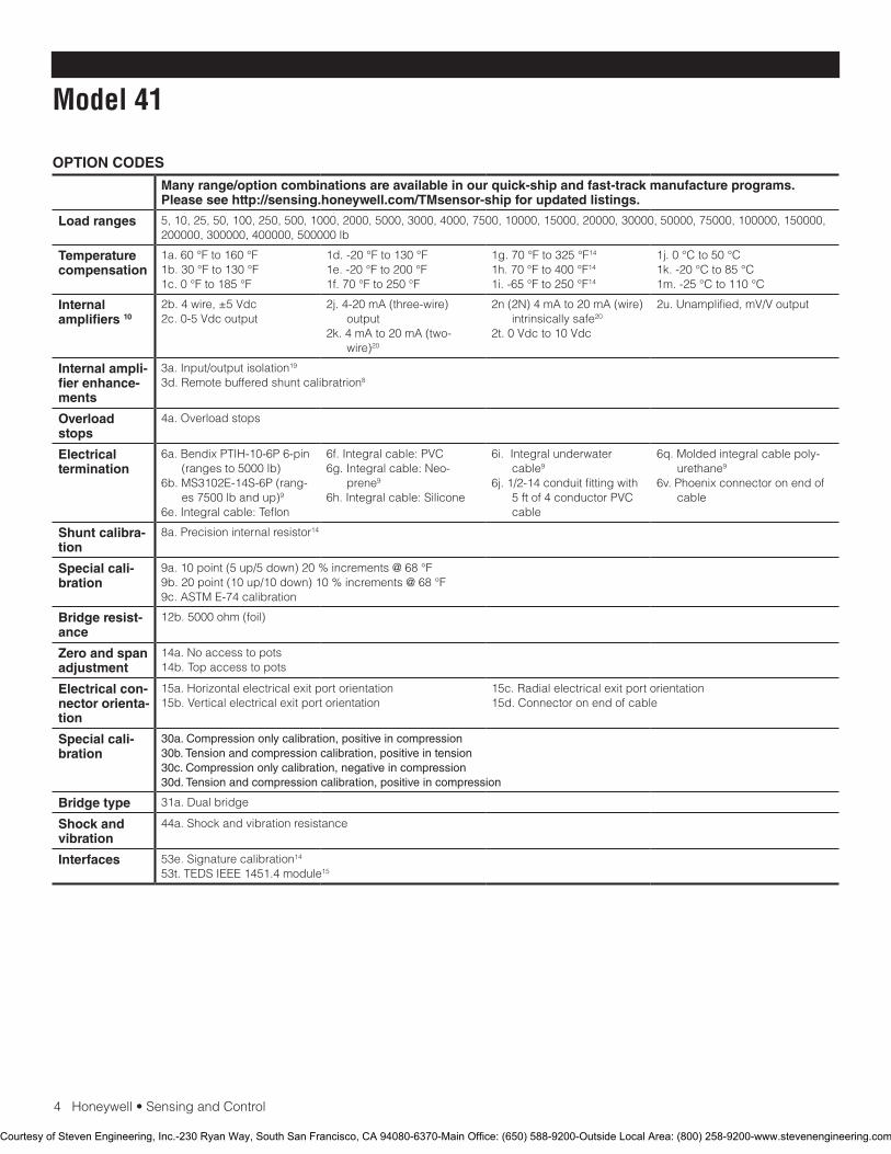
OPTION CODES
Many range/option combinations are available in our quick-ship and fast-track manufacture programs. Please see http://sensing.honeywell.com/TMsensor-ship for updated listings.
Load ranges 5, 10, 25, 50, 100, 250, 500, 1000, 2000, 5000, 3000, 4000, 7500, 10000, 15000, 20000, 30000, 50000, 75000, 100000, 150000, 200000, 300000, 400000, 500000 lb
Temperature compensation
1a.60°Fto160°F1b.30°Fto130°F1c.0°Fto185°F
1d.-20°Fto130°F1e.-20°Fto200°F1f.70°Fto250°F
1g.70°Fto325°F14
1h.70°Fto400°F14
1i.-65°Fto250°F14
1j.0°Cto50°C1k.-20°Cto85°C1m.-25°Cto110°C
Internal amplifiers 10
2b. 4 wire, ±5 Vdc2c. 0-5 Vdc output
2j.4-20mA(three-wire)output
2k.4mAto20mA(two-wire)20
2n(2N)4mAto20mA(wire)intrinsically safe20
2t. 0 Vdc to 10 Vdc
2u. Unamplified, mV/V output
Internal ampli-fier enhance-ments
3a. Input/output isolation19
3d. Remote buffered shunt calibratrion8
Overload stops
4a. Overload stops
Electrical termination
6a. Bendix PTIH-10-6P 6-pin (rangesto5000lb)
6b.MS3102E-14S-6P(rang-es7500lbandup)9
6e.Integralcable:Teflon
6f.Integralcable:PVC6g.Integralcable:Neo-
prene9
6h.Integralcable:Silicone
6i. Integral underwater cable9
6j. 1/2-14 conduit fitting with 5ftof4conductorPVCcable
6q.Moldedintegralcablepoly-urethane9
6v. Phoenix connector on end of cable
Shunt calibra-tion
8a. Precision internal resistor14
Special cali-bration
9a.10point(5up/5down)20%increments@68°F9b.20point(10up/10down)10%increments@68°F9c.ASTME-74calibration
Bridge resist-ance
12b.5000ohm(foil)
Zero and span adjustment
14a.Noaccesstopots14b. Top access to pots
Electrical con-nector orienta-tion
15a. Horizontal electrical exit port orientation15b. Vertical electrical exit port orientation
15c. Radial electrical exit port orientation15d.Connectoronendofcable
Special cali-bration
30a. Compression only calibration, positive in compression30b. Tension and compression calibration, positive in tension30c. Compression only calibration, negative in compression30d. Tension and compression calibration, positive in compression
Bridge type 31a.Dualbridge
Shock and vibration
44a.Shockandvibrationresistance
Interfaces 53e.Signaturecalibration14
53t.TEDSIEEE1451.4module15
Courtesy of Steven Engineering, Inc.-230 Ryan Way, South San Francisco, CA 94080-6370-Main Office: (650) 588-9200-Outside Local Area: (800) 258-9200-www.stevenengineering.com
Honeywell•SensingandControl5
Precision Low Profile Load Cell
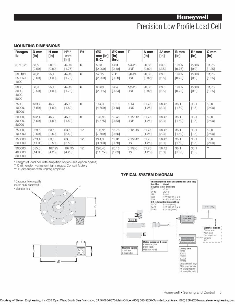
MOUNTING DIMENSIONS
Ranges lb
D mm [in]
H mm [in]
H*** mm [in]
F# ØG mm [in] B.C.
ØK mm [in] thru
T A mm [in]
A* mm [in]
B mm [in]
B* mm [in]
C mm [in]
5, 10, 25 63,5 [2.50]
20,32 [0.80]
44,45 [1.75]
6 50,8 [2.000]
4,83 [0.19]
1/4-28 UNF
20,83 [0.82]
63,5 [2.5]
19,05 [0.75]
22,86 [0.9]
31,75 [1.25]
50, 100, 250, 500, 1000
76,2 [3.00]
25,4 [1.00]
44,45 [1.75]
6 57,15 [2.250]
7,11 [0.28]
3/8-24 UNF
20,83 [0.82]
63,5 [2.5]
19,05 [0.75]
22,86 [0.9]
31,75 [1.25]
2000, 3000, 4000, 5000
88,9 [3.50]
25,4 [1.00]
44,45 [1.75]
6 66,68 [2.625]
8,64 [0.34]
1/2-20 UNF
20,83 [0.82]
63,5 [2.5]
19,05 [0.75]
22,86 [0.9]
31,75 [1.25]
7500, 10000, 15000
139,7 [5.50]
45,7 [1.80]
45,7 [1.80]
8 114,3 [4.500]
10,16 [0.40]
1-14 UNS
31,75 [1.25]
58,42 [2.3]
38,1 [1.50]
38,1 [1.5]
50,8 [2.00}
20000, 30000, 50000
152,4 [6.00]
45,7 [1.80]
45,7 [1.80]
8 123,83 [4.875]
13,46 [0.53]
1 1/2-12 UNF
31,75 [1.25]
58,42 [2.3]
38,1 [1.50]
38,1 [1.5]
50,8 [2.00}
75000, 100000
228,6 [9.00]
63,5 [2.50]
63,5 [2.50]
12 196,85 [7.750]
16,76 [0.66]
2-12UN 31,75 [1.25]
58,42 [2.3]
38,1 [1.50]
38,1 [1.5]
50,8 [2.00}
150000, 200000
279,4 [11.00]
63,5 [2.50]
63,5 [2.50]
12 241,3 [9.500]
19,81 [0.78]
2 1/2-12 UN
31,75 [1.25]
58,42 [2.3]
38,1 [1.50]
38,1 [1.5]
50,8 [2.00}
300000, 400000, 500000
355,6 [14.00]
107,95 [4.25]
107,95 [4.25]
12 298,45 [11.750]
26,16 [1.03]
3 1/2-8 UN
31,75 [1.25]
58,42 [2.3]
38,1 [1.50]
38,1 [1.5]
**
*Lengthofloadcellwithamplifiedoption(seeoptioncodes)**Cdimensionvariesonhighranges.Consultfactory***Hdimensionwith2n(2N)amplifier
TYPICAL SYSTEM DIAGRAM
Courtesy of Steven Engineering, Inc.-230 Ryan Way, South San Francisco, CA 94080-6370-Main Office: (650) 588-9200-Outside Local Area: (800) 258-9200-www.stevenengineering.com
SensingandControl
AutomationandControlSolutions
Honeywell
1985DouglasDriveNorth
GoldenValley,MN55422USA
+1-815-235-6847
www.honeywell.com/sensing
008609-1-EN IL50 GLO May 2008Copyright © 2008 Honeywell International Inc. All rights reserved.
Model 41 Precision Low Profile Load Cell
Warranty. Honeywell warrants goods of its manufacture as being free of defective materials and faulty workmanship. Honeywell’s standard product warranty applies unless agreed tootherwisebyHoneywellinwriting;pleaserefertoyourorder acknowledgement or consult your local sales office for specific warranty details. If warranted goods are returned to Honeywell during the period of coverage, Honeywell will repair or replace, at its option, without charge those items it finds defective. The foregoing is buyer’s sole remedy and is in lieu of all warranties, expressed or implied, including those of merchantability and fitness for a particular purpose. In no event shall Honeywell be liable for consequential, special, or indirect damages.
While we provide application assistance personally, through our literature and the Honeywell web site, it is up to the customer to determine the suitability of the product in the application.
Specificationsmaychangewithoutnotice.Theinformationwesupply is believed to be accurate and reliable as of this printing. However, we assume no responsibility for its use.
FormoreinformationaboutSensingandControlproducts,visitwww.honeywell.com/sensingorcall+1-815-235-6847Emailinquiriestoinfo.sc@honeywell.com
WARNINGPERSONAL INJURY•DONOTUSEtheseproductsassafetyoremergencystopdevicesorinanyotherapplicationwherefailureoftheproductcouldresultinpersonalinjury.
Failure to comply with these instructions could result in death or serious injury.
WARNINGMISUSE OF DOCUMENTATION•Theinformationpresentedinthiscatalogueisforreferenceonly.DONOTUSEthisdocumentasproductinstallationinformation.•Completeinstallation,operationandmaintenanceinformationisprovidedintheinstructionssuppliedwitheachproduct.
Failure to comply with these instructions could result in death or serious injury.
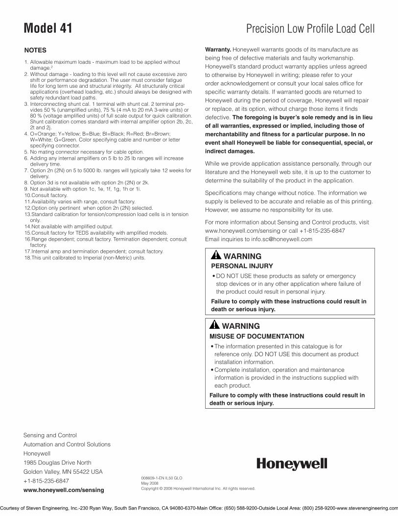
NOTES
1. Allowable maximum loads - maximum load to be applied without damage.2
2. Without damage - loading to this level will not cause excessive zero shift or performance degradation. The user must consider fatigue life for long term use and structural integrity. All structurally critical applications(overheadloading,etc.)shouldalwaysbedesignedwithsafety redundant load paths.
3. Interconnecting shunt cal. 1 terminal with shunt cal. 2 terminal pro-vides50%(unamplifiedunits),75%(4mAto20mA3-wireunits)or80%(voltageamplifiedunits)offullscaleoutputforquickcalibration.Shuntcalibrationcomesstandardwithinternalamplifieroption2b,2c,2t and 2j.
4.O=Orange;Y=Yellow;B=Blue;Bl=Black;R=Red;Br=Brown;W=White;G=Green.Colorspecifyingcableandnumberorletterspecifying connector.
5.Nomatingconnectornecessaryforcableoption.6. Adding any internal amplifiers on 5 lb to 25 lb ranges will increase
delivery time.7.Option2n(2N)on5to5000lb.rangeswilltypicallytake12weeksfor
delivery.8.Option3disnotavailablewithoption2n(2N)or2k.9.Notavailablewithoption1c,1e,1f,1g,1hor1i.10.Consultfactory.11.Availability varies with range, consult factory.12.Optiononlypertinentwhenoption2n(2N)selected.13.Standardcalibrationfortension/compressionloadcellsisintension
only.14.Notavailablewithamplifiedoutput.15.ConsultfactoryforTEDSavailabilitywithamplifiedmodels.16.Rangedependent;consultfactory.Terminationdependent;consult
factory.17.Internalampandterminationdependent;consultfactory.18.ThisunitcalibratedtoImperial(non-Metric)units.
Courtesy of Steven Engineering, Inc.-230 Ryan Way, South San Francisco, CA 94080-6370-Main Office: (650) 588-9200-Outside Local Area: (800) 258-9200-www.stevenengineering.com
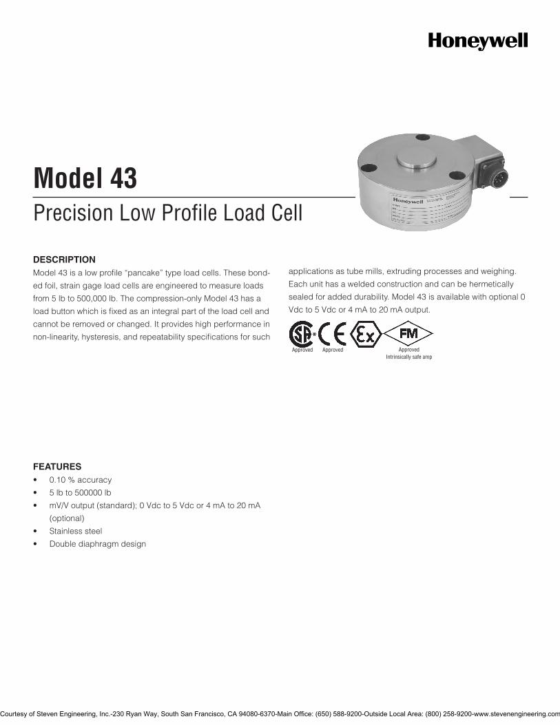
Precision Low Profile Load CellModel 43
DESCRIPTIONModel 43 is a low profile “pancake” type load cells. These bond-
ed foil, strain gage load cells are engineered to measure loads
from 5 lb to 500,000 lb. The compression-only Model 43 has a
load button which is fixed as an integral part of the load cell and
cannot be removed or changed. It provides high performance in
non-linearity, hysteresis, and repeatability specifications for such
applications as tube mills, extruding processes and weighing.
Each unit has a welded construction and can be hermetically
sealed for added durability. Model 43 is available with optional 0
Vdc to 5 Vdc or 4 mA to 20 mA output.
FEATURES• 0.10%accuracy
• 5lbto500000lb
• mV/Voutput(standard);0Vdcto5Vdcor4mAto20mA
(optional)
• Stainlesssteel
• Doublediaphragmdesign
Approved Approved ApprovedIntrinsically safe amp
Courtesy of Steven Engineering, Inc.-230 Ryan Way, South San Francisco, CA 94080-6370-Main Office: (650) 588-9200-Outside Local Area: (800) 258-9200-www.stevenengineering.com
2Honeywell•SensingandControl
Model 43
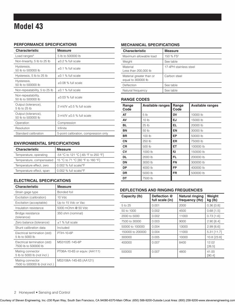
PERFORMANCE SPECIFICATIONS
Characteristic Measure
Load ranges9 5 lb to 500000 lb
Non-linearity, 5 lb to 25 lb ±0.2%fullscale
Hysteresis, 50 lb to 500000 lb
±0.1%fullscale
Hysteresis, 5 lb to 25 lb ±0.1%fullscale
Hysteresis, 50 lb to 500000 lb
±0.08%fullscale
Non-repeatability, 5 to 25 lb ±0.1%fullscale
Non-repeatability, 50 lb to 500000 lb
±0.03%fullscale
Output(tolerance),5 lb to 25 lb
2mV/V±0.5%fullscale
Output(tolerance),50 lb to 500000 lb
3mV/V±0.5%fullscale
Operation Compression
Resolution Infinite
Standardcalibration 5-point calibration, compression only
ENVIRONMENTAL SPECIFICATIONS
Characteristic Measure
Temperature, operating -54°Cto121°C[-65°Fto250°F]
Temperature, compensated 15°Cto71°C[60°Fto160°F]
Temperature effect, zero 0.002%fullscale/°F
Temperature effect, span 0.002%fullscale/°F
ELECTRICAL SPECIFICATIONS
Characteristic Measure
Straingagetype Bonded foil
Excitation(calibration) 10Vdc
Excitation(acceptable) Upto15VdcorVac
Insulation resistance 5000 mOhm @ 50 Vdc
Bridge resistance (tolerance)
350ohm(nominal)
Zerobalance(tolerance) ±1%fullscale
Shuntcalibrationdata Included
Electricaltermination(std)5 lb to 5000 lb
PTIH-10-6P
Electricaltermination(std)7500lbto500000lb
MS3102E-14S-6P
Mating connector 5lbto5000lb(notincl.)
PT06A-10-6Sorequiv.(AA111)
Mating connector 7500to500000lb(notincl.)
MS3106A-14S-6S(AA121)
MECHANICAL SPECIFICATIONS
Characteristic Measure
Maximum allowable load 150%FS2
Weight Seetable
Material Less than 200,000 lb
17-4PHstainlesssteel
Material greater than or equalto300000lb
Carbonsteel
Deflection Seetable
Naturalfrequency Seetable
RANGE CODES
Range Code
Available ranges Range Code
Available ranges
AT 5 lb DV 10000lb
AV 10lb EJ 15000lb
BL 25 lb EL 20000 lb
BN 50 lb EN 30000 lb
BR 100lb EP 50000 lb
CN 250 lb ER 75000lb
CR 500 lb ET 100000lb
CV 1000lb FJ 150000lb
DL 2000 lb FL 200000 lb
DN 3000 lb FN 300000 lb
DP 4000 lb FP 400000 lb
DR 5000 lb FR 500000 lb
DT 7500lb
DEFLECTIONS AND RINGING FREQUENCIES
Capacity (lb) Deflection @ full scale (in)
Natural ringing frequency (Hz)
Weight kg (lb)
5 to 25 0.001 2000 0.36[0.8]
50to1000 0.002 4500 0.68[1.5]
2000 to 5000 0.002 11000 0.73[1.6]
7500to30000 0.003 9000 2.90[6.4]
50000to100000 0.004 13000 2.99[6.6]
150000to200000 0.004 11000 5.31[11.7]
300000 0.005 10000 10.8[23.8]
400000 0.007 8400 12.02[26.5]
500000 0.007 4800 41.00[90.4]
Courtesy of Steven Engineering, Inc.-230 Ryan Way, South San Francisco, CA 94080-6370-Main Office: (650) 588-9200-Outside Local Area: (800) 258-9200-www.stevenengineering.com
Honeywell•SensingandControl3
Precision Low Profile Load Cell
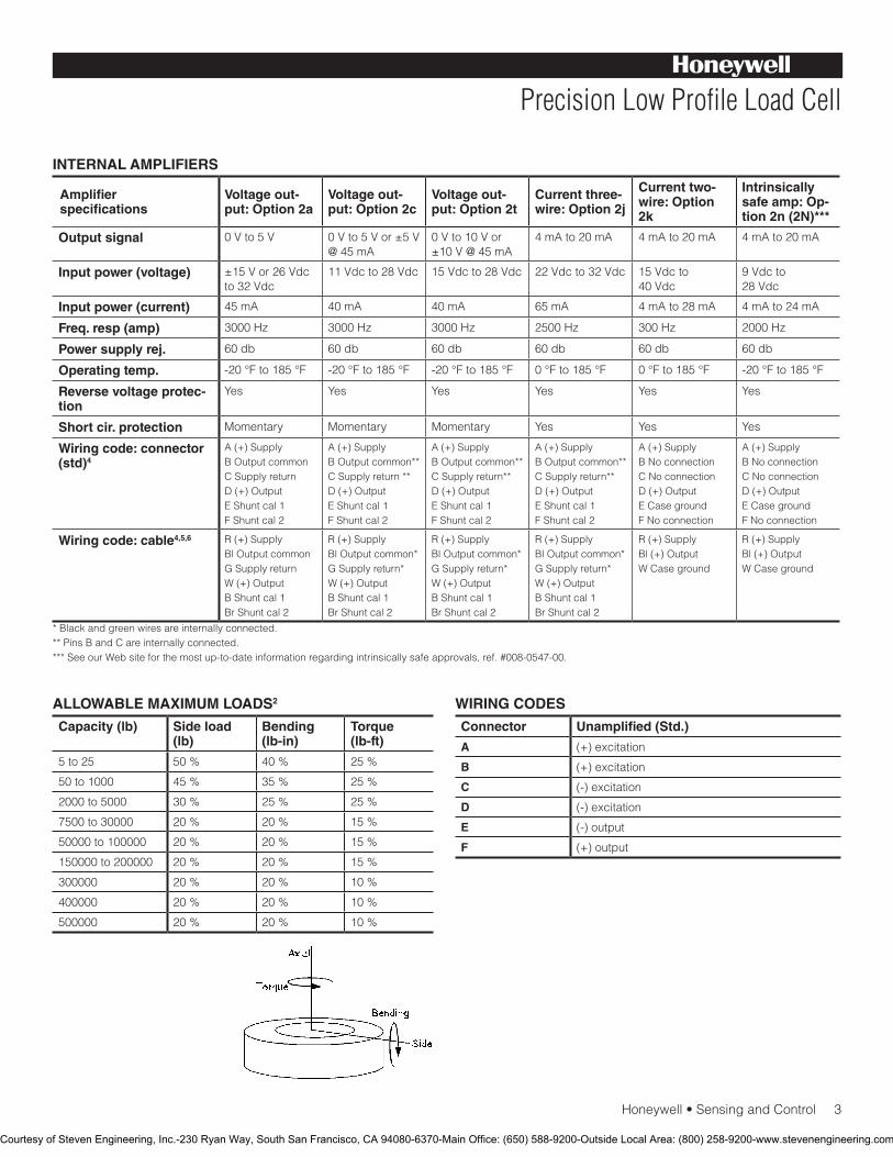
INTERNAL AMPLIFIERS
Amplifier specifications
Voltage out-put: Option 2a
Voltage out-put: Option 2c
Voltage out-put: Option 2t
Current three-wire: Option 2j
Current two-wire: Option 2k
Intrinsically safe amp: Op-tion 2n (2N)***
Output signal 0 V to 5 V 0 V to 5 V or ±5 V @ 45 mA
0Vto10Vor±10V@45mA
4 mA to 20 mA 4 mA to 20 mA 4 mA to 20 mA
Input power (voltage) ±15Vor26Vdcto 32 Vdc
11Vdcto28Vdc 15Vdcto28Vdc 22 Vdc to 32 Vdc 15Vdcto 40 Vdc
9 Vdc to 28 Vdc
Input power (current) 45 mA 40 mA 40 mA 65mA 4 mA to 28 mA 4 mA to 24 mA
Freq. resp (amp) 3000 Hz 3000 Hz 3000 Hz 2500 Hz 300 Hz 2000 Hz
Power supply rej. 60db 60db 60db 60db 60db 60db
Operating temp. -20°Fto185°F -20°Fto185°F -20°Fto185°F 0°Fto185°F 0°Fto185°F -20°Fto185°F
Reverse voltage protec-tion
Yes Yes Yes Yes Yes Yes
Short cir. protection Momentary Momentary Momentary Yes Yes Yes
Wiring code: connector (std)4
A(+)SupplyB Output commonCSupplyreturnD(+)OutputEShuntcal1FShuntcal2
A(+)SupplyB Output common**CSupplyreturn**D(+)OutputEShuntcal1FShuntcal2
A(+)SupplyB Output common**CSupplyreturn**D(+)OutputEShuntcal1FShuntcal2
A(+)SupplyB Output common**CSupplyreturn**D(+)OutputEShuntcal1FShuntcal2
A(+)SupplyB No connectionCNoconnectionD(+)OutputECasegroundFNoconnection
A(+)SupplyB No connectionCNoconnectionD(+)OutputECasegroundFNoconnection
Wiring code: cable4,5,6 R(+)SupplyBl Output commonGSupplyreturnW(+)OutputBShuntcal1BrShuntcal2
R(+)SupplyBl Output common*GSupplyreturn*W(+)OutputBShuntcal1BrShuntcal2
R(+)SupplyBl Output common*GSupplyreturn*W(+)OutputBShuntcal1BrShuntcal2
R(+)SupplyBl Output common*GSupplyreturn*W(+)OutputBShuntcal1BrShuntcal2
R(+)SupplyBl(+)OutputWCaseground
R(+)SupplyBl(+)OutputWCaseground
* Black and green wires are internally connected.**PinsBandCareinternallyconnected.***SeeourWebsiteforthemostup-to-dateinformationregardingintrinsicallysafeapprovals,ref.#008-0547-00.
WIRING CODES
Connector Unamplified (Std.)
A (+)excitation
B (+)excitation
C (-)excitation
D (-)excitation
E (-)output
F (+)output
ALLOWABLE MAXIMUM LOADS2
Capacity (lb) Side load (lb)
Bending (lb-in)
Torque (lb-ft)
5 to 25 50% 40% 25%
50to1000 45% 35% 25%
2000 to 5000 30% 25% 25%
7500to30000 20% 20% 15%
50000to100000 20% 20% 15%
150000to200000 20% 20% 15%
300000 20% 20% 10%
400000 20% 20% 10%
500000 20% 20% 10%
Courtesy of Steven Engineering, Inc.-230 Ryan Way, South San Francisco, CA 94080-6370-Main Office: (650) 588-9200-Outside Local Area: (800) 258-9200-www.stevenengineering.com
4Honeywell•SensingandControl
Model 43
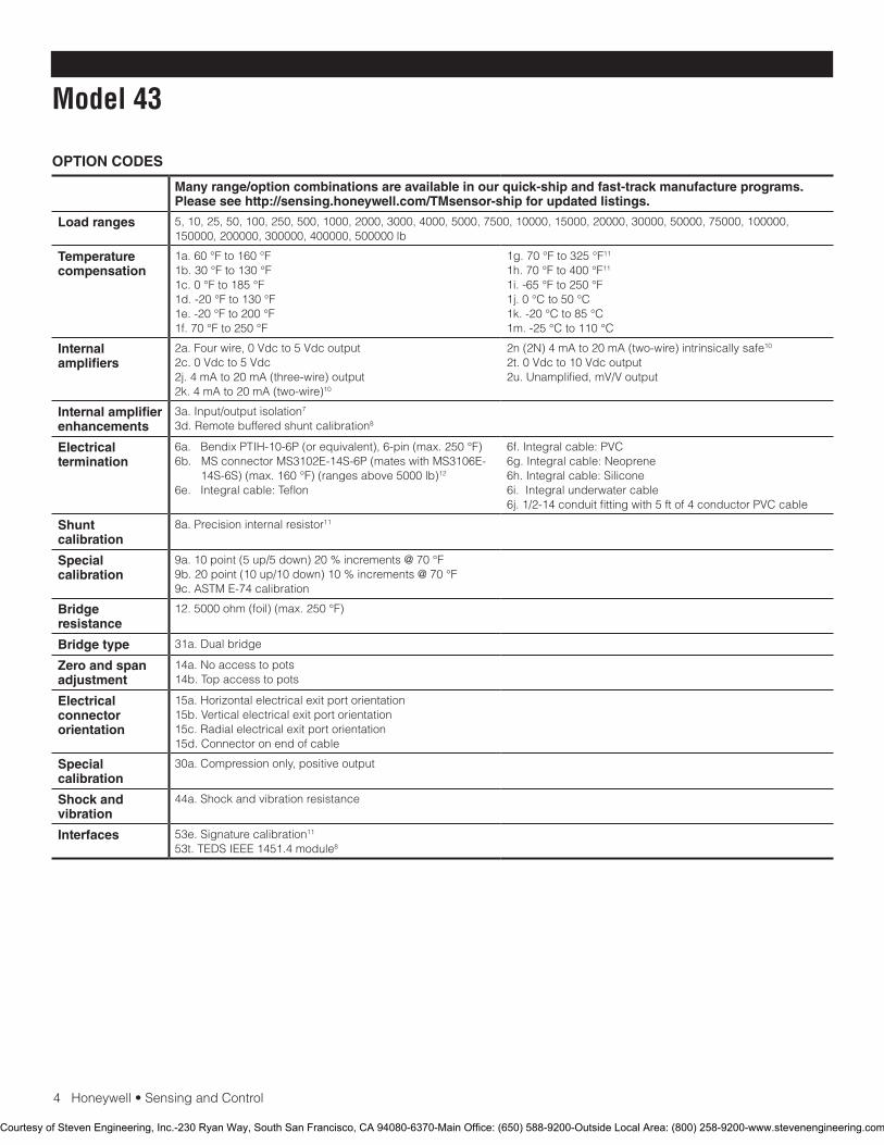
OPTION CODES
Many range/option combinations are available in our quick-ship and fast-track manufacture programs. Please see http://sensing.honeywell.com/TMsensor-ship for updated listings.
Load ranges 5,10,25,50,100,250,500,1000,2000,3000,4000,5000,7500,10000,15000,20000,30000,50000,75000,100000,150000,200000,300000,400000,500000lb
Temperature compensation
1a.60°Fto160°F1b.30°Fto130°F1c.0°Fto185°F1d.-20°Fto130°F1e.-20°Fto200°F1f.70°Fto250°F
1g.70°Fto325°F11
1h.70°Fto400°F11
1i.-65°Fto250°F1j.0°Cto50°C1k.-20°Cto85°C1m.-25°Cto110°C
Internal amplifiers
2a.Fourwire,0Vdcto5Vdcoutput2c. 0 Vdc to 5 Vdc2j.4mAto20mA(three-wire)output2k.4mAto20mA(two-wire)10
2n(2N)4mAto20mA(two-wire)intrinsicallysafe10 2t.0Vdcto10Vdcoutput2u.Unamplified,mV/Voutput
Internal amplifier enhancements
3a.Input/outputisolation7
3d. Remote buffered shunt calibration8
Electrical termination
6a.BendixPTIH-10-6P(orequivalent),6-pin(max.250°F)6b.MSconnectorMS3102E-14S-6P(mateswithMS3106E-
14S-6S)(max.160°F)(rangesabove5000lb)12
6e.Integralcable:Teflon
6f.Integralcable:PVC6g.Integralcable:Neoprene6h.Integralcable:Silicone6i.Integralunderwatercable6j.1/2-14conduitfittingwith5ftof4conductorPVCcable
Shunt calibration
8a. Precision internal resistor11
Special calibration
9a.10point(5up/5down)20%increments@70°F9b.20point(10up/10down)10%increments@70°F9c.ASTME-74calibration
Bridge resistance
12.5000ohm(foil)(max.250°F)
Bridge type 31a.Dualbridge
Zero and span adjustment
14a.Noaccesstopots14b.Topaccesstopots
Electrical connector orientation
15a.Horizontalelectricalexitportorientation15b.Verticalelectricalexitportorientation15c.Radialelectricalexitportorientation15d.Connectoronendofcable
Special calibration
30a.Compressiononly,positiveoutput
Shock and vibration
44a.Shockandvibrationresistance
Interfaces 53e.Signaturecalibration11
53t.TEDSIEEE1451.4module8
Courtesy of Steven Engineering, Inc.-230 Ryan Way, South San Francisco, CA 94080-6370-Main Office: (650) 588-9200-Outside Local Area: (800) 258-9200-www.stevenengineering.com
Honeywell•SensingandControl5
Precision Low Profile Load Cell
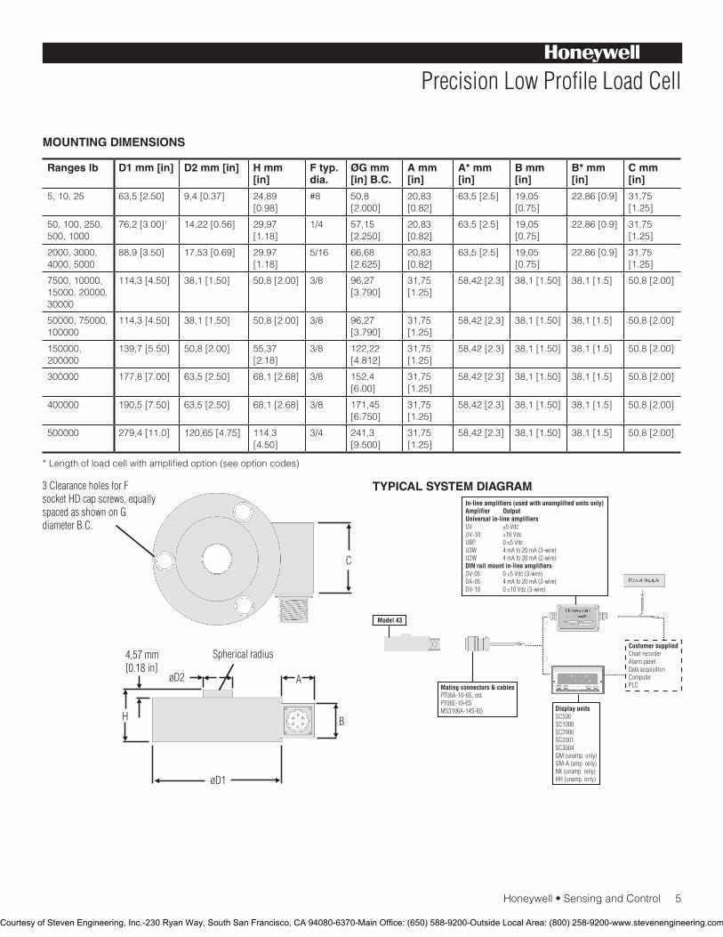
MOUNTING DIMENSIONS
Ranges lb D1 mm [in] D2 mm [in] H mm [in]
F typ. dia.
ØG mm [in] B.C.
A mm [in]
A* mm [in]
B mm [in]
B* mm [in]
C mm [in]
5,10,25 63,5[2.50] 9,4[0.37] 24,89 [0.98]
#8 50,8 [2.000]
20,83 [0.82]
63,5[2.5] 19,05[0.75]
22,86[0.9] 31,75[1.25]
50,100,250,500,1000
76,2[3.00]1 14,22[0.56] 29,97[1.18]
1/4 57,15[2.250]
20,83 [0.82]
63,5[2.5] 19,05[0.75]
22,86[0.9] 31,75[1.25]
2000, 3000, 4000, 5000
88,9[3.50] 17,53[0.69] 29,97[1.18]
5/16 66,68[2.625]
20,83 [0.82]
63,5[2.5] 19,05[0.75]
22,86[0.9] 31,75[1.25]
7500,10000,15000,20000,30000
114,3[4.50] 38,1[1.50] 50,8[2.00] 3/8 96,27[3.790]
31,75[1.25]
58,42[2.3] 38,1[1.50] 38,1[1.5] 50,8[2.00]
50000,75000,100000
114,3[4.50] 38,1[1.50] 50,8[2.00] 3/8 96,27[3.790]
31,75[1.25]
58,42[2.3] 38,1[1.50] 38,1[1.5] 50,8[2.00]
150000,200000
139,7[5.50] 50,8[2.00] 55,37[2.18]
3/8 122,22[4.812]
31,75[1.25]
58,42[2.3] 38,1[1.50] 38,1[1.5] 50,8[2.00]
300000 177,8[7.00] 63,5[2.50] 68,1[2.68] 3/8 152,4[6.00]
31,75[1.25]
58,42[2.3] 38,1[1.50] 38,1[1.5] 50,8[2.00]
400000 190,5[7.50] 63,5[2.50] 68,1[2.68] 3/8 171,45[6.750]
31,75[1.25]
58,42[2.3] 38,1[1.50] 38,1[1.5] 50,8[2.00]
500000 279,4[11.0] 120,65[4.75] 114,3[4.50]
3/4 241,3[9.500]
31,75[1.25]
58,42[2.3] 38,1[1.50] 38,1[1.5] 50,8[2.00]
*Lengthofloadcellwithamplifiedoption(seeoptioncodes)
TYPICAL SYSTEM DIAGRAM
Courtesy of Steven Engineering, Inc.-230 Ryan Way, South San Francisco, CA 94080-6370-Main Office: (650) 588-9200-Outside Local Area: (800) 258-9200-www.stevenengineering.com
SensingandControl
AutomationandControlSolutions
Honeywell
1985DouglasDriveNorth
GoldenValley,MN55422USA
+1-815-235-6847
www.honeywell.com/sensing
008627-1-EN IL50 GLO May 2008Copyright © 2008 Honeywell International Inc. All rights reserved.
Model 43 Precision Low Profile Load Cell
Warranty. Honeywell warrants goods of its manufacture as being free of defective materials and faulty workmanship. Honeywell’s standard product warranty applies unless agreed tootherwisebyHoneywellinwriting;pleaserefertoyourorder acknowledgement or consult your local sales office for specific warranty details. If warranted goods are returned to Honeywell during the period of coverage, Honeywell will repair or replace, at its option, without charge those items it finds defective. The foregoing is buyer’s sole remedy and is in lieu of all warranties, expressed or implied, including those of merchantability and fitness for a particular purpose. In no event shall Honeywell be liable for consequential, special, or indirect damages.
While we provide application assistance personally, through our literature and the Honeywell web site, it is up to the customer to determine the suitability of the product in the application.
Specificationsmaychangewithoutnotice.Theinformationwesupply is believed to be accurate and reliable as of this printing. However, we assume no responsibility for its use.
FormoreinformationaboutSensingandControlproducts,visitwww.honeywell.com/sensingorcall+1-815-235-6847Emailinquiriestoinfo.sc@honeywell.com
WARNINGPERSONAL INJURY•DONOTUSEtheseproductsassafetyoremergencystopdevicesorinanyotherapplicationwherefailureoftheproductcouldresultinpersonalinjury.
Failure to comply with these instructions could result in death or serious injury.
WARNINGMISUSE OF DOCUMENTATION•Theinformationpresentedinthiscatalogueisforreferenceonly.DONOTUSEthisdocumentasproductinstallationinformation.•Completeinstallation,operationandmaintenanceinformationisprovidedintheinstructionssuppliedwitheachproduct.
Failure to comply with these instructions could result in death or serious injury.
NOTES
1. 0.12mm[3.00in]diameterhassixmountingholes.2. Allowable maximum loads - maximum load to be applied without
damage.3
3. Without damage - loading to this level will not cause excessive zero shift or performance degradation. The user must consider fatigue life for long term use and structural integrity. All structurally critical applications(overheadloading,etc.)shouldalwaysbedesignedwith safety redundant load paths.
4. Interconnectingshuntcal.1terminalwithshuntcal.2terminalprovides50%(unamplifiedunits),75%(4mAto20mAthree-wireunits)or80%(voltageamplifiedunits)offullscaleoutputforquickcalibration.Shuntcalibrationcomesstandard
withinternalamplifieroption2a,2b,2c,2tand2j.5. O=Orange;Y=Yellow;B=Blue;Bl=Black; R=Red;Br=Brown;
W=White;G=Green.Colorspecifyingcableandnumberorletter specifying connector 6. Nomatingconnectornecessaryforcableoption.7. Onlyavailablewithoption2aor2c.8. ConsultfactoryforTEDSavailabilitywithamplifiedmodels.9. ThisunitcalibratedtoImperial(non-Metric)units.10. 5000ohmbridgerequired.11. Cannotbeusedwithamplifiedoption.12. Cannotbeusedwithoptions1c,1e,1f,1g,1h,or1i.
Courtesy of Steven Engineering, Inc.-230 Ryan Way, South San Francisco, CA 94080-6370-Main Office: (650) 588-9200-Outside Local Area: (800) 258-9200-www.stevenengineering.com
Precision Low Profile Load CellModel 75
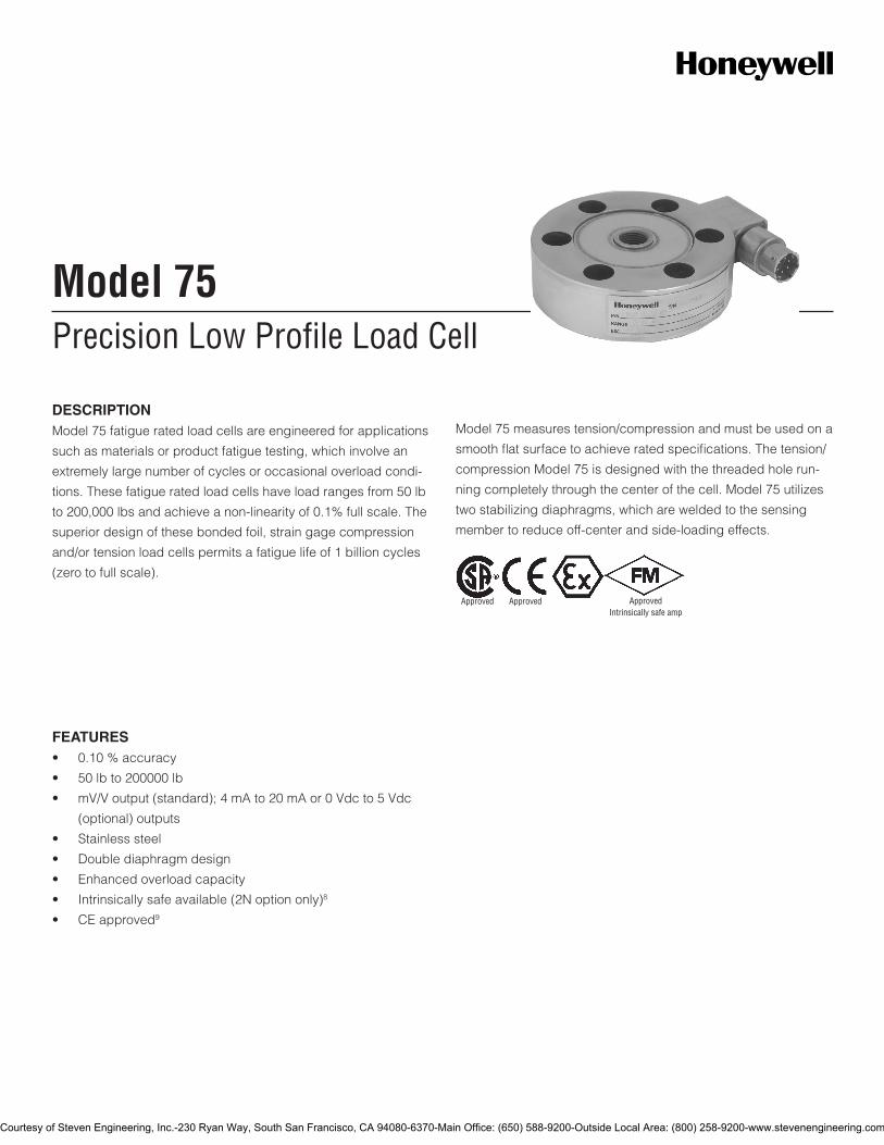
DESCRIPTIONModel 75 fatigue rated load cells are engineered for applications
such as materials or product fatigue testing, which involve an
extremely large number of cycles or occasional overload condi-
tions. These fatigue rated load cells have load ranges from 50 lb
to 200,000 lbs and achieve a non-linearity of 0.1% full scale. The
superior design of these bonded foil, strain gage compression
and/or tension load cells permits a fatigue life of 1 billion cycles
(zero to full scale).
Model 75 measures tension/compression and must be used on a
smooth flat surface to achieve rated specifications. The tension/
compression Model 75 is designed with the threaded hole run-
ning completely through the center of the cell. Model 75 utilizes
two stabilizing diaphragms, which are welded to the sensing
member to reduce off-center and side-loading effects.
FEATURES• 0.10%accuracy
• 50lbto200000lb
• mV/Voutput(standard);4mAto20mAor0Vdcto5Vdc
(optional) outputs
• Stainlesssteel
• Doublediaphragmdesign
• Enhancedoverloadcapacity
• Intrinsicallysafeavailable(2Noptiononly)8
• CEapproved9
Approved Approved ApprovedIntrinsically safe amp
Courtesy of Steven Engineering, Inc.-230 Ryan Way, South San Francisco, CA 94080-6370-Main Office: (650) 588-9200-Outside Local Area: (800) 258-9200-www.stevenengineering.com
2Honeywell•SensingandControl
Model 75
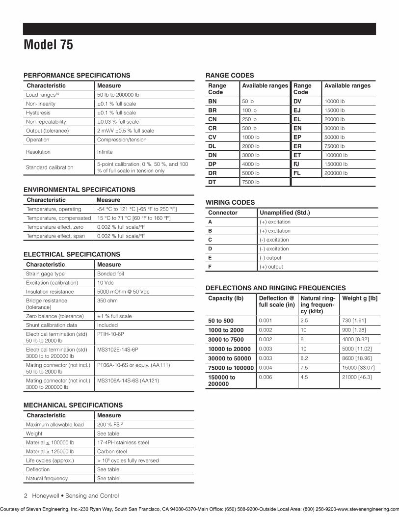
PERFORMANCE SPECIFICATIONS
Characteristic Measure
Load ranges10 50 lb to 200000 lb
Non-linearity ±0.1 % full scale
Hysteresis ±0.1 % full scale
Non-repeatability ±0.03 % full scale
Output (tolerance) 2mV/V±0.5%fullscale
Operation Compression/tension
Resolution Infinite
Standardcalibration5-point calibration, 0 %, 50 %, and 100 % of full scale in tension only
ENVIRONMENTAL SPECIFICATIONS
Characteristic Measure
Temperature, operating -54°Cto121°C[-65°Fto250°F]
Temperature, compensated 15°Cto71°C[60°Fto160°F]
Temperature effect, zero 0.002%fullscale/°F
Temperature effect, span 0.002%fullscale/°F
ELECTRICAL SPECIFICATIONS
Characteristic Measure
Straingagetype Bonded foil
Excitation(calibration) 10Vdc
Insulationresistance 5000mOhm@50Vdc
Bridge resistance (tolerance)
350 ohm
Zero balance (tolerance) ±1 % full scale
Shuntcalibrationdata Included
Electricaltermination(std)50 lb to 2000 lb
PTIH-10-6P
Electricaltermination(std)3000 lb to 200000 lb
MS3102E-14S-6P
Mating connector (not incl.) 50 lb to 2000 lb
PT06A-10-6Sorequiv.(AA111)
Mating connector (not incl.) 3000 to 200000 lb
MS3106A-14S-6S(AA121)
MECHANICAL SPECIFICATIONS
Characteristic Measure
Maximum allowable load 200%FS2
Weight Seetable
Material < 100000 lb 17-4PHstainlesssteel
Material > 125000 lb Carbonsteel
Life cycles (approx.) > 108 cycles fully reversed
Deflection Seetable
Naturalfrequency Seetable
RANGE CODES
Range Code
Available ranges Range Code
Available ranges
BN 50 lb DV 10000 lb
BR 100 lb EJ 15000 lb
CN 250 lb EL 20000 lb
CR 500 lb EN 30000 lb
CV 1000 lb EP 50000 lb
DL 2000 lb ER 75000 lb
DN 3000 lb ET 100000 lb
DP 4000lb FJ 150000 lb
DR 5000 lb FL 200000 lb
DT 7500 lb
WIRING CODES
Connector Unamplified (Std.)
A (+) excitation
B (+) excitation
C (-) excitation
D (-) excitation
E (-) output
F (+) output
DEFLECTIONS AND RINGING FREQUENCIES
Capacity (lb) Deflection @ full scale (in)
Natural ring-ing frequen-cy (kHz)
Weight g [lb]
50 to 500 0.001 2.5 730[1.61]
1000 to 2000 0.002 10 900[1.98]
3000 to 7500 0.002 8 4000[8.82]
10000 to 20000 0.003 10 5000[11.02]
30000 to 50000 0.003 8.2 8600[18.96]
75000 to 100000 0.004 7.5 15000[33.07]
150000 to 200000
0.006 4.5 21000[46.3]
Courtesy of Steven Engineering, Inc.-230 Ryan Way, South San Francisco, CA 94080-6370-Main Office: (650) 588-9200-Outside Local Area: (800) 258-9200-www.stevenengineering.com
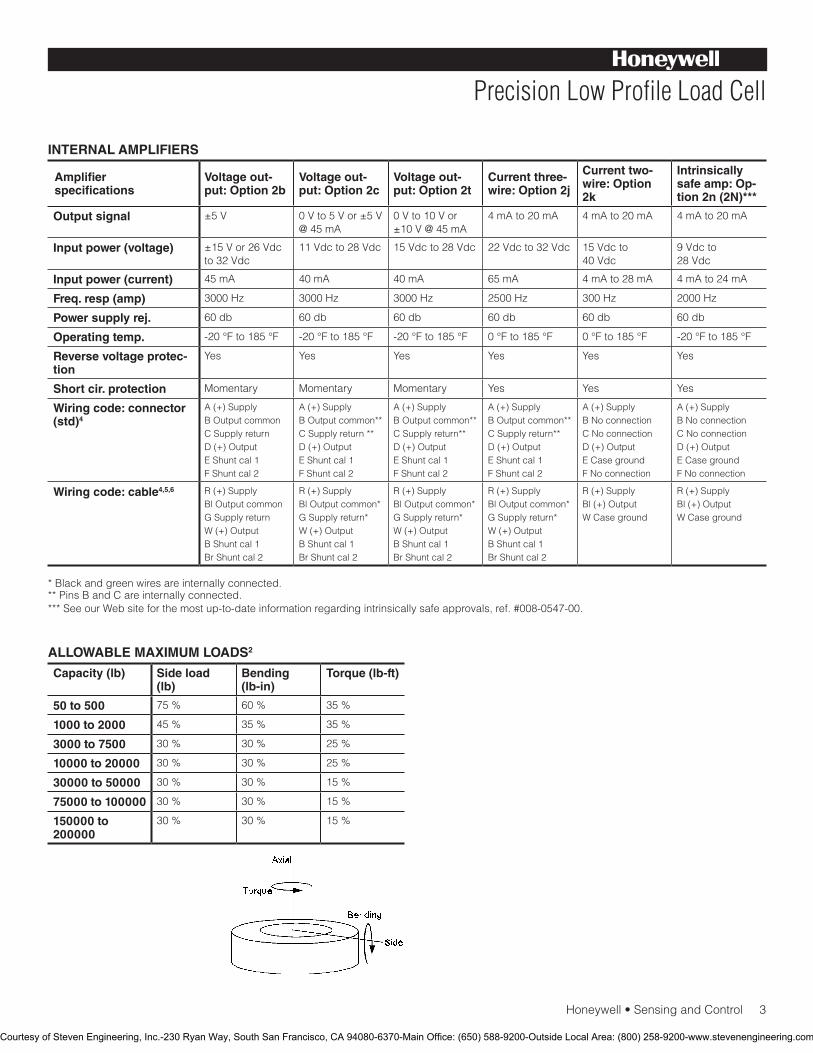
Honeywell•SensingandControl3
Precision Low Profile Load Cell
INTERNAL AMPLIFIERS
Amplifier specifications
Voltage out-put: Option 2b
Voltage out-put: Option 2c
Voltage out-put: Option 2t
Current three-wire: Option 2j
Current two-wire: Option 2k
Intrinsically safe amp: Op-tion 2n (2N)***
Output signal ±5V 0Vto5Vor±5V@45mA
0Vto10Vor±10V@45mA
4mAto20mA 4mAto20mA 4mAto20mA
Input power (voltage) ±15Vor26Vdcto32Vdc
11Vdcto28Vdc 15Vdcto28Vdc 22Vdcto32Vdc 15Vdcto 40Vdc
9Vdcto 28Vdc
Input power (current) 45mA 40mA 40mA 65mA 4mAto28mA 4mAto24mA
Freq. resp (amp) 3000 Hz 3000 Hz 3000 Hz 2500 Hz 300 Hz 2000 Hz
Power supply rej. 60db 60db 60db 60db 60db 60db
Operating temp. -20°Fto185°F -20°Fto185°F -20°Fto185°F 0°Fto185°F 0°Fto185°F -20°Fto185°F
Reverse voltage protec-tion
Yes Yes Yes Yes Yes Yes
Short cir. protection Momentary Momentary Momentary Yes Yes Yes
Wiring code: connector (std)4
A(+)SupplyB Output commonCSupplyreturnD(+)OutputEShuntcal1FShuntcal2
A(+)SupplyB Output common**CSupplyreturn**D(+)OutputEShuntcal1FShuntcal2
A(+)SupplyB Output common**CSupplyreturn**D(+)OutputEShuntcal1FShuntcal2
A(+)SupplyB Output common**CSupplyreturn**D(+)OutputEShuntcal1FShuntcal2
A(+)SupplyBNoconnectionCNoconnectionD(+)OutputECasegroundFNoconnection
A(+)SupplyBNoconnectionCNoconnectionD(+)OutputECasegroundFNoconnection
Wiring code: cable4,5,6 R(+)SupplyBl Output commonGSupplyreturnW (+) OutputBShuntcal1BrShuntcal2
R(+)SupplyBl Output common*GSupplyreturn*W (+) OutputBShuntcal1BrShuntcal2
R(+)SupplyBl Output common*GSupplyreturn*W (+) OutputBShuntcal1BrShuntcal2
R(+)SupplyBl Output common*GSupplyreturn*W (+) OutputBShuntcal1BrShuntcal2
R(+)SupplyBl (+) OutputWCaseground
R(+)SupplyBl (+) OutputWCaseground
* Black and green wires are internally connected.**PinsBandCareinternallyconnected.***SeeourWebsiteforthemostup-to-dateinformationregardingintrinsicallysafeapprovals,ref.#008-0547-00.
ALLOWABLE MAXIMUM LOADS2
Capacity (lb) Side load (lb)
Bending (lb-in)
Torque (lb-ft)
50 to 500 75 % 60% 35 %
1000 to 2000 45% 35 % 35 %
3000 to 7500 30 % 30 % 25 %
10000 to 20000 30 % 30 % 25 %
30000 to 50000 30 % 30 % 15 %
75000 to 100000 30 % 30 % 15 %
150000 to 200000
30 % 30 % 15 %
Courtesy of Steven Engineering, Inc.-230 Ryan Way, South San Francisco, CA 94080-6370-Main Office: (650) 588-9200-Outside Local Area: (800) 258-9200-www.stevenengineering.com

4Honeywell•SensingandControl
Model 75
OPTION CODES
Many range/option combinations are available in our quick-ship and fast-track manufacture programs. Please see http://sensing.honeywell.com/TMsensor-ship for updated listings.
Load ranges 50,100,250,500,1000,2000,3000,4000,5000,7500,10000,15000,20000,30000,50000,75000,150000,200000lb
Temperature compensation
1a.60°Fto160°F1b.30°Fto130°F1c.0°Fto185°F1d.-20°Fto130°F1e.-20°Fto200°F1f.70°Fto250°F
1g.70°Fto325°F13
1h.70°Fto400°F13
1i.-65°Fto250°F13
1j.0°Cto50°C1k.-20°Cto85°C1m.-25°Cto110°C
Internal amplifiers
2b.Fourwire,±5Vdcoutput2c.0Vdcto5Vdc2j.4mAto20mA(three-wire)output2k.4mAto20mA(two-wire)12
2n(2N)4mAto20mA(two-wire)intrinsicallysafe12 2t.0Vdcto10Vdcoutput2u.Unamplified,mV/Voutput
Internal amplifier enhancements
3a.Input/outputisolation11
3d. Remote buffered shunt calibration8
Electrical termination
6a.BendixPTIH-10-6P(rangesto2000lb)6b.MSconnectorMS3102E-14S-6P(mates
withMS3106E-14S-6S)(max.160°F)(ranges 2000 lb and above)14
6e.Integralcable:Teflon6f.Integralcable:PVC
6g.Integralcable:Neoprene6h.Integralcable:Silicone6i.Integralunderwatercable6j.1/2-14conduitfittingwith5ftof4conductorPVCcable
Shunt calibration 8a. Precision internal resistor13
Bridge resistance 12b.5000ohm(foil)(max.250°F)
Bridge type 31a.Dualbridge
Zero and span adjustment
14a.Noaccesstopots14b.Topaccesstopots
Electrical connector orientation
15a. Horizontal electrical exit port orientation15b.Verticalelectricalexitportorientation15c. Radial electrical exit port orientation15d.Connectoronendofcable
Special calibration
30a.Compressiononlycalibration,positiveincompression30b. Tension and compression calibration, positive in tension
Shock and vibration
44a.Shockandvibrationresistance
Interfaces 53e.Signaturecalibration13
53t.TEDSIEEE1451.4module7
Courtesy of Steven Engineering, Inc.-230 Ryan Way, South San Francisco, CA 94080-6370-Main Office: (650) 588-9200-Outside Local Area: (800) 258-9200-www.stevenengineering.com
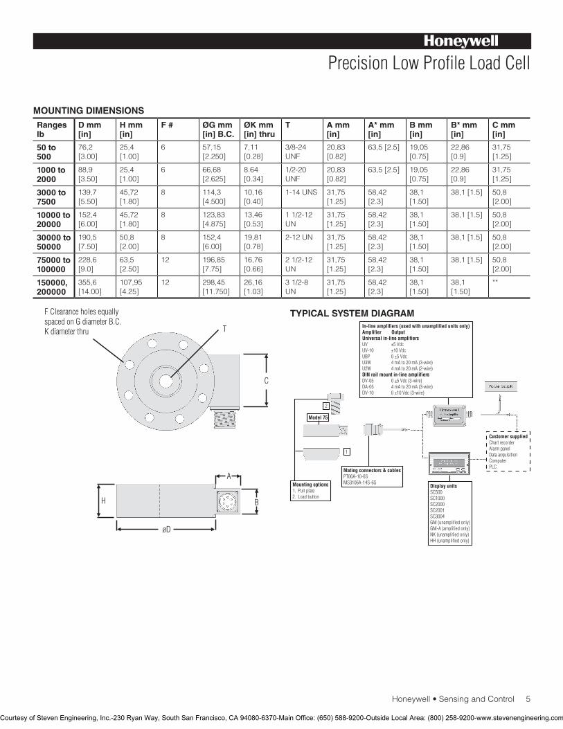
Honeywell•SensingandControl5
Precision Low Profile Load Cell
MOUNTING DIMENSIONS
Ranges lb
D mm [in]
H mm [in]
F # ØG mm [in] B.C.
ØK mm [in] thru
T A mm [in]
A* mm [in]
B mm [in]
B* mm [in]
C mm [in]
50 to 500
76,2[3.00]
25,4[1.00]
6 57,15 [2.250]
7,11 [0.28]
3/8-24UNF
20,83 [0.82]
63,5[2.5] 19,05 [0.75]
22,86[0.9]
31,75 [1.25]
1000 to 2000
88,9 [3.50]
25,4[1.00]
6 66,68[2.625]
8.64[0.34]
1/2-20 UNF
20,83 [0.82]
63,5[2.5] 19,05 [0.75]
22,86[0.9]
31,75 [1.25]
3000 to 7500
139,7 [5.50]
45,72[1.80]
8 114,3[4.500]
10,16[0.40]
1-14UNS 31,75 [1.25]
58,42[2.3]
38,1 [1.50]
38,1[1.5] 50,8 [2.00]
10000 to 20000
152,4[6.00]
45,72[1.80]
8 123,83 [4.875]
13,46[0.53]
1 1/2-12 UN
31,75 [1.25]
58,42[2.3]
38,1 [1.50]
38,1[1.5] 50,8 [2.00]
30000 to 50000
190,5 [7.50]
50,8 [2.00]
8 152,4[6.00]
19,81 [0.78]
2-12UN 31,75 [1.25]
58,42[2.3]
38,1 [1.50]
38,1[1.5] 50,8 [2.00]
75000 to 100000
228,6[9.0]
63,5[2.50]
12 196,85[7.75]
16,76[0.66]
2 1/2-12 UN
31,75 [1.25]
58,42[2.3]
38,1 [1.50]
38,1[1.5] 50,8 [2.00]
150000, 200000
355,6[14.00]
107,95 [4.25]
12 298,45[11.750]
26,16[1.03]
3 1/2-8 UN
31,75 [1.25]
58,42[2.3]
38,1 [1.50]
38,1 [1.50]
**
TYPICAL SYSTEM DIAGRAM
Courtesy of Steven Engineering, Inc.-230 Ryan Way, South San Francisco, CA 94080-6370-Main Office: (650) 588-9200-Outside Local Area: (800) 258-9200-www.stevenengineering.com
SensingandControl
AutomationandControlSolutions
Honeywell
1985DouglasDriveNorth
GoldenValley,MN55422USA
+1-815-235-6847
www.honeywell.com/sensing
008611-1-EN IL50 GLO May 2008Copyright © 2008 Honeywell International Inc. All rights reserved.
Model 75 Precision Low Profile Load Cell
Warranty. Honeywell warrants goods of its manufacture as being free of defective materials and faulty workmanship. Honeywell’s standard product warranty applies unless agreed tootherwisebyHoneywellinwriting;pleaserefertoyourorder acknowledgement or consult your local sales office for specificwarrantydetails.IfwarrantedgoodsarereturnedtoHoneywell during the period of coverage, Honeywell will repair or replace, at its option, without charge those items it finds defective. The foregoing is buyer’s sole remedy and is in lieu of all warranties, expressed or implied, including those of merchantability and fitness for a particular purpose. In no event shall Honeywell be liable for consequential, special, or indirect damages.
While we provide application assistance personally, through our literature and the Honeywell web site, it is up to the customer to determine the suitability of the product in the application.
Specificationsmaychangewithoutnotice.Theinformationwesupply is believed to be accurate and reliable as of this printing. However, we assume no responsibility for its use.
FormoreinformationaboutSensingandControlproducts,visitwww.honeywell.com/sensingorcall+1-815-235-6847Emailinquiriestoinfo.sc@honeywell.com
WARNINGPERSONAL INJURY•DONOTUSEtheseproductsassafetyoremergencystopdevicesorinanyotherapplicationwherefailureoftheproductcouldresultinpersonalinjury.
Failure to comply with these instructions could result in death or serious injury.
WARNINGMISUSE OF DOCUMENTATION•Theinformationpresentedinthiscatalogueisforreferenceonly.DONOTUSEthisdocumentasproductinstallationinformation.•Completeinstallation,operationandmaintenanceinformationisprovidedintheinstructionssuppliedwitheachproduct.
Failure to comply with these instructions could result in death or serious injury.
NOTES
1. Cdimensionvariesonhighranges.Consultfactory.2. Allowablemaximumloads-maximumloadtobeappliedwithout
damage.3 3. Without damage - loading to this level will not cause excessive zero
shift or performance degradation. The user must consider fatigue life forlongtermuseandstructuralintegrity.Allstructurallycriticalap-plications (overhead loading, etc.) should always be designed with safety redundant load paths.
4. Interconnectingshuntcal.1terminalwithshuntcal.2terminalprovides50%(unamplifiedunits),75%(4mAto20mAthree-wireunits)or80%(voltageamplifiedunits)offullscaleoutputforquickcalibration.Shuntcalibrationcomesstandardwithinternalamplifieroption 2a, 2b, 2c, 2t and 2j.
5. O=Orange;Y=Yellow;B=Blue;Bl=Black; R=Red;Br=Brown;W=White;G=Green.Colorspecifyingcableandnumberorletter
specifying connector. 6. Nomatingconnectornecessaryforcableoption.7.ConsultfactoryforTEDSavailabilitywithamplifiedmodels.8. Rangedependent;consultfactory.Terminationdependent;consult
factory.9. Internalampandterminationdependent;consultfactory.10.ThisunitcalibratedtoImperial(non-Metric)units.11.Input/outputisolationonlyavailablewithvoltageoutput(2bor2c)
amplifiers.12.5000ohmbridgerequired.13.Cannotbeusedwithamplifiedoption.14.Cannotbeusedwithoptions1c,1e,1f,1g,1h,or1i.
Courtesy of Steven Engineering, Inc.-230 Ryan Way, South San Francisco, CA 94080-6370-Main Office: (650) 588-9200-Outside Local Area: (800) 258-9200-www.stevenengineering.com
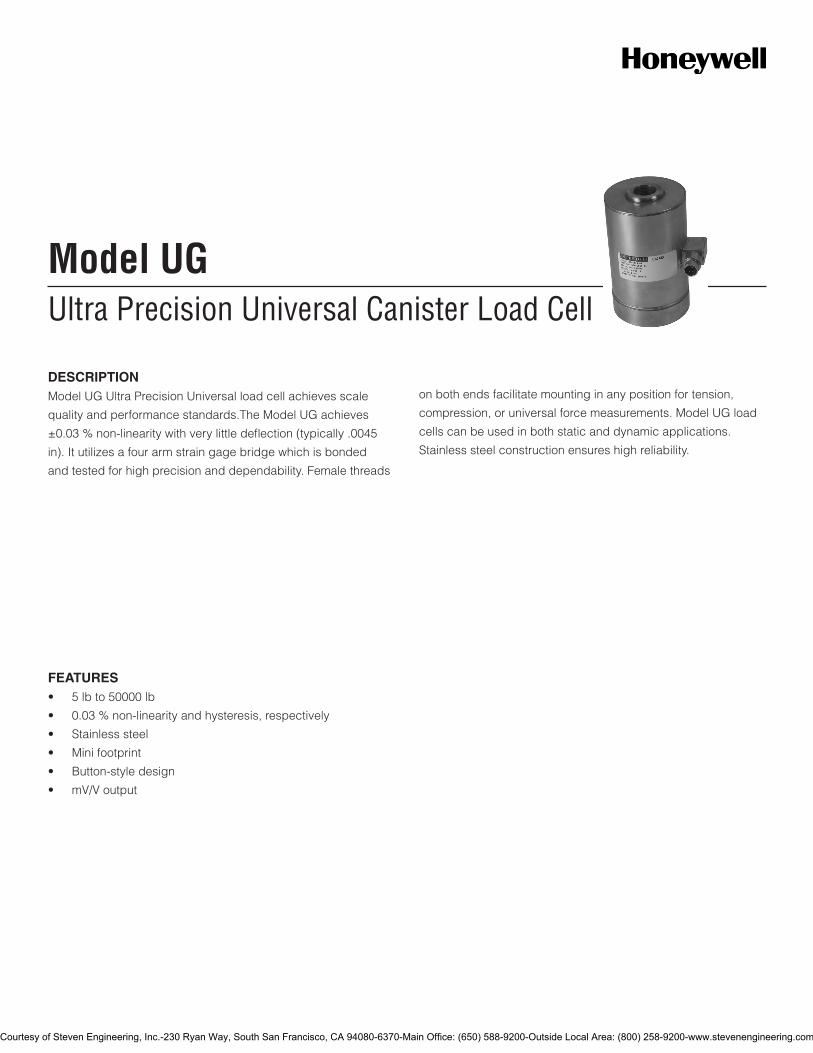
Ultra Precision Universal Canister Load CellModel UG
DESCRIPTIONModel UG Ultra Precision Universal load cell achieves scale
quality and performance standards.The Model UG achieves
±0.03 % non-linearity with very little deflection (typically .0045
in). It utilizes a four arm strain gage bridge which is bonded
and tested for high precision and dependability. Female threads
on both ends facilitate mounting in any position for tension,
compression, or universal force measurements. Model UG load
cells can be used in both static and dynamic applications.
Stainless steel construction ensures high reliability.
FEATURES• 5lbto50000lb
• 0.03%non-linearityandhysteresis,respectively
• Stainlesssteel
• Minifootprint
• Button-styledesign
• mV/Voutput
Courtesy of Steven Engineering, Inc.-230 Ryan Way, South San Francisco, CA 94080-6370-Main Office: (650) 588-9200-Outside Local Area: (800) 258-9200-www.stevenengineering.com
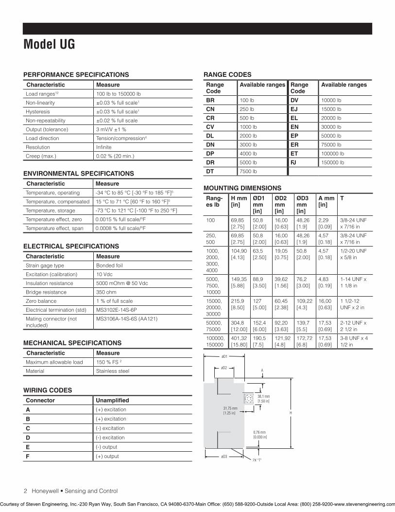
2Honeywell•SensingandControl
Model UG
PERFORMANCE SPECIFICATIONS
Characteristic Measure
Load ranges12 100 lb to 150000 lb
Non-linearity ±0.03 % full scale1
Hysteresis ±0.03 % full scale1
Non-repeatability ±0.02 % full scale
Output (tolerance) 3mV/V±1%
Load direction Tension/compression4
Resolution Infinite
Creep(max.) 0.02 % (20 min.)
ELECTRICAL SPECIFICATIONS
Characteristic Measure
Strain gage type Bondedfoil
Excitation(calibration) 10Vdc
Insulation resistance 5000mOhm@50Vdc
Bridgeresistance 350 ohm
Zero balance 1 % of full scale
Electrical termination (std) MS3102E-14S-6P
Mating connector (not included)
MS3106A-14S-6S (AA121)
MECHANICAL SPECIFICATIONS
Characteristic Measure
Maximumallowableload 150 % FS 2
Material Stainless steel
WIRING CODES
Connector Unamplified
A (+)excitation
B (+)excitation
C (-)excitation
D (-)excitation
E (-) output
F (+) output
ENVIRONMENTAL SPECIFICATIONS
Characteristic Measure
Temperature, operating -34°Cto85°C[-30°Fto185°F]5
Temperature, compensated 15°Cto71°C[60°Fto160°F]5
Temperature, storage -73°Cto121°C[-100°Fto250°F]
Temperature effect, zero 0.0015%fullscale/°F
Temperature effect, span 0.0008%fullscale/°F
MOUNTING DIMENSIONS
Rang-es lb
H mm [in]
ØD1 mm [in]
ØD2 mm [in]
ØD3 mm [in]
A mm [in]
T
100 69,85[2.75]
50,8[2.00]
16,00 [0.63]
48,26[1.9]
2,29 [0.09]
3/8-24UNFx7/16in
250, 500
69,85[2.75]
50,8[2.00]
16,00 [0.63]
48,26[1.9]
4,57[0.18]
3/8-24UNFx7/16in
1000, 2000, 3000, 4000
104,90 [4.13]
63,5 [2.50]
19,05 [0.75]
50,8[2.00]
4,57[0.18]
1/2-20UNFx5/8in
5000, 7500,10000
149,35 [5.88]
88,9[3.50]
39,62 [1.56]
76,2[3.00]
4,83[0.19]
1-14UNFx11/8in
15000, 20000, 30000
215,9 [8.50]
127[5.00]
60,45 [2.38]
109,22 [4.3]
16,00 [0.63]
11/2-12UNFx2in
50000, 75000
304,8[12.00]
152,4 [6.00]
92,20 [3.63]
139,7[5.5]
17,53[0.69]
2-12UNFx21/2in
100000, 150000
401,32 [15.80]
190,5 [7.5]
121,92 [4.8]
172,72[6.8]
17,53[0.69]
3-8UNFx41/2in
RANGE CODES
Range Code
Available ranges Range Code
Available ranges
BR 100 lb DV 10000 lb
CN 250 lb EJ 15000 lb
CR 500 lb EL 20000 lb
CV 1000 lb EN 30000 lb
DL 2000 lb EP 50000 lb
DN 3000 lb ER 75000lb
DP 4000 lb ET 100000 lb
DR 5000 lb FJ 150000 lb
DT 7500lb
Courtesy of Steven Engineering, Inc.-230 Ryan Way, South San Francisco, CA 94080-6370-Main Office: (650) 588-9200-Outside Local Area: (800) 258-9200-www.stevenengineering.com
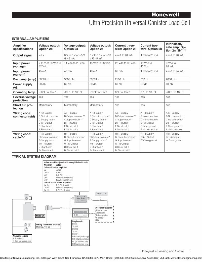
Honeywell•SensingandControl3
Ultra Precision Universal Canister Load Cell
INTERNAL AMPLIFIERS
Amplifier specifications
Voltage output: Option 2b
Voltage output: Option 2c
Voltage output: Option 2t
Current three-wire: Option 2j
Current two-wire: Option 2k
Intrinsically safe amp: Op-tion 2n (2N)***
Output signal ±5V 0Vto5Vor±5V@ 45 mA
0Vto10Vor±10V@45mA
4 mA to 20 mA 4 mA to 20 mA 4 mA to 20 mA
Input power (voltage)
±15Vor26Vdcto32Vdc
11Vdcto28Vdc 15Vdcto28Vdc 22Vdcto32Vdc 15Vdcto 40Vdc
9Vdcto 28Vdc
Input power (current)
45 mA 40 mA 40 mA 65 mA 4mAto28mA 4 mA to 24 mA
Freq. resp (amp) 3000 Hz 3000 Hz 3000 Hz 2500 Hz 300 Hz 2000 Hz
Power supply rej.
60 db 60 db 60 db 60 db 60 db 60 db
Operating temp. -20°Fto185°F -20°Fto185°F -20°Fto185°F 0°Fto185°F 0°Fto185°F -20°Fto185°F
Reverse voltage protection
Yes Yes Yes Yes Yes Yes
Short cir. pro-tection
Momentary Momentary Momentary Yes Yes Yes
Wiring code: connector (std)
A (+) SupplyBOutputcommonCSupplyreturnD (+) OutputE Shunt cal 1F Shunt cal 2
A (+) SupplyBOutputcommon**CSupplyreturn**D (+) OutputE Shunt cal 1F Shunt cal 2
A (+) SupplyBOutputcommon**CSupplyreturn**D (+) OutputE Shunt cal 1F Shunt cal 2
A (+) SupplyBOutputcommon**CSupplyreturn**D (+) OutputE Shunt cal 1F Shunt cal 2
A (+) SupplyBNoconnectionCNoconnectionD (+) OutputECasegroundF No connection
A (+) SupplyBNoconnectionCNoconnectionD (+) OutputECasegroundF No connection
Wiring code: cable5,6,7
R (+) SupplyBlOutputcommonG Supply returnW (+) OutputBShuntcal1BrShuntcal2
R (+) SupplyBlOutputcommon*GSupplyreturn*W (+) OutputBShuntcal1BrShuntcal2
R (+) SupplyBlOutputcommon*GSupplyreturn*W (+) OutputBShuntcal1BrShuntcal2
R (+) SupplyBlOutputcommon*GSupplyreturn*W (+) OutputBShuntcal1BrShuntcal2
R (+) SupplyBl(+)OutputWCaseground
R (+) SupplyBl(+)OutputWCaseground
TYPICAL SYSTEM DIAGRAM
Courtesy of Steven Engineering, Inc.-230 Ryan Way, South San Francisco, CA 94080-6370-Main Office: (650) 588-9200-Outside Local Area: (800) 258-9200-www.stevenengineering.com
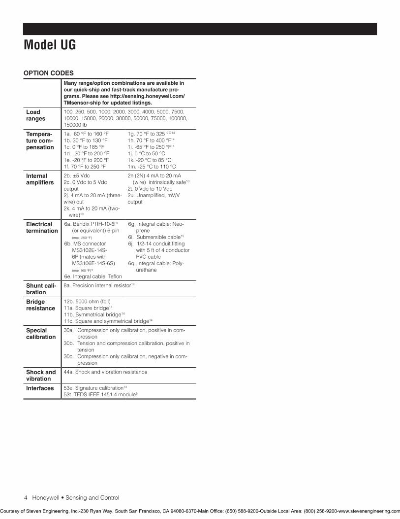
4Honeywell•SensingandControl
Model UG
OPTION CODESMany range/option combinations are available in our quick-ship and fast-track manufacture pro-grams. Please see http://sensing.honeywell.com/TMsensor-ship for updated listings.
Load ranges
100,250,500,1000,2000,3000,4000,5000,7500,10000,15000,20000,30000,50000,75000,100000,150000 lb
Tempera-ture com-pensation
1a. 60 °F to 160 °F1b. 30 °F to 130 °F1c.0°Fto185°F1d. -20 °F to 200 °F1e. -20 °F to 200 °F1f.70°Fto250°F
1g.70°Fto325°F14
1h.70°Fto400°F14
1i. -65 °F to 250 °F14
1j.0°Cto50°C1k.-20°Cto85°C1m.-25°Cto110°C
Internal amplifiers
2b.±5Vdc2c.0Vdcto5Vdcoutput 2j. 4 mA to 20 mA (three-wire) out2k. 4 mA to 20 mA (two-
wire)13
2n (2N) 4 mA to 20 mA (wire) intrinsically safe13
2t.0Vdcto10Vdc2u.Unamplified,mV/Voutput
Electrical termination
6a.BendixPTIH-10-6P(or equivalent) 6-pin (max.250°F)
6b. MS connector MS3102E-14S-6P (mates with MS3106E-14S-6S) (max160°F)16
6e. Integral cable: Teflon
6g. Integral cable: Neo-prene
6i. Submersible cable15
6j.1/2-14conduitfittingwith 5 ft of 4 conductor PVCcable
6q. Integral cable: Poly-urethane
Shunt cali-bration
8a.Precisioninternalresistor14
Bridge resistance
12b. 5000 ohm (foil)11a. Square bridge14
11b. Symmetrical bridge14
11c. Square and symmetrical bridge14
Special calibration
30a. Compressiononlycalibration,positiveincom-pression
30b. Tension and compression calibration, positive in tension
30c. Compressiononlycalibration,negativeincom-pression
Shock and vibration
44a. Shock and vibration resistance
Interfaces 53e. Signature calibration14
53t. TEDS IEEE 1451.4 module9
Courtesy of Steven Engineering, Inc.-230 Ryan Way, South San Francisco, CA 94080-6370-Main Office: (650) 588-9200-Outside Local Area: (800) 258-9200-www.stevenengineering.com
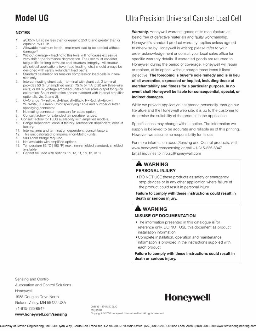
SensingandControl
AutomationandControlSolutions
Honeywell
1985DouglasDriveNorth
GoldenValley,MN55422USA
+1-815-235-6847
www.honeywell.com/sensing
008643-1-EN IL50 GLO May 2008Copyright © 2008 Honeywell International Inc. All rights reserved.
Model UG Ultra Precision Universal Canister Load Cell
NOTES
1. ±0.05% full scale less than or equal to 250 lb and greater than or equalto75000lb.
2. Allowablemaximumloads-maximumloadtobeappliedwithoutdamage.3
3. Withoutdamage–loadingtothislevelwillnotcauseexcessivezero shift or performance degradation. The user must consider fatigue life for long term use and structural integrity. All structur-ally critical applications (overhead loading, etc.) should always be designed with safety redundant load paths.
4. Standardcalibrationfortension/compressionloadcellsisinten-sion only.
5. Interconnecting shunt cal. 1 terminal with shunt cal. 2 terminal provides50%(unamplifiedunits),75%(4mAto20mAthree-wireunits)or80%(voltageamplifiedunits)offullscaleoutputforquickcalibration. Shunt calibration comes standard with internal amplifier option 2b, 2c, 2t and 2j.
6. O=Orange;Y=Yellow;B=Blue;Bl=Black;R=Red;Br=Brown;W=White;G=Green.Colorspecifyingcableandnumberorletterspecifying connector.
7. Nomatingconnectornecessaryforcableoption.8. Consultfactoryforextendedtemperatureranges.9.ConsultfactoryforTEDSavailabilitywithamplifiedmodels.10. Range dependent; consult factory. Termination dependent; consult
factory.11. Internal amp and termination dependent; consult factory.12. This unit calibrated to Imperial (non-Metric) units.13. 5000 ohm bridge required14. Not available with amplified options.15. Temperature82°C[180°F]max.,non-shieldedstandard,shielded
available.16. Cannotbeusedwithoptions1c,1e,1f,1g,1h,or1i.
Warranty. Honeywell warrants goods of its manufacture as being free of defective materials and faulty workmanship. Honeywell’s standard product warranty applies unless agreed to otherwise by Honeywell in writing; please refer to your order acknowledgement or consult your local sales office for specific warranty details. If warranted goods are returned to Honeywell during the period of coverage, Honeywell will repair or replace, at its option, without charge those items it finds defective. The foregoing is buyer’s sole remedy and is in lieu of all warranties, expressed or implied, including those of merchantability and fitness for a particular purpose. In no event shall Honeywell be liable for consequential, special, or indirect damages.
While we provide application assistance personally, through our literature and the Honeywell web site, it is up to the customer to determine the suitability of the product in the application.
Specifications may change without notice. The information we supply is believed to be accurate and reliable as of this printing. However, we assume no responsibility for its use.
FormoreinformationaboutSensingandControlproducts,visitwww.honeywell.com/sensingorcall+1-815-235-6847Email inquiries to [email protected]
WARNINGPERSONAL INJURY•DONOTUSEtheseproductsassafetyoremergencystopdevicesorinanyotherapplicationwherefailureoftheproductcouldresultinpersonalinjury.
Failure to comply with these instructions could result in death or serious injury.
WARNINGMISUSE OF DOCUMENTATION•Theinformationpresentedinthiscatalogueisforreferenceonly.DONOTUSEthisdocumentasproductinstallationinformation.•Completeinstallation,operationandmaintenanceinformationisprovidedintheinstructionssuppliedwitheachproduct.
Failure to comply with these instructions could result in death or serious injury.
Courtesy of Steven Engineering, Inc.-230 Ryan Way, South San Francisco, CA 94080-6370-Main Office: (650) 588-9200-Outside Local Area: (800) 258-9200-www.stevenengineering.com
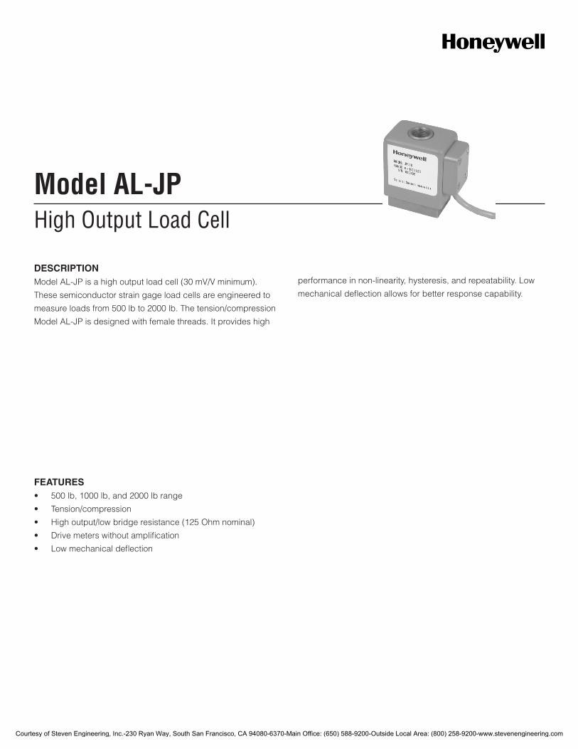
High Output Load CellModel AL-JP
DESCRIPTIONModel AL-JP is a high output load cell (30 mV/V minimum).
These semiconductor strain gage load cells are engineered to
measure loads from 500 lb to 2000 lb. The tension/compression
Model AL-JP is designed with female threads. It provides high
performance in non-linearity, hysteresis, and repeatability. Low
mechanical deflection allows for better response capability.
FEATURES• 500lb,1000lb,and2000lbrange
• Tension/compression
• Highoutput/lowbridgeresistance(125Ohmnominal)
• Drivemeterswithoutamplification
• Lowmechanicaldeflection
Courtesy of Steven Engineering, Inc.-230 Ryan Way, South San Francisco, CA 94080-6370-Main Office: (650) 588-9200-Outside Local Area: (800) 258-9200-www.stevenengineering.com
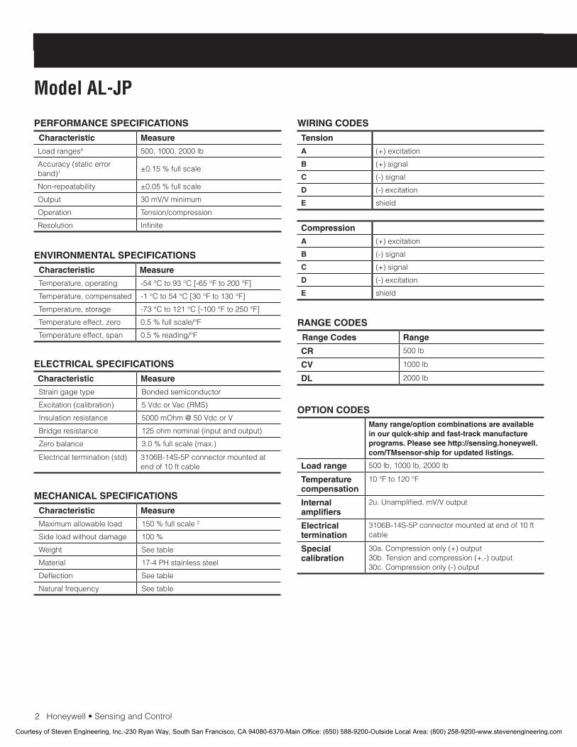
2Honeywell•SensingandControl
Model AL-JP
PERFORMANCE SPECIFICATIONS
Characteristic Measure
Load ranges4 500,1000,2000lb
Accuracy (static error band)1
±0.15%fullscale
Non-repeatability ±0.05%fullscale
Output 30 mV/V minimum
Operation Tension/compression
Resolution Infinite
RANGE CODES
Range Codes Range
CR 500 lb
CV 1000lb
DL 2000 lb
ELECTRICAL SPECIFICATIONS
Characteristic Measure
Straingagetype Bonded semiconductor
Excitation (calibration) 5VdcorVac(RMS)
Insulation resistance 5000mOhm@50VdcorV
Bridge resistance 125ohmnominal(inputandoutput)
Zero balance 3.0%fullscale(max.)
Electrical termination (std) 3106B-14S-5Pconnectormountedatendof10ftcable
MECHANICAL SPECIFICATIONS
Characteristic Measure
Maximum allowable load 150%fullscale2
Sideloadwithoutdamage 100%
Weight Seetable
Material 17-4PHstainlesssteel
Deflection Seetable
Natural frequency Seetable
WIRING CODES
Tension
A (+) excitation
B (+) signal
C (-) signal
D (-) excitation
E shield
Compression
A (+) excitation
B (-) signal
C (+) signal
D (-) excitation
E shield
ENVIRONMENTAL SPECIFICATIONS
Characteristic Measure
Temperature, operating -54°Cto93°C[-65°Fto200°F]
Temperature, compensated -1°Cto54°C[30°Fto130°F]
Temperature, storage -73°Cto121°C[-100°Fto250°F]
Temperature effect, zero 0.5%fullscale/°F
Temperature effect, span 0.5%reading/°F
OPTION CODESMany range/option combinations are available in our quick-ship and fast-track manufacture programs. Please see http://sensing.honeywell.com/TMsensor-ship for updated listings.
Load range 500lb,1000lb,2000lb
Temperaturecompensation
10°Fto120°F
Internal amplifiers
2u.Unamplified,mV/Voutput
Electrical termination
3106B-14S-5Pconnectormountedatendof10ftcable
Special calibration
30a.Compressiononly(+)output30b. Tension and compression (+,-) output30c.Compressiononly(-)output
Courtesy of Steven Engineering, Inc.-230 Ryan Way, South San Francisco, CA 94080-6370-Main Office: (650) 588-9200-Outside Local Area: (800) 258-9200-www.stevenengineering.com

Honeywell•SensingandControl3
High Output Load Cell
MOUNTING DIMENSIONS DEFLECTIONS AND RINGING FREQUENCIES
Capacity Axial deflec-tion at full scale mm [in]
Natural fre-quency (Hz)
Weight kg [lb]
500 lb 0,025 mm [0.0010]
5000 0,544[1.2]
1000lb 0,038 mm [0.0015]
6000 0,544[1.2]
2000 lb 0,051mm[0.0020]
6700 0,544[1.2]
Courtesy of Steven Engineering, Inc.-230 Ryan Way, South San Francisco, CA 94080-6370-Main Office: (650) 588-9200-Outside Local Area: (800) 258-9200-www.stevenengineering.com

008673-2-EN IL50 GLO March 2009Copyright © 2009 Honeywell International Inc. All rights reserved.
Model AL-JP High Output Load Cell
Find out more
Honeywellservesitscustomers
through a worldwide network of
salesoffices,representativesand
distributors.Forapplicationas-
sistance,currentspecifications,
pricing or name of the nearest
AuthorizedDistributor,contact
yourlocalsalesoffice.
TolearnmoreaboutHoneywell’s
test and measurement products,
call +1-614-850-5000, visit
www.honeywell.com/sensotec,
or e-mail inquiries to
Sensing and Control
Honeywell
1985 Douglas Drive North
Golden Valley, MN 55422
www.honeywell.com
NOTES
1. Staticerrorbandistherecommendedperformancespecifica-tion.Thestaticerrorbandiscalculatedasthebestfitstraightlinethrough zero, including the effects of non-linearity, hysteresis and non-repeatability.
2. Allowable maximum loads – maximum load to be applied without damage3.
3. Without damage - loading to this level will not cause excessive zero shift of performance degradation. The user must consider fatigue life for long term use and structural integrity. All structurally critical applications (overhead loading, etc.) should always be designed with safety redundant load paths.
4. This unit calibrated to Imperial (non-Metric) units.
Warranty. Honeywellwarrantsgoodsofitsmanufactureasbeing free of defective materials and faulty workmanship. Honeywell’sstandardproductwarrantyappliesunlessagreedtootherwisebyHoneywellinwriting;pleaserefertoyourorderacknowledgementorconsultyourlocalsalesofficeforspecificwarrantydetails.IfwarrantedgoodsarereturnedtoHoneywellduringtheperiodofcoverage,Honeywellwillrepairorreplace,atitsoption,withoutchargethoseitemsitfindsdefective. The foregoing is buyer’s sole remedy and is in lieu of all warranties, expressed or implied, including those of merchantability and fitness for a particular purpose. In no event shall Honeywell be liable for consequential, special, or indirect damages.
While we provide application assistance personally, through our literatureandtheHoneywellwebsite,itisuptothecustomertodetermine the suitability of the product in the application.
Specificationsmaychangewithoutnotice.Theinformationwesupply is believed to be accurate and reliable as of this printing. However,weassumenoresponsibilityforitsuse.
WARNINGPERSONAL INJURY
•DONOTUSEtheseproductsassafetyoremergencystopdevicesorinanyotherapplicationwherefailureoftheproductcouldresultinpersonalinjury.
Failure to comply with these instructions could result in death or serious injury.
WARNINGMISUSE OF DOCUMENTATION
•Theinformationpresentedinthiscatalogueisforreferenceonly.DONOTUSEthisdocumentasproductinstallationinformation.•Completeinstallation,operationandmaintenanceinformationisprovidedintheinstructionssuppliedwitheachproduct.
Failure to comply with these instructions could result in death or serious injury.
Courtesy of Steven Engineering, Inc.-230 Ryan Way, South San Francisco, CA 94080-6370-Main Office: (650) 588-9200-Outside Local Area: (800) 258-9200-www.stevenengineering.com
High Output Load CellModel AL-SC
DESCRIPTIONModel AL-SC is high-output load cell. These semiconductor
strain gage load cells are engineered to measure loads from 500
lb to 2000 lb. The tension/compression Model AL-SC is de-
signed with female threads. It provides high performance in non-
linearity, hysteresis, and repeatability. Low mechanical deflection
allows for better response capability.
FEATURES• 500lb,1000lb,and2000lbrange
• 0.15%accuracy
• Tension/compression
• Highoutput/lowbridgeresistance
• Lowmechanicaldeflection
Courtesy of Steven Engineering, Inc.-230 Ryan Way, South San Francisco, CA 94080-6370-Main Office: (650) 588-9200-Outside Local Area: (800) 258-9200-www.stevenengineering.com
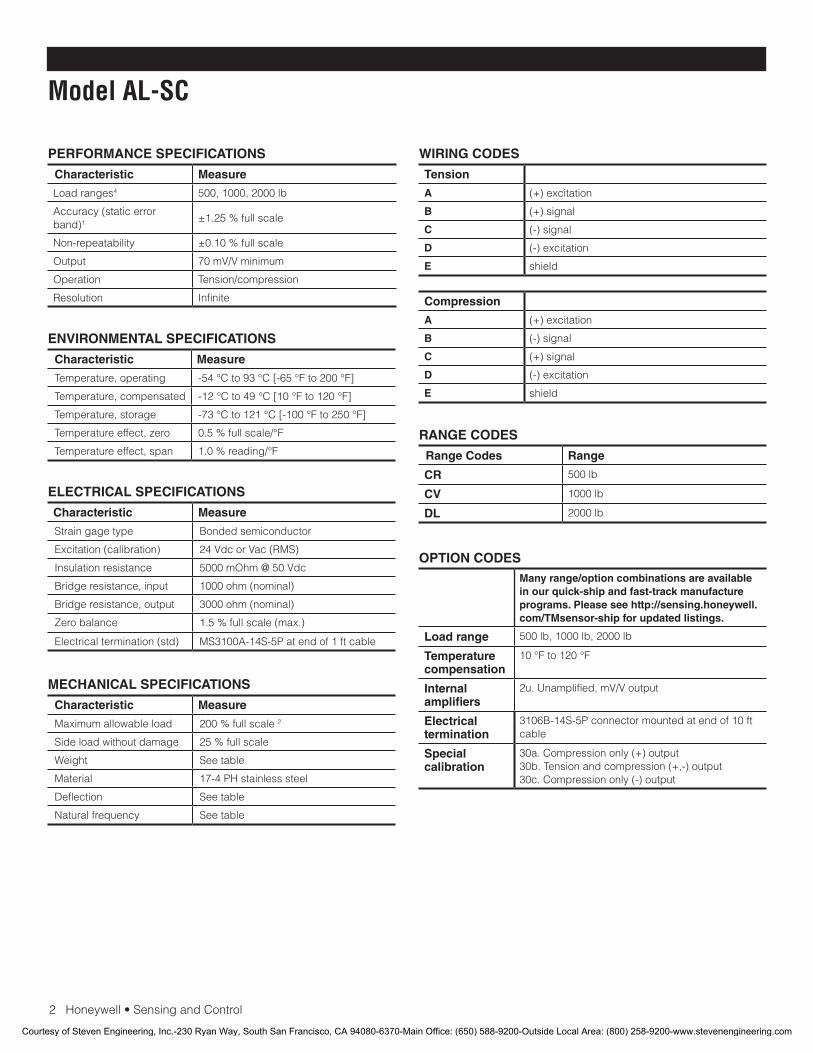
2Honeywell•SensingandControl
Model AL-SC
PERFORMANCE SPECIFICATIONS
Characteristic Measure
Load ranges4 500,1000,2000lb
Accuracy (static error band)1
±1.25%fullscale
Non-repeatability ±0.10%fullscale
Output 70 mV/V minimum
Operation Tension/compression
Resolution Infinite
RANGE CODES
Range Codes Range
CR 500 lb
CV 1000lb
DL 2000 lb
ELECTRICAL SPECIFICATIONS
Characteristic Measure
Strain gage type Bonded semiconductor
Excitation (calibration) 24 Vdc or Vac (RMS)
Insulation resistance 5000 mOhm @ 50 Vdc
Bridge resistance, input 1000ohm(nominal)
Bridge resistance, output 3000 ohm (nominal)
Zero balance 1.5%fullscale(max.)
Electrical termination (std) MS3100A-14S-5Patendof1ftcable
MECHANICAL SPECIFICATIONS
Characteristic Measure
Maximum allowable load 200%fullscale2
Side load without damage 25%fullscale
Weight See table
Material 17-4PHstainlesssteel
Deflection See table
Natural frequency See table
WIRING CODES
Tension
A (+) excitation
B (+) signal
C (-) signal
D (-) excitation
E shield
Compression
A (+) excitation
B (-) signal
C (+) signal
D (-) excitation
E shield
ENVIRONMENTAL SPECIFICATIONS
Characteristic Measure
Temperature, operating -54 °C to 93 °C [-65 °F to 200 °F]
Temperature, compensated -12°Cto49°C[10°Fto120°F]
Temperature, storage -73°Cto121°C[-100°Fto250°F]
Temperature effect, zero 0.5%fullscale/°F
Temperature effect, span 1.0%reading/°F
OPTION CODESMany range/option combinations are available in our quick-ship and fast-track manufacture programs. Please see http://sensing.honeywell.com/TMsensor-ship for updated listings.
Load range 500lb,1000lb,2000lb
Temperaturecompensation
10°Fto120°F
Internal amplifiers
2u. Unamplified, mV/V output
Electrical termination
3106B-14S-5Pconnectormountedatendof10ftcable
Special calibration
30a. Compression only (+) output30b. Tension and compression (+,-) output30c. Compression only (-) output
Courtesy of Steven Engineering, Inc.-230 Ryan Way, South San Francisco, CA 94080-6370-Main Office: (650) 588-9200-Outside Local Area: (800) 258-9200-www.stevenengineering.com
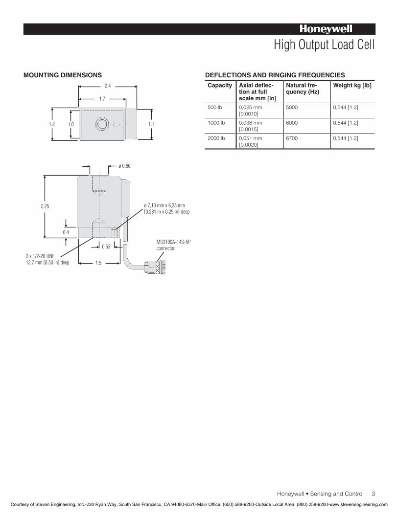
Honeywell•SensingandControl3
High Output Load Cell
MOUNTING DIMENSIONS DEFLECTIONS AND RINGING FREQUENCIES
Capacity Axial deflec-tion at full scale mm [in]
Natural fre-quency (Hz)
Weight kg [lb]
500 lb 0,025 mm [0.0010]
5000 0,544[1.2]
1000lb 0,038 mm [0.0015]
6000 0,544[1.2]
2000 lb 0,051mm[0.0020]
6700 0,544[1.2]
Courtesy of Steven Engineering, Inc.-230 Ryan Way, South San Francisco, CA 94080-6370-Main Office: (650) 588-9200-Outside Local Area: (800) 258-9200-www.stevenengineering.com
Sensing and Control
Automation and Control Solutions
Honeywell
1985DouglasDriveNorth
Golden Valley, MN 55422 USA
+1-815-235-6847
www.honeywell.com/sensing
008672-1-EN IL50 GLO May 2008Copyright © 2008 Honeywell International Inc. All rights reserved.
Model AL-SC High Output Load Cell
NOTES
1. Staticerrorbandistherecommendedperformancespecifica-tion. The static error band is calculated as the best fit straight line through zero, including the effects of linearity, hysteresis and non-repeatability.
2. Allowable maximum loads – maximum load to be applied without damage3.
3. Without damage - loading to this level will not cause excessive zero shift of performance degradation. The user must consider fatigue life for long term use and structural integrity. All structurally critical applications (overhead loading, etc.) should always be designed with safety redundant load paths.
4. This unit calibrated to Imperial (non-Metric) units.
Warranty. Honeywellwarrantsgoodsofitsmanufactureasbeing free of defective materials and faulty workmanship. Honeywell’sstandardproductwarrantyappliesunlessagreedtootherwisebyHoneywellinwriting;pleaserefertoyourorder acknowledgement or consult your local sales office for specific warranty details. If warranted goods are returned to Honeywellduringtheperiodofcoverage,Honeywellwillrepairor replace, at its option, without charge those items it finds defective. The foregoing is buyer’s sole remedy and is in lieu of all warranties, expressed or implied, including those of merchantability and fitness for a particular purpose. In no event shall Honeywell be liable for consequential, special, or indirect damages.
While we provide application assistance personally, through our literatureandtheHoneywellwebsite,itisuptothecustomertodetermine the suitability of the product in the application.
Specifications may change without notice. The information we supply is believed to be accurate and reliable as of this printing. However,weassumenoresponsibilityforitsuse.
For more information about Sensing and Control products, visit www.honeywell.com/sensingorcall+1-815-235-6847Email inquiries to [email protected]
WARNINGPERSONAL INJURY
•DONOTUSEtheseproductsassafetyoremergencystopdevicesorinanyotherapplicationwherefailureoftheproductcouldresultinpersonalinjury.
Failure to comply with these instructions could result in death or serious injury.
WARNINGMISUSE OF DOCUMENTATION
•Theinformationpresentedinthiscatalogueisforreferenceonly.DONOTUSEthisdocumentasproductinstallationinformation.•Completeinstallation,operationandmaintenanceinformationisprovidedintheinstructionssuppliedwitheachproduct.
Failure to comply with these instructions could result in death or serious injury.
Courtesy of Steven Engineering, Inc.-230 Ryan Way, South San Francisco, CA 94080-6370-Main Office: (650) 588-9200-Outside Local Area: (800) 258-9200-www.stevenengineering.com
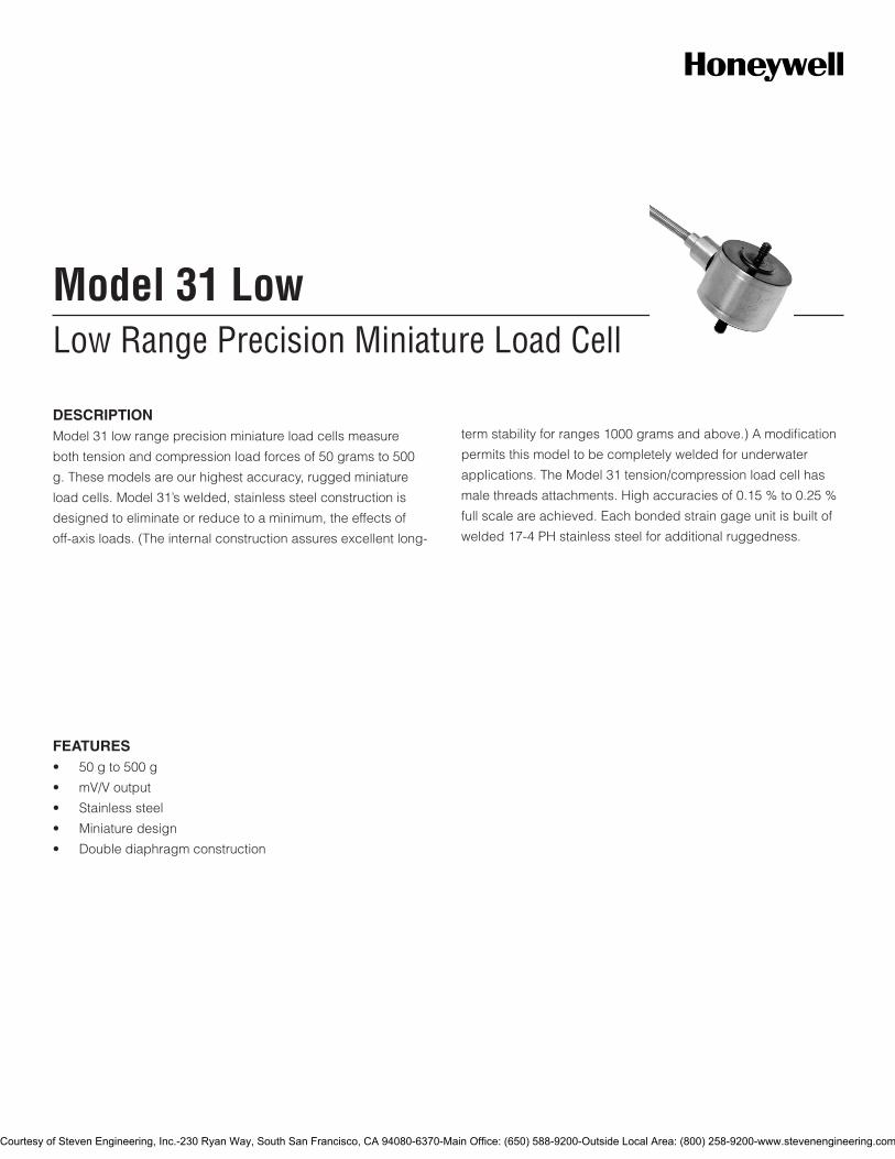
Low Range Precision Miniature Load CellModel 31 Low
DESCRIPTIONModel 31 low range precision miniature load cells measure
both tension and compression load forces of 50 grams to 500
g. These models are our highest accuracy, rugged miniature
load cells. Model 31’s welded, stainless steel construction is
designed to eliminate or reduce to a minimum, the effects of
off-axis loads. (The internal construction assures excellent long-
term stability for ranges 1000 grams and above.) A modification
permits this model to be completely welded for underwater
applications. The Model 31 tension/compression load cell has
male threads attachments. High accuracies of 0.15 % to 0.25 %
full scale are achieved. Each bonded strain gage unit is built of
welded 17-4 PH stainless steel for additional ruggedness.
FEATURES• 50gto500g
• mV/Voutput
• Stainlesssteel
• Miniaturedesign
• Doublediaphragmconstruction
Courtesy of Steven Engineering, Inc.-230 Ryan Way, South San Francisco, CA 94080-6370-Main Office: (650) 588-9200-Outside Local Area: (800) 258-9200-www.stevenengineering.com
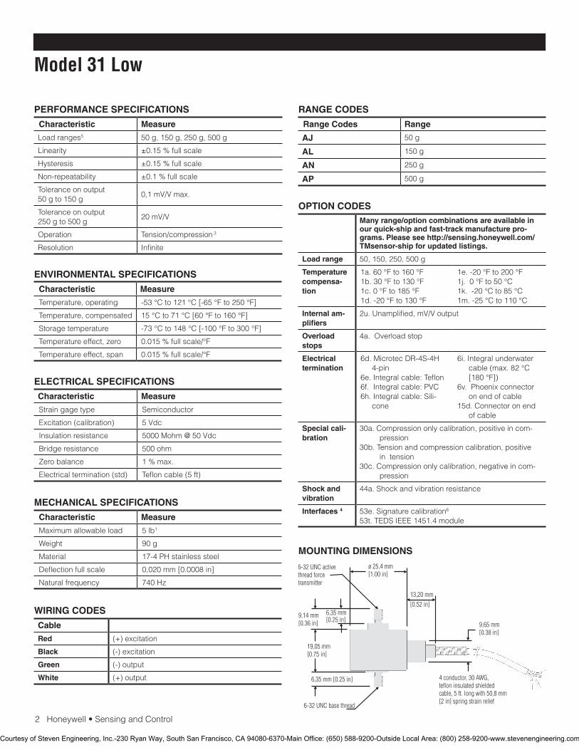
2Honeywell•SensingandControl
Model 31 Low
PERFORMANCE SPECIFICATIONS
Characteristic Measure
Load ranges5 50 g, 150 g, 250 g, 500 g
Linearity ±0.15 % full scale
Hysteresis ±0.15 % full scale
Non-repeatability ±0.1 % full scale
Tolerance on output 50 g to 150 g
0,1mV/Vmax.
Tolerance on output 250 g to 500 g
20mV/V
Operation Tension/compression 3
Resolution Infinite
RANGE CODES
Range Codes Range
AJ 50 g
AL 150 g
AN 250 g
AP 500 g
ELECTRICAL SPECIFICATIONS
Characteristic Measure
Straingagetype Semiconductor
Excitation (calibration) 5Vdc
Insulation resistance 5000Mohm@50Vdc
Bridge resistance 500 ohm
Zero balance 1 % max.
Electrical termination (std) Teflon cable (5 ft)
MECHANICAL SPECIFICATIONS
Characteristic Measure
Maximum allowable load 5 lb1
Weight 90 g
Material 17-4 PH stainless steel
Deflectionfullscale 0,020 mm [0.0008 in]
Natural frequency 740 Hz
WIRING CODES
Cable
Red (+) excitation
Black (-) excitation
Green (-) output
White (+) output
MOUNTING DIMENSIONS
ENVIRONMENTAL SPECIFICATIONS
Characteristic Measure
Temperature, operating -53°Cto121°C[-65°Fto250°F]
Temperature, compensated 15°Cto71°C[60°Fto160°F]
Storagetemperature -73°Cto148°C[-100°Fto300°F]
Temperature effect, zero 0.015%fullscale/°F
Temperature effect, span 0.015%fullscale/°F
6-32 UNC base thread
OPTION CODESMany range/option combinations are available in our quick-ship and fast-track manufacture pro-grams. Please see http://sensing.honeywell.com/TMsensor-ship for updated listings.
Load range 50, 150, 250, 500 g
Temperature compensa-tion
1a.60°Fto160°F1b.30°Fto130°F1c.0°Fto185°F1d.-20°Fto130°F
1e.-20°Fto200°F1j.0°Fto50°C1k.-20°Cto85°C1m.-25°Cto110°C
Internal am-plifiers
2u.Unamplified,mV/Voutput
Overload stops
4a. Overload stop
Electrical termination
6d.MicrotecDR-4S-4H4-pin
6e.Integralcable:Teflon6f.Integralcable:PVC6h.Integralcable:Sili-
cone
6i.Integralunderwatercable(max.82°C[180°F])
6v.Phoenixconnectoron end of cable
15d.Connectoronendof cable
Special cali-bration
30a.Compressiononlycalibration,positiveincom-pression
30b. Tension and compression calibration, positive in tension
30c.Compressiononlycalibration,negativeincom-pression
Shock and vibration
44a.Shockandvibrationresistance
Interfaces 4 53e.Signaturecalibration6
53t.TEDSIEEE1451.4module
Courtesy of Steven Engineering, Inc.-230 Ryan Way, South San Francisco, CA 94080-6370-Main Office: (650) 588-9200-Outside Local Area: (800) 258-9200-www.stevenengineering.com

SensingandControl
AutomationandControlSolutions
Honeywell
1985DouglasDriveNorth
GoldenValley,MN55422USA
+1-815-235-6847
www.honeywell.com/sensing
008629-1-EN IL50 GLO May 2008Copyright © 2008 Honeywell International Inc. All rights reserved.
Model 31 Low Low Range Precision Miniature Load Cell
TYPICAL SYSTEM DIAGRAM
NOTES
1. Allowable maximum loads - maximum load to be applied without damage. 2
2. Without damage - loading to this level will not cause excessive zero shift or performance degradation. The user must consider fatigue life or long term use and structural integrity. All structurally critical applications (overhead loading, etc.) should always be designed with safety redundant load paths.
3. Standardcalibrationfortension/compressionloadcellsisintensiononly.
4. TEDSavailablewithintegralcableunitsonly.5. This unit calibrated to Imperial (non-Metric) units.6. Signaturecalibrationonlyavailableasinlinemodule.
Warranty. Honeywell warrants goods of its manufacture as being free of defective materials and faulty workmanship. Honeywell’s standard product warranty applies unless agreed to otherwise by Honeywell in writing; please refer to your order acknowledgement or consult your local sales office for specific warranty details. If warranted goods are returned to Honeywell during the period of coverage, Honeywell will repair or replace, at its option, without charge those items it finds defective. The foregoing is buyer’s sole remedy and is in lieu of all warranties, expressed or implied, including those of merchantability and fitness for a particular purpose. In no event shall Honeywell be liable for consequential, special, or indirect damages.
While we provide application assistance personally, through our literature and the Honeywell web site, it is up to the customer to determine the suitability of the product in the application.
Specificationsmaychangewithoutnotice.Theinformationwesupply is believed to be accurate and reliable as of this printing. However, we assume no responsibility for its use.
FormoreinformationaboutSensingandControlproducts,visitwww.honeywell.com/sensingorcall+1-815-235-6847Email inquiries to [email protected]
WARNINGPERSONAL INJURY•DONOTUSEtheseproductsassafetyoremergencystopdevicesorinanyotherapplicationwherefailureoftheproductcouldresultinpersonalinjury.
Failure to comply with these instructions could result in death or serious injury.
WARNINGMISUSE OF DOCUMENTATION•Theinformationpresentedinthiscatalogueisforreferenceonly.DONOTUSEthisdocumentasproductinstallationinformation.•Completeinstallation,operationandmaintenanceinformationisprovidedintheinstructionssuppliedwitheachproduct.
Failure to comply with these instructions could result in death or serious injury.
Courtesy of Steven Engineering, Inc.-230 Ryan Way, South San Francisco, CA 94080-6370-Main Office: (650) 588-9200-Outside Local Area: (800) 258-9200-www.stevenengineering.com
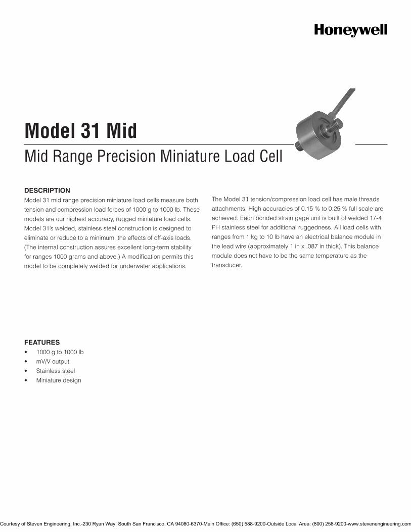
Mid Range Precision Miniature Load CellModel 31 Mid
FEATURES• 1000gto1000lb
• mV/Voutput
• Stainlesssteel
• Miniaturedesign
DESCRIPTIONModel31midrangeprecisionminiatureloadcellsmeasureboth
tensionandcompressionloadforcesof1000gto1000lb.These
modelsareourhighestaccuracy,ruggedminiatureloadcells.
Model31’swelded,stainlesssteelconstructionisdesignedto
eliminateorreducetoaminimum,theeffectsofoff-axisloads.
(Theinternalconstructionassuresexcellentlong-termstability
forranges1000gramsandabove.)Amodificationpermitsthis
modeltobecompletelyweldedforunderwaterapplications.
TheModel31tension/compressionloadcellhasmalethreads
attachments.Highaccuraciesof0.15%to0.25%fullscaleare
achieved.Eachbondedstraingageunitisbuiltofwelded17-4
PHstainlesssteelforadditionalruggedness.Allloadcellswith
rangesfrom1kgto10lbhaveanelectricalbalancemodulein
theleadwire(approximately1inx.087inthick).Thisbalance
moduledoesnothavetobethesametemperatureasthe
transducer.
Courtesy of Steven Engineering, Inc.-230 Ryan Way, South San Francisco, CA 94080-6370-Main Office: (650) 588-9200-Outside Local Area: (800) 258-9200-www.stevenengineering.com
2Honeywell•SensingandControl
Model 31 Mid
PERFORMANCE SPECIFICATIONS
Characteristic Measure
Loadranges6 1000g,5lb,10lb,25lb,50lb,100lb,250lb,500lb,1000lb
Linearity1000gto250lb ±0.15%fullscale
Linearity500lbto1000lb ±0.2%fullscale
Hysteresis1000gto250lb ±0.15%fullscale
Hysteresis500lbto1000lb ±0.2%fullscale
Non-repeatability1000g ±0.1%fullscale
Non-repeatability5lbto1000lb
±0.05%fullscale
Toleranceonoutput1000g 1.5mV/V(nominal)
Toleranceonoutput5lbto1000lb
2mV/V
Operation Tension/compression3
Resolution Infinite
RANGE CODES
Range codes Range
AR 1000g
AT 5lb
AV 10lb
BL 25lb
BN 50lb
BR 100lb
CN 250lb
CR 500lb
CV 1000lb
ELECTRICAL SPECIFICATIONS
Characteristic Measure
Straingagetype Bondedfoil
Excitation(calibration)1kgto10lb
5Vdc
Excitation(calibration)25lbto1000lb
10Vdc
Insulationresistance 5000Mohm@50Vdc
Bridgeresistance 350ohm
Zerobalance 1%max.
Electricaltermination(std) Tefloncable(1524mm[60in])
MECHANICAL SPECIFICATIONS
Characteristic Measure
Maximumallowableload 150%FS1
Weight Seetable
Material 17-4PHstainlesssteel
Deflectionfullscale Seetable
Naturalfrequency Seetable
WIRING CODES
Cable Unamplified
Red (+)excitation
Black (-)excitation
Green (-)output
White (+)output
ENVIRONMENTAL SPECIFICATIONS
Characteristic Measure
Temperature,operating -53°Cto121°C[-65°Fto250°F]
Temperature,compensated 15°Cto71°C[60°Fto160°F]
Storagetemperature -73°Cto148°C[-100°Fto300°F]
Temperatureeffect,zero 0.005%fullscale/°F
Temperatureeffect,span 0.005%fullscale/°F
DEFLECTIONS AND RINGING FREQUENCIES
Capacity (lb)
Deflection at full scale (in)
Ringing fre-quency (Hz)
Weight (g)
1000gto10lb
0,03mm[0.001in] 3000Hz 21g
25lbto100lb
0,03mm[0.001in] 10000Hz 63g
250lbto1000lb
0,04mm[0.0015in] 12000Hz 80g
Courtesy of Steven Engineering, Inc.-230 Ryan Way, South San Francisco, CA 94080-6370-Main Office: (650) 588-9200-Outside Local Area: (800) 258-9200-www.stevenengineering.com
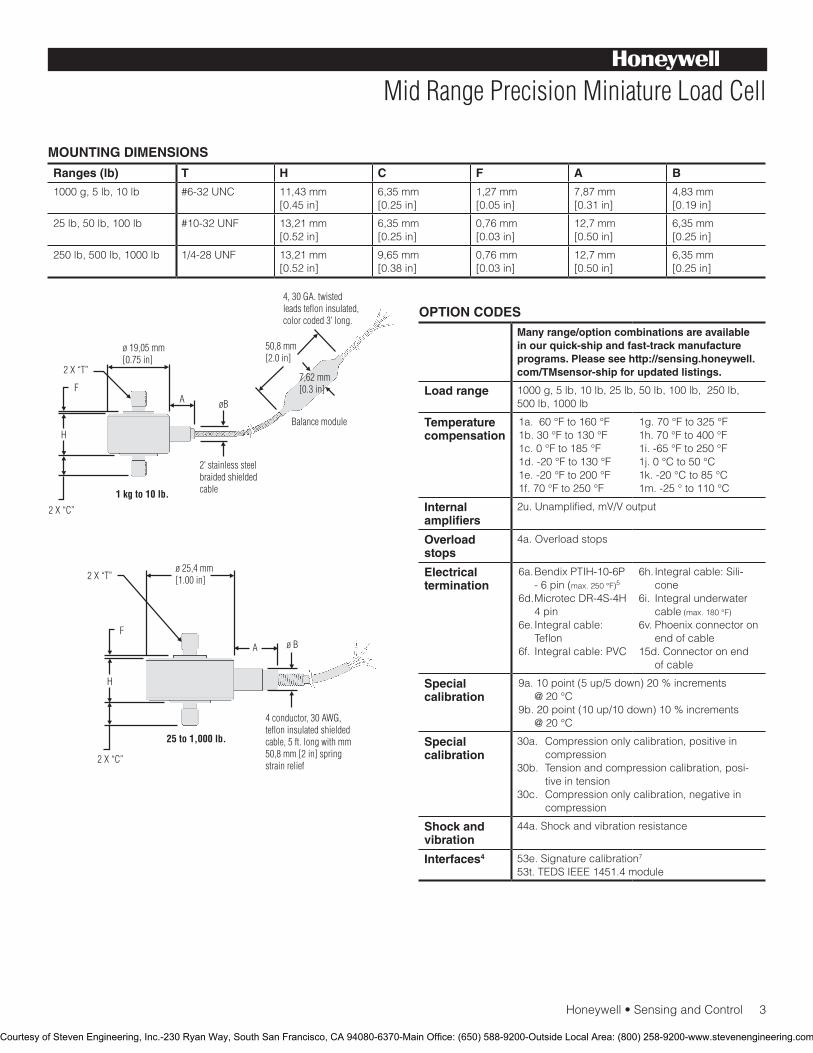
Honeywell•SensingandControl3
Mid Range Precision Miniature Load Cell
MOUNTING DIMENSIONS
Ranges (lb) T H C F A B
1000g,5lb,10lb #6-32UNC 11,43mm[0.45in]
6,35mm[0.25in]
1,27mm[0.05in]
7,87mm[0.31in]
4,83mm[0.19in]
25lb,50lb,100lb #10-32UNF 13,21mm[0.52in]
6,35mm[0.25in]
0,76mm[0.03in]
12,7mm[0.50in]
6,35mm[0.25in]
250lb,500lb,1000lb 1/4-28UNF 13,21mm[0.52in]
9,65mm[0.38in]
0,76mm[0.03in]
12,7mm[0.50in]
6,35mm[0.25in]
OPTION CODESMany range/option combinations are available in our quick-ship and fast-track manufacture programs. Please see http://sensing.honeywell.com/TMsensor-ship for updated listings.
Load range 1000g,5lb,10lb,25lb,50lb,100lb,250lb,500lb,1000lb
Temperaturecompensation
1a.60°Fto160°F1b.30°Fto130°F1c.0°Fto185°F1d.-20°Fto130°F1e.-20°Fto200°F1f.70°Fto250°F
1g.70°Fto325°F1h.70°Fto400°F1i.-65°Fto250°F1j.0°Cto50°C1k.-20°Cto85°C1m.-25°to110°C
Internal amplifiers
2u.Unamplified,mV/Voutput
Overload stops
4a.Overloadstops
Electrical termination
6a.BendixPTIH-10-6P-6pin(max.250°F)5
6d.MicrotecDR-4S-4H4pin
6e.Integralcable:Teflon
6f. Integralcable:PVC
6h.Integralcable:Sili-cone
6i. Integralunderwatercable(max.180°F)
6v.Phoenixconnectoronendofcable
15d.Connectoronendofcable
Special calibration
9a.10point(5up/5down)20%increments@20°C
9b.20point(10up/10down)10%increments@20°C
Special calibration
30a. Compressiononlycalibration,positiveincompression
30b. Tensionandcompressioncalibration,posi-tiveintension
30c. Compressiononlycalibration,negativeincompression
Shock and vibration
44a.Shockandvibrationresistance
Interfaces4 53e.Signaturecalibration7
53t.TEDSIEEE1451.4module
Courtesy of Steven Engineering, Inc.-230 Ryan Way, South San Francisco, CA 94080-6370-Main Office: (650) 588-9200-Outside Local Area: (800) 258-9200-www.stevenengineering.com
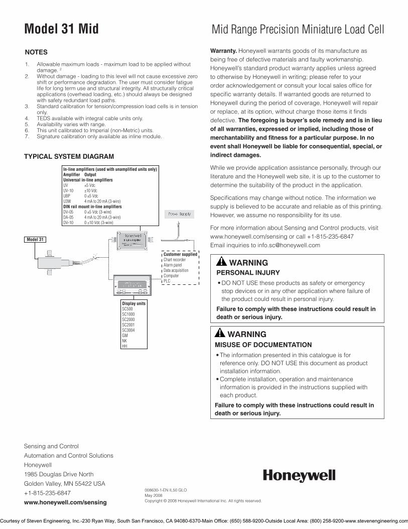
SensingandControl
AutomationandControlSolutions
Honeywell
1985DouglasDriveNorth
GoldenValley,MN55422USA
+1-815-235-6847
www.honeywell.com/sensing
008630-1-EN IL50 GLO May 2008Copyright © 2008 Honeywell International Inc. All rights reserved.
Model 31 Mid Mid Range Precision Miniature Load Cell
TYPICAL SYSTEM DIAGRAM
NOTES
1. Allowablemaximumloads-maximumloadtobeappliedwithout damage.22. Withoutdamage-loadingtothislevelwillnotcauseexcessivezero
shiftorperformancedegradation.Theusermustconsiderfatiguelifeforlongtermuseandstructuralintegrity.Allstructurallycriticalapplications(overheadloading,etc.)shouldalwaysbedesignedwithsafetyredundantloadpaths.
3. Standardcalibrationfortension/compressionloadcellsisintensiononly.
4. TEDSavailablewithintegralcableunitsonly.5. Availabilityvarieswithrange.6. ThisunitcalibratedtoImperial(non-Metric)units.7. Signaturecalibrationonlyavailableasinlinemodule.
Warranty. Honeywellwarrantsgoodsofitsmanufactureasbeingfreeofdefectivematerialsandfaultyworkmanship.Honeywell’sstandardproductwarrantyappliesunlessagreedtootherwisebyHoneywellinwriting;pleaserefertoyourorderacknowledgementorconsultyourlocalsalesofficeforspecificwarrantydetails.IfwarrantedgoodsarereturnedtoHoneywellduringtheperiodofcoverage,Honeywellwillrepairorreplace,atitsoption,withoutchargethoseitemsitfindsdefective.The foregoing is buyer’s sole remedy and is in lieu of all warranties, expressed or implied, including those of merchantability and fitness for a particular purpose. In no event shall Honeywell be liable for consequential, special, or indirect damages.
Whileweprovideapplicationassistancepersonally,throughourliteratureandtheHoneywellwebsite,itisuptothecustomertodeterminethesuitabilityoftheproductintheapplication.
Specificationsmaychangewithoutnotice.Theinformationwesupplyisbelievedtobeaccurateandreliableasofthisprinting.However,weassumenoresponsibilityforitsuse.
FormoreinformationaboutSensingandControlproducts,visitwww.honeywell.com/sensingorcall+1-815-235-6847Emailinquiriestoinfo.sc@honeywell.com
WARNINGPERSONAL INJURY•DONOTUSEtheseproductsassafetyoremergencystopdevicesorinanyotherapplicationwherefailureoftheproductcouldresultinpersonalinjury.
Failure to comply with these instructions could result in death or serious injury.
WARNINGMISUSE OF DOCUMENTATION•Theinformationpresentedinthiscatalogueisforreferenceonly.DONOTUSEthisdocumentasproductinstallationinformation.•Completeinstallation,operationandmaintenanceinformationisprovidedintheinstructionssuppliedwitheachproduct.
Failure to comply with these instructions could result in death or serious injury.
Courtesy of Steven Engineering, Inc.-230 Ryan Way, South San Francisco, CA 94080-6370-Main Office: (650) 588-9200-Outside Local Area: (800) 258-9200-www.stevenengineering.com
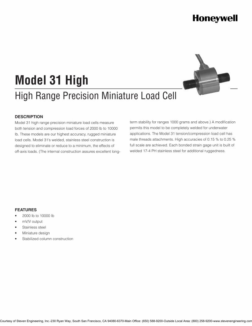
High Range Precision Miniature Load CellModel 31 High
FEATURES• 2000lbto10000lb
• mV/Voutput
• Stainlesssteel
• Miniaturedesign
• Stabilizedcolumnconstruction
DESCRIPTIONModel31highrangeprecisionminiatureloadcellsmeasure
bothtensionandcompressionloadforcesof2000lbto10000
lb.Thesemodelsareourhighestaccuracy,ruggedminiature
loadcells.Model31’swelded,stainlesssteelconstructionis
designedtoeliminateorreducetoaminimum,theeffectsof
off-axisloads.(Theinternalconstructionassuresexcellentlong-
termstabilityforranges1000gramsandabove.)Amodification
permitsthismodeltobecompletelyweldedforunderwater
applications.TheModel31tension/compressionloadcellhas
malethreadsattachments.Highaccuraciesof0.15%to0.25%
fullscaleareachieved.Eachbondedstraingageunitisbuiltof
welded17-4PHstainlesssteelforadditionalruggedness.
Courtesy of Steven Engineering, Inc.-230 Ryan Way, South San Francisco, CA 94080-6370-Main Office: (650) 588-9200-Outside Local Area: (800) 258-9200-www.stevenengineering.com
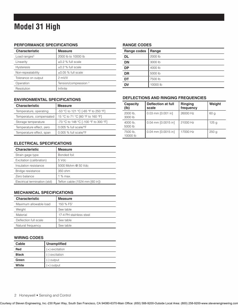
2Honeywell•SensingandControl
Model 31 High
PERFORMANCE SPECIFICATIONS
Characteristic Measure
Loadranges5 2000lbto10000lb
Linearity ±0.2%fullscale
Hysteresis ±0.2%fullscale
Non-repeatability ±0.05%fullscale
Toleranceonoutput 2mV/V
Operation Tension/compression3
Resolution Infinite
RANGE CODES
Range codes Range
DL 2000lb
DN 3000lb
DP 4000lb
DR 5000lb
DT 7500lb
DV 10000lb
ELECTRICAL SPECIFICATIONS
Characteristic Measure
Straingagetype Bondedfoil
Excitation(calibration) 5Vdc
Insulationresistance 5000Mohm@50Vdc
Bridgeresistance 350ohm
Zerobalance 1%max.
Electricaltermination(std) Tefloncable(1524mm[60in])
MECHANICAL SPECIFICATIONS
Characteristic Measure
Maximumallowableload 150%FS1
Weight Seetable
Material 17-4PHstainlesssteel
Deflectionfullscale Seetable
Naturalfrequency Seetable
WIRING CODES
Cable Unamplified
Red (+)excitation
Black (-)excitation
Green (-)output
White (+)output
ENVIRONMENTAL SPECIFICATIONS
Characteristic Measure
Temperature,operating -53°Cto121°C[-65°Fto250°F]
Temperature,compensated 15°Cto71°C[60°Fto160°F]
Storagetemperature -73°Cto148°C[-100°Fto300°F]
Temperatureeffect,zero 0.005%fullscale/°F
Temperatureeffect,span 0.005%fullscale/°F
DEFLECTIONS AND RINGING FREQUENCIES
Capacity (lb)
Deflection at full scale
Ringing frequency
Weight
2000lb,3000lb
0.03mm[0.001in] 26000Hz 60g
4000lb,5000lb
0.04mm[0.0015in] 21000Hz 125g
7500lb,10000lb
0.04mm[0.0015in] 17000Hz 250g
Courtesy of Steven Engineering, Inc.-230 Ryan Way, South San Francisco, CA 94080-6370-Main Office: (650) 588-9200-Outside Local Area: (800) 258-9200-www.stevenengineering.com
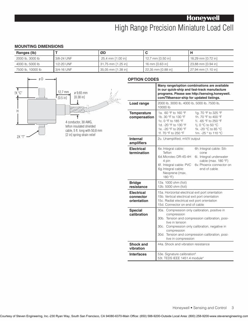
Honeywell•SensingandControl3
High Range Precision Miniature Load Cell
MOUNTING DIMENSIONS
Ranges (lb) T ØD C H
2000lb,3000lb 3/8-24UNF 25,4mm[1.00in] 12,7mm[0.50in] 18,29mm[0.72in]
4000lb,5000lb 1/2-20UNF 31,75mm[1.25in] 16mm[0.63in] 23,88mm[0.94in]
7500lb,10000lb 3/4-16UNF 35,05mm[1.38in] 22,35mm[0.88in] 27,94mm[1.10in]
OPTION CODESMany range/option combinations are available in our quick-ship and fast-track manufacture programs. Please see http://sensing.honeywell.com/TMsensor-ship for updated listings.
Load range 2000lb,3000lb,4000lb,5000lb,7500lb,10000lb
Temperaturecompensation
1a.60°Fto160°F1b.30°Fto130°F1c.0°Fto185°F1d.-20°Fto130°F1e.-20°Fto200°F1f.70°Fto250°F
1g.70°Fto325°F1h.70°Fto400°F1i.-65°Fto250°F1j.0°Cto50°C1k.-20°Cto85°C1m.-25°to110°C
Internal amplifiers
2u.Unamplified,mV/Voutput
Electrical termination
6e.Integralcable:Teflon
6d.MicrotecDR-4S-4H4pin
6f. Integralcable:PVC6g.Integralcable:
Neoprene(max.180°F)
6h.Integralcable:Sili-cone
6i. Integralunderwatercable(max.180°F)
6v.Phoenixconnectoronendofcable
Bridge resistance
12a.1000ohm(foil)12b.5000ohm(foil)
Electrical connector orientation
15a.Horizontalelectricalexitportorientation15b.Verticalelectricalexitportorientation15c.Radialelectricalexitportorientation15d.Connectoronendofcable
Special calibration
30a. Compressiononlycalibration,positiveincompression
30b. Tensionandcompressioncalibration,posi-tiveintension
30c. Compressiononlycalibration,negativeincompression
30d. Tensionandcompressioncalibration,posi-tiveincompression
Shock and vibration
44a.Shockandvibrationresistance
Interfaces 53e.Signaturecalibration6
53t.TEDSIEEE1451.4module4
Courtesy of Steven Engineering, Inc.-230 Ryan Way, South San Francisco, CA 94080-6370-Main Office: (650) 588-9200-Outside Local Area: (800) 258-9200-www.stevenengineering.com
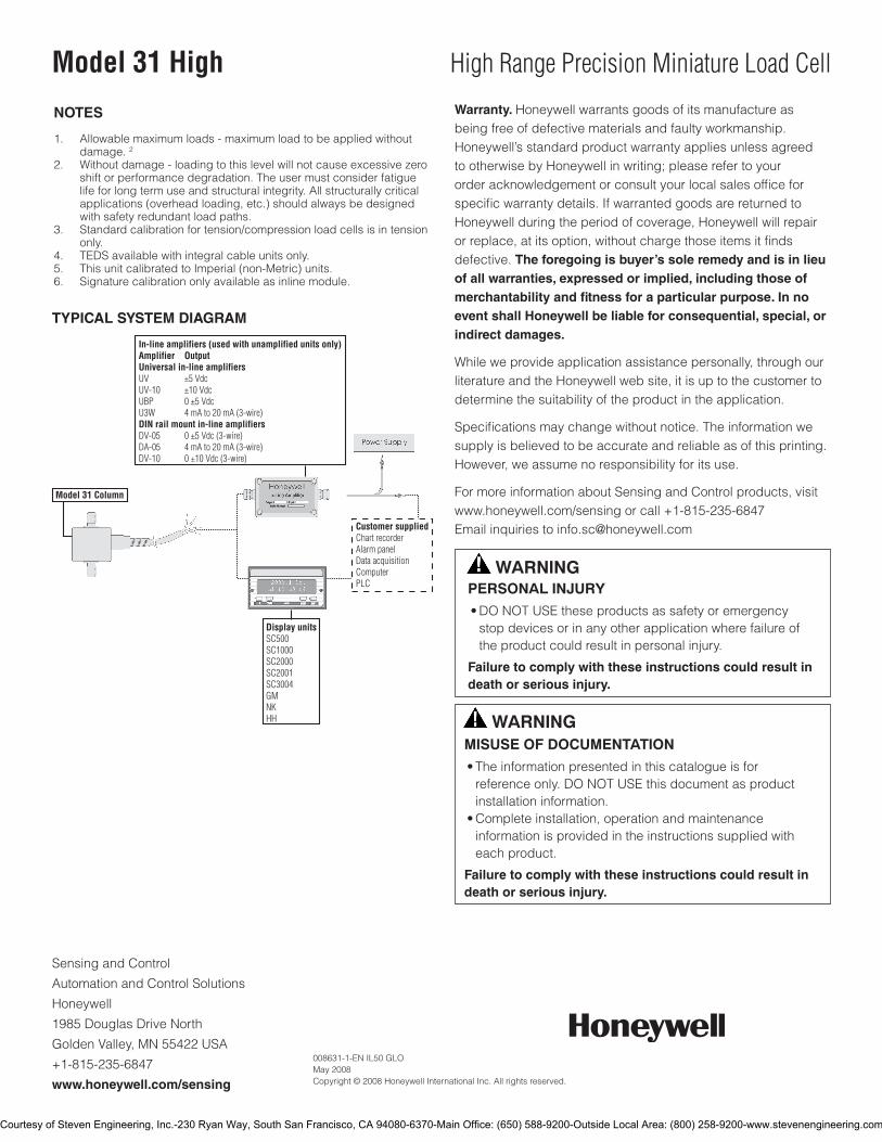
SensingandControl
AutomationandControlSolutions
Honeywell
1985DouglasDriveNorth
GoldenValley,MN55422USA
+1-815-235-6847
www.honeywell.com/sensing
008631-1-EN IL50 GLO May 2008Copyright © 2008 Honeywell International Inc. All rights reserved.
Model 31 High High Range Precision Miniature Load Cell
TYPICAL SYSTEM DIAGRAM
NOTES
1. Allowablemaximumloads-maximumloadtobeappliedwithout damage.22. Withoutdamage-loadingtothislevelwillnotcauseexcessivezero
shiftorperformancedegradation.Theusermustconsiderfatiguelifeforlongtermuseandstructuralintegrity.Allstructurallycriticalapplications(overheadloading,etc.)shouldalwaysbedesignedwithsafetyredundantloadpaths.
3. Standardcalibrationfortension/compressionloadcellsisintensiononly.
4. TEDSavailablewithintegralcableunitsonly.5. ThisunitcalibratedtoImperial(non-Metric)units.6. Signaturecalibrationonlyavailableasinlinemodule.
Warranty. Honeywellwarrantsgoodsofitsmanufactureasbeingfreeofdefectivematerialsandfaultyworkmanship.Honeywell’sstandardproductwarrantyappliesunlessagreedtootherwisebyHoneywellinwriting;pleaserefertoyourorderacknowledgementorconsultyourlocalsalesofficeforspecificwarrantydetails.IfwarrantedgoodsarereturnedtoHoneywellduringtheperiodofcoverage,Honeywellwillrepairorreplace,atitsoption,withoutchargethoseitemsitfindsdefective.The foregoing is buyer’s sole remedy and is in lieu of all warranties, expressed or implied, including those of merchantability and fitness for a particular purpose. In no event shall Honeywell be liable for consequential, special, or indirect damages.
Whileweprovideapplicationassistancepersonally,throughourliteratureandtheHoneywellwebsite,itisuptothecustomertodeterminethesuitabilityoftheproductintheapplication.
Specificationsmaychangewithoutnotice.Theinformationwesupplyisbelievedtobeaccurateandreliableasofthisprinting.However,weassumenoresponsibilityforitsuse.
FormoreinformationaboutSensingandControlproducts,visitwww.honeywell.com/sensingorcall+1-815-235-6847Emailinquiriestoinfo.sc@honeywell.com
WARNINGPERSONAL INJURY•DONOTUSEtheseproductsassafetyoremergencystopdevicesorinanyotherapplicationwherefailureoftheproductcouldresultinpersonalinjury.
Failure to comply with these instructions could result in death or serious injury.
WARNINGMISUSE OF DOCUMENTATION•Theinformationpresentedinthiscatalogueisforreferenceonly.DONOTUSEthisdocumentasproductinstallationinformation.•Completeinstallation,operationandmaintenanceinformationisprovidedintheinstructionssuppliedwitheachproduct.
Failure to comply with these instructions could result in death or serious injury.
Courtesy of Steven Engineering, Inc.-230 Ryan Way, South San Francisco, CA 94080-6370-Main Office: (650) 588-9200-Outside Local Area: (800) 258-9200-www.stevenengineering.com

Precision Miniature Load CellModel 34
FEATURES• 1000gto1000lb
• Weldedstainlesssteel
• Rugged,smallsize
• Tension/compression
• 0.15%/0.20%accuracy
DESCRIPTIONModel34precisionminiatureloadcellsmeasurebothtension
andcompressionloadforcesof1000gto1000lb.These
modelsareourhighestaccuracy,ruggedminiatureloadcells.
Model34’swelded,stainlesssteelconstructionisdesignedto
eliminateorreducetoaminimum,theeffectsofoff-axisloads.
(Theinternalconstructionassuresexcellentlong-termstability
forranges1000gramsandabove.)Amodificationpermitsthis
modeltobecompletelyweldedforunderwaterapplications.
TheModel34tension/compressionloadcellhasfemalethreads
attachments.Highaccuraciesof0.15%to0.25%fullscaleare
achieved.Eachbondedstraingageunitisbuiltofwelded17-4
PHstainlesssteelforadditionalruggedness.Allloadcellswith
rangesfrom1kgto10lbhaveanelectricalbalancemodulein
theleadwire(approximately1inx.087inthick).Thisbalance
moduledoesnothavetobethesametemperatureasthe
transducer.
Courtesy of Steven Engineering, Inc.-230 Ryan Way, South San Francisco, CA 94080-6370-Main Office: (650) 588-9200-Outside Local Area: (800) 258-9200-www.stevenengineering.com
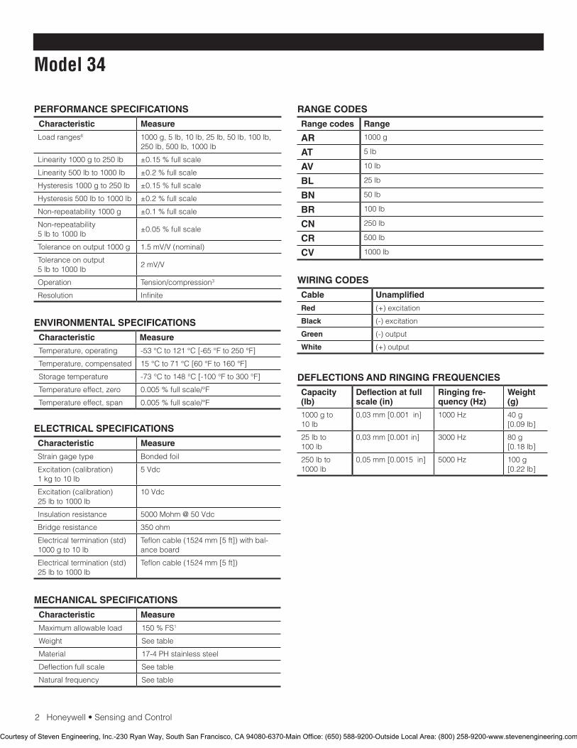
2Honeywell•SensingandControl
Model 34
PERFORMANCE SPECIFICATIONS
Characteristic Measure
Loadranges6 1000g,5lb,10lb,25lb,50lb,100lb,250lb,500lb,1000lb
Linearity1000gto250lb ±0.15%fullscale
Linearity500lbto1000lb ±0.2%fullscale
Hysteresis1000gto250lb ±0.15%fullscale
Hysteresis500lbto1000lb ±0.2%fullscale
Non-repeatability1000g ±0.1%fullscale
Non-repeatability5lbto1000lb
±0.05%fullscale
Toleranceonoutput1000g 1.5mV/V(nominal)
Toleranceonoutput5lbto1000lb
2mV/V
Operation Tension/compression3
Resolution Infinite
RANGE CODES
Range codes Range
AR 1000g
AT 5lb
AV 10lb
BL 25lb
BN 50lb
BR 100lb
CN 250lb
CR 500lb
CV 1000lb
ELECTRICAL SPECIFICATIONS
Characteristic Measure
Straingagetype Bondedfoil
Excitation(calibration)1kgto10lb
5Vdc
Excitation(calibration)25lbto1000lb
10Vdc
Insulationresistance 5000Mohm@50Vdc
Bridgeresistance 350ohm
Electricaltermination(std)1000gto10lb
Tefloncable(1524mm[5ft])withbal-anceboard
Electricaltermination(std)25lbto1000lb
Tefloncable(1524mm[5ft])
MECHANICAL SPECIFICATIONS
Characteristic Measure
Maximumallowableload 150%FS1
Weight Seetable
Material 17-4PHstainlesssteel
Deflectionfullscale Seetable
Naturalfrequency Seetable
WIRING CODES
Cable Unamplified
Red (+)excitation
Black (-)excitation
Green (-)output
White (+)output
ENVIRONMENTAL SPECIFICATIONS
Characteristic Measure
Temperature,operating -53°Cto121°C[-65°Fto250°F]
Temperature,compensated 15°Cto71°C[60°Fto160°F]
Storagetemperature -73°Cto148°C[-100°Fto300°F]
Temperatureeffect,zero 0.005%fullscale/°F
Temperatureeffect,span 0.005%fullscale/°F
DEFLECTIONS AND RINGING FREQUENCIES
Capacity (lb)
Deflection at full scale (in)
Ringing fre-quency (Hz)
Weight (g)
1000gto10lb
0,03mm[0.001in] 1000Hz 40g[0.09lb]
25lbto100lb
0,03mm[0.001in] 3000Hz 80g[0.18lb]
250lbto1000lb
0,05mm[0.0015in] 5000Hz 100g[0.22lb]
Courtesy of Steven Engineering, Inc.-230 Ryan Way, South San Francisco, CA 94080-6370-Main Office: (650) 588-9200-Outside Local Area: (800) 258-9200-www.stevenengineering.com
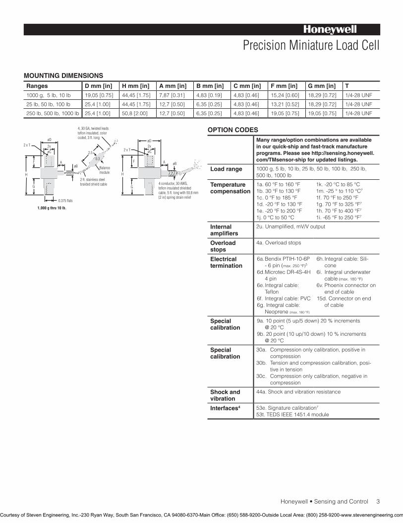
Honeywell•SensingandControl3
Precision Miniature Load Cell
MOUNTING DIMENSIONS
Ranges D mm [in] H mm [in] A mm [in] B mm [in] C mm [in] F mm [in] G mm [in] T
1000g,5lb,10lb 19,05[0.75] 44,45[1.75] 7,87[0.31] 4,83[0.19] 4,83[0.46] 15,24[0.60] 18,29[0.72] 1/4-28UNF
25lb,50lb,100lb 25,4[1.00] 44,45[1.75] 12,7[0.50] 6,35[0.25] 4,83[0.46] 13,21[0.52] 18,29[0.72] 1/4-28UNF
250lb,500lb,1000lb 25,4[1.00] 50,8[2.00] 12,7[0.50] 6,35[0.25] 4,83[0.46] 19,05[0.75] 19,05[0.75] 1/4-28UNF
OPTION CODESMany range/option combinations are available in our quick-ship and fast-track manufacture programs. Please see http://sensing.honeywell.com/TMsensor-ship for updated listings.
Load range 1000g,5lb,10lb,25lb,50lb,100lb,250lb,500lb,1000lb
Temperaturecompensation
1a.60°Fto160°F1b.30°Fto130°F1c.0°Fto185°F1d.-20°Fto130°F1e.-20°Fto200°F1j.0°Cto50°C
1k.-20°Cto85°C1m.-25°to110°C71f.70°Fto250°F1g.70°Fto325°F7
1h.70°Fto400°F7
1i.-65°Fto250°F7
Internal amplifiers
2u.Unamplified,mV/Voutput
Overload stops
4a.Overloadstops
Electrical termination
6a.BendixPTIH-10-6P-6pin(max.250°F)5
6d.MicrotecDR-4S-4H4pin
6e.Integralcable:Teflon
6f. Integralcable:PVC6g.Integralcable:
Neoprene(max.180°F)
6h.Integralcable:Sili-cone
6i. Integralunderwatercable(max.180°F)
6v.Phoenixconnectoronendofcable
15d.Connectoronendofcable
Special calibration
9a.10point(5up/5down)20%increments@20°C
9b.20point(10up/10down)10%increments@20°C
Special calibration
30a. Compressiononlycalibration,positiveincompression
30b. Tensionandcompressioncalibration,posi-tiveintension
30c. Compressiononlycalibration,negativeincompression
Shock and vibration
44a.Shockandvibrationresistance
Interfaces4 53e.Signaturecalibration7
53t.TEDSIEEE1451.4module
Courtesy of Steven Engineering, Inc.-230 Ryan Way, South San Francisco, CA 94080-6370-Main Office: (650) 588-9200-Outside Local Area: (800) 258-9200-www.stevenengineering.com
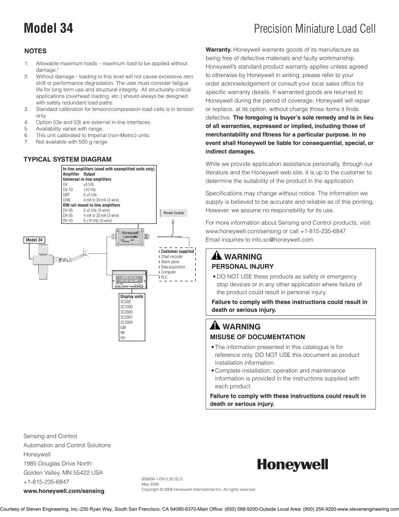
SensingandControl
AutomationandControlSolutions
Honeywell
1985DouglasDriveNorth
GoldenValley,MN55422USA
+1-815-235-6847
www.honeywell.com/sensing
008636-1-EN IL50 GLO May 2008Copyright © 2008 Honeywell International Inc. All rights reserved.
Model 34 Precision Miniature Load Cell
TYPICAL SYSTEM DIAGRAM
NOTES
1. Allowablemaximumloads–maximumloadtobeappliedwithoutdamage.2
2. Withoutdamage-loadingtothislevelwillnotcauseexcessivezeroshiftorperformancedegradation.Theusermustconsiderfatiguelifeforlongtermuseandstructuralintegrity.Allstructurallycriticalapplications(overheadloading,etc.)shouldalwaysbedesignedwithsafetyredundantloadpaths.
3. Standardcalibrationfortension/compressionloadcellsisintensiononly.
4. Option53eand53tareexternalin-lineinterfaces.5. Availabilityvarieswithrange.6. ThisunitcalibratedtoImperial(non-Metric)units.7. Notavailablewith500grange.
Warranty. Honeywellwarrantsgoodsofitsmanufactureasbeingfreeofdefectivematerialsandfaultyworkmanship.Honeywell’sstandardproductwarrantyappliesunlessagreedtootherwisebyHoneywellinwriting;pleaserefertoyourorderacknowledgementorconsultyourlocalsalesofficeforspecificwarrantydetails.IfwarrantedgoodsarereturnedtoHoneywellduringtheperiodofcoverage,Honeywellwillrepairorreplace,atitsoption,withoutchargethoseitemsitfindsdefective.The foregoing is buyer’s sole remedy and is in lieu of all warranties, expressed or implied, including those of merchantability and fitness for a particular purpose. In no event shall Honeywell be liable for consequential, special, or indirect damages.
Whileweprovideapplicationassistancepersonally,throughourliteratureandtheHoneywellwebsite,itisuptothecustomertodeterminethesuitabilityoftheproductintheapplication.
Specificationsmaychangewithoutnotice.Theinformationwesupplyisbelievedtobeaccurateandreliableasofthisprinting.However,weassumenoresponsibilityforitsuse.
FormoreinformationaboutSensingandControlproducts,visitwww.honeywell.com/sensingorcall+1-815-235-6847Emailinquiriestoinfo.sc@honeywell.com
WARNINGPERSONAL INJURY•DONOTUSEtheseproductsassafetyoremergencystopdevicesorinanyotherapplicationwherefailureoftheproductcouldresultinpersonalinjury.
Failure to comply with these instructions could result in death or serious injury.
WARNINGMISUSE OF DOCUMENTATION•Theinformationpresentedinthiscatalogueisforreferenceonly.DONOTUSEthisdocumentasproductinstallationinformation.•Completeinstallation,operationandmaintenanceinformationisprovidedintheinstructionssuppliedwitheachproduct.
Failure to comply with these instructions could result in death or serious injury.
Courtesy of Steven Engineering, Inc.-230 Ryan Way, South San Francisco, CA 94080-6370-Main Office: (650) 588-9200-Outside Local Area: (800) 258-9200-www.stevenengineering.com
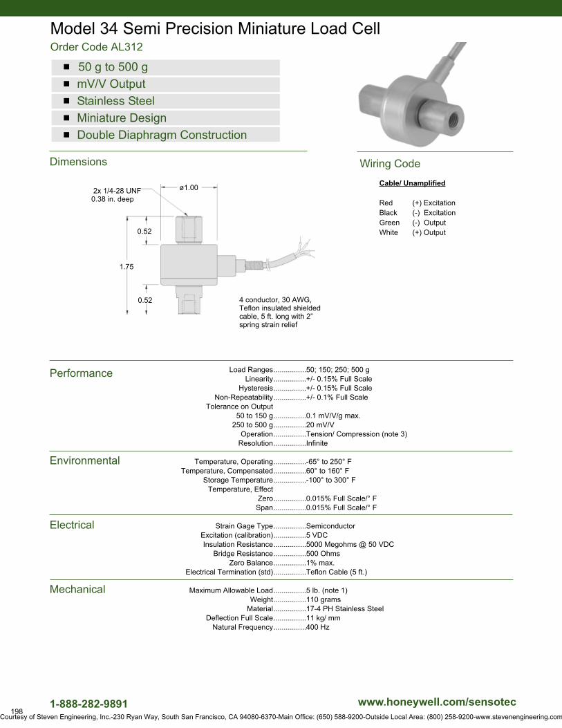
198
Dimensions
Performance
Environmental
Electrical
Mechanical
Model 34 Semi Precision Miniature Load CellOrder Code AL312
www.honeywell.com/sensotec
n 50 g to 500 gn mV/V Outputn Stainless Steeln Miniature Designn Double Diaphragm Construction
ø1.00
0.52
0.52
1.75
4 conductor, 30 AWG, Teflon insulated shieldedcable, 5 ft. long with 2”spring strain relief
2x 1/4-28 UNF0.38 in. deep
Load Ranges................50; 150; 250; 500 gLinearity................+/- 0.15% Full Scale
Hysteresis................+/- 0.15% Full Scale Non-Repeatability................+/- 0.1% Full Scale
Tolerance on Output 50 to 150 g................0.1 mV/V/g max.
250 to 500 g................20 mV/VOperation................Tension/ Compression (note 3)
Resolution................Infinite
Temperature, Operating................-65° to 250° FTemperature, Compensated................60° to 160° F
Storage Temperature................-100° to 300° FTemperature, Effect
Zero................0.015% Full Scale/° FSpan................0.015% Full Scale/° F
Strain Gage Type................SemiconductorExcitation (calibration)................5 VDCInsulation Resistance................5000 Megohms @ 50 VDC
Bridge Resistance................500 Ohms Zero Balance................1% max.
Electrical Termination (std)................Teflon Cable (5 ft.)
Maximum Allowable Load................5 lb. (note 1)Weight................110 grams
Material................17-4 PH Stainless SteelDeflection Full Scale................11 kg/ mm
Natural Frequency................400 Hz
Cable/ Unamplified
Red (+) ExcitationBlack (-) ExcitationGreen (-) OutputWhite (+) Output
1-888-282-9891
Wiring Code
Courtesy of Steven Engineering, Inc.-230 Ryan Way, South San Francisco, CA 94080-6370-Main Office: (650) 588-9200-Outside Local Area: (800) 258-9200-www.stevenengineering.com
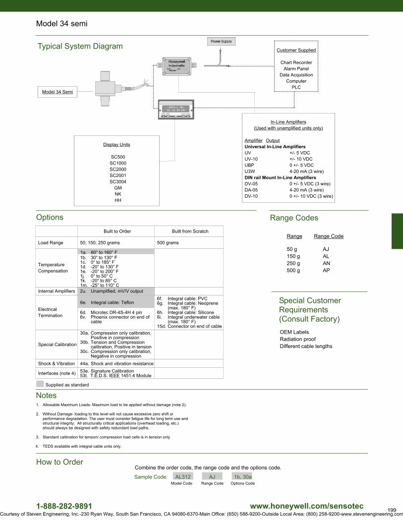
199www.honeywell.com/sensotec
Range Range Code
50 g AJ150 g AL250 g AN500 g AP
Range Codes
1-888-282-9891
In-Line Amplifiers(Used with unamplified units only)
Amplifier OutputUniversal In-Line AmplifiersUV +/- 5 VDCUV-10 +/- 10 VDCUBP 0 +/- 5 VDCU3W 4-20 mA (3 wire)DIN rail Mount In-Line AmplifiersDV-05 0 +/- 5 VDC (3 wire)DA-05 4-20 mA (3 wire)DV-10 0 +/- 10 VDC (3 wire)
Customer Supplied
Chart RecorderAlarm Panel
Data AcquisitionComputer
PLCModel 34 Semi
Model 34 semi
Model Code Range Code Options CodeSample Code: AL312 AJ 1b, 30a
Options
OEM LabelsRadiation proofDifferent cable lengths
Special Customer Requirements(Consult Factory)
Combine the order code, the range code and the options code.How to Order
Typical System Diagram
Display Units
SC500 SC1000 SC2000 SC2001 SC3004
GM NK HH
Notes
Built to Order Built from Scratch
Load Range 50; 150; 250 grams 500 grams
Temperature Compensation
1b. 30° to 130° F1c. 0° to 185° F1d. -20° to 130° F1e. -20° to 200° F1j. 0° to 50° C1k. -20° to 85° C1m. -25° to 110° C
Internal Amplifiers 2u. Unamplified, mV/V output
ElectricalTermination
6d. Microtec DR-4S-4H 4 pin6v. Phoenix connector on end of
cable
6f. Integral cable: PVC6g. Integral cable: Neoprene
(max. 180° F)6h. Integral cable: Silicone6i. Integral underwater cable
(max. 180° F)15d. Connector on end of cable
Special Calibration
30a. Compression only calibration, Positive in compression
30b. Tension and Compression calibration, Positive in tension
30c. Compression only calibration, Negative in compression
Shock & Vibration 44a. Shock and vibration resistance
Interfaces (note 4) 53e. Signature Calibration 53t. T.E.D.S. IEEE 1451.4 Module
Supplied as standard
6e. Integral cable: Teflon
1a. 60° to 160° F
1. Allowable Maximum Loads- Maximum load to be applied without damage (note 2).
2. Without Damage- loading to this level will not cause excessive zero shift or performance degradation. The user must consider fatigue life for long term use and structural integrity. All structurally critical applications (overhead loading, etc.) should always be designed with safety redundant load paths.
3. Standard calibration for tension/ compression load cells is in tension only
4. TEDS available with integral cable units only.
Courtesy of Steven Engineering, Inc.-230 Ryan Way, South San Francisco, CA 94080-6370-Main Office: (650) 588-9200-Outside Local Area: (800) 258-9200-www.stevenengineering.com

Subminiature Load CellModel 11
DESCRIPTIONModel 11 (tension/compression) subminiature load cell is
designed to measure load ranges from 150 g to 1000 lb. With
subminiature dimensions, including diameters from .50 in to 0.75
in and height of 0.38 in, these units are easily incorporated into
systems having limited space.
The model achieves a non-linearity and hysteresis of 0.5 % full
scale respectively and a frequency response of up to 58 kHz. A
balance module is included in the load cell’s lead wire cable for
zero balance, and should not be removed.
FEATURES• 150gto1000lb
• mV/Voutput
• Subminiaturedesign
• Singlediaphragmconstruction
Courtesy of Steven Engineering, Inc.-230 Ryan Way, South San Francisco, CA 94080-6370-Main Office: (650) 588-9200-Outside Local Area: (800) 258-9200-www.stevenengineering.com
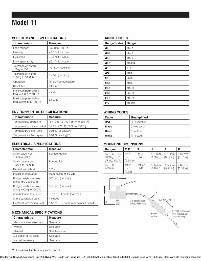
2Honeywell•SensingandControl
Model 11
PERFORMANCE SPECIFICATIONS
Characteristic Measure
Load ranges7 150 g to 1000 lb
Linearity ±0.5 % full scale
Hysteresis ±0.5 % full scale
Non-repeatability ±0.1 % full scale
Tolerance on output 150 g to 500 g
10mV/V(nominal)
Tolerance on output1000 g to 1000 lb
2mV/V(nominal)
Operation Tension/compression3
Resolution Infinite
Maximum permissible torque 150 g to 100 lb
4 in-lb
Maximum permissible torque 250 lb to 1000 lb
20 in-lb
RANGE CODES
Range codes Range
AL 150 g
AN 250 g
AP 500 g
AR 1000 g
AT 5 lb
AV 10 lb
BL 25 lb
BN 50 lb
BR 100 lb
CN 250 lb
CR 500 lb
CV 1000 lb
ELECTRICAL SPECIFICATIONS
Characteristic Measure
Straingagetype150 g to 500 g
Semiconductor
Straingagetype 1000 g to 1000 lb
Bonded foil
Excitation (calibration) 5Vdc
Insulation resistance 5000mOhm@50Vdc
Bridge resistance (toler-ance) 150 g to 500 g
500 ohm (nominal)
Bridge resistance (toler-ance) 1000 g to 1000 lb
350 ohm (nominal)
Zero balance (tolerance) ±3 % of full scale (nominal)
Shuntcalibrationdata Included
Electrical termination (std) 1,83 m [5 ft] cable with balance board4
MECHANICAL SPECIFICATIONS
Characteristic Measure
Maximum allowable load Seetable1
Weight Seetable
Material Stainlesssteel
Deflection @ full scale Seetable
Natural frequency Seetable
WIRING CODES
Cable Unamplified
Red (+) excitation
Black (-) excitation
Green (-) output
White (+) output
MOUNTING DIMENSIONS
Ranges Ø D T H A B
150, 250, 500, 1000 g; 5, 10, 25, 50, 100 lb
12,7 mm[0.50 in]
#4-40 UNC
7,37 mm [0.29 in]
4,83 mm [0.19 in]
4,57 mm[0.18 in]
250, 500, 1000 lb
19,05 mm[0.75]
1/4-28 UNF
9,65 mm[0.38 in]
7,87 mm [0.31 in]
7,87 mm [0.31 in]
ENVIRONMENTAL SPECIFICATIONS
Characteristic Measure
Temperature, operating -54°Cto121°C[-65°Fto250°F]
Temperature, compensated 15°Cto71°C[60°Fto160°F]
Temperature effect, zero 0.01 % full scale/°F
Temperature effect, span 0.02 % reading/°F
Courtesy of Steven Engineering, Inc.-230 Ryan Way, South San Francisco, CA 94080-6370-Main Office: (650) 588-9200-Outside Local Area: (800) 258-9200-www.stevenengineering.com
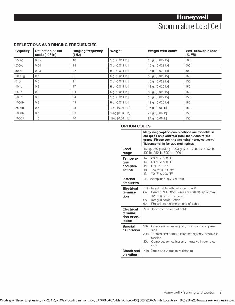
Honeywell•SensingandControl3
Subminiature Load Cell
DEFLECTIONS AND RINGING FREQUENCIES
Capacity Deflection at full scale (10-3 in)
Ringing frequency (kHz)
Weight Weight with cable Max. allowable load1 (% FS)
150 g 0.05 10 5 g [0.011 lb] 13 g [0.029 lb] 500
250 g 0.04 14 5 g [0.011 lb] 13 g [0.029 lb] 500
500 g 0.03 22 5 g [0.011 lb] 13 g [0.029 lb] 500
1000 g 0.7 8 5 g [0.011 lb] 13 g [0.029 lb] 150
5 lb 0.6 11 5 g [0.011 lb] 13 g [0.029 lb] 150
10 lb 0.6 17 5 g [0.011 lb] 13 g [0.029 lb] 150
25 lb 0.5 24 5 g [0.011 lb] 13 g [0.029 lb] 150
50 lb 0.5 34 5 g [0.011 lb] 13 g [0.029 lb] 150
100 lb 0.5 48 5 g [0.011 lb] 13 g [0.029 lb] 150
250 lb 0.6 25 19 g [0.041 lb] 27 g [0.06 lb] 150
500 lb 0.7 33 19 g [0.041 lb] 27 g [0.06 lb] 150
1000 lb 1.0 40 19 g [0.041 lb] 27 g [0.06 lb] 150
OPTION CODESMany range/option combinations are available in our quick-ship and fast-track manufacture pro-grams. Please see http://sensing.honeywell.com/TMsensor-ship for updated listings.
Load range
150 g, 250 g, 500 g, 1000 g, 5 lb, 10 lb, 25 lb, 50 lb, 100 lb, 250 lb, 500 lb, 1000 lb
Tempera-turecompen-sation
1a. 60 °F to 160 °F1b. 30 °F to 130 °F1c. 0 °F to 185 °F1e. -20 °F to 200 °F5
1f. 70 °F to 250 °F5
Internal amplifiers
2u.Unamplified,mV/Voutput
Electrical termina-tion
5 ft integral cable with balance board4
6a. Bendix PTIH-10-6P - (or equivalent) 6 pin (max. 120°C)onendofcable
6e. Integral cable: Teflon6v. Phoenix connector on end of cable
Electrical termina-tion orien-tation
15d.Connectoronendofcable
Special calibration
30a.Compressiontestingonly,positiveincompres-sion
30b. Tension and compression testing only, positive in tension
30c. Compressiontestingonly,negativeincompres-sion
Shock and vibration
44a.Shockandvibrationresistance
Courtesy of Steven Engineering, Inc.-230 Ryan Way, South San Francisco, CA 94080-6370-Main Office: (650) 588-9200-Outside Local Area: (800) 258-9200-www.stevenengineering.com
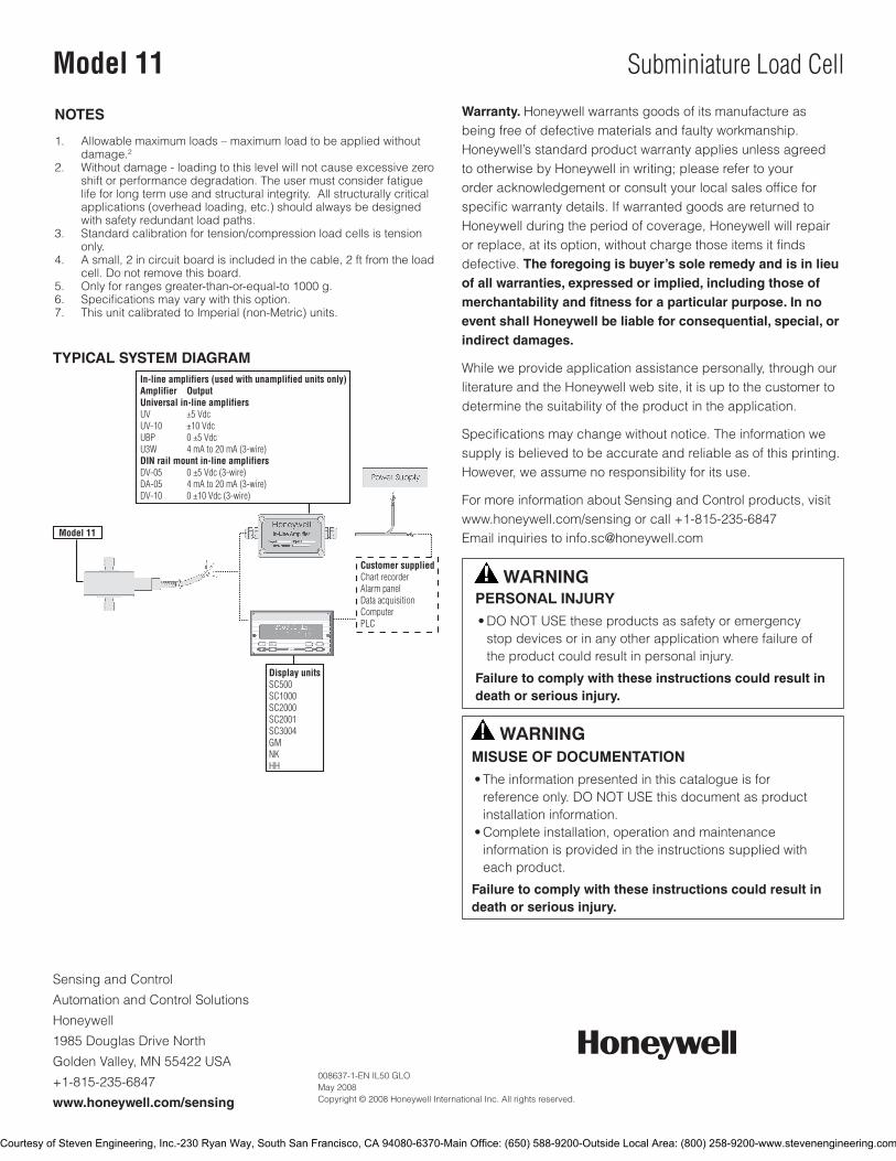
SensingandControl
AutomationandControlSolutions
Honeywell
1985 Douglas Drive North
GoldenValley,MN55422USA
+1-815-235-6847
www.honeywell.com/sensing
008637-1-EN IL50 GLO May 2008Copyright © 2008 Honeywell International Inc. All rights reserved.
Model 11 Subminiature Load Cell
TYPICAL SYSTEM DIAGRAM
NOTES
1. Allowable maximum loads – maximum load to be applied without damage.2
2. Without damage - loading to this level will not cause excessive zero shift or performance degradation. The user must consider fatigue life for long term use and structural integrity. All structurally critical applications (overhead loading, etc.) should always be designed with safety redundant load paths.
3. Standardcalibrationfortension/compressionloadcellsistensiononly.
4. A small, 2 in circuit board is included in the cable, 2 ft from the load cell. Do not remove this board.
5. Only for ranges greater-than-or-equal-to 1000 g.6. Specificationsmayvarywiththisoption.7. This unit calibrated to Imperial (non-Metric) units.
Warranty. Honeywell warrants goods of its manufacture as being free of defective materials and faulty workmanship. Honeywell’s standard product warranty applies unless agreed to otherwise by Honeywell in writing; please refer to your order acknowledgement or consult your local sales office for specific warranty details. If warranted goods are returned to Honeywell during the period of coverage, Honeywell will repair or replace, at its option, without charge those items it finds defective. The foregoing is buyer’s sole remedy and is in lieu of all warranties, expressed or implied, including those of merchantability and fitness for a particular purpose. In no event shall Honeywell be liable for consequential, special, or indirect damages.
While we provide application assistance personally, through our literature and the Honeywell web site, it is up to the customer to determine the suitability of the product in the application.
Specificationsmaychangewithoutnotice.Theinformationwesupply is believed to be accurate and reliable as of this printing. However, we assume no responsibility for its use.
FormoreinformationaboutSensingandControlproducts,visitwww.honeywell.com/sensing or call +1-815-235-6847Email inquiries to [email protected]
WARNINGPERSONAL INJURY•DONOTUSEtheseproductsassafetyoremergencystopdevicesorinanyotherapplicationwherefailureoftheproductcouldresultinpersonalinjury.
Failure to comply with these instructions could result in death or serious injury.
WARNINGMISUSE OF DOCUMENTATION•Theinformationpresentedinthiscatalogueisforreferenceonly.DONOTUSEthisdocumentasproductinstallationinformation.•Completeinstallation,operationandmaintenanceinformationisprovidedintheinstructionssuppliedwitheachproduct.
Failure to comply with these instructions could result in death or serious injury.
Courtesy of Steven Engineering, Inc.-230 Ryan Way, South San Francisco, CA 94080-6370-Main Office: (650) 588-9200-Outside Local Area: (800) 258-9200-www.stevenengineering.com
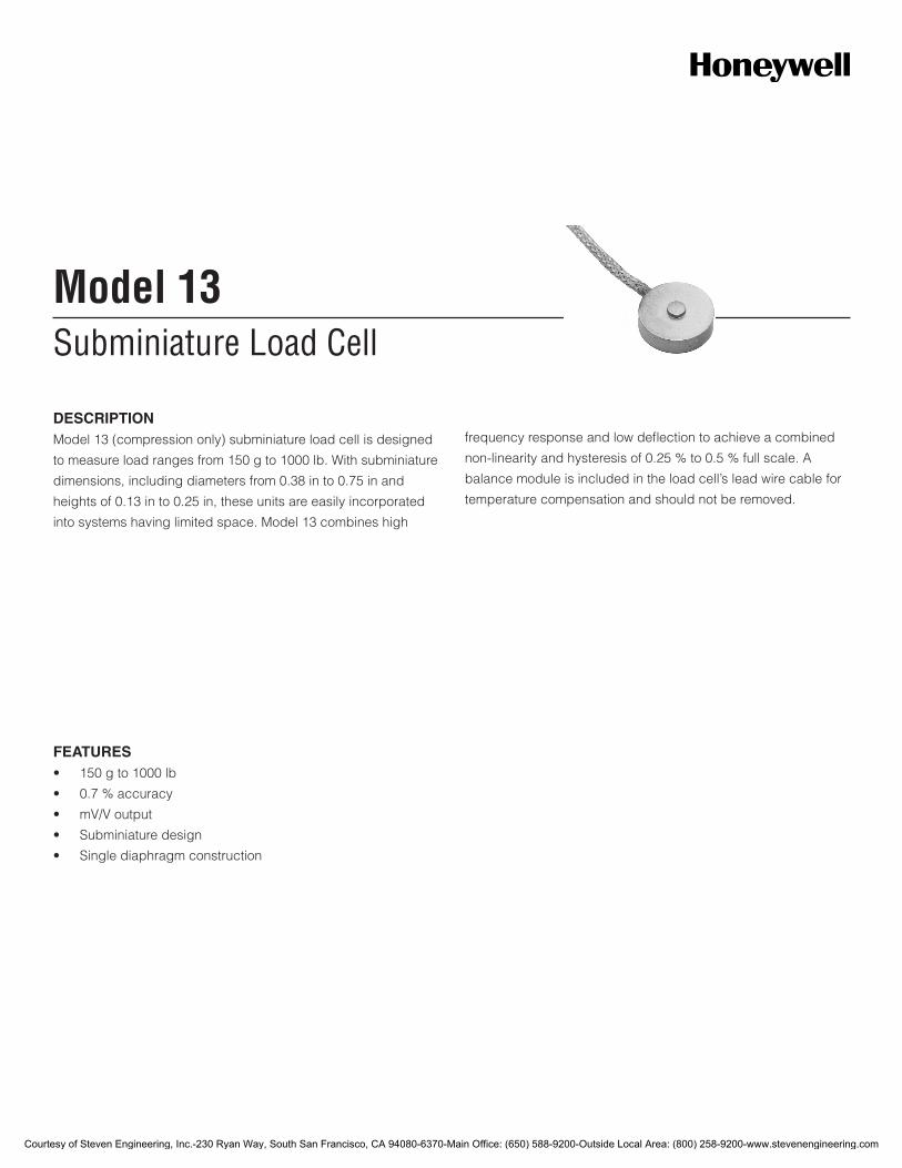
Subminiature Load CellModel 13
DESCRIPTIONModel 13 (compression only) subminiature load cell is designed
to measure load ranges from 150 g to 1000 lb. With subminiature
dimensions, including diameters from 0.38 in to 0.75 in and
heights of 0.13 in to 0.25 in, these units are easily incorporated
into systems having limited space. Model 13 combines high
frequency response and low deflection to achieve a combined
non-linearity and hysteresis of 0.25 % to 0.5 % full scale. A
balance module is included in the load cell’s lead wire cable for
temperature compensation and should not be removed.
FEATURES• 150gto1000lb
• 0.7%accuracy
• mV/Voutput
• Subminiaturedesign
• Singlediaphragmconstruction
Courtesy of Steven Engineering, Inc.-230 Ryan Way, South San Francisco, CA 94080-6370-Main Office: (650) 588-9200-Outside Local Area: (800) 258-9200-www.stevenengineering.com
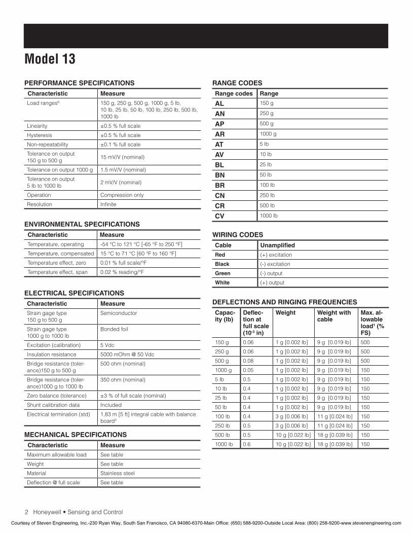
2Honeywell•SensingandControl
Model 13
PERFORMANCE SPECIFICATIONS
Characteristic Measure
Load ranges6 150 g, 250 g, 500 g, 1000 g, 5 lb, 10 lb, 25 lb, 50 lb, 100 lb, 250 lb, 500 lb, 1000 lb
Linearity ±0.5 % full scale
Hysteresis ±0.5 % full scale
Non-repeatability ±0.1 % full scale
Tolerance on output 150 g to 500 g
15mV/V(nominal)
Tolerance on output 1000 g 1.5mV/V(nominal)
Tolerance on output5 lb to 1000 lb
2mV/V(nominal)
Operation Compressiononly
Resolution Infinite
RANGE CODES
Range codes Range
AL 150 g
AN 250 g
AP 500 g
AR 1000 g
AT 5 lb
AV 10 lb
BL 25 lb
BN 50 lb
BR 100 lb
CN 250 lb
CR 500 lb
CV 1000 lb
ELECTRICAL SPECIFICATIONS
Characteristic Measure
Straingagetype150 g to 500 g
Semiconductor
Straingagetype1000 g to 1000 lb
Bonded foil
Excitation (calibration) 5Vdc
Insulation resistance 5000mOhm@50Vdc
Bridge resistance (toler-ance)150 g to 500 g
500 ohm (nominal)
Bridge resistance (toler-ance)1000 g to 1000 lb
350 ohm (nominal)
Zero balance (tolerance) ±3 % of full scale (nominal)
Shuntcalibrationdata Included
Electrical termination (std) 1,83 m [5 ft] integral cable with balance board3
MECHANICAL SPECIFICATIONS
Characteristic Measure
Maximum allowable load Seetable
Weight Seetable
Material Stainlesssteel
Deflection @ full scale Seetable
WIRING CODES
Cable Unamplified
Red (+) excitation
Black (-) excitation
Green (-) output
White (+) output
DEFLECTIONS AND RINGING FREQUENCIES
Capac-ity (lb)
Deflec-tion at full scale (10-3 in)
Weight Weight with cable
Max. al-lowable load1 (% FS)
150 g 0.06 1 g [0.002 lb] 9 g [0.019 lb] 500
250 g 0.06 1 g [0.002 lb] 9 g [0.019 lb] 500
500 g 0.08 1 g [0.002 lb] 9 g [0.019 lb] 500
1000 g 0.05 1 g [0.002 lb] 9 g [0.019 lb] 150
5 lb 0.5 1 g [0.002 lb] 9 g [0.019 lb] 150
10 lb 0.4 1 g [0.002 lb] 9 g [0.019 lb] 150
25 lb 0.4 1 g [0.002 lb] 9 g [0.019 lb] 150
50 lb 0.4 1 g [0.002 lb] 9 g [0.019 lb] 150
100 lb 0.4 3 g [0.006 lb] 11 g [0.024 lb] 150
250 lb 0.5 3 g [0.006 lb] 11 g [0.024 lb] 150
500 lb 0.5 10 g [0.022 lb] 18 g [0.039 lb] 150
1000 lb 0.6 10 g [0.022 lb] 18 g [0.039 lb] 150
ENVIRONMENTAL SPECIFICATIONS
Characteristic Measure
Temperature, operating -54°Cto121°C[-65°Fto250°F]
Temperature, compensated 15°Cto71°C[60°Fto160°F]
Temperature effect, zero 0.01%fullscale/°F
Temperature effect, span 0.02%reading/°F
Courtesy of Steven Engineering, Inc.-230 Ryan Way, South San Francisco, CA 94080-6370-Main Office: (650) 588-9200-Outside Local Area: (800) 258-9200-www.stevenengineering.com
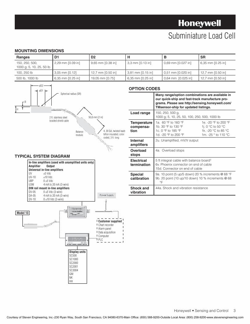
Honeywell•SensingandControl3
Subminiature Load Cell
MOUNTING DIMENSIONS
Ranges D1 D2 H B SR
150, 250, 500, 1000 g; 5, 10, 25, 50 lb
2,29 mm [0.09 in] 9,65 mm [0.38 in] 3,3 mm [0.13 in] 0,69 mm [0.027 in] 6,35 mm [0.25 in]
100, 250 lb 3,05 mm [0.12] 12,7 mm [0.50 in] 3,81 mm [0.15 in] 0,51 mm [0.020 in] 12,7 mm [0.50 in]
500 lb, 1000 lb 6,35 mm [0.25 in] 19,05 mm [0.75] 6,35 mm [0.25 in] 0,64 mm [0.025 in] 12,7 mm [0.50 in]
OPTION CODES
Many range/option combinations are available in our quick-ship and fast-track manufacture pro-grams. Please see http://sensing.honeywell.com/TMsensor-ship for updated listings.
Load range 150, 250, 500 g, 1000 g; 5, 10, 25, 50, 100, 250, 500, 1000 lb
Temperaturecompensa-tion
1a.60°Fto160°F1b.30°Fto130°F1c.0°Fto185°F1d.-20°Fto200°F
1e.-20°Fto200°F1j.0°Cto50°C1k.-20°Cto85°C1m.-25°to110°C
Internal amplifiers
2u.Unamplified,mV/Voutput
Overload stops
4a. Overload stops
Electrical termination
5 ft integral cable with balance board3
6v. Phoenix connector on end of cable15d.Connectoronendofcable
Special calibration
9a.10point(5up/5down)20%increments@68°F9b.20point(10up/10down)10%increments@68
°F
Shock and vibration
44a.Shockandvibrationresistance
TYPICAL SYSTEM DIAGRAM
Courtesy of Steven Engineering, Inc.-230 Ryan Way, South San Francisco, CA 94080-6370-Main Office: (650) 588-9200-Outside Local Area: (800) 258-9200-www.stevenengineering.com
008641-2-EN IL50 GLO April 2009Copyright © 2009 Honeywell International Inc. All rights reserved.
Model 13 Subminiature Load Cell
Sensing and Control
Honeywell
1985 Douglas Drive North
Golden Valley, MN 55422
www.honeywell.com
NOTES
1. Allowable maximum loads – maximum load to be applied without damage.2 Loads described allow for 100 % full scale axial loading with the bending loads specified. Torque loading maximum is with-outaxialorotherload.Foranyothercombination,consultfactory.
2. Without damage - loading to this level will not cause excessive zero shift or performance degradation. The user must consider fatigue life for long term use and structural integrity. All structurally critical applications (overhead loading, etc.) should always be designed with safety redundant load paths.
3. A small, 2 in circuit board is included in the cable, 2 ft from the load cell. Do not remove this board.
4. Only for ranges greater-than-or-equal-to 1000 g.5. Specificationsmayvarywiththisoption.6. This unit calibrated to Imperial (non-Metric) units.
Warranty. Honeywell warrants goods of its manufacture as being free of defective materials and faulty workmanship. Honeywell’s standard product warranty applies unless agreed to otherwise by Honeywell in writing; please refer to your order acknowledgement or consult your local sales office for specific warranty details. If warranted goods are returned to Honeywell during the period of coverage, Honeywell will repair or replace, at its option, without charge those items it finds defective. The foregoing is buyer’s sole remedy and is in lieu of all warranties, expressed or implied, including those of merchantability and fitness for a particular purpose. In no event shall Honeywell be liable for consequential, special, or indirect damages.
While we provide application assistance personally, through our literature and the Honeywell web site, it is up to the customer to determine the suitability of the product in the application.
WARNINGPERSONAL INJURY
•DONOTUSEtheseproductsassafetyoremergencystop devices or in any other application where failure of the product could result in personal injury.
Failure to comply with these instructions could result in death or serious injury.
WARNINGMISUSE OF DOCUMENTATION
•Theinformationpresentedinthisdatasheetisforreferenceonly.DONOTUSEthisdocumentasproductinstallation information.
•Completeinstallation,operationandmaintenanceinformation is provided in the instructions supplied with each product.
Failure to comply with these instructions could result in death or serious injury.
Find out more
Honeywell serves its customers
through a worldwide network of
sales offices, representatives
anddistributors.Forapplication
assistance, current specifica-
tions, pricing or name of the
nearest Authorized Distributor,
contact your local sales office.
To learn more about Honeywell’s
test and measurement products,
call +1-614-850-5000, visit
www.honeywell.com/sensotec,
or e-mail inquiries to
Courtesy of Steven Engineering, Inc.-230 Ryan Way, South San Francisco, CA 94080-6370-Main Office: (650) 588-9200-Outside Local Area: (800) 258-9200-www.stevenengineering.com

Top Hat Subminiature Load CellModel LFH-7I
DESCRIPTIONModel LFH-7I subminiature load cell is a low profile force
transducer for applications with minimal space and high
capacity requirements. This transducer utilizes foil strain gages
to measure compression loads of up to 10,000 lb and achieves
accuracy of ±0.7 % full scale. The top of the load cell is the area
where the force is applied and the base ring of the load cell
must be placed on a hard, machine-ground flat surface to obtain
optimum accuracy.
FEATURES• 250lbto10000lbrange
• ±0.7%accuracy
• Stainlesssteel
• Columnconstruction
• mV/Voutput
Courtesy of Steven Engineering, Inc.-230 Ryan Way, South San Francisco, CA 94080-6370-Main Office: (650) 588-9200-Outside Local Area: (800) 258-9200-www.stevenengineering.com
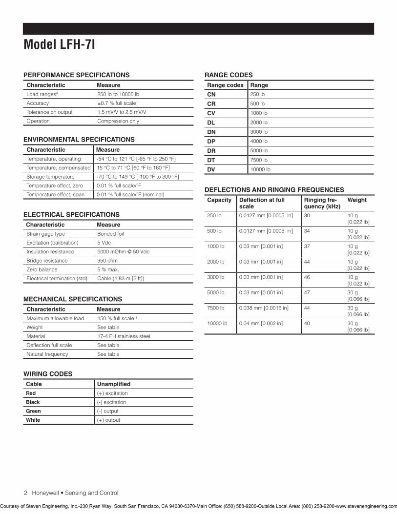
2Honeywell•SensingandControl
Model LFH-7I
PERFORMANCE SPECIFICATIONS
Characteristic Measure
Load ranges4 250lbto10000lb
Accuracy ±0.7 % full scale1
Tolerance on output 1.5mV/Vto2.5mV/V
Operation Compressiononly
RANGE CODES
Range codes Range
CN 250lb
CR 500lb
CV 1000 lb
DL 2000lb
DN 3000 lb
DP 4000 lb
DR 5000lb
DT 7500lb
DV 10000 lb
ELECTRICAL SPECIFICATIONS
Characteristic Measure
Straingagetype Bonded foil
Excitation (calibration) 5Vdc
Insulation resistance 5000mOhm@50Vdc
Bridge resistance 350ohm
Zero balance 5%max.
Electrical termination (std) Cable(1,83m[5ft])
MECHANICAL SPECIFICATIONS
Characteristic Measure
Maximum allowable load 150%fullscale2
Weight Seetable
Material 17-4 PH stainless steel
Deflection full scale Seetable
Natural frequency Seetable
WIRING CODES
Cable Unamplified
Red (+) excitation
Black (-) excitation
Green (-) output
White (+) output
ENVIRONMENTAL SPECIFICATIONS
Characteristic Measure
Temperature, operating -54°Cto121°C[-65°Fto250°F]
Temperature, compensated 15°Cto71°C[60°Fto160°F]
Storagetemperature -70°Cto149°C[-100°Fto300°F]
Temperature effect, zero 0.01%fullscale/°F
Temperature effect, span 0.01%fullscale/°F(nominal)DEFLECTIONS AND RINGING FREQUENCIES
Capacity Deflection at full scale
Ringing fre-quency (kHz)
Weight
250lb 0,0127mm[0.0005in] 30 10 g [0.022lb]
500lb 0,0127mm[0.0005in] 34 10 g [0.022lb]
1000 lb 0,03mm[0.001in] 37 10 g [0.022lb]
2000lb 0,03mm[0.001in] 44 10 g [0.022lb]
3000 lb 0,03mm[0.001in] 46 10 g [0.022lb]
5000lb 0,03mm[0.001in] 47 30 g [0.066lb]
7500lb 0,038mm[0.0015in] 44 30 g [0.066lb]
10000 lb 0,04mm[0.002in] 40 30 g [0.066lb]
Courtesy of Steven Engineering, Inc.-230 Ryan Way, South San Francisco, CA 94080-6370-Main Office: (650) 588-9200-Outside Local Area: (800) 258-9200-www.stevenengineering.com

Honeywell•SensingandControl3
Top Hat Subminiature Load Cell
MOUNTING DIMENSIONS
Ranges ØD1 mm [in] ØD2 mm [in] H mm [in] F mm [in] W mm [in]
250lb 12,7[0.50] 6,86[0.27] 9,65[0.38] 3,3[0.13] 10,92[0.43]
500lb 12,7[0.50] 7,11[0.28] 9,65[0.38] 3,3[0.13] 10,92[0.43]
1000 lb 12,7[0.50] 7,87[0.31] 9,65[0.38] 3,3[0.13] 10,92[0.43]
2000lb 12,7[0.50] 10,41[0.41] 9,65[0.38] 3,3[0.13] 10,92[0.43]
3000 lb 12,7[0.50] 11,43[0.45] 9,65[0.38] 3,3[0.13] 11,68[0.46]
5000lb 16,00[0.63] 13,46[0.53] 15,24[0.60] 5,84[0.23] 12,95[0.51]
7500lb 22,35[0.88] 16,00[0.63] 16,00[0.63] 13,72[0.54] 16,00[0.63]
10000 lb 22,35[0.88] 16,00[0.63] 16,00[0.63] 13,72[0.54] 16,00[0.63]
OPTION CODESMany range/option combinations are available in our quick-ship and fast-track manufacture pro-grams. Please see http://sensing.honeywell.com/TMsensor-ship for updated listings.
Load range
250,500,1000,2000,3000,4000,5000,7500,10000lb
Tempera-turecompen-sation
1a.60°Fto160°F1b.30°Fto130°F1c.0°Fto185°F1d.-20°Fto130°F1e.-20°Fto200°F1f.70°Fto250°F1j.0°Cto50°C1k.-20°Cto85°C1m.-25°Cto110°C
Internal amplifiers
2u.Unamplified,mV/Voutput
Electrical termina-tion
6e.Integralcable:Teflon6h.Integralcable:Silicone6v.Phoenixconnectoronendofcable15d.Connectoronendofcable
Special calibration
9a.10point(5up/5down)20%increments@70°F9b.20point(10up/10down)10%increments@70°F
Shock and vibration
44a.Shockandvibrationresistance
Courtesy of Steven Engineering, Inc.-230 Ryan Way, South San Francisco, CA 94080-6370-Main Office: (650) 588-9200-Outside Local Area: (800) 258-9200-www.stevenengineering.com
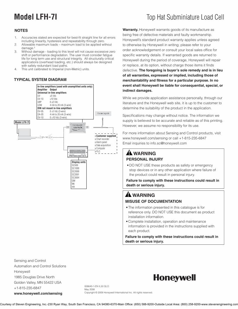
SensingandControl
AutomationandControlSolutions
Honeywell
1985DouglasDriveNorth
GoldenValley,MN55422USA
+1-815-235-6847
www.honeywell.com/sensing
008640-1-EN IL50 GLO May 2008Copyright © 2008 Honeywell International Inc. All rights reserved.
Model LFH-7I Top Hat Subminiature Load Cell
TYPICAL SYSTEM DIAGRAM
NOTES
1. Accuracies stated are expected for best-fit straight line for all errors including linearity, hysteresis and repeatability through zero.
2. Allowablemaximumloads–maximumloadtobeappliedwithoutdamage.3
3. Without damage - loading to this level will not cause excessive zero shift or performance degradation. The user must consider fatigue life for long term use and structural integrity. All structurally critical applications (overhead loading, etc.) should always be designed with safety redundant load paths.
4. This unit calibrated to Imperial (non-Metric) units.
Warranty. Honeywell warrants goods of its manufacture as being free of defective materials and faulty workmanship. Honeywell’s standard product warranty applies unless agreed to otherwise by Honeywell in writing; please refer to your order acknowledgement or consult your local sales office for specific warranty details. If warranted goods are returned to Honeywell during the period of coverage, Honeywell will repair or replace, at its option, without charge those items it finds defective. The foregoing is buyer’s sole remedy and is in lieu of all warranties, expressed or implied, including those of merchantability and fitness for a particular purpose. In no event shall Honeywell be liable for consequential, special, or indirect damages.
While we provide application assistance personally, through our literature and the Honeywell web site, it is up to the customer to determine the suitability of the product in the application.
Specificationsmaychangewithoutnotice.Theinformationwesupply is believed to be accurate and reliable as of this printing. However, we assume no responsibility for its use.
FormoreinformationaboutSensingandControlproducts,visitwww.honeywell.com/sensingorcall+1-815-235-6847Emailinquiriestoinfo.sc@honeywell.com
WARNINGPERSONAL INJURY
•DONOTUSEtheseproductsassafetyoremergencystopdevicesorinanyotherapplicationwherefailureoftheproductcouldresultinpersonalinjury.
Failure to comply with these instructions could result in death or serious injury.
WARNINGMISUSE OF DOCUMENTATION
•Theinformationpresentedinthiscatalogueisforreferenceonly.DONOTUSEthisdocumentasproductinstallationinformation.•Completeinstallation,operationandmaintenanceinformationisprovidedintheinstructionssuppliedwitheachproduct.
Failure to comply with these instructions could result in death or serious injury.
Courtesy of Steven Engineering, Inc.-230 Ryan Way, South San Francisco, CA 94080-6370-Main Office: (650) 588-9200-Outside Local Area: (800) 258-9200-www.stevenengineering.com
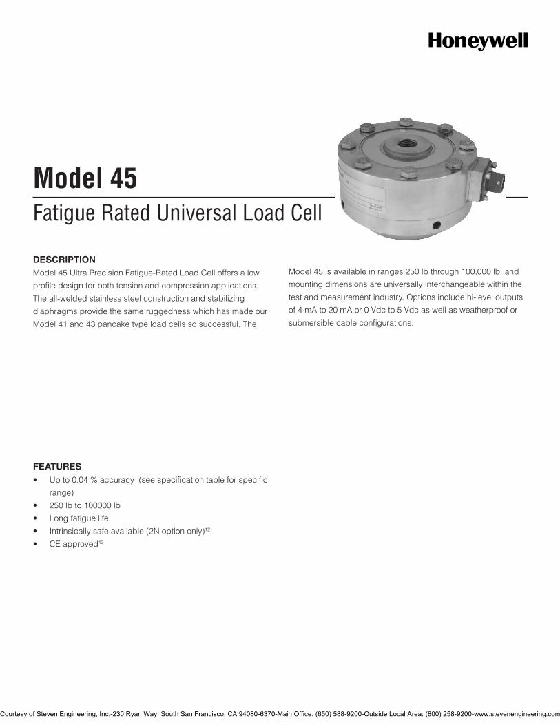
Fatigue Rated Universal Load CellModel 45
DESCRIPTIONModel 45 Ultra Precision Fatigue-Rated Load Cell offers a low
profile design for both tension and compression applications.
The all-welded stainless steel construction and stabilizing
diaphragms provide the same ruggedness which has made our
Model 41 and 43 pancake type load cells so successful. The
Model 45 is available in ranges 250 lb through 100,000 lb. and
mounting dimensions are universally interchangeable within the
test and measurement industry. Options include hi-level outputs
of 4 mA to 20 mA or 0 Vdc to 5 Vdc as well as weatherproof or
submersible cable configurations.
FEATURES• Upto0.04%accuracy(seespecificationtableforspecific
range)
• 250lbto100000lb
• Longfatiguelife
• Intrinsicallysafeavailable(2Noptiononly)12
• CEapproved13
Courtesy of Steven Engineering, Inc.-230 Ryan Way, South San Francisco, CA 94080-6370-Main Office: (650) 588-9200-Outside Local Area: (800) 258-9200-www.stevenengineering.com
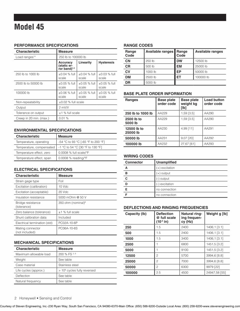
2Honeywell•SensingandControl
Model 45
PERFORMANCE SPECIFICATIONS
Characteristic Measure
Load ranges14 250 lb to 100000 lb
Accuracy (static er-ror band)1,2
Linearity Hysteresis
250 lb to 1000 lb ±0.04%fullscale
±0.04%fullscale
±0.03%fullscale
2500 lb to 50000 lb ±0.05%fullscale
±0.05%fullscale
±0.05%fullscale
100000 lb ±0.06%fullscale
±0.05%fullscale
±0.05%fullscale
Non-repeatability ±0.02%fullscale
Output 2 mV/V
Tolerance on output ±1%fullscale
Creepin20min.(max.) 0.01%
ENVIRONMENTAL SPECIFICATIONS
Characteristic Measure
Temperature, operating -54 °C to 93 °C [-65 °F to 200 °F]
Temperature, compensated -1 °C to 54 °C [30 °F to 130 °F]
Temperature effect, zero 0.0008%fullscale/°F
Temperature effect, span 0.0008%reading/°F
ELECTRICAL SPECIFICATIONS
Characteristic Measure
Straingagetype Foil
Excitation(calibration) 10 Vdc
Excitation(acceptable) 20 Vdc
Insulationresistance 5000 mOhm @ 50 V
Bridge resistance (tolerance)
350ohm(nominal)8
Zerobalance(tolerance) ±1%fullscale
Shuntcalibrationdata Included
Electricaltermination(std) PC02A-10-6P
Mating connector (notincluded)
PC06A-10-6S
MECHANICAL SPECIFICATIONS
Characteristic Measure
Maximumallowableload 200%FS3, 9
Weight Seetable
Case material Stainlesssteel
Lifecycles(approx.) > 108 cycles fully reversed
Deflection Seetable
Naturalfrequency Seetable
RANGE CODES
Range Code
Available ranges Range Code
Available ranges
CN 250 lb DW 12500 lb
CR 500 lb EM 25000 lb
CV 1000 lb EP 50000 lb
DM 2500 lb ET 100000 lb
DR 5000 lb
WIRING CODES
Connector Unamplified
A (+)excitation
B (+)output
C (-)output
D (-)excitation
E no connection
F no connection
BASE PLATE ORDER INFORMATION
Ranges Base plate order code
Base plate weight kg [lb]
Load button order code
250 lb to 1000 lb AA229 1,59 [3.5] AA290
2500 lb to 5000 lb
AA229 1,59 [3.5] AA290
12500 lb to 25000 lb
AA230 4,99 [11] AA291
50000 lb AA231 9,07 [20] AA292
100000 lb AA232 27,67 [61] AA293
DEFLECTIONS AND RINGING FREQUENCIES
Capacity (lb) Deflection @ full scale (10-3 in)
Natural ring-ing frequen-cy (Hz)
Weight g [lb]
250 1.5 2400 1406,1 [3.1]
500 1.5 2400 1406,1 [3.1]
1000 1.5 3400 1406,1 [3.1]
2500 1 6800 1451,5 [3.2]
5000 1 9100 1451,5 [3.2]
12500 2 5700 3994,6 [8.8]
25000 2 7000 3994,6 [8.8]
50000 2 6300 9979 [22]
100000 2.5 4500 24947,58 [55]
Courtesy of Steven Engineering, Inc.-230 Ryan Way, South San Francisco, CA 94080-6370-Main Office: (650) 588-9200-Outside Local Area: (800) 258-9200-www.stevenengineering.com
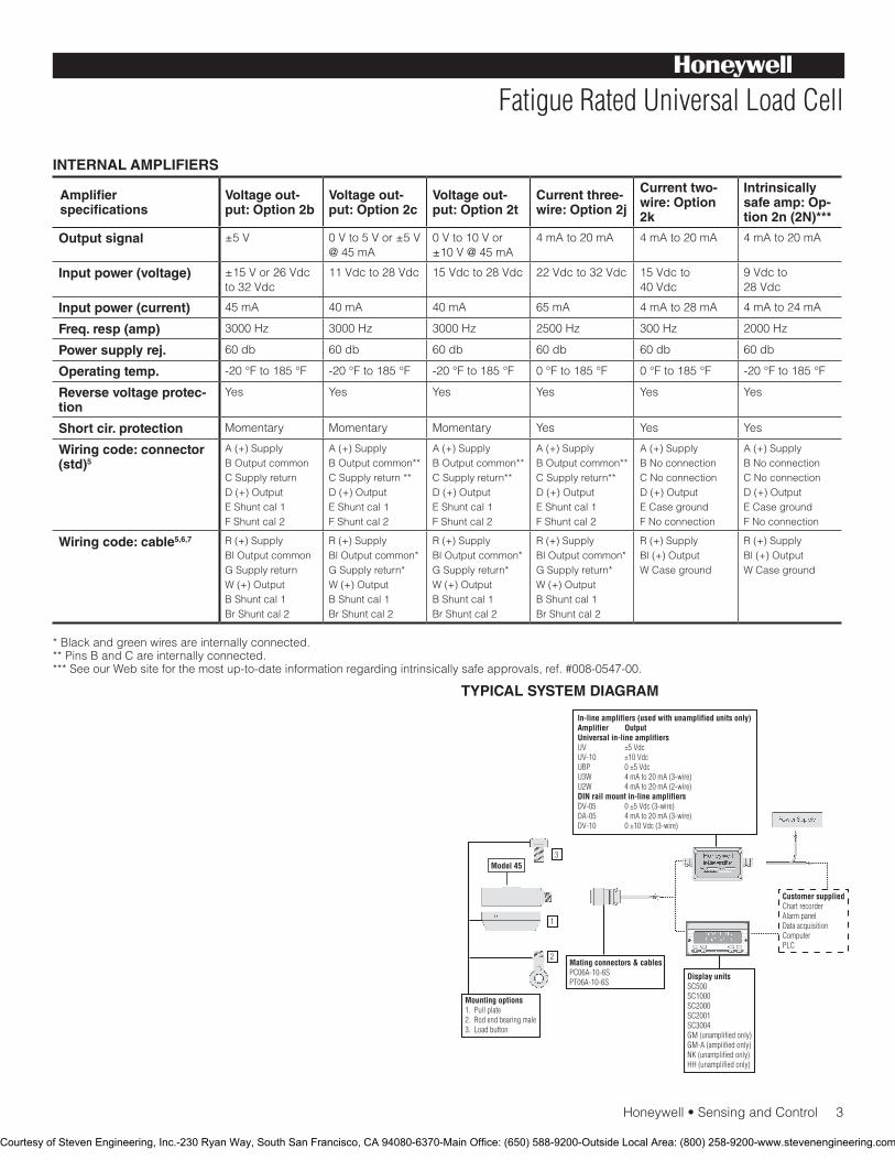
Honeywell•SensingandControl3
Fatigue Rated Universal Load Cell
INTERNAL AMPLIFIERS
Amplifier specifications
Voltage out-put: Option 2b
Voltage out-put: Option 2c
Voltage out-put: Option 2t
Current three-wire: Option 2j
Current two-wire: Option 2k
Intrinsically safe amp: Op-tion 2n (2N)***
Output signal ±5 V 0 V to 5 V or ±5 V @ 45 mA
0 V to 10 V or ±10 V @ 45 mA
4 mA to 20 mA 4 mA to 20 mA 4 mA to 20 mA
Input power (voltage) ±15 V or 26 Vdc to 32 Vdc
11 Vdc to 28 Vdc 15 Vdc to 28 Vdc 22 Vdc to 32 Vdc 15 Vdc to 40 Vdc
9 Vdc to 28 Vdc
Input power (current) 45 mA 40 mA 40 mA 65 mA 4 mA to 28 mA 4 mA to 24 mA
Freq. resp (amp) 3000 Hz 3000 Hz 3000 Hz 2500 Hz 300 Hz 2000 Hz
Power supply rej. 60 db 60 db 60 db 60 db 60 db 60 db
Operating temp. -20 °F to 185 °F -20 °F to 185 °F -20 °F to 185 °F 0 °F to 185 °F 0 °F to 185 °F -20 °F to 185 °F
Reverse voltage protec-tion
Yes Yes Yes Yes Yes Yes
Short cir. protection Momentary Momentary Momentary Yes Yes Yes
Wiring code: connector (std)5
A(+)SupplyB Output commonCSupplyreturnD(+)OutputEShuntcal1FShuntcal2
A(+)SupplyB Output common**CSupplyreturn**D(+)OutputEShuntcal1FShuntcal2
A(+)SupplyB Output common**CSupplyreturn**D(+)OutputEShuntcal1FShuntcal2
A(+)SupplyB Output common**CSupplyreturn**D(+)OutputEShuntcal1FShuntcal2
A(+)SupplyBNoconnectionCNoconnectionD(+)OutputECasegroundFNoconnection
A(+)SupplyBNoconnectionCNoconnectionD(+)OutputECasegroundFNoconnection
Wiring code: cable5,6,7 R(+)SupplyBl Output commonGSupplyreturnW(+)OutputBShuntcal1BrShuntcal2
R(+)SupplyBl Output common*GSupplyreturn*W(+)OutputBShuntcal1BrShuntcal2
R(+)SupplyBl Output common*GSupplyreturn*W(+)OutputBShuntcal1BrShuntcal2
R(+)SupplyBl Output common*GSupplyreturn*W(+)OutputBShuntcal1BrShuntcal2
R(+)SupplyBl(+)OutputW Case ground
R(+)SupplyBl(+)OutputW Case ground
* Black and green wires are internally connected.** Pins B and C are internally connected.***SeeourWebsiteforthemostup-to-dateinformationregardingintrinsicallysafeapprovals,ref.#008-0547-00.
TYPICAL SYSTEM DIAGRAM
Courtesy of Steven Engineering, Inc.-230 Ryan Way, South San Francisco, CA 94080-6370-Main Office: (650) 588-9200-Outside Local Area: (800) 258-9200-www.stevenengineering.com
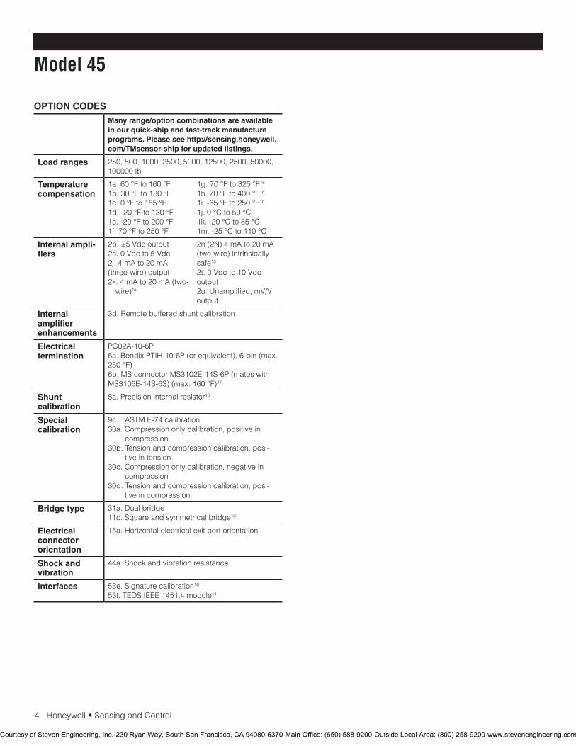
4Honeywell•SensingandControl
Model 45
OPTION CODESMany range/option combinations are available in our quick-ship and fast-track manufacture programs. Please see http://sensing.honeywell.com/TMsensor-ship for updated listings.
Load ranges 250, 500, 1000, 2500, 5000, 12500, 2500, 50000, 100000 lb
Temperature compensation
1a. 60 °F to 160 °F1b. 30 °F to 130 °F1c. 0 °F to 185 °F1d. -20 °F to 130 °F1e. -20 °F to 200 °F 1f. 70 °F to 250 °F
1g. 70 °F to 325 °F16
1h. 70 °F to 400 °F16
1i. -65 °F to 250 °F16
1j. 0 °C to 50 °C1k. -20 °C to 85 °C1m. -25 °C to 110 °C
Internal ampli-fiers
2b. ±5 Vdc output2c. 0 Vdc to 5 Vdc2j. 4 mA to 20 mA (three-wire)output2k.4mAto20mA(two-
wire)15
2n(2N)4mAto20mA(two-wire)intrinsicallysafe15
2t. 0 Vdc to 10 Vdc output2u. Unamplified, mV/V output
Internal amplifier enhancements
3d. Remote buffered shunt calibration
Electrical termination
PC02A-10-6P6a.BendixPTIH-10-6P(orequivalent),6-pin(max.250 °F)6b.MSconnectorMS3102E-14S-6P(mateswithMS3106E-14S-6S)(max.160°F)17
Shunt calibration
8a. Precision internal resistor16
Special calibration
9c. ASTME-74calibration30a. Compression only calibration, positive in
compression30b. Tension and compression calibration, posi-
tive in tension30c. Compression only calibration, negative in
compression30d. Tension and compression calibration, posi-
tive in compression
Bridge type 31a. Dual bridge11c.Squareandsymmetricalbridge16
Electrical connector orientation
15a.Horizontalelectricalexitportorientation
Shock and vibration
44a.Shockandvibrationresistance
Interfaces 53e.Signaturecalibration16
53t.TEDSIEEE1451.4module11
Courtesy of Steven Engineering, Inc.-230 Ryan Way, South San Francisco, CA 94080-6370-Main Office: (650) 588-9200-Outside Local Area: (800) 258-9200-www.stevenengineering.com
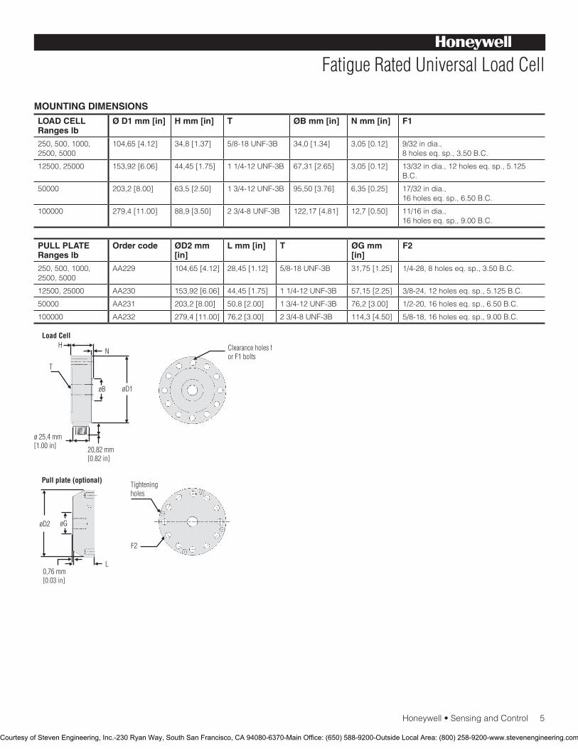
Honeywell•SensingandControl5
Fatigue Rated Universal Load Cell
MOUNTING DIMENSIONS
LOAD CELL Ranges lb
Ø D1 mm [in] H mm [in] T ØB mm [in] N mm [in] F1
250, 500, 1000, 2500, 5000
104,65 [4.12] 34,8 [1.37] 5/8-18UNF-3B 34,0 [1.34] 3,05 [0.12] 9/32 in dia., 8holeseq.sp.,3.50B.C.
12500, 25000 153,92 [6.06] 44,45 [1.75] 11/4-12UNF-3B 67,31 [2.65] 3,05 [0.12] 13/32india.,12holeseq.sp.,5.125B.C.
50000 203,2 [8.00] 63,5 [2.50] 13/4-12UNF-3B 95,50 [3.76] 6,35 [0.25] 17/32 in dia., 16holeseq.sp.,6.50B.C.
100000 279,4 [11.00] 88,9 [3.50] 23/4-8UNF-3B 122,17 [4.81] 12,7 [0.50] 11/16 in dia., 16holeseq.sp.,9.00B.C.
PULL PLATE Ranges lb
Order code ØD2 mm [in]
L mm [in] T ØG mm [in]
F2
250, 500, 1000, 2500, 5000
AA229 104,65 [4.12] 28,45 [1.12] 5/8-18UNF-3B 31,75 [1.25] 1/4-28,8holeseq.sp.,3.50B.C.
12500, 25000 AA230 153,92 [6.06] 44,45 [1.75] 11/4-12UNF-3B 57,15 [2.25] 3/8-24,12holeseq.sp.,5.125B.C.
50000 AA231 203,2 [8.00] 50,8 [2.00] 13/4-12UNF-3B 76,2 [3.00] 1/2-20,16holeseq.sp.,6.50B.C.
100000 AA232 279,4 [11.00] 76,2 [3.00] 23/4-8UNF-3B 114,3 [4.50] 5/8-18,16holeseq.sp.,9.00B.C.
Courtesy of Steven Engineering, Inc.-230 Ryan Way, South San Francisco, CA 94080-6370-Main Office: (650) 588-9200-Outside Local Area: (800) 258-9200-www.stevenengineering.com
SensingandControl
AutomationandControlSolutions
Honeywell
1985DouglasDriveNorth
GoldenValley,MN55422USA
+1-815-235-6847
www.honeywell.com/sensing
008612-1-EN IL50 GLO May 2008Copyright © 2008 Honeywell International Inc. All rights reserved.
Model 45 Fatigue Rated Universal Load Cell
Warranty. Honeywell warrants goods of its manufacture as being free of defective materials and faulty workmanship. Honeywell’s standard product warranty applies unless agreed to otherwise by Honeywell in writing; please refer to your order acknowledgement or consult your local sales office for specificwarrantydetails.IfwarrantedgoodsarereturnedtoHoneywell during the period of coverage, Honeywell will repair or replace, at its option, without charge those items it finds defective. The foregoing is buyer’s sole remedy and is in lieu of all warranties, expressed or implied, including those of merchantability and fitness for a particular purpose. In no event shall Honeywell be liable for consequential, special, or indirect damages.
While we provide application assistance personally, through our literature and the Honeywell web site, it is up to the customer to determine the suitability of the product in the application.
Specificationsmaychangewithoutnotice.Theinformationwesupply is believed to be accurate and reliable as of this printing. However, we assume no responsibility for its use.
FormoreinformationaboutSensingandControlproducts,visitwww.honeywell.com/sensingorcall+1-815-235-6847Emailinquiriestoinfo.sc@honeywell.com
WARNINGPERSONAL INJURY•DONOTUSEtheseproductsassafetyoremergencystopdevicesorinanyotherapplicationwherefailureoftheproductcouldresultinpersonalinjury.
Failure to comply with these instructions could result in death or serious injury.
WARNINGMISUSE OF DOCUMENTATION•Theinformationpresentedinthiscatalogueisforreferenceonly.DONOTUSEthisdocumentasproductinstallationinformation.•Completeinstallation,operationandmaintenanceinformationisprovidedintheinstructionssuppliedwitheachproduct.
Failure to comply with these instructions could result in death or serious injury.
NOTES
1. Staticerrorbandistherecommendedperformancespecifica-tion. The static error band is calculated as the best fit straight line through zero, including the effects of non-linearity, hysteresis and non-repeatability.
2. Values noted are typical values but fall within the static error.3. Allowablemaximumloads–maximumloadtobeappliedwithout
damage.4 4. Withoutdamage-loadingtothislevelwillnotcauseexcessivezero
shift or performance degradation. The user must consider fatigue life for long term use and structural integrity. All structurally critical applications(overheadloading,etc.)shouldalwaysbedesignedwith safety redundant load paths.
5. Interconnectingshuntcal.1terminalwithshuntcal.2terminalprovides50%(unamplifiedunits),75%(4mAto20mAthree-wireunits)or80%(voltageamplifiedunits)offullscaleoutputforquickcalibration.Shuntcalibrationcomesstandardwithinternalamplifieroption 2c, 2t and 2j.
6. O=Orange; Y=Yellow; B=Blue; Bl=Black; R=Red; Br=Brown; W=White; G=Green. Color specifying cable and number or letter specifying connector.
7. Nomatingconnectornecessaryforcableoption.8. 250 lb. range has 700 ohm bridge resistance.9. Offaxisloadingmaximumallowable50%fullscale.10. Internalamplifierforrangeslessthan12,500lbmayincreasein
height.11. ConsultfactoryforTEDSavailabilitywithamplifiedmodels.12. Range dependent; consult factory. Termination dependent; consult
factory.13. Internalampandterminationdependent;consultfactory.14. ThisunitcalibratedtoImperial(non-Metric)units.15. 5000ohmbridgerequired.16. Cannot be used with amplified option.17. Cannot be used with options 1c, 1e, 1f, 1g, 1h, or 1i.
Courtesy of Steven Engineering, Inc.-230 Ryan Way, South San Francisco, CA 94080-6370-Main Office: (650) 588-9200-Outside Local Area: (800) 258-9200-www.stevenengineering.com
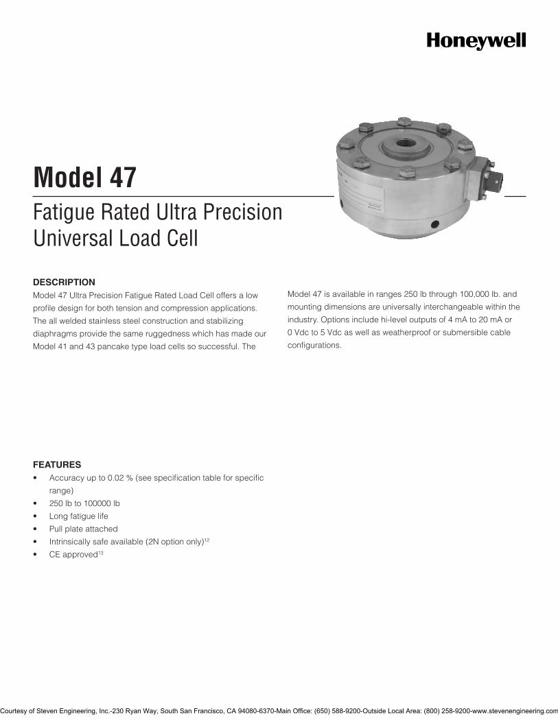
Model 47 is available in ranges 250 lb through 100,000 lb. and
mounting dimensions are universally interchangeable within the
industry. Options include hi-level outputs of 4 mA to 20 mA or
0 Vdc to 5 Vdc as well as weatherproof or submersible cable
configurations.
Fatigue Rated Ultra PrecisionUniversal Load Cell
Model 47
DESCRIPTIONModel 47 Ultra Precision Fatigue Rated Load Cell offers a low
profile design for both tension and compression applications.
The all welded stainless steel construction and stabilizing
diaphragms provide the same ruggedness which has made our
Model 41 and 43 pancake type load cells so successful. The
FEATURES• Accuracy up to 0.02 % (see specification table for specific
range)
• 250 lb to 100000 lb
• Long fatigue life
• Pull plate attached
• Intrinsically safe available (2N option only)12
• CE approved13
Courtesy of Steven Engineering, Inc.-230 Ryan Way, South San Francisco, CA 94080-6370-Main Office: (650) 588-9200-Outside Local Area: (800) 258-9200-www.stevenengineering.com
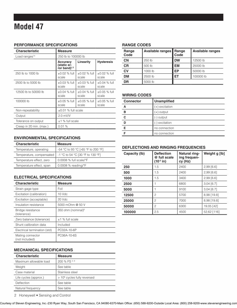
2 Honeywell • Sensing and Control
Model 47
PERFORMANCE SPECIFICATIONS
Characteristic Measure
Load ranges14 250 lb to 100000 lb
Accuracy (static er-ror band)1,2
Linearity Hysteresis
250 lb to 1000 lb ±0.02 % full scale
±0.02 % full scale
±0.02 % full scale
2500 lb to 5000 lb ±0.03 % full scale
±0.03 % full scale
±0.04 % full scale
12500 lb to 50000 lb ±0.04 % full scale
±0.04 % full scale
±0.05 % full scale
100000 lb ±0.05 % full scale
±0.05 % full scale
±0.05 % full scale
Non-repeatability ±0.01 % full scale
Output 2.0 mV/V
Tolerance on output ±1 % full scale
Creep in 20 min. (max.) 0.01 %
ENVIRONMENTAL SPECIFICATIONS
Characteristic Measure
Temperature, operating -54 °C to 93 °C [-65 °F to 200 °F]
Temperature, compensated -1 °C to 54 °C [30 °F to 130 °F]
Temperature effect, zero 0.0008 % full scale/°F
Temperature effect, span 0.0008 % reading/°F
ELECTRICAL SPECIFICATIONS
Characteristic Measure
Strain gage type Foil
Excitation (calibration) 10 Vdc
Excitation (acceptable) 20 Vdc
Insulation resistance 5000 mOhm @ 50 V
Bridge resistance (tolerance)
350 ohm (nominal)8
Zero balance (tolerance) ±1 % full scale
Shunt calibration data Included
Electrical termination (std) PC02A-10-6P
Mating connector (not included)
PC06A-10-6S
MECHANICAL SPECIFICATIONS
Characteristic Measure
Maximum allowable load 200 % FS 3, 9
Weight See table
Case material Stainless steel
Life cycles (approx.) > 108 cycles fully reversed
Deflection See table
Natural frequency See table
RANGE CODES
Range Code
Available ranges Range Code
Available ranges
CN 250 lb DW 12500 lb
CR 500 lb EM 25000 lb
CV 1000 lb EP 50000 lb
DM 2500 lb ET 100000 lb
DR 5000 lb
WIRING CODES
Connector Unamplified
A (+) excitation
B (+) output
C (-) output
D (-) excitation
E no connection
F no connection
DEFLECTIONS AND RINGING FREQUENCIES
Capacity (lb) Deflection @ full scale (10-3 in)
Natural ring-ing frequen-cy (Hz)
Weight g [lb]
250 1.5 2400 2,99 [6.6]
500 1.5 2400 2,99 [6.6]
1000 1.5 3400 2,99 [6.6]
2500 1 6800 3,04 [6.7]
5000 1 9100 3,04 [6.7]
12500 2 5700 8,98 [19.8]
25000 2 7000 8,98 [19.8]
50000 2 6300 19,05 [42]
100000 2.5 4500 52,62 [116]
Courtesy of Steven Engineering, Inc.-230 Ryan Way, South San Francisco, CA 94080-6370-Main Office: (650) 588-9200-Outside Local Area: (800) 258-9200-www.stevenengineering.com

Honeywell • Sensing and Control 3
Fatigue Rated Ultra Precision Universal Load Cell
INTERNAL AMPLIFIERS
Amplifier specifications
Voltage out-put: Option 2b
Voltage out-put: Option 2c
Voltage out-put: Option 2t
Current three-wire: Option 2j
Current two-wire: Option 2k
Intrinsically safe amp: Op-tion 2n (2N)***
Output signal ±5 V 0 V to 5 V or ±5 V @ 45 mA
0 V to 10 V or ±10 V @ 45 mA
4 mA to 20 mA 4 mA to 20 mA 4 mA to 20 mA
Input power (voltage) ±15 V or 26 Vdc to 32 Vdc
11 Vdc to 28 Vdc 15 Vdc to 28 Vdc 22 Vdc to 32 Vdc 15 Vdc to 40 Vdc
9 Vdc to 28 Vdc
Input power (current) 45 mA 40 mA 40 mA 65 mA 4 mA to 28 mA 4 mA to 24 mA
Freq. resp (amp) 3000 Hz 3000 Hz 3000 Hz 2500 Hz 300 Hz 2000 Hz
Power supply rej. 60 db 60 db 60 db 60 db 60 db 60 db
Operating temp. -20 °F to 185 °F -20 °F to 185 °F -20 °F to 185 °F 0 °F to 185 °F 0 °F to 185 °F -20 °F to 185 °F
Reverse voltage protec-tion
Yes Yes Yes Yes Yes Yes
Short cir. protection Momentary Momentary Momentary Yes Yes Yes
Wiring code: connector (std)5
A (+) SupplyB Output commonC Supply returnD (+) OutputE Shunt cal 1F Shunt cal 2
A (+) SupplyB Output common**C Supply return **D (+) OutputE Shunt cal 1F Shunt cal 2
A (+) SupplyB Output common**C Supply return**D (+) OutputE Shunt cal 1F Shunt cal 2
A (+) SupplyB Output common**C Supply return**D (+) OutputE Shunt cal 1F Shunt cal 2
A (+) SupplyB No connectionC No connectionD (+) OutputE Case groundF No connection
A (+) SupplyB No connectionC No connectionD (+) OutputE Case groundF No connection
Wiring code: cable5,6,7 R (+) SupplyBl Output commonG Supply returnW (+) OutputB Shunt cal 1Br Shunt cal 2
R (+) SupplyBl Output common*G Supply return*W (+) OutputB Shunt cal 1Br Shunt cal 2
R (+) SupplyBl Output common*G Supply return*W (+) OutputB Shunt cal 1Br Shunt cal 2
R (+) SupplyBl Output common*G Supply return*W (+) OutputB Shunt cal 1Br Shunt cal 2
R (+) SupplyBl (+) OutputW Case ground
R (+) SupplyBl (+) OutputW Case ground
* Black and green wires are internally connected.** Pins B and C are internally connected.*** See our Web site for the most up-to-date information regarding intrinsically safe approvals, ref. #008-0547-00.
TYPICAL SYSTEM DIAGRAM
Courtesy of Steven Engineering, Inc.-230 Ryan Way, South San Francisco, CA 94080-6370-Main Office: (650) 588-9200-Outside Local Area: (800) 258-9200-www.stevenengineering.com
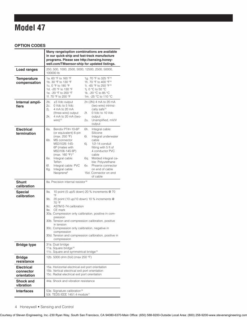
4 Honeywell • Sensing and Control
Model 47
OPTION CODESMany range/option combinations are available in our quick-ship and fast-track manufacture programs. Please see http://sensing.honey-well.com/TMsensor-ship for updated listings.
Load ranges 250, 500, 1000, 2500, 5000, 12500, 2500, 50000, 100000 lb
Temperature compensation
1a. 60 °F to 160 °F1b. 30 °F to 130 °F1c. 0 °F to 185 °F1d. -20 °F to 130 °F1e. -20 °F to 200 °F 1f. 70 °F to 250 °F
1g. 70 °F to 325 °F16
1h. 70 °F to 400 °F16
1i. -65 °F to 250 °F16
1j. 0 °C to 50 °C1k. -20 °C to 85 °C1m. -25 °C to 110 °C
Internal ampli-fiers
2b. ±5 Vdc output2c. 0 Vdc to 5 Vdc2j. 4 mA to 20 mA
(three-wire) output2k. 4 mA to 20 mA (two-
wire)15
2n (2N) 4 mA to 20 mA (two-wire) intrinsi-cally safe15
2t. 0 Vdc to 10 Vdc output
2u. Unamplified, mV/V output
Electrical termination
6a. Bendix PTIH-10-6P (or equivalent) 6-pin (max. 250 °F)
6b. MS connector MS3102E-14S-6P (mates with MS3106-14S 6P) (max. 160 °F)17
6e. Integral cable: Teflon
6f. Integral cable: PVC6g. Integral cable:
Neoprene6
6h. Integral cable: Silicone
6i. Integral underwater cable
6j. 1/2-14 conduit fitting with 5 ft of 4 conductor PVC cable
6q. Molded integral ca-ble: Polyurethane
6v. Phoenix connector on end of cable
15d. Connector on end of cable
Shunt calibration
8a. Precision internal resistor16
Special calibration
9a. 10 point (5 up/5 down) 20 % increments @ 70 °F
9b. 20 point (10 up/10 down) 10 % increments @ 70 °F
9c. ASTM E-74 calibration9e. CE mark30a. Compression only calibration, positive in com-
pression30b. Tension and compression calibration, positive
in tension30c. Compression only calibration, negative in
compression30d. Tension and compression calibration, positive in
compression
Bridge type 31a. Dual bridge11a. Square bridge16
11c. Square and symmetrical bridge16
Bridge resistance
12b. 5000 ohm (foil) (max 250 °F)
Electrical connector orientation
15a. Horizontal electrical exit port orientation15b. Vertical electrical exit port orientation15c. Radial electrical exit port orientation
Shock and vibration
44a. Shock and vibration resistance
Interfaces 53e. Signature calibration16
53t. TEDS IEEE 1451.4 module11
Courtesy of Steven Engineering, Inc.-230 Ryan Way, South San Francisco, CA 94080-6370-Main Office: (650) 588-9200-Outside Local Area: (800) 258-9200-www.stevenengineering.com
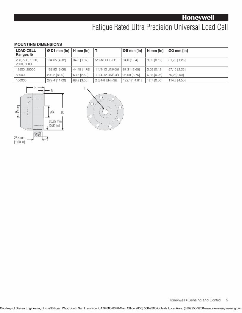
Honeywell • Sensing and Control 5
Fatigue Rated Ultra Precision Universal Load Cell
MOUNTING DIMENSIONS
LOAD CELL Ranges lb
Ø D1 mm [in] H mm [in] T ØB mm [in] N mm [in] ØG mm [in]
250, 500, 1000, 2500, 5000
104,65 [4.12] 34,8 [1.37] 5/8-18 UNF-3B 34,0 [1.34] 3,05 [0.12] 31,75 [1.25]
12500, 25000 153,92 [6.06] 44,45 [1.75] 1 1/4-12 UNF-3B 67,31 [2.65] 3,05 [0.12] 57,15 [2.25]
50000 203,2 [8.00] 63,5 [2.50] 1 3/4-12 UNF-3B 95,50 [3.76] 6,35 [0.25] 76,2 [3.00]
100000 279,4 [11.00] 88,9 [3.50] 2 3/4-8 UNF-3B 122,17 [4.81] 12,7 [0.50] 114,3 [4.50]
Courtesy of Steven Engineering, Inc.-230 Ryan Way, South San Francisco, CA 94080-6370-Main Office: (650) 588-9200-Outside Local Area: (800) 258-9200-www.stevenengineering.com
Sensing and Control
Automation and Control Solutions
Honeywell
1985 Douglas Drive North
Golden Valley, MN 55422 USA
+1-815-235-6847
www.honeywell.com/sensing
008613-1-EN IL50 GLO May 2008Copyright © 2008 Honeywell International Inc. All rights reserved.
Model 47 Fatigue Rated Ultra Precision Universal Load Cell
Warranty. Honeywell warrants goods of its manufacture as being free of defective materials and faulty workmanship. Honeywell’s standard product warranty applies unless agreed to otherwise by Honeywell in writing; please refer to your order acknowledgement or consult your local sales office for specific warranty details. If warranted goods are returned to Honeywell during the period of coverage, Honeywell will repair or replace, at its option, without charge those items it finds defective. The foregoing is buyer’s sole remedy and is in lieu of all warranties, expressed or implied, including those of merchantability and fitness for a particular purpose. In no event shall Honeywell be liable for consequential, special, or indirect damages.
While we provide application assistance personally, through our literature and the Honeywell web site, it is up to the customer to determine the suitability of the product in the application.
Specifications may change without notice. The information we supply is believed to be accurate and reliable as of this printing. However, we assume no responsibility for its use.
For more information about Sensing and Control products, visit www.honeywell.com/sensing or call +1-815-235-6847Email inquiries to [email protected]
WARNINGPERSONAL INJURY•DONOTUSEtheseproductsassafetyoremergencystopdevicesorinanyotherapplicationwherefailureoftheproductcouldresultinpersonalinjury.
Failure to comply with these instructions could result in death or serious injury.
WARNINGMISUSE OF DOCUMENTATION•Theinformationpresentedinthiscatalogueisforreferenceonly.DONOTUSEthisdocumentasproductinstallationinformation.•Completeinstallation,operationandmaintenanceinformationisprovidedintheinstructionssuppliedwitheachproduct.
Failure to comply with these instructions could result in death or serious injury.
NOTES
1. Static error band is the recommended performance specifica-tion. The static error band is calculated as the best fit straight line through zero, including the effects of non-linearity, hysteresis and non-repeatability.
2. Values noted are typical values but fall within the static error.3. Allowable maximum loads – maximum load to be applied without damage.4
4. Without damage - loading to this level will not cause excessive zero shift or performance degradation. The user must consider fatigue life for long term use and structural integrity. All structurally critical applications (overhead loading, etc.) should always be designed with safety redundant load paths.
5. Interconnecting shunt cal. 1 terminal with shunt cal. 2 terminal provides 50 % (unamplified units), 75 % (4 mA to 20 mA three-wire units) or 80 % (voltage amplified units) of full scale output for quick calibration. Shunt calibration comes standard with internal amplifier option 2c, 2t and 2j.
6. O=Orange; Y=Yellow; B=Blue; Bl=Black; R=Red; Br=Brown; W=White; G=Green. Color specifying cable and number or letter specifying connector.
7. No mating connector necessary for cable option.8. 250 lb range has 700 ohm bridge resistance.9. Off axis loading maximum allowable 50% full scale.10. Internal amplifier for ranges less than 12500 lb may increase in
height.11. Consult factory for TEDS availability with amplified models.12. Range dependent; consult factory. Termination dependent; consult
factory.13. Internal amp and termination dependent; consult factory.14. This unit calibrated to Imperial (non-Metric) units.15. 5000 ohm bridge required.16. Cannot be used with amplified option.17. Cannot be used with options 1c, 1e, 1f, 1g, 1h, or 1i.
Courtesy of Steven Engineering, Inc.-230 Ryan Way, South San Francisco, CA 94080-6370-Main Office: (650) 588-9200-Outside Local Area: (800) 258-9200-www.stevenengineering.com

Precision Fatigue-Rated Low Profile Load Cell
Model 73
DESCRIPTIONModel 73 fatigue-rated load cells are engineered for applications
such as materials or product fatigue testing, which involve an
extremely large number of cycles or occasional overload condi-
tions. These fatigue rated load cells have load ranges from 50
lbs to 200,000 lbs and achieve a non-linearity of 0.1% full scale.
The superior design of these bonded foil, strain gage compres-
sion load cells permits a fatigue life of 1 billion cycles (zero to full
scale). Model 73 measures compression only. It must be used
on a smooth flat surface to achieve rated specifications. The
load button on Model 73 is an integral part of the load cell and
cannot be removed or changed. Model 73 utilizes two stabilizing
diaphragms, which are welded to the sensing member to reduce
off-center and side-loading effects.
FEATURES• 0.10%accuracy
• 50lbto200000lb
• mV/Voutput(standard);4mAto20mAor0Vdcto5Vdc
(optional) output
• Stainlesssteel
• Doublediaphragmdesign
• Enhancedoverloadcapacity
• Intrinsicallysafeavailable(2Noptiononly)7
• CEapproved8
Approved Approved ApprovedIntrinsically safe amp
Courtesy of Steven Engineering, Inc.-230 Ryan Way, South San Francisco, CA 94080-6370-Main Office: (650) 588-9200-Outside Local Area: (800) 258-9200-www.stevenengineering.com
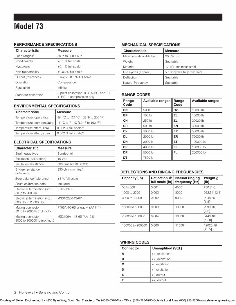
2Honeywell•SensingandControl
Model 73
PERFORMANCE SPECIFICATIONS
Characteristic Measure
Load ranges9 50 lb to 200000 lb
Non-linearity ±0.1 % full scale
Hysteresis ±0.1 % full scale
Non-repeatability ±0.03 % full scale
Output (tolerance) 2mV/V±0.5%fullscale
Operation Compression
Resolution Infinite
Standardcalibration5-point calibration, 0 %, 50 %, and 100 %F.S.incompressiononly
ENVIRONMENTAL SPECIFICATIONS
Characteristic Measure
Temperature, operating -54°Cto121°C[-65°Fto250°F]
Temperature, compensated 15°Cto71°C[60°Fto160°F]
Temperature effect, zero 0.002%fullscale/°F
Temperature effect, span 0.002%fullscale/°F
ELECTRICAL SPECIFICATIONS
Characteristic Measure
Straingagetype Bonded foil
Excitation(calibration) 10Vdc
Insulation resistance 5000mOhm@50Vdc
Bridge resistance (tolerance)
350 ohm (nominal)
Zero balance (tolerance) ±1 % full scale
Shuntcalibrationdata Included
Electricaltermination(std)50 lb to 2000 lb
PTIH-10-6P
Electricaltermination(std)3000 lb to 200000 lb
MS3102E-14S-6P
Mating connector 50 lb to 2000 lb (not incl.)
PT06A-10-6Sorequiv.(AA111)
Mating connector 3000 to 200000 lb (not incl.)
MS3106A-14S-6S(AA121)
MECHANICAL SPECIFICATIONS
Characteristic Measure
Maximum allowable load 200%FS2
Weight Seetable
Material 17-4PHstainlesssteel
Life cycles (approx) > 108 cycles fully reversed
Deflection Seetable
Naturalfrequency Seetable
RANGE CODES
Range Code
Available ranges Range Code
Available ranges
BN 50 lb DV 10000 lb
BR 100 lb EJ 15000 lb
CN 250 lb EL 20000 lb
CR 500 lb EN 30000 lb
CV 1000 lb EP 50000 lb
DL 2000 lb ER 75000 lb
DN 3000 lb ET 100000 lb
DP 4000lb FJ 150000 lb
DR 5000 lb FL 200000 lb
DT 7500 lb
WIRING CODES
Connector Unamplified (Std.)
A (+) excitation
B (+) excitation
C (-) excitation
D (-) excitation
E (-) output
F (+) output
DEFLECTIONS AND RINGING FREQUENCIES
Capacity (lb) Deflection @ full scale (in)
Natural ringing frequency (Hz)
Weight g (lb)
50 to 500 0.001 4500 730[1.6]
1000 to 2000 0.002 8000 952,54[2.1]
3000 to 10000 0.002 9000 2948,35[6.5]
15000 to 50000 0.003 10000 2993,70 [6.6]
75000 to 100000 0.004 13000 5443,10[12.0]
150000 to 200000 0.006 11000 12020,19 [26.5]
Courtesy of Steven Engineering, Inc.-230 Ryan Way, South San Francisco, CA 94080-6370-Main Office: (650) 588-9200-Outside Local Area: (800) 258-9200-www.stevenengineering.com
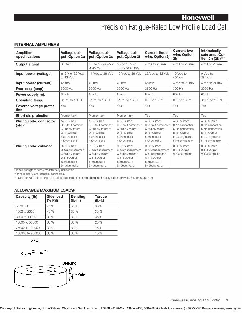
Honeywell•SensingandControl3
Precision Fatigue-Rated Low Profile Load Cell
INTERNAL AMPLIFIERS
Amplifier specifications
Voltage out-put: Option 2a
Voltage out-put: Option 2c
Voltage out-put: Option 2t
Current three-wire: Option 2j
Current two-wire: Option 2k
Intrinsically safe amp: Op-tion 2n (2N)***
Output signal 0Vto5V 0Vto5Vor±5V@45mA
0Vto10Vor±10V@45mA
4mAto20mA 4mAto20mA 4mAto20mA
Input power (voltage) ±15Vor26Vdcto32Vdc
11Vdcto28Vdc 15Vdcto28Vdc 22Vdcto32Vdc 15Vdcto 40Vdc
9Vdcto 28Vdc
Input power (current) 45mA 40mA 40mA 65mA 4mAto28mA 4mAto24mA
Freq. resp (amp) 3000 Hz 3000 Hz 3000 Hz 2500 Hz 300 Hz 2000 Hz
Power supply rej. 60db 60db 60db 60db 60db 60db
Operating temp. -20°Fto185°F -20°Fto185°F -20°Fto185°F 0°Fto185°F 0°Fto185°F -20°Fto185°F
Reverse voltage protec-tion
Yes Yes Yes Yes Yes Yes
Short cir. protection Momentary Momentary Momentary Yes Yes Yes
Wiring code: connector (std)4
A(+)SupplyB Output commonCSupplyreturnD(+)OutputEShuntcal1FShuntcal2
A(+)SupplyB Output common**CSupplyreturn**D(+)OutputEShuntcal1FShuntcal2
A(+)SupplyB Output common**CSupplyreturn**D(+)OutputEShuntcal1FShuntcal2
A(+)SupplyB Output common**CSupplyreturn**D(+)OutputEShuntcal1FShuntcal2
A(+)SupplyBNoconnectionCNoconnectionD(+)OutputECasegroundFNoconnection
A(+)SupplyBNoconnectionCNoconnectionD(+)OutputECasegroundFNoconnection
Wiring code: cable4,5,6 R(+)SupplyBl Output commonGSupplyreturnW (+) OutputBShuntcal1BrShuntcal2
R(+)SupplyBl Output common*GSupplyreturn*W (+) OutputBShuntcal1BrShuntcal2
R(+)SupplyBl Output common*GSupplyreturn*W (+) OutputBShuntcal1BrShuntcal2
R(+)SupplyBl Output common*GSupplyreturn*W (+) OutputBShuntcal1BrShuntcal2
R(+)SupplyBl (+) OutputWCaseground
R(+)SupplyBl (+) OutputWCaseground
* Black and green wires are internally connected.**PinsBandCareinternallyconnected.***SeeourWebsiteforthemostup-to-dateinformationregardingintrinsicallysafeapprovals,ref.#008-0547-00.
ALLOWABLE MAXIMUM LOADS2
Capacity (lb) Side load (% FS)
Bending (lb-in)
Torque (lb-ft)
50 to 500 75 % 60% 35 %
1000 to 2000 45% 35 % 35 %
3000 to 10000 30 % 30 % 35 %
15000 to 50000 30 % 30 % 25 %
75000 to 100000 30 % 30 % 15 %
150000 to 200000 30 % 30 % 15 %
Courtesy of Steven Engineering, Inc.-230 Ryan Way, South San Francisco, CA 94080-6370-Main Office: (650) 588-9200-Outside Local Area: (800) 258-9200-www.stevenengineering.com
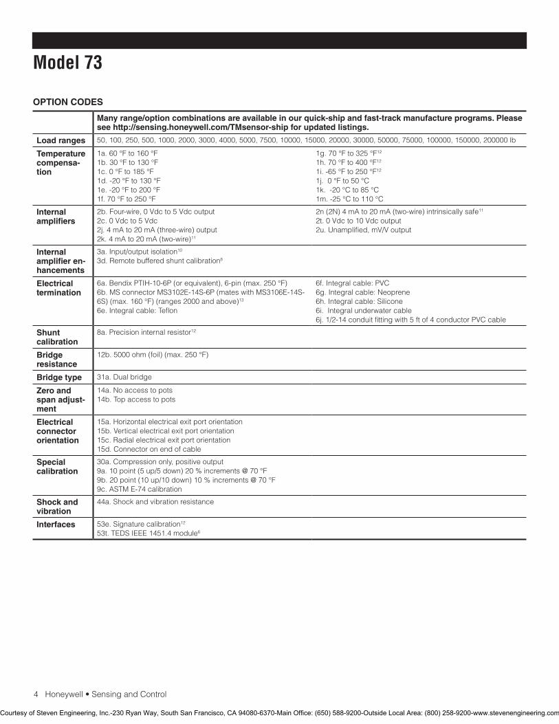
4Honeywell•SensingandControl
Model 73
OPTION CODES
Many range/option combinations are available in our quick-ship and fast-track manufacture programs. Please see http://sensing.honeywell.com/TMsensor-ship for updated listings.
Load ranges 50,100,250,500,1000,2000,3000,4000,5000,7500,10000,15000,20000,30000,50000,75000,100000,150000,200000lb
Temperature compensa-tion
1a.60°Fto160°F1b.30°Fto130°F1c.0°Fto185°F1d.-20°Fto130°F1e.-20°Fto200°F1f.70°Fto250°F
1g.70°Fto325°F12
1h.70°Fto400°F12
1i.-65°Fto250°F12
1j.0°Fto50°C1k.-20°Cto85°C1m.-25°Cto110°C
Internal amplifiers
2b.Four-wire,0Vdcto5Vdcoutput2c.0Vdcto5Vdc2j.4mAto20mA(three-wire)output2k.4mAto20mA(two-wire)11
2n(2N)4mAto20mA(two-wire)intrinsicallysafe11
2t.0Vdcto10Vdcoutput2u.Unamplified,mV/Voutput
Internal amplifier en-hancements
3a.Input/outputisolation10
3d. Remote buffered shunt calibration8
Electrical termination
6a.BendixPTIH-10-6P(orequivalent),6-pin(max.250°F)6b.MSconnectorMS3102E-14S-6P(mateswithMS3106E-14S-6S)(max.160°F)(ranges2000andabove)13
6e.Integralcable:Teflon
6f.Integralcable:PVC6g.Integralcable:Neoprene6h.Integralcable:Silicone6i.Integralunderwatercable6j.1/2-14conduitfittingwith5ftof4conductorPVCcable
Shunt calibration
8a. Precision internal resistor12
Bridge resistance
12b.5000ohm(foil)(max.250°F)
Bridge type 31a.Dualbridge
Zero and span adjust-ment
14a.Noaccesstopots14b.Topaccesstopots
Electrical connector orientation
15a. Horizontal electrical exit port orientation15b.Verticalelectricalexitportorientation15c. Radial electrical exit port orientation15d.Connectoronendofcable
Special calibration
30a.Compressiononly,positiveoutput9a.10point(5up/5down)20%increments@70°F9b.20point(10up/10down)10%increments@70°F9c.ASTME-74calibration
Shock and vibration
44a.Shockandvibrationresistance
Interfaces 53e.Signaturecalibration12
53t.TEDSIEEE1451.4module6
Courtesy of Steven Engineering, Inc.-230 Ryan Way, South San Francisco, CA 94080-6370-Main Office: (650) 588-9200-Outside Local Area: (800) 258-9200-www.stevenengineering.com
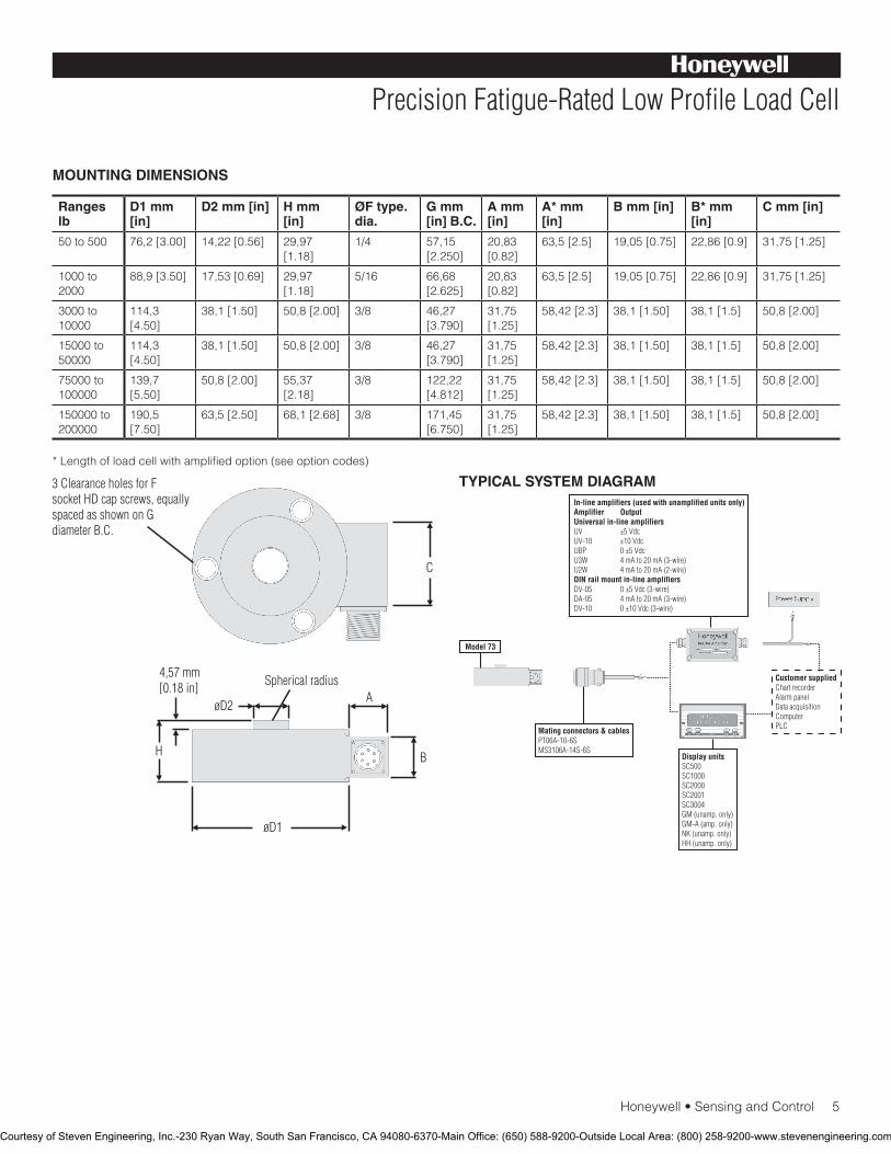
Honeywell•SensingandControl5
Precision Fatigue-Rated Low Profile Load Cell
MOUNTING DIMENSIONS
Ranges lb
D1 mm [in]
D2 mm [in] H mm [in]
ØF type. dia.
G mm [in] B.C.
A mm [in]
A* mm [in]
B mm [in] B* mm [in]
C mm [in]
50 to 500 76,2[3.00] 14,22[0.56] 29,97 [1.18]
1/4 57,15 [2.250]
20,83 [0.82]
63,5[2.5] 19,05[0.75] 22,86[0.9] 31,75[1.25]
1000 to 2000
88,9[3.50] 17,53[0.69] 29,97 [1.18]
5/16 66,68[2.625]
20,83 [0.82]
63,5[2.5] 19,05[0.75] 22,86[0.9] 31,75[1.25]
3000 to 10000
114,3[4.50]
38,1[1.50] 50,8[2.00] 3/8 46,27[3.790]
31,75 [1.25]
58,42[2.3] 38,1[1.50] 38,1[1.5] 50,8[2.00]
15000 to 50000
114,3[4.50]
38,1[1.50] 50,8[2.00] 3/8 46,27[3.790]
31,75 [1.25]
58,42[2.3] 38,1[1.50] 38,1[1.5] 50,8[2.00]
75000 to 100000
139,7 [5.50]
50,8[2.00] 55,37 [2.18]
3/8 122,22 [4.812]
31,75 [1.25]
58,42[2.3] 38,1[1.50] 38,1[1.5] 50,8[2.00]
150000 to 200000
190,5 [7.50]
63,5[2.50] 68,1[2.68] 3/8 171,45[6.750]
31,75 [1.25]
58,42[2.3] 38,1[1.50] 38,1[1.5] 50,8[2.00]
* Length of load cell with amplified option (see option codes)
TYPICAL SYSTEM DIAGRAM
Courtesy of Steven Engineering, Inc.-230 Ryan Way, South San Francisco, CA 94080-6370-Main Office: (650) 588-9200-Outside Local Area: (800) 258-9200-www.stevenengineering.com
SensingandControl
AutomationandControlSolutions
Honeywell
1985DouglasDriveNorth
GoldenValley,MN55422USA
+1-815-235-6847
www.honeywell.com/sensing
008628-1-EN IL50 GLO May 2008Copyright © 2008 Honeywell International Inc. All rights reserved.
Model 73 Precision Fatigue-Rate Low Profile Load Cell
Warranty. Honeywell warrants goods of its manufacture as being free of defective materials and faulty workmanship. Honeywell’s standard product warranty applies unless agreed tootherwisebyHoneywellinwriting;pleaserefertoyourorder acknowledgement or consult your local sales office for specific warranty details. If warranted goods are returned to Honeywell during the period of coverage, Honeywell will repair or replace, at its option, without charge those items it finds defective. The foregoing is buyer’s sole remedy and is in lieu of all warranties, expressed or implied, including those of merchantability and fitness for a particular purpose. In no event shall Honeywell be liable for consequential, special, or indirect damages.
While we provide application assistance personally, through our literature and the Honeywell web site, it is up to the customer to determine the suitability of the product in the application.
Specificationsmaychangewithoutnotice.Theinformationwesupply is believed to be accurate and reliable as of this printing. However, we assume no responsibility for its use.
FormoreinformationaboutSensingandControlproducts,visitwww.honeywell.com/sensingorcall+1-815-235-6847Emailinquiriestoinfo.sc@honeywell.com
WARNINGPERSONAL INJURY•DONOTUSEtheseproductsassafetyoremergencystopdevicesorinanyotherapplicationwherefailureoftheproductcouldresultinpersonalinjury.
Failure to comply with these instructions could result in death or serious injury.
WARNINGMISUSE OF DOCUMENTATION•Theinformationpresentedinthiscatalogueisforreferenceonly.DONOTUSEthisdocumentasproductinstallationinformation.•Completeinstallation,operationandmaintenanceinformationisprovidedintheinstructionssuppliedwitheachproduct.
Failure to comply with these instructions could result in death or serious injury.
NOTES
1. Allowablemaximumloads-maximumloadtobeappliedwithoutdamage.2
2. Without damage - loading to this level will not cause excessive zero shift or performance degradation. The user must consider fatigue lifeforlongtermuseandstructuralintegrity.Allstructurallycriticalapplications (overhead loading, etc.) should always be designed with safety redundant load paths.
3. Interconnecting shunt cal. 1 terminal with shunt cal. 2 terminal provides50%(unamplifiedunits),75%(4mAto20mAthree-wireunits)or80%(voltageamplifiedunits)offullscaleoutputforquickcalibration.Shuntcalibrationcomesstandardwithinternalamplifieroption 2a, 2b, 2c, 2t and 2j.
4. O=Orange;Y=Yellow;B=Blue;Bl=Black; R=Red;Br=Brown;W=White;G=Green.Colorspecifyingcableandnumberorletter
specifying connector. 5. Nomatingconnectornecessaryforcableoption.6. ConsultfactoryforTEDSavailabilitywithamplifiedmodels.7. Rangedependent;consultfactory.Terminationdependent;consult
factory.8. Internalampandterminationdependent;consultfactory.9. This unit calibrated to Imperial (non-Metric) units.10. Input/outputisolationonlyavailablewithvoltageoutput(2bor2c)
amplifier.11. 5000ohmbridgerequired.12. Cannotbeusedwithamplifiedoption.13. Cannotbeusedwithoptions1c,1e,1f,1g,1g,or1i.
Courtesy of Steven Engineering, Inc.-230 Ryan Way, South San Francisco, CA 94080-6370-Main Office: (650) 588-9200-Outside Local Area: (800) 258-9200-www.stevenengineering.com
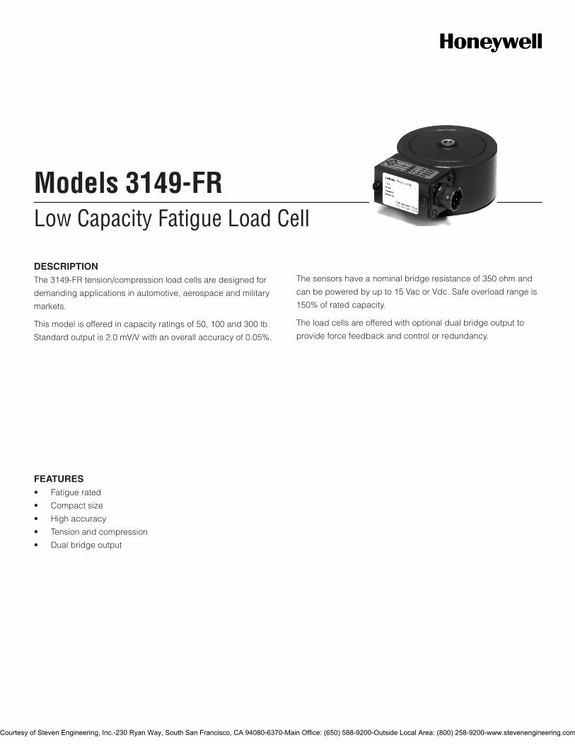
Low Capacity Fatigue Load CellModels 3149-FR
DESCRIPTIONThe 3149-FR tension/compression load cells are designed for
demanding applications in automotive, aerospace and military
markets.
This model is offered in capacity ratings of 50, 100 and 300 lb.
Standard output is 2.0 mV/V with an overall accuracy of 0.05%.
The sensors have a nominal bridge resistance of 350 ohm and
can be powered by up to 15 Vac or Vdc. Safe overload range is
150% of rated capacity.
The load cells are offered with optional dual bridge output to
provide force feedback and control or redundancy.
FEATURES• Fatiguerated
• Compactsize
• Highaccuracy
• Tensionandcompression
• Dualbridgeoutput
Courtesy of Steven Engineering, Inc.-230 Ryan Way, South San Francisco, CA 94080-6370-Main Office: (650) 588-9200-Outside Local Area: (800) 258-9200-www.stevenengineering.com

2Honeywell•SensingandControl
Model 3179-FR
PERFORMANCE SPECIFICATIONS
Characteristic Measure
Load range1 50, 100, 300 lbf
Zero balance ±1.0 % of rated output
Non-linearity ±0.05 % of rated output
Hysteresis ±0.05 % of rated output
Non-repeatability ±0.01 % of rated output
Static error band ±0.05 % of rated output
Creep ±0.03 % (reading in 20 minutes)
ENVIRONMENTAL SPECIFICATIONS
Characteristic Measure
Temperature, operating -54°Cto93°C[-65°Fto200°F]
Temperature, compensated -9°Cto46°C[15°Fto115°F]
Temperature effect, sensitivity
0.08 % reading/100 °F
Temperatureeffect,zero 0.15 % of rated output/100 °F
ELECTRICAL SPECIFICATIONS
Characteristic Measure
Excitation (recommended) 10 Vdc
Input resistance 700 ohm, +40/-3.5 ohm
Output resistance 700 ohm ±3.5 ohm
Sensitivity (rated output) 2 mV/V (nominal)
Insulation resistance, bridge/case
5000 mOhm @ 50 Vdc
MECHANICAL SPECIFICATIONS
Characteristic Measure
Safe overload range 150 % of rated output
Weight 0.8 lb
Flexure material Aluminum
WIRING CODES
Cable
Red (+) excitation
Black (-) excitation
Green (+) output
White (-) output
TYPICAL SYSTEM DIAGRAM
HoneywellIn-Line Amplifier
Output Input
Serial Number
Power Supply
Customer SuppliedChart Recorder
Alarm PanelData Acquisition
ComputerPLC
MODEL 3149FR
(Used with unamplified units only)
UVUV-10UBPU3WU2W
DV-05DA-05DV10
In-Line Amplifiers
AmplifierUniversal In-Line Amplifiers
DIN rail Mount In-Line Amplifiers
Output
+/-5 VDC+/-10 VDC0 +/-5 VDC4-20mA (3 wire)4-20mA (2 wire)
0 +/- 5 VDC (3 wire)4-20mA (3 wire)0 +/- 10 VDC (3 wire)
2003.1 lb.L1 L2 L3 L4
UP DOWN
VALUE CLEAR CHAN TARE
ENTERSETUP EXIT
023-LW181-023-LF Mating Connector7205-76-XX* Mating connector & 6 conductor cable (unamplified unit with sense leads but not shunt cal)7205-75-XX** Mating connector & 4 conductor cable (unamplified unit without sense leads but not shunt cal)7205-83-XX* Mating connector & 6 conductor cable (for connection to instrument 7541)7205-82-XX** Mating connector & 4 conductor cable (for connection to instrument 7541)
* XX represents length in feet 100ft maximum** XX represents length in feet 20ft maximum
Mating Connectors & Cables
SC500 SC1000 SC2000SC2001 SC3004GM NK HH7541 7558 7561-PSD
Display Units
OR
A
2.36
0.03, 2 PLACES1.50
1/4-28 UNF, 0.28 DEEP, 2 PLACES[FOR METRIC VERSION: m6 X 1.0, 7.1 DEEP, 2 PLACES]
Ø0.692 PLACES
2.56 R
OPTIONAL DUAL BRIDGE
Ø2.75
MOUNTING DIMENSIONS
Courtesy of Steven Engineering, Inc.-230 Ryan Way, South San Francisco, CA 94080-6370-Main Office: (650) 588-9200-Outside Local Area: (800) 258-9200-www.stevenengineering.com
SensingandControl
AutomationandControlSolutions
Honeywell
1985DouglasDriveNorth
Golden Valley, MN 55422 USA
+1-815-235-6847
www.honeywell.com/sensing
008620-1-EN IL50 GLO May 2008Copyright © 2008 Honeywell International Inc. All rights reserved.
Model 3179-FR Low Capacity Fatigue Load Cell
NOTES
1. This unit calibrated to Imperial (non-Metric) units.
Warranty. Honeywellwarrantsgoodsofitsmanufactureasbeing free of defective materials and faulty workmanship. Honeywell’sstandardproductwarrantyappliesunlessagreedtootherwisebyHoneywellinwriting;pleaserefertoyourorder acknowledgement or consult your local sales office for specific warranty details. If warranted goods are returned to Honeywellduringtheperiodofcoverage,Honeywellwillrepairor replace, at its option, without charge those items it finds defective. The foregoing is buyer’s sole remedy and is in lieu of all warranties, expressed or implied, including those of merchantability and fitness for a particular purpose. In no event shall Honeywell be liable for consequential, special, or indirect damages.
While we provide application assistance personally, through our literatureandtheHoneywellwebsite,itisuptothecustomertodetermine the suitability of the product in the application.
Specifications may change without notice. The information we supply is believed to be accurate and reliable as of this printing. However,weassumenoresponsibilityforitsuse.
FormoreinformationaboutSensingandControlproducts,visitwww.honeywell.com/sensingorcall+1-815-235-6847Email inquiries to [email protected]
WARNINGPERSONAL INJURY•DONOTUSEtheseproductsassafetyoremergencystopdevicesorinanyotherapplicationwherefailureoftheproductcouldresultinpersonalinjury.
Failure to comply with these instructions could result in death or serious injury.
WARNINGMISUSE OF DOCUMENTATION•Theinformationpresentedinthiscatalogueisforreferenceonly.DONOTUSEthisdocumentasproductinstallationinformation.•Completeinstallation,operationandmaintenanceinformationisprovidedintheinstructionssuppliedwitheachproduct.
Failure to comply with these instructions could result in death or serious injury.
Courtesy of Steven Engineering, Inc.-230 Ryan Way, South San Francisco, CA 94080-6370-Main Office: (650) 588-9200-Outside Local Area: (800) 258-9200-www.stevenengineering.com

Tension/Compression Pancake Load CellModel 3108
DESCRIPTIONThese general purpose designs have exceptional structural
capability to withstand extraneous loads, such as torque,
bending moments, and side loads. This low-range cell has built-
in temperature compensation.
Available in capacities of five and ten pounds, they offer
maximum performance and enhanced accuracy.
Minimum deflection and compactness make these general-
purpose load cells easy to install and use.
FEATURES• 5lbto10lbrange
• 0.05%accuracy
• Lowsensitivitytoextraneousloads
• Lowdeflection
Courtesy of Steven Engineering, Inc.-230 Ryan Way, South San Francisco, CA 94080-6370-Main Office: (650) 588-9200-Outside Local Area: (800) 258-9200-www.stevenengineering.com

2Honeywell•SensingandControl
Model 3108
PERFORMANCE SPECIFICATIONS
Characteristic Measure
Loadrange1 5,10lb
Non-linearity ±0.01%ofratedoutput
Hysteresis ±0.01%ofratedoutput
Repeatability ±0.05%ofratedoutput
Output @ rated capacity 2mV/V±0.25%(nominal)
Operation Tension/compression
Resolution Infinite
Standardcalibration Tension(+)andcompression(-)
ENVIRONMENTAL SPECIFICATIONS
Characteristic Measure
Temperature, operating -54°Cto93°C[-65°Fto200°F]
Temperature, compensated 21°Cto77°C[70°Fto170°F]
Temperature effect, zero ±0.002%ofratedoutput/°F
Temperature effect, output ±0.002%ofreading/°F
ELECTRICAL SPECIFICATIONS
Characteristic Measure
Straingagetype Foil
Excitation(maximum) 20VdcorVacRMS
Insulation resistance >5000mOhm@50Vdc
Bridge resistance (tolerance)
350ohm
Number of bridges 1or2
Zero balance ±1.0%
Electrical termination PT02E-10-6PmateswithPT06W-10-6S
MECHANICAL SPECIFICATIONS
Characteristic Measure
Staticoverloadcapacity 150%ofnominalcapacity
Material Carbonsteel
Natural frequency Seetable
WIRING CODES
Cable
Red (+)excitation
Black (-)excitation
Green (+)output
White (-)output
TYPICAL SYSTEM DIAGRAM
HoneywellIn-Line Amplifier
Output InputSerial Number
Power Supply
Customer SuppliedChart Recorder
Alarm PanelData Acquisition
ComputerPLC
MODEL 3108
(Used with unamplified units only)
UVUV-10UBPU3WU2W
DV-05DA-05DV10
In-Line Amplifiers
Amplifier Universal In-Line Amplifiers
DIN rail Mount In-Line Amplifiers
Output
+/-5 VDC+/-10 VDC0 +/-5 VDC4-20mA (3 wire)4-20mA (2 wire)
0 +/- 5 VDC (3 wire)4-20mA (3 wire)0 +/- 10 VDC (3 wire)
2003.1 lb.L1 L2 L3 L4
UP DOWN
VALUE CLEAR CHAN TARE
ENTERSETUP EXIT
SC500 SC1000 SC2000 SC2001 SC3004 GM NK HH7541 7558 7561-PSD
Display Units
023-LW181-023-LF Mating Connector7205-76-XX* Mating connector & 6 conductor cable (unamplified unit with sense leads but not shunt cal)7205-75-XX** Mating connector & 4 conductor cable (unamplified unit without sense leads but not shunt cal)7205-83-XX* Mating connector & 6 conductor cable (for connection to instrument 7541)7205-82-XX** Mating connector & 4 conductor cable (for connection to instrument 7541)
* XX represents length in feet 100ft maximum** XX represents length in feet 20ft maximum
Mating Connectors & Cables
OR
Courtesy of Steven Engineering, Inc.-230 Ryan Way, South San Francisco, CA 94080-6370-Main Office: (650) 588-9200-Outside Local Area: (800) 258-9200-www.stevenengineering.com
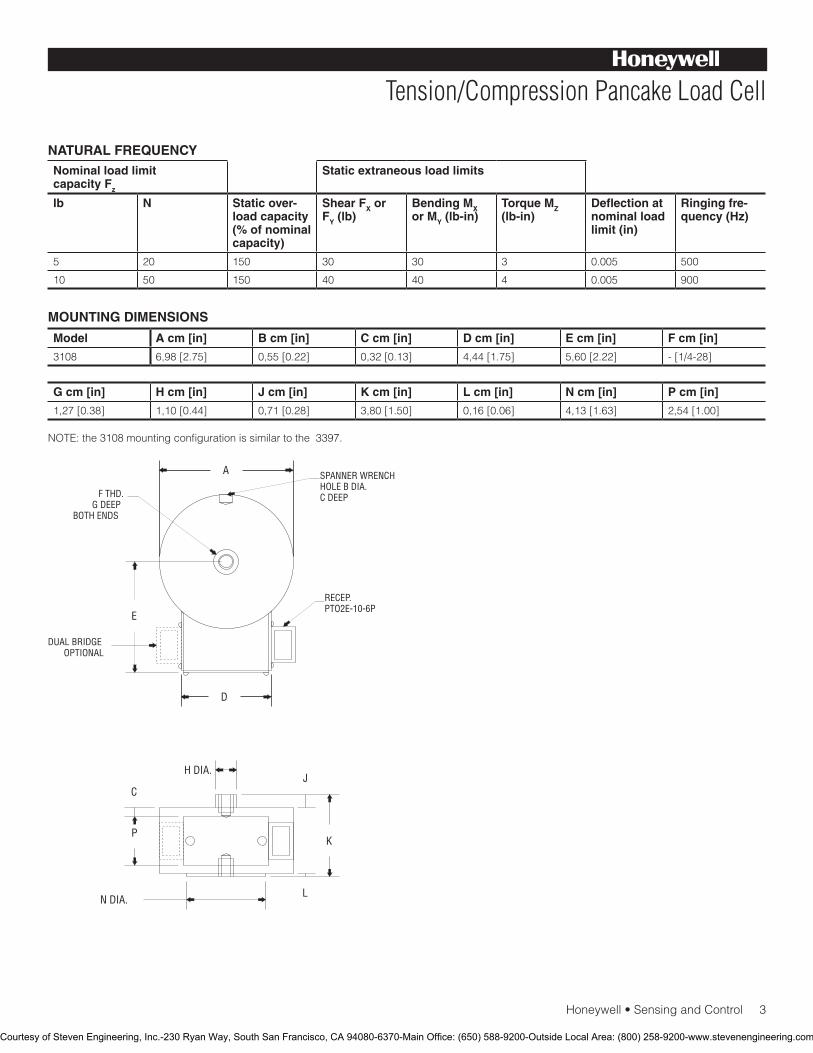
Honeywell•SensingandControl3
Tension/Compression Pancake Load Cell
NATURAL FREQUENCYNominal load limit capacity Fz
Static extraneous load limits
lb N Static over-load capacity (% of nominal capacity)
Shear FX or FY (lb)
Bending MX or MY (lb-in)
Torque MZ (lb-in)
Deflection at nominal load limit (in)
Ringing fre-quency (Hz)
5 20 150 30 30 3 0.005 500
10 50 150 40 40 4 0.005 900
Model A cm [in] B cm [in] C cm [in] D cm [in] E cm [in] F cm [in]
3108 6,98[2.75] 0,55[0.22] 0,32[0.13] 4,44[1.75] 5,60[2.22] -[1/4-28]
G cm [in] H cm [in] J cm [in] K cm [in] L cm [in] N cm [in] P cm [in]
1,27[0.38] 1,10[0.44] 0,71[0.28] 3,80[1.50] 0,16[0.06] 4,13[1.63] 2,54[1.00]
NOTE:the3108mountingconfigurationissimilartothe3397.
A
D
H DIA.
N DIA.
P
CJ
K
L
E
SPANNER WRENCHHOLE B DIA.C DEEPF THD.
G DEEPBOTH ENDS
RECEP.PTO2E-10-6P
DUAL BRIDGEOPTIONAL
MOUNTING DIMENSIONS
Courtesy of Steven Engineering, Inc.-230 Ryan Way, South San Francisco, CA 94080-6370-Main Office: (650) 588-9200-Outside Local Area: (800) 258-9200-www.stevenengineering.com

SensingandControl
AutomationandControlSolutions
Honeywell
1985DouglasDriveNorth
GoldenValley,MN55422USA
+1-815-235-6847
www.honeywell.com/sensing
008621-1-EN IL50 GLO May 2008Copyright © 2008 Honeywell International Inc. All rights reserved.
Model 3108 Tension/Compression Pancake Load Cell
NOTES
1.ThisunitcalibratedtoImperial(non-Metric)units.
Warranty. Honeywell warrants goods of its manufacture as being free of defective materials and faulty workmanship. Honeywell’s standard product warranty applies unless agreed to otherwise by Honeywell in writing; please refer to your order acknowledgement or consult your local sales office for specific warranty details. If warranted goods are returned to Honeywell during the period of coverage, Honeywell will repair or replace, at its option, without charge those items it finds defective. The foregoing is buyer’s sole remedy and is in lieu of all warranties, expressed or implied, including those of merchantability and fitness for a particular purpose. In no event shall Honeywell be liable for consequential, special, or indirect damages.
Whileweprovideapplicationassistancepersonally,throughourliterature and the Honeywell web site, it is up to the customer to determine the suitability of the product in the application.
Specificationsmaychangewithoutnotice.Theinformationwesupply is believed to be accurate and reliable as of this printing. However, we assume no responsibility for its use.
FormoreinformationaboutSensingandControlproducts,visitwww.honeywell.com/sensingorcall+1-815-235-6847Email inquiries to [email protected]
WARNINGPERSONAL INJURY•DONOTUSEtheseproductsassafetyoremergencystopdevicesorinanyotherapplicationwherefailureoftheproductcouldresultinpersonalinjury.
Failure to comply with these instructions could result in death or serious injury.
WARNINGMISUSE OF DOCUMENTATION•Theinformationpresentedinthiscatalogueisforreferenceonly.DONOTUSEthisdocumentasproductinstallationinformation.•Completeinstallation,operationandmaintenanceinformationisprovidedintheinstructionssuppliedwitheachproduct.
Failure to comply with these instructions could result in death or serious injury.
Courtesy of Steven Engineering, Inc.-230 Ryan Way, South San Francisco, CA 94080-6370-Main Office: (650) 588-9200-Outside Local Area: (800) 258-9200-www.stevenengineering.com
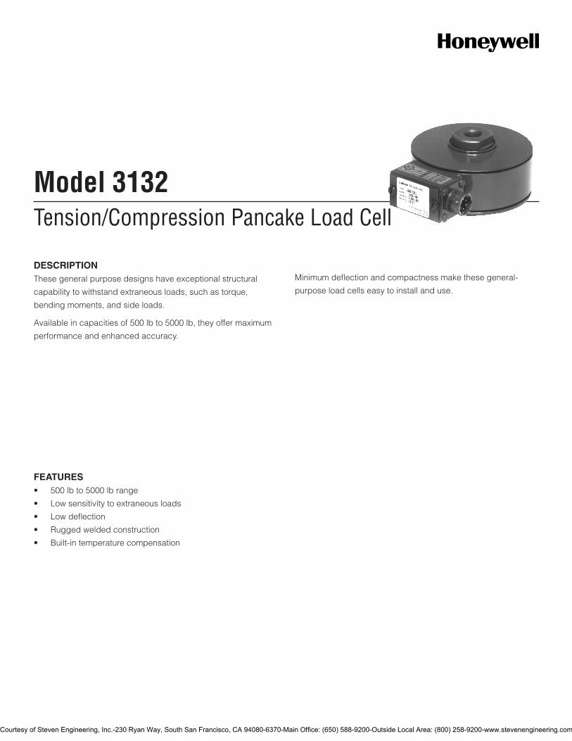
Tension/Compression Pancake Load CellModel 3132
DESCRIPTIONThese general purpose designs have exceptional structural
capability to withstand extraneous loads, such as torque,
bending moments, and side loads.
Available in capacities of 500 lb to 5000 lb, they offer maximum
performance and enhanced accuracy.
Minimum deflection and compactness make these general-
purpose load cells easy to install and use.
FEATURES• 500lbto5000lbrange
• Lowsensitivitytoextraneousloads
• Lowdeflection
• Ruggedweldedconstruction
• Built-intemperaturecompensation
Courtesy of Steven Engineering, Inc.-230 Ryan Way, South San Francisco, CA 94080-6370-Main Office: (650) 588-9200-Outside Local Area: (800) 258-9200-www.stevenengineering.com
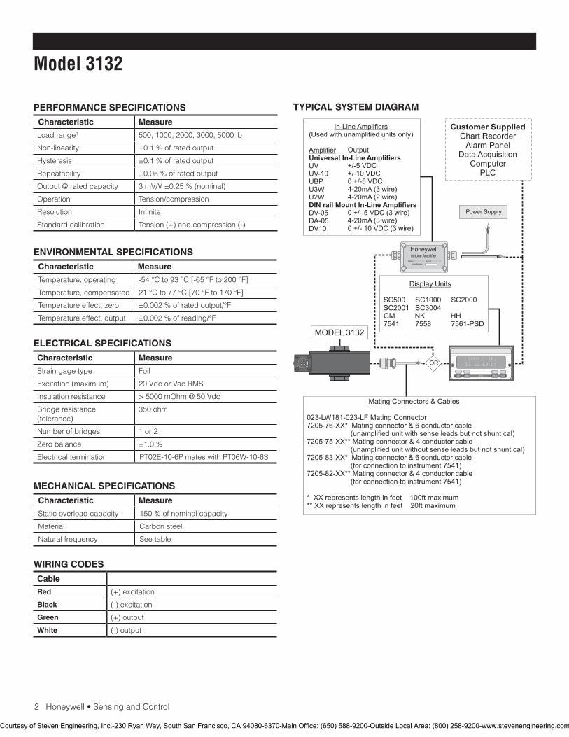
2Honeywell•SensingandControl
Model 3132
PERFORMANCE SPECIFICATIONS
Characteristic Measure
Loadrange1 500, 1000, 2000, 3000, 5000 lb
Non-linearity ±0.1 % of rated output
Hysteresis ±0.1 % of rated output
Repeatability ±0.05 % of rated output
Output @ rated capacity 3 mV/V ±0.25 % (nominal)
Operation Tension/compression
Resolution Infinite
Standardcalibration Tension (+) and compression (-)
ENVIRONMENTAL SPECIFICATIONS
Characteristic Measure
Temperature, operating -54°Cto93°C[-65°Fto200°F]
Temperature, compensated 21°Cto77°C[70°Fto170°F]
Temperature effect, zero ±0.002%ofratedoutput/°F
Temperature effect, output ±0.002%ofreading/°F
ELECTRICAL SPECIFICATIONS
Characteristic Measure
Straingagetype Foil
Excitation (maximum) 20VdcorVacRMS
Insulation resistance > 5000 mOhm @ 50 Vdc
Bridgeresistance(tolerance)
350 ohm
Number of bridges 1 or 2
Zero balance ±1.0 %
Electrical termination PT02E-10-6PmateswithPT06W-10-6S
MECHANICAL SPECIFICATIONS
Characteristic Measure
Staticoverloadcapacity 150 % of nominal capacity
Material Carbonsteel
Natural frequency Seetable
WIRING CODES
Cable
Red (+) excitation
Black (-) excitation
Green (+) output
White (-) output
TYPICAL SYSTEM DIAGRAM
HoneywellIn-Line Amplifier
Output InputSerial Number
Power Supply
Customer SuppliedChart Recorder
Alarm PanelData Acquisition
ComputerPLC
MODEL 3132
(Used with unamplified units only)
UVUV-10UBPU3WU2W
DV-05DA-05DV10
In-Line Amplifiers
Amplifier Universal In-Line Amplifiers
DIN rail Mount In-Line Amplifiers
Output
+/-5 VDC+/-10 VDC0 +/-5 VDC4-20mA (3 wire)4-20mA (2 wire)
0 +/- 5 VDC (3 wire)4-20mA (3 wire)0 +/- 10 VDC (3 wire)
2003.1 lb.L1 L2 L3 L4
UP DOWN
VALUE CLEAR CHAN TARE
ENTERSETUP EXIT
SC500 SC1000 SC2000 SC2001 SC3004 GM NK HH7541 7558 7561-PSD
Display Units
023-LW181-023-LF Mating Connector7205-76-XX* Mating connector & 6 conductor cable (unamplified unit with sense leads but not shunt cal)7205-75-XX** Mating connector & 4 conductor cable (unamplified unit without sense leads but not shunt cal)7205-83-XX* Mating connector & 6 conductor cable (for connection to instrument 7541)7205-82-XX** Mating connector & 4 conductor cable (for connection to instrument 7541)
* XX represents length in feet 100ft maximum** XX represents length in feet 20ft maximum
Mating Connectors & Cables
OR
Courtesy of Steven Engineering, Inc.-230 Ryan Way, South San Francisco, CA 94080-6370-Main Office: (650) 588-9200-Outside Local Area: (800) 258-9200-www.stevenengineering.com
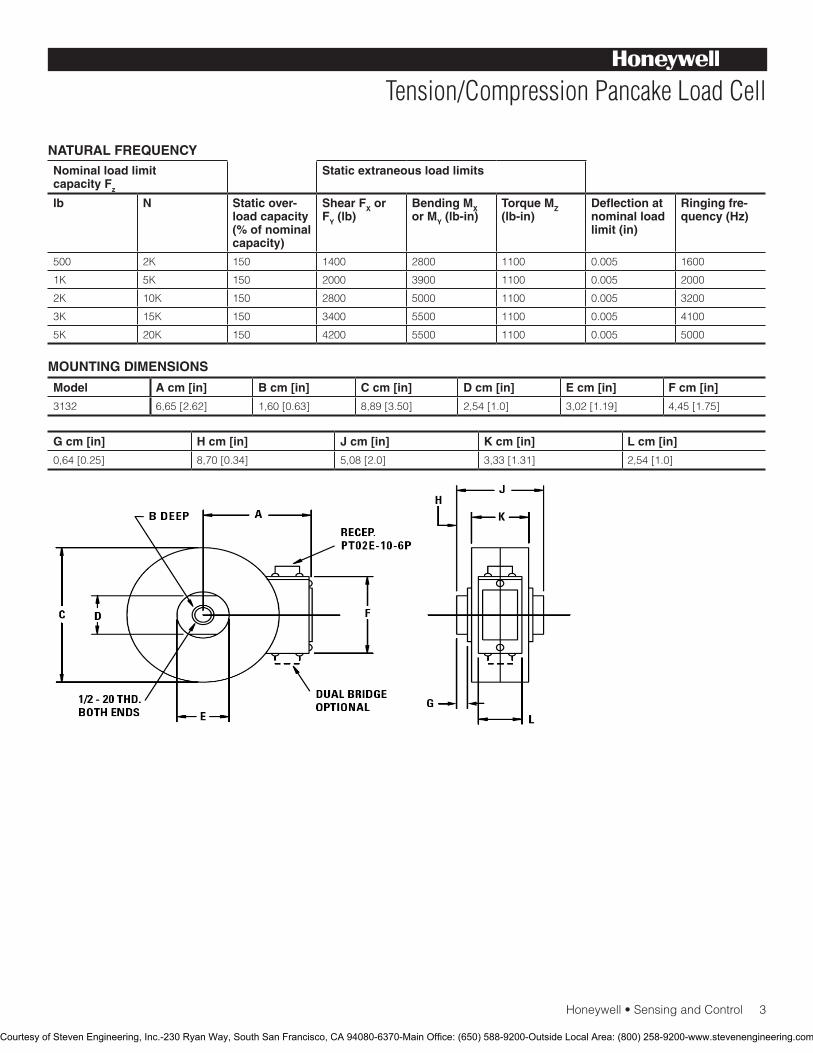
Honeywell•SensingandControl3
Tension/Compression Pancake Load Cell
NATURAL FREQUENCYNominal load limit capacity Fz
Static extraneous load limits
lb N Static over-load capacity (% of nominal capacity)
Shear FX or FY (lb)
Bending MX or MY (lb-in)
Torque MZ (lb-in)
Deflection at nominal load limit (in)
Ringing fre-quency (Hz)
500 2K 150 1400 2800 1100 0.005 1600
1K 5K 150 2000 3900 1100 0.005 2000
2K 10K 150 2800 5000 1100 0.005 3200
3K 15K 150 3400 5500 1100 0.005 4100
5K 20K 150 4200 5500 1100 0.005 5000
Model A cm [in] B cm [in] C cm [in] D cm [in] E cm [in] F cm [in]
3132 6,65[2.62] 1,60[0.63] 8,89[3.50] 2,54[1.0] 3,02[1.19] 4,45[1.75]
G cm [in] H cm [in] J cm [in] K cm [in] L cm [in]
0,64[0.25] 8,70[0.34] 5,08[2.0] 3,33[1.31] 2,54[1.0]
MOUNTING DIMENSIONS
Courtesy of Steven Engineering, Inc.-230 Ryan Way, South San Francisco, CA 94080-6370-Main Office: (650) 588-9200-Outside Local Area: (800) 258-9200-www.stevenengineering.com

SensingandControl
AutomationandControlSolutions
Honeywell
1985DouglasDriveNorth
GoldenValley,MN55422USA
+1-815-235-6847
www.honeywell.com/sensing
008624-1-EN IL50 GLO May 2008Copyright © 2008 Honeywell International Inc. All rights reserved.
Model 3132 Tension/Compression Pancake Load Cell
NOTES
1. This unit calibrated to Imperial (non-Metric) units.
Warranty. Honeywell warrants goods of its manufacture as being free of defective materials and faulty workmanship. Honeywell’s standard product warranty applies unless agreed to otherwise by Honeywell in writing; please refer to your order acknowledgement or consult your local sales office for specific warranty details. If warranted goods are returned to Honeywell during the period of coverage, Honeywell will repair or replace, at its option, without charge those items it finds defective. The foregoing is buyer’s sole remedy and is in lieu of all warranties, expressed or implied, including those of merchantability and fitness for a particular purpose. In no event shall Honeywell be liable for consequential, special, or indirect damages.
Whileweprovideapplicationassistancepersonally,throughourliterature and the Honeywell web site, it is up to the customer to determine the suitability of the product in the application.
Specificationsmaychangewithoutnotice.Theinformationwesupply is believed to be accurate and reliable as of this printing. However, we assume no responsibility for its use.
FormoreinformationaboutSensingandControlproducts,visitwww.honeywell.com/sensingorcall+1-815-235-6847Email inquiries to [email protected]
WARNINGPERSONAL INJURY•DONOTUSEtheseproductsassafetyoremergencystopdevicesorinanyotherapplicationwherefailureoftheproductcouldresultinpersonalinjury.
Failure to comply with these instructions could result in death or serious injury.
WARNINGMISUSE OF DOCUMENTATION•Theinformationpresentedinthiscatalogueisforreferenceonly.DONOTUSEthisdocumentasproductinstallationinformation.•Completeinstallation,operationandmaintenanceinformationisprovidedintheinstructionssuppliedwitheachproduct.
Failure to comply with these instructions could result in death or serious injury.
Courtesy of Steven Engineering, Inc.-230 Ryan Way, South San Francisco, CA 94080-6370-Main Office: (650) 588-9200-Outside Local Area: (800) 258-9200-www.stevenengineering.com
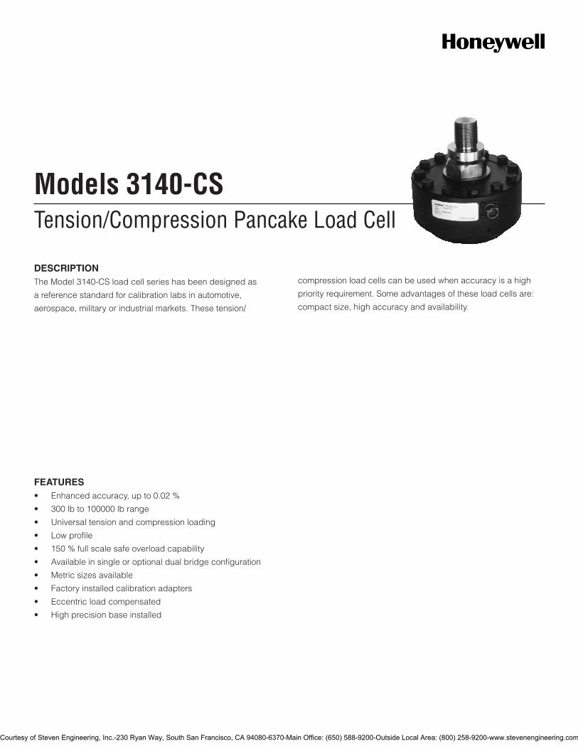
Tension/Compression Pancake Load CellModels 3140-CS
DESCRIPTIONThe Model 3140-CS load cell series has been designed as
a reference standard for calibration labs in automotive,
aerospace, military or industrial markets. These tension/
compression load cells can be used when accuracy is a high
priority requirement. Some advantages of these load cells are:
compact size, high accuracy and availability.
FEATURES• Enhancedaccuracy,upto0.02%
• 300lbto100000lbrange
• Universaltensionandcompressionloading
• Lowprofile
• 150%fullscalesafeoverloadcapability
• Availableinsingleoroptionaldualbridgeconfiguration
• Metricsizesavailable
• Factoryinstalledcalibrationadapters
• Eccentricloadcompensated
• Highprecisionbaseinstalled
Courtesy of Steven Engineering, Inc.-230 Ryan Way, South San Francisco, CA 94080-6370-Main Office: (650) 588-9200-Outside Local Area: (800) 258-9200-www.stevenengineering.com
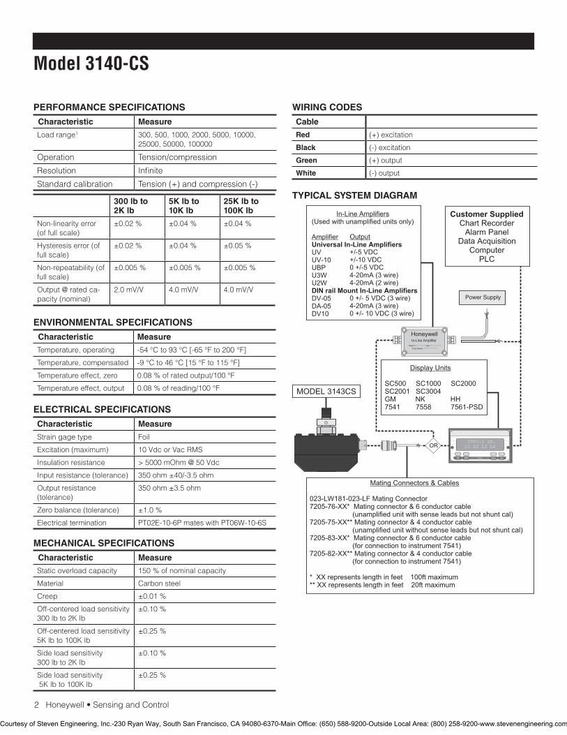
2Honeywell•SensingandControl
Model 3140-CS
PERFORMANCE SPECIFICATIONS
Characteristic Measure
Loadrange1 300,500,1000,2000,5000,10000,25000,50000,100000
Operation Tension/compression
Resolution Infinite
Standard calibration Tension (+) and compression (-)
ENVIRONMENTAL SPECIFICATIONS
Characteristic Measure
Temperature, operating -54°Cto93°C[-65°Fto200°F]
Temperature, compensated -9°Cto46°C[15°Fto115°F]
Temperature effect, zero 0.08%ofratedoutput/100°F
Temperature effect, output 0.08%ofreading/100°F
ELECTRICAL SPECIFICATIONS
Characteristic Measure
Strain gage type Foil
Excitation(maximum) 10 Vdc or Vac RMS
Insulation resistance >5000mOhm@50Vdc
Input resistance (tolerance) 350ohm±40/-3.5ohm
Output resistance (tolerance)
350ohm±3.5ohm
Zero balance (tolerance) ±1.0%
Electricaltermination PT02E-10-6PmateswithPT06W-10-6S
MECHANICAL SPECIFICATIONS
Characteristic Measure
Static overload capacity 150%ofnominalcapacity
Material Carbon steel
Creep ±0.01%
Off-centered load sensitivity 300lbto2Klb
±0.10%
Off-centered load sensitivity 5Klbto100Klb
±0.25%
Side load sensitivity 300lbto2Klb
±0.10%
Side load sensitivity5Klbto100Klb
±0.25%
WIRING CODES
Cable
Red (+)excitation
Black (-)excitation
Green (+) output
White (-) output
TYPICAL SYSTEM DIAGRAM300 lb to 2K lb
5K lb to 10K lb
25K lb to 100K lb
Non-linearity error (of full scale)
±0.02% ±0.04% ±0.04%
Hysteresiserror(offull scale)
±0.02% ±0.04% ±0.05%
Non-repeatability (of full scale)
±0.005% ±0.005% ±0.005%
Output@ratedca-pacity (nominal)
2.0mV/V 4.0 mV/V 4.0 mV/V
HoneywellIn-Line Amplifier
Output InputSerial Number
Power Supply
Customer SuppliedChart Recorder
Alarm PanelData Acquisition
ComputerPLC
MODEL 3143CS
(Used with unamplified units only)
UVUV-10UBPU3WU2W
DV-05DA-05DV10
In-Line Amplifiers
Amplifier Universal In-Line Amplifiers
DIN rail Mount In-Line Amplifiers
Output
+/-5 VDC+/-10 VDC0 +/-5 VDC4-20mA (3 wire)4-20mA (2 wire)
0 +/- 5 VDC (3 wire)4-20mA (3 wire)0 +/- 10 VDC (3 wire)
2003.1 lb.L1 L2 L3 L4
UP DOWN
VALUE CLEAR CHAN TARE
ENTERSETUP EXIT
SC500 SC1000 SC2000 SC2001 SC3004 GM NK HH7541 7558 7561-PSD
Display Units
023-LW181-023-LF Mating Connector7205-76-XX* Mating connector & 6 conductor cable (unamplified unit with sense leads but not shunt cal)7205-75-XX** Mating connector & 4 conductor cable (unamplified unit without sense leads but not shunt cal)7205-83-XX* Mating connector & 6 conductor cable (for connection to instrument 7541)7205-82-XX** Mating connector & 4 conductor cable (for connection to instrument 7541)
* XX represents length in feet 100ft maximum** XX represents length in feet 20ft maximum
Mating Connectors & Cables
OR
Courtesy of Steven Engineering, Inc.-230 Ryan Way, South San Francisco, CA 94080-6370-Main Office: (650) 588-9200-Outside Local Area: (800) 258-9200-www.stevenengineering.com
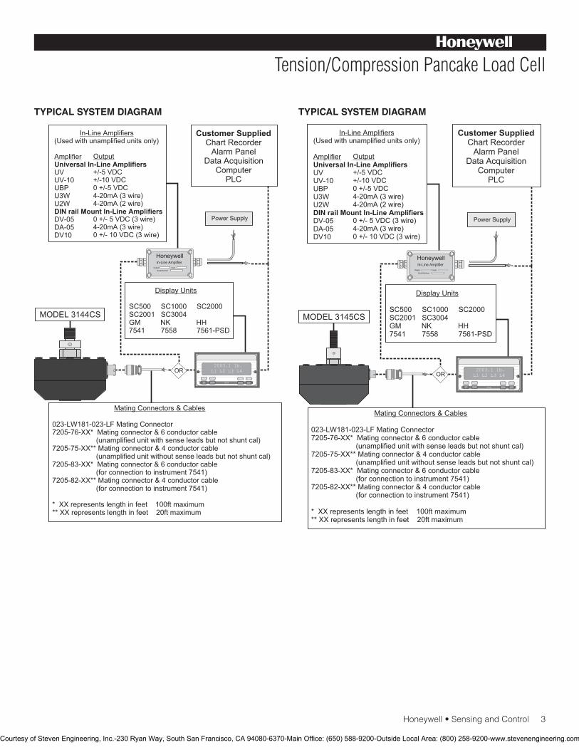
Honeywell•SensingandControl3
Tension/Compression Pancake Load Cell
TYPICAL SYSTEM DIAGRAM TYPICAL SYSTEM DIAGRAM
HoneywellIn-Line Amplifier
Output InputSerial Number
Power Supply
Customer SuppliedChart Recorder
Alarm PanelData Acquisition
ComputerPLC
MODEL 3144CS
(Used with unamplified units only)
UVUV-10UBPU3WU2W
DV-05DA-05DV10
In-Line Amplifiers
Amplifier Universal In-Line Amplifiers
DIN rail Mount In-Line Amplifiers
Output
+/-5 VDC+/-10 VDC0 +/-5 VDC4-20mA (3 wire)4-20mA (2 wire)
0 +/- 5 VDC (3 wire)4-20mA (3 wire)0 +/- 10 VDC (3 wire)
2003.1 lb.L1 L2 L3 L4
UP DOWN
VALUE CLEAR CHAN TARE
ENTERSETUP EXIT
023-LW181-023-LF Mating Connector7205-76-XX* Mating connector & 6 conductor cable (unamplified unit with sense leads but not shunt cal)7205-75-XX** Mating connector & 4 conductor cable (unamplified unit without sense leads but not shunt cal)7205-83-XX* Mating connector & 6 conductor cable (for connection to instrument 7541)7205-82-XX** Mating connector & 4 conductor cable (for connection to instrument 7541)
* XX represents length in feet 100ft maximum** XX represents length in feet 20ft maximum
Mating Connectors & Cables
SC500 SC1000 SC2000 SC2001 SC3004 GM NK HH7541 7558 7561-PSD
Display Units
OR
HoneywellIn-Line Amplifier
Output InputSerial Number
Power Supply
Customer SuppliedChart Recorder
Alarm PanelData Acquisition
ComputerPLC
MODEL 3145CS
(Used with unamplified units only)
UVUV-10UBPU3WU2W
DV-05DA-05DV10
In-Line Amplifiers
Amplifier Universal In-Line Amplifiers
DIN rail Mount In-Line Amplifiers
Output
+/-5 VDC+/-10 VDC0 +/-5 VDC4-20mA (3 wire)4-20mA (2 wire)
0 +/- 5 VDC (3 wire)4-20mA (3 wire)0 +/- 10 VDC (3 wire)
2003.1 lb.L1 L2 L3 L4
UP DOWN
VALUE CLEAR CHAN TARE
ENTERSETUP EXIT
023-LW181-023-LF Mating Connector7205-76-XX* Mating connector & 6 conductor cable (unamplified unit with sense leads but not shunt cal)7205-75-XX** Mating connector & 4 conductor cable (unamplified unit without sense leads but not shunt cal)7205-83-XX* Mating connector & 6 conductor cable (for connection to instrument 7541)7205-82-XX** Mating connector & 4 conductor cable (for connection to instrument 7541)
* XX represents length in feet 100ft maximum** XX represents length in feet 20ft maximum
Mating Connectors & Cables
SC500 SC1000 SC2000 SC2001 SC3004 GM NK HH7541 7558 7561-PSD
Display Units
OR
Courtesy of Steven Engineering, Inc.-230 Ryan Way, South San Francisco, CA 94080-6370-Main Office: (650) 588-9200-Outside Local Area: (800) 258-9200-www.stevenengineering.com
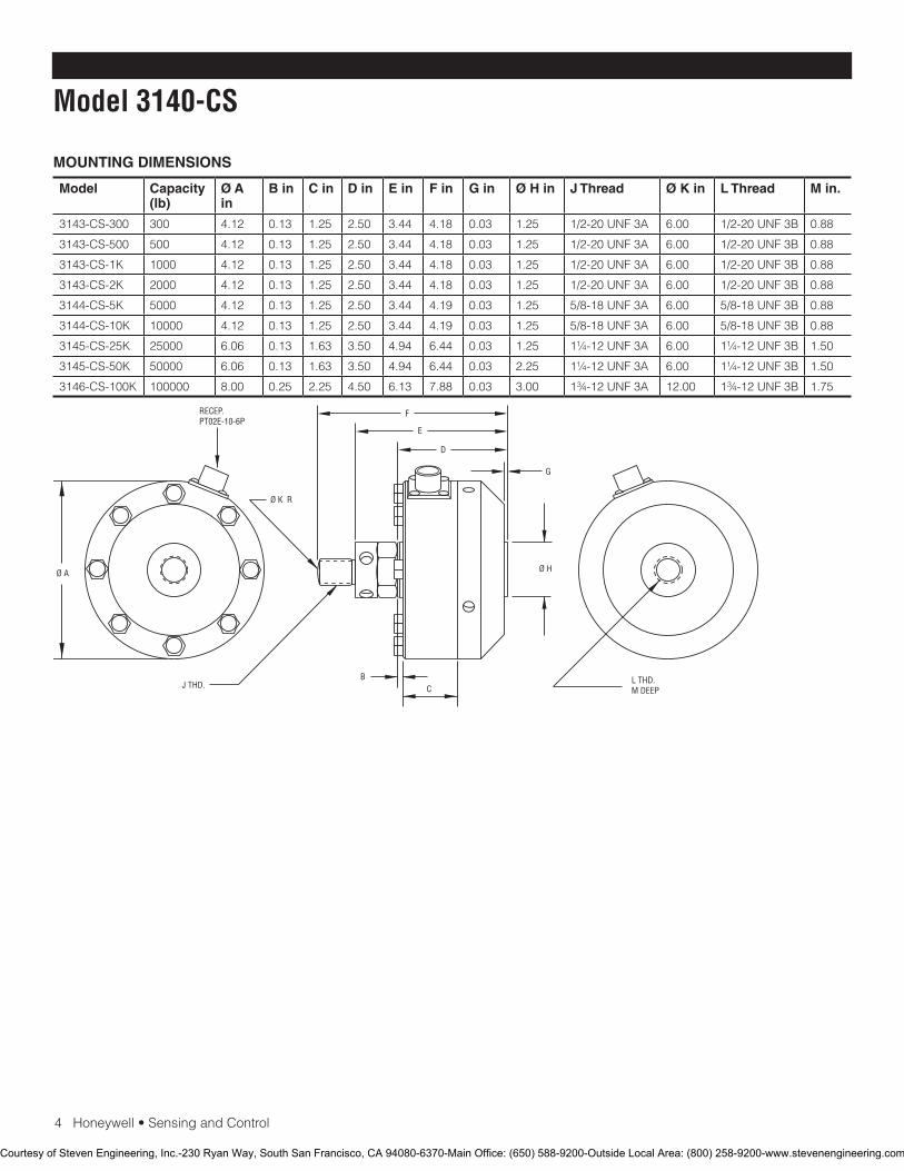
4Honeywell•SensingandControl
Model 3140-CS
MOUNTING DIMENSIONS
Model Capacity (lb)
Ø A in
B in C in D in E in F in G in Ø H in J Thread Ø K in L Thread M in.
3143-CS-300 300 4.12 0.13 1.25 2.50 3.44 4.18 0.03 1.25 1/2-20UNF3A 6.00 1/2-20UNF3B 0.88
3143-CS-500 500 4.12 0.13 1.25 2.50 3.44 4.18 0.03 1.25 1/2-20UNF3A 6.00 1/2-20UNF3B 0.88
3143-CS-1K 1000 4.12 0.13 1.25 2.50 3.44 4.18 0.03 1.25 1/2-20UNF3A 6.00 1/2-20UNF3B 0.88
3143-CS-2K 2000 4.12 0.13 1.25 2.50 3.44 4.18 0.03 1.25 1/2-20UNF3A 6.00 1/2-20UNF3B 0.88
3144-CS-5K 5000 4.12 0.13 1.25 2.50 3.44 4.19 0.03 1.25 5/8-18UNF3A 6.00 5/8-18UNF3B 0.88
3144-CS-10K 10000 4.12 0.13 1.25 2.50 3.44 4.19 0.03 1.25 5/8-18UNF3A 6.00 5/8-18UNF3B 0.88
3145-CS-25K 25000 6.06 0.13 1.63 3.50 4.94 6.44 0.03 1.25 1¼-12UNF3A 6.00 1¼-12UNF3B 1.50
3145-CS-50K 50000 6.06 0.13 1.63 3.50 4.94 6.44 0.03 2.25 1¼-12UNF3A 6.00 1¼-12UNF3B 1.50
3146-CS-100K 100000 8.00 0.25 2.25 4.50 6.13 7.88 0.03 3.00 1¾-12UNF3A 12.00 1¾-12UNF3B 1.75
Ø K R
Ø A
BC
D
E
F
G
Ø H
J THD. L THD.M DEEP
RECEP.PT02E-10-6P
Courtesy of Steven Engineering, Inc.-230 Ryan Way, South San Francisco, CA 94080-6370-Main Office: (650) 588-9200-Outside Local Area: (800) 258-9200-www.stevenengineering.com
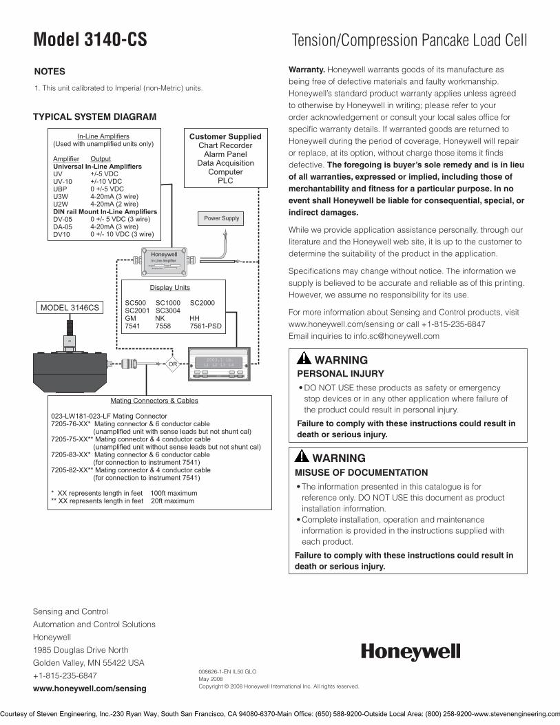
Sensing and Control
AutomationandControlSolutions
Honeywell
1985DouglasDriveNorth
GoldenValley,MN55422USA
+1-815-235-6847
www.honeywell.com/sensing
008626-1-EN IL50 GLO May 2008Copyright © 2008 Honeywell International Inc. All rights reserved.
Model 3140-CS Tension/Compression Pancake Load Cell
NOTES
1. This unit calibrated to Imperial (non-Metric) units.
Warranty. Honeywellwarrantsgoodsofitsmanufactureasbeing free of defective materials and faulty workmanship. Honeywell’sstandardproductwarrantyappliesunlessagreedtootherwisebyHoneywellinwriting;pleaserefertoyourorderacknowledgementorconsultyourlocalsalesofficeforspecificwarrantydetails.IfwarrantedgoodsarereturnedtoHoneywellduringtheperiodofcoverage,Honeywellwillrepairorreplace,atitsoption,withoutchargethoseitemsitfindsdefective. The foregoing is buyer’s sole remedy and is in lieu of all warranties, expressed or implied, including those of merchantability and fitness for a particular purpose. In no event shall Honeywell be liable for consequential, special, or indirect damages.
Whileweprovideapplicationassistancepersonally,throughourliteratureandtheHoneywellwebsite,itisuptothecustomertodetermine the suitability of the product in the application.
Specificationsmaychangewithoutnotice.Theinformationwesupply is believed to be accurate and reliable as of this printing. However,weassumenoresponsibilityforitsuse.
FormoreinformationaboutSensingandControlproducts,visitwww.honeywell.com/sensingorcall+1-815-235-6847Emailinquiriestoinfo.sc@honeywell.com
WARNINGPERSONAL INJURY•DONOTUSEtheseproductsassafetyoremergencystopdevicesorinanyotherapplicationwherefailureoftheproductcouldresultinpersonalinjury.
Failure to comply with these instructions could result in death or serious injury.
WARNINGMISUSE OF DOCUMENTATION•Theinformationpresentedinthiscatalogueisforreferenceonly.DONOTUSEthisdocumentasproductinstallationinformation.•Completeinstallation,operationandmaintenanceinformationisprovidedintheinstructionssuppliedwitheachproduct.
Failure to comply with these instructions could result in death or serious injury.
TYPICAL SYSTEM DIAGRAM
HoneywellIn-Line Amplifier
Output InputSerial Number
Power Supply
Customer SuppliedChart Recorder
Alarm PanelData Acquisition
ComputerPLC
MODEL 3146CS
(Used with unamplified units only)
UVUV-10UBPU3WU2W
DV-05DA-05DV10
In-Line Amplifiers
Amplifier Universal In-Line Amplifiers
DIN rail Mount In-Line Amplifiers
Output
+/-5 VDC+/-10 VDC0 +/-5 VDC4-20mA (3 wire)4-20mA (2 wire)
0 +/- 5 VDC (3 wire)4-20mA (3 wire)0 +/- 10 VDC (3 wire)
2003.1 lb.L1 L2 L3 L4
UP DOWN
VALUE CLEAR CHAN TARE
ENTERSETUP EXIT
023-LW181-023-LF Mating Connector7205-76-XX* Mating connector & 6 conductor cable (unamplified unit with sense leads but not shunt cal)7205-75-XX** Mating connector & 4 conductor cable (unamplified unit without sense leads but not shunt cal)7205-83-XX* Mating connector & 6 conductor cable (for connection to instrument 7541)7205-82-XX** Mating connector & 4 conductor cable (for connection to instrument 7541)
* XX represents length in feet 100ft maximum** XX represents length in feet 20ft maximum
Mating Connectors & Cables
SC500 SC1000 SC2000 SC2001 SC3004 GM NK HH7541 7558 7561-PSD
Display Units
OR
Courtesy of Steven Engineering, Inc.-230 Ryan Way, South San Francisco, CA 94080-6370-Main Office: (650) 588-9200-Outside Local Area: (800) 258-9200-www.stevenengineering.com
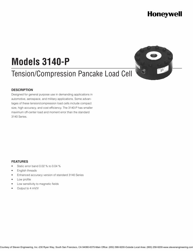
Tension/Compression Pancake Load CellModels 3140-P
DESCRIPTIONDesigned for general purpose use in demanding applications in
automotive, aerospace, and military applications. Some advan-
tages of these tension/compression load cells include compact
size, high accuracy, and cost efficiency. The 3140-P has smaller
maximum off-center load and moment error than the standard
3140 Series.
FEATURES• Staticerrorband0.02%to0.04%
• Englishthreads
• Enhancedaccuracyversionofstandard3140Series
• Lowprofile
• Lowsensitivitytomagneticfields
• Outputto4mV/V
Courtesy of Steven Engineering, Inc.-230 Ryan Way, South San Francisco, CA 94080-6370-Main Office: (650) 588-9200-Outside Local Area: (800) 258-9200-www.stevenengineering.com
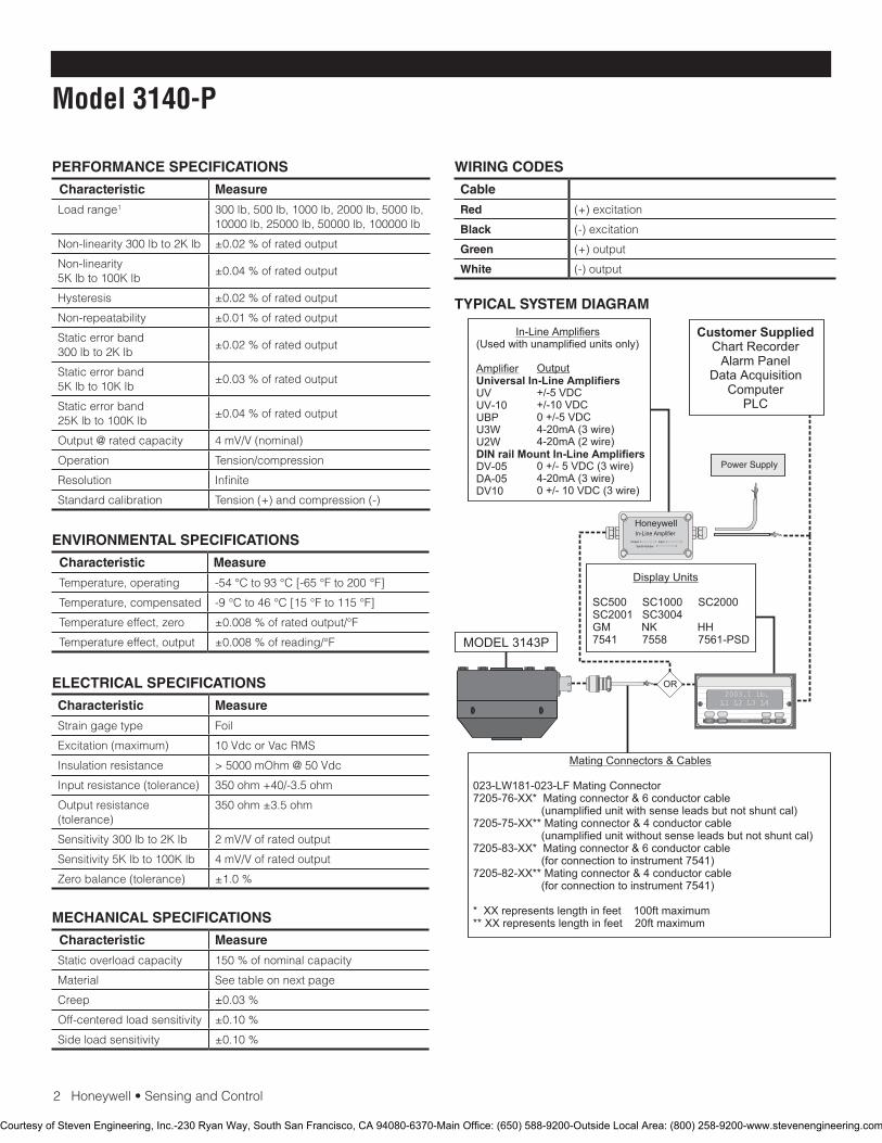
2Honeywell•SensingandControl
Model 3140-P
PERFORMANCE SPECIFICATIONS
Characteristic Measure
Loadrange1 300lb,500lb,1000lb,2000lb,5000lb,10000lb,25000lb,50000lb,100000lb
Non-linearity300lbto2Klb ±0.02%ofratedoutput
Non-linearity 5Klbto100Klb
±0.04%ofratedoutput
Hysteresis ±0.02%ofratedoutput
Non-repeatability ±0.01%ofratedoutput
Staticerrorband300lbto2Klb
±0.02%ofratedoutput
Staticerrorband5Klbto10Klb
±0.03%ofratedoutput
Staticerrorband25Klbto100Klb
±0.04%ofratedoutput
Output@ratedcapacity 4mV/V(nominal)
Operation Tension/compression
Resolution Infinite
Standardcalibration Tension(+)andcompression(-)
ENVIRONMENTAL SPECIFICATIONS
Characteristic Measure
Temperature, operating -54°Cto93°C[-65°Fto200°F]
Temperature, compensated -9°Cto46°C[15°Fto115°F]
Temperature effect, zero ±0.008%ofratedoutput/°F
Temperature effect, output ±0.008%ofreading/°F
ELECTRICAL SPECIFICATIONS
Characteristic Measure
Strain gage type Foil
Excitation(maximum) 10VdcorVacRMS
Insulation resistance >5000mOhm@50Vdc
Inputresistance(tolerance) 350ohm+40/-3.5ohm
Outputresistance(tolerance)
350ohm±3.5ohm
Sensitivity300lbto2Klb 2mV/Vofratedoutput
Sensitivity5Klbto100Klb 4mV/Vofratedoutput
Zerobalance(tolerance) ±1.0%
MECHANICAL SPECIFICATIONS
Characteristic Measure
Static overload capacity 150%ofnominalcapacity
Material Seetableonnextpage
Creep ±0.03%
Off-centeredloadsensitivity ±0.10%
Side load sensitivity ±0.10%
WIRING CODES
Cable
Red (+)excitation
Black (-)excitation
Green (+)output
White (-)output
TYPICAL SYSTEM DIAGRAM
HoneywellIn-Line Amplifier
Output InputSerial Number
Power Supply
Customer SuppliedChart Recorder
Alarm PanelData Acquisition
ComputerPLC
MODEL 3143P
(Used with unamplified units only)
UVUV-10UBPU3WU2W
DV-05DA-05DV10
In-Line Amplifiers
Amplifier Universal In-Line Amplifiers
DIN rail Mount In-Line Amplifiers
Output
+/-5 VDC+/-10 VDC0 +/-5 VDC4-20mA (3 wire)4-20mA (2 wire)
0 +/- 5 VDC (3 wire)4-20mA (3 wire)0 +/- 10 VDC (3 wire)
2003.1 lb.L1 L2 L3 L4
UP DOWN
VALUE CLEAR CHAN TARE
ENTERSETUP EXIT
SC500 SC1000 SC2000 SC2001 SC3004 GM NK HH7541 7558 7561-PSD
Display Units
023-LW181-023-LF Mating Connector7205-76-XX* Mating connector & 6 conductor cable (unamplified unit with sense leads but not shunt cal)7205-75-XX** Mating connector & 4 conductor cable (unamplified unit without sense leads but not shunt cal)7205-83-XX* Mating connector & 6 conductor cable (for connection to instrument 7541)7205-82-XX** Mating connector & 4 conductor cable (for connection to instrument 7541)
* XX represents length in feet 100ft maximum** XX represents length in feet 20ft maximum
Mating Connectors & Cables
OR
Courtesy of Steven Engineering, Inc.-230 Ryan Way, South San Francisco, CA 94080-6370-Main Office: (650) 588-9200-Outside Local Area: (800) 258-9200-www.stevenengineering.com
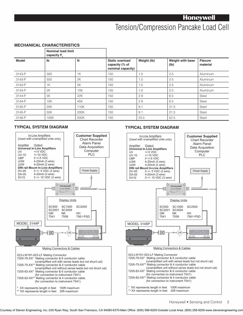
Honeywell•SensingandControl3
Tension/Compression Pancake Load Cell
TYPICAL SYSTEM DIAGRAM TYPICAL SYSTEM DIAGRAM
MECHANICAL CHARACTERISTICSNominal load limit capacity Fz
Model lb N Static overload capacity (% of nominal capacity)
Weight (lb) Weight with base (lb)
Flexure material
3143-P 300 1K 150 1.0 2.5 Aluminum
3143-P 500 2K 150 1.0 2.5 Aluminum
3143-P 1K 5K 150 1.0 2.5 Aluminum
3143-P 2K 10K 150 1.0 2.5 Aluminum
3144-P 5K 22K 150 2.9 6.5 Steel
3144-P 10K 45K 150 2.9 6.5 Steel
3145-P 25K 110K 150 9.1 21.5 Steel
3145-P 50K 200K 150 9.1 21.5 Steel
3146-P 100K 500K 150 23.5 52.5 Steel
HoneywellIn-Line Amplifier
Output InputSerial Number
Power Supply
Customer SuppliedChart Recorder
Alarm PanelData Acquisition
ComputerPLC
MODEL 3144P
(Used with unamplified units only)
UVUV-10UBPU3WU2W
DV-05DA-05DV10
In-Line Amplifiers
Amplifier Universal In-Line Amplifiers
DIN rail Mount In-Line Amplifiers
Output
+/-5 VDC+/-10 VDC0 +/-5 VDC4-20mA (3 wire)4-20mA (2 wire)
0 +/- 5 VDC (3 wire)4-20mA (3 wire)0 +/- 10 VDC (3 wire)
2003.1 lb.L1 L2 L3 L4
UP DOWN
VALUE CLEAR CHAN TARE
ENTERSETUP EXIT
SC500 SC1000 SC2000 SC2001 SC3004 GM NK HH7541 7558 7561-PSD
Display Units
023-LW181-023-LF Mating Connector7205-76-XX* Mating connector & 6 conductor cable (unamplified unit with sense leads but not shunt cal)7205-75-XX** Mating connector & 4 conductor cable (unamplified unit without sense leads but not shunt cal)7205-83-XX* Mating connector & 6 conductor cable (for connection to instrument 7541)7205-82-XX** Mating connector & 4 conductor cable (for connection to instrument 7541)
* XX represents length in feet 100ft maximum** XX represents length in feet 20ft maximum
Mating Connectors & Cables
OR
HoneywellIn-Line Amplifier
Output InputSerial Number
Power Supply
Customer SuppliedChart Recorder
Alarm PanelData Acquisition
ComputerPLC
MODEL 3145P
(Used with unamplified units only)
UVUV-10UBPU3WU2W
DV-05DA-05DV10
In-Line Amplifiers
Amplifier Universal In-Line Amplifiers
DIN rail Mount In-Line Amplifiers
Output
+/-5 VDC+/-10 VDC0 +/-5 VDC4-20mA (3 wire)4-20mA (2 wire)
0 +/- 5 VDC (3 wire)4-20mA (3 wire)0 +/- 10 VDC (3 wire)
2003.1 lb.L1 L2 L3 L4
UP DOWN
VALUE CLEAR CHAN TARE
ENTERSETUP EXIT
SC500 SC1000 SC2000 SC2001 SC3004 GM NK HH7541 7558 7561-PSD
Display Units
023-LW181-023-LF Mating Connector7205-76-XX* Mating connector & 6 conductor cable (unamplified unit with sense leads but not shunt cal)7205-75-XX** Mating connector & 4 conductor cable (unamplified unit without sense leads but not shunt cal)7205-83-XX* Mating connector & 6 conductor cable (for connection to instrument 7541)7205-82-XX** Mating connector & 4 conductor cable (for connection to instrument 7541)
* XX represents length in feet 100ft maximum** XX represents length in feet 20ft maximum
Mating Connectors & Cables
OR
Courtesy of Steven Engineering, Inc.-230 Ryan Way, South San Francisco, CA 94080-6370-Main Office: (650) 588-9200-Outside Local Area: (800) 258-9200-www.stevenengineering.com
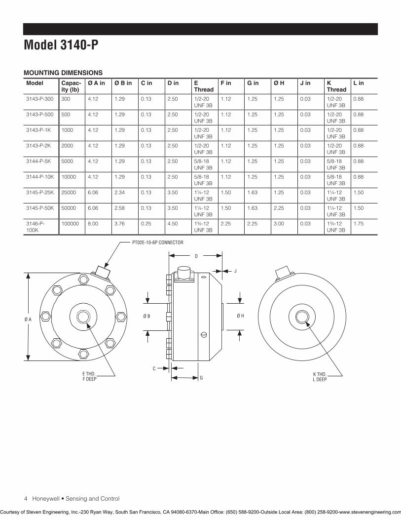
4Honeywell•SensingandControl
Model 3140-P
MOUNTING DIMENSIONS
Model Capac-ity (lb)
Ø A in Ø B in C in D in E Thread
F in G in Ø H J in K Thread
L in
3143-P-300 300 4.12 1.29 0.13 2.50 1/2-20UNF3B
1.12 1.25 1.25 0.03 1/2-20UNF3B
0.88
3143-P-500 500 4.12 1.29 0.13 2.50 1/2-20UNF3B
1.12 1.25 1.25 0.03 1/2-20UNF3B
0.88
3143-P-1K 1000 4.12 1.29 0.13 2.50 1/2-20UNF3B
1.12 1.25 1.25 0.03 1/2-20UNF3B
0.88
3143-P-2K 2000 4.12 1.29 0.13 2.50 1/2-20UNF3B
1.12 1.25 1.25 0.03 1/2-20UNF3B
0.88
3144-P-5K 5000 4.12 1.29 0.13 2.50 5/8-18UNF3B
1.12 1.25 1.25 0.03 5/8-18UNF3B
0.88
3144-P-10K 10000 4.12 1.29 0.13 2.50 5/8-18UNF3B
1.12 1.25 1.25 0.03 5/8-18UNF3B
0.88
3145-P-25K 25000 6.06 2.34 0.13 3.50 1¼-12UNF3B
1.50 1.63 1.25 0.03 1¼-12UNF3B
1.50
3145-P-50K 50000 6.06 2.58 0.13 3.50 1¼-12UNF3B
1.50 1.63 2.25 0.03 1¼-12UNF3B
1.50
3146-P-100K
100000 8.00 3.76 0.25 4.50 1¾-12UNF3B
2.25 2.25 3.00 0.03 1¾-12UNF3B
1.75
PT02E-10-6P CONNECTOR
J
L DEEPK THD.
D
Ø H
G
C
F DEEPE THD.
Ø BØ A
Courtesy of Steven Engineering, Inc.-230 Ryan Way, South San Francisco, CA 94080-6370-Main Office: (650) 588-9200-Outside Local Area: (800) 258-9200-www.stevenengineering.com
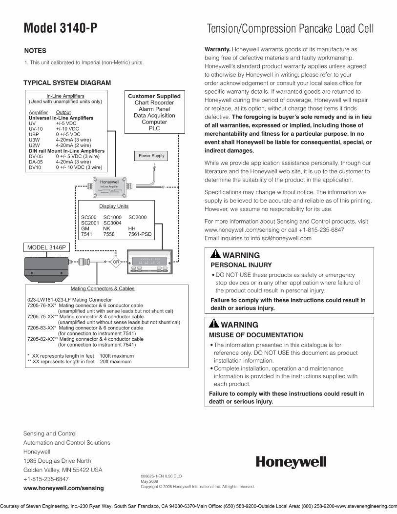
SensingandControl
AutomationandControlSolutions
Honeywell
1985DouglasDriveNorth
GoldenValley,MN55422USA
+1-815-235-6847
www.honeywell.com/sensing
008625-1-EN IL50 GLO May 2008Copyright © 2008 Honeywell International Inc. All rights reserved.
Model 3140-P Tension/Compression Pancake Load Cell
NOTES
1.ThisunitcalibratedtoImperial(non-Metric)units.
Warranty. Honeywellwarrantsgoodsofitsmanufactureasbeingfreeofdefectivematerialsandfaultyworkmanship.Honeywell’sstandardproductwarrantyappliesunlessagreedtootherwisebyHoneywellinwriting;pleaserefertoyourorderacknowledgementorconsultyourlocalsalesofficeforspecificwarrantydetails.IfwarrantedgoodsarereturnedtoHoneywellduringtheperiodofcoverage,Honeywellwillrepairorreplace,atitsoption,withoutchargethoseitemsitfindsdefective. The foregoing is buyer’s sole remedy and is in lieu of all warranties, expressed or implied, including those of merchantability and fitness for a particular purpose. In no event shall Honeywell be liable for consequential, special, or indirect damages.
Whileweprovideapplicationassistancepersonally,throughourliteratureandtheHoneywellwebsite,itisuptothecustomertodeterminethesuitabilityoftheproductintheapplication.
Specificationsmaychangewithoutnotice.Theinformationwesupplyisbelievedtobeaccurateandreliableasofthisprinting.However,weassumenoresponsibilityforitsuse.
FormoreinformationaboutSensingandControlproducts,visitwww.honeywell.com/sensingorcall+1-815-235-6847Emailinquiriestoinfo.sc@honeywell.com
WARNINGPERSONAL INJURY
•DONOTUSEtheseproductsassafetyoremergencystopdevicesorinanyotherapplicationwherefailureoftheproductcouldresultinpersonalinjury.
Failure to comply with these instructions could result in death or serious injury.
WARNINGMISUSE OF DOCUMENTATION
•Theinformationpresentedinthiscatalogueisforreferenceonly.DONOTUSEthisdocumentasproductinstallationinformation.•Completeinstallation,operationandmaintenanceinformationisprovidedintheinstructionssuppliedwitheachproduct.
Failure to comply with these instructions could result in death or serious injury.
TYPICAL SYSTEM DIAGRAM
HoneywellIn-Line Amplifier
Output InputSerial Number
Power Supply
Customer SuppliedChart Recorder
Alarm PanelData Acquisition
ComputerPLC
MODEL 3146P
(Used with unamplified units only)
UVUV-10UBPU3WU2W
DV-05DA-05DV10
In-Line Amplifiers
Amplifier Universal In-Line Amplifiers
DIN rail Mount In-Line Amplifiers
Output
+/-5 VDC+/-10 VDC0 +/-5 VDC4-20mA (3 wire)4-20mA (2 wire)
0 +/- 5 VDC (3 wire)4-20mA (3 wire)0 +/- 10 VDC (3 wire)
2003.1 lb.L1 L2 L3 L4
UP DOWN
VALUE CLEAR CHAN TARE
ENTERSETUP EXIT
SC500 SC1000 SC2000 SC2001 SC3004 GM NK HH7541 7558 7561-PSD
Display Units
023-LW181-023-LF Mating Connector7205-76-XX* Mating connector & 6 conductor cable (unamplified unit with sense leads but not shunt cal)7205-75-XX** Mating connector & 4 conductor cable (unamplified unit without sense leads but not shunt cal)7205-83-XX* Mating connector & 6 conductor cable (for connection to instrument 7541)7205-82-XX** Mating connector & 4 conductor cable (for connection to instrument 7541)
* XX represents length in feet 100ft maximum** XX represents length in feet 20ft maximum
Mating Connectors & Cables
OR
Courtesy of Steven Engineering, Inc.-230 Ryan Way, South San Francisco, CA 94080-6370-Main Office: (650) 588-9200-Outside Local Area: (800) 258-9200-www.stevenengineering.com

Tension/Compression Pancake Load CellModel 3167
DESCRIPTIONThese general purpose designs have exceptional structural
capability to withstand extraneous loads, such as torque,
bending moments, and side loads.
Available in capacities of 25 lb to 300 lb, they offer maximum
performance and enhanced accuracy.
Minimum deflection and compactness make these general-
purpose load cells easy to install and use.
FEATURES• Up to 0.05 % accuracy
• 25 lb to 300 lb range
• Integral cable (standard)
• Low sensitivity to extraneous loads
• Low deflection
• Built-in temperature compensation
Courtesy of Steven Engineering, Inc.-230 Ryan Way, South San Francisco, CA 94080-6370-Main Office: (650) 588-9200-Outside Local Area: (800) 258-9200-www.stevenengineering.com
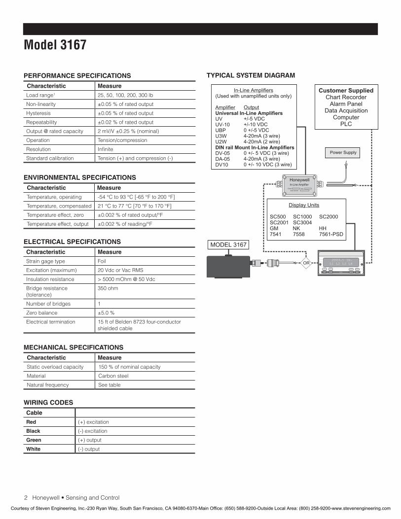
2 Honeywell • Sensing and Control
Model 3167
PERFORMANCE SPECIFICATIONS
Characteristic Measure
Load range1 25, 50, 100, 200, 300 lb
Non-linearity ±0.05 % of rated output
Hysteresis ±0.05 % of rated output
Repeatability ±0.02 % of rated output
Output @ rated capacity 2 mV/V ±0.25 % (nominal)
Operation Tension/compression
Resolution Infinite
Standard calibration Tension (+) and compression (-)
ENVIRONMENTAL SPECIFICATIONS
Characteristic Measure
Temperature, operating -54 °C to 93 °C [-65 °F to 200 °F]
Temperature, compensated 21 °C to 77 °C [70 °F to 170 °F]
Temperature effect, zero ±0.002 % of rated output/°F
Temperature effect, output ±0.002 % of reading/°F
ELECTRICAL SPECIFICATIONS
Characteristic Measure
Strain gage type Foil
Excitation (maximum) 20 Vdc or Vac RMS
Insulation resistance > 5000 mOhm @ 50 Vdc
Bridge resistance (tolerance)
350 ohm
Number of bridges 1
Zero balance ±5.0 %
Electrical termination 15 ft of Belden 8723 four-conductor shielded cable
MECHANICAL SPECIFICATIONS
Characteristic Measure
Static overload capacity 150 % of nominal capacity
Material Carbon steel
Natural frequency See table
WIRING CODES
Cable
Red (+) excitation
Black (-) excitation
Green (+) output
White (-) output
TYPICAL SYSTEM DIAGRAM
HoneywellIn-Line Amplifier
Output InputSerial Number
Power Supply
Customer SuppliedChart Recorder
Alarm PanelData Acquisition
ComputerPLC
MODEL 3167
(Used with unamplified units only)
UVUV-10UBPU3WU2W
DV-05DA-05DV10
In-Line Amplifiers
Amplifier Universal In-Line Amplifiers
DIN rail Mount In-Line Amplifiers
Output
+/-5 VDC+/-10 VDC0 +/-5 VDC4-20mA (3 wire)4-20mA (2 wire)
0 +/- 5 VDC (3 wire)4-20mA (3 wire)0 +/- 10 VDC (3 wire)
2003.1 lb.L1 L2 L3 L4
UP DOWN
VALUE CLEAR CHAN TARE
ENTERSETUP EXIT
SC500 SC1000 SC2000 SC2001 SC3004 GM NK HH7541 7558 7561-PSD
Display Units
OR
Courtesy of Steven Engineering, Inc.-230 Ryan Way, South San Francisco, CA 94080-6370-Main Office: (650) 588-9200-Outside Local Area: (800) 258-9200-www.stevenengineering.com
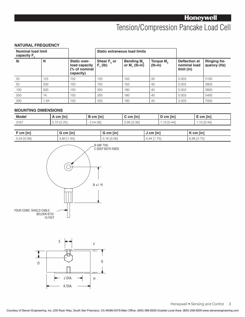
Honeywell • Sensing and Control 3
Tension/Compression Pancake Load Cell
NATURAL FREQUENCYNominal load limit capacity Fz
Static extraneous load limits
lb N Static over-load capacity (% of nominal capacity)
Shear FX or FY (lb)
Bending MX or MY (lb-in)
Torque MZ (lb-in)
Deflection at nominal load limit (in)
Ringing fre-quency (Hz)
25 125 150 150 150 40 0.003 2100
50 200 150 150 150 40 0.003 2800
100 500 150 250 180 40 0.003 3800
200 1K 150 250 180 40 0.003 5400
300 1.5K 150 250 180 40 0.003 7000
Model A cm [in] B cm [in] C cm [in] D cm [in] E cm [in]
3167 5,72 [2.25] - [1/4-28] 0,95 [0.38] 1,10 [0.44] 1,10 [0.44]
F cm [in] G cm [in] G cm [in] J cm [in] K cm [in]
0,24 [0.09] 3,80 [1.50] 0,16 [0.06] 4,44 [1.75] 6,98 [2.75]
MOUNTING DIMENSIONS
E
J DIA.
K DIA.
F
G
H
D
A +/- H
B UNF THD.C DEEP BOTH ENDS
FOUR COND. SHIELD CABLEBELDEN 8723
15 FEET
Courtesy of Steven Engineering, Inc.-230 Ryan Way, South San Francisco, CA 94080-6370-Main Office: (650) 588-9200-Outside Local Area: (800) 258-9200-www.stevenengineering.com

Sensing and Control
Automation and Control Solutions
Honeywell
1985 Douglas Drive North
Golden Valley, MN 55422 USA
+1-815-235-6847
www.honeywell.com/sensing
008622-1-EN IL50 GLO May 2008Copyright © 2008 Honeywell International Inc. All rights reserved.
Model 3167 Tension/Compression Pancake Load Cell
NOTES
1. This unit calibrated to Imperial (non-Metric) units.
Warranty. Honeywell warrants goods of its manufacture as being free of defective materials and faulty workmanship. Honeywell’s standard product warranty applies unless agreed to otherwise by Honeywell in writing; please refer to your order acknowledgement or consult your local sales office for specific warranty details. If warranted goods are returned to Honeywell during the period of coverage, Honeywell will repair or replace, at its option, without charge those items it finds defective. The foregoing is buyer’s sole remedy and is in lieu of all warranties, expressed or implied, including those of merchantability and fitness for a particular purpose. In no event shall Honeywell be liable for consequential, special, or indirect damages.
While we provide application assistance personally, through our literature and the Honeywell web site, it is up to the customer to determine the suitability of the product in the application.
Specifications may change without notice. The information we supply is believed to be accurate and reliable as of this printing. However, we assume no responsibility for its use.
For more information about Sensing and Control products, visit www.honeywell.com/sensing or call +1-815-235-6847Email inquiries to [email protected]
WARNINGPERSONAL INJURY•DONOTUSEtheseproductsassafetyoremergencystopdevicesorinanyotherapplicationwherefailureoftheproductcouldresultinpersonalinjury.
Failure to comply with these instructions could result in death or serious injury.
WARNINGMISUSE OF DOCUMENTATION•Theinformationpresentedinthiscatalogueisforreferenceonly.DONOTUSEthisdocumentasproductinstallationinformation.•Completeinstallation,operationandmaintenanceinformationisprovidedintheinstructionssuppliedwitheachproduct.
Failure to comply with these instructions could result in death or serious injury.
Courtesy of Steven Engineering, Inc.-230 Ryan Way, South San Francisco, CA 94080-6370-Main Office: (650) 588-9200-Outside Local Area: (800) 258-9200-www.stevenengineering.com
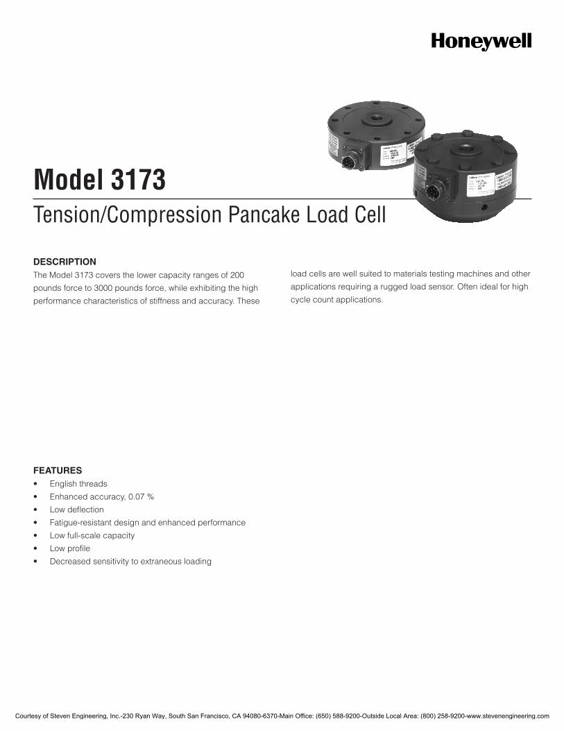
Tension/Compression Pancake Load CellModel 3173
DESCRIPTIONThe Model 3173 covers the lower capacity ranges of 200
pounds force to 3000 pounds force, while exhibiting the high
performance characteristics of stiffness and accuracy. These
load cells are well suited to materials testing machines and other
applications requiring a rugged load sensor. Often ideal for high
cycle count applications.
FEATURES• Englishthreads
• Enhancedaccuracy,0.07%
• Lowdeflection
• Fatigue-resistantdesignandenhancedperformance
• Lowfull-scalecapacity
• Lowprofile
• Decreasedsensitivitytoextraneousloading
Courtesy of Steven Engineering, Inc.-230 Ryan Way, South San Francisco, CA 94080-6370-Main Office: (650) 588-9200-Outside Local Area: (800) 258-9200-www.stevenengineering.com
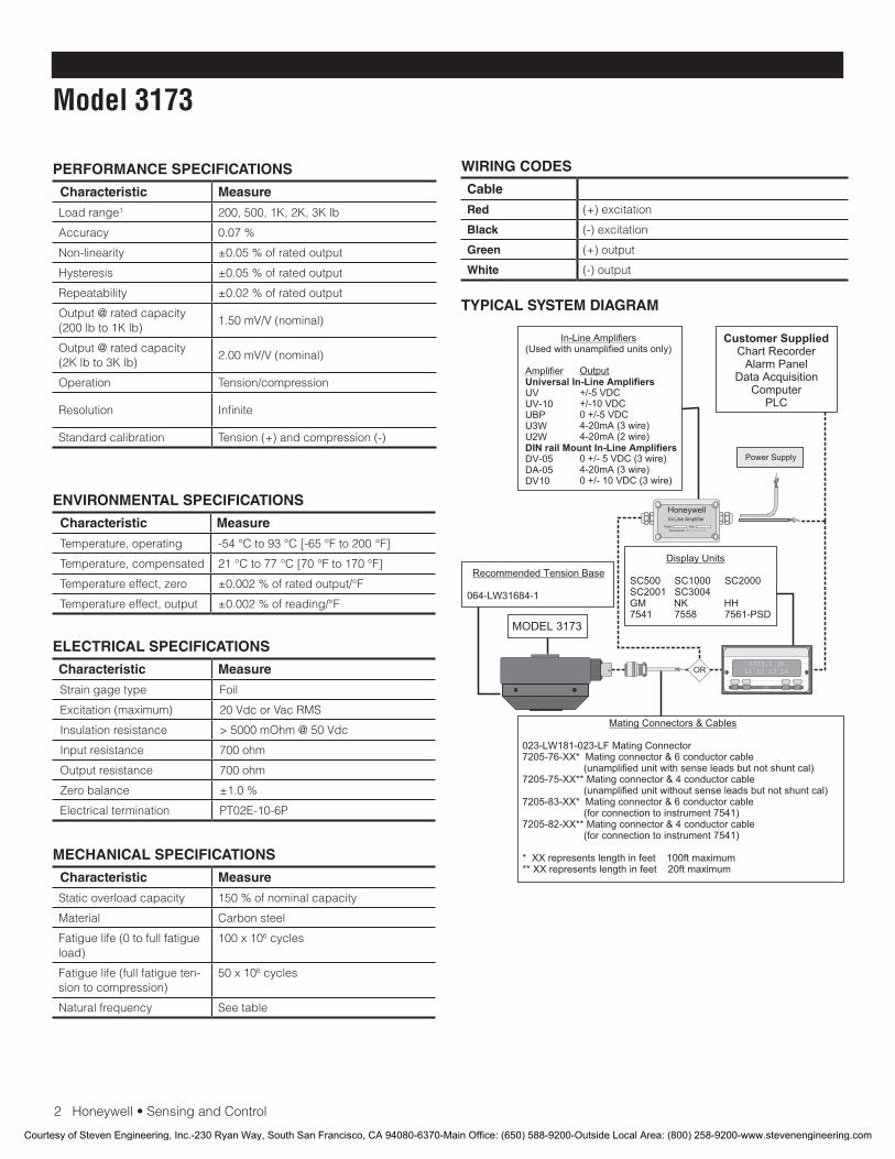
2Honeywell•SensingandControl
Model 3173
PERFORMANCE SPECIFICATIONS
Characteristic Measure
Loadrange1 200, 500, 1K, 2K, 3K lb
Accuracy 0.07%
Non-linearity ±0.05%ofratedoutput
Hysteresis ±0.05%ofratedoutput
Repeatability ±0.02%ofratedoutput
Output @ rated capacity (200 lb to 1K lb)
1.50 mV/V (nominal)
Output @ rated capacity (2K lb to 3K lb)
2.00 mV/V (nominal)
Operation Tension/compression
Resolution Infinite
Standardcalibration Tension(+)andcompression(-)
ENVIRONMENTAL SPECIFICATIONS
Characteristic Measure
Temperature, operating -54°Cto93°C[-65°Fto200°F]
Temperature, compensated 21°Cto77°C[70°Fto170°F]
Temperature effect, zero ±0.002%ofratedoutput/°F
Temperature effect, output ±0.002%ofreading/°F
ELECTRICAL SPECIFICATIONS
Characteristic Measure
Straingagetype Foil
Excitation(maximum) 20VdcorVacRMS
Insulation resistance > 5000 mOhm @ 50 Vdc
Input resistance 700 ohm
Output resistance 700 ohm
Zero balance ±1.0%
Electricaltermination PT02E-10-6P
MECHANICAL SPECIFICATIONS
Characteristic Measure
Staticoverloadcapacity 150%ofnominalcapacity
Material Carbonsteel
Fatiguelife(0tofullfatigueload)
100 x 106 cycles
Fatiguelife(fullfatigueten-sion to compression)
50 x 106 cycles
Natural frequency Seetable
WIRING CODES
Cable
Red (+) excitation
Black (-)excitation
Green (+) output
White (-)output
TYPICAL SYSTEM DIAGRAM
HoneywellIn-Line Amplifier
Output InputSerial Number
Power Supply
Customer SuppliedChart Recorder
Alarm PanelData Acquisition
ComputerPLC
MODEL 3173
(Used with unamplified units only)
UVUV-10UBPU3WU2W
DV-05DA-05DV10
In-Line Amplifiers
Amplifier Universal In-Line Amplifiers
DIN rail Mount In-Line Amplifiers
Output
+/-5 VDC+/-10 VDC0 +/-5 VDC4-20mA (3 wire)4-20mA (2 wire)
0 +/- 5 VDC (3 wire)4-20mA (3 wire)0 +/- 10 VDC (3 wire)
2003.1 lb.L1 L2 L3 L4
UP DOWN
VALUE CLEAR CHAN TARE
ENTERSETUP EXIT
023-LW181-023-LF Mating Connector7205-76-XX* Mating connector & 6 conductor cable (unamplified unit with sense leads but not shunt cal)7205-75-XX** Mating connector & 4 conductor cable (unamplified unit without sense leads but not shunt cal)7205-83-XX* Mating connector & 6 conductor cable (for connection to instrument 7541)7205-82-XX** Mating connector & 4 conductor cable (for connection to instrument 7541)
* XX represents length in feet 100ft maximum** XX represents length in feet 20ft maximum
Mating Connectors & Cables
SC500 SC1000 SC2000 SC2001 SC3004 GM NK HH7541 7558 7561-PSD
Display Units
064-LW31684-1
Recommended Tension Base
OR
Courtesy of Steven Engineering, Inc.-230 Ryan Way, South San Francisco, CA 94080-6370-Main Office: (650) 588-9200-Outside Local Area: (800) 258-9200-www.stevenengineering.com
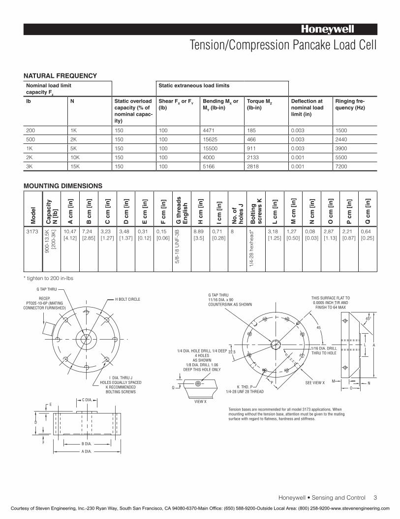
Honeywell•SensingandControl3
Tension/Compression Pancake Load Cell
NATURAL FREQUENCYNominal load limit capacity Fz
Static extraneous load limits
lb N Static overload capacity (% of nominal capac-ity)
Shear FX or FY (lb)
Bending MX or MY (lb-in)
Torque MZ (lb-in)
Deflection at nominal load limit (in)
Ringing fre-quency (Hz)
200 1K 150 100 4471 185 0.003 1500
500 2K 150 100 15625 466 0.003 2440
1K 5K 150 100 15500 911 0.003 3900
2K 10K 150 100 4000 2133 0.001 5500
3K 15K 150 100 5166 2818 0.001 7200
MOUNTING DIMENSIONS
Mo
del
Cap
acit
y N
[lb
]
A c
m [
in]
B c
m [
in]
C c
m [
in]
D c
m [
in]
E c
m [
in]
F c
m [
in]
G t
hre
ads
En
glis
h
H c
m [
in]
I cm
[in
]
No
. of
ho
les
J
Bo
ltin
g
scre
ws
K
L c
m [
in]
M c
m [
in]
N c
m [
in]
O c
m [
in]
P c
m [
in]
Q c
m [
in]
3173
900-13
.5K
[200
-3K] 10,47
[4.12]7,24[2.85]
3,23 [1.27]
3,48[1.37]
0,31 [0.12]
0,15 [0.06]
5/8-18
UNF-3B 8.89
[3.5]0,71 [0.28]
8
1/4-28
hex
head
* 3,18 [1.25]
1,27 [0.50]
0,08 [0.03]
2,87 [1.13]
2,21 [0.87]
0,64[0.25]
*tightento200in-lbs
Courtesy of Steven Engineering, Inc.-230 Ryan Way, South San Francisco, CA 94080-6370-Main Office: (650) 588-9200-Outside Local Area: (800) 258-9200-www.stevenengineering.com

SensingandControl
AutomationandControlSolutions
Honeywell
1985DouglasDriveNorth
GoldenValley,MN55422USA
+1-815-235-6847
www.honeywell.com/sensing
008618-1-EN IL50 GLO May 2008Copyright © 2008 Honeywell International Inc. All rights reserved.
Model 3173 Tension/Compression Pancake Load Cell
Warranty. Honeywell warrants goods of its manufacture as being free of defective materials and faulty workmanship. Honeywell’s standard product warranty applies unless agreed to otherwise by Honeywell in writing; please refer to your orderacknowledgementorconsultyourlocalsalesofficeforspecificwarrantydetails.IfwarrantedgoodsarereturnedtoHoneywell during the period of coverage, Honeywell will repair orreplace,atitsoption,withoutchargethoseitemsitfindsdefective. The foregoing is buyer’s sole remedy and is in lieu of all warranties, expressed or implied, including those of merchantability and fitness for a particular purpose. In no event shall Honeywell be liable for consequential, special, or indirect damages.
While we provide application assistance personally, through our literature and the Honeywell web site, it is up to the customer to determine the suitability of the product in the application.
Specificationsmaychangewithoutnotice.Theinformationwesupply is believed to be accurate and reliable as of this printing. However, we assume no responsibility for its use.
FormoreinformationaboutSensingandControlproducts,visitwww.honeywell.com/sensingorcall+1-815-235-6847Emailinquiriestoinfo.sc@honeywell.com
WARNINGPERSONAL INJURY•DONOTUSEtheseproductsassafetyoremergencystopdevicesorinanyotherapplicationwherefailureoftheproductcouldresultinpersonalinjury.
Failure to comply with these instructions could result in death or serious injury.
WARNINGMISUSE OF DOCUMENTATION•Theinformationpresentedinthiscatalogueisforreferenceonly.DONOTUSEthisdocumentasproductinstallationinformation.•Completeinstallation,operationandmaintenanceinformationisprovidedintheinstructionssuppliedwitheachproduct.
Failure to comply with these instructions could result in death or serious injury.
NOTES
1.ThisunitcalibratedtoImperial(non-Metric)units.
Courtesy of Steven Engineering, Inc.-230 Ryan Way, South San Francisco, CA 94080-6370-Main Office: (650) 588-9200-Outside Local Area: (800) 258-9200-www.stevenengineering.com
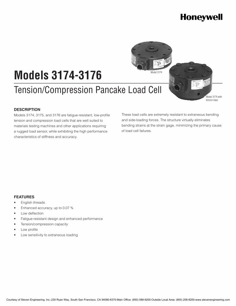
Tension/Compression Pancake Load CellModels 3174-3176
DESCRIPTIONModels 3174, 3175, and 3176 are fatigue-resistant, low-profile
tension and compression load cells that are well suited to
materials testing machines and other applications requiring
a rugged load sensor, while exhibiting the high performance
characteristics of stiffness and accuracy.
These load cells are extremely resistant to extraneous bending
and side-loading forces. The structure virtually eliminates
bending strains at the strain gage, minimizing the primary cause
of load cell failures.
FEATURES• Englishthreads
• Enhancedaccuracy,upto0.07%
• Lowdeflection
• Fatigue-resistantdesignandenhancedperformance
• Tension/compressioncapacity
• Lowprofile
• Lowsensitivitytoextraneousloading
Model 3174
Model 3174 with tension base
Courtesy of Steven Engineering, Inc.-230 Ryan Way, South San Francisco, CA 94080-6370-Main Office: (650) 588-9200-Outside Local Area: (800) 258-9200-www.stevenengineering.com

2Honeywell•SensingandControl
Model 3174-3176
PERFORMANCE SPECIFICATIONS
Characteristic Measure
Loadrange1 5K,10K,20K,50K,100Klb
Non-linearity ±0.05%ofratedoutput
Hysteresis ±0.05%ofratedoutput
Repeatability ±0.02%ofratedoutput
Output @ rated capacity 2.00mV/V(nominal)
Creep ±0.025%ofratedoutput
Resolution Infinite
Standardcalibration Tension(+)andcompression(-)
ENVIRONMENTAL SPECIFICATIONS
Characteristic Measure
Temperature, operating -54°Cto93°C[-65°Fto200°F]
Temperature, compensated 21°Cto77°C[70°Fto170°F]
Temperature effect, zero ±0.002%ofratedoutput/°F
Temperature effect, output ±0.002%ofreading/°F
ELECTRICAL SPECIFICATIONS
Characteristic Measure
Straingagetype Foil
Excitation(maximum) 20VdcorVacRMS
Insulation resistance >5000mOhm@50Vdc
Bridge resistance 700ohm
Number of bridges 1
Zero balance ±1.0%
Electricaltermination PT02E-10-6P
MECHANICAL SPECIFICATIONS
Characteristic Measure
Staticoverloadcapacity 150%ofnominalcapacity
Material Carbonsteel
Fatiguelife(0tofullfatigueload)
100x106 cycles
Fatiguelife(fullfatigueten-siontocompression)
50x106 cycles
Natural frequency Seetable
WIRING CODES
Cable
Red (+)excitation
Black (-)excitation
Green (+)output
White (-)output
TYPICAL SYSTEM DIAGRAM
HoneywellIn-Line Amplifier
Output Input
Serial Number
Power Supply
Customer SuppliedChart Recorder
Alarm PanelData Acquisition
ComputerPLC
MODEL 3174
(Used with unamplified units only)
UVUV-10UBPU3WU2W
DV-05DA-05DV10
In-Line Amplifiers
AmplifierUniversal In-Line Amplifiers
DIN rail Mount In-Line Amplifiers
Output
4-20mA (3 wire)4-20mA (2 wire)
4-20mA (3 wire)
2003.1 lb.L1 L2 L3 L4
UP DOWN
VALUE CLEAR CHAN TARE
ENTERSETUP EXIT
SC500 SC1000 SC2000SC2001 SC3004GM NK HH7541 7558 7561-PSD
Display Units
023-LW181-023-LF Mating Connector7205-76-XX* Mating connector & 6 conductor cable (unamplified unit with sense leads but not shunt cal)7205-75-XX** Mating connector & 4 conductor cable (unamplified unit without sense leads but not shunt cal)7205-83-XX* Mating connector & 6 conductor cable (for connection to instrument 7541)7205-82-XX** Mating connector & 4 conductor cable (for connection to instrument 7541)
* XX represents length in feet 100ft maximum** XX represents length in feet 20ft maximum
Mating Connectors & Cables
064-LW30774-1
Recommended Tension Base
OR
±5 Vdc±10 Vdc0 ±5 Vdc
0 ±5 Vdc (3 wire)
0 ±10 Vdc (3 wire)
Courtesy of Steven Engineering, Inc.-230 Ryan Way, South San Francisco, CA 94080-6370-Main Office: (650) 588-9200-Outside Local Area: (800) 258-9200-www.stevenengineering.com
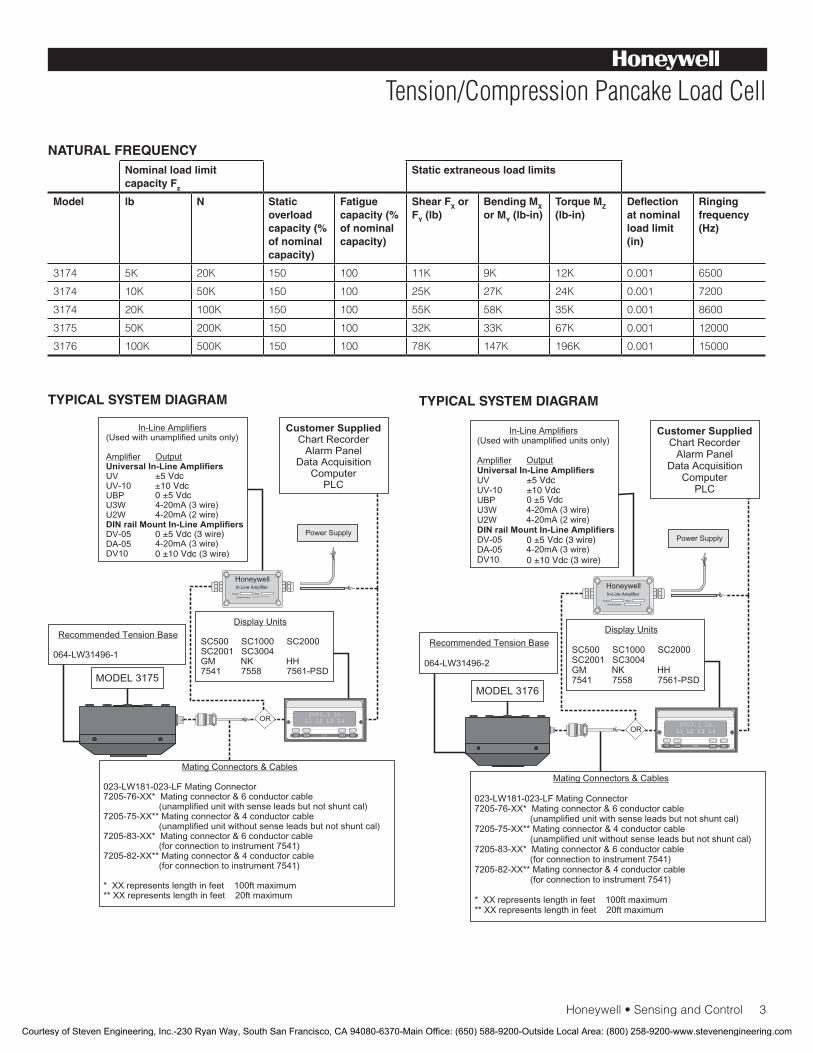
Honeywell•SensingandControl3
Tension/Compression Pancake Load Cell
NATURAL FREQUENCYNominal load limit capacity Fz
Static extraneous load limits
Model lb N Static overload capacity (% of nominal capacity)
Fatigue capacity (% of nominal capacity)
Shear FX or FY (lb)
Bending MX or MY (lb-in)
Torque MZ (lb-in)
Deflection at nominal load limit (in)
Ringing frequency (Hz)
3174 5K 20K 150 100 11K 9K 12K 0.001 6500
3174 10K 50K 150 100 25K 27K 24K 0.001 7200
3174 20K 100K 150 100 55K 58K 35K 0.001 8600
3175 50K 200K 150 100 32K 33K 67K 0.001 12000
3176 100K 500K 150 100 78K 147K 196K 0.001 15000
HoneywellIn-Line Amplifier
Output Input
Serial Number
Power Supply
Customer SuppliedChart Recorder
Alarm PanelData Acquisition
ComputerPLC
MODEL 3175
(Used with unamplified units only)
UVUV-10UBPU3WU2W
DV-05DA-05DV10
In-Line Amplifiers
AmplifierUniversal In-Line Amplifiers
DIN rail Mount In-Line Amplifiers
Output
4-20mA (3 wire)4-20mA (2 wire)
4-20mA (3 wire)
2003.1 lb.L1 L2 L3 L4
UP DOWN
VALUE CLEAR CHAN TARE
ENTERSETUP EXIT
SC500 SC1000 SC2000SC2001 SC3004GM NK HH7541 7558 7561-PSD
Display Units
023-LW181-023-LF Mating Connector7205-76-XX* Mating connector & 6 conductor cable (unamplified unit with sense leads but not shunt cal)7205-75-XX** Mating connector & 4 conductor cable (unamplified unit without sense leads but not shunt cal)7205-83-XX* Mating connector & 6 conductor cable (for connection to instrument 7541)7205-82-XX** Mating connector & 4 conductor cable (for connection to instrument 7541)
* XX represents length in feet 100ft maximum** XX represents length in feet 20ft maximum
Mating Connectors & Cables
064-LW31496-1
Recommended Tension Base
OR
0 ±5 Vdc
±5 Vdc±10 Vdc
0 ±5 Vdc (3 wire)
0 ±10 Vdc (3 wire)
HoneywellIn-Line Amplifier
Output Input
Serial Number
Power Supply
Customer SuppliedChart Recorder
Alarm PanelData Acquisition
ComputerPLC
MODEL 3176
(Used with unamplified units only)
UVUV-10UBPU3WU2W
DV-05DA-05DV10
In-Line Amplifiers
AmplifierUniversal In-Line Amplifiers
DIN rail Mount In-Line Amplifiers
Output
4-20mA (3 wire)4-20mA (2 wire)
4-20mA (3 wire)
2003.1 lb.L1 L2 L3 L4
UP DOWN
VALUE CLEAR CHAN TARE
ENTERSETUP EXIT
SC500 SC1000 SC2000SC2001 SC3004GM NK HH7541 7558 7561-PSD
Display Units
023-LW181-023-LF Mating Connector7205-76-XX* Mating connector & 6 conductor cable (unamplified unit with sense leads but not shunt cal)7205-75-XX** Mating connector & 4 conductor cable (unamplified unit without sense leads but not shunt cal)7205-83-XX* Mating connector & 6 conductor cable (for connection to instrument 7541)7205-82-XX** Mating connector & 4 conductor cable (for connection to instrument 7541)
* XX represents length in feet 100ft maximum** XX represents length in feet 20ft maximum
Mating Connectors & Cables
064-LW31496-2
Recommended Tension Base
OR
±5 Vdc±10 Vdc0 ±5 Vdc
0 ±5 Vdc (3 wire)
0 ±10 Vdc (3 wire)
TYPICAL SYSTEM DIAGRAM TYPICAL SYSTEM DIAGRAM
Courtesy of Steven Engineering, Inc.-230 Ryan Way, South San Francisco, CA 94080-6370-Main Office: (650) 588-9200-Outside Local Area: (800) 258-9200-www.stevenengineering.com
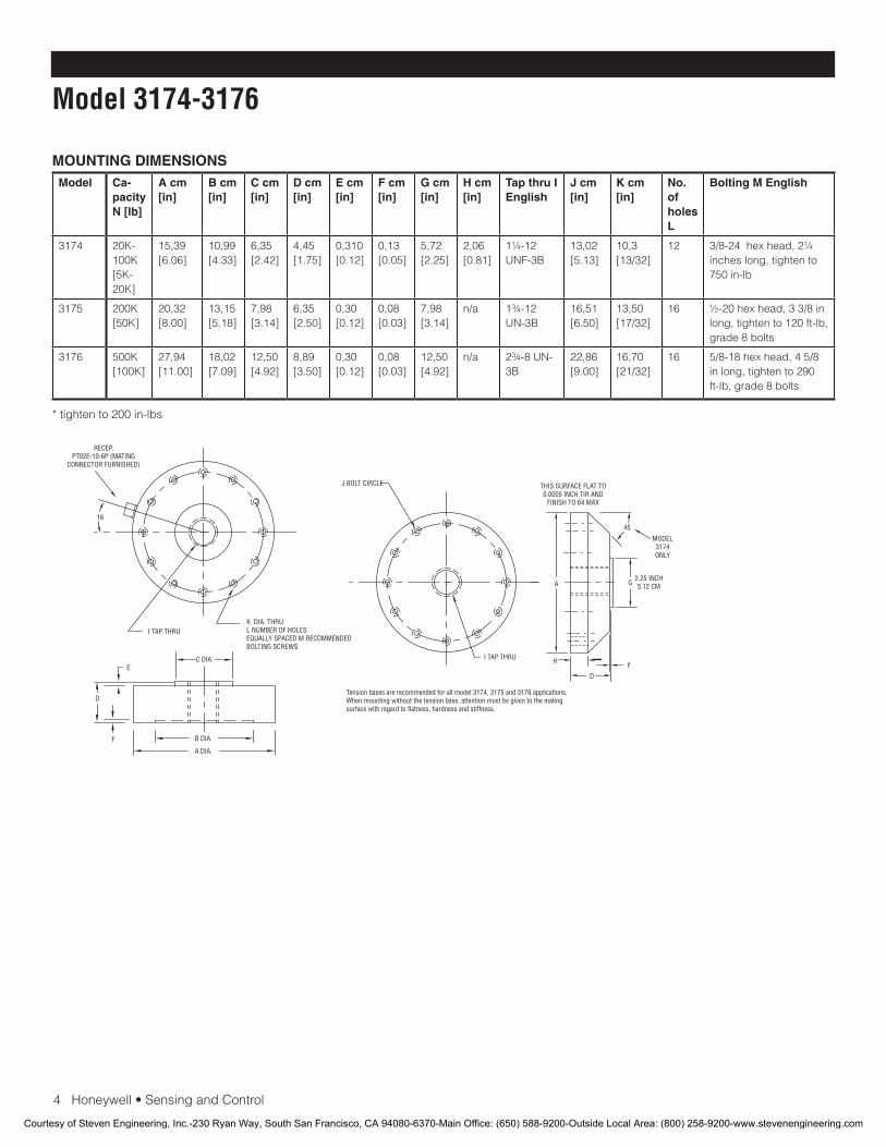
4Honeywell•SensingandControl
Model 3174-3176
MOUNTING DIMENSIONSModel Ca-
pacity N [lb]
A cm [in]
B cm [in]
C cm [in]
D cm [in]
E cm [in]
F cm [in]
G cm [in]
H cm [in]
Tap thru I English
J cm [in]
K cm [in]
No. of holes L
Bolting M English
3174 20K-100K[5K-20K]
15,39[6.06]
10,99[4.33]
6,35 [2.42]
4,45 [1.75]
0,310[0.12]
0,13[0.05]
5,72 [2.25]
2,06[0.81]
1¼-12 UNF-3B
13,02[5.13]
10,3[13/32]
12 3/8-24hexhead,2¼inches long, tighten to 750in-lb
3175 200K[50K]
20,32[8.00]
13,15 [5.18]
7,98[3.14]
6,35 [2.50]
0,30[0.12]
0,08[0.03]
7,98[3.14]
n/a 1¾-12 UN-3B
16,51 [6.50]
13,50[17/32]
16 ½-20hexhead,33/8inlong,tightento120ft-lb,grade 8 bolts
3176 500K[100K]
27,94[11.00]
18,02[7.09]
12,50[4.92]
8,89[3.50]
0,30[0.12]
0,08[0.03]
12,50[4.92]
n/a 2¾-8 UN-3B
22,86 [9.00]
16,70[21/32]
16 5/8-18hexhead,45/8inlong,tightento290ft-lb, grade 8 bolts
*tightento200in-lbs
G
K DIA. THRU L NUMBER OF HOLESEQUALLY SPACED M RECOMMENDEDBOLTING SCREWS
RECEP.PT02E-10-6P (MATING
CONNECTOR FURNISHED)
A DIA.
B DIA.
C DIA.
F
E
D
J BOLT CIRCLE
45
A
F
D
H
Tension bases are recommended for all model 3174, 3175 and 3176 applications.When mounting without the tension base, attention must be given to the matingsurface with regard to flatness, hardness and stiffness.
I TAP THRU
16
MODEL3174ONLY
2.25 INCH5.12 CM
I TAP THRU
THIS SURFACE FLAT TO0.0005 INCH TIR AND
FINISH TO 64 MAX
Courtesy of Steven Engineering, Inc.-230 Ryan Way, South San Francisco, CA 94080-6370-Main Office: (650) 588-9200-Outside Local Area: (800) 258-9200-www.stevenengineering.com
SensingandControl
AutomationandControlSolutions
Honeywell
1985DouglasDriveNorth
GoldenValley,MN55422USA
+1-815-235-6847
www.honeywell.com/sensing
008619-1-EN IL50 GLO May 2008Copyright © 2008 Honeywell International Inc. All rights reserved.
Model 3174-3176 Tension/Compression Pancake Load Cell
NOTES
1.ThisunitcalibratedtoImperial(non-Metric)units.
Warranty. Honeywell warrants goods of its manufacture as being free of defective materials and faulty workmanship. Honeywell’s standard product warranty applies unless agreed to otherwise by Honeywell in writing; please refer to your order acknowledgement or consult your local sales office for specific warranty details. If warranted goods are returned to Honeywell during the period of coverage, Honeywell will repair or replace, at its option, without charge those items it finds defective. The foregoing is buyer’s sole remedy and is in lieu of all warranties, expressed or implied, including those of merchantability and fitness for a particular purpose. In no event shall Honeywell be liable for consequential, special, or indirect damages.
While we provide application assistance personally, through our literature and the Honeywell web site, it is up to the customer to determine the suitability of the product in the application.
Specificationsmaychangewithoutnotice.Theinformationwesupply is believed to be accurate and reliable as of this printing. However, we assume no responsibility for its use.
FormoreinformationaboutSensingandControlproducts,visitwww.honeywell.com/sensingorcall+1-815-235-6847Emailinquiriestoinfo.sc@honeywell.com
WARNINGPERSONAL INJURY•DONOTUSEtheseproductsassafetyoremergencystopdevicesorinanyotherapplicationwherefailureoftheproductcouldresultinpersonalinjury.
Failure to comply with these instructions could result in death or serious injury.
WARNINGMISUSE OF DOCUMENTATION•Theinformationpresentedinthiscatalogueisforreferenceonly.DONOTUSEthisdocumentasproductinstallationinformation.•Completeinstallation,operationandmaintenanceinformationisprovidedintheinstructionssuppliedwitheachproduct.
Failure to comply with these instructions could result in death or serious injury.
Courtesy of Steven Engineering, Inc.-230 Ryan Way, South San Francisco, CA 94080-6370-Main Office: (650) 588-9200-Outside Local Area: (800) 258-9200-www.stevenengineering.com
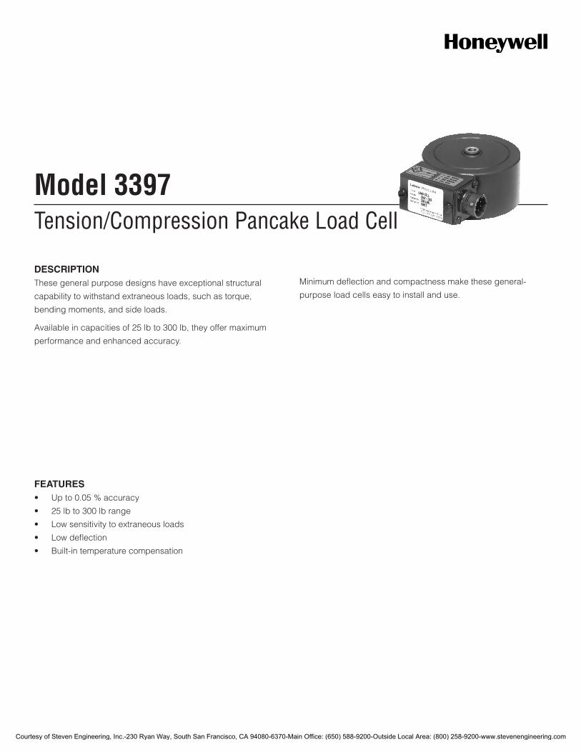
Tension/Compression Pancake Load CellModel 3397
DESCRIPTIONThese general purpose designs have exceptional structural
capability to withstand extraneous loads, such as torque,
bending moments, and side loads.
Available in capacities of 25 lb to 300 lb, they offer maximum
performance and enhanced accuracy.
Minimum deflection and compactness make these general-
purpose load cells easy to install and use.
FEATURES• Upto0.05%accuracy
• 25lbto300lbrange
• Lowsensitivitytoextraneousloads
• Lowdeflection
• Built-intemperaturecompensation
Courtesy of Steven Engineering, Inc.-230 Ryan Way, South San Francisco, CA 94080-6370-Main Office: (650) 588-9200-Outside Local Area: (800) 258-9200-www.stevenengineering.com
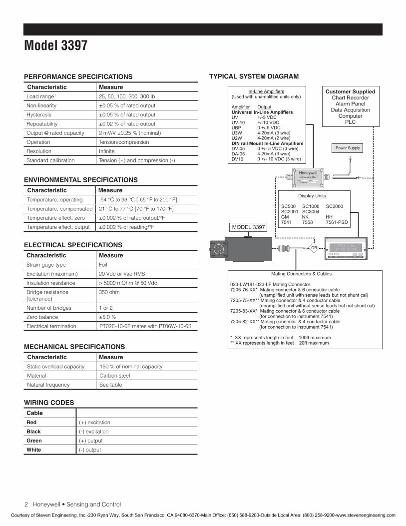
2Honeywell•SensingandControl
Model 3397
PERFORMANCE SPECIFICATIONS
Characteristic Measure
Loadrange1 25, 50, 100, 200, 300 lb
Non-linearity ±0.05%ofratedoutput
Hysteresis ±0.05%ofratedoutput
Repeatability ±0.02%ofratedoutput
Output @ rated capacity 2mV/V±0.25%(nominal)
Operation Tension/compression
Resolution Infinite
Standardcalibration Tension(+)andcompression(-)
ENVIRONMENTAL SPECIFICATIONS
Characteristic Measure
Temperature, operating -54°Cto93°C[-65°Fto200°F]
Temperature, compensated 21°Cto77°C[70°Fto170°F]
Temperature effect, zero ±0.002%ofratedoutput/°F
Temperature effect, output ±0.002%ofreading/°F
ELECTRICAL SPECIFICATIONS
Characteristic Measure
Straingagetype Foil
Excitation(maximum) 20VdcorVacRMS
Insulation resistance > 5000 mOhm @ 50 Vdc
Bridgeresistance(tolerance)
350 ohm
Number of bridges 1 or 2
Zero balance ±5.0%
Electrical termination PT02E-10-6PmateswithPT06W-10-6S
MECHANICAL SPECIFICATIONS
Characteristic Measure
Staticoverloadcapacity 150%ofnominalcapacity
Material Carbonsteel
Natural frequency Seetable
WIRING CODES
Cable
Red (+)excitation
Black (-)excitation
Green (+)output
White (-)output
TYPICAL SYSTEM DIAGRAM
HoneywellIn-Line Amplifier
Output Input
Serial Number
Power Supply
Customer SuppliedChart Recorder
Alarm PanelData Acquisition
ComputerPLC
MODEL 3397
(Used with unamplified units only)
UVUV-10UBPU3WU2W
DV-05DA-05DV10
In-Line Amplifiers
AmplifierUniversal In-Line Amplifiers
DIN rail Mount In-Line Amplifiers
Output
+/-5 VDC+/-10 VDC0 +/-5 VDC4-20mA (3 wire)4-20mA (2 wire)
0 +/- 5 VDC (3 wire)4-20mA (3 wire)0 +/- 10 VDC (3 wire)
2003.1 lb.L1 L2 L3 L4
UP DOWN
VALUE CLEAR CHAN TARE
ENTERSETUP EXIT
SC500 SC1000 SC2000SC2001 SC3004GM NK HH7541 7558 7561-PSD
Display Units
023-LW181-023-LF Mating Connector7205-76-XX* Mating connector & 6 conductor cable (unamplified unit with sense leads but not shunt cal)7205-75-XX** Mating connector & 4 conductor cable (unamplified unit without sense leads but not shunt cal)7205-83-XX* Mating connector & 6 conductor cable (for connection to instrument 7541)7205-82-XX** Mating connector & 4 conductor cable (for connection to instrument 7541)
* XX represents length in feet 100ft maximum** XX represents length in feet 20ft maximum
Mating Connectors & Cables
OR
Courtesy of Steven Engineering, Inc.-230 Ryan Way, South San Francisco, CA 94080-6370-Main Office: (650) 588-9200-Outside Local Area: (800) 258-9200-www.stevenengineering.com
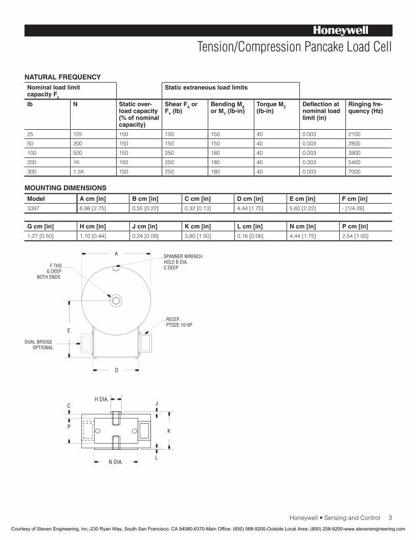
Honeywell•SensingandControl3
Tension/Compression Pancake Load Cell
NATURAL FREQUENCYNominal load limit capacity Fz
Static extraneous load limits
lb N Static over-load capacity (% of nominal capacity)
Shear FX or FY (lb)
Bending MX or MY (lb-in)
Torque MZ (lb-in)
Deflection at nominal load limit (in)
Ringing fre-quency (Hz)
25 125 150 150 150 40 0.003 2100
50 200 150 150 150 40 0.003 2800
100 500 150 250 180 40 0.003 3800
200 1K 150 250 180 40 0.003 5400
300 1.5K 150 250 180 40 0.003 7000
Model A cm [in] B cm [in] C cm [in] D cm [in] E cm [in] F cm [in]
3397 6,98[2.75] 0,55[0.22] 0,32[0.13] 4,44[1.75] 5,60[2.22] -[1/4-28]
G cm [in] H cm [in] J cm [in] K cm [in] L cm [in] N cm [in] P cm [in]
1,27[0.50] 1,10[0.44] 0,24[0.09] 3,80[1.50] 0,16[0.06] 4,44[1.75] 2,54[1.00]
MOUNTING DIMENSIONS
A
D
H DIA.
N DIA.
J
K
L
P
C
E
SPANNER WRENCHHOLE B DIA.C DEEPF THD.
G DEEPBOTH ENDS
RECEP.PTO2E-10-6P
DUAL BRIDGEOPTIONAL
Courtesy of Steven Engineering, Inc.-230 Ryan Way, South San Francisco, CA 94080-6370-Main Office: (650) 588-9200-Outside Local Area: (800) 258-9200-www.stevenengineering.com
SensingandControl
AutomationandControlSolutions
Honeywell
1985DouglasDriveNorth
GoldenValley,MN55422USA
+1-815-235-6847
www.honeywell.com/sensing
008623-1-EN IL50 GLO May 2008Copyright © 2008 Honeywell International Inc. All rights reserved.
Model 3397 Tension/Compression Pancake Load Cell
NOTES
1.ThisunitcalibratedtoImperial(non-Metric)units.
Warranty. Honeywell warrants goods of its manufacture as being free of defective materials and faulty workmanship. Honeywell’s standard product warranty applies unless agreed to otherwise by Honeywell in writing; please refer to your order acknowledgement or consult your local sales office for specific warranty details. If warranted goods are returned to Honeywell during the period of coverage, Honeywell will repair or replace, at its option, without charge those items it finds defective. The foregoing is buyer’s sole remedy and is in lieu of all warranties, expressed or implied, including those of merchantability and fitness for a particular purpose. In no event shall Honeywell be liable for consequential, special, or indirect damages.
Whileweprovideapplicationassistancepersonally,throughourliterature and the Honeywell web site, it is up to the customer to determine the suitability of the product in the application.
Specificationsmaychangewithoutnotice.Theinformationwesupply is believed to be accurate and reliable as of this printing. However, we assume no responsibility for its use.
FormoreinformationaboutSensingandControlproducts,visitwww.honeywell.com/sensingorcall+1-815-235-6847Email inquiries to [email protected]
WARNINGPERSONAL INJURY•DONOTUSEtheseproductsassafetyoremergencystopdevicesorinanyotherapplicationwherefailureoftheproductcouldresultinpersonalinjury.
Failure to comply with these instructions could result in death or serious injury.
WARNINGMISUSE OF DOCUMENTATION•Theinformationpresentedinthiscatalogueisforreferenceonly.DONOTUSEthisdocumentasproductinstallationinformation.•Completeinstallation,operationandmaintenanceinformationisprovidedintheinstructionssuppliedwitheachproduct.
Failure to comply with these instructions could result in death or serious injury.
Courtesy of Steven Engineering, Inc.-230 Ryan Way, South San Francisco, CA 94080-6370-Main Office: (650) 588-9200-Outside Local Area: (800) 258-9200-www.stevenengineering.com
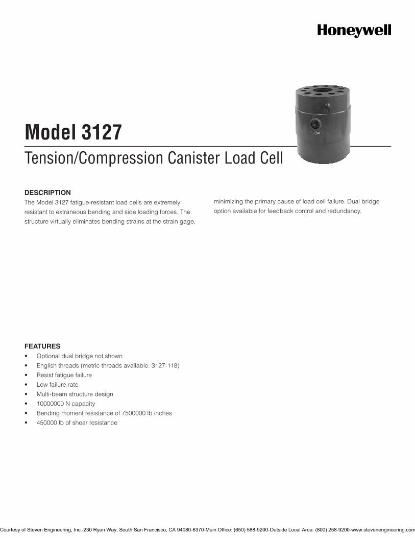
Tension/Compression Canister Load CellModel 3127
FEATURES• Optionaldualbridgenotshown
• Englishthreads(metricthreadsavailable:3127-118)
• Resistfatiguefailure
• Lowfailurerate
• Multi-beamstructuredesign
• 10000000Ncapacity
• Bendingmomentresistanceof7500000lbinches
• 450000lbofshearresistance
DESCRIPTIONTheModel3127fatigue-resistantloadcellsareextremely
resistanttoextraneousbendingandsideloadingforces.The
structurevirtuallyeliminatesbendingstrainsatthestraingage,
minimizingtheprimarycauseofloadcellfailure.Dualbridge
optionavailableforfeedbackcontrolandredundancy.
Courtesy of Steven Engineering, Inc.-230 Ryan Way, South San Francisco, CA 94080-6370-Main Office: (650) 588-9200-Outside Local Area: (800) 258-9200-www.stevenengineering.com
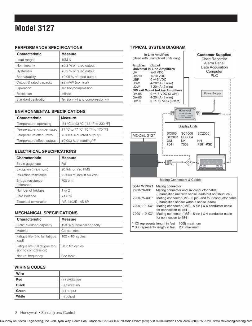
2Honeywell•SensingandControl
Model 3127
PERFORMANCE SPECIFICATIONS
Characteristic Measure
Loadrange1 10MN
Non-linearity ±0.2%ofratedoutput
Hysteresis ±0.2%ofratedoutput
Repeatability ±0.05%ofratedoutput
Output@ratedcapacity ±2mV/V(nominal)
Operation Tension/compression
Resolution Infinite
Standardcalibration Tension(+)andcompression(-)
ENVIRONMENTAL SPECIFICATIONS
Characteristic Measure
Temperature,operating -54°Cto93°C[-65°Fto200°F]
Temperature,compensated 21°Cto77°C[70°Fto170°F]
Temperatureeffect,zero ±0.003%ofratedoutput/°F
Temperatureeffect,output ±0.003%ofreading/°F
ELECTRICAL SPECIFICATIONS
Characteristic Measure
Straingagetype Foil
Excitation(maximum) 20VdcorVacRMS
Insulationresistance >5000mOhm@50Vdc
Bridgeresistance(tolerance)
700ohm
Numberofbridges 1or2
Zerobalance ±1.0%
Electricaltermination MS-3102E-14S-5P
MECHANICAL SPECIFICATIONS
Characteristic Measure
Staticoverloadcapacity 150%ofnominalcapacity
Material Carbonsteel
Fatiguelife(0tofullfatigueload)
100x106cycles
Fatiguelife(fullfatigueten-siontocompression)
50x106cycles
Naturalfrequency Seetable
WIRING CODES
Wire
Red (+)excitation
Black (-)excitation
Green (+)output
White (-)output
TYPICAL SYSTEM DIAGRAM
HoneywellIn-Line Amplifier
Output Input
Serial Number
Power Supply
Customer SuppliedChart Recorder
Alarm PanelData Acquisition
ComputerPLC
MODEL 3127
(Used with unamplified units only)
UVUV-10UBPU3WU2W
DV-05DA-05DV10
In-Line Amplifiers
AmplifierUniversal In-Line Amplifiers
DIN rail Mount In-Line Amplifiers
Output
+/-5 VDC+/-10 VDC0 +/-5 VDC4-20mA (3 wire)4-20mA (2 wire)
0 +/- 5 VDC (3 wire)4-20mA (3 wire)0 +/- 10 VDC (3 wire)
2003.1 lb.L1 L2 L3 L4
UP DOWN
VALUE CLEAR CHAN TARE
ENTERSETUP EXIT
SC500 SC1000 SC2000SC2001 SC3004GM NK HH7541 7558 7561-PSD
Display Units
* XX represents length in feet 100ft maximum** XX represents length in feet 20ft maximum
Mating Connectors & Cables
OR
064-LW13621 Mating connector7200-76-XX* Mating connector and six conductor cable (unamplified unit with sense leads but not shunt cal)7200-75-XX** Mating connector (MS - 5 pin) and four conductor cable (unamplified sensor without sense leads)7200-111-XX** Mating connector ( MS – 5 pin ) & 6 conductor cable for connection to 7541 7200-110-XX** Mating connector ( MS – 5 pin ) & 4 conductor cable for connection to 7541
Courtesy of Steven Engineering, Inc.-230 Ryan Way, South San Francisco, CA 94080-6370-Main Office: (650) 588-9200-Outside Local Area: (800) 258-9200-www.stevenengineering.com
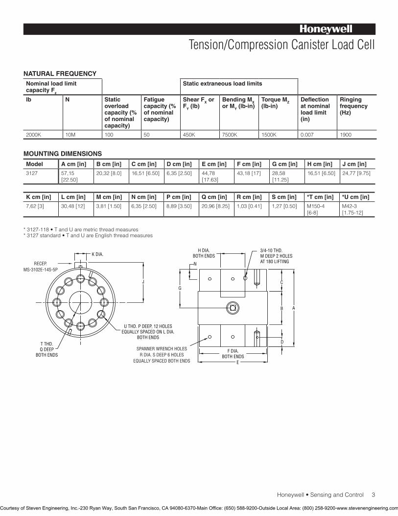
Honeywell•SensingandControl3
Tension/Compression Canister Load Cell
NATURAL FREQUENCYNominal load limit capacity Fz
Static extraneous load limits
lb N Static overload capacity (% of nominal capacity)
Fatigue capacity (% of nominal capacity)
Shear FX or FY (lb)
Bending MX or MY (lb-in)
Torque MZ (lb-in)
Deflection at nominal load limit (in)
Ringing frequency (Hz)
2000K 10M 100 50 450K 7500K 1500K 0.007 1900
Model A cm [in] B cm [in] C cm [in] D cm [in] E cm [in] F cm [in] G cm [in] H cm [in] J cm [in]
3127 57,15[22.50]
20,32[8.0] 16,51[6.50] 6,35[2.50] 44,78[17.63]
43,18[17] 28,58[11.25]
16,51[6.50] 24,77[9.75]
K cm [in] L cm [in] M cm [in] N cm [in] P cm [in] Q cm [in] R cm [in] S cm [in] *T cm [in] *U cm [in]
7,62[3] 30,48[12] 3,81[1.50] 6,35[2.50] 8,89[3.50] 20,96[8.25] 1,03[0.41] 1,27[0.50] M150-4[6-8]
M42-3[1.75-12]
*3127-118•TandUaremetricthreadmeasures*3127standard•TandUareEnglishthreadmeasures
MOUNTING DIMENSIONS
K DIA.
T THD.Q DEEP
BOTH ENDS
JG
H DIA.BOTH ENDS
N
3/4-10 THD.M DEEP 2 HOLESAT 180 LIFTING
C
D
F DIA.BOTH ENDS
E
B A
U THD. P DEEP, 12 HOLESEQUALLY SPACED ON L DIA.
BOTH ENDS
SPANNER WRENCH HOLESR DIA. S DEEP 6 HOLES
EQUALLY SPACED BOTH ENDS
RECEP.MS-3102E-14S-5P
Courtesy of Steven Engineering, Inc.-230 Ryan Way, South San Francisco, CA 94080-6370-Main Office: (650) 588-9200-Outside Local Area: (800) 258-9200-www.stevenengineering.com

SensingandControl
AutomationandControlSolutions
Honeywell
1985DouglasDriveNorth
GoldenValley,MN55422USA
+1-815-235-6847
www.honeywell.com/sensing
008646-1-EN IL50 GLO May 2008Copyright © 2008 Honeywell International Inc. All rights reserved.
Model 3127 Tension/Compression Canister Load Cell
NOTES
1.ThisunitcalibratedtoImperial(non-Metric)units.
Warranty. Honeywellwarrantsgoodsofitsmanufactureasbeingfreeofdefectivematerialsandfaultyworkmanship.Honeywell’sstandardproductwarrantyappliesunlessagreedtootherwisebyHoneywellinwriting;pleaserefertoyourorderacknowledgementorconsultyourlocalsalesofficeforspecificwarrantydetails.IfwarrantedgoodsarereturnedtoHoneywellduringtheperiodofcoverage,Honeywellwillrepairorreplace,atitsoption,withoutchargethoseitemsitfindsdefective.The foregoing is buyer’s sole remedy and is in lieu of all warranties, expressed or implied, including those of merchantability and fitness for a particular purpose. In no event shall Honeywell be liable for consequential, special, or indirect damages.
Whileweprovideapplicationassistancepersonally,throughourliteratureandtheHoneywellwebsite,itisuptothecustomertodeterminethesuitabilityoftheproductintheapplication.
Specificationsmaychangewithoutnotice.Theinformationwesupplyisbelievedtobeaccurateandreliableasofthisprinting.However,weassumenoresponsibilityforitsuse.
FormoreinformationaboutSensingandControlproducts,visitwww.honeywell.com/sensingorcall+1-815-235-6847Emailinquiriestoinfo.sc@honeywell.com
WARNINGPERSONAL INJURY•DONOTUSEtheseproductsassafetyoremergencystopdevicesorinanyotherapplicationwherefailureoftheproductcouldresultinpersonalinjury.
Failure to comply with these instructions could result in death or serious injury.
WARNINGMISUSE OF DOCUMENTATION•Theinformationpresentedinthiscatalogueisforreferenceonly.DONOTUSEthisdocumentasproductinstallationinformation.•Completeinstallation,operationandmaintenanceinformationisprovidedintheinstructionssuppliedwitheachproduct.
Failure to comply with these instructions could result in death or serious injury.
Courtesy of Steven Engineering, Inc.-230 Ryan Way, South San Francisco, CA 94080-6370-Main Office: (650) 588-9200-Outside Local Area: (800) 258-9200-www.stevenengineering.com
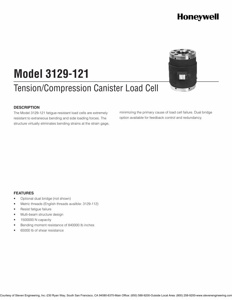
Tension/Compression Canister Load CellModel 3129-121
FEATURES• Optionaldualbridge(notshown)
• Metricthreads(Englishthreadsavailble:3129-112)
• Resistfatiguefailure
• Multi-beamstructuredesign
• 1500000Ncapacity
• Bendingmomentresistanceof840000lbinches
• 65000lbofshearresistance
DESCRIPTIONTheModel3129-121fatigue-resistantloadcellsareextremely
resistanttoextraneousbendingandsideloadingforces.The
structurevirtuallyeliminatesbendingstrainsatthestraingage,
minimizingtheprimarycauseofloadcellfailure.Dualbridge
optionavailableforfeedbackcontrolandredundancy.
Courtesy of Steven Engineering, Inc.-230 Ryan Way, South San Francisco, CA 94080-6370-Main Office: (650) 588-9200-Outside Local Area: (800) 258-9200-www.stevenengineering.com
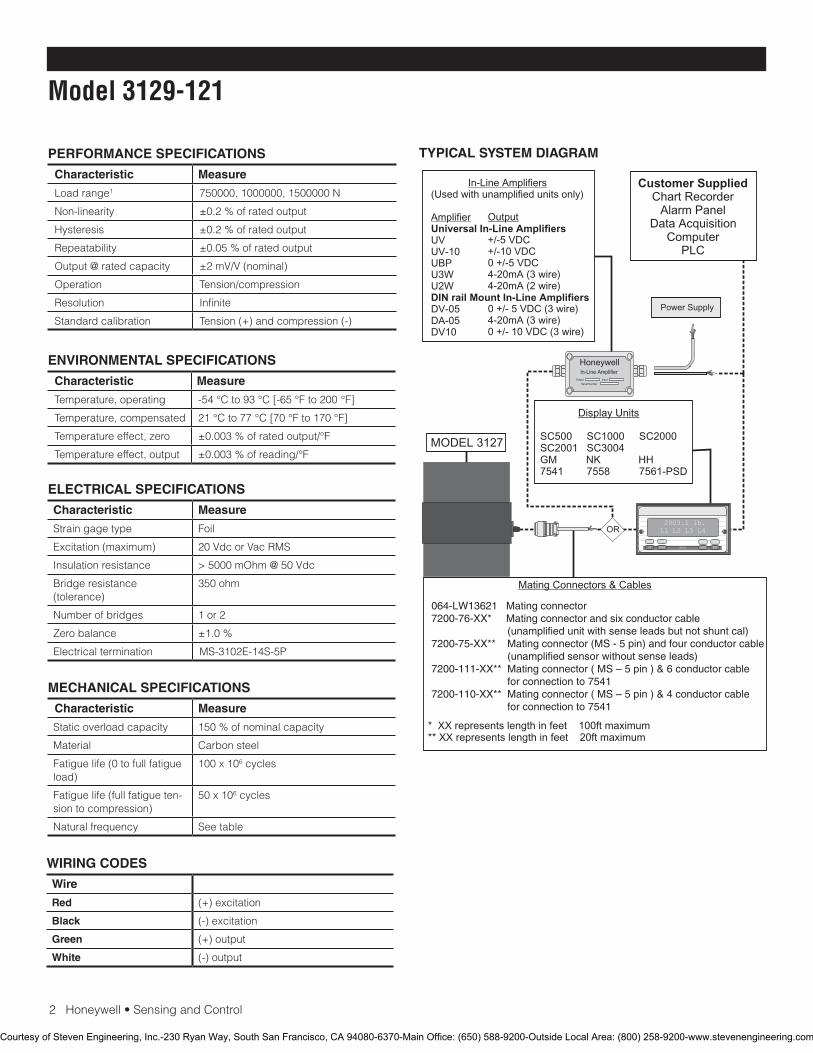
2Honeywell•SensingandControl
Model 3129-121
PERFORMANCE SPECIFICATIONS
Characteristic Measure
Loadrange1 750000,1000000,1500000N
Non-linearity ±0.2%ofratedoutput
Hysteresis ±0.2%ofratedoutput
Repeatability ±0.05%ofratedoutput
Output@ratedcapacity ±2mV/V(nominal)
Operation Tension/compression
Resolution Infinite
Standardcalibration Tension(+)andcompression(-)
ENVIRONMENTAL SPECIFICATIONS
Characteristic Measure
Temperature,operating -54°Cto93°C[-65°Fto200°F]
Temperature,compensated 21°Cto77°C[70°Fto170°F]
Temperatureeffect,zero ±0.003%ofratedoutput/°F
Temperatureeffect,output ±0.003%ofreading/°F
ELECTRICAL SPECIFICATIONS
Characteristic Measure
Straingagetype Foil
Excitation(maximum) 20VdcorVacRMS
Insulationresistance >5000mOhm@50Vdc
Bridgeresistance(tolerance)
350ohm
Numberofbridges 1or2
Zerobalance ±1.0%
Electricaltermination MS-3102E-14S-5P
MECHANICAL SPECIFICATIONS
Characteristic Measure
Staticoverloadcapacity 150%ofnominalcapacity
Material Carbonsteel
Fatiguelife(0tofullfatigueload)
100x106cycles
Fatiguelife(fullfatigueten-siontocompression)
50x106cycles
Naturalfrequency Seetable
WIRING CODES
Wire
Red (+)excitation
Black (-)excitation
Green (+)output
White (-)output
TYPICAL SYSTEM DIAGRAM
HoneywellIn-Line Amplifier
Output Input
Serial Number
Power Supply
Customer SuppliedChart Recorder
Alarm PanelData Acquisition
ComputerPLC
MODEL 3127
(Used with unamplified units only)
UVUV-10UBPU3WU2W
DV-05DA-05DV10
In-Line Amplifiers
AmplifierUniversal In-Line Amplifiers
DIN rail Mount In-Line Amplifiers
Output
+/-5 VDC+/-10 VDC0 +/-5 VDC4-20mA (3 wire)4-20mA (2 wire)
0 +/- 5 VDC (3 wire)4-20mA (3 wire)0 +/- 10 VDC (3 wire)
2003.1 lb.L1 L2 L3 L4
UP DOWN
VALUE CLEAR CHAN TARE
ENTERSETUP EXIT
SC500 SC1000 SC2000SC2001 SC3004GM NK HH7541 7558 7561-PSD
Display Units
* XX represents length in feet 100ft maximum** XX represents length in feet 20ft maximum
Mating Connectors & Cables
OR
064-LW13621 Mating connector7200-76-XX* Mating connector and six conductor cable (unamplified unit with sense leads but not shunt cal)7200-75-XX** Mating connector (MS - 5 pin) and four conductor cable (unamplified sensor without sense leads)7200-111-XX** Mating connector ( MS – 5 pin ) & 6 conductor cable for connection to 7541 7200-110-XX** Mating connector ( MS – 5 pin ) & 4 conductor cable for connection to 7541
Courtesy of Steven Engineering, Inc.-230 Ryan Way, South San Francisco, CA 94080-6370-Main Office: (650) 588-9200-Outside Local Area: (800) 258-9200-www.stevenengineering.com

Honeywell•SensingandControl3
Tension/Compression Canister Load Cell
NATURAL FREQUENCYNominal load limit capacity Fz
Static extraneous load limits
lb N Static overload capacity (% of nominal capacity)
Fatigue capacity (% of nominal capacity)
Shear FX or FY (lb)
Bending MX or MY (lb-in)
Torque MZ (lb-in)
Deflection at nominal load limit (in)
Ringing frequency (Hz)
150K 750K 150 75 40K 625K 150K 0.004 3000
200K 1M 150 75 55K 730K 260K 0.004 3400
300K 1.5M 150 75 65K 840K 236K 0.004 4100
Model A cm [in] B cm [in] C cm [in] D cm [in] E cm [in] F cm [in]
3129 25,4[10] 17,78[7] 3,81[1.50] 10,8[4.25] 19,05[7.50] 12,70[5]
G cm [in] H cm [in] J cm [in] K cm [in] L cm [in] *M cm [in] *N cm [in]
6,35[2.50] 12,7[5] 3,81[1.50] 13,97[5.50] 8,41[3.31] M27-2[1-8] M76-2[3-12]
*3129-121•MandNaremetricthreadmeasures*3129-112standard•MandNareEnglishthreadmeasures
MOUNTING DIMENSIONS
SPANNER WRENCH HOLES13/32 DIA. 3/8 DEEP
6 HOLES EQUALLY SPACEDAT BOTH ENDS
RECEP.MS-3102E-14S-5P
A
K
J
E
L DIA.
B DIA.
C
D
N THD.3.0 DEEP
BOTH ENDS
G
F
M THD. 1/2 DEEP8 HOLES EQUALLY SPACEDON H DIA.
Courtesy of Steven Engineering, Inc.-230 Ryan Way, South San Francisco, CA 94080-6370-Main Office: (650) 588-9200-Outside Local Area: (800) 258-9200-www.stevenengineering.com

SensingandControl
AutomationandControlSolutions
Honeywell
1985DouglasDriveNorth
GoldenValley,MN55422USA
+1-815-235-6847
www.honeywell.com/sensing
008647-1-EN IL50 GLO May 2008Copyright © 2008 Honeywell International Inc. All rights reserved.
Model 3129-121 Tension/Compression Canister Load Cell
NOTES
1.ThisunitcalibratedtoImperial(non-Metric)units.
Warranty. Honeywellwarrantsgoodsofitsmanufactureasbeingfreeofdefectivematerialsandfaultyworkmanship.Honeywell’sstandardproductwarrantyappliesunlessagreedtootherwisebyHoneywellinwriting;pleaserefertoyourorderacknowledgementorconsultyourlocalsalesofficeforspecificwarrantydetails.IfwarrantedgoodsarereturnedtoHoneywellduringtheperiodofcoverage,Honeywellwillrepairorreplace,atitsoption,withoutchargethoseitemsitfindsdefective.The foregoing is buyer’s sole remedy and is in lieu of all warranties, expressed or implied, including those of merchantability and fitness for a particular purpose. In no event shall Honeywell be liable for consequential, special, or indirect damages.
Whileweprovideapplicationassistancepersonally,throughourliteratureandtheHoneywellwebsite,itisuptothecustomertodeterminethesuitabilityoftheproductintheapplication.
Specificationsmaychangewithoutnotice.Theinformationwesupplyisbelievedtobeaccurateandreliableasofthisprinting.However,weassumenoresponsibilityforitsuse.
FormoreinformationaboutSensingandControlproducts,visitwww.honeywell.com/sensingorcall+1-815-235-6847Emailinquiriestoinfo.sc@honeywell.com
WARNINGPERSONAL INJURY•DONOTUSEtheseproductsassafetyoremergencystopdevicesorinanyotherapplicationwherefailureoftheproductcouldresultinpersonalinjury.
Failure to comply with these instructions could result in death or serious injury.
WARNINGMISUSE OF DOCUMENTATION•Theinformationpresentedinthiscatalogueisforreferenceonly.DONOTUSEthisdocumentasproductinstallationinformation.•Completeinstallation,operationandmaintenanceinformationisprovidedintheinstructionssuppliedwitheachproduct.
Failure to comply with these instructions could result in death or serious injury.
Courtesy of Steven Engineering, Inc.-230 Ryan Way, South San Francisco, CA 94080-6370-Main Office: (650) 588-9200-Outside Local Area: (800) 258-9200-www.stevenengineering.com
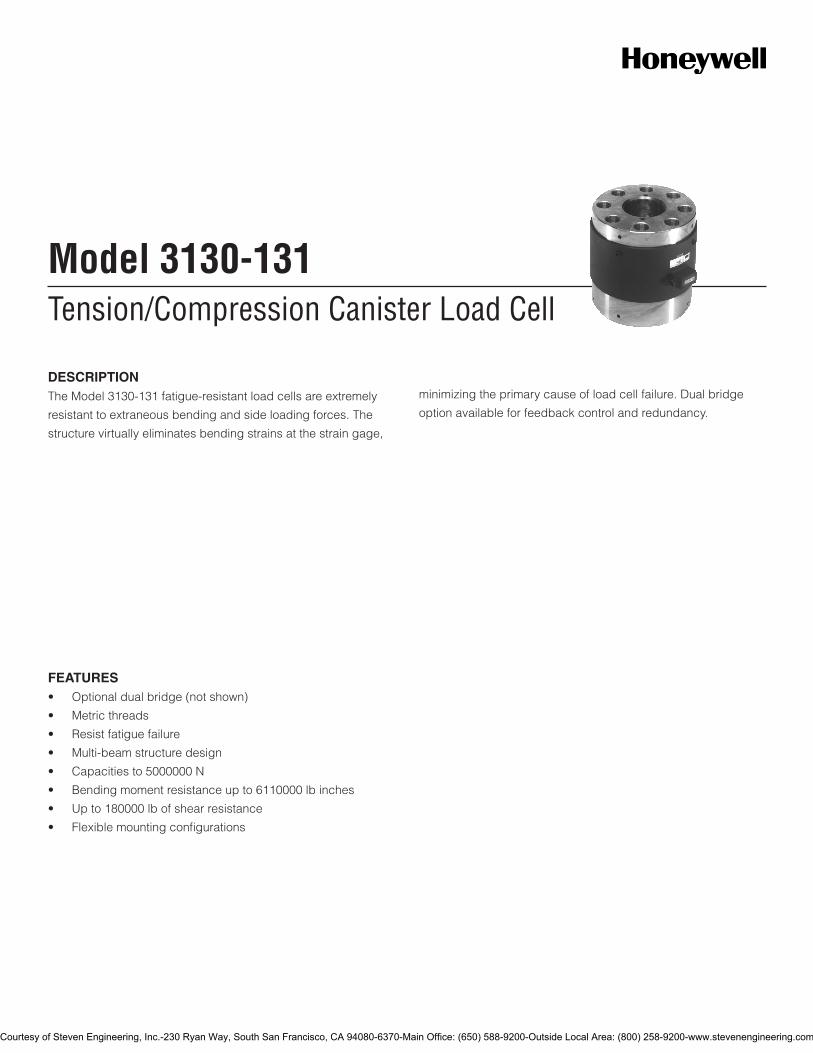
Tension/Compression Canister Load CellModel 3130-131
DESCRIPTIONThe Model 3130-131 fatigue-resistant load cells are extremely
resistant to extraneous bending and side loading forces. The
structure virtually eliminates bending strains at the strain gage,
minimizing the primary cause of load cell failure. Dual bridge
option available for feedback control and redundancy.
FEATURES• Optionaldualbridge(notshown)
• Metricthreads
• Resistfatiguefailure
• Multi-beamstructuredesign
• Capacitiesto5000000N
• Bendingmomentresistanceupto6110000lbinches
• Upto180000lbofshearresistance
• Flexiblemountingconfigurations
Courtesy of Steven Engineering, Inc.-230 Ryan Way, South San Francisco, CA 94080-6370-Main Office: (650) 588-9200-Outside Local Area: (800) 258-9200-www.stevenengineering.com
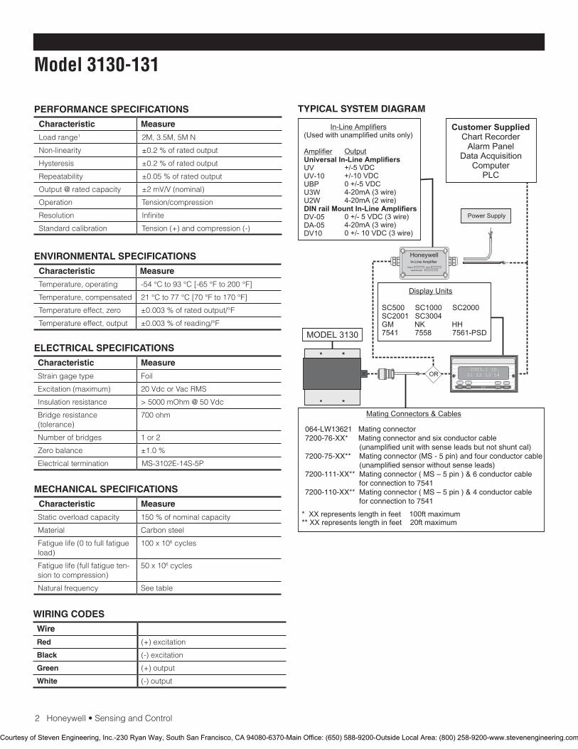
2Honeywell•SensingandControl
Model 3130-131
PERFORMANCE SPECIFICATIONS
Characteristic Measure
Load range1 2M,3.5M,5MN
Non-linearity ±0.2 % of rated output
Hysteresis ±0.2 % of rated output
Repeatability ±0.05%ofratedoutput
Output@ratedcapacity ±2mV/V(nominal)
Operation Tension/compression
Resolution Infinite
Standardcalibration Tension(+)andcompression(-)
ENVIRONMENTAL SPECIFICATIONS
Characteristic Measure
Temperature, operating -54°Cto93°C[-65°Fto200°F]
Temperature, compensated 21°Cto77°C[70°Fto170°F]
Temperature effect, zero ±0.003%ofratedoutput/°F
Temperature effect, output ±0.003%ofreading/°F
ELECTRICAL SPECIFICATIONS
Characteristic Measure
Straingagetype Foil
Excitation(maximum) 20VdcorVacRMS
Insulation resistance >5000mOhm@50Vdc
Bridgeresistance(tolerance)
700ohm
Numberofbridges 1 or 2
Zero balance ±1.0 %
Electrical termination MS-3102E-14S-5P
MECHANICAL SPECIFICATIONS
Characteristic Measure
Staticoverloadcapacity 150%ofnominalcapacity
Material Carbonsteel
Fatiguelife(0tofullfatigueload)
100 x 106 cycles
Fatiguelife(fullfatigueten-siontocompression)
50x106 cycles
Naturalfrequency Seetable
WIRING CODES
Wire
Red (+)excitation
Black (-)excitation
Green (+)output
White (-)output
TYPICAL SYSTEM DIAGRAM
HoneywellIn-Line Amplifier
Output Input
Serial Number
Power Supply
Customer SuppliedChart Recorder
Alarm PanelData Acquisition
ComputerPLC
MODEL 3130
(Used with unamplified units only)
UVUV-10UBPU3WU2W
DV-05DA-05DV10
In-Line Amplifiers
AmplifierUniversal In-Line Amplifiers
DIN rail Mount In-Line Amplifiers
Output
+/-5 VDC+/-10 VDC0 +/-5 VDC4-20mA (3 wire)4-20mA (2 wire)
0 +/- 5 VDC (3 wire)4-20mA (3 wire)0 +/- 10 VDC (3 wire)
2003.1 lb.L1 L2 L3 L4
UP DOWN
VALUE CLEAR CHAN TARE
ENTERSETUP EXIT
SC500 SC1000 SC2000SC2001 SC3004GM NK HH7541 7558 7561-PSD
Display Units
* XX represents length in feet 100ft maximum** XX represents length in feet 20ft maximum
Mating Connectors & Cables
OR
064-LW13621 Mating connector7200-76-XX* Mating connector and six conductor cable (unamplified unit with sense leads but not shunt cal)7200-75-XX** Mating connector (MS - 5 pin) and four conductor cable (unamplified sensor without sense leads)7200-111-XX** Mating connector ( MS – 5 pin ) & 6 conductor cable for connection to 7541 7200-110-XX** Mating connector ( MS – 5 pin ) & 4 conductor cable for connection to 7541
Courtesy of Steven Engineering, Inc.-230 Ryan Way, South San Francisco, CA 94080-6370-Main Office: (650) 588-9200-Outside Local Area: (800) 258-9200-www.stevenengineering.com
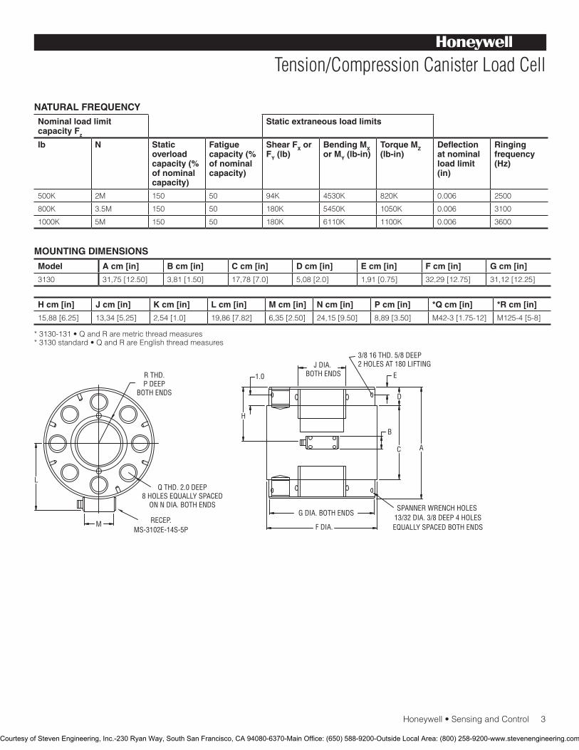
Honeywell•SensingandControl3
Tension/Compression Canister Load Cell
NATURAL FREQUENCYNominal load limit capacity Fz
Static extraneous load limits
lb N Static overload capacity (% of nominal capacity)
Fatigue capacity (% of nominal capacity)
Shear FX or FY (lb)
Bending MX or MY (lb-in)
Torque MZ (lb-in)
Deflection at nominal load limit (in)
Ringing frequency (Hz)
500K 2M 150 50 94K 4530K 820K 0.006 2500
800K 3.5M 150 50 180K 5450K 1050K 0.006 3100
1000K 5M 150 50 180K 6110K 1100K 0.006 3600
Model A cm [in] B cm [in] C cm [in] D cm [in] E cm [in] F cm [in] G cm [in]
3130 31,75[12.50] 3,81[1.50] 17,78[7.0] 5,08[2.0] 1,91[0.75] 32,29[12.75] 31,12[12.25]
H cm [in] J cm [in] K cm [in] L cm [in] M cm [in] N cm [in] P cm [in] *Q cm [in] *R cm [in]
15,88[6.25] 13,34[5.25] 2,54[1.0] 19,86[7.82] 6,35[2.50] 24,15[9.50] 8,89[3.50] M42-3[1.75-12] M125-4[5-8]
*3130-131•QandRaremetricthreadmeasures*3130standard•QandRareEnglishthreadmeasures
MOUNTING DIMENSIONS
Q THD. 2.0 DEEP8 HOLES EQUALLY SPACED
ON N DIA. BOTH ENDS
R THD.P DEEP
BOTH ENDS
1.0
H
3/8 16 THD. 5/8 DEEP2 HOLES AT 180 LIFTING
E
D
B
C A
G DIA. BOTH ENDS
F DIA.
L
M
J DIA. BOTH ENDS
RECEP.MS-3102E-14S-5P
SPANNER WRENCH HOLES 13/32 DIA. 3/8 DEEP 4 HOLESEQUALLY SPACED BOTH ENDS
Courtesy of Steven Engineering, Inc.-230 Ryan Way, South San Francisco, CA 94080-6370-Main Office: (650) 588-9200-Outside Local Area: (800) 258-9200-www.stevenengineering.com
SensingandControl
AutomationandControlSolutions
Honeywell
1985DouglasDriveNorth
GoldenValley,MN55422USA
+1-815-235-6847
www.honeywell.com/sensing
008644-1-EN IL50 GLO May 2008Copyright © 2008 Honeywell International Inc. All rights reserved.
Model 3130-131 Tension/Compression Canister Load Cell
NOTES
1.ThisunitcalibratedtoImperial(non-Metric)units.
Warranty. Honeywellwarrantsgoodsofitsmanufactureasbeingfreeofdefectivematerialsandfaultyworkmanship.Honeywell’sstandardproductwarrantyappliesunlessagreedtootherwisebyHoneywellinwriting;pleaserefertoyourorderacknowledgementorconsultyourlocalsalesofficeforspecificwarrantydetails.IfwarrantedgoodsarereturnedtoHoneywellduringtheperiodofcoverage,Honeywellwillrepairorreplace,atitsoption,withoutchargethoseitemsitfindsdefective. The foregoing is buyer’s sole remedy and is in lieu of all warranties, expressed or implied, including those of merchantability and fitness for a particular purpose. In no event shall Honeywell be liable for consequential, special, or indirect damages.
Whileweprovideapplicationassistancepersonally,throughourliteratureandtheHoneywellwebsite,itisuptothecustomertodetermine the suitability of the product in the application.
Specificationsmaychangewithoutnotice.Theinformationwesupply is believed to be accurate and reliable as of this printing. However,weassumenoresponsibilityforitsuse.
FormoreinformationaboutSensingandControlproducts,visitwww.honeywell.com/sensingorcall+1-815-235-6847Emailinquiriestoinfo.sc@honeywell.com
WARNINGPERSONAL INJURY•DONOTUSEtheseproductsassafetyoremergencystopdevicesorinanyotherapplicationwherefailureoftheproductcouldresultinpersonalinjury.
Failure to comply with these instructions could result in death or serious injury.
WARNINGMISUSE OF DOCUMENTATION•Theinformationpresentedinthiscatalogueisforreferenceonly.DONOTUSEthisdocumentasproductinstallationinformation.•Completeinstallation,operationandmaintenanceinformationisprovidedintheinstructionssuppliedwitheachproduct.
Failure to comply with these instructions could result in death or serious injury.
Courtesy of Steven Engineering, Inc.-230 Ryan Way, South San Francisco, CA 94080-6370-Main Office: (650) 588-9200-Outside Local Area: (800) 258-9200-www.stevenengineering.com

Tension/Compression Canister Load CellModel 3156
FEATURES• Englishthreads(metricconfigurationavailable:3156-133)
• Resistfatiguefailure
• Minimizebendingstrains
• Dualbridgesavailableonallmodels
• Multi-beamstructuredesign
• Enhancedresistancetosideloadsandbendingmoments
DESCRIPTIONTheModel3156fatigue-resistantloadcellsareextremely
resistanttoextraneousbendingandsideloadingforces.The
structurevirtuallyeliminatesbendingstrainsatthestraingage,
minimizingtheprimarycauseofloadcellfailure.Dualbridge
optionavailableforfeedbackcontrolandredundancy.
Courtesy of Steven Engineering, Inc.-230 Ryan Way, South San Francisco, CA 94080-6370-Main Office: (650) 588-9200-Outside Local Area: (800) 258-9200-www.stevenengineering.com

2Honeywell•SensingandControl
Model 3156
PERFORMANCE SPECIFICATIONS
Characteristic Measure
Loadrange1 100K,200K,500K,750KN
Non-linearity ±0.2%ofratedoutput
Hysteresis ±0.2%ofratedoutput
Repeatability ±0.05%ofratedoutput
Output@ratedcapacity ±2mV/V(nominal)
Operation Tension/compression
Resolution Infinite
Standardcalibration Tension(+)andcompression(-)
ENVIRONMENTAL SPECIFICATIONS
Characteristic Measure
Temperature,operating -54°Cto93°C[-65°Fto200°F]
Temperature,compensated 21°Cto77°C[70°Fto170°F]
Temperatureeffect,zero ±0.003%ofratedoutput/°F
Temperatureeffect,output ±0.003%ofreading/°F
ELECTRICAL SPECIFICATIONS
Characteristic Measure
Straingagetype Foil
Excitation(maximum) 30VdcorVacRMS
Insulationresistance >5000mOhm@50Vdc
Bridgeresistance(tolerance)
350ohm
Numberofbridges 1or2
Zerobalance ±1.0%
Electricaltermination MS-3102E-14S-5P
MECHANICAL SPECIFICATIONS
Characteristic Measure
Staticoverloadcapacity 150%ofnominalcapacity
Material Carbonsteel
Fatiguelife(0tofullfatigueload)
100x106cycles
Fatiguelife(fullfatigueten-siontocompression)
50x106cycles
Naturalfrequency Seetable
WIRING CODES
Wire
Red (+)excitation
Black (-)excitation
Green (+)output
White (-)output
TYPICAL SYSTEM DIAGRAM
HoneywellIn-Line Amplifier
Output Input
Serial Number
Power Supply
Customer SuppliedChart Recorder
Alarm PanelData Acquisition
ComputerPLC
MODEL 3156
(Used with unamplified units only)
UVUV-10UBPU3WU2W
DV-05DA-05DV10
In-Line Amplifiers
AmplifierUniversal In-Line Amplifiers
DIN rail Mount In-Line Amplifiers
Output
+/-5 VDC+/-10 VDC0 +/-5 VDC4-20mA (3 wire)4-20mA (2 wire)
0 +/- 5 VDC (3 wire)4-20mA (3 wire)0 +/- 10 VDC (3 wire)
2003.1 lb.L1 L2 L3 L4
UP DOWN
VALUE CLEAR CHAN TARE
ENTERSETUP EXIT
SC500 SC1000 SC2000SC2001 SC3004GM NK HH7541 7558 7561-PSD
Display Units
* XX represents length in feet 100ft maximum** XX represents length in feet 20ft maximum
Mating Connectors & Cables
OR
064-LW13621 Mating connector7200-76-XX* Mating connector and six conductor cable (unamplified unit with sense leads but not shunt cal)7200-75-XX** Mating connector (MS - 5 pin) and four conductor cable (unamplified sensor without sense leads)7200-111-XX** Mating connector ( MS – 5 pin ) & 6 conductor cable for connection to 7541 7200-110-XX** Mating connector ( MS – 5 pin ) & 4 conductor cable for connection to 7541
Courtesy of Steven Engineering, Inc.-230 Ryan Way, South San Francisco, CA 94080-6370-Main Office: (650) 588-9200-Outside Local Area: (800) 258-9200-www.stevenengineering.com
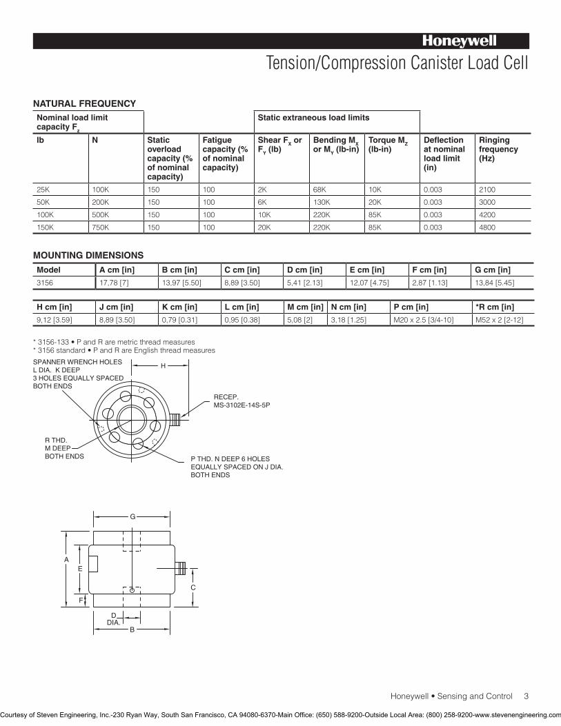
Honeywell•SensingandControl3
Tension/Compression Canister Load Cell
NATURAL FREQUENCYNominal load limit capacity Fz
Static extraneous load limits
lb N Static overload capacity (% of nominal capacity)
Fatigue capacity (% of nominal capacity)
Shear FX or FY (lb)
Bending MX or MY (lb-in)
Torque MZ (lb-in)
Deflection at nominal load limit (in)
Ringing frequency (Hz)
25K 100K 150 100 2K 68K 10K 0.003 2100
50K 200K 150 100 6K 130K 20K 0.003 3000
100K 500K 150 100 10K 220K 85K 0.003 4200
150K 750K 150 100 20K 220K 85K 0.003 4800
Model A cm [in] B cm [in] C cm [in] D cm [in] E cm [in] F cm [in] G cm [in]
3156 17,78[7] 13,97[5.50] 8,89[3.50] 5,41[2.13] 12,07[4.75] 2,87[1.13] 13,84[5.45]
H cm [in] J cm [in] K cm [in] L cm [in] M cm [in] N cm [in] P cm [in] *R cm [in]
9,12[3.59] 8,89[3.50] 0,79[0.31] 0,95[0.38] 5,08[2] 3,18[1.25] M20x2.5[3/4-10] M52x2[2-12]
*3156-133•PandRaremetricthreadmeasures*3156standard•PandRareEnglishthreadmeasures
MOUNTING DIMENSIONS
P THD. N DEEP 6 HOLESEQUALLY SPACED ON J DIA.BOTH ENDS
RECEP.MS-3102E-14S-5P
H
R THD.M DEEPBOTH ENDS
SPANNER WRENCH HOLESL DIA. K DEEP3 HOLES EQUALLY SPACEDBOTH ENDS
G
C
AE
F
DDIA.
B
Courtesy of Steven Engineering, Inc.-230 Ryan Way, South San Francisco, CA 94080-6370-Main Office: (650) 588-9200-Outside Local Area: (800) 258-9200-www.stevenengineering.com

SensingandControl
AutomationandControlSolutions
Honeywell
1985DouglasDriveNorth
GoldenValley,MN55422USA
+1-815-235-6847
www.honeywell.com/sensing
008645-1-EN IL50 GLO May 2008Copyright © 2008 Honeywell International Inc. All rights reserved.
Model 3156 Tension/Compression Canister Load Cell
NOTES
1.ThisunitcalibratedtoImperial(non-Metric)units.
Warranty. Honeywellwarrantsgoodsofitsmanufactureasbeingfreeofdefectivematerialsandfaultyworkmanship.Honeywell’sstandardproductwarrantyappliesunlessagreedtootherwisebyHoneywellinwriting;pleaserefertoyourorderacknowledgementorconsultyourlocalsalesofficeforspecificwarrantydetails.IfwarrantedgoodsarereturnedtoHoneywellduringtheperiodofcoverage,Honeywellwillrepairorreplace,atitsoption,withoutchargethoseitemsitfindsdefective.The foregoing is buyer’s sole remedy and is in lieu of all warranties, expressed or implied, including those of merchantability and fitness for a particular purpose. In no event shall Honeywell be liable for consequential, special, or indirect damages.
Whileweprovideapplicationassistancepersonally,throughourliteratureandtheHoneywellwebsite,itisuptothecustomertodeterminethesuitabilityoftheproductintheapplication.
Specificationsmaychangewithoutnotice.Theinformationwesupplyisbelievedtobeaccurateandreliableasofthisprinting.However,weassumenoresponsibilityforitsuse.
FormoreinformationaboutSensingandControlproducts,visitwww.honeywell.com/sensingorcall+1-815-235-6847Emailinquiriestoinfo.sc@honeywell.com
WARNINGPERSONAL INJURY•DONOTUSEtheseproductsassafetyoremergencystopdevicesorinanyotherapplicationwherefailureoftheproductcouldresultinpersonalinjury.
Failure to comply with these instructions could result in death or serious injury.
WARNINGMISUSE OF DOCUMENTATION•Theinformationpresentedinthiscatalogueisforreferenceonly.DONOTUSEthisdocumentasproductinstallationinformation.•Completeinstallation,operationandmaintenanceinformationisprovidedintheinstructionssuppliedwitheachproduct.
Failure to comply with these instructions could result in death or serious injury.
Courtesy of Steven Engineering, Inc.-230 Ryan Way, South San Francisco, CA 94080-6370-Main Office: (650) 588-9200-Outside Local Area: (800) 258-9200-www.stevenengineering.com
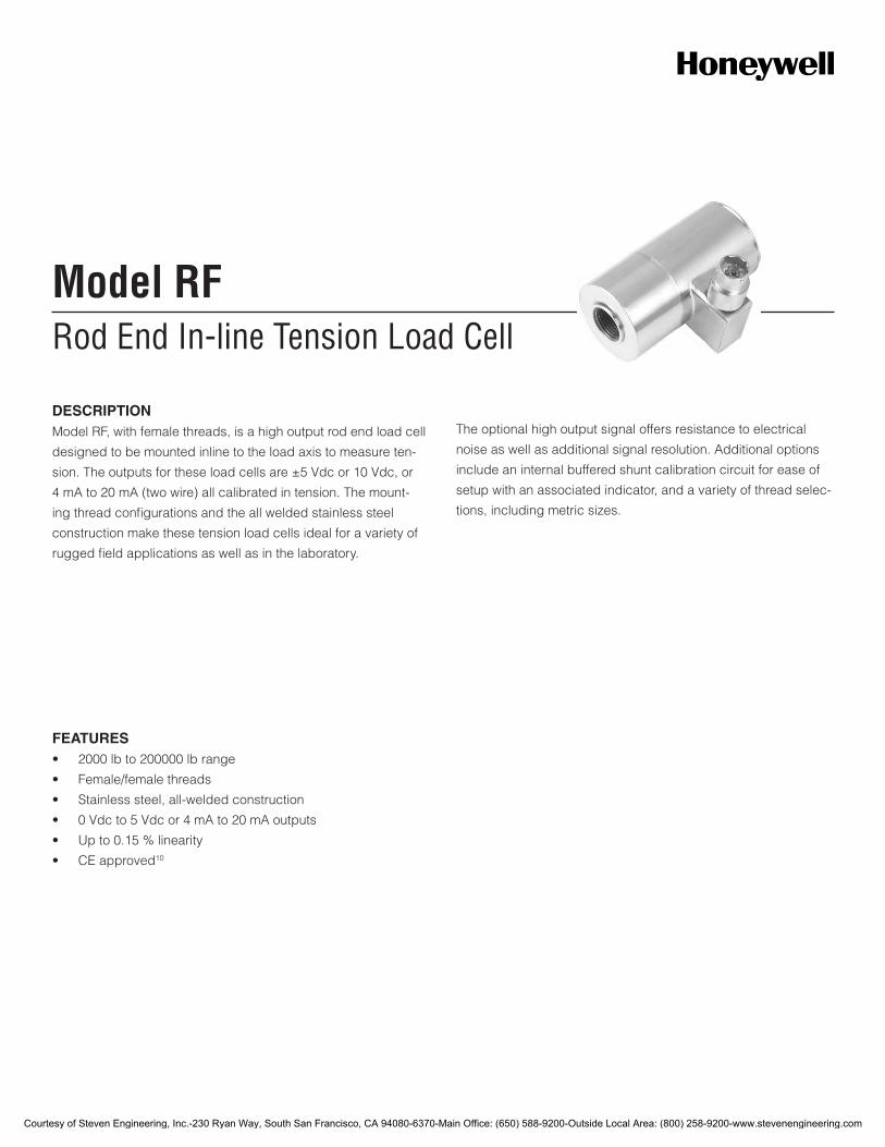
Rod End In-line Tension Load CellModel RF
DESCRIPTIONModel RF, with female threads, is a high output rod end load cell
designed to be mounted inline to the load axis to measure ten-
sion. The outputs for these load cells are ±5 Vdc or 10 Vdc, or
4 mA to 20 mA (two wire) all calibrated in tension. The mount-
ing thread configurations and the all welded stainless steel
construction make these tension load cells ideal for a variety of
rugged field applications as well as in the laboratory.
The optional high output signal offers resistance to electrical
noise as well as additional signal resolution. Additional options
include an internal buffered shunt calibration circuit for ease of
setup with an associated indicator, and a variety of thread selec-
tions, including metric sizes.
FEATURES• 2000lbto200000lbrange
• Female/femalethreads
• Stainlesssteel,all-weldedconstruction
• 0Vdcto5Vdcor4mAto20mAoutputs
• Upto0.15%linearity
• CEapproved10
Courtesy of Steven Engineering, Inc.-230 Ryan Way, South San Francisco, CA 94080-6370-Main Office: (650) 588-9200-Outside Local Area: (800) 258-9200-www.stevenengineering.com

2Honeywell•SensingandControl
Model RFPERFORMANCE SPECIFICATIONS
Characteristic Measure
Load ranges12 2000 lb to 200000 lb
Linearity100 lb to 1000 lb
±0.2%fullscale
Linearity2000 lb to 50000 lb
±0.15%fullscale
Linearity75000 lb to 20000 lb
±0.2%fullscale
Hysteresis100 lb to 1000 lb
±0.2%fullscale
Hysteresis2000 lb to 50000 lb
±0.15%fullscale
Hysteresis75000 lb to 20000 lb
±0.2%fullscale
Non-repeatability ±0.05%fullscale
Output 2mV/V
Operation Tension
Resolution Infinite
ENVIRONMENTAL SPECIFICATIONS
Characteristic Measure
Temperature, operating -54°Cto121°C[-65°Fto250°F]
Temperature, compensated 15°Cto71°C[60°Fto160°F]
Temperature effect, zero 0.005%fullscale/°F
Temperature effect, span 0.005%fullscale/°F
ELECTRICAL SPECIFICATIONS
Characteristic Measure
Straingagetype Bonded foil
Excitation(calibration) 10 Vdc
Excitation(acceptable) Upto15VdcorVac
Insulation resistance 5000 mOhm @ 50 Vdc
Bridge resistance (toler-ance)
350 ohm
Zero balance (tolerance) ±1%fullscale
Shuntcalibrationdata Included
Electricaltermination(std)2000 lb to 50000 lb
PTIH-10-6Porequivalent(hermeticstainless)
Electricaltermination(std)75000 lb to 200000 lb
MS3102E-14S-6Porequivalent
Mating connector (not in-cluded) 2000 lb to 50000 lb
PT06A-10-6Sorequivalent(AA111)
Mating connector (not included) 75000 lb to 200000 lb
MS3106A-14S-6Sorequivalent(AA121)
MECHANICAL SPECIFICATIONS
Characteristic Measure
Maximum allowable load 150%FS1
Weight Seetable
Material Stainlesssteel
Deflection full scale Seetable
Naturalfrequency Seetable
RANGE CODES
Range Code
Available ranges Range Code
Available ranges
DL 2000 lb EL 20000 lb
DN 3000 lb EN 30000 lb
DP 4000 lb EP 50000 lb
DR 5000 lb ER 75000 lb
DT 75000 lb ET 100000 lb
DV 10000 lb FJ 150000 lb
EJ 15000 lb FL 200000 lb
WIRING CODES
Connector Unamplified (Std.)
A (+) excitation
B (+) excitation
C (-) excitation
D (-) excitation
E (-) output
F (+) output
DEFLECTIONS AND RINGING FREQUENCIES
Capacity (lb) Deflection at full scale mm [in]
Ringing fre-quency (Hz)
Weight kg [lb]
2000 0,076[0.003] 5000 0,58[1.3]
3000 0,076[0.003] 5000 0,58[1.3]
4000 0,076[0.003] 5100 0,58[1.3]
5000 0,076[0.003] 5200 0,58[1.3]
7500 0,076[0.003] 8000 0,72[1.6]
10000 0,076[0.003] 8500 0,72[1.6]
15000 0,076[0.003] 9000 0,72[1.6]
20000 0,102[0.004] 9000 0,77[1.7]
30000 0,102[0.004] 8000 1,58[3.5]
50000 0,127[0.005] 8000 1,67[3.7]
75000 to 100000
0,152[0.006] 3500 18,00[39.7]
150000 to 200000
0,178[0.007] 3000 33,02[72.8]
Courtesy of Steven Engineering, Inc.-230 Ryan Way, South San Francisco, CA 94080-6370-Main Office: (650) 588-9200-Outside Local Area: (800) 258-9200-www.stevenengineering.com

Honeywell•SensingandControl3
Rod End In-Line Tension Load CellINTERNAL AMPLIFIERS
Amplifier specifica-tions
Voltage output: Option 2b
Voltage output: Option 2c
Voltage output: Option 2t
Current three-wire: Option 2j
Current two-wire: Option 2k
Intrinsically safe amp: Option 2n (2N)***
Output signal ±5 V 0 V to 5 V or ±5 V @ 45 mA
0 V to 10 V or ±10 V @ 45 mA
4 mA to 20 mA 4 mA to 20 mA 4 mA to 20 mA
Input power (voltage)
±15Vor26Vdcto32 Vdc
11 Vdc to 28 Vdc 15 Vdc to 28 Vdc 22 Vdc to 32 Vdc 15 Vdc to 40 Vdc 9 Vdc to 28 Vdc
Input power (current)
45 mA 40 mA 40 mA 65mA 4 mA to 28 mA 4 mA to 24 mA
Freq. resp (amp)
3000 Hz 3000 Hz 3000 Hz 2500 Hz 300 Hz 2000 Hz
Power supply rej.
60db 60db 60db 60db 60db 60db
Operating temp.
-20 °F to 185 °F -20 °F to 185 °F -20 °F to 185 °F 0 °F to 185 °F 0 °F to 185 °F -20 °F to 185 °F
Reverse voltage protection
Yes Yes Yes Yes Yes Yes
Short cir. protection
Momentary Momentary Momentary Yes Yes Yes
Wiring code: connector (std)5
A(+)SupplyB Output commonCSupplyreturnD (+) OutputEShuntcal1FShuntcal2
A(+)SupplyB Output common**CSupplyreturn**D (+) OutputEShuntcal1FShuntcal2
A(+)SupplyB Output common**CSupplyreturn**D (+) OutputEShuntcal1FShuntcal2
A(+)SupplyB Output common**CSupplyreturn**D (+) OutputEShuntcal1FShuntcal2
A(+)SupplyB No connectionCNoconnectionD (+) OutputECasegroundF No connection
A(+)SupplyB No connectionCNoconnectionD (+) OutputECasegroundF No connection
Wiring code: cable5,6,7
R(+)SupplyBl Output commonGSupplyreturnW (+) OutputBShuntcal1BrShuntcal2
R(+)SupplyBl Output common*GSupplyreturn*W (+) OutputBShuntcal1BrShuntcal2
R(+)SupplyBl Output common*GSupplyreturn*W (+) OutputBShuntcal1BrShuntcal2
R(+)SupplyBl Output common*GSupplyreturn*W (+) OutputBShuntcal1BrShuntcal2
R(+)SupplyBl (+) OutputWCaseground
R(+)SupplyBl (+) OutputWCaseground
* Black and green wires are internally connected.**PinsBandCareinternallyconnected.***SeeourWebsiteforthemostup-to-dateinformationregardingintrinsicallysafeapprovals,ref.#008-0547-00.
Courtesy of Steven Engineering, Inc.-230 Ryan Way, South San Francisco, CA 94080-6370-Main Office: (650) 588-9200-Outside Local Area: (800) 258-9200-www.stevenengineering.com

4Honeywell•SensingandControl
Model RFOPTION CODES
Many range/option combinations are available in our quick-ship and fast-track manufacture programs. Please see http://sensing.honeywell.com/TMsensor-ship for updated listings.
Load ranges 2K, 3K, 4K, 5K, 7.5K, 10K, 15K, 20K, 30K, 50K, 75K, 100K, 150K, 200K
Temperature compensa-tion
1a.60°Fto160°F1b. 30 °F to 130 °F1c. 0 °F to 185 °F1d. -20 °F to 130 °F1e. -20 °F to 200 °F 1f. 70 °F to 250 °F
1g. 70 °F to 325 °F8
1h. 70 °F to 400 °F8
1i.-65°Fto250°F8
1j.0°Cto50°C1k.-20°Cto85°C1m.-25°Cto110°C
Internal amplifiers
2b. 4 wire, ±5 Vdc output2c. 0 Vdc to 5 Vdc2j. 4 mA to 20 mA (three-wire) output2k. 4 mA to 20 mA (two-wire)12
2n (2N) 4 mA to 20 mA (two-wire) intrinsically safe12
2t. 0 Vdc to 10 Vdc output2u.Unamplified,mV/Voutput
Internal amp enhance-ments
3a.Input/outputisolation7
3d. Remote buffered shunt calibration
Electrical termination
6a.BendixPTIH-10-6P(orequivalent)6-pin,(max.250°F)(ranges 50000 lb and below)
6b.MSconnectorMS3102E-14S-6P(mateswithMS3106E-14S-6),(max.160°F)(rangesabove50000lb)6
6e.Integralcable:Teflon6f.Integralcable:PVC
6g.Integralcable:Neoprene6h.Integralcable:Silicone6i.Integralunderwatercable6j.1/2-14conduitfittingwith5ftof4conductorPVCcable6q.Integralcable:Polyurethane6v.Phoenixconnectoronendofcable
Shunt calibration
8a. Precision internal resistor8
Bridge type 11a.Squarebridge8
11b.Symmetricalbridge8 11c.Squareandsymmetricalbridge8 31a. Dual bridge
Bridge resistance
12b. 5000 ohm (foil) (max. 250 °F)
Zero and span adjustment
14a. No access to zero and span adjustment
Electrical connector orientation
15a. Horizontal electrical exit port orientation15b. Vertical electrical exit port orientation15c. Radial electrical exit port orientation15d.Connectoronendofcable
Shock and vibration
44a.Shockandvibrationresistance
Interfaces 53e.Signaturecalibration8
53t.TEDSIEEE1451.4module9
Courtesy of Steven Engineering, Inc.-230 Ryan Way, South San Francisco, CA 94080-6370-Main Office: (650) 588-9200-Outside Local Area: (800) 258-9200-www.stevenengineering.com
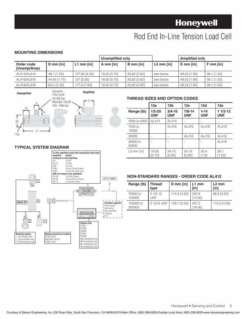
Honeywell•SensingandControl5
Rod End In-Line Tension Load Cell
MOUNTING DIMENSIONS
TYPICAL SYSTEM DIAGRAM
Unamplified only Amplified only
Order code(Unamp/Amp)
D mm [in] L1 mm [in] A mm [in] B mm [in] L2 mm [in] E mm [in] F mm [in]
AL414/AL614 38,1[1.50] 107,95[4.25] 19,05[0.75] 20,82[0.82] see below 49,53[1.95] 38,1[1.50]
AL416/AL616 44,45[1.75] 127[5.00] 19,05[0.75] 20,82[0.82] see below 49,53[1.95] 38,1[1.50]
AL418/AL618 63,5[2.50] 177,8[7.00] 19,05[0.75] 20,82[0.82] see below 49,53[1.95] 38,1[1.50]
THREAD SIZES AND OPTION CODES
13a 13b 13c 13d 13e
Range (lb) 1/2-20 UNF
3/4-16 UNF
7/8-14 UNF
1-14 UNF
1 1/2-12 UNF
2000 to 5000 AL414 AL414 – – –
7500 to 15000
– AL416 AL416 AL416 AL418
20000 – – AL416 AL416 AL418
30000 to 50000
– – – – AL418
L2mm[in] 19,05 [0.75]
24,13 [0.95]
24,13 [0.95]
25,4 [1.0]
38,1 [1.50]
NON-STANDARD RANGES - ORDER CODE AL412
Range (lb) Thread type
D mm [in] L1 mm [in]
L2 mm [in]
75000 to 100000
21/2-12UNF
114,3[4.50] 342,9 [13.50]
88,9[3.50]
150000 to 200000
31/2-8UNF 139,7[5.50] 457,2 [18.00]
114,3[4.50]
Courtesy of Steven Engineering, Inc.-230 Ryan Way, South San Francisco, CA 94080-6370-Main Office: (650) 588-9200-Outside Local Area: (800) 258-9200-www.stevenengineering.com
008656-2-EN IL50 GLO January 2010Copyright © 2010 Honeywell International Inc. All rights reserved.
Model RF Rod End In-Line Tension Load Cell
Sensing and Control
Honeywell
1985 Douglas Drive North
Golden Valley, MN 55422
www.honeywell.com
NOTES
1. Allowable maximum loads – maximum load to be applied without damage.2
2. Without damage - loading to this level will not cause excessive zero shift or performance degradation. The user must consider fatigue life for long term use and structural integrity. All structurally critical applications (overhead loading, etc.) should always be designed with safety redundant load paths.
3. Interconnecting shunt cal. 1 terminal with shunt cal. 2 terminal provides50%(unamplifiedunits),75%(4mAto20mAthree-wireunits)or80%(voltageamplifiedunits)offullscaleoutputforquickcalibration.Shuntcalibrationcomesstandardwithinternalampli-fier option 2a, 2b, 2c, 2t and 2j.
4. O=Orange; Y=Yellow; B=Blue; Bl=Black; R=Red; Br=Brown; W=White;G=Green.Colorspecifyingcableandnumberorletterspecifying connector.
5. No mating connector necessary for cable option.6. Cannotbeusedwithoptions1c,1e,1f,1g,1h,or1i.7. Only available with option 2b or 2c.8. Not available with amplified option.9. ConsultfactoryforTEDSavailabilitywithamplifiedmodels.10. Termination dependent; consult factory.11. This unit calibrated to Imperial (non-Metric) units.12. 5000ohmbridgerequired.
Find out more
Honeywell serves its customers
through a worldwide network of
sales offices, representatives
and distributors. For application
assistance, current specifica-
tions, pricing or name of the
nearest Authorized Distributor,
contact your local sales office.
To learn more about Honeywell’s
test and measurement products,
call +1-614-850-5000, visit
www.honeywell.com/sensotec,
ore-mailinquiriesto
Warranty. Honeywell warrants goods of its manufacture as being free of defective materials and faulty workmanship. Honeywell’s standard product warranty applies unless agreed to otherwise by Honeywell in writing; please refer to your order acknowledgement or consult your local sales office for specific warranty details. If warranted goods are returned to Honeywell during the period of coverage, Honeywell will repair or replace, at its option, without charge those items it finds defective. The foregoing is buyer’s sole remedy and is in lieu of all warranties, expressed or implied, including those of merchantability and fitness for a particular purpose. In no event shall Honeywell be liable for consequential, special, or indirect damages.
While we provide application assistance personally, through our literature and the Honeywell web site, it is up to the customer to determine the suitability of the product in the application.
Specificationsmaychangewithoutnotice.Theinformationwesupply is believed to be accurate and reliable as of this printing. However, we assume no responsibility for its use.
WARNINGPERSONAL INJURY
•DONOTUSEtheseproductsassafetyoremergencystop devices or in any other application where failure of the product could result in personal injury.
Failure to comply with these instructions could result in death or serious injury.
WARNINGMISUSE OF DOCUMENTATION
•Theinformationpresentedinthisdatasheetisforreferenceonly.DONOTUSEthisdocumentasproductinstallation information.
•Completeinstallation,operationandmaintenanceinformation is provided in the instructions supplied with each product.
Failure to comply with these instructions could result in death or serious injury.
Courtesy of Steven Engineering, Inc.-230 Ryan Way, South San Francisco, CA 94080-6370-Main Office: (650) 588-9200-Outside Local Area: (800) 258-9200-www.stevenengineering.com
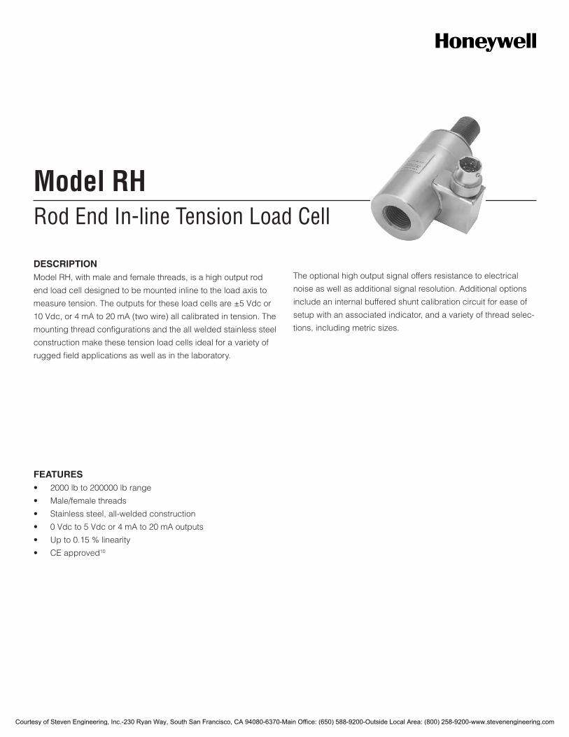
Rod End In-line Tension Load CellModel RH
DESCRIPTIONModel RH, with male and female threads, is a high output rod
end load cell designed to be mounted inline to the load axis to
measure tension. The outputs for these load cells are ±5 Vdc or
10 Vdc, or 4 mA to 20 mA (two wire) all calibrated in tension. The
mounting thread configurations and the all welded stainless steel
construction make these tension load cells ideal for a variety of
rugged field applications as well as in the laboratory.
The optional high output signal offers resistance to electrical
noise as well as additional signal resolution. Additional options
include an internal buffered shunt calibration circuit for ease of
setup with an associated indicator, and a variety of thread selec-
tions, including metric sizes.
FEATURES• 2000lbto200000lbrange
• Male/femalethreads
• Stainlesssteel,all-weldedconstruction
• 0Vdcto5Vdcor4mAto20mAoutputs
• Upto0.15%linearity
• CEapproved10
Courtesy of Steven Engineering, Inc.-230 Ryan Way, South San Francisco, CA 94080-6370-Main Office: (650) 588-9200-Outside Local Area: (800) 258-9200-www.stevenengineering.com
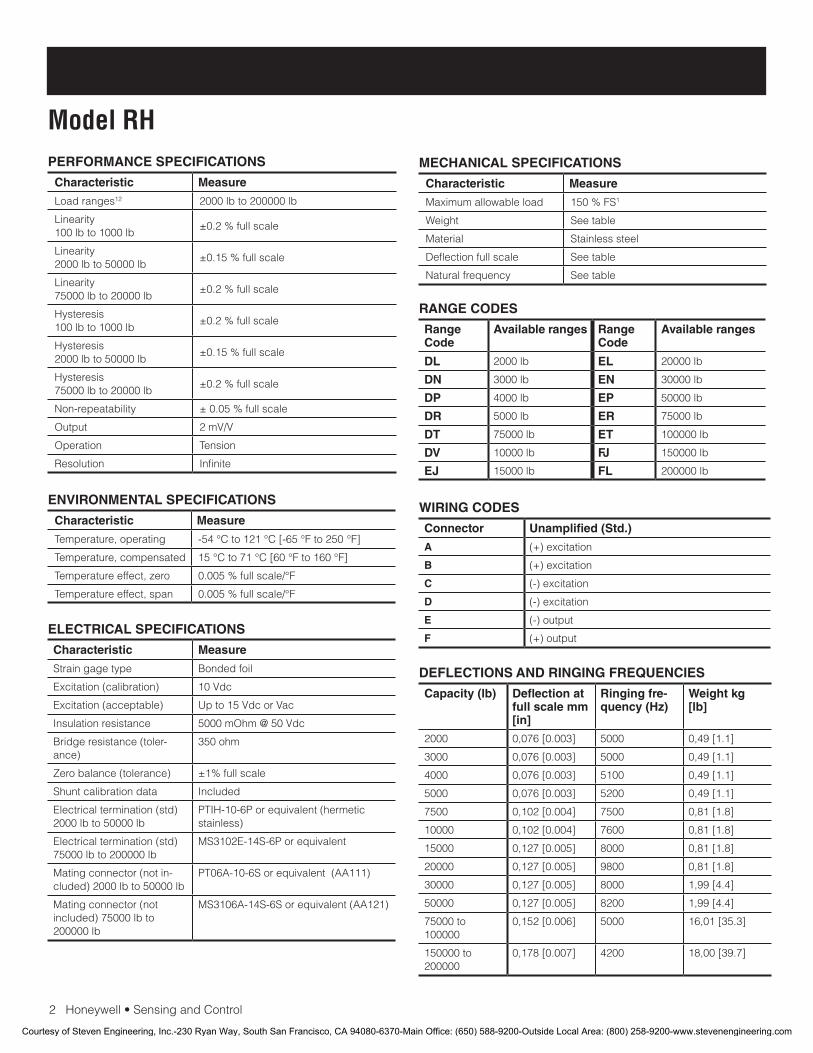
2Honeywell•SensingandControl
Model RHPERFORMANCE SPECIFICATIONS
Characteristic Measure
Load ranges12 2000 lb to 200000 lb
Linearity100 lb to 1000 lb
±0.2%fullscale
Linearity2000 lb to 50000 lb
±0.15%fullscale
Linearity75000 lb to 20000 lb
±0.2%fullscale
Hysteresis100 lb to 1000 lb
±0.2%fullscale
Hysteresis2000 lb to 50000 lb
±0.15%fullscale
Hysteresis75000 lb to 20000 lb
±0.2%fullscale
Non-repeatability ±0.05%fullscale
Output 2mV/V
Operation Tension
Resolution Infinite
ENVIRONMENTAL SPECIFICATIONS
Characteristic Measure
Temperature, operating -54°Cto121°C[-65°Fto250°F]
Temperature, compensated 15°Cto71°C[60°Fto160°F]
Temperature effect, zero 0.005%fullscale/°F
Temperature effect, span 0.005%fullscale/°F
ELECTRICAL SPECIFICATIONS
Characteristic Measure
Straingagetype Bonded foil
Excitation(calibration) 10 Vdc
Excitation(acceptable) Upto15VdcorVac
Insulation resistance 5000 mOhm @ 50 Vdc
Bridge resistance (toler-ance)
350 ohm
Zero balance (tolerance) ±1%fullscale
Shuntcalibrationdata Included
Electricaltermination(std)2000 lb to 50000 lb
PTIH-10-6Porequivalent(hermeticstainless)
Electricaltermination(std)75000 lb to 200000 lb
MS3102E-14S-6Porequivalent
Mating connector (not in-cluded) 2000 lb to 50000 lb
PT06A-10-6Sorequivalent(AA111)
Mating connector (not included) 75000 lb to 200000 lb
MS3106A-14S-6Sorequivalent(AA121)
MECHANICAL SPECIFICATIONS
Characteristic Measure
Maximum allowable load 150%FS1
Weight Seetable
Material Stainlesssteel
Deflection full scale Seetable
Naturalfrequency Seetable
RANGE CODES
Range Code
Available ranges Range Code
Available ranges
DL 2000 lb EL 20000 lb
DN 3000 lb EN 30000 lb
DP 4000 lb EP 50000 lb
DR 5000 lb ER 75000 lb
DT 75000 lb ET 100000 lb
DV 10000 lb FJ 150000 lb
EJ 15000 lb FL 200000 lb
WIRING CODES
Connector Unamplified (Std.)
A (+) excitation
B (+) excitation
C (-) excitation
D (-) excitation
E (-) output
F (+) output
DEFLECTIONS AND RINGING FREQUENCIES
Capacity (lb) Deflection at full scale mm [in]
Ringing fre-quency (Hz)
Weight kg [lb]
2000 0,076[0.003] 5000 0,49[1.1]
3000 0,076[0.003] 5000 0,49[1.1]
4000 0,076[0.003] 5100 0,49[1.1]
5000 0,076[0.003] 5200 0,49[1.1]
7500 0,102[0.004] 7500 0,81[1.8]
10000 0,102[0.004] 7600 0,81[1.8]
15000 0,127[0.005] 8000 0,81[1.8]
20000 0,127[0.005] 9800 0,81[1.8]
30000 0,127[0.005] 8000 1,99[4.4]
50000 0,127[0.005] 8200 1,99[4.4]
75000 to 100000
0,152[0.006] 5000 16,01[35.3]
150000 to 200000
0,178[0.007] 4200 18,00[39.7]
Courtesy of Steven Engineering, Inc.-230 Ryan Way, South San Francisco, CA 94080-6370-Main Office: (650) 588-9200-Outside Local Area: (800) 258-9200-www.stevenengineering.com
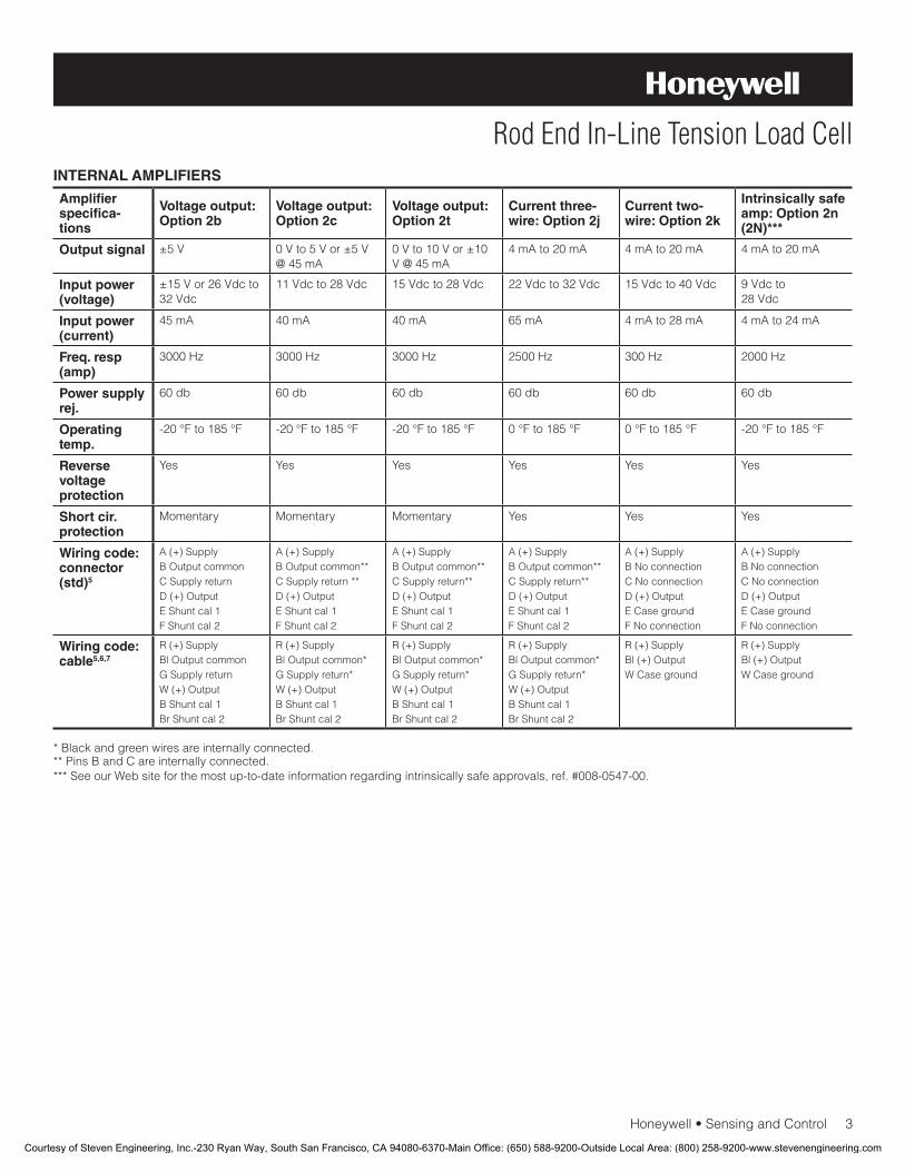
Honeywell•SensingandControl3
Rod End In-Line Tension Load CellINTERNAL AMPLIFIERS
Amplifier specifica-tions
Voltage output: Option 2b
Voltage output: Option 2c
Voltage output: Option 2t
Current three-wire: Option 2j
Current two-wire: Option 2k
Intrinsically safe amp: Option 2n (2N)***
Output signal ±5 V 0 V to 5 V or ±5 V @ 45 mA
0 V to 10 V or ±10 V @ 45 mA
4 mA to 20 mA 4 mA to 20 mA 4 mA to 20 mA
Input power (voltage)
±15Vor26Vdcto32 Vdc
11 Vdc to 28 Vdc 15 Vdc to 28 Vdc 22 Vdc to 32 Vdc 15 Vdc to 40 Vdc 9 Vdc to 28 Vdc
Input power (current)
45 mA 40 mA 40 mA 65mA 4 mA to 28 mA 4 mA to 24 mA
Freq. resp (amp)
3000 Hz 3000 Hz 3000 Hz 2500 Hz 300 Hz 2000 Hz
Power supply rej.
60db 60db 60db 60db 60db 60db
Operating temp.
-20°Fto185°F -20°Fto185°F -20°Fto185°F 0°Fto185°F 0°Fto185°F -20°Fto185°F
Reverse voltage protection
Yes Yes Yes Yes Yes Yes
Short cir. protection
Momentary Momentary Momentary Yes Yes Yes
Wiring code: connector (std)5
A(+)SupplyB Output commonCSupplyreturnD (+) OutputEShuntcal1FShuntcal2
A(+)SupplyB Output common**CSupplyreturn**D (+) OutputEShuntcal1FShuntcal2
A(+)SupplyB Output common**CSupplyreturn**D (+) OutputEShuntcal1FShuntcal2
A(+)SupplyB Output common**CSupplyreturn**D (+) OutputEShuntcal1FShuntcal2
A(+)SupplyB No connectionCNoconnectionD (+) OutputECasegroundFNoconnection
A(+)SupplyB No connectionCNoconnectionD (+) OutputECasegroundFNoconnection
Wiring code: cable5,6,7
R(+)SupplyBl Output commonGSupplyreturnW (+) OutputBShuntcal1BrShuntcal2
R(+)SupplyBl Output common*GSupplyreturn*W (+) OutputBShuntcal1BrShuntcal2
R(+)SupplyBl Output common*GSupplyreturn*W (+) OutputBShuntcal1BrShuntcal2
R(+)SupplyBl Output common*GSupplyreturn*W (+) OutputBShuntcal1BrShuntcal2
R(+)SupplyBl (+) OutputWCaseground
R(+)SupplyBl (+) OutputWCaseground
* Black and green wires are internally connected.**PinsBandCareinternallyconnected.***SeeourWebsiteforthemostup-to-dateinformationregardingintrinsicallysafeapprovals,ref.#008-0547-00.
Courtesy of Steven Engineering, Inc.-230 Ryan Way, South San Francisco, CA 94080-6370-Main Office: (650) 588-9200-Outside Local Area: (800) 258-9200-www.stevenengineering.com
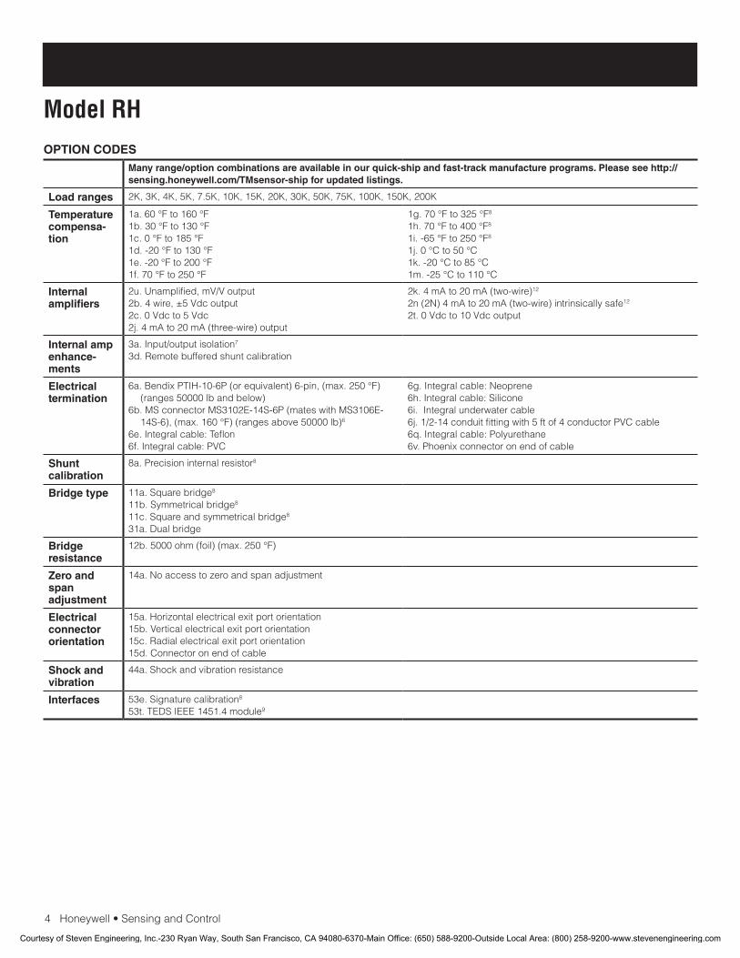
4Honeywell•SensingandControl
Model RHOPTION CODES
Many range/option combinations are available in our quick-ship and fast-track manufacture programs. Please see http://sensing.honeywell.com/TMsensor-ship for updated listings.
Load ranges 2K, 3K, 4K, 5K, 7.5K, 10K, 15K, 20K, 30K, 50K, 75K, 100K, 150K, 200K
Temperature compensa-tion
1a.60°Fto160°F1b.30°Fto130°F1c.0°Fto185°F1d.-20°Fto130°F1e.-20°Fto200°F1f.70°Fto250°F
1g.70°Fto325°F8
1h.70°Fto400°F8
1i.-65°Fto250°F8
1j.0°Cto50°C1k.-20°Cto85°C1m.-25°Cto110°C
Internal amplifiers
2u.Unamplified,mV/Voutput2b. 4 wire, ±5 Vdc output2c. 0 Vdc to 5 Vdc2j. 4 mA to 20 mA (three-wire) output
2k. 4 mA to 20 mA (two-wire)12
2n (2N) 4 mA to 20 mA (two-wire) intrinsically safe12
2t. 0 Vdc to 10 Vdc output
Internal amp enhance-ments
3a.Input/outputisolation7
3d. Remote buffered shunt calibration
Electrical termination
6a.BendixPTIH-10-6P(orequivalent)6-pin,(max.250°F)(ranges 50000 lb and below)
6b.MSconnectorMS3102E-14S-6P(mateswithMS3106E-14S-6),(max.160°F)(rangesabove50000lb)6
6e.Integralcable:Teflon6f.Integralcable:PVC
6g.Integralcable:Neoprene6h.Integralcable:Silicone6i.Integralunderwatercable6j.1/2-14conduitfittingwith5ftof4conductorPVCcable6q.Integralcable:Polyurethane6v.Phoenixconnectoronendofcable
Shunt calibration
8a. Precision internal resistor8
Bridge type 11a.Squarebridge8
11b.Symmetricalbridge8 11c.Squareandsymmetricalbridge8 31a. Dual bridge
Bridge resistance
12b.5000ohm(foil)(max.250°F)
Zero and span adjustment
14a. No access to zero and span adjustment
Electrical connector orientation
15a. Horizontal electrical exit port orientation15b. Vertical electrical exit port orientation15c. Radial electrical exit port orientation15d.Connectoronendofcable
Shock and vibration
44a.Shockandvibrationresistance
Interfaces 53e.Signaturecalibration8
53t.TEDSIEEE1451.4module9
Courtesy of Steven Engineering, Inc.-230 Ryan Way, South San Francisco, CA 94080-6370-Main Office: (650) 588-9200-Outside Local Area: (800) 258-9200-www.stevenengineering.com
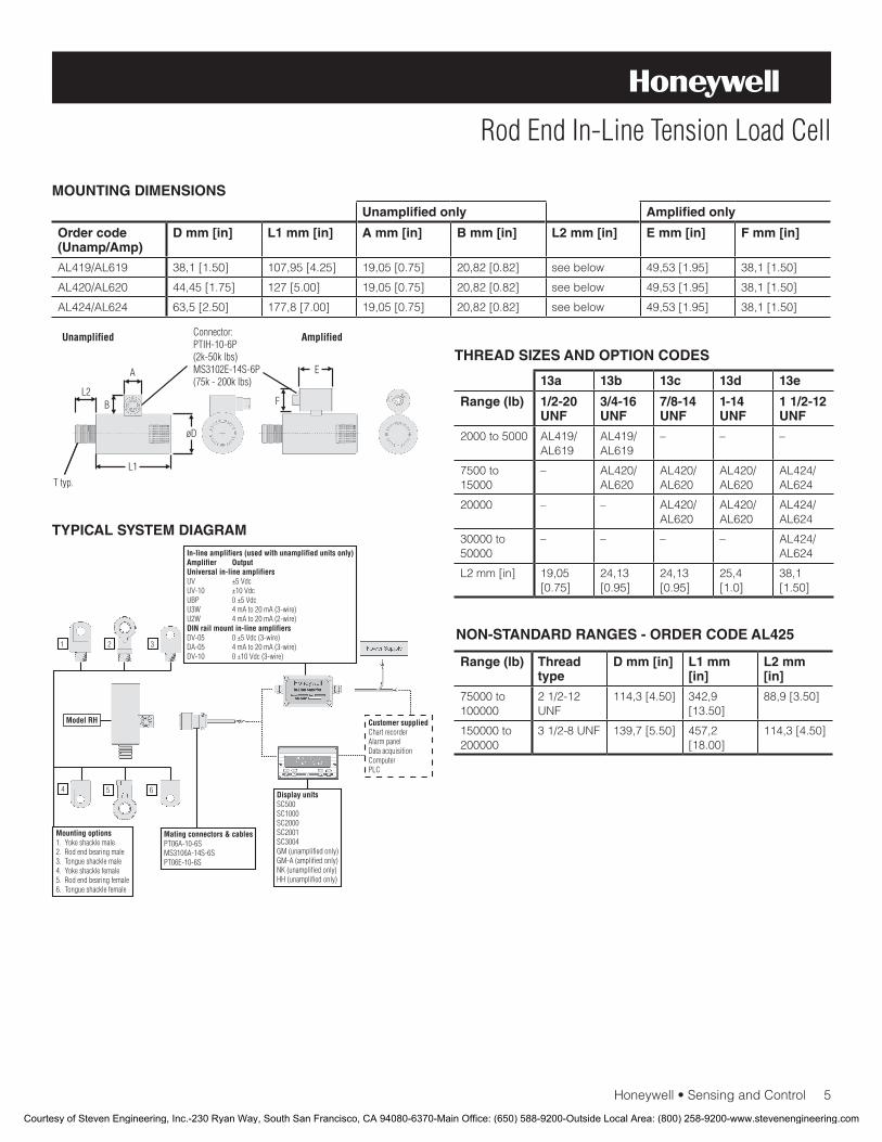
Honeywell•SensingandControl5
Rod End In-Line Tension Load Cell
MOUNTING DIMENSIONS
TYPICAL SYSTEM DIAGRAM
Unamplified only Amplified only
Order code(Unamp/Amp)
D mm [in] L1 mm [in] A mm [in] B mm [in] L2 mm [in] E mm [in] F mm [in]
AL419/AL619 38,1[1.50] 107,95[4.25] 19,05[0.75] 20,82[0.82] see below 49,53[1.95] 38,1[1.50]
AL420/AL620 44,45[1.75] 127[5.00] 19,05[0.75] 20,82[0.82] see below 49,53[1.95] 38,1[1.50]
AL424/AL624 63,5[2.50] 177,8[7.00] 19,05[0.75] 20,82[0.82] see below 49,53[1.95] 38,1[1.50]
THREAD SIZES AND OPTION CODES
13a 13b 13c 13d 13e
Range (lb) 1/2-20 UNF
3/4-16 UNF
7/8-14 UNF
1-14 UNF
1 1/2-12 UNF
2000 to 5000 AL419/AL619
AL419/AL619
– – –
7500 to 15000
– AL420/AL620
AL420/AL620
AL420/AL620
AL424/AL624
20000 – – AL420/AL620
AL420/AL620
AL424/AL624
30000 to 50000
– – – – AL424/AL624
L2mm[in] 19,05 [0.75]
24,13 [0.95]
24,13 [0.95]
25,4 [1.0]
38,1 [1.50]
NON-STANDARD RANGES - ORDER CODE AL425
Range (lb) Thread type
D mm [in] L1 mm [in]
L2 mm [in]
75000 to 100000
21/2-12UNF
114,3[4.50] 342,9 [13.50]
88,9[3.50]
150000 to 200000
31/2-8UNF 139,7[5.50] 457,2 [18.00]
114,3[4.50]
Courtesy of Steven Engineering, Inc.-230 Ryan Way, South San Francisco, CA 94080-6370-Main Office: (650) 588-9200-Outside Local Area: (800) 258-9200-www.stevenengineering.com
008655-2-EN IL50 GLO January 2010Copyright © 2010 Honeywell International Inc. All rights reserved.
Model RH Rod End In-Line Tension Load Cell
Sensing and Control
Honeywell
1985 Douglas Drive North
Golden Valley, MN 55422
www.honeywell.com
NOTES
1. Allowable maximum loads – maximum load to be applied without damage.2
2. Without damage - loading to this level will not cause excessive zero shift or performance degradation. The user must consider fatigue life for long term use and structural integrity. All structurally critical applications (overhead loading, etc.) should always be designed with safety redundant load paths.
3. Interconnecting shunt cal. 1 terminal with shunt cal. 2 terminal provides50%(unamplifiedunits),75%(4mAto20mAthree-wireunits)or80%(voltageamplifiedunits)offullscaleoutputforquickcalibration.Shuntcalibrationcomesstandardwithinternalampli-fier option 2a, 2b, 2c, 2t and 2j.
4. O=Orange; Y=Yellow; B=Blue; Bl=Black; R=Red; Br=Brown; W=White;G=Green.Colorspecifyingcableandnumberorletterspecifying connector.
5. No mating connector necessary for cable option.6. Cannotbeusedwithoptions1c,1e,1f,1g,1h,or1i.7. Only available with option 2b or 2c.8. Not available with amplified option.9. ConsultfactoryforTEDSavailabilitywithamplifiedmodels.10. Range dependent; consult factory. Termination dependent; consult
factory.11. Internal amp and termination dependent; consult factory.12. This unit calibrated to Imperial (non-Metric) units.13. 5000ohmbridgerequired.
Warranty. Honeywell warrants goods of its manufacture as being free of defective materials and faulty workmanship. Honeywell’s standard product warranty applies unless agreed to otherwise by Honeywell in writing; please refer to your order acknowledgement or consult your local sales office for specific warranty details. If warranted goods are returned to Honeywell during the period of coverage, Honeywell will repair or replace, at its option, without charge those items it finds defective. The foregoing is buyer’s sole remedy and is in lieu of all warranties, expressed or implied, including those of merchantability and fitness for a particular purpose. In no event shall Honeywell be liable for consequential, special, or indirect damages.
While we provide application assistance personally, through our literature and the Honeywell web site, it is up to the customer to determine the suitability of the product in the application.
Specificationsmaychangewithoutnotice.Theinformationwesupply is believed to be accurate and reliable as of this printing. However, we assume no responsibility for its use.
WARNINGPERSONAL INJURY
•DONOTUSEtheseproductsassafetyoremergencystop devices or in any other application where failure of the product could result in personal injury.
Failure to comply with these instructions could result in death or serious injury.
WARNINGMISUSE OF DOCUMENTATION
•Theinformationpresentedinthisdatasheetisforreferenceonly.DONOTUSEthisdocumentasproductinstallation information.
•Completeinstallation,operationandmaintenanceinformation is provided in the instructions supplied with each product.
Failure to comply with these instructions could result in death or serious injury.
Find out more
Honeywell serves its customers
through a worldwide network of
sales offices, representatives
anddistributors.Forapplication
assistance, current specifica-
tions, pricing or name of the
nearest Authorized Distributor,
contact your local sales office.
To learn more about Honeywell’s
test and measurement products,
call +1-614-850-5000, visit
www.honeywell.com/sensotec,
ore-mailinquiriesto
Courtesy of Steven Engineering, Inc.-230 Ryan Way, South San Francisco, CA 94080-6370-Main Office: (650) 588-9200-Outside Local Area: (800) 258-9200-www.stevenengineering.com

Rod End In-line Tension Load CellModel RM
DESCRIPTIONModel RM, with male threads, is a high output rod end load cell
designed to be mounted inline to the load axis to measure ten-
sion. The outputs for these load cells are ±5 Vdc or 10 Vdc, or
4 mA to 20 mA (two wire) all calibrated in tension. The mount-
ing thread configurations and the all welded stainless steel
construction make these tension load cells ideal for a variety of
rugged field applications as well as in the laboratory.
The optional high output signal offers resistance to electrical
noise as well as additional signal resolution. Additional options
include an internal buffered shunt calibration circuit for ease of
setup with an associated indicator, and a variety of thread selec-
tions, including metric sizes.
FEATURES• 2000lbto200000lbrange
• Male/malethreads
• Stainlesssteel,all-weldedconstruction
• 0Vdcto5Vdcor4mAto20mAoutputs
• Upto0.15%linearity
• CEapproved10
Courtesy of Steven Engineering, Inc.-230 Ryan Way, South San Francisco, CA 94080-6370-Main Office: (650) 588-9200-Outside Local Area: (800) 258-9200-www.stevenengineering.com

2Honeywell•SensingandControl
Model RMPERFORMANCE SPECIFICATIONS
Characteristic Measure
Load ranges11 2000 lb to 200000 lb1
Linearity100 lb to 1000 lb
±0.2%fullscale
Linearity2000 lb to 50000 lb
±0.15%fullscale
Linearity75000 lb to 20000 lb
±0.2%fullscale
Hysteresis100 lb to 1000 lb
±0.2%fullscale
Hysteresis2000 lb to 50000 lb
±0.15%fullscale
Hysteresis75000 lb to 20000 lb
±0.2%fullscale
Non-repeatability ±0.05%fullscale
Output (tolerance) 2mV/V
Operation Tension
Resolution Infinite
ENVIRONMENTAL SPECIFICATIONS
Characteristic Measure
Temperature, operating -54°Cto121°C[-65°Fto250°F]
Temperature, compensated 15°Cto71°C[60°Fto160°F]
Temperature effect, zero 0.005%fullscale/°F
Temperature effect, span 0.005%fullscale/°F
ELECTRICAL SPECIFICATIONS
Characteristic Measure
Straingagetype Bonded foil
Excitation(calibration) 10 Vdc
Excitation(acceptable) Upto15VdcorVac
Insulation resistance 5000 mOhm @ 50 Vdc
Bridge resistance (toler-ance)
350 ohm
Zero balance (tolerance) ±1%fullscale
Shuntcalibrationdata Included
Electricaltermination(std)2000 lb to 50000 lb
PTIH-10-6Porequivalent(hermeticstainless)
Electricaltermination(std)75000 lb to 200000 lb
MS3102E-14S-6Porequivalent
Mating connector (not in-cluded) 2000 lb to 50000 lb
PT06A-10-6Sorequivalent(AA111)
Mating connector (not included) 75000 lb to 200000 lb
MS3106A-14S-6Sorequivalent(AA121)
MECHANICAL SPECIFICATIONS
Characteristic Measure
Maximum allowable load 150%FS1
Weight Seetable
Material Stainlesssteel
Deflection full scale Seetable
Naturalfrequency Seetable
RANGE CODES
Range Code
Available ranges Range Code
Available ranges
DL 2000 lb EL 20000 lb
DN 3000 lb EN 30000 lb
DP 4000 lb EP 50000 lb
DR 5000 lb ER 75000 lb
DT 75000 lb ET 100000 lb
DV 10000 lb FJ 150000 lb
EJ 15000 lb FL 200000 lb
WIRING CODES
Connector Unamplified (Std.)
A (+) excitation
B (+) excitation
C (-) excitation
D (-) excitation
E (-) output
F (+) output
DEFLECTIONS AND RINGING FREQUENCIES
Capacity (lb) Deflection at full scale mm [in]
Ringing fre-quency (Hz)
Weight kg [lb]
2000 0,076[0.003] 5000 0,45[1.0]
3000 0,076[0.003] 5000 0,45[1.0]
4000 0,076[0.003] 5100 0,45[1.0]
5000 0,076[0.003] 5200 0,45[1.0]
7500 0,102[0.004] 7500 0,68[1.5]
10000 0,102[0.004] 7600 0,68[1.5]
15000 0,127[0.005] 8000 0,68[1.5]
20000 0,127[0.005] 9800 0,68[1.5]
30000 0,127[0.005] 8000 1,90[4.2]
50000 0,127[0.005] 8200 1,90[4.2]
75000 to 100000
0,152[0.006] 5000 7,34[16.5]
150000 to 200000
0,178[0.007] 4200 16,01[35.3]
Courtesy of Steven Engineering, Inc.-230 Ryan Way, South San Francisco, CA 94080-6370-Main Office: (650) 588-9200-Outside Local Area: (800) 258-9200-www.stevenengineering.com
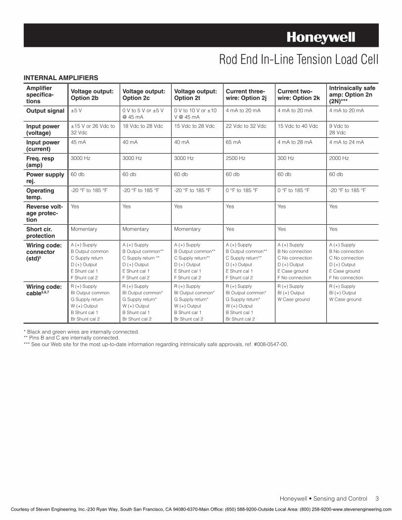
Honeywell•SensingandControl3
Rod End In-Line Tension Load CellINTERNAL AMPLIFIERS
Amplifier specifica-tions
Voltage output: Option 2b
Voltage output: Option 2c
Voltage output: Option 2t
Current three-wire: Option 2j
Current two-wire: Option 2k
Intrinsically safe amp: Option 2n (2N)***
Output signal ±5 V 0 V to 5 V or ±5 V @ 45 mA
0 V to 10 V or ±10 V @ 45 mA
4 mA to 20 mA 4 mA to 20 mA 4 mA to 20 mA
Input power (voltage)
±15Vor26Vdcto32 Vdc
18Vdcto28Vdc 15Vdcto28Vdc 22 Vdc to 32 Vdc 15 Vdc to 40 Vdc 9 Vdc to 28Vdc
Input power (current)
45 mA 40 mA 40 mA 65mA 4mAto28mA 4 mA to 24 mA
Freq. resp (amp)
3000 Hz 3000 Hz 3000 Hz 2500 Hz 300 Hz 2000 Hz
Power supply rej.
60db 60db 60db 60db 60db 60db
Operating temp.
-20°Fto185°F -20°Fto185°F -20°Fto185°F 0°Fto185°F 0°Fto185°F -20°Fto185°F
Reverse volt-age protec-tion
Yes Yes Yes Yes Yes Yes
Short cir. protection
Momentary Momentary Momentary Yes Yes Yes
Wiring code: connector (std)5
A(+)SupplyB Output commonCSupplyreturnD (+) OutputEShuntcal1FShuntcal2
A(+)SupplyB Output common**CSupplyreturn**D (+) OutputEShuntcal1FShuntcal2
A(+)SupplyB Output common**CSupplyreturn**D (+) OutputEShuntcal1FShuntcal2
A(+)SupplyB Output common**CSupplyreturn**D (+) OutputEShuntcal1FShuntcal2
A(+)SupplyB No connectionCNoconnectionD (+) OutputECasegroundFNoconnection
A(+)SupplyB No connectionCNoconnectionD (+) OutputECasegroundFNoconnection
Wiring code: cable5,6,7
R(+)SupplyBl Output commonGSupplyreturnW (+) OutputBShuntcal1BrShuntcal2
R(+)SupplyBl Output common*GSupplyreturn*W (+) OutputBShuntcal1BrShuntcal2
R(+)SupplyBl Output common*GSupplyreturn*W (+) OutputBShuntcal1BrShuntcal2
R(+)SupplyBl Output common*GSupplyreturn*W (+) OutputBShuntcal1BrShuntcal2
R(+)SupplyBl (+) OutputWCaseground
R(+)SupplyBl (+) OutputWCaseground
* Black and green wires are internally connected.**PinsBandCareinternallyconnected.***SeeourWebsiteforthemostup-to-dateinformationregardingintrinsicallysafeapprovals,ref.#008-0547-00.
Courtesy of Steven Engineering, Inc.-230 Ryan Way, South San Francisco, CA 94080-6370-Main Office: (650) 588-9200-Outside Local Area: (800) 258-9200-www.stevenengineering.com

4Honeywell•SensingandControl
Model RMOPTION CODES
Many range/option combinations are available in our quick-ship and fast-track manufacture programs. Please see http://sensing.honeywell.com/TMsensor-ship for updated listings.
Load ranges 2K, 3K, 4K, 5K, 7.5K, 10K, 15K, 20K, 30K, 50K, 75K, 100K, 150K, 200K
Temperature compensa-tion
1a.60°Fto160°F1b.30°Fto130°F1c.0°Fto185°F1d.-20°Fto130°F1e.-20°Fto200°F1f.70°Fto250°F
1g.70°Fto325°F8
1h.70°Fto400°F8
1i.-65°Fto250°F8
1j.0°Cto50°C1k.-20°Cto85°C1m.-25°Cto110°C
Internal amplifiers
2u.Unamplified,mV/Voutput2b. 4 wire, ±5 Vdc output2c. 0 Vdc to 5 Vdc2j. 4 mA to 20 mA (three-wire) output
2k. 4 mA to 20 mA (two-wire)12
2n (2N) 4 mA to 20 mA (two-wire) intrinsically safe12
2t. 0 Vdc to 10 Vdc output
Internal amp enhance-ments
3a.Input/outputisolation7
3d. Remote buffered shunt calibration
Electrical termination
6a.BendixPTIH-10-6P(orequivalent)6-pin,(max.250°F)(ranges 50000 lb and below)
6b.MSconnectorMS3102E-14S-6P(mateswithMS3106E-14S-6),(max.160°F)(rangesabove50000lb)6
6e.Integralcable:Teflon6f.Integralcable:PVC
6g.Integralcable:Neoprene6h.Integralcable:Silicone6i.Integralunderwatercable6j.1/2-14conduitfittingwith5ftof4conductorPVCcable6q.Integralcable:Polyurethane6v.Phoenixconnectoronendofcable
Shunt calibration
8a.Precisioninternalresistor8
Bridge type 11a.Squarebridge8
11b.Symmetricalbridge8 11c.Squareandsymmetricalbridge8 31a. Dual bridge
Bridge resistance
12b.5000ohm(foil)(max.250°F)
Zero and span adjustment
14a. No access to zero and span adjustment
Electrical connector orientation
15a. Horizontal electrical exit port orientation15b. Vertical electrical exit port orientation15c. Radial electrical exit port orientation15d.Connectoronendofcable
Shock and vibration
44a.Shockandvibrationresistance
Interfaces 53e.Signaturecalibration8
53t.TEDSIEEE1451.4module9
Courtesy of Steven Engineering, Inc.-230 Ryan Way, South San Francisco, CA 94080-6370-Main Office: (650) 588-9200-Outside Local Area: (800) 258-9200-www.stevenengineering.com
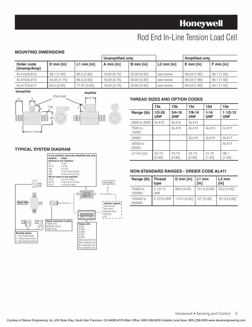
Honeywell•SensingandControl5
Rod End In-Line Tension Load Cell
MOUNTING DIMENSIONS
TYPICAL SYSTEM DIAGRAM
Unamplified only Amplified only
Order code(Unamp/Amp)
D mm [in] L1 mm [in] A mm [in] B mm [in] L2 mm [in] E mm [in] F mm [in]
AL413/AL613 38,1[1.50] 66,4[2.60] 19,05[0.75] 20,82[0.82] see below 49,53[1.95] 38,1[1.50]
AL415/AL615 44,45[1.75] 66,4[2.60] 19,05[0.75] 20,82[0.82] see below 49,53[1.95] 38,1[1.50]
AL417/AL617 63,5[2.50] 77,47[3.05] 19,05[0.75] 20,82[0.82] see below 49,53[1.95] 38,1[1.50]
THREAD SIZES AND OPTION CODES
13a 13b 13c 13d 13e
Range (lb) 1/2-20 UNF
3/4-16 UNF
7/8-14 UNF
1-14 UNF
1 1/2-12 UNF
2000 to 5000 AL413 AL413 AL413
7500 to 15000
AL415 AL415 AL415 AL417
20000 AL415 AL415 AL417
30000 to 50000
AL417
L2mm[in] 24,13 [0.95]
24,13 [0.95]
24,13 [0.95]
31,75 [1.25]
38,1[1.50]
NON-STANDARD RANGES - ORDER CODE AL411
Range (lb) Thread type
D mm [in] L1 mm [in]
L2 mm [in]
75000 to 100000
21/2-12UNF
88,9[3.50] 101,6[4.00] 76,2[3.00]
150000 to 200000
31/2-8UNF 114,3[4.50] 127[5.00] 101,6[4.00]
Courtesy of Steven Engineering, Inc.-230 Ryan Way, South San Francisco, CA 94080-6370-Main Office: (650) 588-9200-Outside Local Area: (800) 258-9200-www.stevenengineering.com
008654-2-EN IL50 GLO January 2010Copyright © 2010 Honeywell International Inc. All rights reserved.
Model RM Rod End In-Line Tension Load Cell
Sensing and Control
Honeywell
1985 Douglas Drive North
Golden Valley, MN 55422
www.honeywell.com
NOTES
1. Allowable maximum loads – maximum load to be applied without damage.2
2. Without damage - loading to this level will not cause excessive zero shift or performance degradation. The user must consider fatigue life for long term use and structural integrity. All structurally critical applications (overhead loading, etc.) should always be designed with safety redundant load paths.
3. Interconnecting shunt cal. 1 terminal with shunt cal. 2 terminal provides50%(unamplifiedunits),75%(4mAto20mAthree-wireunits)or80%(voltageamplifiedunits)offullscaleoutputforquickcalibration.Shuntcalibrationcomesstandardwithinternalampli-fier option 2a, 2b, 2c, 2t and 2j.
4. O=Orange; Y=Yellow; B=Blue; Bl=Black; R=Red; Br=Brown; W=White;G=Green.Colorspecifyingcableandnumberorletterspecifying connector.
5. No mating connector necessary for cable option.6. Cannotusewithoptions1c,1e,1f,1g,1h,or1i.7. Only available with option 2b or 2c.8. Notavailablewithamplifiedoption.9. ConsultfactoryforTEDSavailabilitywithamplifiedmodels.10. Termination dependent; consult factory.11. This unit calibrated to Imperial (non-Metric) units.12. 5000ohmbridgerequired.
Find out more
Honeywell serves its customers
through a worldwide network of
sales offices, representatives
anddistributors.Forapplication
assistance, current specifica-
tions, pricing or name of the
nearest Authorized Distributor,
contact your local sales office.
To learn more about Honeywell’s
test and measurement products,
call +1-614-850-5000, visit
www.honeywell.com/sensotec,
ore-mailinquiriesto
Warranty. Honeywell warrants goods of its manufacture as being free of defective materials and faulty workmanship. Honeywell’s standard product warranty applies unless agreed to otherwise by Honeywell in writing; please refer to your order acknowledgement or consult your local sales office for specific warranty details. If warranted goods are returned to Honeywell during the period of coverage, Honeywell will repair or replace, at its option, without charge those items it finds defective. The foregoing is buyer’s sole remedy and is in lieu of all warranties, expressed or implied, including those of merchantability and fitness for a particular purpose. In no event shall Honeywell be liable for consequential, special, or indirect damages.
While we provide application assistance personally, through our literature and the Honeywell web site, it is up to the customer to determine the suitability of the product in the application.
Specificationsmaychangewithoutnotice.Theinformationwesupply is believed to be accurate and reliable as of this printing. However, we assume no responsibility for its use.
WARNINGPERSONAL INJURY
•DONOTUSEtheseproductsassafetyoremergencystop devices or in any other application where failure of the product could result in personal injury.
Failure to comply with these instructions could result in death or serious injury.
WARNINGMISUSE OF DOCUMENTATION
•Theinformationpresentedinthisdatasheetisforreferenceonly.DONOTUSEthisdocumentasproductinstallation information.
•Completeinstallation,operationandmaintenanceinformation is provided in the instructions supplied with each product.
Failure to comply with these instructions could result in death or serious injury.
Courtesy of Steven Engineering, Inc.-230 Ryan Way, South San Francisco, CA 94080-6370-Main Office: (650) 588-9200-Outside Local Area: (800) 258-9200-www.stevenengineering.com
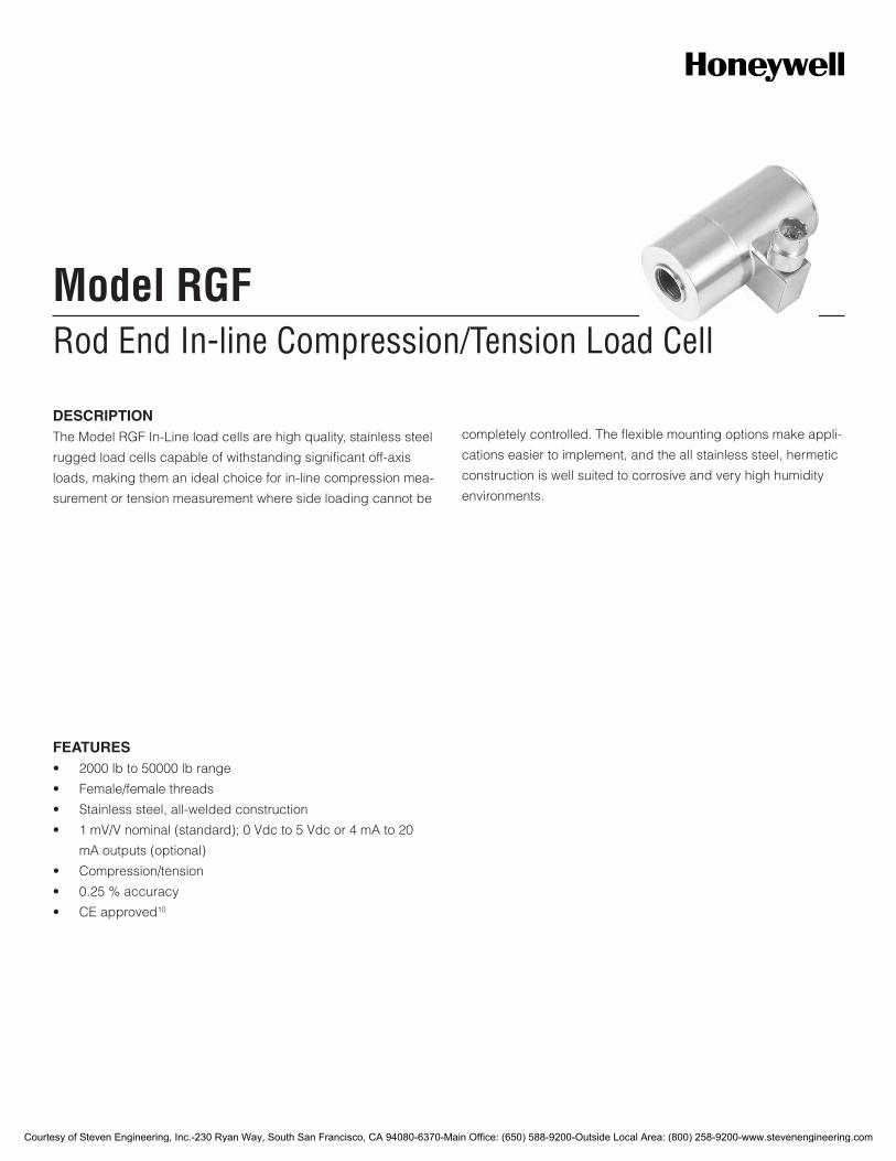
Rod End In-line Compression/Tension Load CellModel RGF
FEATURES• 2000lbto50000lbrange
• Female/femalethreads
• Stainlesssteel,all-weldedconstruction
• 1mV/Vnominal(standard);0Vdcto5Vdcor4mAto20
mAoutputs(optional)
• Compression/tension
• 0.25%accuracy
• CEapproved10
DESCRIPTIONTheModelRGFIn-Lineloadcellsarehighquality,stainlesssteel
ruggedloadcellscapableofwithstandingsignificantoff-axis
loads,makingthemanidealchoiceforin-linecompressionmea-
surementortensionmeasurementwheresideloadingcannotbe
completelycontrolled.Theflexiblemountingoptionsmakeappli-
cationseasiertoimplement,andtheallstainlesssteel,hermetic
constructioniswellsuitedtocorrosiveandveryhighhumidity
environments.
Courtesy of Steven Engineering, Inc.-230 Ryan Way, South San Francisco, CA 94080-6370-Main Office: (650) 588-9200-Outside Local Area: (800) 258-9200-www.stevenengineering.com

2Honeywell•SensingandControl
Model RGFPERFORMANCE SPECIFICATIONS
Characteristic Measure
Loadranges11 2000,3000,5000,10000,15000,25000,50000lb
Accuracy ±0.25%fullscale1
Linearity ±0.25%fullscale
Hysteresis ±0.25%fullscale
Non-repeatability ±0.05%fullscale
Output(tolerance) 1mV/V(nominal)
Operation Tension/compression
Resolution Infinite
ENVIRONMENTAL SPECIFICATIONS
Characteristic Measure
Temperature,operating -54°Cto121°C[-65°Fto250°F]
Temperature,compensated 15°Cto71°C[60°Fto160°F]
Temperatureeffect,zero 0.005%fullscale/°F
Temperatureeffect,span 0.005%fullscale/°F
ELECTRICAL SPECIFICATIONS
Characteristic Measure
Straingagetype Bondedfoil
Excitation(calibration) 10Vdc
Excitation(acceptable) Upto15VdcorVac
Insulationresistance 5000mOhm@50Vdc
Bridgeresistance(toler-ance)
700ohm
Shuntcalibrationdata Included
Electricaltermination(std) PTIH-10-6Porequivalent(hermeticstainless)
MECHANICAL SPECIFICATIONS
Characteristic Measure
Maximumallowableload 150%FS1
Casematerial Stainlesssteel
Lifecycles(approx) >10millioncycles
Deflectionfullscale 0,076mm[0.003in]
RANGE CODES
Range Code Available ranges
DL 2000lb
DN 3000lb
DR 5000lb
DV 10000lb
EJ 15000lb
EM 25000lb
EP 50000lb
WIRING CODES
Connector Unamplified (Std.)
A (+)excitation
B (+)excitation
C (-)excitation
D (-)excitation
E (-)output
F (+)output
DEFLECTIONS AND RINGING FREQUENCIES
Capacity (lb) Deflection at full scale mm [in]
Ringing fre-quency (Hz)
Weight kg [lb]
2000 0,025[0.001] 10000 0,55[1.2]
3000 0,025[0.001] 12000 0,55[1.2]
5000 0,050[0.002] 15000 0,63[1.4]
10000 0,050[0.002] 10000 1,3[2.9]
15000 0,050[0.002] 10000 1,3[2.9]
25000 0,050[0.002] 6500 4,3[9.5]
50000 0,076[0.003] 7000 4,49[9.9]
Courtesy of Steven Engineering, Inc.-230 Ryan Way, South San Francisco, CA 94080-6370-Main Office: (650) 588-9200-Outside Local Area: (800) 258-9200-www.stevenengineering.com
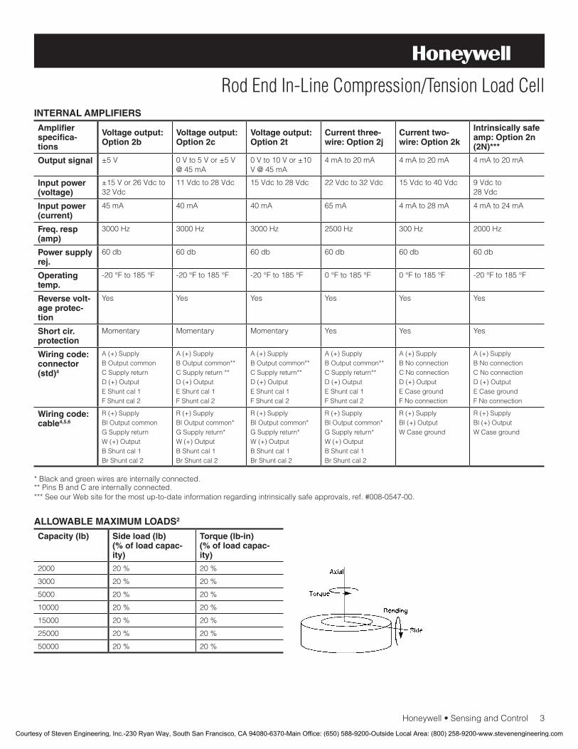
Honeywell•SensingandControl3
Rod End In-Line Compression/Tension Load CellINTERNAL AMPLIFIERS
Amplifier specifica-tions
Voltage output: Option 2b
Voltage output: Option 2c
Voltage output: Option 2t
Current three-wire: Option 2j
Current two-wire: Option 2k
Intrinsically safe amp: Option 2n (2N)***
Output signal ±5V 0Vto5Vor±5V@45mA
0Vto10Vor±10V@45mA
4mAto20mA 4mAto20mA 4mAto20mA
Input power (voltage)
±15Vor26Vdcto32Vdc
11Vdcto28Vdc 15Vdcto28Vdc 22Vdcto32Vdc 15Vdcto40Vdc 9Vdcto28Vdc
Input power (current)
45mA 40mA 40mA 65mA 4mAto28mA 4mAto24mA
Freq. resp (amp)
3000Hz 3000Hz 3000Hz 2500Hz 300Hz 2000Hz
Power supply rej.
60db 60db 60db 60db 60db 60db
Operating temp.
-20°Fto185°F -20°Fto185°F -20°Fto185°F 0°Fto185°F 0°Fto185°F -20°Fto185°F
Reverse volt-age protec-tion
Yes Yes Yes Yes Yes Yes
Short cir. protection
Momentary Momentary Momentary Yes Yes Yes
Wiring code: connector (std)4
A(+)SupplyBOutputcommonCSupplyreturnD(+)OutputEShuntcal1FShuntcal2
A(+)SupplyBOutputcommon**CSupplyreturn**D(+)OutputEShuntcal1FShuntcal2
A(+)SupplyBOutputcommon**CSupplyreturn**D(+)OutputEShuntcal1FShuntcal2
A(+)SupplyBOutputcommon**CSupplyreturn**D(+)OutputEShuntcal1FShuntcal2
A(+)SupplyBNoconnectionCNoconnectionD(+)OutputECasegroundFNoconnection
A(+)SupplyBNoconnectionCNoconnectionD(+)OutputECasegroundFNoconnection
Wiring code: cable4,5,6
R(+)SupplyBlOutputcommonGSupplyreturnW(+)OutputBShuntcal1BrShuntcal2
R(+)SupplyBlOutputcommon*GSupplyreturn*W(+)OutputBShuntcal1BrShuntcal2
R(+)SupplyBlOutputcommon*GSupplyreturn*W(+)OutputBShuntcal1BrShuntcal2
R(+)SupplyBlOutputcommon*GSupplyreturn*W(+)OutputBShuntcal1BrShuntcal2
R(+)SupplyBl(+)OutputWCaseground
R(+)SupplyBl(+)OutputWCaseground
*Blackandgreenwiresareinternallyconnected.**PinsBandCareinternallyconnected.***SeeourWebsiteforthemostup-to-dateinformationregardingintrinsicallysafeapprovals,ref.#008-0547-00.
ALLOWABLE MAXIMUM LOADS2
Capacity (lb) Side load (lb) (% of load capac-ity)
Torque (lb-in)(% of load capac-ity)
2000 20% 20%
3000 20% 20%
5000 20% 20%
10000 20% 20%
15000 20% 20%
25000 20% 20%
50000 20% 20%
Courtesy of Steven Engineering, Inc.-230 Ryan Way, South San Francisco, CA 94080-6370-Main Office: (650) 588-9200-Outside Local Area: (800) 258-9200-www.stevenengineering.com

4Honeywell•SensingandControl
Model RGFOPTION CODES
Many range/option combinations are available in our quick-ship and fast-track manufacture programs. Please see http://sensing.honeywell.com/TMsensor-ship for updated listings.
Load ranges 2K,3K,5K,10K,15K,25K,50Klb
Temperature compensa-tion
1a.60°Fto160°F1b.30°Fto130°F1c.0°Fto185°F1d.-20°Fto130°F1e.-20°Fto200°F1f.70°Fto250°F
1g.70°Fto325°F8
1h.70°Fto400°F8
1i.-65°Fto250°F8
1j.0°Cto50°C1k.-20°Cto85°C1m.-25°Cto110°C
Internal amplifiers
2u.Unamplified,mV/Voutput2b.4wire,±5Vdcoutput2c.0Vdcto5Vdc
2j.4mAto20mA(three-wire)output2k.4mAto20mA(two-wire)13
2t.0Vdcto10Vdcoutput
Internal amp enhance-ments
3a.Input/outputisolation7
3d.Remotebufferedshuntcalibration
Electrical termination
6a.BendixPTIH-10-6P(orequivalent)6-pin,(max.250°F)(ranges50000lbandbelow)
6b.MSconnectorMS3102E-14S-6P(mateswithMS3106E-14S-6),(max.160°F)(rangesabove50000lb)6
6e.Integralcable:Teflon6f.Integralcable:PVC
6g.Integralcable:Neoprene6h.Integralcable:Silicone6i.Integralunderwatercable6j.1/2-14conduitfittingwith5ftof4conductorPVCcable6q.Integralcable:Polyurethane6v.Phoenixconnectoronendofcable
Shunt calibration
8a.Precisioninternalresistor8
Bridge type 11a.Squarebridge8
11b.Symmetricalbridge811c.Squareandsymmetricalbridge831a.Dualbridge
Bridge resistance
12b.5000ohm(foil)(max.250°F)
Zero and span adjustment
14a.Noaccesstozeroandspanadjustment
Electrical connector orientation
15a.Horizontalelectricalexitportorientation15b.Verticalelectricalexitportorientation15c.Radialelectricalexitportorientation15d.Connectoronendofcable
Shock and vibration
44a.Shockandvibrationresistance
Interfaces 53e.Signaturecalibration8
53t.TEDSIEEE1451.4module9
Courtesy of Steven Engineering, Inc.-230 Ryan Way, South San Francisco, CA 94080-6370-Main Office: (650) 588-9200-Outside Local Area: (800) 258-9200-www.stevenengineering.com
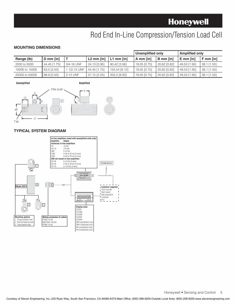
Honeywell•SensingandControl5
Rod End In-Line Compression/Tension Load CellMOUNTING DIMENSIONS
TYPICAL SYSTEM DIAGRAM
Unamplified only Amplified only
Range (lb) D mm [in] T L2 mm [in] L1 mm [in] A mm [in] B mm [in] E mm [in] F mm [in]
2000to5000 44,45[1.75] 3/4-16UNF 24,13[0.95] 90,42[3.56] 19,05[0.75] 20,82[0.82] 49,53[1.95] 38,1[1.50]
10000to15000 63,5[2.50] 11/2-12UNF 44,45[1.75] 155,54[6.12] 19,05[0.75] 20,82[0.82] 49,53[1.95] 38,1[1.50]
25000to50000 88,9[3.50] 2-12UNF 57,15[2.25] 203,2[8.00] 19,05[0.75] 20,82[0.82] 49,53[1.95] 38,1[1.50]
Courtesy of Steven Engineering, Inc.-230 Ryan Way, South San Francisco, CA 94080-6370-Main Office: (650) 588-9200-Outside Local Area: (800) 258-9200-www.stevenengineering.com
008659-2-EN IL50 GLO January 2010Copyright © 2010 Honeywell International Inc. All rights reserved.
Model RGF Rod End In-Line Compression/Tension Load Cell
Sensing and Control
Honeywell
1985 Douglas Drive North
Golden Valley, MN 55422
www.honeywell.com
NOTES
1. Allowablemaximumloads–maximumloadtobeappliedwithoutdamage.2
2. Withoutdamage-loadingtothislevelwillnotcauseexcessivezeroshiftorperformancedegradation.Theusermustconsiderfatiguelifeforlongtermuseandstructuralintegrity.Allstructurallycriticalapplications(overheadloading,etc.)shouldalwaysbedesignedwithsafetyredundantloadpaths.
3. Interconnectingshuntcal.1terminalwithshuntcal.2terminalprovides50%(unamplifiedunits),75%(4mAto20mAthree-wireunits)or80%(voltageamplifiedunits)offullscaleoutputforquickcalibration.Shuntcalibrationcomesstandardwithinternalampli-fieroption2a,2b,2c,2tand2j.
4. O=Orange;Y=Yellow;B=Blue;Bl=Black;R=Red;Br=Brown;W=White;G=Green.Colorspecifyingcableandnumberorletterspecifyingconnector.
5. Nomatingconnectornecessaryforcableoption.6. Cannotbeusedwithoptions1c,1e,1f,1g,1h,or1i.7. Onlyavailablewithoption2bor2c.8. Notavailablewithamplifiedoption.9. ConsultfactoryforTEDSavailabilitywithamplifiedmodels.10. Terminationdependent;consultfactory.11. ThisunitcalibratedtoImperial(non-Metric)units.12. 5000ohmbridgerequired.
Find out more
Honeywellservesitscustomers
throughaworldwidenetworkof
salesoffices,representatives
anddistributors.Forapplication
assistance,currentspecifica-
tions,pricingornameofthe
nearestAuthorizedDistributor,
contactyourlocalsalesoffice.
TolearnmoreaboutHoneywell’s
testandmeasurementproducts,
call+1-614-850-5000,visit
www.honeywell.com/sensotec,
ore-mailinquiriesto
Warranty. Honeywellwarrantsgoodsofitsmanufactureasbeingfreeofdefectivematerialsandfaultyworkmanship.Honeywell’sstandardproductwarrantyappliesunlessagreedtootherwisebyHoneywellinwriting;pleaserefertoyourorderacknowledgementorconsultyourlocalsalesofficeforspecificwarrantydetails.IfwarrantedgoodsarereturnedtoHoneywellduringtheperiodofcoverage,Honeywellwillrepairorreplace,atitsoption,withoutchargethoseitemsitfindsdefective.The foregoing is buyer’s sole remedy and is in lieu of all warranties, expressed or implied, including those of merchantability and fitness for a particular purpose. In no event shall Honeywell be liable for consequential, special, or indirect damages.
Whileweprovideapplicationassistancepersonally,throughourliteratureandtheHoneywellwebsite,itisuptothecustomertodeterminethesuitabilityoftheproductintheapplication.
Specificationsmaychangewithoutnotice.Theinformationwesupplyisbelievedtobeaccurateandreliableasofthisprinting.However,weassumenoresponsibilityforitsuse.
WARNINGPERSONAL INJURY
•DONOTUSEtheseproductsassafetyoremergencystopdevicesorinanyotherapplicationwherefailureoftheproductcouldresultinpersonalinjury.
Failure to comply with these instructions could result in death or serious injury.
WARNINGMISUSE OF DOCUMENTATION
•Theinformationpresentedinthisdatasheetisforreferenceonly.DONOTUSEthisdocumentasproductinstallationinformation.
•Completeinstallation,operationandmaintenanceinformationisprovidedintheinstructionssuppliedwitheachproduct.
Failure to comply with these instructions could result in death or serious injury.
Courtesy of Steven Engineering, Inc.-230 Ryan Way, South San Francisco, CA 94080-6370-Main Office: (650) 588-9200-Outside Local Area: (800) 258-9200-www.stevenengineering.com
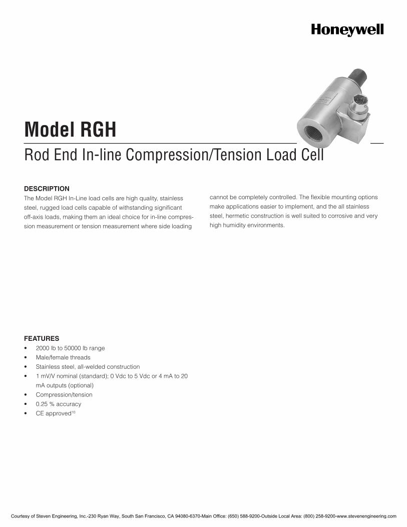
Rod End In-line Compression/Tension Load CellModel RGH
DESCRIPTIONThe Model RGH In-Line load cells are high quality, stainless
steel, rugged load cells capable of withstanding significant
off-axis loads, making them an ideal choice for in-line compres-
sion measurement or tension measurement where side loading
cannot be completely controlled. The flexible mounting options
make applications easier to implement, and the all stainless
steel, hermetic construction is well suited to corrosive and very
high humidity environments.
FEATURES• 2000lbto50000lbrange
• Male/femalethreads
• Stainlesssteel,all-weldedconstruction
• 1mV/Vnominal(standard);0Vdcto5Vdcor4mAto20
mAoutputs(optional)
• Compression/tension
• 0.25%accuracy
• CEapproved10
Courtesy of Steven Engineering, Inc.-230 Ryan Way, South San Francisco, CA 94080-6370-Main Office: (650) 588-9200-Outside Local Area: (800) 258-9200-www.stevenengineering.com
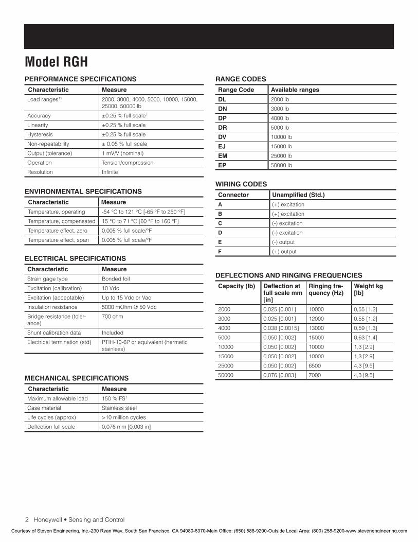
2Honeywell•SensingandControl
Model RGHPERFORMANCE SPECIFICATIONS
Characteristic Measure
Load ranges11 2000,3000,4000,5000,10000,15000,25000,50000lb
Accuracy ±0.25%fullscale1
Linearity ±0.25%fullscale
Hysteresis ±0.25%fullscale
Non-repeatability ±0.05%fullscale
Output(tolerance) 1mV/V(nominal)
Operation Tension/compression
Resolution Infinite
ENVIRONMENTAL SPECIFICATIONS
Characteristic Measure
Temperature, operating -54°Cto121°C[-65°Fto250°F]
Temperature, compensated 15°Cto71°C[60°Fto160°F]
Temperature effect, zero 0.005%fullscale/°F
Temperature effect, span 0.005%fullscale/°F
ELECTRICAL SPECIFICATIONS
Characteristic Measure
Straingagetype Bonded foil
Excitation(calibration) 10Vdc
Excitation(acceptable) Upto15VdcorVac
Insulation resistance 5000mOhm@50Vdc
Bridgeresistance(toler-ance)
700ohm
Shuntcalibrationdata Included
Electricaltermination(std) PTIH-10-6Porequivalent(hermeticstainless)
MECHANICAL SPECIFICATIONS
Characteristic Measure
Maximum allowable load 150%FS1
Casematerial Stainlesssteel
Lifecycles(approx) >10millioncycles
Deflection full scale 0,076mm[0.003in]
RANGE CODES
Range Code Available ranges
DL 2000lb
DN 3000lb
DP 4000lb
DR 5000lb
DV 10000lb
EJ 15000lb
EM 25000lb
EP 50000lb
WIRING CODES
Connector Unamplified (Std.)
A (+)excitation
B (+)excitation
C (-)excitation
D (-)excitation
E (-)output
F (+)output
DEFLECTIONS AND RINGING FREQUENCIES
Capacity (lb) Deflection at full scale mm [in]
Ringing fre-quency (Hz)
Weight kg [lb]
2000 0,025[0.001] 10000 0,55[1.2]
3000 0,025[0.001] 12000 0,55[1.2]
4000 0.038[0.0015] 13000 0,59[1.3]
5000 0,050[0.002] 15000 0,63[1.4]
10000 0,050[0.002] 10000 1,3[2.9]
15000 0,050[0.002] 10000 1,3[2.9]
25000 0,050[0.002] 6500 4,3[9.5]
50000 0,076[0.003] 7000 4,3[9.5]
Courtesy of Steven Engineering, Inc.-230 Ryan Way, South San Francisco, CA 94080-6370-Main Office: (650) 588-9200-Outside Local Area: (800) 258-9200-www.stevenengineering.com
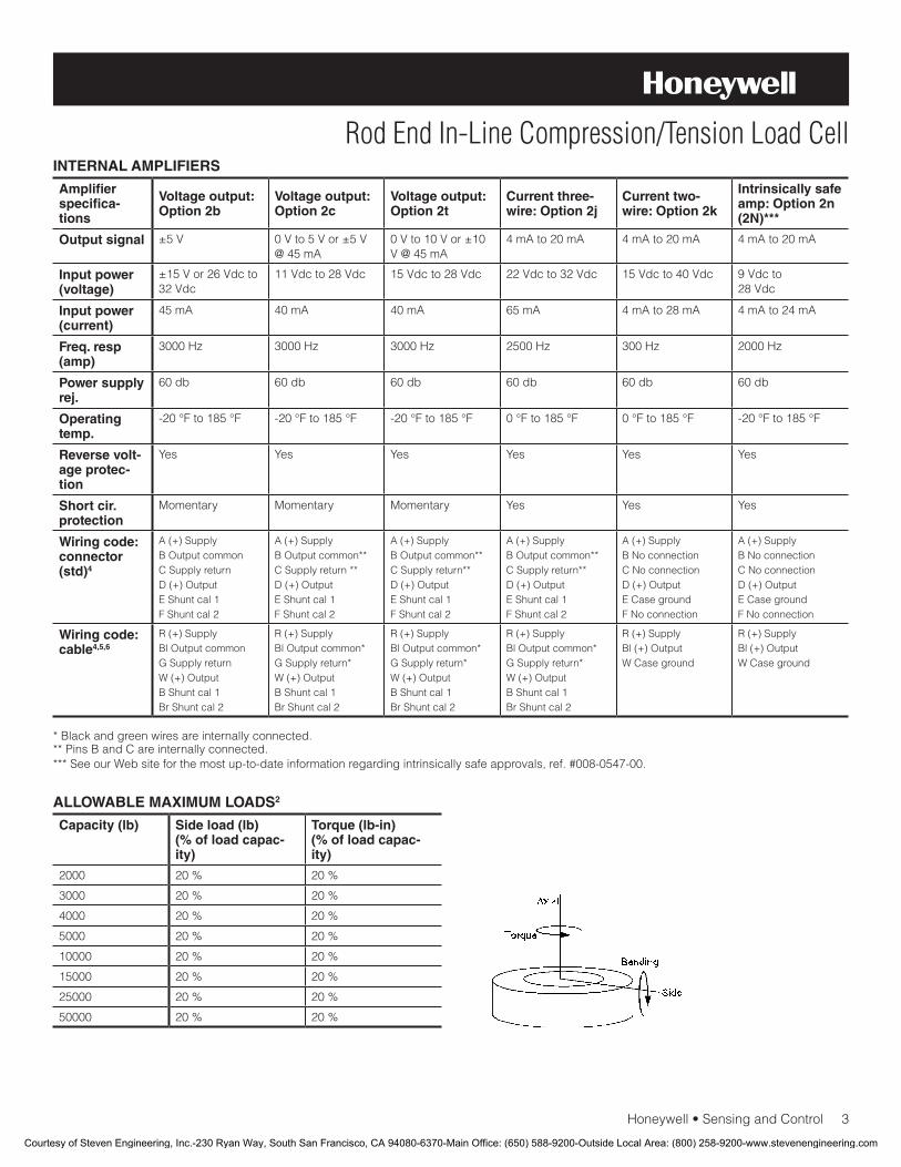
Honeywell•SensingandControl3
Rod End In-Line Compression/Tension Load CellINTERNAL AMPLIFIERS
Amplifier specifica-tions
Voltage output: Option 2b
Voltage output: Option 2c
Voltage output: Option 2t
Current three-wire: Option 2j
Current two-wire: Option 2k
Intrinsically safe amp: Option 2n (2N)***
Output signal ±5V 0Vto5Vor±5V@45mA
0Vto10Vor±10V@45mA
4mAto20mA 4mAto20mA 4mAto20mA
Input power (voltage)
±15Vor26Vdcto32Vdc
11Vdcto28Vdc 15Vdcto28Vdc 22Vdcto32Vdc 15Vdcto40Vdc 9Vdcto 28Vdc
Input power (current)
45mA 40mA 40mA 65mA 4mAto28mA 4mAto24mA
Freq. resp (amp)
3000Hz 3000Hz 3000Hz 2500Hz 300Hz 2000Hz
Power supply rej.
60db 60db 60db 60db 60db 60db
Operating temp.
-20°Fto185°F -20°Fto185°F -20°Fto185°F 0°Fto185°F 0°Fto185°F -20°Fto185°F
Reverse volt-age protec-tion
Yes Yes Yes Yes Yes Yes
Short cir. protection
Momentary Momentary Momentary Yes Yes Yes
Wiring code: connector (std)4
A(+)SupplyB Output commonCSupplyreturnD(+)OutputEShuntcal1FShuntcal2
A(+)SupplyB Output common**CSupplyreturn**D(+)OutputEShuntcal1FShuntcal2
A(+)SupplyB Output common**CSupplyreturn**D(+)OutputEShuntcal1FShuntcal2
A(+)SupplyB Output common**CSupplyreturn**D(+)OutputEShuntcal1FShuntcal2
A(+)SupplyB No connectionCNoconnectionD(+)OutputECasegroundFNoconnection
A(+)SupplyB No connectionCNoconnectionD(+)OutputECasegroundFNoconnection
Wiring code: cable4,5,6
R(+)SupplyBl Output commonGSupplyreturnW(+)OutputBShuntcal1BrShuntcal2
R(+)SupplyBl Output common*GSupplyreturn*W(+)OutputBShuntcal1BrShuntcal2
R(+)SupplyBl Output common*GSupplyreturn*W(+)OutputBShuntcal1BrShuntcal2
R(+)SupplyBl Output common*GSupplyreturn*W(+)OutputBShuntcal1BrShuntcal2
R(+)SupplyBl(+)OutputWCaseground
R(+)SupplyBl(+)OutputWCaseground
* Black and green wires are internally connected.**PinsBandCareinternallyconnected.***SeeourWebsiteforthemostup-to-dateinformationregardingintrinsicallysafeapprovals,ref.#008-0547-00.
ALLOWABLE MAXIMUM LOADS2
Capacity (lb) Side load (lb) (% of load capac-ity)
Torque (lb-in)(% of load capac-ity)
2000 20% 20%
3000 20% 20%
4000 20% 20%
5000 20% 20%
10000 20% 20%
15000 20% 20%
25000 20% 20%
50000 20% 20%
Courtesy of Steven Engineering, Inc.-230 Ryan Way, South San Francisco, CA 94080-6370-Main Office: (650) 588-9200-Outside Local Area: (800) 258-9200-www.stevenengineering.com
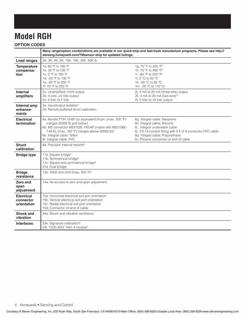
4Honeywell•SensingandControl
Model RGHOPTION CODES
Many range/option combinations are available in our quick-ship and fast-track manufacture programs. Please see http://sensing.honeywell.com/TMsensor-ship for updated listings.
Load ranges 2K,3K,4K,5K,10K,15K,25K,50Klb
Temperature compensa-tion
1a.60°Fto160°F1b.30°Fto130°F1c.0°Fto185°F1d.-20°Fto130°F1e.-20°Fto200°F1f.70°Fto250°F
1g.70°Fto325°F8
1h.70°Fto400°F8
1i.-65°Fto250°F8
1j.0°Cto50°C1k.-20°Cto85°C1m.-25°Cto110°C
Internal amplifiers
2u.Unamplified,mV/Voutput2b.4wire,±5Vdcoutput2c.0Vdcto5Vdc
2j.4mAto20mA(three-wire)output2k.4mAto20mA(two-wire)13
2t.0Vdcto10Vdcoutput
Internal amp enhance-ments
3a.Input/outputisolation7
3d.Remotebufferedshuntcalibration
Electrical termination
6a.BendixPTIH-10-6P(orequivalent)6-pin,(max.250°F)(ranges50000lbandbelow)
6b.MSconnectorMS3102E-14S-6P(mateswithMS3106E-14S-6),(max.160°F)(rangesabove50000lb)6
6e.Integralcable:Teflon6f.Integralcable:PVC
6g.Integralcable:Neoprene6h.Integralcable:Silicone6i.Integralunderwatercable6j.1/2-14conduitfittingwith5ftof4conductorPVCcable6q.Integralcable:Polyurethane6v.Phoenixconnectoronendofcable
Shunt calibration
8a.Precisioninternalresistor8
Bridge type 11a.Squarebridge8
11b.Symmetricalbridge8 11c.Squareandsymmetricalbridge8 31a.Dualbridge
Bridge resistance
12b.5000ohm(foil)(max.250°F)
Zero and span adjustment
14a.Noaccesstozeroandspanadjustment
Electrical connector orientation
15a.Horizontalelectricalexitportorientation15b.Verticalelectricalexitportorientation15c.Radialelectricalexitportorientation15d.Connectoronendofcable
Shock and vibration
44a.Shockandvibrationresistance
Interfaces 53e.Signaturecalibration8
53t.TEDSIEEE1451.4module9
Courtesy of Steven Engineering, Inc.-230 Ryan Way, South San Francisco, CA 94080-6370-Main Office: (650) 588-9200-Outside Local Area: (800) 258-9200-www.stevenengineering.com
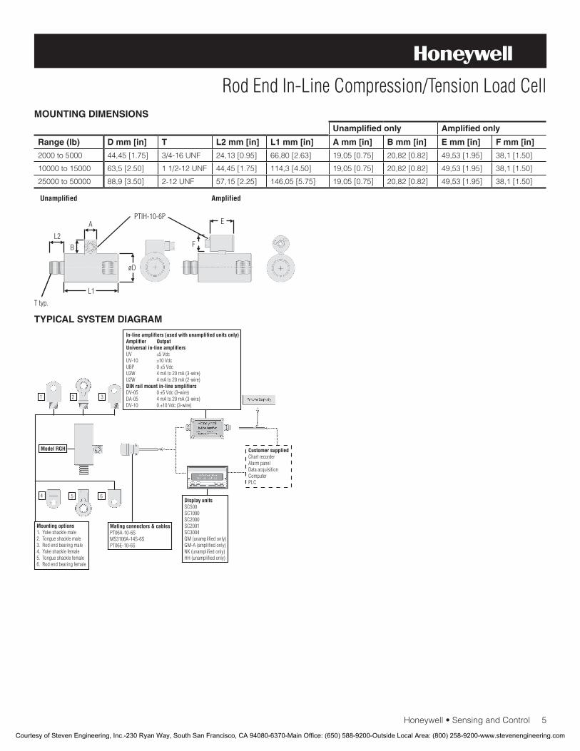
Honeywell•SensingandControl5
Rod End In-Line Compression/Tension Load CellMOUNTING DIMENSIONS
TYPICAL SYSTEM DIAGRAM
Unamplified only Amplified only
Range (lb) D mm [in] T L2 mm [in] L1 mm [in] A mm [in] B mm [in] E mm [in] F mm [in]
2000to5000 44,45[1.75] 3/4-16UNF 24,13[0.95] 66,80[2.63] 19,05[0.75] 20,82[0.82] 49,53[1.95] 38,1[1.50]
10000to15000 63,5[2.50] 11/2-12UNF 44,45[1.75] 114,3[4.50] 19,05[0.75] 20,82[0.82] 49,53[1.95] 38,1[1.50]
25000to50000 88,9[3.50] 2-12UNF 57,15[2.25] 146,05[5.75] 19,05[0.75] 20,82[0.82] 49,53[1.95] 38,1[1.50]
Courtesy of Steven Engineering, Inc.-230 Ryan Way, South San Francisco, CA 94080-6370-Main Office: (650) 588-9200-Outside Local Area: (800) 258-9200-www.stevenengineering.com
008658-2-EN IL50 GLO January 2010Copyright © 2010 Honeywell International Inc. All rights reserved.
Model RGH Rod End In-Line Compression/Tension Load Cell
Sensing and Control
Honeywell
1985 Douglas Drive North
Golden Valley, MN 55422
www.honeywell.com
NOTES
1. Allowablemaximumloads–maximumloadtobeappliedwithoutdamage.2
2. Withoutdamage-loadingtothislevelwillnotcauseexcessivezeroshift or performance degradation. The user must consider fatigue lifeforlongtermuseandstructuralintegrity.Allstructurallycriticalapplications(overheadloading,etc.)shouldalwaysbedesignedwith safety redundant load paths.
3. Interconnectingshuntcal.1terminalwithshuntcal.2terminalprovides50%(unamplifiedunits),75%(4mAto20mAthree-wireunits)or80%(voltageamplifiedunits)offullscaleoutputforquickcalibration.Shuntcalibrationcomesstandardwithinternalampli-fieroption2a,2b,2c,2tand2j.
4. O=Orange;Y=Yellow;B=Blue;Bl=Black;R=Red;Br=Brown;W=White;G=Green.Colorspecifyingcableandnumberorletterspecifying connector.
5. Nomatingconnectornecessaryforcableoption.6. Cannotusewithoptions1c,1e,1f,1g,1h,or1i.7. Onlyavailablewithoption2bor2c.8. Notavailablewithamplifiedoption.9. ConsultfactoryforTEDSavailabilitywithamplifiedmodels.10. Terminationdependent;consultfactory.11. ThisunitcalibratedtoImperial(non-Metric)units.12. 5000ohmbridgerequired.
Warranty. Honeywell warrants goods of its manufacture as being free of defective materials and faulty workmanship. Honeywell’s standard product warranty applies unless agreed tootherwisebyHoneywellinwriting;pleaserefertoyourorder acknowledgement or consult your local sales office for specific warranty details. If warranted goods are returned to Honeywell during the period of coverage, Honeywell will repair or replace, at its option, without charge those items it finds defective. The foregoing is buyer’s sole remedy and is in lieu of all warranties, expressed or implied, including those of merchantability and fitness for a particular purpose. In no event shall Honeywell be liable for consequential, special, or indirect damages.
While we provide application assistance personally, through our literature and the Honeywell web site, it is up to the customer to determine the suitability of the product in the application.
WARNINGPERSONAL INJURY
•DONOTUSEtheseproductsassafetyoremergencystop devices or in any other application where failure of theproductcouldresultinpersonalinjury.
Failure to comply with these instructions could result in death or serious injury.
WARNINGMISUSE OF DOCUMENTATION
•Theinformationpresentedinthisdatasheetisforreferenceonly.DONOTUSEthisdocumentasproductinstallation information.
•Completeinstallation,operationandmaintenanceinformation is provided in the instructions supplied with each product.
Failure to comply with these instructions could result in death or serious injury.
Find out more
Honeywell serves its customers
through a worldwide network of
sales offices, representatives
anddistributors.Forapplication
assistance, current specifica-
tions, pricing or name of the
nearestAuthorizedDistributor,
contact your local sales office.
To learn more about Honeywell’s
test and measurement products,
call +1-614-850-5000, visit
www.honeywell.com/sensotec,
or e-mail inquiries to
Courtesy of Steven Engineering, Inc.-230 Ryan Way, South San Francisco, CA 94080-6370-Main Office: (650) 588-9200-Outside Local Area: (800) 258-9200-www.stevenengineering.com
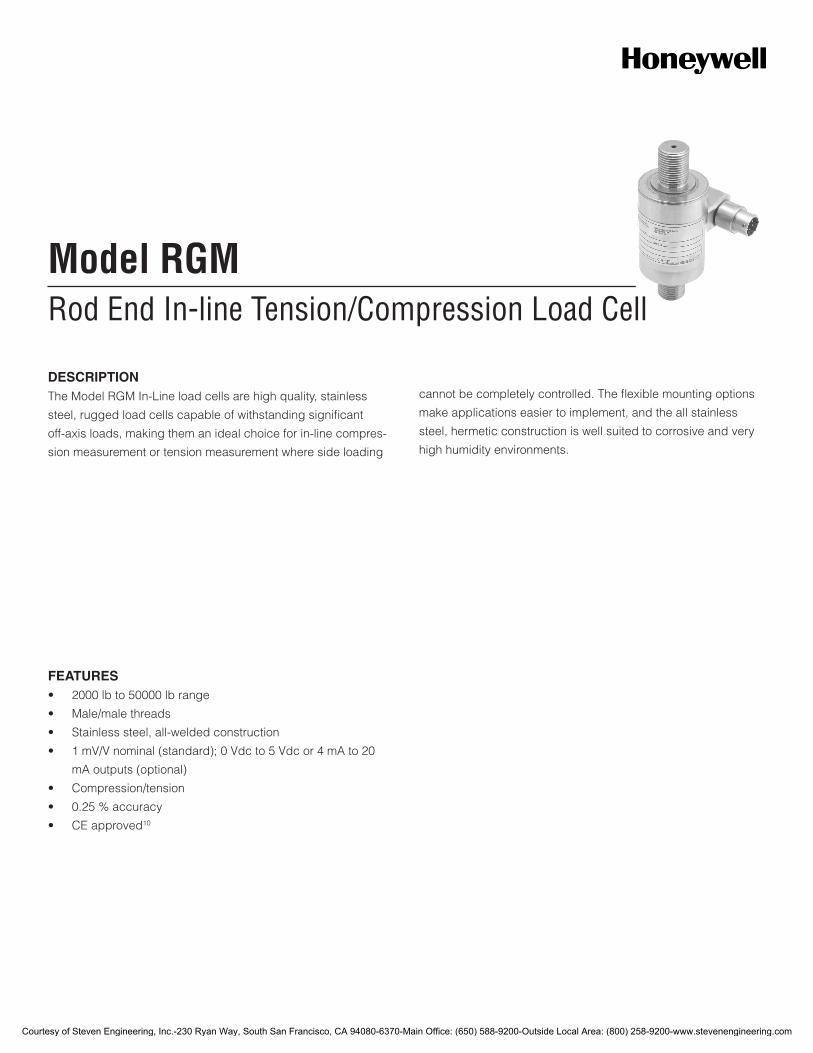
Rod End In-line Tension/Compression Load CellModel RGM
FEATURES• 2000lbto50000lbrange
• Male/malethreads
• Stainlesssteel,all-weldedconstruction
• 1mV/Vnominal(standard);0Vdcto5Vdcor4mAto20
mAoutputs(optional)
• Compression/tension
• 0.25%accuracy
• CEapproved10
DESCRIPTIONTheModelRGMIn-Lineloadcellsarehighquality,stainless
steel,ruggedloadcellscapableofwithstandingsignificant
off-axisloads,makingthemanidealchoiceforin-linecompres-
sionmeasurementortensionmeasurementwheresideloading
cannotbecompletelycontrolled.Theflexiblemountingoptions
makeapplicationseasiertoimplement,andtheallstainless
steel,hermeticconstructioniswellsuitedtocorrosiveandvery
highhumidityenvironments.
Courtesy of Steven Engineering, Inc.-230 Ryan Way, South San Francisco, CA 94080-6370-Main Office: (650) 588-9200-Outside Local Area: (800) 258-9200-www.stevenengineering.com
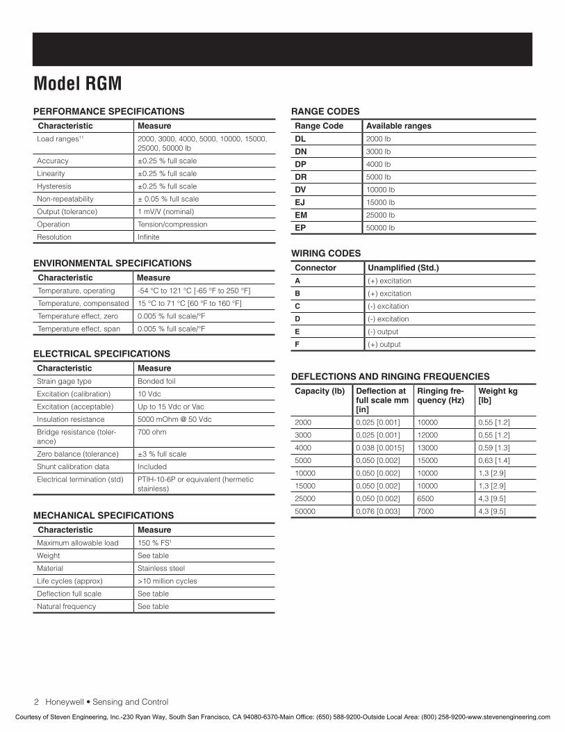
2Honeywell•SensingandControl
Model RGMPERFORMANCE SPECIFICATIONS
Characteristic Measure
Loadranges11 2000,3000,4000,5000,10000,15000,25000,50000lb
Accuracy ±0.25%fullscale
Linearity ±0.25%fullscale
Hysteresis ±0.25%fullscale
Non-repeatability ±0.05%fullscale
Output(tolerance) 1mV/V(nominal)
Operation Tension/compression
Resolution Infinite
ENVIRONMENTAL SPECIFICATIONS
Characteristic Measure
Temperature,operating -54°Cto121°C[-65°Fto250°F]
Temperature,compensated 15°Cto71°C[60°Fto160°F]
Temperatureeffect,zero 0.005%fullscale/°F
Temperatureeffect,span 0.005%fullscale/°F
ELECTRICAL SPECIFICATIONS
Characteristic Measure
Straingagetype Bondedfoil
Excitation(calibration) 10Vdc
Excitation(acceptable) Upto15VdcorVac
Insulationresistance 5000mOhm@50Vdc
Bridgeresistance(toler-ance)
700ohm
Zerobalance(tolerance) ±3%fullscale
Shuntcalibrationdata Included
Electricaltermination(std) PTIH-10-6Porequivalent(hermeticstainless)
MECHANICAL SPECIFICATIONS
Characteristic Measure
Maximumallowableload 150%FS1
Weight Seetable
Material Stainlesssteel
Lifecycles(approx) >10millioncycles
Deflectionfullscale Seetable
Naturalfrequency Seetable
RANGE CODES
Range Code Available ranges
DL 2000lb
DN 3000lb
DP 4000lb
DR 5000lb
DV 10000lb
EJ 15000lb
EM 25000lb
EP 50000lb
WIRING CODES
Connector Unamplified (Std.)
A (+)excitation
B (+)excitation
C (-)excitation
D (-)excitation
E (-)output
F (+)output
DEFLECTIONS AND RINGING FREQUENCIES
Capacity (lb) Deflection at full scale mm [in]
Ringing fre-quency (Hz)
Weight kg [lb]
2000 0,025[0.001] 10000 0,55[1.2]
3000 0,025[0.001] 12000 0,55[1.2]
4000 0.038[0.0015] 13000 0,59[1.3]
5000 0,050[0.002] 15000 0,63[1.4]
10000 0,050[0.002] 10000 1,3[2.9]
15000 0,050[0.002] 10000 1,3[2.9]
25000 0,050[0.002] 6500 4,3[9.5]
50000 0,076[0.003] 7000 4,3[9.5]
Courtesy of Steven Engineering, Inc.-230 Ryan Way, South San Francisco, CA 94080-6370-Main Office: (650) 588-9200-Outside Local Area: (800) 258-9200-www.stevenengineering.com
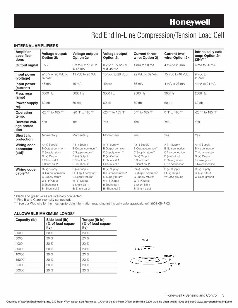
Honeywell•SensingandControl3
Rod End In-Line Compression/Tension Load CellINTERNAL AMPLIFIERS
Amplifier specifica-tions
Voltage output: Option 2b
Voltage output: Option 2c
Voltage output: Option 2t
Current three-wire: Option 2j
Current two-wire: Option 2k
Intrinsically safe amp: Option 2n (2N)***
Output signal ±5V 0Vto5Vor±5V@45mA
0Vto10Vor±10V@45mA
4mAto20mA 4mAto20mA 4mAto20mA
Input power (voltage)
±15Vor26Vdcto32Vdc
11Vdcto28Vdc 15Vdcto28Vdc 22Vdcto32Vdc 15Vdcto40Vdc 9Vdcto28Vdc
Input power (current)
45mA 40mA 40mA 65mA 4mAto28mA 4mAto24mA
Freq. resp (amp)
3000Hz 3000Hz 3000Hz 2500Hz 300Hz 2000Hz
Power supply rej.
60db 60db 60db 60db 60db 60db
Operating temp.
-20°Fto185°F -20°Fto185°F -20°Fto185°F 0°Fto185°F 0°Fto185°F -20°Fto185°F
Reverse volt-age protec-tion
Yes Yes Yes Yes Yes Yes
Short cir. protection
Momentary Momentary Momentary Yes Yes Yes
Wiring code: connector (std)4
A(+)SupplyBOutputcommonCSupplyreturnD(+)OutputEShuntcal1FShuntcal2
A(+)SupplyBOutputcommon**CSupplyreturn**D(+)OutputEShuntcal1FShuntcal2
A(+)SupplyBOutputcommon**CSupplyreturn**D(+)OutputEShuntcal1FShuntcal2
A(+)SupplyBOutputcommon**CSupplyreturn**D(+)OutputEShuntcal1FShuntcal2
A(+)SupplyBNoconnectionCNoconnectionD(+)OutputECasegroundFNoconnection
A(+)SupplyBNoconnectionCNoconnectionD(+)OutputECasegroundFNoconnection
Wiring code: cable4,5,6
R(+)SupplyBlOutputcommonGSupplyreturnW(+)OutputBShuntcal1BrShuntcal2
R(+)SupplyBlOutputcommon*GSupplyreturn*W(+)OutputBShuntcal1BrShuntcal2
R(+)SupplyBlOutputcommon*GSupplyreturn*W(+)OutputBShuntcal1BrShuntcal2
R(+)SupplyBlOutputcommon*GSupplyreturn*W(+)OutputBShuntcal1BrShuntcal2
R(+)SupplyBl(+)OutputWCaseground
R(+)SupplyBl(+)OutputWCaseground
*Blackandgreenwiresareinternallyconnected.**PinsBandCareinternallyconnected.***SeeourWebsiteforthemostup-to-dateinformationregardingintrinsicallysafeapprovals,ref.#008-0547-00.
ALLOWABLE MAXIMUM LOADS2
Capacity (lb) Side load (lb) (% of load capac-ity)
Torque (lb-in)(% of load capac-ity)
2000 20% 20%
3000 20% 20%
4000 20% 20%
5000 20% 20%
10000 20% 20%
15000 20% 20%
25000 20% 20%
50000 20% 20%
Courtesy of Steven Engineering, Inc.-230 Ryan Way, South San Francisco, CA 94080-6370-Main Office: (650) 588-9200-Outside Local Area: (800) 258-9200-www.stevenengineering.com
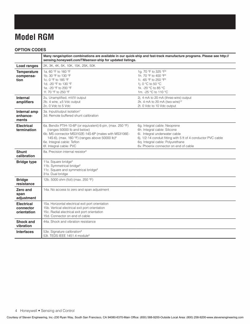
4Honeywell•SensingandControl
Model RGMOPTION CODES
Many range/option combinations are available in our quick-ship and fast-track manufacture programs. Please see http://sensing.honeywell.com/TMsensor-ship for updated listings.
Load ranges 2K,3K,4K,5K,10K,15K,25K,50K
Temperature compensa-tion
1a.60°Fto160°F1b.30°Fto130°F1c.0°Fto185°F1d.-20°Fto130°F1e.-20°Fto200°F1f.70°Fto250°F
1g.70°Fto325°F8
1h.70°Fto400°F8
1i.-65°Fto250°F8
1j.0°Cto50°C1k.-20°Cto85°C1m.-25°Cto110°C
Internal amplifiers
2u.Unamplified,mV/Voutput2b.4wire,±5Vdcoutput2c.0Vdcto5Vdc
2j.4mAto20mA(three-wire)output2k.4mAto20mA(two-wire)12
2t.0Vdcto10Vdcoutput
Internal amp enhance-ments
3a.Input/outputisolation7
3d.Remotebufferedshuntcalibration
Electrical termination
6a.BendixPTIH-10-6P(orequivalent)6-pin,(max.250°F)(ranges50000lbandbelow)
6b.MSconnectorMS3102E-14S-6P(mateswithMS3106E-14S-6),(max.160°F)(rangesabove50000lb)6
6e.Integralcable:Teflon6f.Integralcable:PVC
6g.Integralcable:Neoprene6h.Integralcable:Silicone6i.Integralunderwatercable6j.1/2-14conduitfittingwith5ftof4conductorPVCcable6q.Integralcable:Polyurethane6v.Phoenixconnectoronendofcable
Shunt calibration
8a.Precisioninternalresistor8
Bridge type 11a.Squarebridge8
11b.Symmetricalbridge811c.Squareandsymmetricalbridge831a.Dualbridge
Bridge resistance
12b.5000ohm(foil)(max.250°F)
Zero and span adjustment
14a.Noaccesstozeroandspanadjustment
Electrical connector orientation
15a.Horizontalelectricalexitportorientation15b.Verticalelectricalexitportorientation15c.Radialelectricalexitportorientation15d.Connectoronendofcable
Shock and vibration
44a.Shockandvibrationresistance
Interfaces 53e.Signaturecalibration8
53t.TEDSIEEE1451.4module9
Courtesy of Steven Engineering, Inc.-230 Ryan Way, South San Francisco, CA 94080-6370-Main Office: (650) 588-9200-Outside Local Area: (800) 258-9200-www.stevenengineering.com

Honeywell•SensingandControl5
Rod End In-Line Compression/Tension Load CellMOUNTING DIMENSIONS
TYPICAL SYSTEM DIAGRAM
Unamplified only Amplified only
Range (lb) D mm [in] T L2 mm [in] L1 mm [in] A mm [in] B mm [in] E mm [in] F mm [in]
2000to5000 44,45[1.75] 3/4-16UNF 24,13[0.95] 66,80[2.63] 19,05[0.75] 20,82[0.82] 49,53[1.95] 38,1[1.50]
10000to15000 63,5[2.50] 11/2-12UNF 44,45[1.75] 88,9[3.50] 19,05[0.75] 20,82[0.82] 49,53[1.95] 38,1[1.50]
25000to50000 88,9[3.50] 2-12UNF 57,15[2.25] 88,9[3.50] 19,05[0.75] 20,82[0.82] 49,53[1.95] 38,1[1.50]
Courtesy of Steven Engineering, Inc.-230 Ryan Way, South San Francisco, CA 94080-6370-Main Office: (650) 588-9200-Outside Local Area: (800) 258-9200-www.stevenengineering.com

008657-3-EN IL50 GLO January 2010Copyright © 2010 Honeywell International Inc. All rights reserved.
Model RGM Rod End In-Line Compression/Tension Load Cell
Sensing and Control
Honeywell
1985 Douglas Drive North
Golden Valley, MN 55422
www.honeywell.com
NOTES
1. Allowablemaximumloads–maximumloadtobeappliedwithoutdamage.2
2. Withoutdamage-loadingtothislevelwillnotcauseexcessivezeroshiftorperformancedegradation.Theusermustconsiderfatiguelifeforlongtermuseandstructuralintegrity.Allstructurallycriticalapplications(overheadloading,etc.)shouldalwaysbedesignedwithsafetyredundantloadpaths.
3. Interconnectingshuntcal.1terminalwithshuntcal.2terminalprovides50%(unamplifiedunits),75%(4mAto20mAthree-wireunits)or80%(voltageamplifiedunits)offullscaleoutputforquickcalibration.Shuntcalibrationcomesstandardwithinternalampli-fieroption2a,2b,2c,2tand2j.
4. O=Orange;Y=Yellow;B=Blue;Bl=Black;R=Red;Br=Brown;W=White;G=Green.Colorspecifyingcableandnumberorletterspecifyingconnector.
5. Nomatingconnectornecessaryforcableoption.6. Cannotbeusedwithoptions1c,1e,1f,1g,1h,or1i.7. Onlyavailablewithoption2bor2c.8. Notavailablewithamplifiedoption.9. ConsultfactoryforTEDSavailabilitywithamplifiedmodels.10. Terminationdependent;consultfactory.11. ThisunitcalibratedtoImperial(non-Metric)units.12. 5000ohmbridgerequired.
Find out more
Honeywellservesitscustomers
throughaworldwidenetworkof
salesoffices,representatives
anddistributors.Forapplication
assistance,currentspecifica-
tions,pricingornameofthe
nearestAuthorizedDistributor,
contactyourlocalsalesoffice.
TolearnmoreaboutHoneywell’s
testandmeasurementproducts,
call+1-614-850-5000,visit
www.honeywell.com/sensotec,
ore-mailinquiriesto
Warranty. Honeywellwarrantsgoodsofitsmanufactureasbeingfreeofdefectivematerialsandfaultyworkmanship.Honeywell’sstandardproductwarrantyappliesunlessagreedtootherwisebyHoneywellinwriting;pleaserefertoyourorderacknowledgementorconsultyourlocalsalesofficeforspecificwarrantydetails.IfwarrantedgoodsarereturnedtoHoneywellduringtheperiodofcoverage,Honeywellwillrepairorreplace,atitsoption,withoutchargethoseitemsitfindsdefective.The foregoing is buyer’s sole remedy and is in lieu of all warranties, expressed or implied, including those of merchantability and fitness for a particular purpose. In no event shall Honeywell be liable for consequential, special, or indirect damages.
Whileweprovideapplicationassistancepersonally,throughourliteratureandtheHoneywellwebsite,itisuptothecustomertodeterminethesuitabilityoftheproductintheapplication.
Specificationsmaychangewithoutnotice.Theinformationwesupplyisbelievedtobeaccurateandreliableasofthisprinting.However,weassumenoresponsibilityforitsuse.
WARNINGPERSONAL INJURY
•DONOTUSEtheseproductsassafetyoremergencystopdevicesorinanyotherapplicationwherefailureoftheproductcouldresultinpersonalinjury.
Failure to comply with these instructions could result in death or serious injury.
WARNINGMISUSE OF DOCUMENTATION
•Theinformationpresentedinthisdatasheetisforreferenceonly.DONOTUSEthisdocumentasproductinstallationinformation.
•Completeinstallation,operationandmaintenanceinformationisprovidedintheinstructionssuppliedwitheachproduct.
Failure to comply with these instructions could result in death or serious injury.
Courtesy of Steven Engineering, Inc.-230 Ryan Way, South San Francisco, CA 94080-6370-Main Office: (650) 588-9200-Outside Local Area: (800) 258-9200-www.stevenengineering.com

Tension/Compression In-Line Load CellModel 3124
DESCRIPTIONThe small-diameter, cost-efficient load cells are designed to
be used in applications that require an ability to mount in an
existing system with restricted working area. They are commonly
used in fluid power transfer systems. Their low cost and ease of
mounting allow simultaneous testing of multi-element systems.
They may be directly attached to the piston rod of a hydraulic
cylinder. Side-mounted cable connectors allow cable assemblies
to be supported without affecting movement of the cell during
tension or compression loading.
FEATURES• 5000lbto25000lbrange
• 0.25%non-linearity
• 0.15%hysteresis
• Adaptsdirectlytohydrauliccylinder
• Smalldiameterallowsmountinginrestrictedareas
• Lowdeflection
Courtesy of Steven Engineering, Inc.-230 Ryan Way, South San Francisco, CA 94080-6370-Main Office: (650) 588-9200-Outside Local Area: (800) 258-9200-www.stevenengineering.com
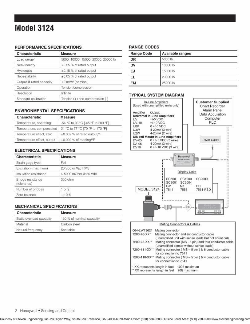
2Honeywell•SensingandControl
Model 3124
RANGE CODES
Range Code Available ranges
DR 5000lb
DV 10000lb
EJ 15000lb
EL 20000lb
EM 25000lb
PERFORMANCE SPECIFICATIONS
Characteristic Measure
Loadrange1 5000,10000,15000,20000,25000lb
Non-linearity ±0.25%ofratedoutput
Hysteresis ±0.15%ofratedoutput
Repeatability ±0.05%ofratedoutput
Output @ rated capacity ±2mV/V(nominal)
Operation Tension/compression
Resolution Infinite
Standard calibration Tension(+)andcompression(-)
ENVIRONMENTAL SPECIFICATIONS
Characteristic Measure
Temperature, operating -54°Cto93°C[-65°Fto200°F]
Temperature, compensated 21°Cto77°C[70°Fto170°F]
Temperature effect, zero ±0.002%ofratedoutput/°F
Temperature effect, output ±0.002%ofreading/°F
ELECTRICAL SPECIFICATIONS
Characteristic Measure
Strain gage type Foil
Excitation(maximum) 20VdcorVacRMS
Insulation resistance >5000mOhm@50Vdc
Bridge resistance (tolerance)
350ohm
Number of bridges 1or2
Zero balance ±1.0%
MECHANICAL SPECIFICATIONS
Characteristic Measure
Static overload capacity 150%ofnominalcapacity
Material Carbonsteel
Natural frequency See table
TYPICAL SYSTEM DIAGRAM
HoneywellIn-Line Amplifier
Output Input
Serial Number
Power Supply
Customer SuppliedChart Recorder
Alarm PanelData Acquisition
ComputerPLC
MODEL 3124
(Used with unamplified units only)
UVUV-10UBPU3WU2W
DV-05DA-05DV10
In-Line Amplifiers
AmplifierUniversal In-Line Amplifiers
DIN rail Mount In-Line Amplifiers
Output
+/-5 VDC+/-10 VDC0 +/-5 VDC4-20mA (3 wire)4-20mA (2 wire)
0 +/- 5 VDC (3 wire)4-20mA (3 wire)0 +/- 10 VDC (3 wire)
2003.1 lb.L1 L2 L3 L4
UP DOWN
VALUE CLEAR CHAN TARE
ENTERSETUP EXIT
SC500 SC1000 SC2000SC2001 SC3004GM NK HH7541 7558 7561-PSD
Display Units
Mating Connectors & Cables
OR
* XX represents length in feet 100ft maximum** XX represents length in feet 20ft maximum
064-LW13621 Mating connector7200-76-XX* Mating connector and six conductor cable (unamplified unit with sense leads but not shunt cal)7200-75-XX** Mating connector (MS - 5 pin) and four conductor cable (unamplified sensor without sense leads)7200-111-XX** Mating connector ( MS – 5 pin ) & 6 conductor cable for connection to 7541 7200-110-XX** Mating connector ( MS – 5 pin ) & 4 conductor cable for connection to 7541
Courtesy of Steven Engineering, Inc.-230 Ryan Way, South San Francisco, CA 94080-6370-Main Office: (650) 588-9200-Outside Local Area: (800) 258-9200-www.stevenengineering.com
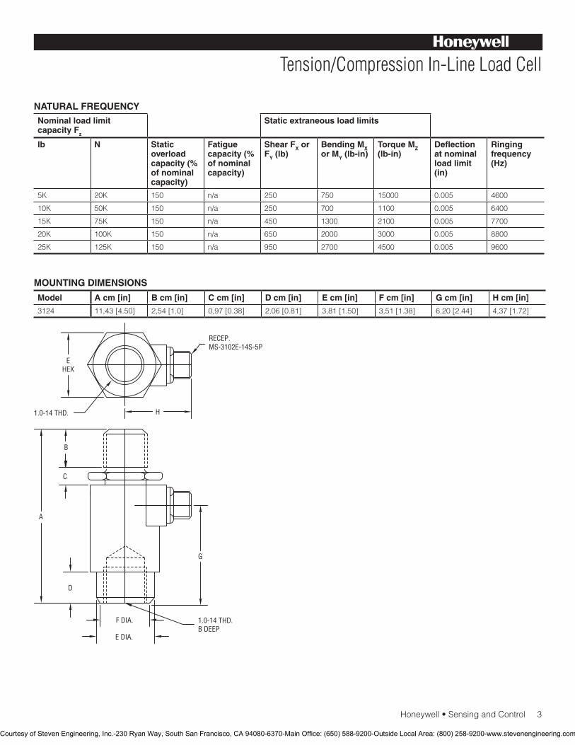
Honeywell•SensingandControl3
Tension/Compression In-Line Load Cell
NATURAL FREQUENCYNominal load limit capacity Fz
Static extraneous load limits
lb N Static overload capacity (% of nominal capacity)
Fatigue capacity (% of nominal capacity)
Shear FX or FY (lb)
Bending MX or MY (lb-in)
Torque MZ (lb-in)
Deflection at nominal load limit (in)
Ringing frequency (Hz)
5K 20K 150 n/a 250 750 15000 0.005 4600
10K 50K 150 n/a 250 700 1100 0.005 6400
15K 75K 150 n/a 450 1300 2100 0.005 7700
20K 100K 150 n/a 650 2000 3000 0.005 8800
25K 125K 150 n/a 950 2700 4500 0.005 9600
Model A cm [in] B cm [in] C cm [in] D cm [in] E cm [in] F cm [in] G cm [in] H cm [in]
3124 11,43[4.50] 2,54[1.0] 0,97[0.38] 2,06[0.81] 3,81[1.50] 3,51[1.38] 6,20[2.44] 4,37[1.72]
MOUNTING DIMENSIONS
1.0-14 THD.B DEEP
E DIA.
F DIA.
G
D
A
C
B
H
EHEX
RECEP.MS-3102E-14S-5P
1.0-14 THD.
Courtesy of Steven Engineering, Inc.-230 Ryan Way, South San Francisco, CA 94080-6370-Main Office: (650) 588-9200-Outside Local Area: (800) 258-9200-www.stevenengineering.com
SensingandControl
AutomationandControlSolutions
Honeywell
1985DouglasDriveNorth
GoldenValley,MN55422USA
+1-815-235-6847
www.honeywell.com/sensing
008661-1-EN IL50 GLO May 2008Copyright © 2008 Honeywell International Inc. All rights reserved.
Model 3124 Tension/Compression In-Line Load Cell
NOTES
1.ThisunitcalibratedtoImperial(non-Metric)units.
Warranty. Honeywellwarrantsgoodsofitsmanufactureasbeing free of defective materials and faulty workmanship. Honeywell’sstandardproductwarrantyappliesunlessagreedtootherwisebyHoneywellinwriting;pleaserefertoyourorder acknowledgement or consult your local sales office for specific warranty details. If warranted goods are returned to Honeywellduringtheperiodofcoverage,Honeywellwillrepairor replace, at its option, without charge those items it finds defective. The foregoing is buyer’s sole remedy and is in lieu of all warranties, expressed or implied, including those of merchantability and fitness for a particular purpose. In no event shall Honeywell be liable for consequential, special, or indirect damages.
While we provide application assistance personally, through our literatureandtheHoneywellwebsite,itisuptothecustomertodetermine the suitability of the product in the application.
Specifications may change without notice. The information we supply is believed to be accurate and reliable as of this printing. However,weassumenoresponsibilityforitsuse.
FormoreinformationaboutSensingandControlproducts,visitwww.honeywell.com/sensingorcall+1-815-235-6847Email inquiries to [email protected]
WARNINGPERSONAL INJURY•DONOTUSEtheseproductsassafetyoremergencystopdevicesorinanyotherapplicationwherefailureoftheproductcouldresultinpersonalinjury.
Failure to comply with these instructions could result in death or serious injury.
WARNINGMISUSE OF DOCUMENTATION•Theinformationpresentedinthiscatalogueisforreferenceonly.DONOTUSEthisdocumentasproductinstallationinformation.•Completeinstallation,operationandmaintenanceinformationisprovidedintheinstructionssuppliedwitheachproduct.
Failure to comply with these instructions could result in death or serious injury.
Courtesy of Steven Engineering, Inc.-230 Ryan Way, South San Francisco, CA 94080-6370-Main Office: (650) 588-9200-Outside Local Area: (800) 258-9200-www.stevenengineering.com
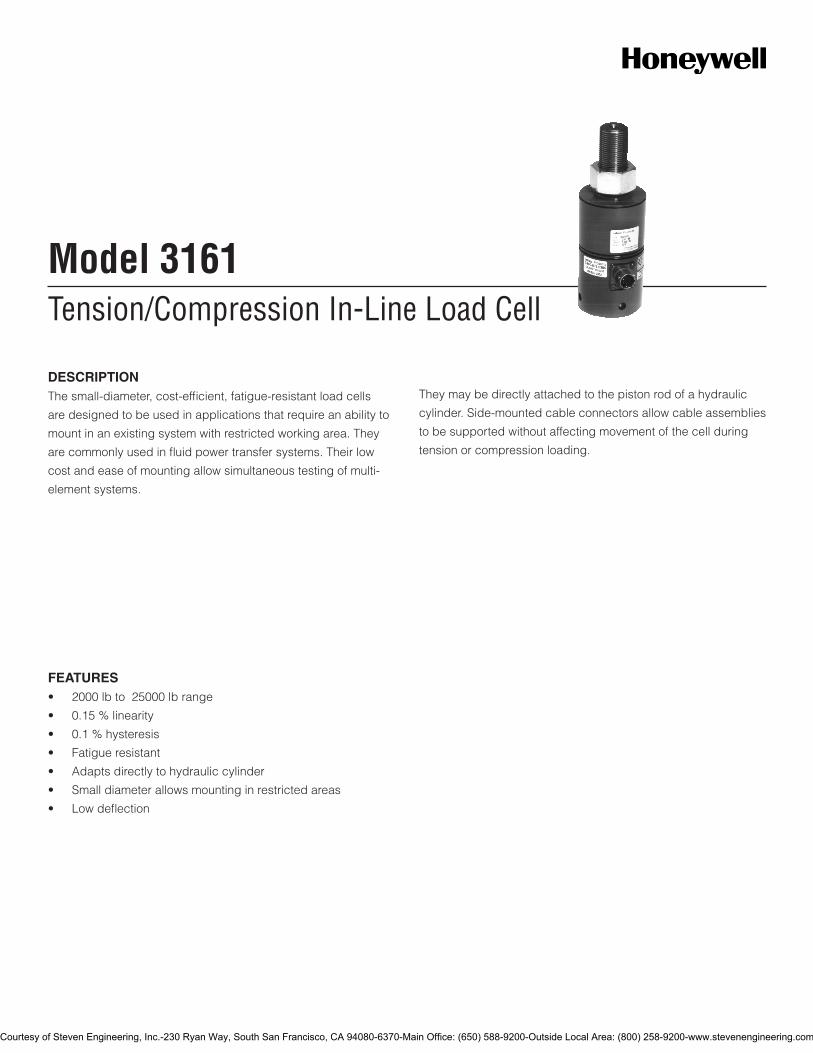
Tension/Compression In-Line Load CellModel 3161
DESCRIPTIONThe small-diameter, cost-efficient, fatigue-resistant load cells
are designed to be used in applications that require an ability to
mount in an existing system with restricted working area. They
are commonly used in fluid power transfer systems. Their low
cost and ease of mounting allow simultaneous testing of multi-
element systems.
They may be directly attached to the piston rod of a hydraulic
cylinder. Side-mounted cable connectors allow cable assemblies
to be supported without affecting movement of the cell during
tension or compression loading.
FEATURES• 2000lbto25000lbrange
• 0.15%linearity
• 0.1%hysteresis
• Fatigueresistant
• Adaptsdirectlytohydrauliccylinder
• Smalldiameterallowsmountinginrestrictedareas
• Lowdeflection
Courtesy of Steven Engineering, Inc.-230 Ryan Way, South San Francisco, CA 94080-6370-Main Office: (650) 588-9200-Outside Local Area: (800) 258-9200-www.stevenengineering.com
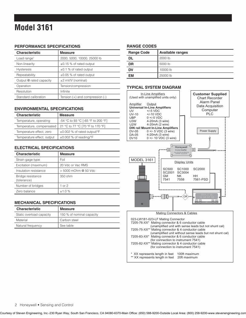
2Honeywell•SensingandControl
Model 3161
RANGE CODES
Range Code Available ranges
DL 2000lb
DR 5000lb
DV 10000lb
EM 25000lb
PERFORMANCE SPECIFICATIONS
Characteristic Measure
Loadrange1 2000,5000,10000,25000lb
Non-linearity ±0.15%ofratedoutput
Hysteresis ±0.1%ofratedoutput
Repeatability ±0.05%ofratedoutput
Output @ rated capacity ±2mV/V(nominal)
Operation Tension/compression
Resolution Infinite
Standard calibration Tension(+)andcompression(-)
ENVIRONMENTAL SPECIFICATIONS
Characteristic Measure
Temperature, operating -54°Cto93°C[-65°Fto200°F]
Temperature, compensated 21°Cto77°C[70°Fto170°F]
Temperature effect, zero ±0.002%ofratedoutput/°F
Temperature effect, output ±0.002%ofreading/°F
ELECTRICAL SPECIFICATIONS
Characteristic Measure
Strain gage type Foil
Excitation(maximum) 20VdcorVacRMS
Insulation resistance >5000mOhm@50Vdc
Bridge resistance (tolerance)
350ohm
Number of bridges 1or2
Zero balance ±1.0%
MECHANICAL SPECIFICATIONS
Characteristic Measure
Static overload capacity 150%ofnominalcapacity
Material Carbonsteel
Natural frequency See table
TYPICAL SYSTEM DIAGRAM
HoneywellIn-Line Amplifier
Output Input
Serial Number
Power Supply
Customer SuppliedChart Recorder
Alarm PanelData Acquisition
ComputerPLC
MODEL 3161
(Used with unamplified units only)
UVUV-10UBPU3WU2W
DV-05DA-05DV10
In-Line Amplifiers
AmplifierUniversal In-Line Amplifiers
DIN rail Mount In-Line Amplifiers
Output
+/-5 VDC+/-10 VDC0 +/-5 VDC4-20mA (3 wire)4-20mA (2 wire)
0 +/- 5 VDC (3 wire)4-20mA (3 wire)0 +/- 10 VDC (3 wire)
2003.1 lb.L1 L2 L3 L4
UP DOWN
VALUE CLEAR CHAN TARE
ENTERSETUP EXIT
SC500 SC1000 SC2000SC2001 SC3004GM NK HH7541 7558 7561-PSD
Display Units
Mating Connectors & Cables
OR
023-LW181-023-LF Mating Connector7205-76-XX* Mating connector & 6 conductor cable (unamplified unit with sense leads but not shunt cal)7205-75-XX** Mating connector & 4 conductor cable (unamplified unit without sense leads but not shunt cal)7205-83-XX* Mating connector & 6 conductor cable (for connection to instrument 7541)7205-82-XX** Mating connector & 4 conductor cable (for connection to instrument 7541)
* XX represents length in feet 100ft maximum** XX represents length in feet 20ft maximum
Courtesy of Steven Engineering, Inc.-230 Ryan Way, South San Francisco, CA 94080-6370-Main Office: (650) 588-9200-Outside Local Area: (800) 258-9200-www.stevenengineering.com
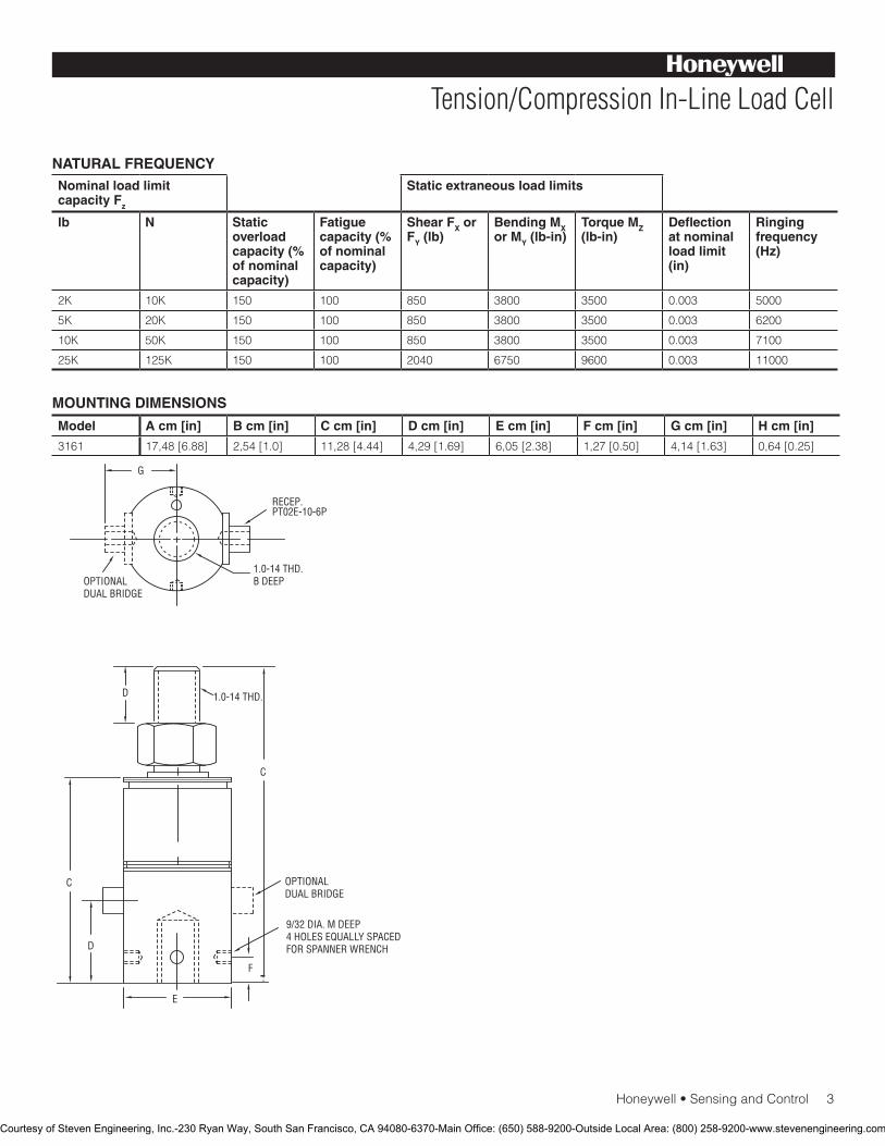
Honeywell•SensingandControl3
Tension/Compression In-Line Load Cell
NATURAL FREQUENCYNominal load limit capacity Fz
Static extraneous load limits
lb N Static overload capacity (% of nominal capacity)
Fatigue capacity (% of nominal capacity)
Shear FX or FY (lb)
Bending MX or MY (lb-in)
Torque MZ (lb-in)
Deflection at nominal load limit (in)
Ringing frequency (Hz)
2K 10K 150 100 850 3800 3500 0.003 5000
5K 20K 150 100 850 3800 3500 0.003 6200
10K 50K 150 100 850 3800 3500 0.003 7100
25K 125K 150 100 2040 6750 9600 0.003 11000
Model A cm [in] B cm [in] C cm [in] D cm [in] E cm [in] F cm [in] G cm [in] H cm [in]
3161 17,48[6.88] 2,54[1.0] 11,28[4.44] 4,29[1.69] 6,05[2.38] 1,27[0.50] 4,14[1.63] 0,64[0.25]
MOUNTING DIMENSIONS
D
D
F
C
C
G
OPTIONALDUAL BRIDGE
9/32 DIA. M DEEP4 HOLES EQUALLY SPACEDFOR SPANNER WRENCH
E
1.0-14 THD.
1.0-14 THD.B DEEP
RECEP.PT02E-10-6P
OPTIONALDUAL BRIDGE
Courtesy of Steven Engineering, Inc.-230 Ryan Way, South San Francisco, CA 94080-6370-Main Office: (650) 588-9200-Outside Local Area: (800) 258-9200-www.stevenengineering.com

SensingandControl
AutomationandControlSolutions
Honeywell
1985DouglasDriveNorth
GoldenValley,MN55422USA
+1-815-235-6847
www.honeywell.com/sensing
008660-1-EN IL50 GLO May 2008Copyright © 2008 Honeywell International Inc. All rights reserved.
Model 3161 Tension/Compression In-Line Load Cell
NOTES
1.ThisunitcalibratedtoImperial(non-Metric)units.
Warranty. Honeywellwarrantsgoodsofitsmanufactureasbeing free of defective materials and faulty workmanship. Honeywell’sstandardproductwarrantyappliesunlessagreedtootherwisebyHoneywellinwriting;pleaserefertoyourorder acknowledgement or consult your local sales office for specific warranty details. If warranted goods are returned to Honeywellduringtheperiodofcoverage,Honeywellwillrepairor replace, at its option, without charge those items it finds defective. The foregoing is buyer’s sole remedy and is in lieu of all warranties, expressed or implied, including those of merchantability and fitness for a particular purpose. In no event shall Honeywell be liable for consequential, special, or indirect damages.
While we provide application assistance personally, through our literatureandtheHoneywellwebsite,itisuptothecustomertodetermine the suitability of the product in the application.
Specifications may change without notice. The information we supply is believed to be accurate and reliable as of this printing. However,weassumenoresponsibilityforitsuse.
FormoreinformationaboutSensingandControlproducts,visitwww.honeywell.com/sensingorcall+1-815-235-6847Email inquiries to [email protected]
WARNINGPERSONAL INJURY•DONOTUSEtheseproductsassafetyoremergencystopdevicesorinanyotherapplicationwherefailureoftheproductcouldresultinpersonalinjury.
Failure to comply with these instructions could result in death or serious injury.
WARNINGMISUSE OF DOCUMENTATION•Theinformationpresentedinthiscatalogueisforreferenceonly.DONOTUSEthisdocumentasproductinstallationinformation.•Completeinstallation,operationandmaintenanceinformationisprovidedintheinstructionssuppliedwitheachproduct.
Failure to comply with these instructions could result in death or serious injury.
Courtesy of Steven Engineering, Inc.-230 Ryan Way, South San Francisco, CA 94080-6370-Main Office: (650) 588-9200-Outside Local Area: (800) 258-9200-www.stevenengineering.com
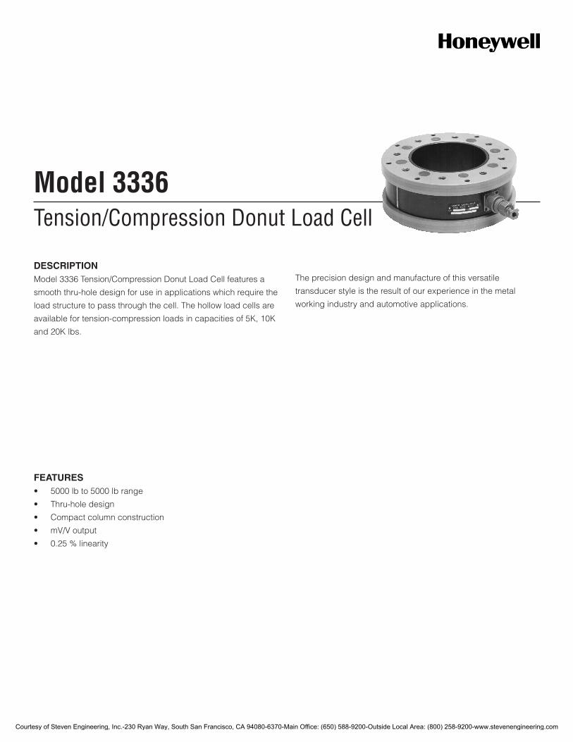
Tension/Compression Donut Load CellModel 3336
DESCRIPTIONModel 3336 Tension/Compression Donut Load Cell features a
smooth thru-hole design for use in applications which require the
load structure to pass through the cell. The hollow load cells are
available for tension-compression loads in capacities of 5K, 10K
and 20K lbs.
The precision design and manufacture of this versatile
transducer style is the result of our experience in the metal
working industry and automotive applications.
FEATURES• 5000lbto5000lbrange
• Thru-holedesign
• Compactcolumnconstruction
• mV/Voutput
• 0.25%linearity
Courtesy of Steven Engineering, Inc.-230 Ryan Way, South San Francisco, CA 94080-6370-Main Office: (650) 588-9200-Outside Local Area: (800) 258-9200-www.stevenengineering.com

2Honeywell•SensingandControl
Model 3336
PERFORMANCE SPECIFICATIONS
Characteristic Measure
Load range1 5000, 10000, 20000 lb
Non-linearity ±0.25%ofratedoutput
Hysteresis ±0.15%ofratedoutput
Repeatability ±0.15%ofratedoutput
Output @ rated capacity ±2mV/V(nominal)
Operation Tension/compression
Resolution Infinite
Standardcalibration Tension(+)andcompression(-)
ENVIRONMENTAL SPECIFICATIONS
Characteristic Measure
Temperature, operating -54 °C to 93 °C [-65 °F to 200 °F]
Temperature, compensated 21 °C to 77 °C [70 °F to 170 °F]
Temperature effect, zero ±0.002%ofratedoutput/°F
Temperature effect, output ±0.002%ofreading/°F
ELECTRICAL SPECIFICATIONS
Characteristic Measure
Straingagetype Foil
Excitation(maximum) 20VdcorVacRMS
Insulation resistance >5000mOhm@50Vdc
Bridge resistance, 5K lb 350 ohm
Bridgeresistance,(tol.)10K, 20 K lb
700 ohm
Number of bridges 1 or 2
Zero balance ±1.0%
Electrical termination MS3102E-14S-5P
MECHANICAL SPECIFICATIONS
Characteristic Measure
Staticoverloadcapacity 150%ofnominalcapacity
Material Aluminum
Natural frequency Seetable
WIRING CODES
Cable
Red (+)excitation
Black (-)excitation
Green (+)output
White (-)output
TYPICAL SYSTEM DIAGRAM
HoneywellIn-Line Amplifier
Output Input
Serial Number
Power Supply
Customer SuppliedChart Recorder
Alarm PanelData Acquisition
ComputerPLC
MODEL 3336
(Used with unamplified units only)
UVUV-10UBPU3WU2W
DV-05DA-05DV10
In-Line Amplifiers
AmplifierUniversal In-Line Amplifiers
DIN rail Mount In-Line Amplifiers
Output
+/-5 VDC+/-10 VDC0 +/-5 VDC4-20mA (3 wire)4-20mA (2 wire)
0 +/- 5 VDC (3 wire)4-20mA (3 wire)0 +/- 10 VDC (3 wire)
2003.1 lb.L1 L2 L3 L4
UP DOWN
VALUE CLEAR CHAN TARE
ENTERSETUP EXIT
SC500 SC1000 SC2000SC2001 SC3004GM NK HH7541 7558 7561-PSD
Display Units
* XX represents length in feet 100ft maximum** XX represents length in feet 20ft maximum
Mating Connectors & Cables
OR
064-LW13621 Mating connector7200-76-XX* Mating connector and six conductor cable (unamplified unit with sense leads but not shunt cal)7200-75-XX** Mating connector (MS - 5 pin) and four conductor cable (unamplified sensor without sense leads)7200-111-XX** Mating connector ( MS – 5 pin ) & 6 conductor cable for connection to 7541 7200-110-XX** Mating connector ( MS – 5 pin ) & 4 conductor cable for connection to 7541
Courtesy of Steven Engineering, Inc.-230 Ryan Way, South San Francisco, CA 94080-6370-Main Office: (650) 588-9200-Outside Local Area: (800) 258-9200-www.stevenengineering.com
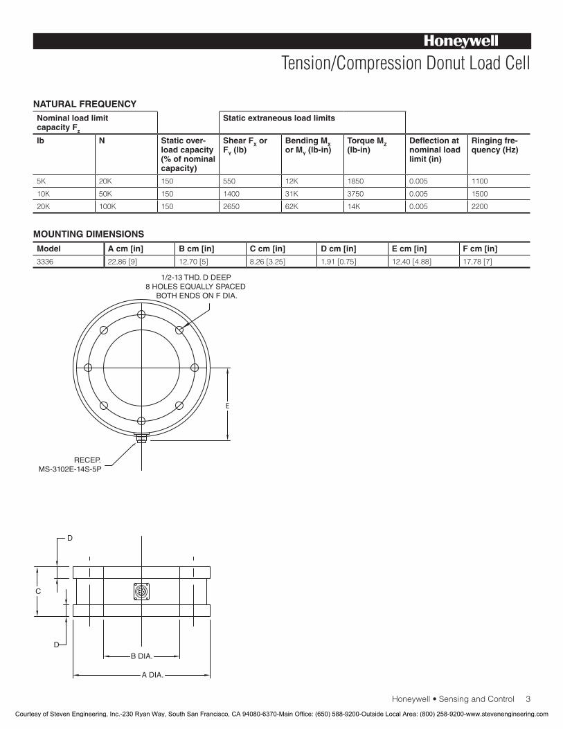
Honeywell•SensingandControl3
Tension/Compression Donut Load Cell
NATURAL FREQUENCYNominal load limit capacity Fz
Static extraneous load limits
lb N Static over-load capacity (% of nominal capacity)
Shear FX or FY (lb)
Bending MX or MY (lb-in)
Torque MZ (lb-in)
Deflection at nominal load limit (in)
Ringing fre-quency (Hz)
5K 20K 150 550 12K 1850 0.005 1100
10K 50K 150 1400 31K 3750 0.005 1500
20K 100K 150 2650 62K 14K 0.005 2200
Model A cm [in] B cm [in] C cm [in] D cm [in] E cm [in] F cm [in]
3336 22,86 [9] 12,70 [5] 8,26 [3.25] 1,91 [0.75] 12,40 [4.88] 17,78 [7]
MOUNTING DIMENSIONS
Courtesy of Steven Engineering, Inc.-230 Ryan Way, South San Francisco, CA 94080-6370-Main Office: (650) 588-9200-Outside Local Area: (800) 258-9200-www.stevenengineering.com
SensingandControl
AutomationandControlSolutions
Honeywell
1985 Douglas Drive North
GoldenValley,MN55422USA
+1-815-235-6847
www.honeywell.com/sensing
008652-2-EN IL50 GLO December 2008Copyright © 2008 Honeywell International Inc. All rights reserved.
Model 3336 Tension/Compression Donut Load Cell
NOTES
1. ThisunitcalibratedtoImperial(non-Metric)units.
Warranty. Honeywell warrants goods of its manufacture as being free of defective materials and faulty workmanship. Honeywell’s standard product warranty applies unless agreed to otherwise by Honeywell in writing; please refer to your order acknowledgement or consult your local sales office for specific warranty details. If warranted goods are returned to Honeywell during the period of coverage, Honeywell will repair or replace, at its option, without charge those items it finds defective. The foregoing is buyer’s sole remedy and is in lieu of all warranties, expressed or implied, including those of merchantability and fitness for a particular purpose. In no event shall Honeywell be liable for consequential, special, or indirect damages.
While we provide application assistance personally, through our literature and the Honeywell web site, it is up to the customer to determine the suitability of the product in the application.
Specificationsmaychangewithoutnotice.Theinformationwesupply is believed to be accurate and reliable as of this printing. However, we assume no responsibility for its use.
FormoreinformationaboutSensingandControlproducts,visitwww.honeywell.com/sensingorcall+1-815-235-6847Email inquiries to [email protected]
WARNINGPERSONAL INJURY•DONOTUSEtheseproductsassafetyoremergencystopdevicesorinanyotherapplicationwherefailureoftheproductcouldresultinpersonalinjury.
Failure to comply with these instructions could result in death or serious injury.
WARNINGMISUSE OF DOCUMENTATION•Theinformationpresentedinthiscatalogueisforreferenceonly.DONOTUSEthisdocumentasproductinstallationinformation.•Completeinstallation,operationandmaintenanceinformationisprovidedintheinstructionssuppliedwitheachproduct.
Failure to comply with these instructions could result in death or serious injury.
Courtesy of Steven Engineering, Inc.-230 Ryan Way, South San Francisco, CA 94080-6370-Main Office: (650) 588-9200-Outside Local Area: (800) 258-9200-www.stevenengineering.com
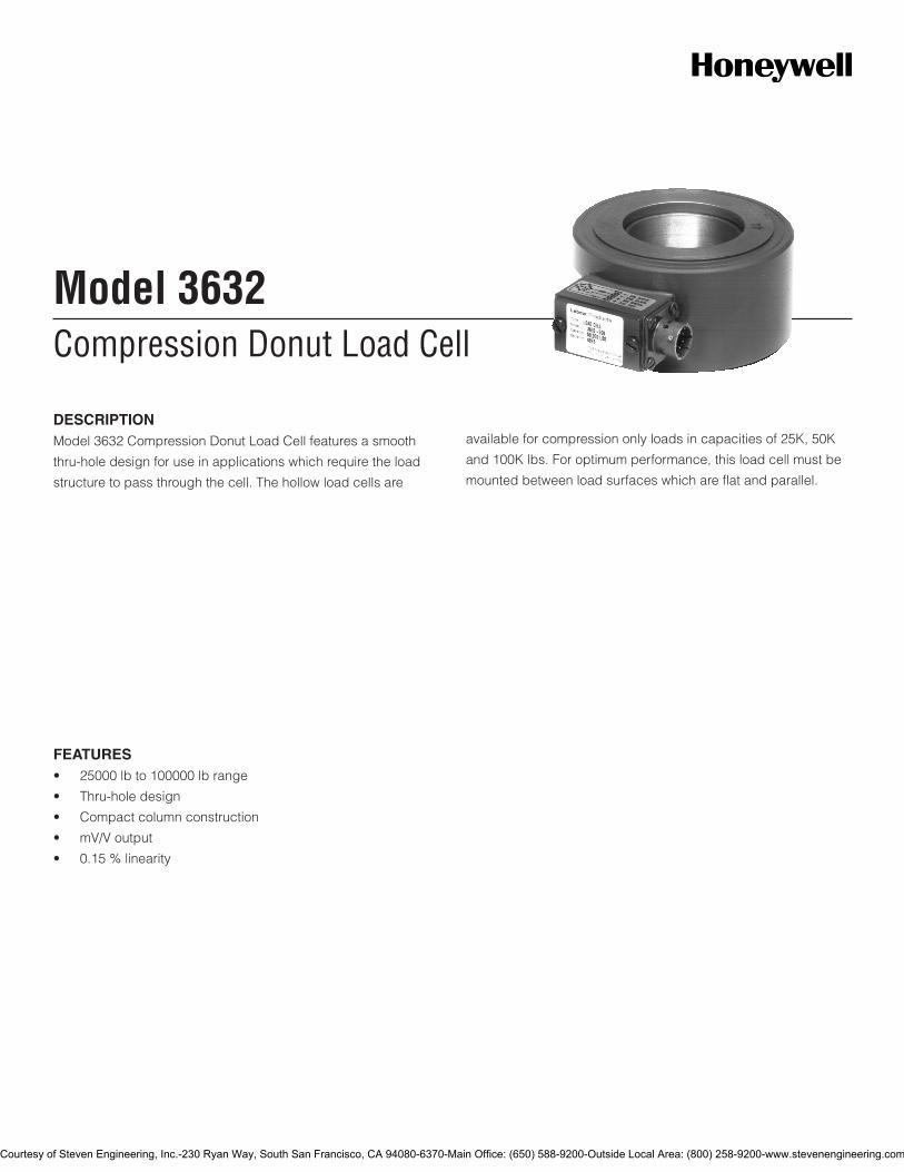
Compression Donut Load CellModel 3632
DESCRIPTIONModel 3632 Compression Donut Load Cell features a smooth
thru-hole design for use in applications which require the load
structure to pass through the cell. The hollow load cells are
available for compression only loads in capacities of 25K, 50K
and 100K lbs. For optimum performance, this load cell must be
mounted between load surfaces which are flat and parallel.
FEATURES• 25000lbto100000lbrange
• Thru-holedesign
• Compactcolumnconstruction
• mV/Voutput
• 0.15%linearity
Courtesy of Steven Engineering, Inc.-230 Ryan Way, South San Francisco, CA 94080-6370-Main Office: (650) 588-9200-Outside Local Area: (800) 258-9200-www.stevenengineering.com
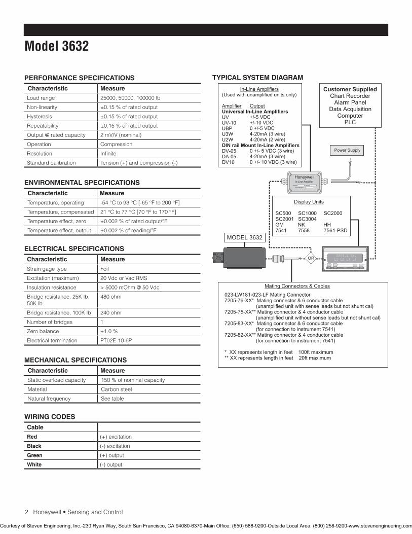
2Honeywell•SensingandControl
Model 3632
PERFORMANCE SPECIFICATIONS
Characteristic Measure
Load range1 25000, 50000, 100000 lb
Non-linearity ±0.15%ofratedoutput
Hysteresis ±0.15%ofratedoutput
Repeatability ±0.15%ofratedoutput
Output @ rated capacity 2mV/V(nominal)
Operation Compression
Resolution Infinite
Standardcalibration Tension(+)andcompression(-)
ENVIRONMENTAL SPECIFICATIONS
Characteristic Measure
Temperature, operating -54 °C to 93 °C [-65 °F to 200 °F]
Temperature, compensated 21 °C to 77 °C [70 °F to 170 °F]
Temperature effect, zero ±0.002%ofratedoutput/°F
Temperature effect, output ±0.002%ofreading/°F
ELECTRICAL SPECIFICATIONS
Characteristic Measure
Straingagetype Foil
Excitation(maximum) 20VdcorVacRMS
Insulation resistance >5000mOhm@50Vdc
Bridge resistance, 25K lb, 50K lb
480 ohm
Bridge resistance, 100K lb 240 ohm
Number of bridges 1
Zero balance ±1.0%
Electrical termination PT02E-10-6P
MECHANICAL SPECIFICATIONS
Characteristic Measure
Staticoverloadcapacity 150%ofnominalcapacity
Material Carbon steel
Natural frequency Seetable
WIRING CODES
Cable
Red (+)excitation
Black (-)excitation
Green (+)output
White (-)output
TYPICAL SYSTEM DIAGRAM
HoneywellIn-Line Amplifier
Output Input
Serial Number
Power Supply
Customer SuppliedChart Recorder
Alarm PanelData Acquisition
ComputerPLC
MODEL 3632
(Used with unamplified units only)
UVUV-10UBPU3WU2W
DV-05DA-05DV10
In-Line Amplifiers
AmplifierUniversal In-Line Amplifiers
DIN rail Mount In-Line Amplifiers
Output
+/-5 VDC+/-10 VDC0 +/-5 VDC4-20mA (3 wire)4-20mA (2 wire)
0 +/- 5 VDC (3 wire)4-20mA (3 wire)0 +/- 10 VDC (3 wire)
2003.1 lb.L1 L2 L3 L4
UP DOWN
VALUE CLEAR CHAN TARE
ENTERSETUP EXIT
SC500 SC1000 SC2000SC2001 SC3004GM NK HH7541 7558 7561-PSD
Display Units
Mating Connectors & Cables
OR
023-LW181-023-LF Mating Connector7205-76-XX* Mating connector & 6 conductor cable (unamplified unit with sense leads but not shunt cal)7205-75-XX** Mating connector & 4 conductor cable (unamplified unit without sense leads but not shunt cal)7205-83-XX* Mating connector & 6 conductor cable (for connection to instrument 7541)7205-82-XX** Mating connector & 4 conductor cable (for connection to instrument 7541)
* XX represents length in feet 100ft maximum** XX represents length in feet 20ft maximum
Courtesy of Steven Engineering, Inc.-230 Ryan Way, South San Francisco, CA 94080-6370-Main Office: (650) 588-9200-Outside Local Area: (800) 258-9200-www.stevenengineering.com
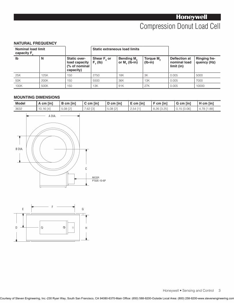
Honeywell•SensingandControl3
Compression Donut Load Cell
NATURAL FREQUENCYNominal load limit capacity Fz
Static extraneous load limits
lb N Static over-load capacity (% of nominal capacity)
Shear FX or FY (lb)
Bending MX or MY (lb-in)
Torque MZ (lb-in)
Deflection at nominal load limit (in)
Ringing fre-quency (Hz)
25K 125K 150 2750 18K 3K 0.005 5000
50K 200K 150 5500 36K 13K 0.005 7000
100K 500K 150 13K 91K 27K 0.005 10000
Model A cm [in] B cm [in] C cm [in] D cm [in] E cm [in] F cm [in] G cm [in] H cm [in]
3632 10,16 [4] 5,08 [2] 7,62 [3] 5,08 [2] 2,54 [1] 8,26 [3.25] 0,15 [0.06] 4,78 [1.88]
MOUNTING DIMENSIONS
B DIA.
H
G
D
E
C
A DIA.
F
RECEP.PT02E-10-6P
Courtesy of Steven Engineering, Inc.-230 Ryan Way, South San Francisco, CA 94080-6370-Main Office: (650) 588-9200-Outside Local Area: (800) 258-9200-www.stevenengineering.com
SensingandControl
AutomationandControlSolutions
Honeywell
1985 Douglas Drive North
GoldenValley,MN55422USA
+1-815-235-6847
www.honeywell.com/sensing
008651-1-EN IL50 GLO May 2008Copyright © 2008 Honeywell International Inc. All rights reserved.
Model 3632 Compression Donut Load Cell
NOTES
1. ThisunitcalibratedtoImperial(non-Metric)units.
Warranty. Honeywell warrants goods of its manufacture as being free of defective materials and faulty workmanship. Honeywell’s standard product warranty applies unless agreed to otherwise by Honeywell in writing; please refer to your order acknowledgement or consult your local sales office for specific warranty details. If warranted goods are returned to Honeywell during the period of coverage, Honeywell will repair or replace, at its option, without charge those items it finds defective. The foregoing is buyer’s sole remedy and is in lieu of all warranties, expressed or implied, including those of merchantability and fitness for a particular purpose. In no event shall Honeywell be liable for consequential, special, or indirect damages.
While we provide application assistance personally, through our literature and the Honeywell web site, it is up to the customer to determine the suitability of the product in the application.
Specificationsmaychangewithoutnotice.Theinformationwesupply is believed to be accurate and reliable as of this printing. However, we assume no responsibility for its use.
FormoreinformationaboutSensingandControlproducts,visitwww.honeywell.com/sensingorcall+1-815-235-6847Email inquiries to [email protected]
WARNINGPERSONAL INJURY•DONOTUSEtheseproductsassafetyoremergencystopdevicesorinanyotherapplicationwherefailureoftheproductcouldresultinpersonalinjury.
Failure to comply with these instructions could result in death or serious injury.
WARNINGMISUSE OF DOCUMENTATION•Theinformationpresentedinthiscatalogueisforreferenceonly.DONOTUSEthisdocumentasproductinstallationinformation.•Completeinstallation,operationandmaintenanceinformationisprovidedintheinstructionssuppliedwitheachproduct.
Failure to comply with these instructions could result in death or serious injury.
Courtesy of Steven Engineering, Inc.-230 Ryan Way, South San Francisco, CA 94080-6370-Main Office: (650) 588-9200-Outside Local Area: (800) 258-9200-www.stevenengineering.com
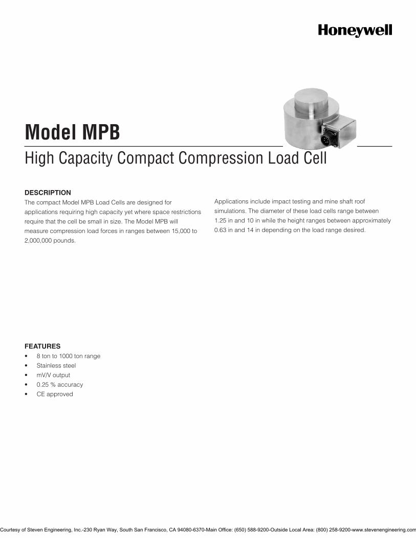
High Capacity Compact Compression Load CellModel MPB
DESCRIPTIONThe compact Model MPB Load Cells are designed for
applications requiring high capacity yet where space restrictions
require that the cell be small in size. The Model MPB will
measure compression load forces in ranges between 15,000 to
2,000,000 pounds.
Applications include impact testing and mine shaft roof
simulations. The diameter of these load cells range between
1.25 in and 10 in while the height ranges between approximately
0.63 in and 14 in depending on the load range desired.
FEATURES• 8tonto1000tonrange
• Stainlesssteel
• mV/Voutput
• 0.25%accuracy
• CEapproved
Courtesy of Steven Engineering, Inc.-230 Ryan Way, South San Francisco, CA 94080-6370-Main Office: (650) 588-9200-Outside Local Area: (800) 258-9200-www.stevenengineering.com
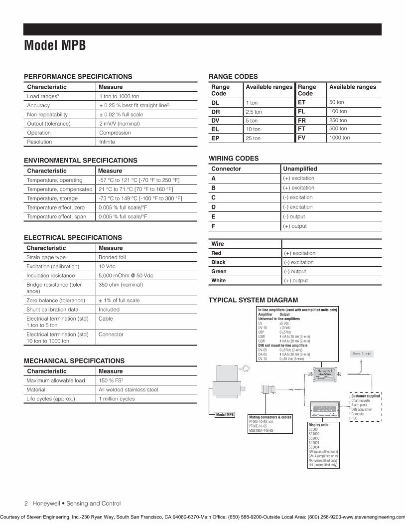
2Honeywell•SensingandControl
Model MPB
PERFORMANCE SPECIFICATIONS
Characteristic Measure
Load ranges9 1 ton to 1000 ton
Accuracy ±0.25%bestfitstraightline2
Non-repeatability ±0.02%fullscale
Output (tolerance) 2mV/V(nominal)
Operation Compression
Resolution Infinite
ELECTRICAL SPECIFICATIONS
Characteristic Measure
Straingagetype Bonded foil
Excitation(calibration) 10Vdc
Insulation resistance 5,000mOhm@50Vdc
Bridge resistance (toler-ance)
350 ohm (nominal)
Zero balance (tolerance) ±1%offullscale
Shuntcalibrationdata Included
Electricaltermination(std)1 ton to 5 ton
Cable
Electricaltermination(std)10 ton to 1000 ton
Connector
MECHANICAL SPECIFICATIONS
Characteristic Measure
Maximum allowable load 150%FS3
Material All welded stainless steel
Life cycles (approx.) 1 million cycles
WIRING CODES
Connector Unamplified
A (+) excitation
B (+) excitation
C (-) excitation
D (-) excitation
E (-) output
F (+) output
Wire
Red (+) excitation
Black (-) excitation
Green (-) output
White (+) output
ENVIRONMENTAL SPECIFICATIONS
Characteristic Measure
Temperature, operating -57°Cto121°C[-70°Fto250°F]
Temperature, compensated 21°Cto71°C[70°Fto160°F]
Temperature, storage -73°Cto149°C[-100°Fto300°F]
Temperature effect, zero 0.005%fullscale/°F
Temperature effect, span 0.005%fullscale/°F
RANGE CODES
Range Code
Available ranges Range Code
Available ranges
DL 1 ton ET 50 ton
DR 2.5 ton FL 100 ton
DV 5 ton FR 250 ton
EL 10 ton FT 500 ton
EP 25 ton FV 1000 ton
TYPICAL SYSTEM DIAGRAM
Courtesy of Steven Engineering, Inc.-230 Ryan Way, South San Francisco, CA 94080-6370-Main Office: (650) 588-9200-Outside Local Area: (800) 258-9200-www.stevenengineering.com
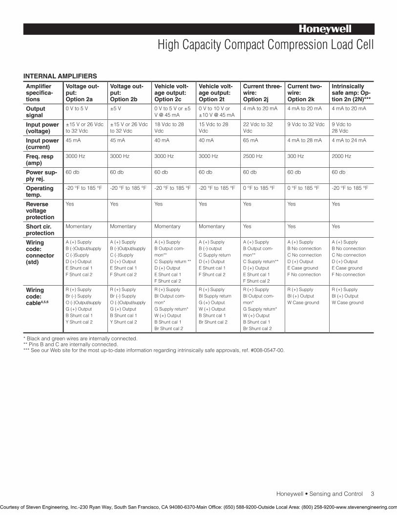
Honeywell•SensingandControl3
High Capacity Compact Compression Load Cell
INTERNAL AMPLIFIERS
Amplifier specifica-tions
Voltage out-put: Option 2a
Voltage out-put: Option 2b
Vehicle volt-age output: Option 2c
Vehicle volt-age output: Option 2t
Current three-wire: Option 2j
Current two-wire: Option 2k
Intrinsically safe amp: Op-tion 2n (2N)***
Output signal
0Vto5V ±5V 0Vto5Vor±5V@45mA
0Vto10Vor±10V@45mA
4 mA to 20 mA 4 mA to 20 mA 4 mA to 20 mA
Input power (voltage)
±15Vor26Vdcto32Vdc
±15Vor26Vdcto32Vdc
18Vdcto28Vdc
15Vdcto28Vdc
22Vdcto32Vdc
9Vdcto32Vdc 9Vdcto 28Vdc
Input power (current)
45 mA 45 mA 40 mA 40 mA 65 mA 4mAto28mA 4 mA to 24 mA
Freq. resp (amp)
3000 Hz 3000 Hz 3000 Hz 3000 Hz 2500 Hz 300 Hz 2000 Hz
Power sup-ply rej.
60 db 60 db 60 db 60 db 60 db 60 db 60 db
Operating temp.
-20°Fto185°F -20°Fto185°F -20°Fto185°F -20°Fto185°F 0°Fto185°F 0°Fto185°F -20°Fto185°F
Reverse voltage protection
Yes Yes Yes Yes Yes Yes Yes
Short cir. protection
Momentary Momentary Momentary Momentary Yes Yes Yes
Wiring code: connector (std)
A(+)SupplyB(-)Output/supplyC(-)SupplyD (+) OutputEShuntcal1FShuntcal2
A(+)SupplyB(-)Output/supplyC(-)SupplyD (+) OutputEShuntcal1FShuntcal2
A(+)SupplyB Output com-mon**CSupplyreturn**D (+) OutputEShuntcal1FShuntcal2
A(+)SupplyB (-) outputCSupplyreturnD (+) OutputEShuntcal1FShuntcal2
A(+)SupplyB Output com-mon**CSupplyreturn**D (+) OutputEShuntcal1FShuntcal2
A(+)SupplyB No connectionC No connectionD (+) OutputECasegroundFNoconnection
A(+)SupplyB No connectionC No connectionD (+) OutputECasegroundFNoconnection
Wiring code: cable4,5,6
R(+)SupplyBr(-)SupplyO(-)Output/supplyG (+) OutputBShuntcal1YShuntcal2
R(+)SupplyBr(-)SupplyO(-)Output/supplyG (+) OutputBShuntcal1YShuntcal2
R(+)SupplyBl Output com-mon*GSupplyreturn*W (+) OutputBShuntcal1BrShuntcal2
R(+)SupplyBlSupplyreturnG (+) OutputW (+) OutputBShuntcal1BrShuntcal2
R(+)SupplyBl Output com-mon*GSupplyreturn*W (+) OutputBShuntcal1BrShuntcal2
R(+)SupplyBl (+) OutputW Case ground
R(+)SupplyBl (+) OutputW Case ground
* Black and green wires are internally connected.** Pins B and C are internally connected.***SeeourWebsiteforthemostup-to-dateinformationregardingintrinsicallysafeapprovals,ref.#008-0547-00.
Courtesy of Steven Engineering, Inc.-230 Ryan Way, South San Francisco, CA 94080-6370-Main Office: (650) 588-9200-Outside Local Area: (800) 258-9200-www.stevenengineering.com
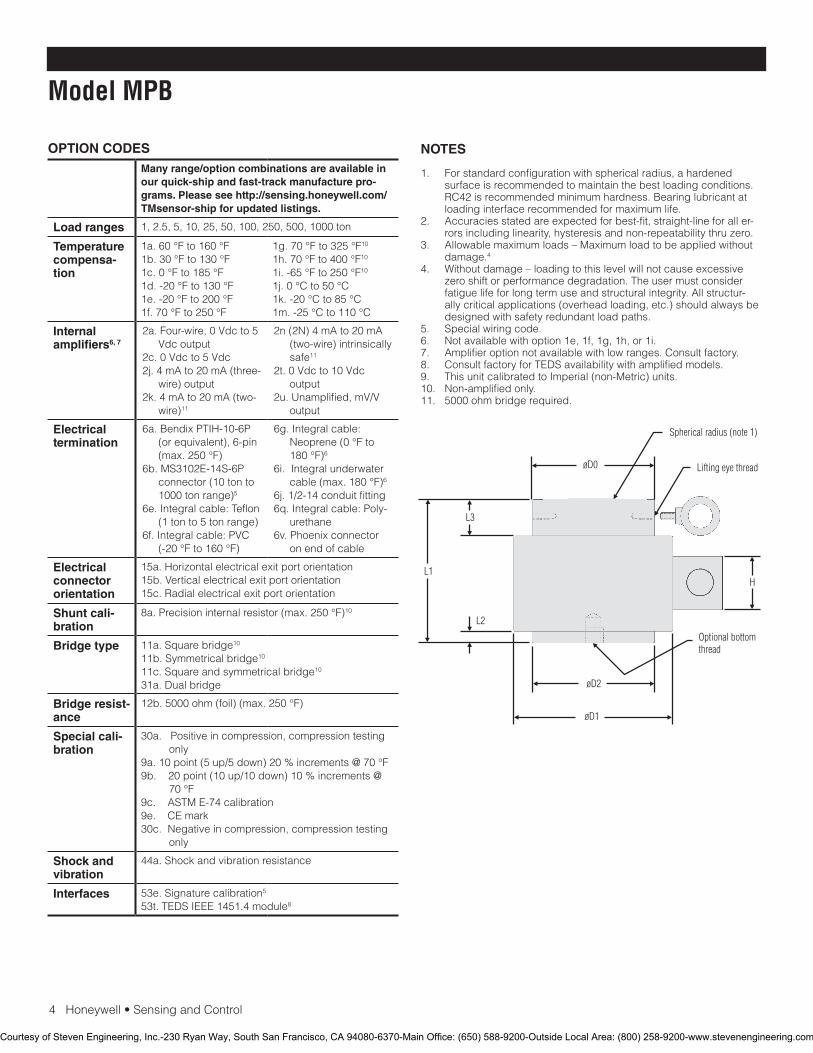
4Honeywell•SensingandControl
Model MPB
NOTES
1. Forstandardconfigurationwithsphericalradius,ahardenedsurface is recommended to maintain the best loading conditions. RC42 is recommended minimum hardness. Bearing lubricant at loading interface recommended for maximum life.
2. Accuraciesstatedareexpectedforbest-fit,straight-lineforaller-rors including linearity, hysteresis and non-repeatability thru zero.
3. Allowable maximum loads – Maximum load to be applied without damage.4
4. Withoutdamage–loadingtothislevelwillnotcauseexcessivezero shift or performance degradation. The user must consider fatigue life for long term use and structural integrity. All structur-allycriticalapplications(overheadloading,etc.)shouldalwaysbedesigned with safety redundant load paths.
5. Specialwiringcode.6. Notavailablewithoption1e,1f,1g,1h,or1i.7. Amplifieroptionnotavailablewithlowranges.Consultfactory.8. ConsultfactoryforTEDSavailabilitywithamplifiedmodels.9. This unit calibrated to Imperial (non-Metric) units.10. Non-amplifiedonly.11. 5000 ohm bridge required.
OPTION CODESMany range/option combinations are available in our quick-ship and fast-track manufacture pro-grams. Please see http://sensing.honeywell.com/TMsensor-ship for updated listings.
Load ranges 1, 2.5, 5, 10, 25, 50, 100, 250, 500, 1000 ton
Temperature compensa-tion
1a.60°Fto160°F1b.30°Fto130°F1c.0°Fto185°F1d.-20°Fto130°F1e.-20°Fto200°F1f.70°Fto250°F
1g.70°Fto325°F10
1h.70°Fto400°F10
1i.-65°Fto250°F10
1j. 0 °C to 50 °C1k.-20°Cto85°C1m. -25 °C to 110 °C
Internal amplifiers6, 7
2a.Four-wire,0Vdcto5Vdcoutput
2c.0Vdcto5Vdc2j. 4 mA to 20 mA (three-
wire) output2k. 4 mA to 20 mA (two-
wire)11
2n (2N) 4 mA to 20 mA (two-wire) intrinsically safe11
2t.0Vdcto10Vdcoutput
2u.Unamplified,mV/Voutput
Electrical termination
6a. Bendix PTIH-10-6P (orequivalent),6-pin(max.250°F)
6b.MS3102E-14S-6Pconnector (10 ton to 1000 ton range)5
6e. Integral cable: Teflon (1 ton to 5 ton range)
6f.Integralcable:PVC(-20°Fto160°F)
6g. Integral cable: Neoprene(0°Fto180°F)6
6i. Integral underwater cable(max.180°F)6
6j.1/2-14conduitfitting6q. Integral cable: Poly-
urethane6v.Phoenixconnector
on end of cable
Electrical connector orientation
15a. Horizontal electrical exit port orientation15b.Verticalelectricalexitportorientation15c. Radial electrical exit port orientation
Shunt cali-bration
8a.Precisioninternalresistor(max.250°F)10
Bridge type 11a.Squarebridge10
11b.Symmetricalbridge10 11c.Squareandsymmetricalbridge10 31a. Dual bridge
Bridge resist-ance
12b.5000ohm(foil)(max.250°F)
Special cali-bration
30a.Positiveincompression,compressiontestingonly
9a.10point(5up/5down)20%increments@70°F9b.20point(10up/10down)10%increments@
70°F9c.ASTME-74calibration9e.CEmark30c.Negativeincompression,compressiontesting
only
Shock and vibration
44a.Shockandvibrationresistance
Interfaces 53e.Signaturecalibration5
53t.TEDSIEEE1451.4module8
Courtesy of Steven Engineering, Inc.-230 Ryan Way, South San Francisco, CA 94080-6370-Main Office: (650) 588-9200-Outside Local Area: (800) 258-9200-www.stevenengineering.com
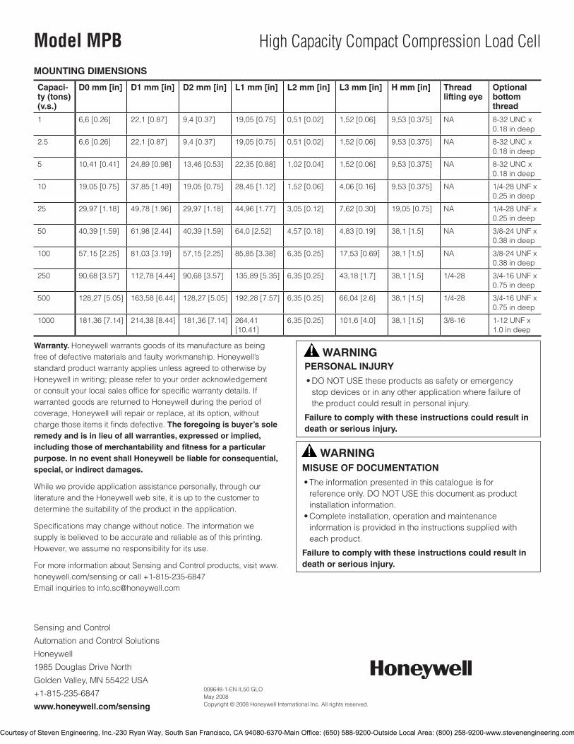
SensingandControl
AutomationandControlSolutions
Honeywell
1985DouglasDriveNorth
GoldenValley,MN55422USA
+1-815-235-6847
www.honeywell.com/sensing
008648-1-EN IL50 GLO May 2008Copyright © 2008 Honeywell International Inc. All rights reserved.
Model MPB High Capacity Compact Compression Load Cell
Warranty. Honeywell warrants goods of its manufacture as being freeofdefectivematerialsandfaultyworkmanship.Honeywell’sstandard product warranty applies unless agreed to otherwise by Honeywell in writing; please refer to your order acknowledgement orconsultyourlocalsalesofficeforspecificwarrantydetails.Ifwarranted goods are returned to Honeywell during the period of coverage,Honeywellwillrepairorreplace,atitsoption,withoutchargethoseitemsitfindsdefective.The foregoing is buyer’s sole remedy and is in lieu of all warranties, expressed or implied, including those of merchantability and fitness for a particular purpose. In no event shall Honeywell be liable for consequential, special, or indirect damages.
Whileweprovideapplicationassistancepersonally,throughourliterature and the Honeywell web site, it is up to the customer to determine the suitability of the product in the application.
Specificationsmaychangewithoutnotice.Theinformationwesupplyisbelievedtobeaccurateandreliableasofthisprinting.However,weassumenoresponsibilityforitsuse.
FormoreinformationaboutSensingandControlproducts,visitwww.honeywell.com/sensingorcall+1-815-235-6847Emailinquiriestoinfo.sc@honeywell.com
WARNINGPERSONAL INJURY•DONOTUSEtheseproductsassafetyoremergencystopdevicesorinanyotherapplicationwherefailureoftheproductcouldresultinpersonalinjury.
Failure to comply with these instructions could result in death or serious injury.
WARNINGMISUSE OF DOCUMENTATION•Theinformationpresentedinthiscatalogueisforreferenceonly.DONOTUSEthisdocumentasproductinstallationinformation.•Completeinstallation,operationandmaintenanceinformationisprovidedintheinstructionssuppliedwitheachproduct.
Failure to comply with these instructions could result in death or serious injury.
MOUNTING DIMENSIONS
Capaci-ty (tons) (v.s.)
D0 mm [in] D1 mm [in] D2 mm [in] L1 mm [in] L2 mm [in] L3 mm [in] H mm [in] Thread lifting eye
Optional bottom thread
1 6,6[0.26] 22,1[0.87] 9,4[0.37] 19,05[0.75] 0,51[0.02] 1,52[0.06] 9,53[0.375] NA 8-32UNCx0.18indeep
2.5 6,6[0.26] 22,1[0.87] 9,4[0.37] 19,05[0.75] 0,51[0.02] 1,52[0.06] 9,53[0.375] NA 8-32UNCx0.18indeep
5 10,41[0.41] 24,89[0.98] 13,46[0.53] 22,35[0.88] 1,02[0.04] 1,52[0.06] 9,53[0.375] NA 8-32UNCx0.18indeep
10 19,05[0.75] 37,85[1.49] 19,05[0.75] 28,45[1.12] 1,52[0.06] 4,06[0.16] 9,53[0.375] NA 1/4-28UNFx0.25 in deep
25 29,97[1.18] 49,78[1.96] 29,97[1.18] 44,96[1.77] 3,05[0.12] 7,62[0.30] 19,05[0.75] NA 1/4-28UNFx0.25 in deep
50 40,39[1.59] 61,98[2.44] 40,39[1.59] 64,0[2.52] 4,57[0.18] 4,83[0.19] 38,1[1.5] NA 3/8-24UNFx0.38indeep
100 57,15[2.25] 81,03[3.19] 57,15[2.25] 85,85[3.38] 6,35[0.25] 17,53[0.69] 38,1[1.5] NA 3/8-24UNFx0.38indeep
250 90,68[3.57] 112,78[4.44] 90,68[3.57] 135,89[5.35] 6,35[0.25] 43,18[1.7] 38,1[1.5] 1/4-28 3/4-16UNFx0.75 in deep
500 128,27[5.05] 163,58[6.44] 128,27[5.05] 192,28[7.57] 6,35[0.25] 66,04[2.6] 38,1[1.5] 1/4-28 3/4-16UNFx0.75 in deep
1000 181,36[7.14] 214,38[8.44] 181,36[7.14] 264,41 [10.41]
6,35[0.25] 101,6[4.0] 38,1[1.5] 3/8-16 1-12UNFx1.0 in deep
Courtesy of Steven Engineering, Inc.-230 Ryan Way, South San Francisco, CA 94080-6370-Main Office: (650) 588-9200-Outside Local Area: (800) 258-9200-www.stevenengineering.com
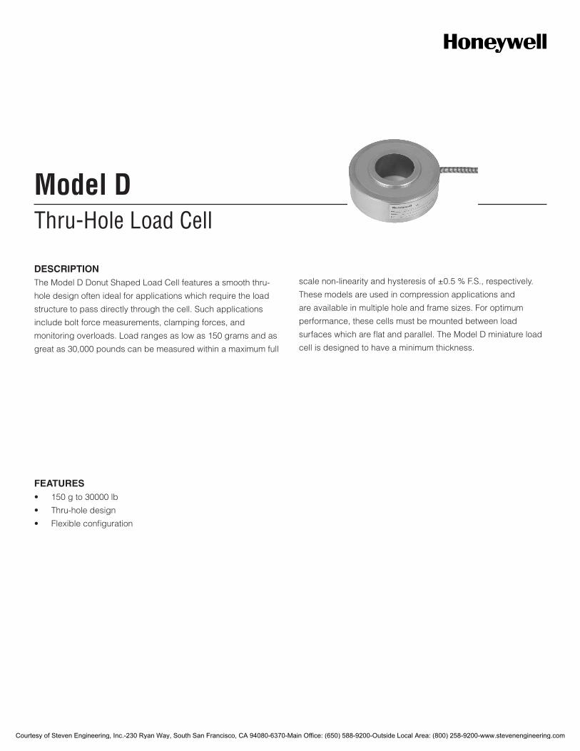
Thru-Hole Load CellModel D
DESCRIPTIONThe Model D Donut Shaped Load Cell features a smooth thru-
hole design often ideal for applications which require the load
structure to pass directly through the cell. Such applications
include bolt force measurements, clamping forces, and
monitoring overloads. Load ranges as low as 150 grams and as
great as 30,000 pounds can be measured within a maximum full
scale non-linearity and hysteresis of ±0.5 % F.S., respectively.
These models are used in compression applications and
are available in multiple hole and frame sizes. For optimum
performance, these cells must be mounted between load
surfaces which are flat and parallel. The Model D miniature load
cell is designed to have a minimum thickness.
FEATURES• 150gto30000lb
• Thru-holedesign
• Flexibleconfiguration
Courtesy of Steven Engineering, Inc.-230 Ryan Way, South San Francisco, CA 94080-6370-Main Office: (650) 588-9200-Outside Local Area: (800) 258-9200-www.stevenengineering.com
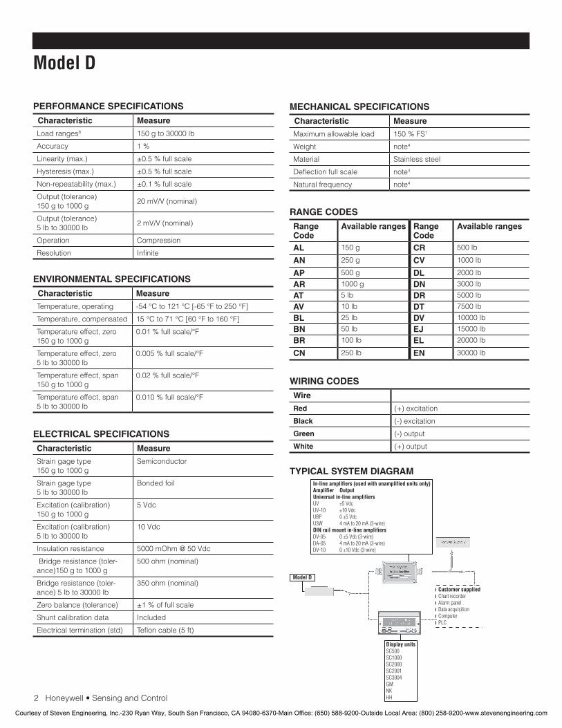
2Honeywell•SensingandControl
Model D
PERFORMANCE SPECIFICATIONS
Characteristic Measure
Load ranges8 150 g to 30000 lb
Accuracy 1 %
Linearity (max.) ±0.5 % full scale
Hysteresis (max.) ±0.5 % full scale
Non-repeatability (max.) ±0.1 % full scale
Output (tolerance) 150 g to 1000 g
20 mV/V (nominal)
Output (tolerance) 5 lb to 30000 lb
2 mV/V (nominal)
Operation Compression
Resolution Infinite
ELECTRICAL SPECIFICATIONS
Characteristic Measure
Strain gage type150 g to 1000 g
Semiconductor
Strain gage type5 lb to 30000 lb
Bonded foil
Excitation (calibration) 150 g to 1000 g
5 Vdc
Excitation (calibration)5 lb to 30000 lb
10 Vdc
Insulation resistance 5000 mOhm @ 50 Vdc
Bridge resistance (toler-ance)150 g to 1000 g
500 ohm (nominal)
Bridge resistance (toler-ance) 5 lb to 30000 lb
350 ohm (nominal)
Zero balance (tolerance) ±1 % of full scale
Shunt calibration data Included
Electrical termination (std) Teflon cable (5 ft)
MECHANICAL SPECIFICATIONS
Characteristic Measure
Maximum allowable load 150 % FS1
Weight note4
Material Stainless steel
Deflection full scale note4
Natural frequency note4
WIRING CODES
Wire
Red (+) excitation
Black (-) excitation
Green (-) output
White (+) output
ENVIRONMENTAL SPECIFICATIONS
Characteristic Measure
Temperature, operating -54 °C to 121 °C [-65 °F to 250 °F]
Temperature, compensated 15 °C to 71 °C [60 °F to 160 °F]
Temperature effect, zero 150 g to 1000 g
0.01 % full scale/°F
Temperature effect, zero 5 lb to 30000 lb
0.005 % full scale/°F
Temperature effect, span150 g to 1000 g
0.02 % full scale/°F
Temperature effect, span 5 lb to 30000 lb
0.010 % full scale/°F
RANGE CODES
Range Code
Available ranges Range Code
Available ranges
AL 150 g CR 500 lb
AN 250 g CV 1000 lb
AP 500 g DL 2000 lb
AR 1000 g DN 3000 lb
AT 5 lb DR 5000 lb
AV 10 lb DT 7500 lb
BL 25 lb DV 10000 lb
BN 50 lb EJ 15000 lb
BR 100 lb EL 20000 lb
CN 250 lb EN 30000 lb
TYPICAL SYSTEM DIAGRAM
Courtesy of Steven Engineering, Inc.-230 Ryan Way, South San Francisco, CA 94080-6370-Main Office: (650) 588-9200-Outside Local Area: (800) 258-9200-www.stevenengineering.com
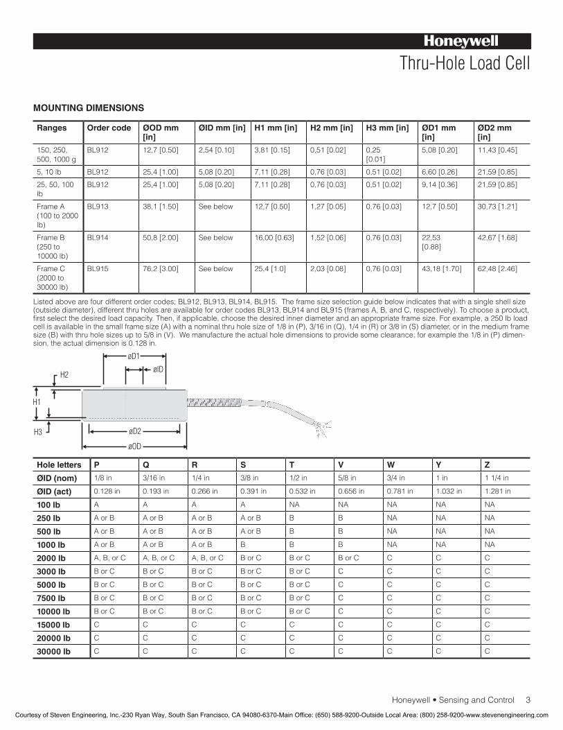
Honeywell•SensingandControl3
Thru-Hole Load Cell
MOUNTING DIMENSIONS
Ranges Order code ØOD mm [in]
ØID mm [in] H1 mm [in] H2 mm [in] H3 mm [in] ØD1 mm [in]
ØD2 mm [in]
150, 250, 500, 1000 g
BL912 12,7 [0.50] 2,54 [0.10] 3,81 [0.15] 0,51 [0.02] 0,25[0.01]
5,08 [0.20] 11,43 [0.45]
5, 10 lb BL912 25,4 [1.00] 5,08 [0.20] 7,11 [0.28] 0,76 [0.03] 0,51 [0.02] 6,60 [0.26] 21,59 [0.85]
25, 50, 100 lb
BL912 25,4 [1.00] 5,08 [0.20] 7,11 [0.28] 0,76 [0.03] 0,51 [0.02] 9,14 [0.36] 21,59 [0.85]
Frame A (100 to 2000 lb)
BL913 38,1 [1.50] See below 12,7 [0.50] 1,27 [0.05] 0,76 [0.03] 12,7 [0.50] 30,73 [1.21]
Frame B (250 to 10000 lb)
BL914 50,8 [2.00] See below 16,00 [0.63] 1,52 [0.06] 0,76 [0.03] 22,53[0.88]
42,67 [1.68]
Frame C (2000 to 30000 lb)
BL915 76,2 [3.00] See below 25,4 [1.0] 2,03 [0.08] 0,76 [0.03] 43,18 [1.70] 62,48 [2.46]
Listed above are four different order codes; BL912, BL913, BL914, BL915. The frame size selection guide below indicates that with a single shell size (outside diameter), different thru holes are available for order codes BL913, BL914 and BL915 (frames A, B, and C, respectively). To choose a product, firstselectthedesiredloadcapacity.Then,ifapplicable,choosethedesiredinnerdiameterandanappropriateframesize.Forexample,a250lbloadcell is available in the small frame size (A) with a nominal thru hole size of 1/8 in (P), 3/16 in (Q), 1/4 in (R) or 3/8 in (S) diameter, or in the medium frame size (B) with thru hole sizes up to 5/8 in (V). We manufacture the actual hole dimensions to provide some clearance; for example the 1/8 in (P) dimen-sion, the actual dimension is 0.128 in.
Hole letters P Q R S T V W Y Z
ØID (nom) 1/8 in 3/16 in 1/4 in 3/8 in 1/2 in 5/8 in 3/4 in 1 in 1 1/4 in
ØID (act) 0.128 in 0.193 in 0.266 in 0.391 in 0.532 in 0.656 in 0.781 in 1.032 in 1.281 in
100 lb A A A A NA NA NA NA NA
250 lb A or B A or B A or B A or B B B NA NA NA
500 lb A or B A or B A or B A or B B B NA NA NA
1000 lb A or B A or B A or B B B B NA NA NA
2000 lb A, B, or C A, B, or C A, B, or C B or C B or C B or C C C C
3000 lb B or C B or C B or C B or C B or C C C C C
5000 lb B or C B or C B or C B or C B or C C C C C
7500 lb B or C B or C B or C B or C B or C C C C C
10000 lb B or C B or C B or C B or C B or C C C C C
15000 lb C C C C C C C C C
20000 lb C C C C C C C C C
30000 lb C C C C C C C C C
Courtesy of Steven Engineering, Inc.-230 Ryan Way, South San Francisco, CA 94080-6370-Main Office: (650) 588-9200-Outside Local Area: (800) 258-9200-www.stevenengineering.com
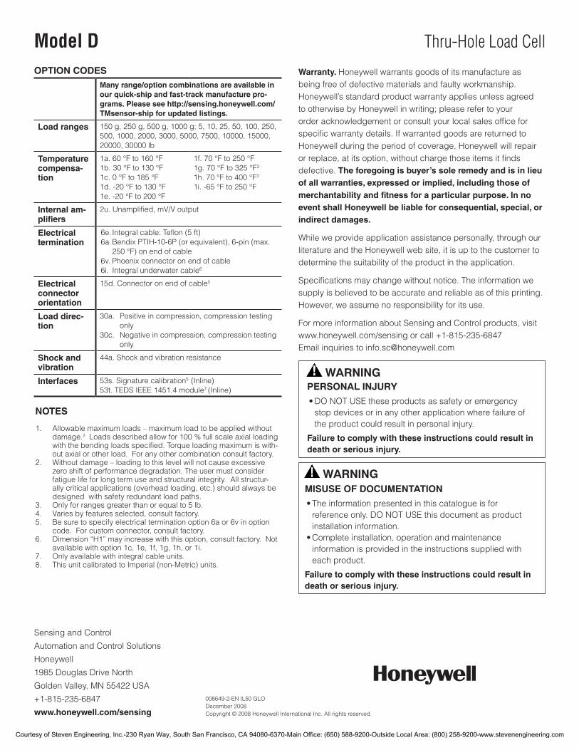
Sensing and Control
Automation and Control Solutions
Honeywell
1985 Douglas Drive North
Golden Valley, MN 55422 USA
+1-815-235-6847
www.honeywell.com/sensing
008649-2-EN IL50 GLO December 2008Copyright © 2008 Honeywell International Inc. All rights reserved.
Model D Thru-Hole Load Cell
OPTION CODESMany range/option combinations are available in our quick-ship and fast-track manufacture pro-grams. Please see http://sensing.honeywell.com/TMsensor-ship for updated listings.
Load ranges 150 g, 250 g, 500 g, 1000 g; 5, 10, 25, 50, 100, 250, 500, 1000, 2000, 3000, 5000, 7500, 10000, 15000, 20000, 30000 lb
Temperature compensa-tion
1a. 60 °F to 160 °F1b. 30 °F to 130 °F1c. 0 °F to 185 °F1d. -20 °F to 130 °F1e. -20 °F to 200 °F
1f. 70 °F to 250 °F 1g. 70 °F to 325 °F3
1h. 70 °F to 400 °F3
1i. -65 °F to 250 °F
Internal am-plifiers
2u.Unamplified,mV/Voutput
Electrical termination
6e. Integral cable: Teflon (5 ft)6a. Bendix PTIH-10-6P (or equivalent), 6-pin (max.
250 °F) on end of cable6v. Phoenix connector on end of cable6i. Integral underwater cable6
Electrical connector orientation
15d. Connector on end of cable5
Load direc-tion
30a. Positive in compression, compression testing only
30c. Negative in compression, compression testing only
Shock and vibration
44a. Shock and vibration resistance
Interfaces 53s. Signature calibration5 (Inline)53t. TEDS IEEE 1451.4 module7 (Inline)
NOTES
1. Allowable maximum loads – maximum load to be applied without damage.2 Loads described allow for 100 % full scale axial loading
withthebendingloadsspecified.Torqueloadingmaximumiswith-out axial or other load. For any other combination consult factory.
2. Without damage – loading to this level will not cause excessive zero shift of performance degradation. The user must consider fatigue life for long term use and structural integrity. All structur-ally critical applications (overhead loading, etc.) should always be designed with safety redundant load paths.
3. Only for ranges greater than or equal to 5 lb.4. Varies by features selected, consult factory.5. Be sure to specify electrical termination option 6a or 6v in option
code. For custom connector, consult factory.6. Dimension “H1” may increase with this option, consult factory. Not
available with option 1c, 1e, 1f, 1g, 1h, or 1i.7. Only available with integral cable units.8. This unit calibrated to Imperial (non-Metric) units.
Warranty. Honeywell warrants goods of its manufacture as being free of defective materials and faulty workmanship. Honeywell’s standard product warranty applies unless agreed to otherwise by Honeywell in writing; please refer to your orderacknowledgementorconsultyourlocalsalesofficeforspecificwarrantydetails.IfwarrantedgoodsarereturnedtoHoneywell during the period of coverage, Honeywell will repair orreplace,atitsoption,withoutchargethoseitemsitfindsdefective. The foregoing is buyer’s sole remedy and is in lieu of all warranties, expressed or implied, including those of merchantability and fitness for a particular purpose. In no event shall Honeywell be liable for consequential, special, or indirect damages.
While we provide application assistance personally, through our literature and the Honeywell web site, it is up to the customer to determine the suitability of the product in the application.
Specificationsmaychangewithoutnotice.Theinformationwesupply is believed to be accurate and reliable as of this printing. However, we assume no responsibility for its use.
For more information about Sensing and Control products, visit www.honeywell.com/sensing or call +1-815-235-6847Email inquiries to [email protected]
WARNINGPERSONAL INJURY•DONOTUSEtheseproductsassafetyoremergencystopdevicesorinanyotherapplicationwherefailureoftheproductcouldresultinpersonalinjury.
Failure to comply with these instructions could result in death or serious injury.
WARNINGMISUSE OF DOCUMENTATION•Theinformationpresentedinthiscatalogueisforreferenceonly.DONOTUSEthisdocumentasproductinstallationinformation.•Completeinstallation,operationandmaintenanceinformationisprovidedintheinstructionssuppliedwitheachproduct.
Failure to comply with these instructions could result in death or serious injury.
Courtesy of Steven Engineering, Inc.-230 Ryan Way, South San Francisco, CA 94080-6370-Main Office: (650) 588-9200-Outside Local Area: (800) 258-9200-www.stevenengineering.com
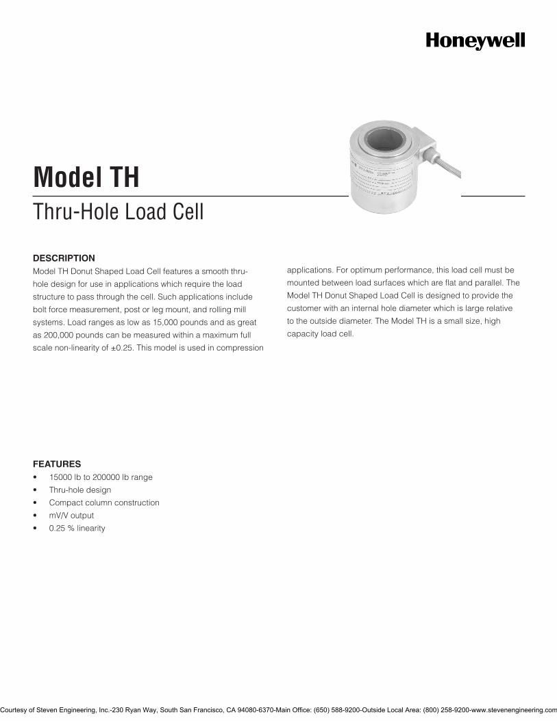
Thru-Hole Load CellModel TH
DESCRIPTIONModel TH Donut Shaped Load Cell features a smooth thru-
hole design for use in applications which require the load
structure to pass through the cell. Such applications include
bolt force measurement, post or leg mount, and rolling mill
systems. Load ranges as low as 15,000 pounds and as great
as 200,000 pounds can be measured within a maximum full
scale non-linearity of ±0.25. This model is used in compression
applications. For optimum performance, this load cell must be
mounted between load surfaces which are flat and parallel. The
Model TH Donut Shaped Load Cell is designed to provide the
customer with an internal hole diameter which is large relative
to the outside diameter. The Model TH is a small size, high
capacity load cell.
FEATURES• 15000lbto200000lbrange
• Thru-holedesign
• Compactcolumnconstruction
• mV/Voutput
• 0.25%linearity
Courtesy of Steven Engineering, Inc.-230 Ryan Way, South San Francisco, CA 94080-6370-Main Office: (650) 588-9200-Outside Local Area: (800) 258-9200-www.stevenengineering.com
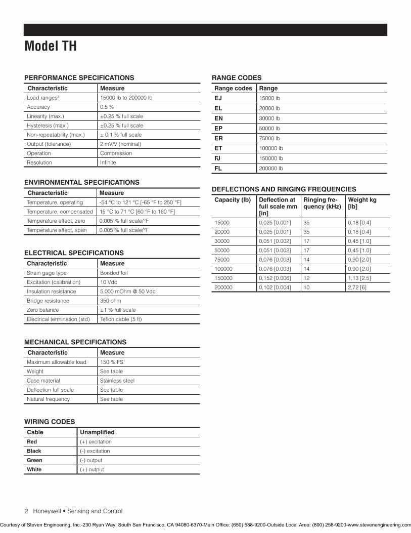
2Honeywell•SensingandControl
Model TH
PERFORMANCE SPECIFICATIONS
Characteristic Measure
Load ranges3 15000 lb to 200000 lb
Accuracy 0.5%
Linearity (max.) ±0.25%fullscale
Hysteresis (max.) ±0.25%fullscale
Non-repeatability (max.) ±0.1%fullscale
Output (tolerance) 2mV/V(nominal)
Operation Compression
Resolution Infinite
RANGE CODES
Range codes Range
EJ 15000 lb
EL 20000 lb
EN 30000 lb
EP 50000 lb
ER 75000 lb
ET 100000 lb
FJ 150000 lb
FL 200000 lb
ELECTRICAL SPECIFICATIONS
Characteristic Measure
Strain gage type Bonded foil
Excitation (calibration) 10Vdc
Insulation resistance 5,000mOhm@50Vdc
Bridge resistance 350 ohm
Zero balance ±1%fullscale
Electrical termination (std) Teflon cable (5 ft)
MECHANICAL SPECIFICATIONS
Characteristic Measure
Maximum allowable load 150%FS1
Weight See table
Case material Stainless steel
Deflection full scale See table
Natural frequency See table
WIRING CODES
Cable Unamplified
Red (+) excitation
Black (-) excitation
Green (-) output
White (+) output
ENVIRONMENTAL SPECIFICATIONS
Characteristic Measure
Temperature, operating -54 °C to 121 °C [-65 °F to 250 °F]
Temperature, compensated 15 °C to 71 °C [60 °F to 160 °F]
Temperature effect, zero 0.005%fullscale/°F
Temperature effect, span 0.005%fullscale/°F
DEFLECTIONS AND RINGING FREQUENCIES
Capacity (lb) Deflection at full scale mm [in]
Ringing fre-quency (kHz)
Weight kg [lb]
15000 0,025 [0.001] 35 0,18 [0.4]
20000 0,025 [0.001] 35 0,18 [0.4]
30000 0,051 [0.002] 17 0,45 [1.0]
50000 0,051 [0.002] 17 0,45 [1.0]
75000 0,076 [0.003] 14 0,90 [2.0]
100000 0,076 [0.003] 14 0,90 [2.0]
150000 0,152 [0.006] 12 1,13 [2.5]
200000 0,102 [0.004] 10 2,72 [6]
Courtesy of Steven Engineering, Inc.-230 Ryan Way, South San Francisco, CA 94080-6370-Main Office: (650) 588-9200-Outside Local Area: (800) 258-9200-www.stevenengineering.com
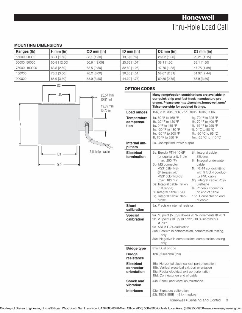
Honeywell•SensingandControl3
Thru-Hole Load Cell
MOUNTING DIMENSIONS
Ranges (lb) H mm [in] OD mm [in] ID mm [in] D2 mm [in] D3 mm [in]
15000, 20000 38,1 [1.50] 38,1 [1.50] 19,3 [0.76] 26,92 [1.06] 29,21 [1.15]
30000, 50000 50,8 [ [2.00] 50,8 [ [2.00] 25,65 [1.01] 38,1 [1.50] 38,1 [1.50]
75000, 100000 63,5 [2.50] 63,5 [2.50] 32,60 [1.26] 47,75 [1.88] 47,75 [1.88]
150000 76,2 [3.00] 76,2 [3.00] 38,35 [1.51] 58,67 [2.31] 61,97 [2.44]
200000 88,9 [3.50] 88,9 [3.50] 44,70 [1.76] 69,85 [2.75] 88,9 [3.50]
OPTION CODESMany range/option combinations are available in our quick-ship and fast-track manufacture pro-grams. Please see http://sensing.honeywell.com/TMsensor-ship for updated listings.
Load ranges 15K, 20K, 30K, 50K, 75K, 100K, 150K, 200K
Temperature compensa-tion
1a. 60 °F to 160 °F1b. 30 °F to 130 °F1c. 0 °F to 185 °F1d. -20 °F to 130 °F1e. -20 °F to 200 °F 1f. 70 °F to 250 °F
1g. 70 °F to 325 °F1h. 70 °F to 400 °F1i. -65 °F to 250 °F1j. 0 °C to 50 °C1k. -20 °C to 85 °C1m. -25 °C to 110 °C
Internal am-plifiers
2u.Unamplified,mV/Voutput
Electrical termination
6a. Bendix PTIH-10-6P (or equivalent), 6-pin (max. 250 °F)
6b. MS connector MS3102E-14S-6P (mates with MS3106E-14S-6S) (max. 160 °F)4
6e. Integral cable: Teflon (5 ft range)
6f.Integralcable:PVC6g. Integral cable: Neo-
prene
6h. Integral cable: Silicone
6i. Integral underwater cable
6j.1/2-14conduitfittingwith 5 ft of 4 conduc-torPVCcable
6q. Integral cable: Poly-urethane
6v. Phoenix connector on end of cable
15d. Connector on end of cable
Shunt calibration
8a. Precision internal resistor
Special calibration
9a.10point(5up/5down)20%increments@70°F9b.20point(10up/10down)10%increments @ 70 °F9c. ASTM E-74 calibration30a. Positive in compression, compression testing
only30c. Negative in compression, compression testing
only
Bridge type 31a. Dual bridge
Bridge resistance
12b. 5000 ohm (foil)
Electrical connector orientation
15a. Horizontal electrical exit port orientation15b.Verticalelectricalexitportorientation15c. Radial electrical exit port orientation15d. Connector on end of cable
Shock and vibration
44a. Shock and vibration resistance
Interfaces 53e. Signature calibration53t. TEDS IEEE 1451.4 module
Courtesy of Steven Engineering, Inc.-230 Ryan Way, South San Francisco, CA 94080-6370-Main Office: (650) 588-9200-Outside Local Area: (800) 258-9200-www.stevenengineering.com
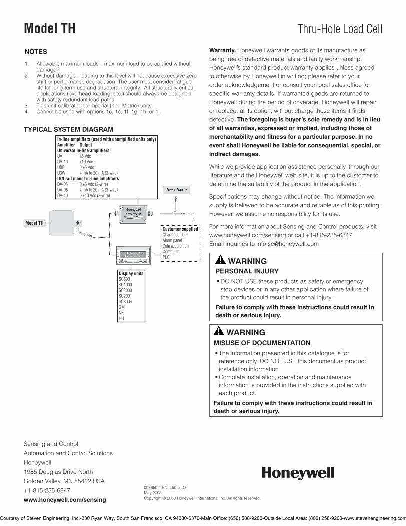
Sensing and Control
Automation and Control Solutions
Honeywell
1985 Douglas Drive North
GoldenValley,MN55422USA
+1-815-235-6847
www.honeywell.com/sensing
008650-1-EN IL50 GLO May 2008Copyright © 2008 Honeywell International Inc. All rights reserved.
Model TH Thru-Hole Load Cell
TYPICAL SYSTEM DIAGRAM
NOTES
1. Allowable maximum loads – maximum load to be applied without damage.2
2. Without damage - loading to this level will not cause excessive zero shift or performance degradation. The user must consider fatigue life for long-term use and structural integrity. All structurally critical applications (overhead loading, etc.) should always be designed with safety redundant load paths.
3. This unit calibrated to Imperial (non-Metric) units.4. Cannot be used with options 1c, 1e, 1f, 1g, 1h, or 1i.
Warranty. Honeywell warrants goods of its manufacture as being free of defective materials and faulty workmanship. Honeywell’s standard product warranty applies unless agreed to otherwise by Honeywell in writing; please refer to your order acknowledgement or consult your local sales office for specific warranty details. If warranted goods are returned to Honeywell during the period of coverage, Honeywell will repair or replace, at its option, without charge those items it finds defective. The foregoing is buyer’s sole remedy and is in lieu of all warranties, expressed or implied, including those of merchantability and fitness for a particular purpose. In no event shall Honeywell be liable for consequential, special, or indirect damages.
While we provide application assistance personally, through our literature and the Honeywell web site, it is up to the customer to determine the suitability of the product in the application.
Specifications may change without notice. The information we supply is believed to be accurate and reliable as of this printing. However, we assume no responsibility for its use.
For more information about Sensing and Control products, visit www.honeywell.com/sensingorcall+1-815-235-6847Email inquiries to [email protected]
WARNINGPERSONAL INJURY•DONOTUSEtheseproductsassafetyoremergencystopdevicesorinanyotherapplicationwherefailureoftheproductcouldresultinpersonalinjury.
Failure to comply with these instructions could result in death or serious injury.
WARNINGMISUSE OF DOCUMENTATION•Theinformationpresentedinthiscatalogueisforreferenceonly.DONOTUSEthisdocumentasproductinstallationinformation.•Completeinstallation,operationandmaintenanceinformationisprovidedintheinstructionssuppliedwitheachproduct.
Failure to comply with these instructions could result in death or serious injury.
Courtesy of Steven Engineering, Inc.-230 Ryan Way, South San Francisco, CA 94080-6370-Main Office: (650) 588-9200-Outside Local Area: (800) 258-9200-www.stevenengineering.com

Bolt and Engine Mount Force SensorModel 3719
DESCRIPTIONThe bolt force sensor is a unique transducer which is essentially
a hollow-compression strain gage load cell. It is designed to be
used with most strain gage indicators. The bolt force sensor is
a three-piece assembly consisting of: 1. a large hardened and
ground flat washer with one side beveled, 2. the sensor, and 3. a
small hardened and ground washer.
The three pieces are assembled for various applications. The
large washer isolates the sensor from the force application tool.
The beveled hole in this washer, which always faces away from
the sensor, provides clearance for the bolt head radius. When
a torque wrench is used, a torque vs. clamp force curve can be
generated. The 3719 bolt force sensor is designed for use in
fastener testing where the compression loading of the sensor
is induced by the tensile loading of the fastener. The bolt force
sensor must be used with the size fastener for which it was
designed.
FEATURES• Compact
• Highoutput
• Standardmodelsforboltssizeno.6thru2inand
up to 20 mm
• Sensorandwashers-carpenter440Cstainlesssteel
• Sensitivetoneitherboltnornut-appliedtorque
Courtesy of Steven Engineering, Inc.-230 Ryan Way, South San Francisco, CA 94080-6370-Main Office: (650) 588-9200-Outside Local Area: (800) 258-9200-www.stevenengineering.com
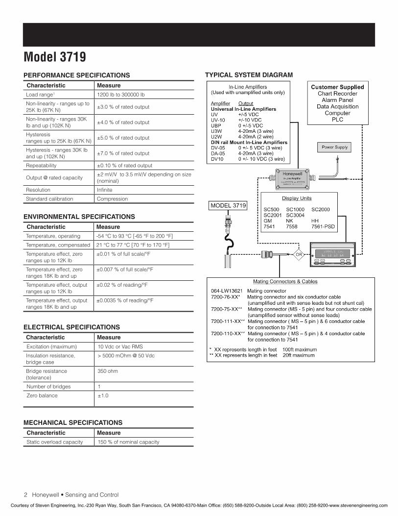
2Honeywell•SensingandControl
Model 3719PERFORMANCE SPECIFICATIONS
Characteristic Measure
Load range1 1200 lb to 300000 lb
Non-linearity - ranges up to 25Klb(67KN)
±3.0 % of rated output
Non-linearity - ranges 30K lbandup(102KN)
±4.0%ofratedoutput
Hysteresisrangesupto25Klb(67KN)
±5.0 % of rated output
Hysteresis-ranges30Klbandup(102KN)
±7.0 % of rated output
Repeatability ±0.10 % of rated output
Output @ rated capacity ±2 mV/V to 3.5 mV/V depending on size (nominal)
Resolution Infinite
Standardcalibration Compression
ENVIRONMENTAL SPECIFICATIONS
Characteristic Measure
Temperature, operating -54°Cto93°C[-65°Fto200°F]
Temperature, compensated 21°Cto77°C[70°Fto170°F]
Temperature effect, zero ranges up to 12K lb
±0.01%offullscale/°F
Temperature effect, zero ranges 18K lb and up
±0.007%offullscale/°F
Temperature effect, output ranges up to 12K lb
±0.02%ofreading/°F
Temperature effect, outputranges 18K lb and up
±0.0035%ofreading/°F
ELECTRICAL SPECIFICATIONS
Characteristic Measure
Excitation(maximum) 10VdcorVacRMS
Insulation resistance, bridge case
> 5000 mOhm @ 50 Vdc
Bridge resistance (tolerance)
350 ohm
Number of bridges 1
Zero balance ±1.0
MECHANICAL SPECIFICATIONS
Characteristic Measure
Staticoverloadcapacity 150 % of nominal capacity
TYPICAL SYSTEM DIAGRAM
Courtesy of Steven Engineering, Inc.-230 Ryan Way, South San Francisco, CA 94080-6370-Main Office: (650) 588-9200-Outside Local Area: (800) 258-9200-www.stevenengineering.com

Honeywell•SensingandControl3
Bolt and Engine Mount Force SensorMOUNTING DIMENSIONSModel Bolt size Capacity lb C in ØD in ØA in ØB in T in
3719-138 No.6 1200 0.330 0.140 0.42 0.250 0.040
3719-164 No. 8 1800 0.330 0.166 0.47 0.300 0.040
3719-190 No. 10 2400 0.330 0.192 0.52 0.350 0.040
3719-250 1/4 5000 0.370 0.262 0.65 0.470 0.060
3719-312 5/16 7000 0.495 0.326 0.78 0.550 0.060
3719-375 3/8 10000 0.495 0.396 0.80 0.639 0.060
3719-437 7/16 12000 0.495 0.454 0.95 0.720 0.060
3719-500 1/2 20000 0.660 0.517 1.14 0.910 0.080
3719-562 9/16 25000 0.660 0.580 1.23 0.990 0.080
3719-625 5/8 30000 0.660 0.644 1.35 1.150 0.080
3719-750 3/4 45000 0.815 0.770 1.62 1.350 0.095
3719-875 7/8 60000 0.815 0.897 1.72 1.600 0.095
3719-1000 1 90000 0.815 1.024 2.00 1.800 0.095
3719-1125 1 1/8 80000 1.065 1.151 2.20 1.900 0.095
3719-1250 11/4 125000 1.125 1.279 2.40 2.250 0.125
3719-1500 1 1/2 190000 1.125 1.533 2.80 2.600 0.125
3719-1750 13/4 260000 1.300 1.787 3.20 3.000 0.150
3719-2000 2 300000 1.650 2.041 3.60 3.500 0.200
3719-6MM 6mm 17000* 9,40* 6,0* 16,3* 10,7* 1,5*
3719-7MM 7 mm 27000* 12,57* 7,1* 16,8* 12,2* 1,5*
3719-8MM 8 mm 31000* 12,57* 8,3* 19,8* 14,5* 1,5*
3719-9MM 9 mm 36000* 12,57* 9,0* 20,3* 15,2* 1,5*
3719-10MM 10 mm 46000* 12,57* 10,1* 20,3* 16,2* 1,5*
3719-12MM 12 mm 67000* 15,75* 12,0* 27,9 22,1* 1,5*
3719-14MM 14mm 102000* 16,76* 14,0* 31,8* 25,9* 2,0*
3719-15MM 15 mm 125000* 16,76* 15,5* 32,5* 26,4* 2,0*
3719-16MM 16mm 135000 16,76* 16,1* 34,3* 29,2* 2,0*
3719-18MM 18 mm 156000 19,94* 18,1* 36,8* 31,8* 2,0*
3719-20MM 20 mm 220000 20,70* 20,1* 43,2* 36,8* 2,4*
*CapacitiesinNewtons,*Dimensionsinmillimeters
Courtesy of Steven Engineering, Inc.-230 Ryan Way, South San Francisco, CA 94080-6370-Main Office: (650) 588-9200-Outside Local Area: (800) 258-9200-www.stevenengineering.com
008653-2-EN IL50 GLO March 2009Copyright © 2009 Honeywell International Inc. All rights reserved.
Model 3719 Bolt and Engine Mount Force Sensor
Sensing and Control
Honeywell
1985 Douglas Drive North
Golden Valley, MN 55422
www.honeywell.com
NOTES
1. ThisunitcalibratedtoImperial(non-Metric)units.
Warranty. Honeywellwarrantsgoodsofitsmanufactureasbeing free of defective materials and faulty workmanship. Honeywell’sstandardproductwarrantyappliesunlessagreedtootherwisebyHoneywellinwriting;pleaserefertoyourorder acknowledgement or consult your local sales office for specific warranty details. If warranted goods are returned to Honeywellduringtheperiodofcoverage,Honeywellwillrepairor replace, at its option, without charge those items it finds defective. The foregoing is buyer’s sole remedy and is in lieu of all warranties, expressed or implied, including those of merchantability and fitness for a particular purpose. In no event shall Honeywell be liable for consequential, special, or indirect damages.
While we provide application assistance personally, through our literatureandtheHoneywellwebsite,itisuptothecustomertodetermine the suitability of the product in the application.
Specificationsmaychangewithoutnotice.Theinformationwesupply is believed to be accurate and reliable as of this printing. However,weassumenoresponsibilityforitsuse.
WARNINGPERSONAL INJURY
•DONOTUSEtheseproductsassafetyoremergencystopdevicesorinanyotherapplicationwherefailureoftheproductcouldresultinpersonalinjury.
Failure to comply with these instructions could result in death or serious injury.
WARNINGMISUSE OF DOCUMENTATION
•Theinformationpresentedinthiscatalogueisforreferenceonly.DONOTUSEthisdocumentasproductinstallationinformation.•Completeinstallation,operationandmaintenanceinformationisprovidedintheinstructionssuppliedwitheachproduct.
Failure to comply with these instructions could result in death or serious injury.
Find out more
Honeywellservesitscustomers
through a worldwide network of
sales offices, representatives
anddistributors.Forapplication
assistance, current specifica-
tions, pricing or name of the
nearestAuthorizedDistributor,
contact your local sales office.
TolearnmoreaboutHoneywell’s
test and measurement products,
call +1-614-850-5000, visit
www.honeywell.com/sensotec,
or e-mail inquiries to
Courtesy of Steven Engineering, Inc.-230 Ryan Way, South San Francisco, CA 94080-6370-Main Office: (650) 588-9200-Outside Local Area: (800) 258-9200-www.stevenengineering.com
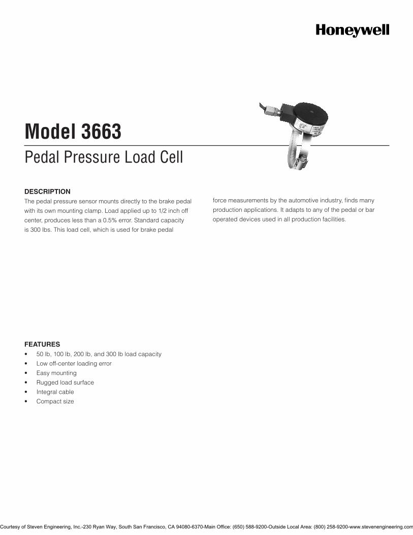
Pedal Pressure Load CellModel 3663
DESCRIPTIONThe pedal pressure sensor mounts directly to the brake pedal
with its own mounting clamp. Load applied up to 1/2 inch off
center, produces less than a 0.5% error. Standard capacity
is 300 lbs. This load cell, which is used for brake pedal
force measurements by the automotive industry, finds many
production applications. It adapts to any of the pedal or bar
operated devices used in all production facilities.
FEATURES• 50lb,100lb,200lb,and300lbloadcapacity
• Lowoff-centerloadingerror
• Easymounting
• Ruggedloadsurface
• Integralcable
• Compactsize
Courtesy of Steven Engineering, Inc.-230 Ryan Way, South San Francisco, CA 94080-6370-Main Office: (650) 588-9200-Outside Local Area: (800) 258-9200-www.stevenengineering.com
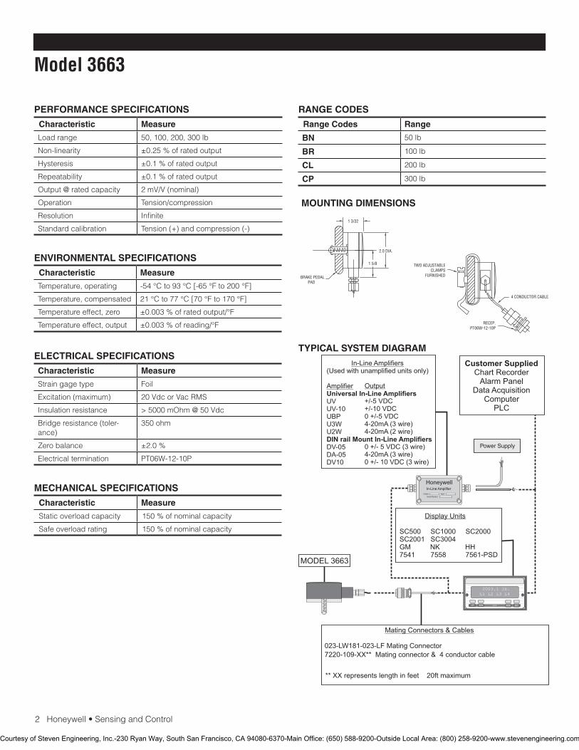
2Honeywell•SensingandControl
Model 3663
PERFORMANCE SPECIFICATIONS
Characteristic Measure
Load range 50, 100, 200, 300 lb
Non-linearity ±0.25 % of rated output
Hysteresis ±0.1 % of rated output
Repeatability ±0.1 % of rated output
Output @ rated capacity 2 mV/V (nominal)
Operation Tension/compression
Resolution Infinite
Standard calibration Tension(+)andcompression(-)
RANGE CODES
Range Codes Range
BN 50 lb
BR 100 lb
CL 200 lb
CP 300 lb
ELECTRICAL SPECIFICATIONS
Characteristic Measure
Strain gage type Foil
Excitation(maximum) 20VdcorVacRMS
Insulation resistance > 5000 mOhm @ 50 Vdc
Bridge resistance (toler-ance)
350 ohm
Zero balance ±2.0 %
Electricaltermination PT06W-12-10P
MECHANICAL SPECIFICATIONS
Characteristic Measure
Static overload capacity 150 % of nominal capacity
Safe overload rating 150 % of nominal capacity
ENVIRONMENTAL SPECIFICATIONS
Characteristic Measure
Temperature, operating -54°Cto93°C[-65°Fto200°F]
Temperature, compensated 21°Cto77°C[70°Fto170°F]
Temperatureeffect,zero ±0.003%ofratedoutput/°F
Temperature effect, output ±0.003%ofreading/°F
MOUNTING DIMENSIONS
TYPICAL SYSTEM DIAGRAM
HoneywellIn-Line Amplifier
Output InputSerial Number
Power Supply
Customer SuppliedChart Recorder
Alarm PanelData Acquisition
ComputerPLC
MODEL 3663
(Used with unamplified units only)
UVUV-10UBPU3WU2W
DV-05DA-05DV10
In-Line Amplifiers
Amplifier Universal In-Line Amplifiers
DIN rail Mount In-Line Amplifiers
Output
+/-5 VDC+/-10 VDC0 +/-5 VDC4-20mA (3 wire)4-20mA (2 wire)
0 +/- 5 VDC (3 wire)4-20mA (3 wire)0 +/- 10 VDC (3 wire)
2003.1 lb.L1 L2 L3 L4
UP DOWN
VALUE CLEAR CHAN TARE
ENTERSETUP EXIT
SC500 SC1000 SC2000 SC2001 SC3004 GM NK HH7541 7558 7561-PSD
Display Units
023-LW181-023-LF Mating Connector
** XX represents length in feet 20ft maximum
Mating Connectors & Cables
7220-109-XX** Mating connector & 4 conductor cable
BRAKE PEDALPAD
TWO ADJUSTABLECLAMPS
FURNISHED
2.0 DIA.
1 5/8
1 3/32
4 CONDUCTOR CABLE-8 FT.
RECEP.PT06W-12-10P
Courtesy of Steven Engineering, Inc.-230 Ryan Way, South San Francisco, CA 94080-6370-Main Office: (650) 588-9200-Outside Local Area: (800) 258-9200-www.stevenengineering.com

SensingandControl
AutomationandControlSolutions
Honeywell
1985DouglasDriveNorth
GoldenValley,MN55422USA
+1-815-235-6847
www.honeywell.com/sensing
008676-1-EN IL50 GLO May 2008Copyright © 2008 Honeywell International Inc. All rights reserved.
Model 3663 Pedal Pressure Load Cell
Warranty. Honeywell warrants goods of its manufacture as being free of defective materials and faulty workmanship. Honeywell’s standard product warranty applies unless agreed to otherwise by Honeywell in writing; please refer to your order acknowledgement or consult your local sales office for specific warranty details. If warranted goods are returned to Honeywell during the period of coverage, Honeywell will repair or replace, at its option, without charge those items it finds defective. The foregoing is buyer’s sole remedy and is in lieu of all warranties, expressed or implied, including those of merchantability and fitness for a particular purpose. In no event shall Honeywell be liable for consequential, special, or indirect damages.
While we provide application assistance personally, through our literature and the Honeywell web site, it is up to the customer to determine the suitability of the product in the application.
Specifications may change without notice. The information we supply is believed to be accurate and reliable as of this printing. However, we assume no responsibility for its use.
FormoreinformationaboutSensingandControlproducts,visitwww.honeywell.com/sensingorcall+1-815-235-6847Emailinquiriestoinfo.sc@honeywell.com
WARNINGPERSONAL INJURY•DONOTUSEtheseproductsassafetyoremergencystopdevicesorinanyotherapplicationwherefailureoftheproductcouldresultinpersonalinjury.
Failure to comply with these instructions could result in death or serious injury.
WARNINGMISUSE OF DOCUMENTATION•Theinformationpresentedinthiscatalogueisforreferenceonly.DONOTUSEthisdocumentasproductinstallationinformation.•Completeinstallation,operationandmaintenanceinformationisprovidedintheinstructionssuppliedwitheachproduct.
Failure to comply with these instructions could result in death or serious injury.
Courtesy of Steven Engineering, Inc.-230 Ryan Way, South San Francisco, CA 94080-6370-Main Office: (650) 588-9200-Outside Local Area: (800) 258-9200-www.stevenengineering.com
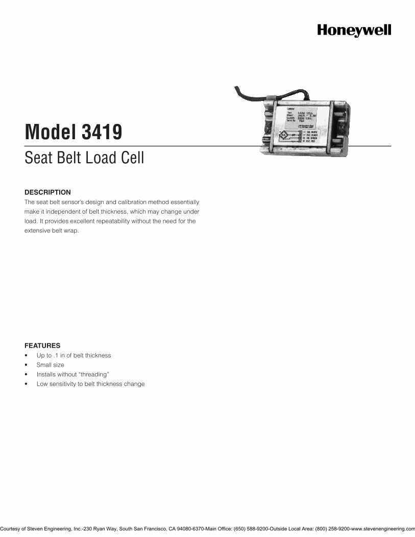
Seat Belt Load CellModel 3419
DESCRIPTIONThe seat belt sensor’s design and calibration method essentially
make it independent of belt thickness, which may change under
load. It provides excellent repeatability without the need for the
extensive belt wrap.
FEATURES• Upto.1inofbeltthickness
• Smallsize
• Installswithout“threading”
• Lowsensitivitytobeltthicknesschange
Courtesy of Steven Engineering, Inc.-230 Ryan Way, South San Francisco, CA 94080-6370-Main Office: (650) 588-9200-Outside Local Area: (800) 258-9200-www.stevenengineering.com
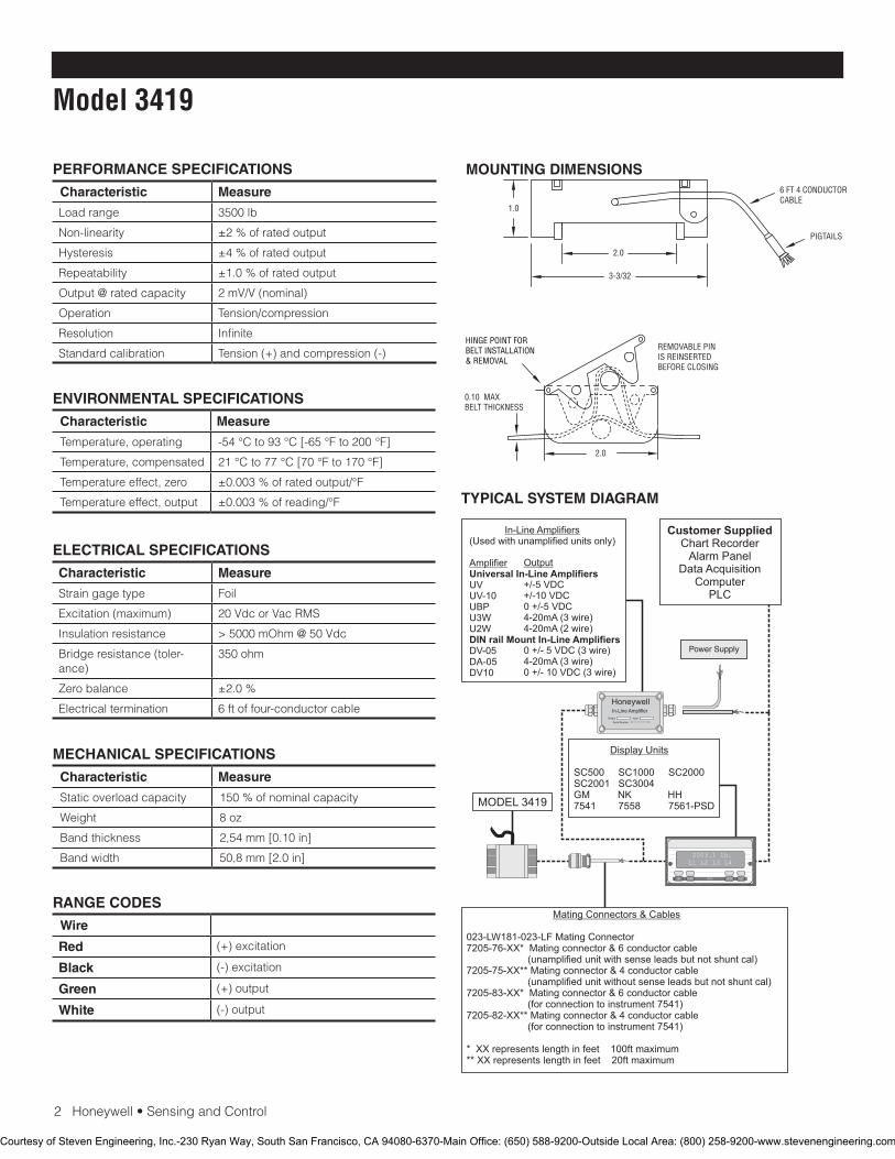
2Honeywell•SensingandControl
Model 3419
PERFORMANCE SPECIFICATIONS
Characteristic Measure
Loadrange 3500 lb
Non-linearity ±2 % of rated output
Hysteresis ±4 % of rated output
Repeatability ±1.0%ofratedoutput
Output @ rated capacity 2 mV/V (nominal)
Operation Tension/compression
Resolution Infinite
Standardcalibration Tension (+) and compression (-)
RANGE CODES
Wire
Red (+) excitation
Black (-) excitation
Green (+) output
White (-) output
ELECTRICAL SPECIFICATIONS
Characteristic Measure
Straingagetype Foil
Excitation (maximum) 20VdcorVacRMS
Insulation resistance > 5000 mOhm @ 50 Vdc
Bridge resistance (toler-ance)
350 ohm
Zero balance ±2.0 %
Electrical termination 6 ft of four-conductor cable
MECHANICAL SPECIFICATIONS
Characteristic Measure
Staticoverloadcapacity 150%ofnominalcapacity
Weight 8oz
Band thickness 2,54mm[0.10in]
Band width 50,8mm[2.0in]
ENVIRONMENTAL SPECIFICATIONS
Characteristic Measure
Temperature, operating -54°Cto93°C[-65°Fto200°F]
Temperature, compensated 21°Cto77°C[70°Fto170°F]
Temperatureeffect,zero ±0.003 % of rated output/°F
Temperature effect, output ±0.003 % of reading/°F
MOUNTING DIMENSIONS
TYPICAL SYSTEM DIAGRAM
HoneywellIn-Line Amplifier
Output InputSerial Number
Power Supply
Customer SuppliedChart Recorder
Alarm PanelData Acquisition
ComputerPLC
MODEL 3419
(Used with unamplified units only)
UVUV-10UBPU3WU2W
DV-05DA-05DV10
In-Line Amplifiers
Amplifier Universal In-Line Amplifiers
DIN rail Mount In-Line Amplifiers
Output
+/-5 VDC+/-10 VDC0 +/-5 VDC4-20mA (3 wire)4-20mA (2 wire)
0 +/- 5 VDC (3 wire)4-20mA (3 wire)0 +/- 10 VDC (3 wire)
2003.1 lb.L1 L2 L3 L4
UP DOWN
VALUE CLEAR CHAN TARE
ENTERSETUP EXIT
SC500 SC1000 SC2000 SC2001 SC3004 GM NK HH7541 7558 7561-PSD
Display Units
023-LW181-023-LF Mating Connector7205-76-XX* Mating connector & 6 conductor cable (unamplified unit with sense leads but not shunt cal)7205-75-XX** Mating connector & 4 conductor cable (unamplified unit without sense leads but not shunt cal)7205-83-XX* Mating connector & 6 conductor cable (for connection to instrument 7541)7205-82-XX** Mating connector & 4 conductor cable (for connection to instrument 7541)
* XX represents length in feet 100ft maximum** XX represents length in feet 20ft maximum
Mating Connectors & Cables
1.0
2.0
3-3/32
2.0
HINGE POINT FORBELT INSTALLATION& REMOVAL
REMOVABLE PINIS REINSERTEDBEFORE CLOSING
0.10 MAXBELT THICKNESS
6 FT 4 CONDUCTORCABLE
PIGTAILS
Courtesy of Steven Engineering, Inc.-230 Ryan Way, South San Francisco, CA 94080-6370-Main Office: (650) 588-9200-Outside Local Area: (800) 258-9200-www.stevenengineering.com
SensingandControl
AutomationandControlSolutions
Honeywell
1985DouglasDriveNorth
GoldenValley,MN55422USA
+1-815-235-6847
www.honeywell.com/sensing
008677-1-EN IL50 GLO May 2008Copyright © 2008 Honeywell International Inc. All rights reserved.
Models 3419 Seat Belt Load Cell
Warranty. Honeywell warrants goods of its manufacture as being free of defective materials and faulty workmanship. Honeywell’s standard product warranty applies unless agreed to otherwise by Honeywell in writing; please refer to your order acknowledgement or consult your local sales office for specific warranty details. If warranted goods are returned to Honeywell during the period of coverage, Honeywell will repair or replace, at its option, without charge those items it finds defective. The foregoing is buyer’s sole remedy and is in lieu of all warranties, expressed or implied, including those of merchantability and fitness for a particular purpose. In no event shall Honeywell be liable for consequential, special, or indirect damages.
While we provide application assistance personally, through our literature and the Honeywell web site, it is up to the customer to determine the suitability of the product in the application.
Specificationsmaychangewithoutnotice.Theinformationwesupply is believed to be accurate and reliable as of this printing. However, we assume no responsibility for its use.
FormoreinformationaboutSensingandControlproducts,visitwww.honeywell.com/sensingorcall+1-815-235-6847Email inquiries to [email protected]
WARNINGPERSONAL INJURY•DONOTUSEtheseproductsassafetyoremergencystopdevicesorinanyotherapplicationwherefailureoftheproductcouldresultinpersonalinjury.
Failure to comply with these instructions could result in death or serious injury.
WARNINGMISUSE OF DOCUMENTATION•Theinformationpresentedinthiscatalogueisforreferenceonly.DONOTUSEthisdocumentasproductinstallationinformation.•Completeinstallation,operationandmaintenanceinformationisprovidedintheinstructionssuppliedwitheachproduct.
Failure to comply with these instructions could result in death or serious injury.
Courtesy of Steven Engineering, Inc.-230 Ryan Way, South San Francisco, CA 94080-6370-Main Office: (650) 588-9200-Outside Local Area: (800) 258-9200-www.stevenengineering.com
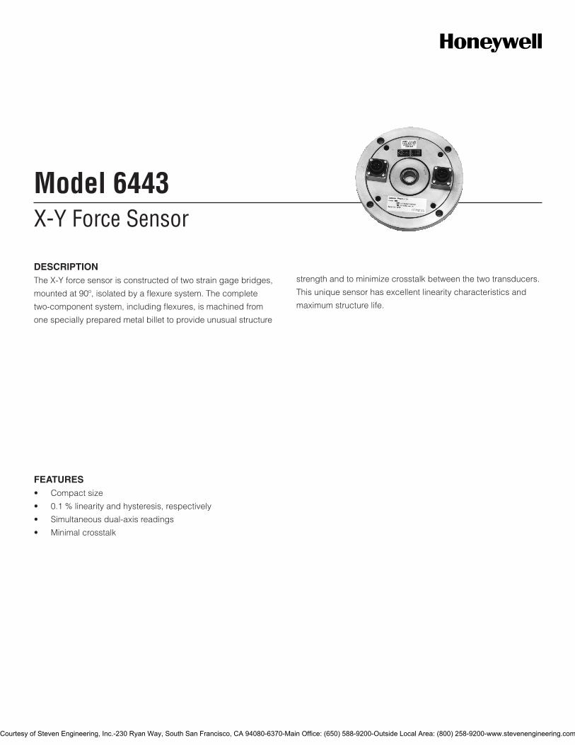
X-Y Force SensorModel 6443
DESCRIPTIONThe X-Y force sensor is constructed of two strain gage bridges,
mounted at 90º, isolated by a flexure system. The complete
two-component system, including flexures, is machined from
one specially prepared metal billet to provide unusual structure
strength and to minimize crosstalk between the two transducers.
This unique sensor has excellent linearity characteristics and
maximum structure life.
FEATURES• Compactsize
• 0.1%linearityandhysteresis,respectively
• Simultaneousdual-axisreadings
• Minimalcrosstalk
Courtesy of Steven Engineering, Inc.-230 Ryan Way, South San Francisco, CA 94080-6370-Main Office: (650) 588-9200-Outside Local Area: (800) 258-9200-www.stevenengineering.com
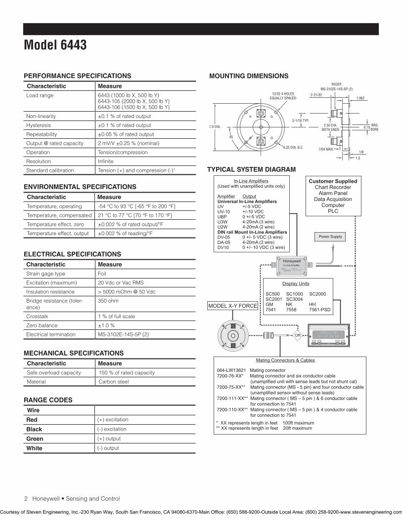
2Honeywell•SensingandControl
Model 6443
PERFORMANCE SPECIFICATIONS
Characteristic Measure
Load range 6443(1000lbX,500lbY)6443-105(2000lbX,500lbY)6443-106(1500lbX,500lbY)
Non-linearity ±0.1%ofratedoutput
Hysteresis ±0.1%ofratedoutput
Repeatability ±0.05%ofratedoutput
Output @ rated capacity 2mV/V±0.25%(nominal)
Operation Tension/compression
Resolution Infinite
Standardcalibration Tension(+)andcompression(-)1
RANGE CODES
Wire
Red (+)excitation
Black (-)excitation
Green (+)output
White (-)output
ELECTRICAL SPECIFICATIONS
Characteristic Measure
Straingagetype Foil
Excitation(maximum) 20VdcorVacRMS
Insulation resistance >5000mOhm@50Vdc
Bridge resistance (toler-ance)
350ohm
Crosstalk 1%offullscale
Zero balance ±1.0%
Electrical termination MS-3102E-14S-5P(2)
MECHANICAL SPECIFICATIONS
Characteristic Measure
Safeoverloadcapacity 150%ofratedcapacity
Material Carbonsteel
ENVIRONMENTAL SPECIFICATIONS
Characteristic Measure
Temperature, operating -54°Cto93°C[-65°Fto200°F]
Temperature, compensated 21°Cto77°C[70°Fto170°F]
Temperature effect, zero ±0.002%ofratedoutput/°F
Temperature effect, output ±0.002%ofreading/°F
MOUNTING DIMENSIONS
TYPICAL SYSTEM DIAGRAM
HoneywellIn-Line Amplifier
Output InputSerial Number
Power Supply
Customer SuppliedChart Recorder
Alarm PanelData Acquisition
ComputerPLC
MODEL X-Y FORCE
(Used with unamplified units only)
UVUV-10UBPU3WU2W
DV-05DA-05DV10
In-Line Amplifiers
Amplifier Universal In-Line Amplifiers
DIN rail Mount In-Line Amplifiers
Output
+/-5 VDC+/-10 VDC0 +/-5 VDC4-20mA (3 wire)4-20mA (2 wire)
0 +/- 5 VDC (3 wire)4-20mA (3 wire)0 +/- 10 VDC (3 wire)
2003.1 lb.L1 L2 L3 L4
UP DOWN
VALUE CLEAR CHAN TARE
ENTERSETUP EXIT
SC500 SC1000 SC2000 SC2001 SC3004 GM NK HH7541 7558 7561-PSD
Display Units
* XX represents length in feet 100ft maximum** XX represents length in feet 20ft maximum
Mating Connectors & Cables
OR
064-LW13621 Mating connector7200-76-XX* Mating connector and six conductor cable (unamplified unit with sense leads but not shunt cal)7200-75-XX** Mating connector (MS - 5 pin) and four conductor cable (unamplified sensor without sense leads)7200-111-XX** Mating connector ( MS – 5 pin ) & 6 conductor cable for connection to 7541 7200-110-XX** Mating connector ( MS – 5 pin ) & 4 conductor cable for connection to 7541
7.0 DIA.
13/32 4 HOLESEQUALLY SPACED
6.25 DIA. B.C.
45
2-21/321.062
2-1/16 TYP.2.50 DIA.
BOTH ENDS 0.75
1/87/64 MAX.
1.0
RECEP.MS-3102E-14S-5P (2)
BRGBORE
Courtesy of Steven Engineering, Inc.-230 Ryan Way, South San Francisco, CA 94080-6370-Main Office: (650) 588-9200-Outside Local Area: (800) 258-9200-www.stevenengineering.com
SensingandControl
AutomationandControlSolutions
Honeywell
1985DouglasDriveNorth
GoldenValley,MN55422USA
+1-815-235-6847
www.honeywell.com/sensing
008836-1-EN IL50 GLO June 2008Copyright © 2008 Honeywell International Inc. All rights reserved.
Models 6443 X-Y Force Sensor
Warranty. Honeywell warrants goods of its manufacture as being free of defective materials and faulty workmanship. Honeywell’s standard product warranty applies unless agreed to otherwise by Honeywell in writing; please refer to your order acknowledgement or consult your local sales office for specific warranty details. If warranted goods are returned to Honeywell during the period of coverage, Honeywell will repair or replace, at its option, without charge those items it finds defective. The foregoing is buyer’s sole remedy and is in lieu of all warranties, expressed or implied, including those of merchantability and fitness for a particular purpose. In no event shall Honeywell be liable for consequential, special, or indirect damages.
While we provide application assistance personally, through our literature and the Honeywell web site, it is up to the customer to determine the suitability of the product in the application.
Specificationsmaychangewithoutnotice.Theinformationwesupply is believed to be accurate and reliable as of this printing. However, we assume no responsibility for its use.
FormoreinformationaboutSensingandControlproducts,visitwww.honeywell.com/sensingorcall+1-815-235-6847Email inquiries to [email protected]
WARNINGPERSONAL INJURY
•DONOTUSEtheseproductsassafetyoremergencystopdevicesorinanyotherapplicationwherefailureofthe product could result in personal injury.
Failure to comply with these instructions could result in death or serious injury.
WARNINGMISUSE OF DOCUMENTATION
•Theinformationpresentedinthiscatalogueisforreferenceonly.DONOTUSEthisdocumentasproductinstallationinformation.•Completeinstallation,operationandmaintenanceinformationisprovidedintheinstructionssuppliedwitheach product.
Failure to comply with these instructions could result in death or serious injury.
NOTES1. Standardcalibrationfortension/compressionloadcellsisinten-
sion only.
Courtesy of Steven Engineering, Inc.-230 Ryan Way, South San Francisco, CA 94080-6370-Main Office: (650) 588-9200-Outside Local Area: (800) 258-9200-www.stevenengineering.com
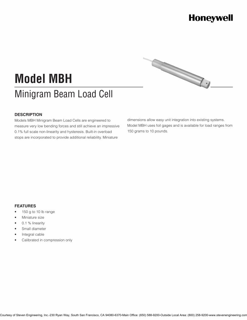
Minigram Beam Load CellModel MBH
DESCRIPTIONModels MBH Minigram Beam Load Cells are engineered to
measure very low bending forces and still achieve an impressive
0.1% full scale non-linearity and hysteresis. Built-in overload
stops are incorporated to provide additional reliability. Miniature
dimensions allow easy unit integration into existing systems.
Model MBH uses foil gages and is available for load ranges from
150 grams to 10 pounds.
FEATURES• 150gto10lbrange
• Miniaturesize
• 0.1%linearity
• Smalldiameter
• Integralcable
• Calibratedincompressiononly
Courtesy of Steven Engineering, Inc.-230 Ryan Way, South San Francisco, CA 94080-6370-Main Office: (650) 588-9200-Outside Local Area: (800) 258-9200-www.stevenengineering.com
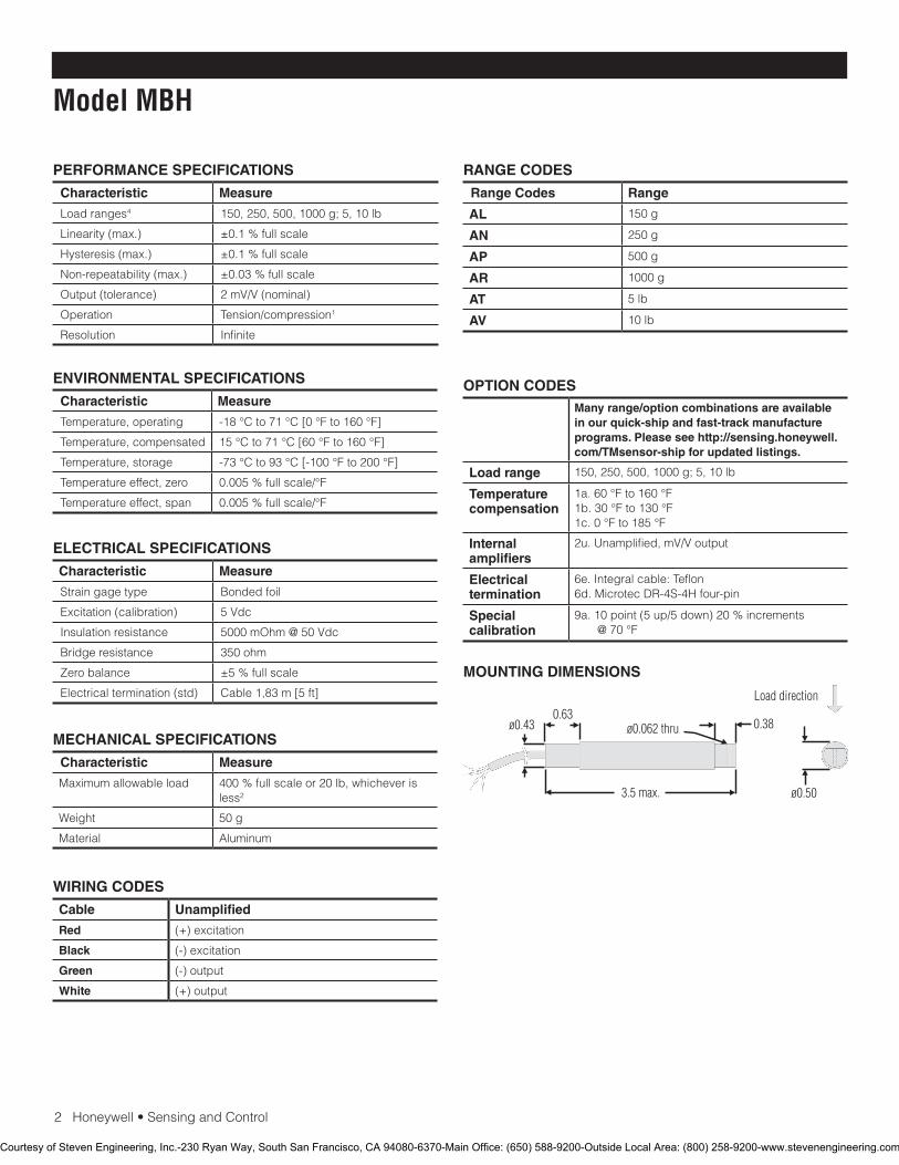
2Honeywell•SensingandControl
Model MBH
PERFORMANCE SPECIFICATIONS
Characteristic Measure
Load ranges4 150, 250, 500, 1000 g; 5, 10 lb
Linearity (max.) ±0.1 % full scale
Hysteresis (max.) ±0.1 % full scale
Non-repeatability (max.) ±0.03 % full scale
Output (tolerance) 2 mV/V (nominal)
Operation Tension/compression1
Resolution Infinite
RANGE CODES
Range Codes Range
AL 150 g
AN 250 g
AP 500 g
AR 1000 g
AT 5 lb
AV 10 lb
ELECTRICAL SPECIFICATIONS
Characteristic Measure
Straingagetype Bonded foil
Excitation (calibration) 5 Vdc
Insulationresistance 5000 mOhm @ 50 Vdc
Bridge resistance 350 ohm
Zero balance ±5 % full scale
Electrical termination (std) Cable 1,83 m [5 ft]
MECHANICAL SPECIFICATIONS
Characteristic Measure
Maximum allowable load 400 % full scale or 20 lb, whichever is less2
Weight 50 g
Material Aluminum
WIRING CODES
Cable Unamplified
Red (+) excitation
Black (-) excitation
Green (-) output
White (+) output
MOUNTING DIMENSIONS
ENVIRONMENTAL SPECIFICATIONS
Characteristic Measure
Temperature, operating -18 °C to 71 °C [0 °F to 160 °F]
Temperature, compensated 15 °C to 71 °C [60 °F to 160 °F]
Temperature, storage -73 °C to 93 °C [-100 °F to 200 °F]
Temperatureeffect,zero 0.005 % full scale/°F
Temperature effect, span 0.005 % full scale/°F
OPTION CODESMany range/option combinations are available in our quick-ship and fast-track manufacture programs. Please see http://sensing.honeywell.com/TMsensor-ship for updated listings.
Load range 150, 250, 500, 1000 g; 5, 10 lb
Temperaturecompensation
1a. 60 °F to 160 °F1b. 30 °F to 130 °F1c. 0 °F to 185 °F
Internal amplifiers
2u.Unamplified,mV/Voutput
Electrical termination
6e.Integralcable:Teflon6d.MicrotecDR-4S-4Hfour-pin
Special calibration
9a. 10 point (5 up/5 down) 20 % increments @ 70 °F
Courtesy of Steven Engineering, Inc.-230 Ryan Way, South San Francisco, CA 94080-6370-Main Office: (650) 588-9200-Outside Local Area: (800) 258-9200-www.stevenengineering.com
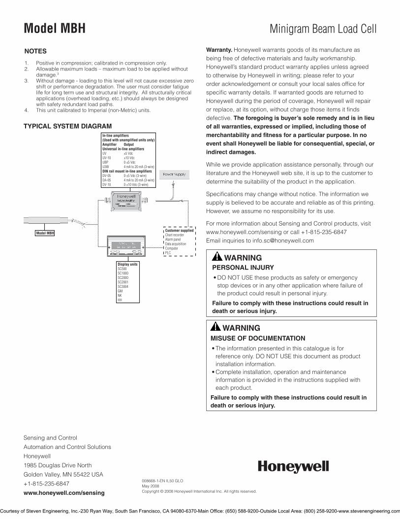
SensingandControl
AutomationandControlSolutions
Honeywell
1985 Douglas Drive North
GoldenValley,MN55422USA
+1-815-235-6847
www.honeywell.com/sensing
008668-1-EN IL50 GLO May 2008Copyright © 2008 Honeywell International Inc. All rights reserved.
Model MBH Minigram Beam Load Cell
TYPICAL SYSTEM DIAGRAM
NOTES
1. Positive in compression; calibrated in compression only.2. Allowable maximum loads – maximum load to be applied without
damage.3 3. Withoutdamage-loadingtothislevelwillnotcauseexcessivezero
shift or performance degradation. The user must consider fatigue life for long term use and structural integrity. All structurally critical applications (overhead loading, etc.) should always be designed with safety redundant load paths.
4. ThisunitcalibratedtoImperial(non-Metric)units.
Warranty. Honeywell warrants goods of its manufacture as being free of defective materials and faulty workmanship. Honeywell’s standard product warranty applies unless agreed to otherwise by Honeywell in writing; please refer to your orderacknowledgementorconsultyourlocalsalesofficeforspecificwarrantydetails.IfwarrantedgoodsarereturnedtoHoneywell during the period of coverage, Honeywell will repair orreplace,atitsoption,withoutchargethoseitemsitfindsdefective. The foregoing is buyer’s sole remedy and is in lieu of all warranties, expressed or implied, including those of merchantability and fitness for a particular purpose. In no event shall Honeywell be liable for consequential, special, or indirect damages.
While we provide application assistance personally, through our literature and the Honeywell web site, it is up to the customer to determine the suitability of the product in the application.
Specificationsmaychangewithoutnotice.Theinformationwesupply is believed to be accurate and reliable as of this printing. However, we assume no responsibility for its use.
FormoreinformationaboutSensingandControlproducts,visitwww.honeywell.com/sensing or call +1-815-235-6847Email inquiries to [email protected]
WARNINGPERSONAL INJURY
•DONOTUSEtheseproductsassafetyoremergencystopdevicesorinanyotherapplicationwherefailureoftheproductcouldresultinpersonalinjury.
Failure to comply with these instructions could result in death or serious injury.
WARNINGMISUSE OF DOCUMENTATION
•Theinformationpresentedinthiscatalogueisforreferenceonly.DONOTUSEthisdocumentasproductinstallationinformation.•Completeinstallation,operationandmaintenanceinformationisprovidedintheinstructionssuppliedwitheachproduct.
Failure to comply with these instructions could result in death or serious injury.
Courtesy of Steven Engineering, Inc.-230 Ryan Way, South San Francisco, CA 94080-6370-Main Office: (650) 588-9200-Outside Local Area: (800) 258-9200-www.stevenengineering.com
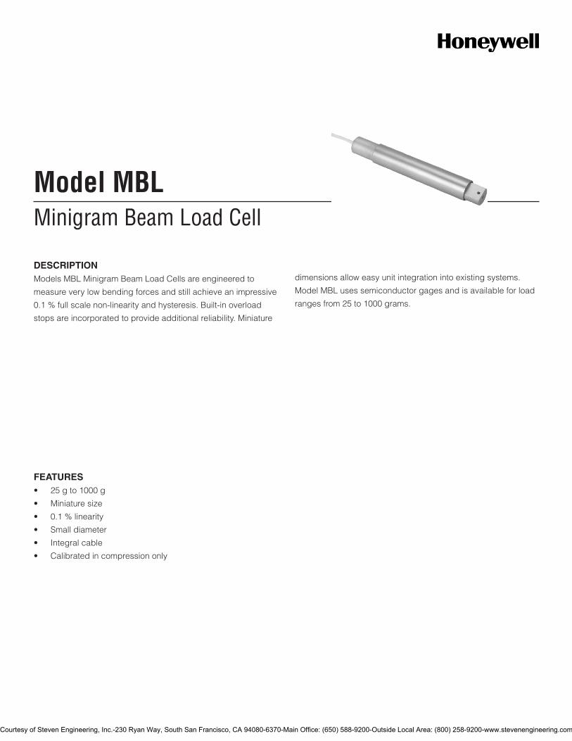
Minigram Beam Load CellModel MBL
DESCRIPTIONModels MBL Minigram Beam Load Cells are engineered to
measure very low bending forces and still achieve an impressive
0.1 % full scale non-linearity and hysteresis. Built-in overload
stops are incorporated to provide additional reliability. Miniature
dimensions allow easy unit integration into existing systems.
Model MBL uses semiconductor gages and is available for load
ranges from 25 to 1000 grams.
FEATURES• 25gto1000g
• Miniaturesize
• 0.1%linearity
• Smalldiameter
• Integralcable
• Calibratedincompressiononly
Courtesy of Steven Engineering, Inc.-230 Ryan Way, South San Francisco, CA 94080-6370-Main Office: (650) 588-9200-Outside Local Area: (800) 258-9200-www.stevenengineering.com
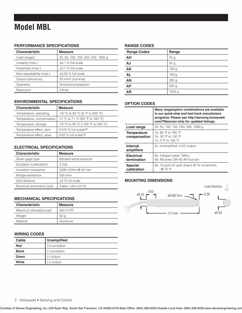
2Honeywell•SensingandControl
Model MBL
PERFORMANCE SPECIFICATIONS
Characteristic Measure
Load ranges4 25, 50, 100, 150, 250, 500, 1000 g
Linearity (max.) ±0.1 % full scale
Hysteresis (max.) ±0.1 % full scale
Non-repeatability (max.) ±0.03 % full scale
Output (tolerance) 20 mV/V (nominal)
Operation Tension/compression1
Resolution Infinite
RANGE CODES
Range Codes Range
AH 25 g
AJ 50 g
AK 100 g
AL 150 g
AN 250 g
AP 500 g
AR 1000 g
ELECTRICAL SPECIFICATIONS
Characteristic Measure
Straingagetype Bonded semiconductor
Excitation (calibration) 5 Vdc
Insulationresistance 5000 mOhm @ 50 Vdc
Bridge resistance 500 ohm
Zero balance ±5 % full scale
Electrical termination (std) Cable 1,83 m [5 ft]
MECHANICAL SPECIFICATIONS
Characteristic Measure
Maximum allowable load 400%FS2
Weight 50 g
Material Aluminum
WIRING CODES
Cable Unamplified
Red (+) excitation
Black (-) excitation
Green (-) output
White (+) output
MOUNTING DIMENSIONS
ENVIRONMENTAL SPECIFICATIONS
Characteristic Measure
Temperature, operating -18 °C to 93 °C [0 °F to 200 °F]
Temperature, compensated 15 °C to 71 °C [60 °F to 160 °F]
Temperature, storage -73 °C to 93 °C [-100 °F to 200 °F]
Temperatureeffect,zero 0.015 % full scale/°F
Temperature effect, span 0.02 % full scale/°F
OPTION CODESMany range/option combinations are available in our quick-ship and fast-track manufacture programs. Please see http://sensing.honeywell.com/TMsensor-ship for updated listings.
Load range 25, 50, 100, 150, 250, 500, 1000 g
Temperaturecompensation
1a. 60 °F to 160 °F1b. 30 °F to 130 °F1c. 0 °F to 185 °F
Internal amplifiers
2u.Unamplified,mV/Voutput
Electrical termination
6e.Integralcable:Teflon6d.MicrotecDR-4S-4Hfour-pin
Special calibration
9a. 10 point (5 up/5 down) 20 % increments @ 70 °F
Courtesy of Steven Engineering, Inc.-230 Ryan Way, South San Francisco, CA 94080-6370-Main Office: (650) 588-9200-Outside Local Area: (800) 258-9200-www.stevenengineering.com
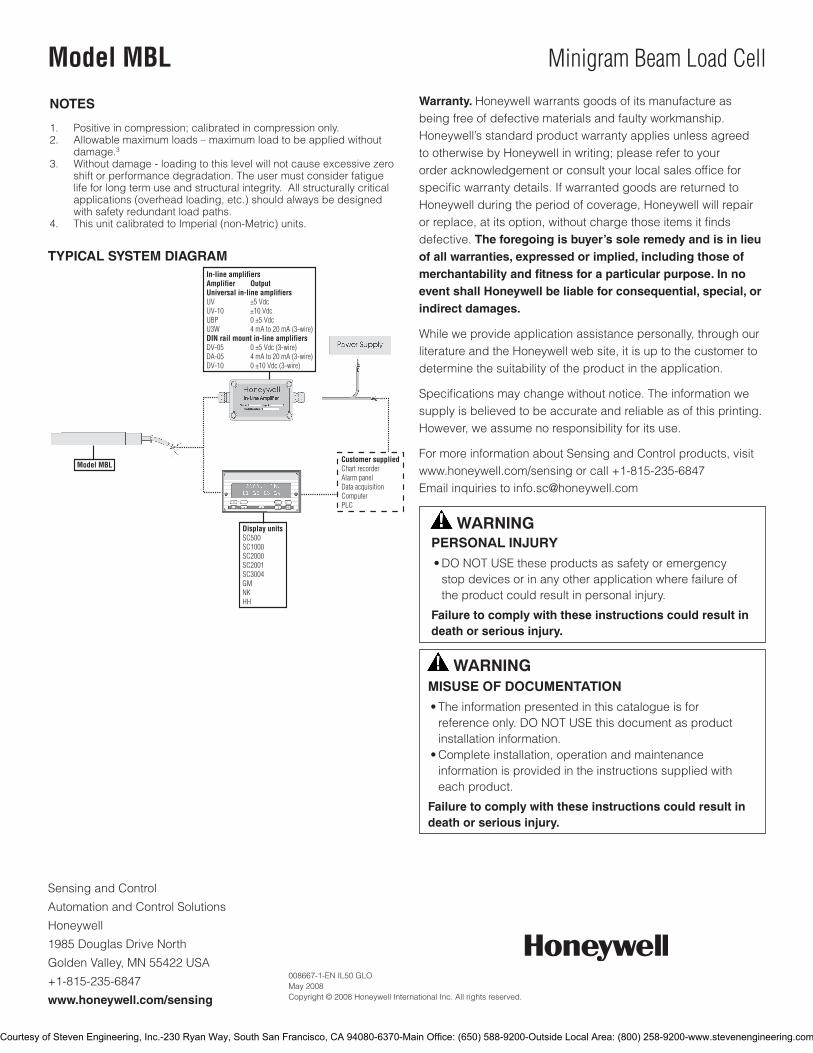
SensingandControl
AutomationandControlSolutions
Honeywell
1985 Douglas Drive North
GoldenValley,MN55422USA
+1-815-235-6847
www.honeywell.com/sensing
008667-1-EN IL50 GLO May 2008Copyright © 2008 Honeywell International Inc. All rights reserved.
Model MBL Minigram Beam Load Cell
TYPICAL SYSTEM DIAGRAM
NOTES
1. Positive in compression; calibrated in compression only.2. Allowable maximum loads – maximum load to be applied without
damage.3 3. Withoutdamage-loadingtothislevelwillnotcauseexcessivezero
shift or performance degradation. The user must consider fatigue life for long term use and structural integrity. All structurally critical applications (overhead loading, etc.) should always be designed with safety redundant load paths.
4. ThisunitcalibratedtoImperial(non-Metric)units.
Warranty. Honeywell warrants goods of its manufacture as being free of defective materials and faulty workmanship. Honeywell’s standard product warranty applies unless agreed to otherwise by Honeywell in writing; please refer to your orderacknowledgementorconsultyourlocalsalesofficeforspecificwarrantydetails.IfwarrantedgoodsarereturnedtoHoneywell during the period of coverage, Honeywell will repair orreplace,atitsoption,withoutchargethoseitemsitfindsdefective. The foregoing is buyer’s sole remedy and is in lieu of all warranties, expressed or implied, including those of merchantability and fitness for a particular purpose. In no event shall Honeywell be liable for consequential, special, or indirect damages.
While we provide application assistance personally, through our literature and the Honeywell web site, it is up to the customer to determine the suitability of the product in the application.
Specificationsmaychangewithoutnotice.Theinformationwesupply is believed to be accurate and reliable as of this printing. However, we assume no responsibility for its use.
FormoreinformationaboutSensingandControlproducts,visitwww.honeywell.com/sensing or call +1-815-235-6847Email inquiries to [email protected]
WARNINGPERSONAL INJURY•DONOTUSEtheseproductsassafetyoremergencystopdevicesorinanyotherapplicationwherefailureoftheproductcouldresultinpersonalinjury.
Failure to comply with these instructions could result in death or serious injury.
WARNINGMISUSE OF DOCUMENTATION•Theinformationpresentedinthiscatalogueisforreferenceonly.DONOTUSEthisdocumentasproductinstallationinformation.•Completeinstallation,operationandmaintenanceinformationisprovidedintheinstructionssuppliedwitheachproduct.
Failure to comply with these instructions could result in death or serious injury.
Courtesy of Steven Engineering, Inc.-230 Ryan Way, South San Francisco, CA 94080-6370-Main Office: (650) 588-9200-Outside Local Area: (800) 258-9200-www.stevenengineering.com
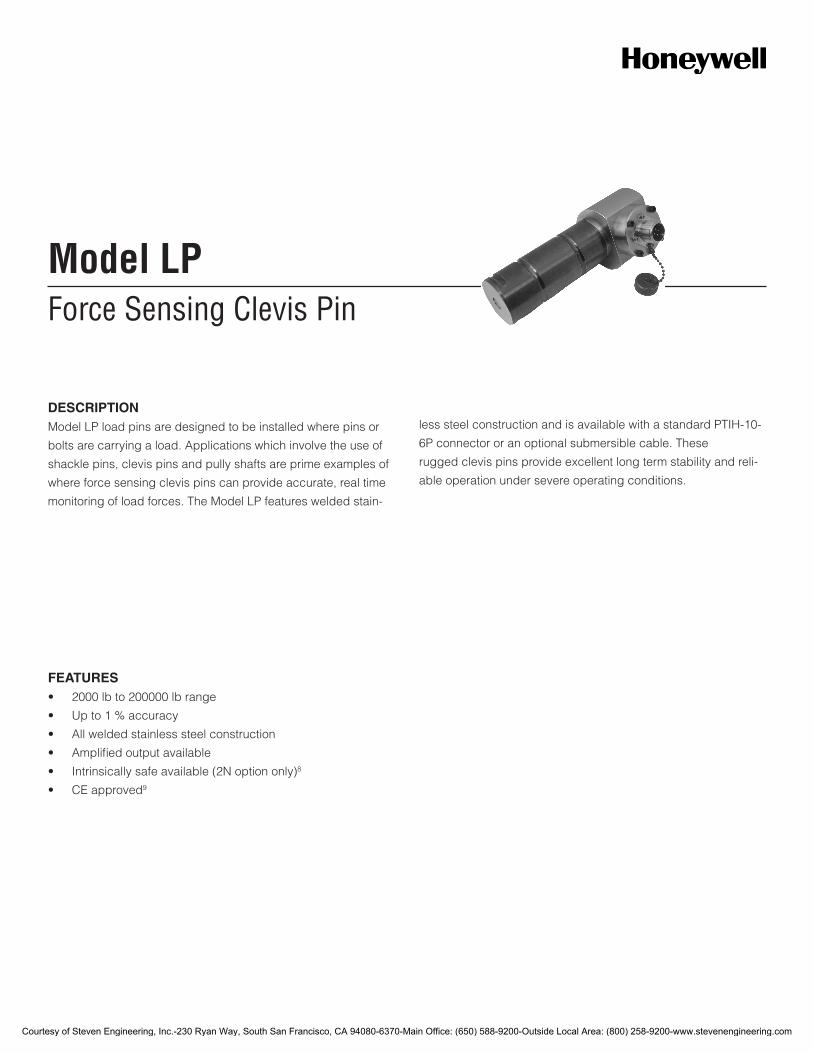
Force Sensing Clevis PinModel LP
DESCRIPTIONModel LP load pins are designed to be installed where pins or
bolts are carrying a load. Applications which involve the use of
shackle pins, clevis pins and pully shafts are prime examples of
where force sensing clevis pins can provide accurate, real time
monitoring of load forces. The Model LP features welded stain-
less steel construction and is available with a standard PTIH-10-
6P connector or an optional submersible cable. These
rugged clevis pins provide excellent long term stability and reli-
able operation under severe operating conditions.
FEATURES• 2000lbto200000lbrange
• Upto1%accuracy
• Allweldedstainlesssteelconstruction
• Amplifiedoutputavailable
• Intrinsicallysafeavailable(2Noptiononly)8
• CEapproved9
Courtesy of Steven Engineering, Inc.-230 Ryan Way, South San Francisco, CA 94080-6370-Main Office: (650) 588-9200-Outside Local Area: (800) 258-9200-www.stevenengineering.com
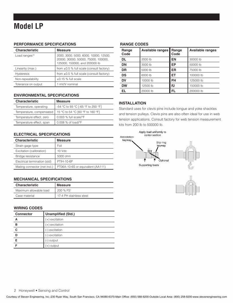
2Honeywell•SensingandControl
Model LP
PERFORMANCE SPECIFICATIONS
Characteristic Measure
Load ranges10 2000,3000,5000,6000,10000,12500,20000,30000,50000,75000,100000,125000,150000,and200000lb
Linearity(max.) from±0.5%fullscale(consultfactory)
Hysteresis from±0.5%fullscale(consultfactory)
Non-repeatability ±0.15%fullscale
Tolerance on output 1 mV/V nominal
ENVIRONMENTAL SPECIFICATIONS
Characteristic Measure
Temperature, operating -54°Cto93°C[-65°Fto250°F]
Temperature, compensated 15°Cto54°C[60°Fto160°F]
Temperature effect, zero 0.003%fullscale/°F
Temperature effect, span 0.008%ofload/°F
ELECTRICAL SPECIFICATIONS
Characteristic Measure
Straingagetype Foil
Excitation(calibration) 10 Vdc
Bridge resistance 5000ohm
Electricaltermination(std) PTIH-10-6P
Matingconnector(notincl.) PT06A-10-6Sorequivalent(AA111)
MECHANICAL SPECIFICATIONS
Characteristic Measure
Maximum allowable load 200%FS1
Casematerial 17-4PHstainlesssteel
RANGE CODES
Range Code
Available ranges Range Code
Available ranges
DL 2000lb EN 30000lb
DN 3000lb EP 50000lb
DR 5000lb ER 75000lb
DS 6000 lb ET 100000 lb
DV 10000 lb FH 125000lb
DW 12500lb FJ 150000lb
EL 20000lb FL 200000lb
WIRING CODES
Connector Unamplified (Std.)
A (+)excitation
B (+)excitation
C (-)excitation
D (-)excitation
E (-)output
F (+)output
INSTALLATIONStandardusesforclevispinsincludetongueandyokeshackles
andtensionpulleys.Clevispinsarealsooftenidealforuseinweb
tensionapplications.Consultfactoryforwebtensionmeasurement
kitsfrom200lbto500000lb.
Courtesy of Steven Engineering, Inc.-230 Ryan Way, South San Francisco, CA 94080-6370-Main Office: (650) 588-9200-Outside Local Area: (800) 258-9200-www.stevenengineering.com
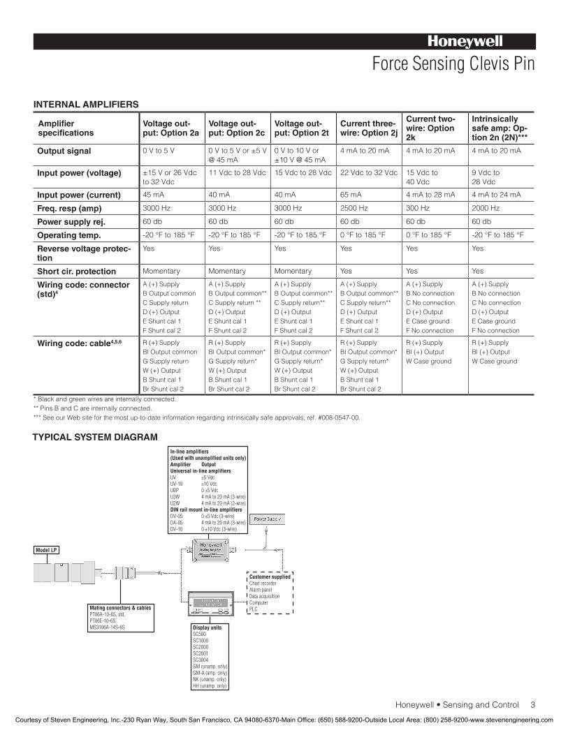
Honeywell•SensingandControl3
Force Sensing Clevis Pin
INTERNAL AMPLIFIERS
Amplifier specifications
Voltage out-put: Option 2a
Voltage out-put: Option 2c
Voltage out-put: Option 2t
Current three-wire: Option 2j
Current two-wire: Option 2k
Intrinsically safe amp: Op-tion 2n (2N)***
Output signal 0Vto5V 0Vto5Vor±5V@45mA
0 V to 10 V or ±10V@45mA
4mAto20mA 4mAto20mA 4mAto20mA
Input power (voltage) ±15Vor26Vdcto32Vdc
11Vdcto28Vdc 15Vdcto28Vdc 22Vdcto32Vdc 15Vdcto 40Vdc
9 Vdc to 28Vdc
Input power (current) 45mA 40mA 40mA 65mA 4mAto28mA 4mAto24mA
Freq. resp (amp) 3000Hz 3000Hz 3000Hz 2500Hz 300Hz 2000Hz
Power supply rej. 60 db 60 db 60 db 60 db 60 db 60 db
Operating temp. -20°Fto185°F -20°Fto185°F -20°Fto185°F 0°Fto185°F 0°Fto185°F -20°Fto185°F
Reverse voltage protec-tion
Yes Yes Yes Yes Yes Yes
Short cir. protection Momentary Momentary Momentary Yes Yes Yes
Wiring code: connector (std)4
A(+)SupplyB Output commonCSupplyreturnD(+)OutputEShuntcal1FShuntcal2
A(+)SupplyB Output common**CSupplyreturn**D(+)OutputEShuntcal1FShuntcal2
A(+)SupplyB Output common**CSupplyreturn**D(+)OutputEShuntcal1FShuntcal2
A(+)SupplyB Output common**CSupplyreturn**D(+)OutputEShuntcal1FShuntcal2
A(+)SupplyBNoconnectionCNoconnectionD(+)OutputECasegroundFNoconnection
A(+)SupplyBNoconnectionCNoconnectionD(+)OutputECasegroundFNoconnection
Wiring code: cable4,5,6 R(+)SupplyBl Output commonGSupplyreturnW(+)OutputBShuntcal1BrShuntcal2
R(+)SupplyBl Output common*GSupplyreturn*W(+)OutputBShuntcal1BrShuntcal2
R(+)SupplyBl Output common*GSupplyreturn*W(+)OutputBShuntcal1BrShuntcal2
R(+)SupplyBl Output common*GSupplyreturn*W(+)OutputBShuntcal1BrShuntcal2
R(+)SupplyBl(+)OutputWCaseground
R(+)SupplyBl(+)OutputWCaseground
* Black and green wires are internally connected.**PinsBandCareinternallyconnected.***SeeourWebsiteforthemostup-to-dateinformationregardingintrinsicallysafeapprovals,ref.#008-0547-00.
TYPICAL SYSTEM DIAGRAM
Courtesy of Steven Engineering, Inc.-230 Ryan Way, South San Francisco, CA 94080-6370-Main Office: (650) 588-9200-Outside Local Area: (800) 258-9200-www.stevenengineering.com
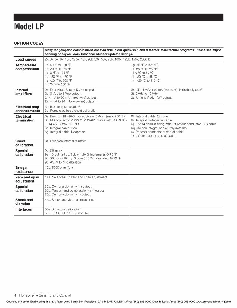
4Honeywell•SensingandControl
Model LP
OPTION CODES
Many range/option combinations are available in our quick-ship and fast-track manufacture programs. Please see http://sensing.honeywell.com/TMsensor-ship for updated listings.
Load ranges 2k,3k,5k,6k,10k,12.5k,15k,20k,30k,50k,75k,100k,125k,150k,200klb
Temperature compensation
1a.60°Fto160°F1b.30°Fto130°F1c.0°Fto185°F1d.-20°Fto130°F1e.-20°Fto200°F1f.70°Fto250°F
1g.70°Fto325°F3
1i.-65°Fto250°F3
1j.0°Cto50°C1k.-20°Cto85°C1m.-25°Cto110°C
Internal amplifiers
2a.Four-wire0Vdcto5Vdcoutput2c.0Vdcto5Vdcoutput2j.4mAto20mA(three-wire)output2k.4mAto20mA(two-wire)output11
2n(2N)4mAto20mA(two-wire)intrinsicallysafe11
2t.0Vdcto10Vdc2u.Unamplified,mV/Voutput
Electrical amp enhancements
3a.Input/outputisolation2
3d.Remotebufferedshuntcalibration
Electrical termination
6a.BendixPTIH-10-6P(orequivalent)6-pin(max.250°F)6b.MSconnectorMS3102E-14S-6P(mateswithMS3106E-
14S-6S)(max.160°F)6f.Integralcable:PVC6g.Integralcable:Neoprene
6h.Integralcable:Silicone6i. Integral underwater cable6j.1/2-14conduitfittingwith5ftoffourconductorPVCcable6q.Moldedintegralcable:Polyurethane6v. Phoenix connector at end of cable15d.Connectoronendofcable
Shunt calibration
8a. Precision internal resistor3
Special calibration
9e.CEmark9a.10point(5up/5down)20%increments@70°F9b.20point(10up/10down)10%increments@70°F9c.ASTME-74calibration
Bridge resistance
12b.5000ohm(foil)
Zero and span adjustment
14a.Noaccesstozeroandspanadjustment
Special calibration
30a.Compressiononly(+)output30b.Tensionandcompression(+,-)output30c.Compressiononly(-)output
Shock and vibration
44a.Shockandvibrationresistance
Interfaces 53e.Signaturecalibration3
53t.TEDSIEEE1451.4module7
Courtesy of Steven Engineering, Inc.-230 Ryan Way, South San Francisco, CA 94080-6370-Main Office: (650) 588-9200-Outside Local Area: (800) 258-9200-www.stevenengineering.com
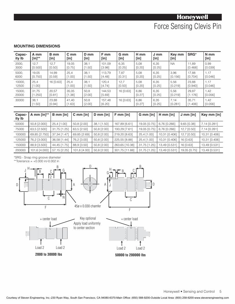
Honeywell•SensingandControl5
Force Sensing Clevis Pin
MOUNTING DIMENSIONS
Capac-ity lb
A mm [in]**
B mm [in]
C mm [in]
D mm [in]
F mm [in]
G mm [in]
H mm [in]
J mm [in]
Key mm [in]
SRG* N mm [in]
2000,3000
12,7[0.500]
12,7[0.50]
19,05[0.75]
38,1[1.50]
101,09 [3.98]
6,35[0.25]
5,08[0.20]
6,35[0.25]
NA 11,89 [0.468]
0,99 [0.039]
5000,6000
19,05[0.750]
14,99[0.59]
25,4[1.00]
38,1[1.50]
113,79[4.48]
7,87[0.31]
5,08[0.20]
6,35[0.25]
3,96[0.156]
17,88[0.704]
1,17[0.046]
10000, 12500
25,4[1.00]
16[0.63] 25,4[1.00]
38,1[1.50]
120,4[4.74]
12,7[0.50]
5,08[0.20]
6,35[0.25]
5,56[0.219]
23,88[0.940]
1,17[0.046]
15000,20000
31,75[1.250]
20,57[0.81]
35,05[1.38]
50,8[2.00]
144,53[5.69]
16[0.63] 6,86 [0.27]
6,35[0.25]
5,56[0.219]
29,87[1.176]
1,42[0.056]
30000 38,1[1.50]
23,88[0.94]
41,40[1.63]
50,8[2.00]
157,48[6.20]
16[0.63] 6,86 [0.27]
6,35[0.25]
7,14[0.281]
35,71[1.406]
1,42[0.056]
Capac-ity lb
A mm [in]** B mm [in] C mm [in] D mm [in] F mm [in] G mm [in] H mm [in] J mm [in] Key mm [in]
50000 50,8[2.000] 25,4[1.00] 50,8[2.00] 38,1[1.50] 167,89[6.61] 19,05[0.75] 6,76[0.266] 9,65[0.38] 7,14[0.281]
75000 63,5[2.500] 31,75[1.25] 63,5[2.50] 50,8[2.00] 193,29[7.61] 19,05[0.75] 6,76[0.266] 12,7[0.50] 7,14[0.281]
100000 69,85[2.750] 37,34[1.47] 69,85[2.69] 50,8[2.00] 219,20[8.63] 25,4[1.00] 10,31[0.406] 12,7[0.50] 10,31[0.406]
125000 76,2[3.000] 36,58[1.44] 76,2[3.00] 50,8[2.00] 225,55[8.88] 25,4[1.00] 10,31[0.406] 16[0.63] 10,31[0.406]
150000 88,9[3.500] 44,45[1.75] 88,9[3.50] 50,8[2.00] 263,65[10.38] 31,75[1.25] 13,49[0.531] 16[0.63] 13,49[0.531]
200000 101,6[4.000] 57,15[2.25] 101,6[4.00] 50,8[2.00] 301,75[11.88] 31,75[1.25] 13,49[0.531] 19,05[0.75] 13,49[0.531]
*SRG-Snapringgroovediameter**Tolerance=+0.000in/-0.002in
Courtesy of Steven Engineering, Inc.-230 Ryan Way, South San Francisco, CA 94080-6370-Main Office: (650) 588-9200-Outside Local Area: (800) 258-9200-www.stevenengineering.com
SensingandControl
AutomationandControlSolutions
Honeywell
1985DouglasDriveNorth
GoldenValley,MN55422USA
+1-815-235-6847
www.honeywell.com/sensing
008669-1-EN IL50 GLO May 2008Copyright © 2008 Honeywell International Inc. All rights reserved.
Model LP Force Sensing Clevis Pin
Warranty. Honeywell warrants goods of its manufacture as being free of defective materials and faulty workmanship. Honeywell’s standard product warranty applies unless agreed to otherwise by Honeywell in writing; please refer to your orderacknowledgementorconsultyourlocalsalesofficeforspecificwarrantydetails.IfwarrantedgoodsarereturnedtoHoneywell during the period of coverage, Honeywell will repair orreplace,atitsoption,withoutchargethoseitemsitfindsdefective. The foregoing is buyer’s sole remedy and is in lieu of all warranties, expressed or implied, including those of merchantability and fitness for a particular purpose. In no event shall Honeywell be liable for consequential, special, or indirect damages.
While we provide application assistance personally, through our literature and the Honeywell web site, it is up to the customer to determine the suitability of the product in the application.
Specificationsmaychangewithoutnotice.Theinformationwesupply is believed to be accurate and reliable as of this printing. However, we assume no responsibility for its use.
FormoreinformationaboutSensingandControlproducts,visitwww.honeywell.com/sensingorcall+1-815-235-6847Emailinquiriestoinfo.sc@honeywell.com
WARNINGPERSONAL INJURY•DONOTUSEtheseproductsassafetyoremergencystopdevicesorinanyotherapplicationwherefailureoftheproductcouldresultinpersonalinjury.
Failure to comply with these instructions could result in death or serious injury.
WARNINGMISUSE OF DOCUMENTATION•Theinformationpresentedinthiscatalogueisforreferenceonly.DONOTUSEthisdocumentasproductinstallationinformation.•Completeinstallation,operationandmaintenanceinformationisprovidedintheinstructionssuppliedwitheachproduct.
Failure to comply with these instructions could result in death or serious injury.
NOTES
1. Allowable maximum loads – Maximum load to be applied without damage.
2. Onlyavailablewithoption2bor2c.3. Notavailablewithamplifiedoption.4. Interconnectingshuntcal.1terminalwithshuntcal.2terminal
provides50%(unamplifiedunits),75%(4mAto20mAthree-wireunits)or80%(voltageamplifiedunits)offullscaleoutputforquickcalibration.Shuntcalibrationcomesstandardwithinternalamplifieroption2a,2b,2c,2tand2j.
5. O=Orange;Y=Yellow;B=Blue;Bl=Black;R=Red;Br=Brown;W=White;G=Green.Colorspecifyingcableandnumberorletterspecifying connector.
6. Nomatingconnectornecessaryforcableoption.7.ConsultfactoryforTEDSavailabilitywithamplifiedmodels.8. Range dependent; consult factory. Termination dependent; consult
factory.9. Internal amp and termination dependent; consult factory.10. ThisunitcalibratedtoImperial(non-Metric)units.11. 5000ohmbridgerequired.
Courtesy of Steven Engineering, Inc.-230 Ryan Way, South San Francisco, CA 94080-6370-Main Office: (650) 588-9200-Outside Local Area: (800) 258-9200-www.stevenengineering.com