Embed Size (px)
Citation preview
SmartLine
SLG 700 SmartLine Guided-Wave Radar
Level Specification
34-SL-03-03, February 2017
Technical Information
Introduction
Part of the SmartLine® family of products, the SLG 700
series level transmitters feature high performance guided
wave radar level technology. They provide high accuracy,
stability, and applicability suitable for a variety of level and
interface applications. SmartLine SLG 700 level transmitters
are ideally suited for your demanding process tank level
needs.
The SmartLine Level transmitter features the same powerful
features with the other transmitters in the SmartLine family
including modular design, polarity insensitivity, transmitter
messaging, tamper notification, and integration with
Experion® PKS thus providing the highest level of
compatibility assurance and integration capabilities.
A new SmartLine Application and Validation Tool provides a
new level of user experience and increases engineering
productivity.
Best in Class Features:
o Two-wire, loop-powered 4-20 mA transmitter
o Accuracy ±3 mm or 0.03% of measured distance
whichever is greater
o Repeatability ±1mm
o Integral dual seal design for safety based on
ANSI/NFPA 70-202 and ANSI/ISA 12.27.01
o Process Temperature range: -60 to 450C
o Process Pressure range: -1 to 400 bar
o Wetted parts include SS316L or Hastelloy-C (C-276)
o Automatic temperature compensation
o Advanced local display and local push buttons
(optional)
o Polarity insensitive electrical connections
o Comprehensive on-board diagnostic capabilities
o Full compliance to SIL 2/3 requirements as a standard
o Modular design
o Dual compartment design
o 3m remote mount housing (optional)
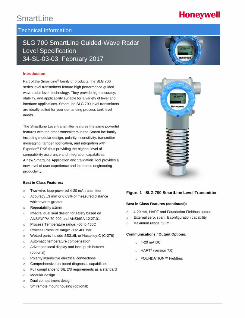
Figure 1 - SLG 700 SmartLine Level Transmitter
Best in Class Features (continued):
o 4-20 mA, HART and Foundation Fieldbus output
o External zero, span, & configuration capability
o Maximum range: 50 m
Communications / Output Options:
o 4-20 mA DC
o HART® (version 7.0)
o FOUNDATION™ Fieldbus
2 SLG 700 SmartLine Level Transmitter
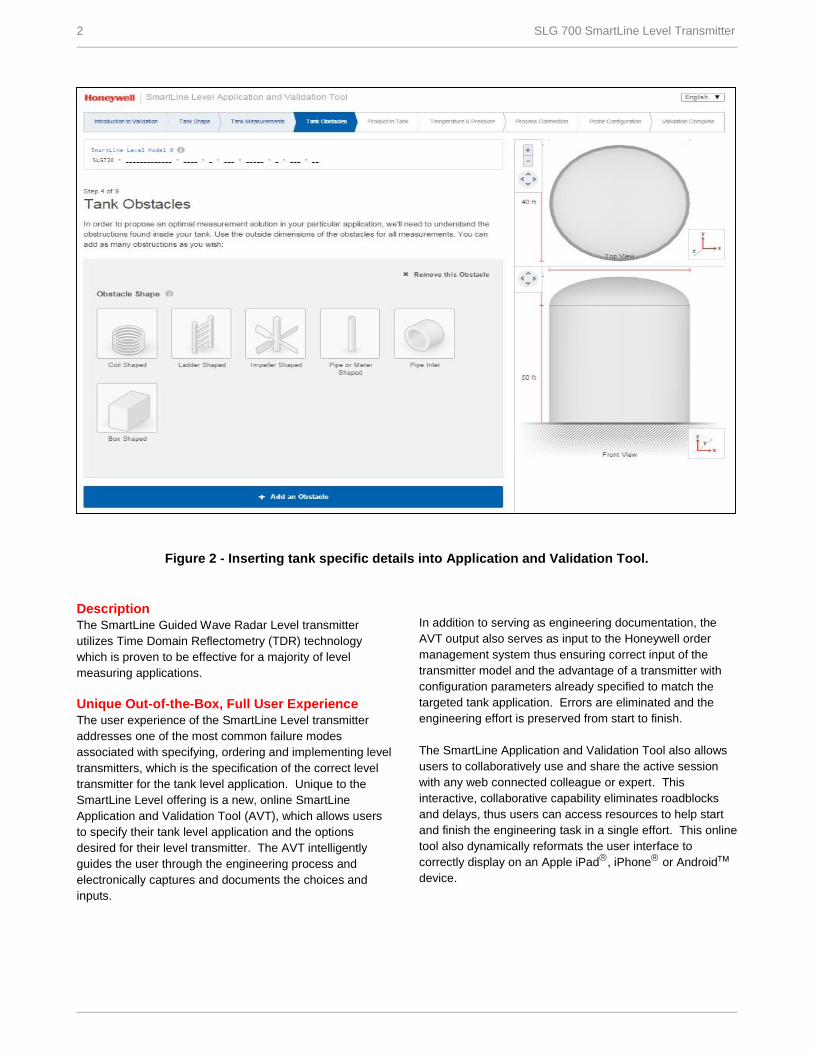
Figure 2 - Inserting tank specific details into Application and Validation Tool.
Description
The SmartLine Guided Wave Radar Level transmitter
utilizes Time Domain Reflectometry (TDR) technology
which is proven to be effective for a majority of level
measuring applications.
Unique Out-of-the-Box, Full User Experience
The user experience of the SmartLine Level transmitter
addresses one of the most common failure modes
associated with specifying, ordering and implementing level
transmitters, which is the specification of the correct level
transmitter for the tank level application. Unique to the
SmartLine Level offering is a new, online SmartLine
Application and Validation Tool (AVT), which allows users
to specify their tank level application and the options
desired for their level transmitter. The AVT intelligently
guides the user through the engineering process and
electronically captures and documents the choices and
inputs.
In addition to serving as engineering documentation, the
AVT output also serves as input to the Honeywell order
management system thus ensuring correct input of the
transmitter model and the advantage of a transmitter with
configuration parameters already specified to match the
targeted tank application. Errors are eliminated and the
engineering effort is preserved from start to finish.
The SmartLine Application and Validation Tool also allows
users to collaboratively use and share the active session
with any web connected colleague or expert. This
interactive, collaborative capability eliminates roadblocks
and delays, thus users can access resources to help start
and finish the engineering task in a single effort. This online
tool also dynamically reformats the user interface to
correctly display on an Apple iPad, iPhone or Android
device.
SLG 700 SmartLine Level Transmitter 3
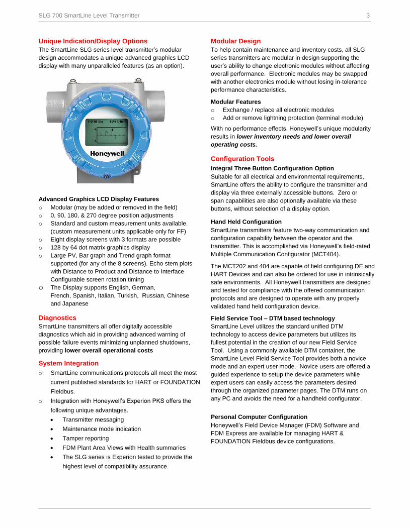
Unique Indication/Display Options
The SmartLine SLG series level transmitter’s modular
design accommodates a unique advanced graphics LCD
display with many unparalleled features (as an option).
Advanced Graphics LCD Display Features
o Modular (may be added or removed in the field)
o 0, 90, 180, & 270 degree position adjustments
o Standard and custom measurement units available.
(custom measurement units applicable only for FF)
o Eight display screens with 3 formats are possible
o 128 by 64 dot matrix graphics display
o Large PV, Bar graph and Trend graph format
supported (for any of the 8 screens). Echo stem plots
with Distance to Product and Distance to Interface
Configurable screen rotation timing
o The Display supports English, German,
French, Spanish, Italian, Turkish, Russian, Chinese
and Japanese
Diagnostics
SmartLine transmitters all offer digitally accessible
diagnostics which aid in providing advanced warning of
possible failure events minimizing unplanned shutdowns,
providing lower overall operational costs
System Integration
o SmartLine communications protocols all meet the most
current published standards for HART or FOUNDATION
Fieldbus.
o Integration with Honeywell’s Experion PKS offers the
following unique advantages.
Transmitter messaging
Maintenance mode indication
Tamper reporting
FDM Plant Area Views with Health summaries
The SLG series is Experion tested to provide the
highest level of compatibility assurance.
Modular Design
To help contain maintenance and inventory costs, all SLG
series transmitters are modular in design supporting the
user’s ability to change electronic modules without affecting
overall performance. Electronic modules may be swapped
with another electronics module without losing in-tolerance
performance characteristics.
Modular Features
o Exchange / replace all electronic modules
o Add or remove lightning protection (terminal module)
With no performance effects, Honeywell’s unique modularity
results in lower inventory needs and lower overall
operating costs.
Configuration Tools
Integral Three Button Configuration Option
Suitable for all electrical and environmental requirements,
SmartLine offers the ability to configure the transmitter and
display via three externally accessible buttons. Zero or
span capabilities are also optionally available via these
buttons, without selection of a display option.
Hand Held Configuration
SmartLine transmitters feature two-way communication and
configuration capability between the operator and the
transmitter. This is accomplished via Honeywell’s field-rated
Multiple Communication Configurator (MCT404).
The MCT202 and 404 are capable of field configuring DE and
HART Devices and can also be ordered for use in intrinsically
safe environments. All Honeywell transmitters are designed
and tested for compliance with the offered communication
protocols and are designed to operate with any properly
validated hand held configuration device.
Field Service Tool – DTM based technology
SmartLine Level utilizes the standard unified DTM
technology to access device parameters but utilizes its
fullest potential in the creation of our new Field Service
Tool. Using a commonly available DTM container, the
SmartLine Level Field Service Tool provides both a novice
mode and an expert user mode. Novice users are offered a
guided experience to setup the device parameters while
expert users can easily access the parameters desired
through the organized parameter pages. The DTM runs on
any PC and avoids the need for a handheld configurator.
Personal Computer Configuration
Honeywell’s Field Device Manager (FDM) Software and
FDM Express are available for managing HART &
FOUNDATION Fieldbus device configurations.
4 SLG 700 SmartLine Level Transmitter
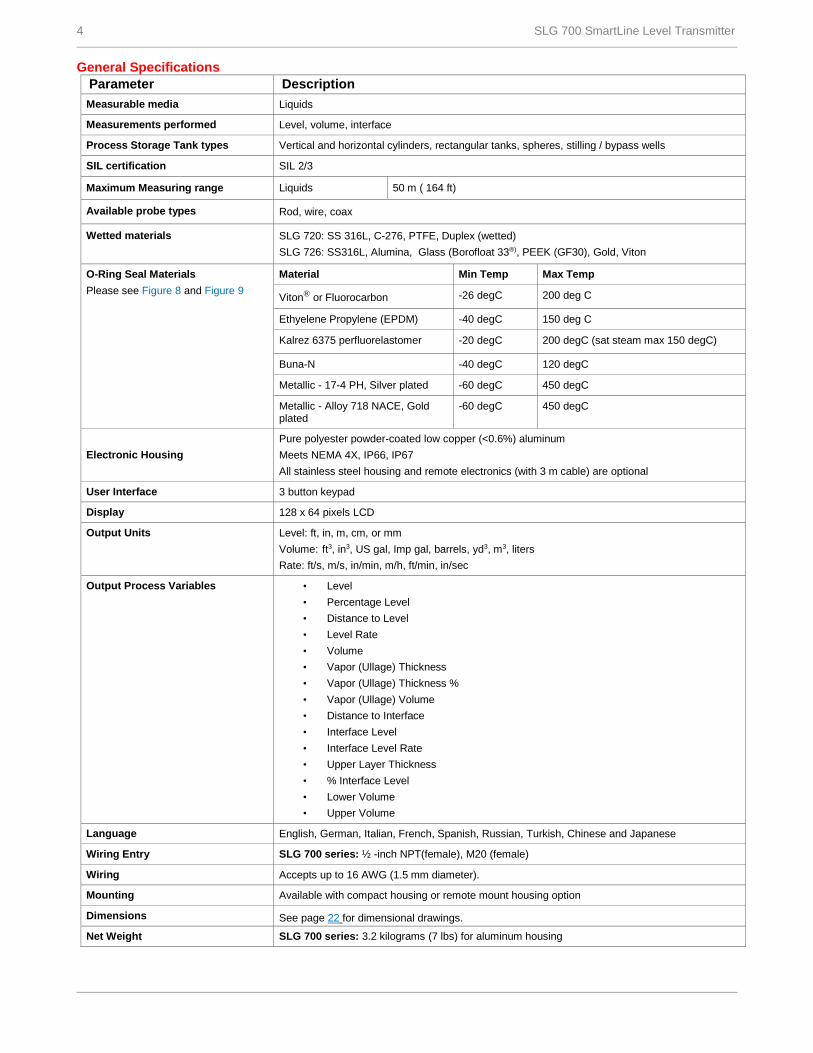
General Specifications
Parameter Description
Measurable media Liquids
Measurements performed Level, volume, interface
Process Storage Tank types Vertical and horizontal cylinders, rectangular tanks, spheres, stilling / bypass wells
SIL certification SIL 2/3
Maximum Measuring range Liquids 50 m ( 164 ft)
Available probe types Rod, wire, coax
Wetted materials SLG 720: SS 316L, C-276, PTFE, Duplex (wetted)
SLG 726: SS316L, Alumina, Glass (Borofloat 33®), PEEK (GF30), Gold, Viton
O-Ring Seal Materials
Please see Figure 8 and Figure 9
Material Min Temp Max Temp
Viton® or Fluorocarbon -26 degC 200 deg C
Ethyelene Propylene (EPDM) -40 degC 150 deg C
Kalrez 6375 perfluorelastomer -20 degC 200 degC (sat steam max 150 degC)
Buna-N -40 degC 120 degC
Metallic - 17-4 PH, Silver plated -60 degC 450 degC
Metallic - Alloy 718 NACE, Gold plated
-60 degC 450 degC
Electronic Housing
Pure polyester powder-coated low copper (<0.6%) aluminum
Meets NEMA 4X, IP66, IP67
All stainless steel housing and remote electronics (with 3 m cable) are optional
User Interface 3 button keypad
Display 128 x 64 pixels LCD
Output Units Level: ft, in, m, cm, or mm
Volume: ft3, in3, US gal, Imp gal, barrels, yd3, m3, liters
Rate: ft/s, m/s, in/min, m/h, ft/min, in/sec
Output Process Variables • Level
• Percentage Level
• Distance to Level
• Level Rate
• Volume
• Vapor (Ullage) Thickness
• Vapor (Ullage) Thickness %
• Vapor (Ullage) Volume
• Distance to Interface
• Interface Level
• Interface Level Rate
• Upper Layer Thickness
• % Interface Level
• Lower Volume
• Upper Volume
Language English, German, Italian, French, Spanish, Russian, Turkish, Chinese and Japanese
Wiring Entry SLG 700 series: ½ -inch NPT(female), M20 (female)
Wiring Accepts up to 16 AWG (1.5 mm diameter).
Mounting Available with compact housing or remote mount housing option
Dimensions See page 22 for dimensional drawings.
Net Weight SLG 700 series: 3.2 kilograms (7 lbs) for aluminum housing

SLG 700 SmartLine Level Transmitter 5
Operating Conditions – All Models
Parameter Rated Condition Operative Limits Transportation and Storage
C F C F C F
Ambient Temperature1 -40 to 85 -40 to 185 -40 to 85 -40 to 185 -55 to 120 -67 to 248
Process Connector2
SLG 720 -40 to 200 -40 to 392 -40 to 200 -40 to 392 -55 to 125 -67 to 257
SLG 726 -60 to 450 -76 to 842 -60 to 450 -76 to 842 -55 to 125 -67 to 257
Humidity %RH 0 to 100 0 to 100 0 to 100
Maximum Allowable Working
Pressure (MAWP) 3, 4 SLG720: 40 bar (580 psi)
SLG726: 400 bar (5800 psi) "See Figure 10 and Figure 11
Supply Voltage and Load Resistance
(HART)
Voltage at transmitter terminals is 14.0 to 42.0 Vdc (IS versions limited to 30 Vdc)
0 to 1284 ohms (as shown in
Figure 3). A minimum of 250ohms is required to support HART communications.
Supply Voltage
(FOUNDATION Fieldbus)
Voltage at transmitter terminals is 9.0 to 32.0 Vdc (IS versions limited to 30 Vdc, FISCO limited to
17.5 Vdc)
1 LCD Display operating temperature -20C to +70C . Storage temperature -30C to 80C.
2 Rated condition and operative limit temperatures subject to O-Ring selection and ambient temperature conditions.
3 Units can withstand overpressure of 1.5 x MAWP without damage
4 Consult factory for MAWP of SLG 700 transmitter with CRN approval
Figure 3 – Operating Voltage (Supply voltage) and maximum allowable loop resistance (not applicable for Fieldbus)
RLOOP MAX = maximum loop resistance (including safety barriers and wiring) that will allow proper Transmitter operation and is calculated as
RLOOP MAX = (VSUPPLY MIN – VXMTR MIN) 21.8 mA. Where: VXMTR MIN = 14V (Minimum Voltage at the terminals)
6 SLG 700 SmartLine Level Transmitter
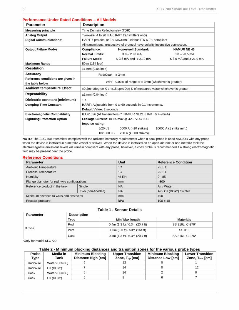
Performance Under Rated Conditions – All Models
Parameter Description
Measuring principle Time Domain Reflectometry (TDR)
Analog Output
Digital Communications:
Two-wire, 4 to 20 mA (HART transmitters only)
HART 7 protocol or FOUNDATION Fieldbus ITK 6.0.1 compliant
All transmitters, irrespective of protocol have polarity insensitive connection.
Output Failure Modes Compliance: Honeywell Standard: NAMUR NE 43
Normal Limits: 3.8 – 20.8 mA 3.8 – 20.5 mA
Failure Mode: ≤ 3.6 mA and ≥ 21.0 mA ≤ 3.6 mA and ≥ 21.0 mA
Maximum Range 50 m (164 feet)
Resolution ±1 mm (0.04 inch)
Accuracy
Reference conditions are given in
the table below
Rod/Coax ± 3mm
Wire 0.03% of range or ± 3mm (whichever is greater)
Ambient temperature Effect ±0.2mm/degree K or ±15 ppm/Deg K of measured value whichever is greater Repeatability ±1 mm (0.04 inch)
Dielectric constant (minimum) 1.4
Damping Time Constant HART: Adjustable from 0 to 60 seconds in 0.1 increments.
Default Value: 2 seconds
Electromagnetic Compatibility IEC61326 (All transmitters) *, NAMUR NE21 (HART & 4-20mA)
Lightning Protection Option
Leakage Current: 10 uA max @ 42.0 VDC 93C
Impulse rating:
8/20 uS 5000 A (>10 strikes) 10000 A (1 strike min.)
10/1000 uS 200 A (> 300 strikes)
NOTE: The SLG 700 transmitter complies with the radiated immunity requirements when a coax probe is used AND/OR with any probe
when the device is installed in a metallic vessel or stillwell. When the device is installed on an open-air tank or non-metallic tank the
electromagnetic emissions levels will remain compliant with any probe, however, a coax probe is recommended if a strong electromagnetic
field may be present near the probe.
Reference Conditions
Parameter Unit Reference Condition
Ambient Temperature C 25 ± 1
Process Temperature C 25 ± 1
Humidity % RH 0 - 85
Flange diameter for rod, wire configurations mm >300
Reference product in the tank Single NA Air / Water
Two (non-flooded) NA Air / Oil (DC=2) / Water
Minimum distance to walls and obstacles mm 400
Process pressure kPa 100 ± 10
Table 1 - Sensor Details
Parameter Description
Probe
Type Min/ Max length Materials
Rod 0.4m (1.3 ft) / 6.3m (20.7 ft) SS 316L, C-276*
Wire 1.0m (3.3 ft) / 50m (164 ft) SS 316
Coax 0.4m (1.3 ft) / 6.3m (20.7 ft) SS 316L, C-276*
*Only for model SLG720
Table 2 - Minimum blocking distances and transition zones for the various probe types
Probe Type
Media in Tank
Minimum Blocking Distance High [cm]
Upper Transition Zone, Tup [cm]
Minimum Blocking Distance Low [cm]
Lower Transition Zone, Tlow [cm]
Rod/Wire Water (DC=80) 9 13 0 1
Rod/Wire Oil (DC=2) 7 14 0 12
Coax Water (DC=80) 5 14 2 0
Coax Oil (DC=2) 5 8 6 7
SLG 700 SmartLine Level Transmitter 7
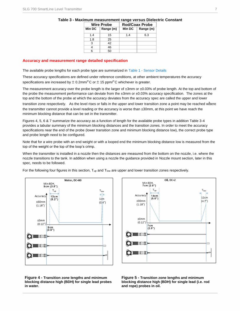
Table 3 - Maximum measurement range versus Dielectric Constant
Wire Probe Rod/Coax Probe Min DC Range (m) Min DC Range (m)
1.4 15 1.4 6.3
1.8 25
3 42
4 46
6 50
Accuracy and measurement range detailed specification
The available probe lengths for each probe type are summarized in Table 1 - Sensor Details
These accuracy specifications are defined under reference conditions, at other ambient temperatures the accuracy
specifications are increased by 0.2mm/C or 15 ppm/C whichever is greater.
The measurement accuracy over the probe length is the larger of ±3mm or ±0.03% of probe length. At the top and bottom of
the probe the measurement performance can deviate from the ±3mm or ±0.03% accuracy specification. The zones at the
top and the bottom of the probe at which the accuracy deviates from the accuracy spec are called the upper and lower
transition zone respectively. As the level rises or falls in the upper and lower transition zone a point may be reached where
the transmitter cannot provide a level reading or the accuracy is worse than ±30mm, at this point we have reach the
minimum blocking distance that can be set in the transmitter.
Figures 4, 5, 6 & 7 summarize the accuracy as a function of length for the available probe types in addition Table 3-4
provides a tabular summary of the minimum blocking distances and the transition zones. In order to meet the accuracy
specifications near the end of the probe (lower transition zone and minimum blocking distance low), the correct probe type
and probe length need to be configured.
Note that for a wire probe with an end weight or with a looped end the minimum blocking distance low is measured from the
top of the weight or the top of the loop’s crimp.
When the transmitter is installed in a nozzle then the distances are measured from the bottom on the nozzle, i.e. where the
nozzle transitions to the tank. In addition when using a nozzle the guidance provided in Nozzle mount section, later in this
spec, needs to be followed.
For the following four figures in this section, Tup and Tlow are upper and lower transition zones respectively.
Figure 4 - Transition zone lengths and minimum blocking distance high (BDH) for single lead probes in water.
Figure 5 - Transition zone lengths and minimum blocking distance high (BDH) for single lead (i.e. rod and rope) probes in oil.
8 SLG 700 SmartLine Level Transmitter
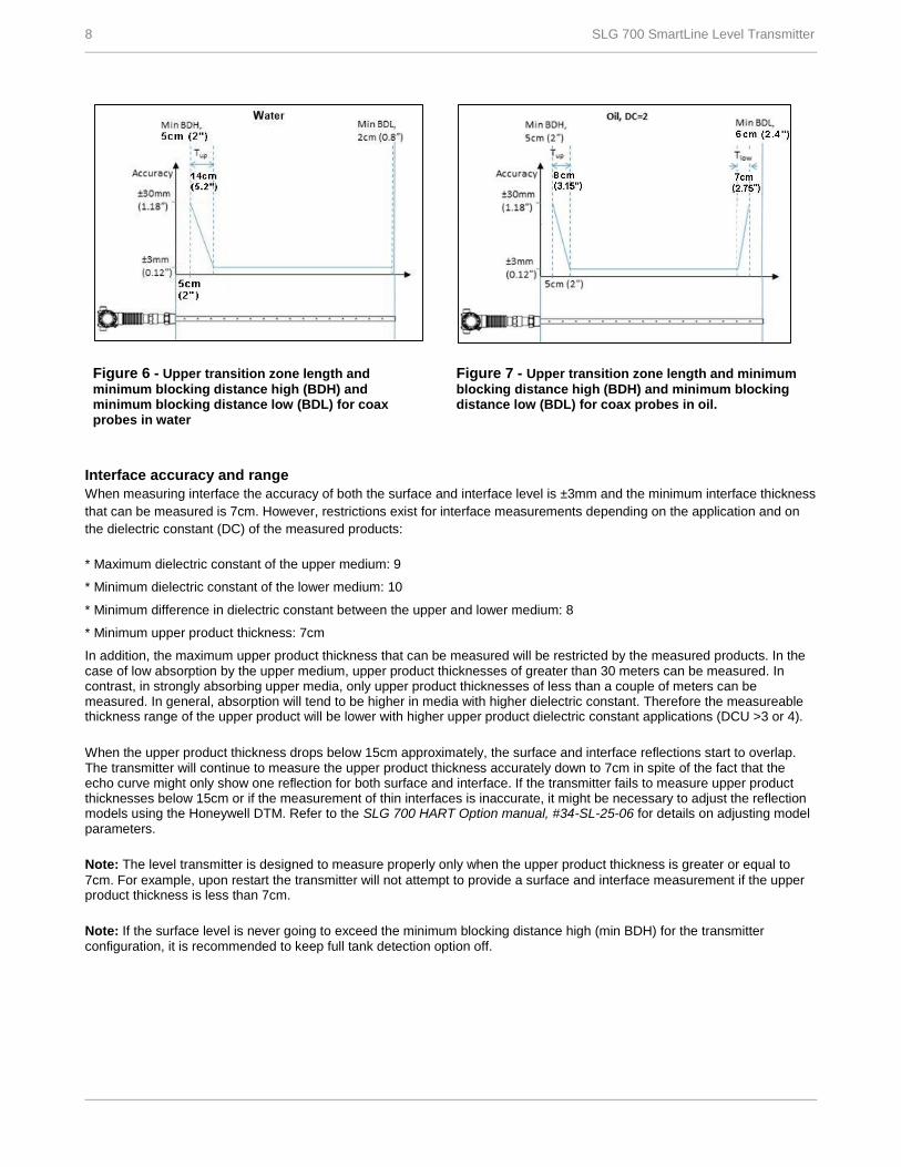
Figure 6 - Upper transition zone length and
minimum blocking distance high (BDH) and minimum blocking distance low (BDL) for coax probes in water
Figure 7 - Upper transition zone length and minimum
blocking distance high (BDH) and minimum blocking distance low (BDL) for coax probes in oil.
Interface accuracy and range
When measuring interface the accuracy of both the surface and interface level is ±3mm and the minimum interface thickness
that can be measured is 7cm. However, restrictions exist for interface measurements depending on the application and on
the dielectric constant (DC) of the measured products:
* Maximum dielectric constant of the upper medium: 9
* Minimum dielectric constant of the lower medium: 10
* Minimum difference in dielectric constant between the upper and lower medium: 8
* Minimum upper product thickness: 7cm
In addition, the maximum upper product thickness that can be measured will be restricted by the measured products. In the case of low absorption by the upper medium, upper product thicknesses of greater than 30 meters can be measured. In contrast, in strongly absorbing upper media, only upper product thicknesses of less than a couple of meters can be measured. In general, absorption will tend to be higher in media with higher dielectric constant. Therefore the measureable thickness range of the upper product will be lower with higher upper product dielectric constant applications (DCU >3 or 4).
When the upper product thickness drops below 15cm approximately, the surface and interface reflections start to overlap. The transmitter will continue to measure the upper product thickness accurately down to 7cm in spite of the fact that the echo curve might only show one reflection for both surface and interface. If the transmitter fails to measure upper product thicknesses below 15cm or if the measurement of thin interfaces is inaccurate, it might be necessary to adjust the reflection models using the Honeywell DTM. Refer to the SLG 700 HART Option manual, #34-SL-25-06 for details on adjusting model parameters.
Note: The level transmitter is designed to measure properly only when the upper product thickness is greater or equal to
7cm. For example, upon restart the transmitter will not attempt to provide a surface and interface measurement if the upper product thickness is less than 7cm.
Note: If the surface level is never going to exceed the minimum blocking distance high (min BDH) for the transmitter configuration, it is recommended to keep full tank detection option off.
SLG 700 SmartLine Level Transmitter 9
Centering Disk
Parameter Description
Centering Disk Type Min/ Max diameter Materials
Rod and Wire 5.08 cm (2 in) / 20.32 cm (8 in) SS 316L, C-276
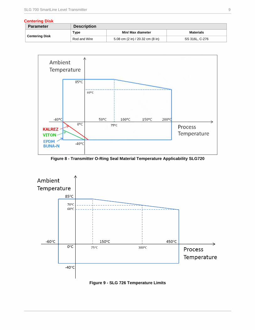
Figure 8 - Transmitter O-Ring Seal Material Temperature Applicability SLG720
Figure 9 - SLG 726 Temperature Limits
10 SLG 700 SmartLine Level Transmitter
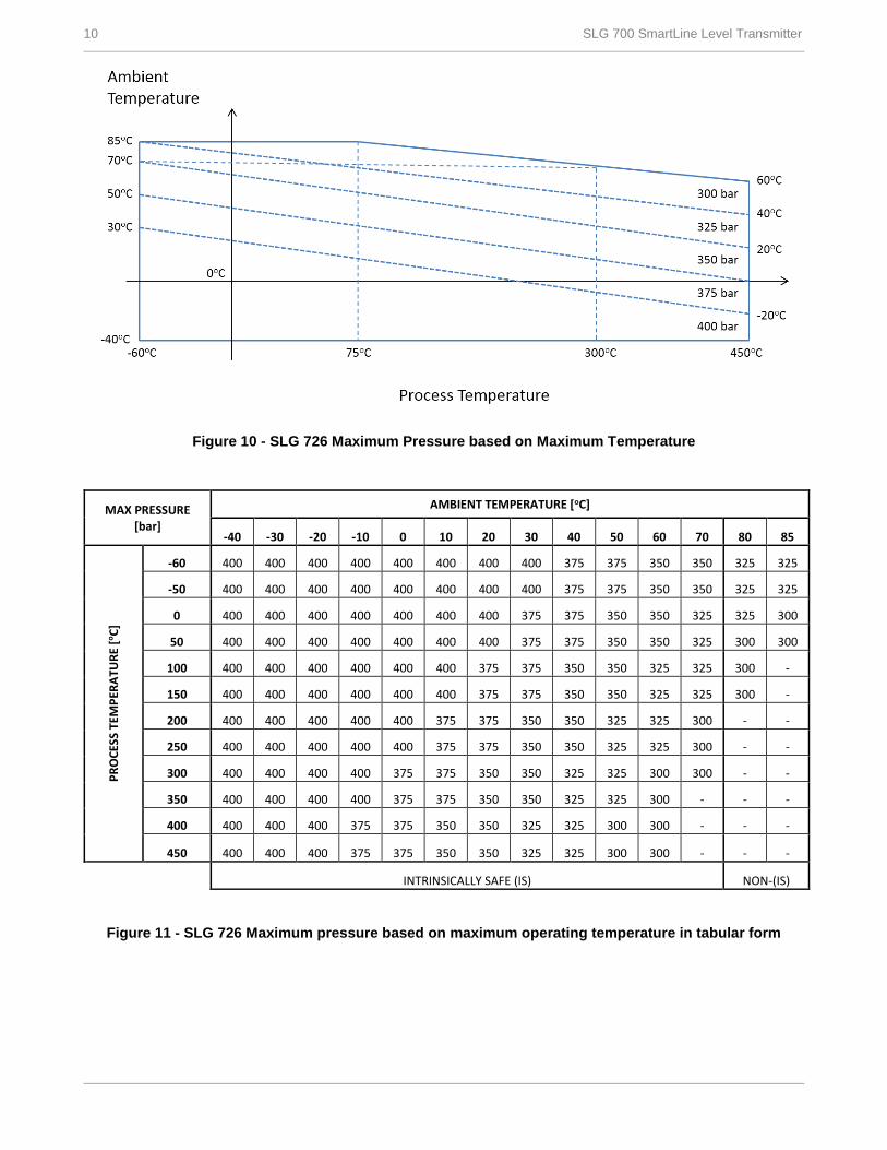
Figure 10 - SLG 726 Maximum Pressure based on Maximum Temperature
Figure 11 - SLG 726 Maximum pressure based on maximum operating temperature in tabular form
MAX PRESSURE [bar]
AMBIENT TEMPERATURE [oC]
-40 -30 -20 -10 0 10 20 30 40 50 60 70 80 85
PR
OC
ESS
TEM
PER
ATU
RE
[oC
]
-60 400 400 400 400 400 400 400 400 375 375 350 350 325 325
-50 400 400 400 400 400 400 400 400 375 375 350 350 325 325
0 400 400 400 400 400 400 400 375 375 350 350 325 325 300
50 400 400 400 400 400 400 400 375 375 350 350 325 300 300
100 400 400 400 400 400 400 375 375 350 350 325 325 300 -
150 400 400 400 400 400 400 375 375 350 350 325 325 300 -
200 400 400 400 400 400 375 375 350 350 325 325 300 - -
250 400 400 400 400 400 375 375 350 350 325 325 300 - -
300 400 400 400 400 375 375 350 350 325 325 300 300 - -
350 400 400 400 400 375 375 350 350 325 325 300 - - -
400 400 400 400 375 375 350 350 325 325 300 300 - - -
450 400 400 400 375 375 350 350 325 325 300 300 - - -
INTRINSICALLY SAFE (IS) NON-(IS)
SLG 700 SmartLine Level Transmitter 11
Communications Protocols & Diagnostics
HART Protocol
Version: HART 7
Power Supply
Voltage: 14.0 to 42.0 Vdc at terminals
Load: Maximum 1284 ohms. See Operating Conditions –
All Models table, Figure 3.
Minimum Load: 0 ohms. (For HART communications a
minimum load of 250 ohms is required)
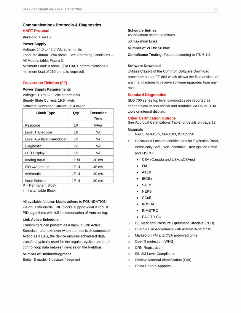
FOUNDATION Fieldbus (FF)
Power Supply Requirements
Voltage: 9.0 to 32.0 Vdc at terminals
Steady State Current: 19.6 mAdc
Software Download Current: 29.4 mAdc
Block Type Qty Execution
Time
Resource 1P NA/a
Level Transducer 1P NA
Level Auxillary Transducer 1P NA
Diagnostic 1P NA
LCD Display 1P NA
Analog Input 1P 5I 30 ms
PID w/Autotune 1P 1I 45 ms
Arithmetic 1P 1I 30 ms
Input Selector 1P 1I 30 ms
P = Permanent Block
I = Instantiable Block
All available function blocks adhere to FOUNDATION
Fieldbus standards. PID blocks support ideal & robust
PID algorithms with full implementation of Auto-tuning.
Link Active Scheduler
Transmitters can perform as a backup Link Active
Scheduler and take over when the host is disconnected.
Acting as a LAS, the device ensures scheduled data
transfers typically used for the regular, cyclic transfer of
control loop data between devices on the Fieldbus.
Number of Devices/Segment
Entity IS model: 6 devices / segment
Schedule Entries
45 maximum schedule entries
50 maximum Links
Number of VCRs: 50 max
Compliance Testing: Tested according to ITK 6.1.2
Software Download
Utilizes Class-3 of the Common Software Download
procedure as per FF-883 which allows the field devices of
any manufacturer to receive software upgrades from any
host.
Standard Diagnostics
SLG 700 series top level diagnostics are reported as
either critical or non-critical and readable via DD or DTM
tools or integral display.
Other Certification Options See Approval Certifications Table for details on page 12.
Materials
o NACE MRO175, MRO103, ISO15156
o Hazardous Location certifications for Explosion Proof,
Intrinsically Safe, Non-Incendive, Dust Ignition Proof,
and FISCO:
CSA (Canada and USA, cCSAus)
FM
ATEX
IECEx
SAEx
NEPSI
CCoE
KOSHA
INMETRO
EAC TR-CU
o CE Mark and Pressure Equipment Directive (PED)
o Dual Seal in Accordance with ANSI/ISA-12.27.01
o Marked on FM and CSA approved units
o Overfill protection (WHG)
o CRN Registration
o SIL 2/3 Level Compliance
o Positive Material Identification (PMI)
o China Pattern Approval
12 SLG 700 SmartLine Level Transmitter
Mounting recommendations
Suitable mounting position
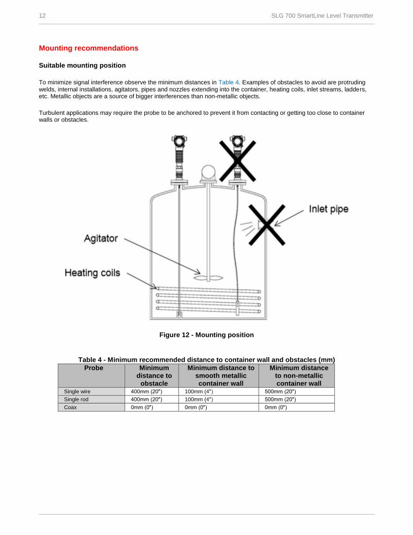
To minimize signal interference observe the minimum distances in Table 4. Examples of obstacles to avoid are protruding welds, internal installations, agitators, pipes and nozzles extending into the container, heating coils, inlet streams, ladders, etc. Metallic objects are a source of bigger interferences than non-metallic objects.
Turbulent applications may require the probe to be anchored to prevent it from contacting or getting too close to container walls or obstacles.
Figure 12 - Mounting position
Table 4 - Minimum recommended distance to container wall and obstacles (mm)
Probe Minimum distance to
obstacle
Minimum distance to smooth metallic container wall
Minimum distance to non-metallic container wall
Single wire 400mm (20″) 100mm (4″) 500mm (20″)
Single rod 400mm (20″) 100mm (4″) 500mm (20″)
Coax 0mm (0″) 0mm (0″) 0mm (0″)
SLG 700 SmartLine Level Transmitter 13
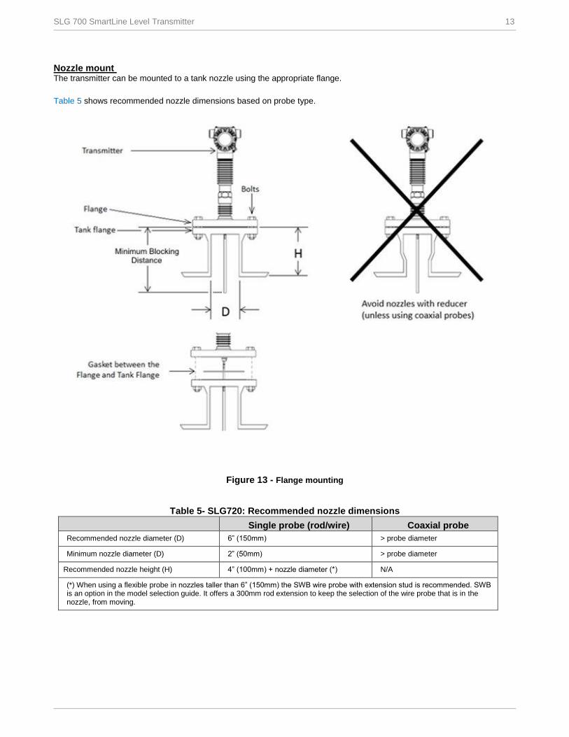
Nozzle mount The transmitter can be mounted to a tank nozzle using the appropriate flange.
Table 5 shows recommended nozzle dimensions based on probe type.
Figure 13 - Flange mounting
Table 5- SLG720: Recommended nozzle dimensions
Single probe (rod/wire) Coaxial probe
Recommended nozzle diameter (D) 6” (150mm) > probe diameter
Minimum nozzle diameter (D) 2” (50mm) > probe diameter
Recommended nozzle height (H) 4” (100mm) + nozzle diameter (*) N/A
(*) When using a flexible probe in nozzles taller than 6” (150mm) the SWB wire probe with extension stud is recommended. SWB is an option in the model selection guide. It offers a 300mm rod extension to keep the selection of the wire probe that is in the nozzle, from moving.
14 SLG 700 SmartLine Level Transmitter
In certain applications taller nozzles may be accommodated but near zone performance at the exit of the nozzle may be reduced. For nozzle dimensions that do not meet the requirements outlined in
Table 5 contact the Honeywell Technical Assistance Centre.
Area Organization Phone Number
United States and Canada Honeywell Inc.
1-800-343-0228 Customer Service
1-800-423-9883 Global Technical Support
Global Email Support Honeywell Process Solutions [email protected]
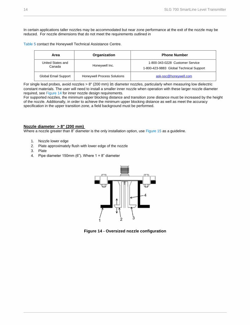
For single lead probes, avoid nozzles > 8" (200 mm) in diameter nozzles, particularly when measuring low dielectric
constant materials. The user will need to install a smaller inner nozzle when operation with these larger nozzle diameter required, see Figure 14 for inner nozzle design requirements. For supported nozzles, the minimum upper blocking distance and transition zone distance must be increased by the height of the nozzle. Additionally, in order to achieve the minimum upper blocking distance as well as meet the accuracy specification in the upper transition zone, a field background must be performed.
Nozzle diameter > 8" (200 mm) Where a nozzle greater than 8” diameter is the only installation option, use Figure 15 as a guideline.
1. Nozzle lower edge
2. Plate approximately flush with lower edge of the nozzle
3. Plate
4. Pipe diameter 150mm (6”). Where 1 = 8” diameter
Figure 14 - Oversized nozzle configuration
SLG 700 SmartLine Level Transmitter 15
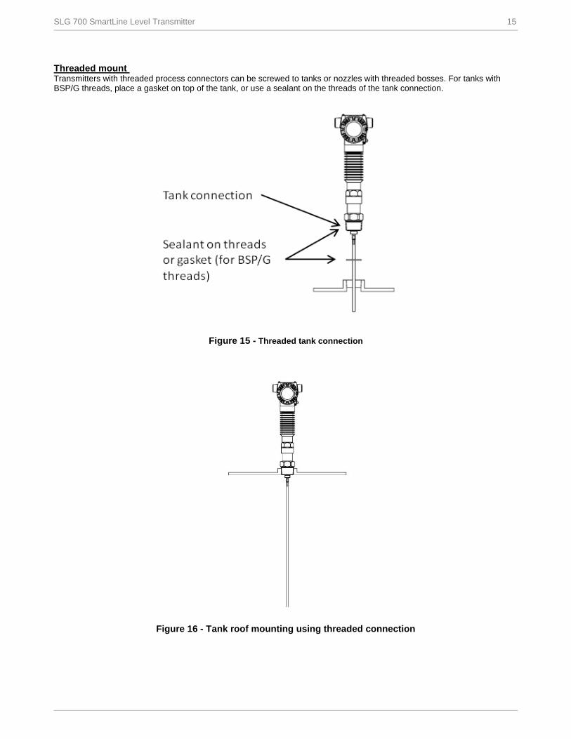
Threaded mount Transmitters with threaded process connectors can be screwed to tanks or nozzles with threaded bosses. For tanks with BSP/G threads, place a gasket on top of the tank, or use a sealant on the threads of the tank connection.
Figure 15 - Threaded tank connection
Figure 16 - Tank roof mounting using threaded connection
16 SLG 700 SmartLine Level Transmitter
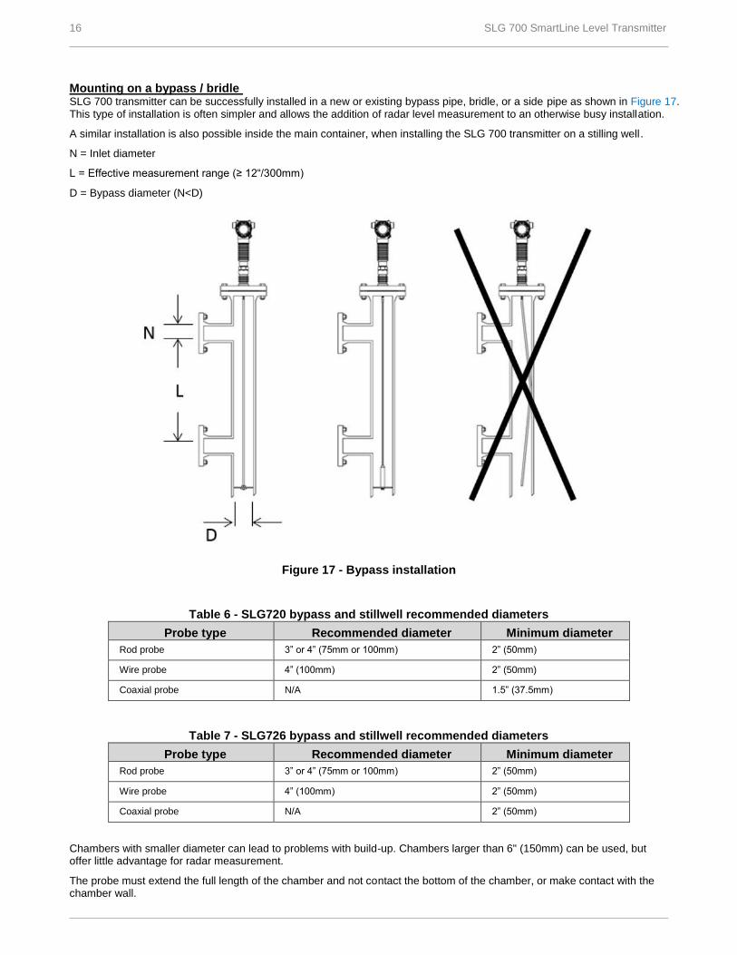
Mounting on a bypass / bridle SLG 700 transmitter can be successfully installed in a new or existing bypass pipe, bridle, or a side pipe as shown in Figure 17. This type of installation is often simpler and allows the addition of radar level measurement to an otherwise busy installation.
A similar installation is also possible inside the main container, when installing the SLG 700 transmitter on a stilling well.
N = Inlet diameter
L = Effective measurement range (≥ 12“/300mm)
D = Bypass diameter (N<D)
Figure 17 - Bypass installation
Table 6 - SLG720 bypass and stillwell recommended diameters
Probe type Recommended diameter Minimum diameter
Rod probe 3” or 4” (75mm or 100mm) 2” (50mm)
Wire probe 4” (100mm) 2” (50mm)
Coaxial probe N/A 1.5” (37.5mm)
Table 7 - SLG726 bypass and stillwell recommended diameters
Probe type Recommended diameter Minimum diameter
Rod probe 3” or 4” (75mm or 100mm) 2” (50mm)
Wire probe 4” (100mm) 2” (50mm)
Coaxial probe N/A 2” (50mm)
Chambers with smaller diameter can lead to problems with build-up. Chambers larger than 6" (150mm) can be used, but offer little advantage for radar measurement.
The probe must extend the full length of the chamber and not contact the bottom of the chamber, or make contact with the chamber wall.
SLG 700 SmartLine Level Transmitter 17
Clearance from the bottom of the chamber is recommended to be 1" (25mm). Probe selection is dependent on length.
For lengths less than 20′ 8″ (6.3m): Rod probe is recommended.
For lengths more than 20′ 8″ (6.3m): Wire probe with weight and centering disk is recommended.
A centering disc is recommended for rigid probes over 1m length to prevent excessive movement caused by strong currents inside the pipe.
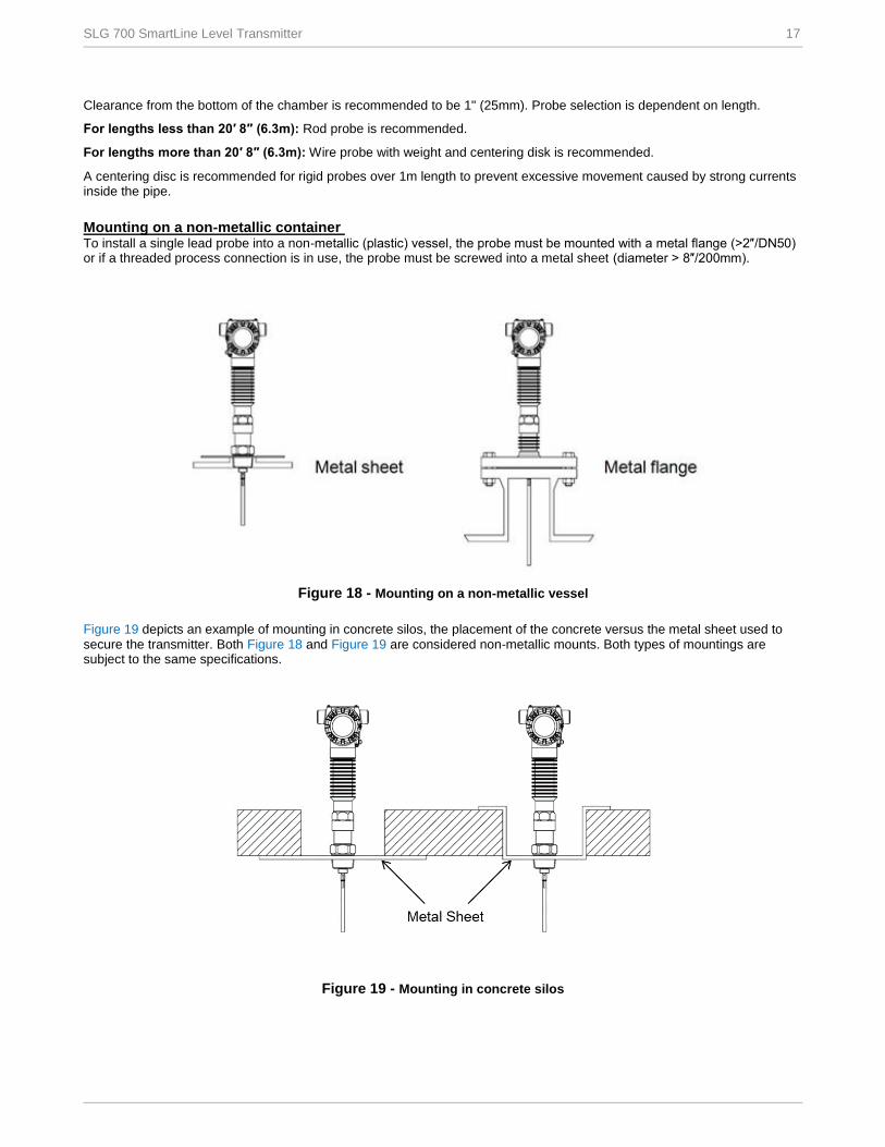
Mounting on a non-metallic container To install a single lead probe into a non-metallic (plastic) vessel, the probe must be mounted with a metal flange (>2″/DN50) or if a threaded process connection is in use, the probe must be screwed into a metal sheet (diameter > 8″/200mm).
Figure 18 - Mounting on a non-metallic vessel
Figure 19 depicts an example of mounting in concrete silos, the placement of the concrete versus the metal sheet used to secure the transmitter. Both Figure 18 and Figure 19 are considered non-metallic mounts. Both types of mountings are subject to the same specifications.
Figure 19 - Mounting in concrete silos
18 SLG 700 SmartLine Level Transmitter
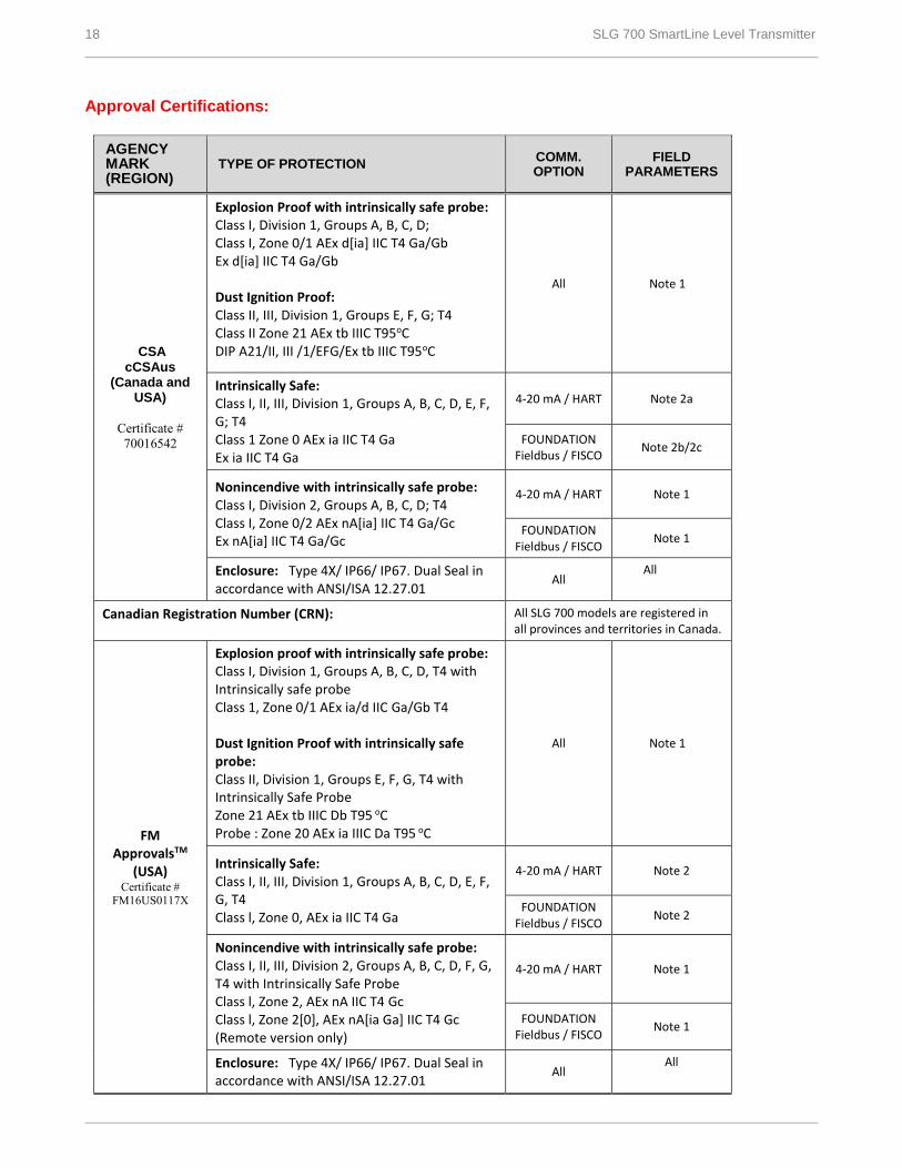
Approval Certifications:
AGENCY MARK (REGION)
TYPE OF PROTECTION COMM. OPTION
FIELD PARAMETERS
CSA cCSAus
(Canada and USA)
Certificate #
70016542
Explosion Proof with intrinsically safe probe: Class I, Division 1, Groups A, B, C, D; Class I, Zone 0/1 AEx d[ia] IIC T4 Ga/Gb Ex d[ia] IIC T4 Ga/Gb Dust Ignition Proof: Class II, III, Division 1, Groups E, F, G; T4 Class II Zone 21 AEx tb IIIC T95oC DIP A21/II, III /1/EFG/Ex tb IIIC T95oC
All Note 1
Intrinsically Safe: Class I, II, III, Division 1, Groups A, B, C, D, E, F, G; T4 Class 1 Zone 0 AEx ia IIC T4 Ga Ex ia IIC T4 Ga
4-20 mA / HART Note 2a
FOUNDATION Fieldbus / FISCO
Note 2b/2c
Nonincendive with intrinsically safe probe: Class I, Division 2, Groups A, B, C, D; T4 Class I, Zone 0/2 AEx nA[ia] IIC T4 Ga/Gc Ex nA[ia] IIC T4 Ga/Gc
4-20 mA / HART Note 1
FOUNDATION Fieldbus / FISCO
Note 1
Enclosure: Type 4X/ IP66/ IP67. Dual Seal in accordance with ANSI/ISA 12.27.01
All All
Canadian Registration Number (CRN): All SLG 700 models are registered in all provinces and territories in Canada.
FM ApprovalsTM
(USA) Certificate #
FM16US0117X
Explosion proof with intrinsically safe probe: Class I, Division 1, Groups A, B, C, D, T4 with Intrinsically safe probe Class 1, Zone 0/1 AEx ia/d IIC Ga/Gb T4 Dust Ignition Proof with intrinsically safe probe: Class II, Division 1, Groups E, F, G, T4 with Intrinsically Safe Probe Zone 21 AEx tb IIIC Db T95 oC Probe : Zone 20 AEx ia IIIC Da T95 oC
All Note 1
Intrinsically Safe: Class I, II, III, Division 1, Groups A, B, C, D, E, F, G, T4 Class l, Zone 0, AEx ia IIC T4 Ga
4-20 mA / HART Note 2
FOUNDATION Fieldbus / FISCO
Note 2
Nonincendive with intrinsically safe probe: Class I, II, III, Division 2, Groups A, B, C, D, F, G, T4 with Intrinsically Safe Probe Class l, Zone 2, AEx nA IIC T4 Gc Class l, Zone 2[0], AEx nA[ia Ga] IIC T4 Gc (Remote version only)
4-20 mA / HART Note 1
FOUNDATION Fieldbus / FISCO
Note 1
Enclosure: Type 4X/ IP66/ IP67. Dual Seal in accordance with ANSI/ISA 12.27.01
All All
SLG 700 SmartLine Level Transmitter 19
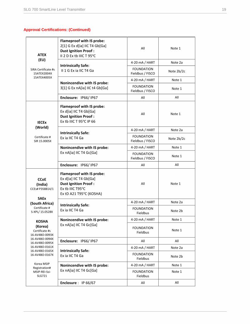
Approval Certifications: (Continued)
ATEX (EU)
SIRA Certificate #s 15ATEX2004X 15ATEX4005X
Flameproof with IS probe: 2[1] G Ex d[ia] IIC T4 Gb[Ga] Dust Ignition Proof : II 2 D Ex tb IIIC T 95oC
All Note 1
Intrinsically Safe: II 1 G Ex ia IIC T4 Ga
4-20 mA / HART Note 2a
FOUNDATION Fieldbus / FISCO
Note 2b/2c
Nonincendive with IS probe: 3[1] G Ex nA[ia] IIC t4 Gb[Ga]
4-20 mA / HART Note 1
FOUNDATION Fieldbus / FISCO
Note 1
Enclosure: IP66/ IP67 All All
IECEx (World)
Certificate # SIR 15.0005X
Flameproof with IS probe: Ex d[ia] IIC T4 Gb[Ga] Dust Ignition Proof : Ex tb IIIC T 95oC IP 66
All Note 1
Intrinsically Safe: Ex ia IIC T4 Ga
4-20 mA / HART Note 2a
FOUNDATION Fieldbus / FISCO
Note 2b/2c
Nonincendive with IS probe: Ex nA[ia] IIC T4 Gc[Ga]
4-20 mA / HART Note 1
FOUNDATION Fieldbus / FISCO
Note 1
Enclosure: IP66/ IP67 All All
CCoE (India)
CCEs# P358814/1
SAEx
(South Africa) Certificate #
S-XPL/ 15.0528X
KOSHA (Korea)
Certificate #s 16-AV4BO-0093X 16-AV4BO-0094X 16-AV4BO-0095X 16-AV4BO-0161X 16-AV4BO-0165X 16-AV4BO-0167X
Korea MSIP
Registration# MSIP-REI-Ssi-
SLG721
Flameproof with IS probe: Ex d[ia] IIC T4 Gb[Ga] Dust Ignition Proof : Ex tb IIIC T95oC Ex tD A21 T95oC (KOSHA)
All Note 1
Intrinsically Safe: Ex ia IIC T4 Ga
4-20 mA / HART Note 2a
FOUNDATION Fieldbus
Note 2b
Nonincendive with IS probe: Ex nA[ia] IIC T4 Gc[Ga]
4-20 mA / HART Note 1
FOUNDATION Fieldbus
Note 1
Enclosure: IP66/ IP67 All All
Intrinsically Safe: Ex ia IIC T4 Ga
4-20 mA / HART Note 2a
FOUNDATION Fieldbus
Note 2b
Nonincendive with IS probe: Ex nA[ia] IIC T4 Gc[Ga]
4-20 mA / HART Note 1
FOUNDATION Fieldbus
Note 1
Enclosure : IP 66/67 All All

20 SLG 700 SmartLine Level Transmitter
NEPSI
(China)
Certificate # GYJ16.1279X
China Pattern Approval #s 2016-L262 2016-L263 2016-L264
Flameproof with IS probe: Ex d ia IIC T4 Ga/Gb Dust Ignition Proof : Ex tb IIIC T95oC
All
Note 1
Intrinsically Safe: Ex ia IIC T4 Ga
4-20 mA / HART Note 2a
FOUNDATION Fieldbus
Note 2b
Nonincendive with IS probe: Ex nA ia IIC T4 Ga/Gc
4-20 mA / HART Note 1
FOUNDATION Fieldbus
Note 1
Enclosure : IP 66/67 All All
INMETRO (Brazil)
Certificate # IEx 16.0072X
Flameproof with IS probe: Ex d[ia Ga] IIC T4 Gb Dust Ignition Proof : Ex tb IIIC T 95oC Db
All Note 1
Intrinsically Safe: Ex ia IIC T4 Ga
4-20 mA / HART Note 2a
Nonincendive with IS probe: Ex nA[ia Ga] IIC T4 Gc
FOUNDATION Fieldbus
Note 2b
4-20 mA / HART Note 1
FOUNDATION Fieldbus
Note 1
Enclosure : IP 66/67 All All
EAC TR-CU
(Russia)
Certificate # TC RU C-US.
ГБ08.В.01747
Flameproof with IS probe: 1 Ex db [ia] IIC T4 X Dust Ignition Proof : Ex tb IIIC T95oC X
All Note 1
Intrinsically Safe: 0 Ex ia IIC T4 X
4-20 mA / HART Note 2a
Nonincendive with IS probe: 2 Ex nAc[ia] IIC T4 X
FOUNDATION Fieldbus
Note 2b
4-20 mA / HART Note 1
FOUNDATION Fieldbus
Note 1
Enclosure : IP 66/67 All All
Notes: 1. Non-Intrinsically Safe Operating Voltages:
Voltage at terminals = 14.0 to 42.0 Vdc (HART / 4-20mA)
= 9.0 to 32.0 Vdc (FOUNDATION Fieldbus)
2. Intrinsically Safe Entity Parameters a. Analog/ HART Entity Values:
Vmax= Ui = 30 V Imax= Ii= 225 mA Ci = 4 nF Li = 0 Pi =0.9 W b. Foundation Fieldbus- Entity Values
Vmax= Ui = 30 V Imax= Ii= 225 mA Ci = 0 nF Li = 0 Pi =1.0 W c. Foundation Fieldbus (FISCO)- Entity Values
Vmax= Ui = 17.5 V Imax= Ii= 380 mA Ci = 0 nF Li = 0 Pi =5.32 W
When Installed as FISCO Ta= -50C to 45C
SLG 700 SmartLine Level Transmitter 21
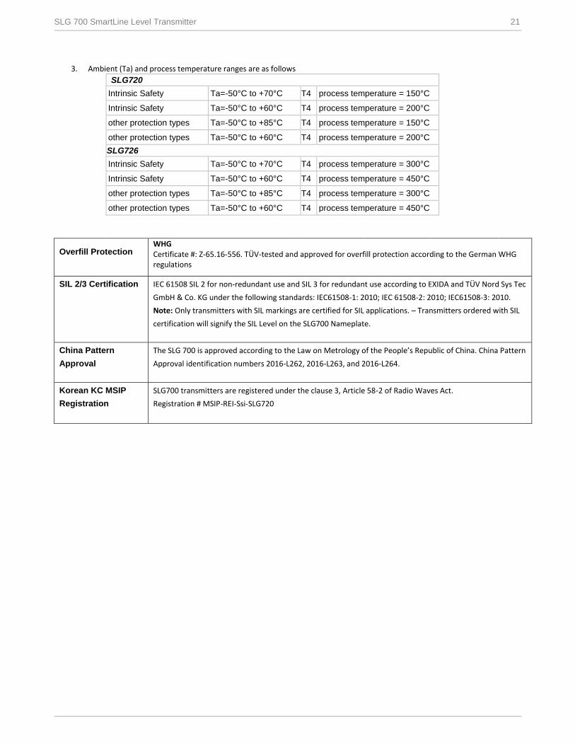
3. Ambient (Ta) and process temperature ranges are as follows
SLG720
Intrinsic Safety Ta=-50°C to +70°C T4 process temperature = 150°C
Intrinsic Safety Ta=-50°C to +60°C T4 process temperature = 200°C
other protection types Ta=-50°C to +85°C T4 process temperature = 150°C
other protection types Ta=-50°C to +60°C T4 process temperature = 200°C
SLG726
Intrinsic Safety Ta=-50°C to +70°C T4 process temperature = 300°C
Intrinsic Safety Ta=-50°C to +60°C T4 process temperature = 450°C
other protection types Ta=-50°C to +85°C T4 process temperature = 300°C
other protection types Ta=-50°C to +60°C T4 process temperature = 450°C
Overfill Protection WHG Certificate #: Z-65.16-556. TÜV-tested and approved for overfill protection according to the German WHG regulations
SIL 2/3 Certification IEC 61508 SIL 2 for non-redundant use and SIL 3 for redundant use according to EXIDA and TÜV Nord Sys Tec
GmbH & Co. KG under the following standards: IEC61508-1: 2010; IEC 61508-2: 2010; IEC61508-3: 2010.
Note: Only transmitters with SIL markings are certified for SIL applications. – Transmitters ordered with SIL
certification will signify the SIL Level on the SLG700 Nameplate.
China Pattern
Approval
The SLG 700 is approved according to the Law on Metrology of the People’s Republic of China. China Pattern
Approval identification numbers 2016-L262, 2016-L263, and 2016-L264.
Korean KC MSIP
Registration
SLG700 transmitters are registered under the clause 3, Article 58-2 of Radio Waves Act.
Registration # MSIP-REI-Ssi-SLG720

22 SLG 700 SmartLine Level Transmitter
Mounting & Dimensional Drawings
Reference Dimensions: millimeters
inches
Figure 20 - SLG720 SmartLine Level with NPT fitting
SLG 700 SmartLine Level Transmitter 23
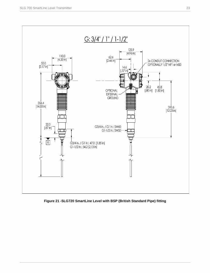
Figure 21 -SLG720 SmartLine Level with BSP (British Standard Pipe) fitting
24 SLG 700 SmartLine Level Transmitter
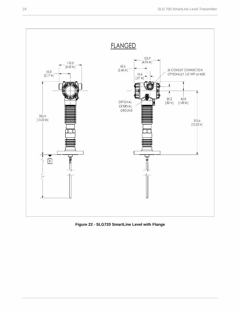
Figure 22 - SLG720 SmartLine Level with Flange

SLG 700 SmartLine Level Transmitter 25
Figure 23 - SmartLine Level with remote housing option (Shown with SLG720)

26 SLG 700 SmartLine Level Transmitter
Figure 24 -SLG720 SmartLine Level rod probes
–
Figure 25 - SLG720 SmartLine Level coaxial probes
SLG 700 SmartLine Level Transmitter 27
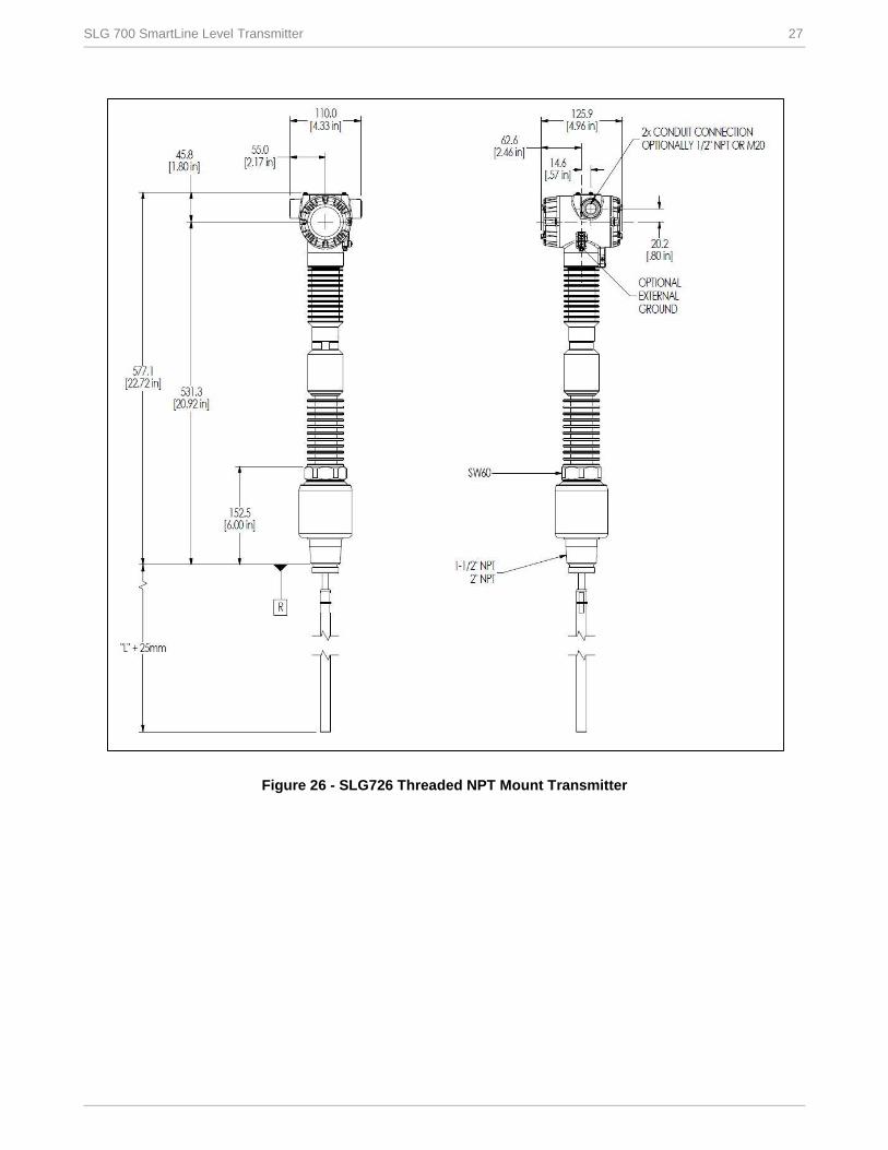
Figure 26 - SLG726 Threaded NPT Mount Transmitter
28 SLG 700 SmartLine Level Transmitter
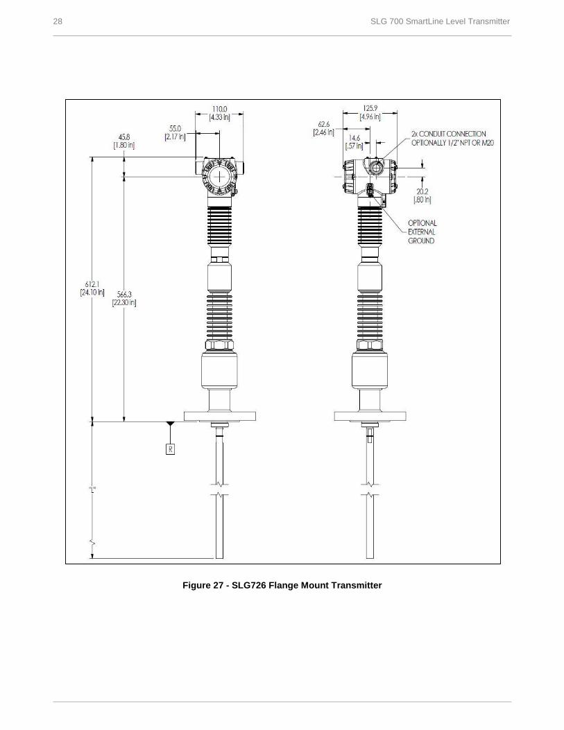
Figure 27 - SLG726 Flange Mount Transmitter
SLG 700 SmartLine Level Transmitter 29
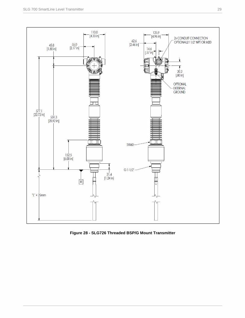
Figure 28 - SLG726 Threaded BSP/G Mount Transmitter
30 SLG 700 SmartLine Level Transmitter
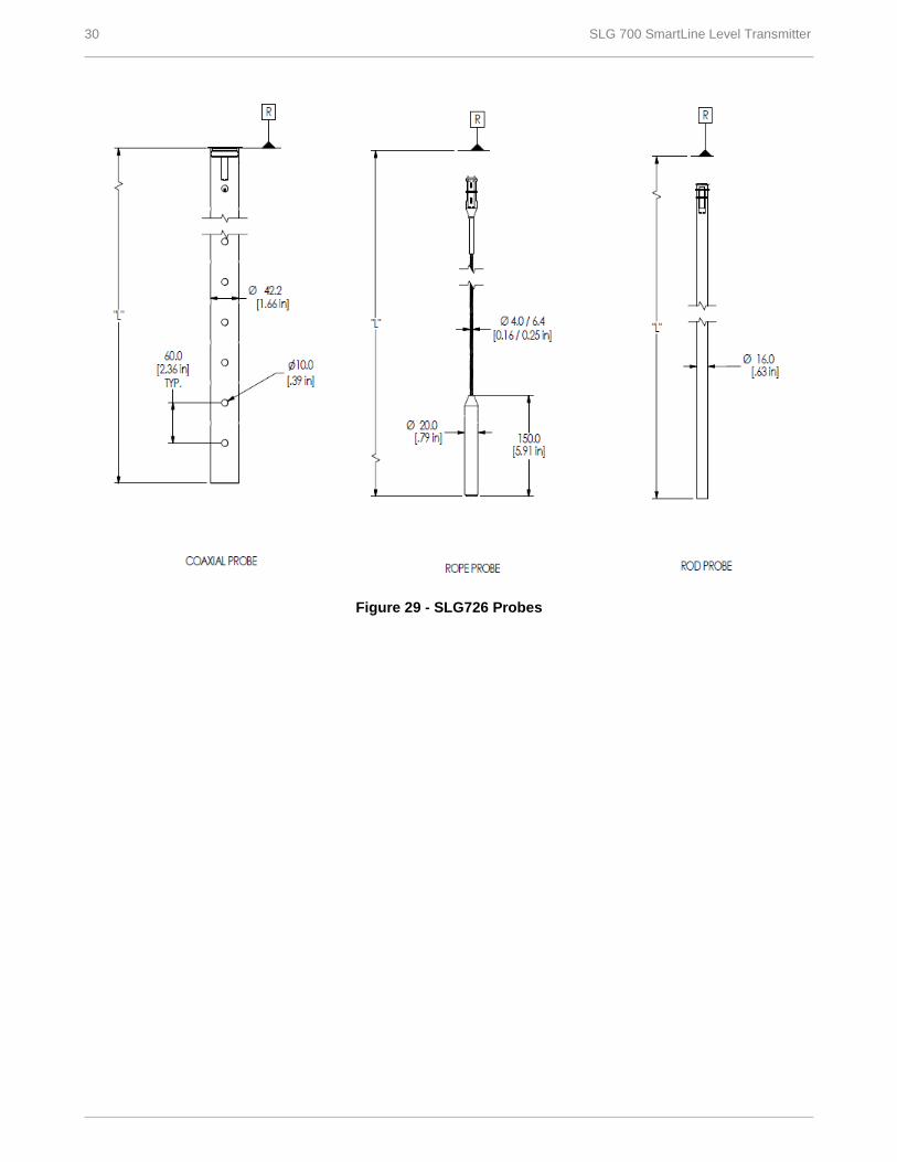
Figure 29 - SLG726 Probes
SLG 700 SmartLine Level Transmitter 31
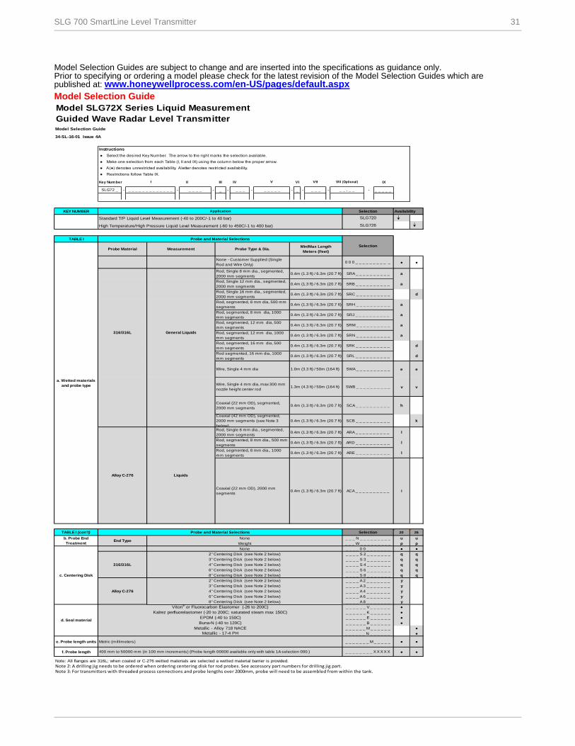
Model Selection Guides are subject to change and are inserted into the specifications as guidance only. Prior to specifying or ordering a model please check for the latest revision of the Model Selection Guides which are published at: www.honeywellprocess.com/en-US/pages/default.aspx
Model Selection Guide
Model SLG72X Series Liquid Measurement
Guided Wave Radar Level TransmitterModel Selection Guide
34-SL-16-01 Issue 4A
Instructions
● Select the desired Key Number. The arrow to the right marks the selection available.
● Make one selection from each Table (I, II and IX) using the column below the proper arrow.
● A (●) denotes unrestricted availability. A letter denotes restricted availability.
● Restrictions follow Table IX.
Key Number II III IV VI IX
- - - _ - - - _ - - - _ _ _ _ _
KEY NUMBER
TABLE I
● ●
a
a
d
a
a
a
a
d
d
e e
v v
h
k
l
l
l
i
TABLE I (con't) 20 26
u u
p p
● ●
q q
q q
q q
q q
q q
y
y
y
y
y
●
●
●
●
●
●
e. Probe length units ● ●
f. Probe length ● ●
Note: All flanges are 316L; when coated or C-276 wetted materials are selected a wetted material barrier is provided.
Note 2: A drilling jig needs to be ordered when ordering centering disk for rod probes. See accessory part numbers for drilling jig part.Note 3: For transmitters with threaded process connections and probe lengths over 2000mm, probe will need to be assembled from within the tank.
_ _ _ _ A 4 _ _ _ _ _ _ _
6" Centering Disk (see Note 2 below) _ _ _ _ A 6 _ _ _ _ _ _ _
316/316L
_ _ _ _ S 2 _ _ _ _ _ _ _
3" Centering Disk (see Note 2 below) _ _ _ _ S 3 _ _ _ _ _ _ _
4" Centering Disk (see Note 2 below) _ _ _ _ S 4 _ _ _ _ _ _ _
6" Centering Disk (see Note 2 below)
2" Centering Disk (see Note 2 below)
_ _ _ _ _ _ M _ _ _ _ _ _
Metallic - 17-4 PH _ _ _ _ _ _ N _ _ _ _ _ _
Metric (millimeters) _ _ _ _ _ _ _ M _ _ _ _ _
400 mm to 50000 mm (in 100 mm increments) (Probe length 00000 available only with table 1A selection 000.) _ _ _ _ _ _ _ _ X X X X X
None _ _ _ _ 0 0 _ _ _ _ _ _ _
_ _ _ _ S 6 _ _ _ _ _ _ _
d. Seal material
Viton® or Fluorocarbon Elastomer (-26 to 200C) _ _ _ _ _ _ V _ _ _ _ _ _
Kalrez perfluorelastomer (-20 to 200C; saturated steam max 150C) _ _ _ _ _ _ K _ _ _ _ _ _
EPDM (-40 to 150C) _ _ _ _ _ _ E _ _ _ _ _ _
Buna-N (-40 to 120C) _ _ _ _ _ _ B _ _ _ _ _ _
Metallic - Alloy 718 NACE
8" Centering Disk (see Note 2 below) _ _ _ _ A 8 _ _ _ _ _ _ _
8" Centering Disk (see Note 2 below) _ _ _ _ S 8 _ _ _ _ _ _ _c. Centering Disk
Alloy C-276
2" Centering Disk (see Note 2 below) _ _ _ _ A 2 _ _ _ _ _ _ _
3" Centering Disk (see Note 2 below) _ _ _ _ A 3 _ _ _ _ _ _ _
4" Centering Disk (see Note 2 below)
ARD _ _ _ _ _ _ _ _ _ _
b. Probe End
TreatmentEnd Type
None _ _ _ N _ _ _ _ _ _ _ _ _
Weight _ _ _ W _ _ _ _ _ _ _ _ _
Alloy C-276 Liquids
Rod, Single 8 mm dia., segmented,
2000 mm segments0.4m (1.3 ft) / 6.3m (20.7 ft) ARA _ _ _ _ _ _ _ _ _ _
Rod, segmented, 8 mm dia., 1000
mm segments
Coaxial (22 mm OD), 2000 mm
segments 0.4m (1.3 ft) / 6.3m (20.7 ft) ACA _ _ _ _ _ _ _ _ _ _
0.4m (1.3 ft) / 6.3m (20.7 ft)
SRN _ _ _ _ _ _ _ _ _ _
Rod, segmented, 16 mm dia, 500
mm segments
Coaxial (22 mm OD), segmented,
2000 mm segments0.4m (1.3 ft) / 6.3m (20.7 ft) SCA _ _ _ _ _ _ _ _ _ _
0.4m (1.3 ft) / 6.3m (20.7 ft) SRK _ _ _ _ _ _ _ _ _ _
Rod segmented, 16 mm dia, 1000
mm segments0.4m (1.3 ft) / 6.3m (20.7 ft)
0.4m (1.3 ft) / 6.3m (20.7 ft) SRH _ _ _ _ _ _ _ _ _ _
SWB _ _ _ _ _ _ _ _ _ _
0.4m (1.3 ft) / 6.3m (20.7 ft) ARE _ _ _ _ _ _ _ _ _ _
Rod, segmented, 8 mm dia., 500 mm
segments0.4m (1.3 ft) / 6.3m (20.7 ft)
Probe Material Measurement Probe Type & Dia.Min/Max Length
Meters (Feet)
None - Customer Supplied (Single
Rod and Wire Only)
Wire, Single 4 mm dia 1.0m (3.3 ft) / 50m (164 ft)
0.4m (1.3 ft) / 6.3m (20.7 ft)
0 0 0 _ _ _ _ _ _ _ _ _ _
Rod, Single 8 mm dia., segmented,
2000 mm segments
Coaxial (42 mm OD), segmented,
2000 mm segments (see Note 3
below)
0.4m (1.3 ft) / 6.3m (20.7 ft) SCB _ _ _ _ _ _ _ _ _ _
SWA _ _ _ _ _ _ _ _ _ _
Availability
VIII (Optional)
SelectionProbe and Material Selections
_ _ , _ _
SRL _ _ _ _ _ _ _ _ _ _
0.4m (1.3 ft) / 6.3m (20.7 ft) SRM _ _ _ _ _ _ _ _ _ _
Rod, segmented, 12 mm dia, 1000
mm segments
Rod, Single 16 mm dia., segmented,
2000 mm segments
I V VII
Application Selection
Rod, Single 12 mm dia., segmented,
2000 mm segments0.4m (1.3 ft) / 6.3m (20.7 ft) SRB _ _ _ _ _ _ _ _ _ _
High Temperature/High Pressure Liquid Level Measurement (-60 to 450C/-1 to 400 bar) SLG726
Standard T/P Liquid Level Measurement (-40 to 200C/-1 to 40 bar) SLG720
SLG72 _ _ _ _ _ _ _ _ _ _ _ _ _ _ _ _ _ _ _ _ _ _ _ _ _ _ _ _ _
Probe and Material Selections
Selection
316/316L General Liquids
0.4m (1.3 ft) / 6.3m (20.7 ft) SRA _ _ _ _ _ _ _ _ _ _
Rod, segmented, 8 mm dia, 1000
mm segments0.4m (1.3 ft) / 6.3m (20.7 ft) SRJ _ _ _ _ _ _ _ _ _ _
Rod, segmented, 12 mm dia, 500
mm segments
SRC _ _ _ _ _ _ _ _ _ _
Rod, segmented, 8 mm dia, 500 mm
segments
Wire, Single 4 mm dia, max 300 mm
nozzle height center rod1.3m (4.3 ft) / 50m (164 ft)
a. Wetted materials
and probe type
32 SLG 700 SmartLine Level Transmitter
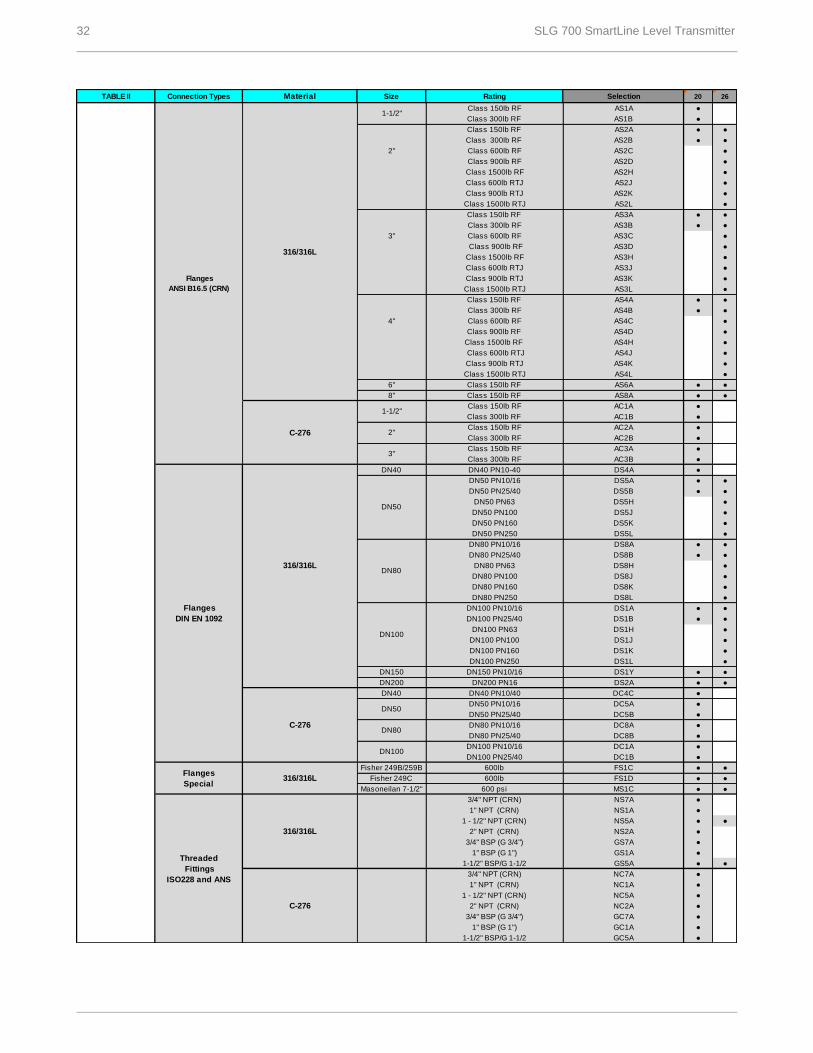
TABLE II 20 26
●
●
● ●
● ●
●
●
●
●
●
●
● ●
● ●
●
●
●
●
●
●
● ●
● ●
●
●
●
●
●
●
● ●
● ●
●
●
●
●
●
●
●
● ●
● ●
●
●
●
●
● ●
● ●
●
●
●
●
● ●
● ●
●
●
●
●
● ●
● ●
●
●
●
●
●
●
●
● ●
● ●
● ●
●
●
● ●
●
●
●
● ●
●
●
●
●
●
●
●
NC7A
NC1A
NC5A
NC2A
GC7A
GC1A
GC5A
Threaded
Fittings
ISO228 and ANS
C-276
3/4" NPT (CRN)
1" NPT (CRN)
1 - 1/2" NPT (CRN)
2" NPT (CRN)
3/4" BSP (G 3/4")
1" BSP (G 1")
1-1/2" BSP/G 1-1/2
316/316L
GS7A
NS1A
1 - 1/2" NPT (CRN) NS5A
2" NPT (CRN) NS2A
3/4" NPT (CRN) NS7A
1" NPT (CRN)
3/4" BSP (G 3/4")
1" BSP (G 1") GS1A
1-1/2" BSP/G 1-1/2 GS5A
Flanges
Special316/316L
Fisher 249B/259B 600lb FS1C
Fisher 249C 600lb FS1D
Masoneilan 7-1/2" 600 psi MS1C
C-276
DN50 PN25/40
DN40 DN40 PN10/40 DC4C
DN50DN50 PN10/16 DC5A
DC5B
DN80DN80 PN10/16 DC8A
DN80 PN25/40 DC8B
DN100DN100 PN10/16 DC1A
DN100 PN25/40 DC1B
DS1H
DN100 PN100 DS1J
DN100 PN160 DS1K
Flanges
DIN EN 1092
316/316L
DN40 DN40 PN10-40 DS4A
DN200 DN200 PN16 DS2A
DN100 PN250 DS1L
DN150 DN150 PN10/16 DS1Y
DN50 PN250 DS5L
DN80
DN80 PN10/16 DS8A
DN80 PN25/40 DS8B
DN80 PN63 DS8H
DN80 PN100
DN50
DN50 PN10/16 DS5A
DN50 PN25/40 DS5B
DN100 PN63
DS8J
DN80 PN160 DS8K
DN80 PN250 DS8L
DS5K
C-276
1-1/2" Class 150lb RF AC1A
Class 300lb RF AC1B
2" Class 150lb RF AC2A
Class 300lb RF AC2B
3" Class 150lb RF AC3A
Class 300lb RF AC3B
DN100
Class 150lb RF AS6A
8" Class 150lb RF AS8A
Class 1500lb RTJ AS3L
4"
Class 150lb RF
DN50 PN63 DS5H
DN50 PN100 DS5J
DN100 PN10/16 DS1A
DN100 PN25/40 DS1B
AS4H
AS4L
AS4A
Class 300lb RF AS4B
Class 600lb RF AS4C
Class 900lb RF AS4D
Class 1500lb RF
Class 600lb RTJ AS4J
Class 900lb RTJ
DN50 PN160
Material Size Rating Selection
AS2A
3"
Class 150lb RF
AS4K
AS3D
Class 1500lb RTJ AS2L
6"
Class 1500lb RTJ
AS3A
Class 300lb RF AS3B
Class 600lb RF AS3C
Class 900lb RF
Class 1500lb RF
Class 600lb RF AS2C
Class 900lb RF AS2D
Class 1500lb RF AS3H
Class 600lb RTJ AS3J
Class 900lb RTJ AS3K
AS2H
Class 600lb RTJ AS2J
Class 900lb RTJ AS2K
Flanges
ANSI B16.5 (CRN)
316/316L
1-1/2" Class 150lb RF AS1A
Class 300lb RF
Class 300lb RF AS2B
AS1B
2"
Class 150lb RF
Connection Types
SLG 700 SmartLine Level Transmitter 33
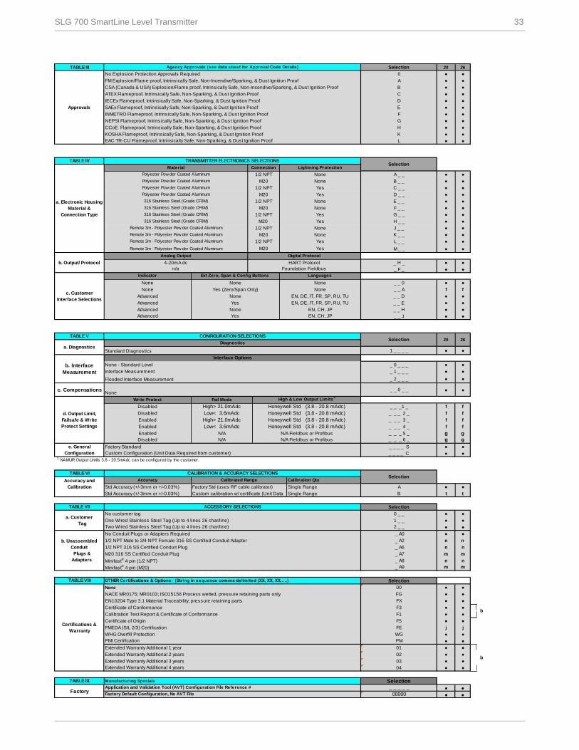
TABLE III 20 26
● ●
● ●
● ●
● ●
● ●
● ●
● ●
● ●
● ●
● ●
● ●
TABLE IV
● ●
● ●
● ●
● ●
● ●
● ●
● ●
● ●
● ●
● ●
● ●
● ●
● ●
● ●
● ●
f f
● ●
● ●
● ●
● ●
TABLE V
● ●
● ●
● ●
● ●
● ●
f f
f f
f f
f f
g g
g g
● ●
● ● 3 NAMUR Output Limits 3.8 - 20.5mAdc can be configured by the customer.
TABLE VI
Calibration Qty
● ●
t t
TABLE VII
● ●
● ●
● ●
● ●
n n
n n
m m
n n
m m
TABLE VIII
● ●
● ●
● ●
● ●
● ●
● ●
j j
● ●
PMI Certification ● ●
● ●
● ●
● ●
● ●
TABLE IX
● ●
● ●
Agency Approvals (see data sheet for Approval Code Details) Selection
D
SAEx Flameproof, Intrinsically Safe, Non-Sparking, & Dust Ignition Proof E
INMETRO Flameproof, Intrinsically Safe, Non-Sparking, & Dust Ignition Proof F
Approvals
No Explosion Protection Approvals Required 0
FM Explosion/Flame proof, Intrinsically Safe, Non-Incendive/Sparking, & Dust Ignition Proof A
CSA (Canada & USA) Explosion/Flame proof, Intrinsically Safe, Non-Incendive/Sparking, & Dust Ignition Proof B
ATEX Flameproof, Intrinsically Safe, Non-Sparking, & Dust Ignition Proof C
IECEx Flameproof, Intrinsically Safe, Non-Sparking, & Dust Ignition Proof
a. Electronic Housing
Material &
Connection Type
Material Connection Lightning Protection
Polyester Pow der Coated Aluminum 1/2 NPT None A _ _
TRANSMITTER ELECTRONICS SELECTIONSSelection
NEPSI Flameproof, Intrinsically Safe, Non-Sparking, & Dust Ignition Proof G
CCoE Flameproof, Intrinsically Safe, Non-Sparking, & Dust Ignition Proof H
K
EAC TR-CU Flameproof, Intrinsically Safe, Non-Sparking, & Dust Ignition Proof L
316 Stainless Steel (Grade CF8M) M20 None F _ _
316 Stainless Steel (Grade CF8M) 1/2 NPT Yes G _ _
Polyester Pow der Coated Aluminum M20 Yes D _ _
316 Stainless Steel (Grade CF8M) 1/2 NPT None E _ _
Polyester Pow der Coated Aluminum M20 None B _ _
Polyester Pow der Coated Aluminum 1/2 NPT Yes C _ _
Remote 3m - Polyester Pow der Coated Aluminum M20 Yes M _ _
Remote 3m - Polyester Pow der Coated Aluminum M20 None K _ _
Remote 3m - Polyester Pow der Coated Aluminum 1/2 NPT Yes L _ _
316 Stainless Steel (Grade CF8M) M20 Yes H _ _
Remote 3m - Polyester Pow der Coated Aluminum 1/2 NPT None J _ _
4-20mA dc HART Protocol _ H _
n/a Foundation Fieldbus _ F _
Analog Output Digital Protocol
c. Customer
Interface Selections
Indicator Ext Zero, Span & Config Buttons Languages
None None None
b. Output/ Protocol
Advanced Yes EN, DE, IT, FR, SP, RU, TU _ _ E
_ _ 0
a. DiagnosticsDiagnostics
Standard Diagnostics 1 _ _ _ _
CONFIGURATION SELECTIONSSelection 20
None Yes (Zero/Span Only) None _ _ A
Advanced None EN, DE, IT, FR, SP, RU, TU _ _ D
Advanced None EN, CH, JP _ _ H
Advanced Yes EN, CH, JP _ _ J
26
d. Output Limit,
Failsafe & Write
Protect Settings
Write Protect Fail Mode High & Low Output Limits3
Disabled High> 21.0mAdc Honeywell Std (3.8 - 20.8 mAdc)
Disabled N/A N/A Fieldbus or Profibus _ _ _ 6 _
_ 2 _ _ _
c. CompensationsNone
_ _ 0 _ _
b. Interface
Measurement
Interface Options
None - Standard Level _ 0 _ _ _
Interface Measurement _ 1 _ _ _
Flooded Interface Measurement
Accuracy Calibrated Range
Std Accuracy (+/-3mm or +/-0.03%) Factory Std (uses RF cable calibrator) Single Range A
Std Accuracy (+/-3mm or +/-0.03%)
_ _ _1 _
Disabled Low< 3.6mAdc Honeywell Std (3.8 - 20.8 mAdc) _ _ _ 2 _
Enabled High> 21.0mAdc Honeywell Std (3.8 - 20.8 mAdc) _ _ _ 3 _
ACCESSORY SELECTIONS Selection
a. Customer
Tag
No customer tag 0 _ _
One Wired Stainless Steel Tag (Up to 4 lines 26 char/line) 1 _ _
Two Wired Stainless Steel Tag (Up to 4 lines 26 char/line) 2 _ _
e. General
Configuration
Factory Standard _ _ _ _ S
Custom Configuration (Unit Data Required from customer) _ _ _ _ C
Enabled Low< 3.6mAdc Honeywell Std (3.8 - 20.8 mAdc) _ _ _ 4 _
Enabled N/A N/A Fieldbus or Profibus _ _ _ 5 _
Custom calibration w/ certificate (Unit Data Single Range B
CALIBRATION & ACCURACY SELECTIONSSelection
Accuracy and
Calibration
FX
Certificate of Conformance F3
_ A8
Minifast® 4 pin (M20) _ A9
OTHER Certifications & Options: (String in sequence comma delimited (XX, XX, XX,….) Selection
None 00
NACE MR0175; MR0103; ISO15156 Process wetted, pressure retaining parts only FG
b. Unassembled
Conduit
Plugs &
Adapters
No Conduit Plugs or Adapters Required _ A0
1/2 NPT Male to 3/4 NPT Female 316 SS Certified Conduit Adapter _ A2
1/2 NPT 316 SS Certified Conduit Plug _ A6
M20 316 SS Certified Conduit Plug _ A7
Minifast® 4 pin (1/2 NPT)
Manufacturing Specials Selection
FactoryApplication and Validation Tool (AVT) Configuration File Reference # _ _ _ _ _
Factory Default Configuration, No AVT File 00000
bExtended Warranty Additional 2 years 02
Extended Warranty Additional 3 years 03
Extended Warranty Additional 4 years 04
FMEDA (SIL 2/3) Certification FE
WHG Overfill Protection WG
PM
Extended Warranty Additional 1 year 01
Certifications &
Warranty
bCalibration Test Report & Certificate of Conformance F1
Certificate of Origin F5
EN10204 Type 3.1 Material Traceability; pressure retaining parts
KOSHA Flameproof, Intrinsically Safe, Non-Sparking, & Dust Ignition Proof
34 SLG 700 SmartLine Level Transmitter
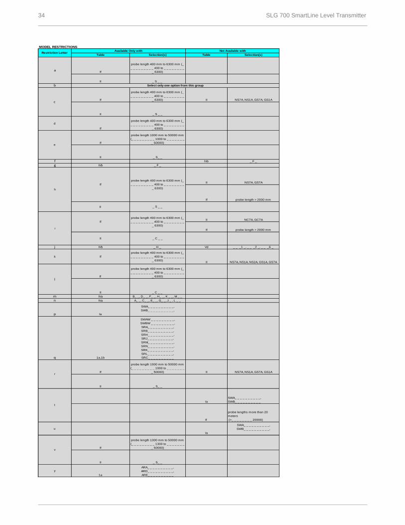
MODEL RESTRICTIONS
b
d
fg
II
j
k
If
mn
p
q
u
y
1a
ARA_ _ _ _ _ _ _ _ _ _,
ARD_ _ _ _ _ _ _ _ _ _,
ARE_ _ _ _ _ _ _ _ _ _
If
probe length 1300 mm to 50000 mm
(_ _ _ _ _ _ _ _ _ 1300 to _ _ _ _ _ _ _
_ 50000)
Ia
SWA_ _ _ _ _ _ _ _ _ _,
SWB_ _ _ _ _ _ _ _ _ _,
Ia
SWA_ _ _ _ _ _ _ _ _ _,
SWB_ _ _ _ _ _ _ _ _ _,
1a,1b
IVb _ F _
tIa
SWA_ _ _ _ _ _ _ _ _ _,
SWB_ _ _ _ _ _ _ _ _ _
If
probe lengths more than 20
meters
(>_ _ _ _ _ _ _ _ 20000)
Vd _ _ _1 _, _ _ _2 _, _ _ _6 _
If
probe length 400 mm to 6300 mm (_
_ _ _ _ _ _ _ _ _ 400 to _ _ _ _ _ _ _ _
_ 6300)II NS7A, NS1A, NS2A, GS1A, GS7A
probe length 1000 mm to 50000 mm
(_ _ _ _ _ _ _ _ _ 1000 to _ _ _ _ _ _ _
_ 50000) II NS7A, NS1A, GS7A, GS1A
SWAW _ _ _ _ _ _ _ _ _,
SWBW _ _ _ _ _ _ _ _ _,
SRA_ _ _ _ _ _ _ _ _ _,
SRB_ _ _ _ _ _ _ _ _ _,
SRH_ _ _ _ _ _ _ _ _ _,
SRJ_ _ _ _ _ _ _ _ _ _,
SRM_ _ _ _ _ _ _ _ _ _,
SRN_ _ _ _ _ _ _ _ _ _,
SRK_ _ _ _ _ _ _ _ _ _,
SRL_ _ _ _ _ _ _ _ _ _,
SRC_ _ _ _ _ _ _ _ _ _
If
IVa B_ _, D_ _, F_ _, H_ _, K _ _, M _ _
IVa A_ _, C_ _, E_ _, G_ _, J _ , L _ _
Restriction LetterAvailable Only with Not Available with
Table Selection(s) Table Selection(s)
Select only one option from this group
If
probe length 400 mm to 6300 mm (_
_ _ _ _ _ _ _ _ _ 400 to _ _ _ _ _ _ _ _
_ 6300) II NS7A, NS1A, GS7A, GS1A
If
probe length 400 mm to 6300 mm (_
_ _ _ _ _ _ _ _ _ 400 to _ _ _ _ _ _ _ _
_ 6300)
c
II _ S _ _
aIf
probe length 400 mm to 6300 mm (_
_ _ _ _ _ _ _ _ _ 400 to _ _ _ _ _ _ _ _
_ 6300)
If
probe length 1000 mm to 50000 mm
(_ _ _ _ _ _ _ _ _ 1000 to _ _ _ _ _ _ _
_ 50000)
h
_ S _ _
i
If
II
probe length 400 mm to 6300 mm (_
_ _ _ _ _ _ _ _ _ 400 to _ _ _ _ _ _ _ _
_ 6300)
II
If
NC7A, GC7A
probe length > 2000 mm
_ C _ _
l
probe length 400 mm to 6300 mm (_
_ _ _ _ _ _ _ _ _ 400 to _ _ _ _ _ _ _ _
_ 6300)
_ C _ _ II
If
probe length 400 mm to 6300 mm (_
_ _ _ _ _ _ _ _ _ 400 to _ _ _ _ _ _ _ _
_ 6300)
II NS7A, GS7A
If probe length > 2000 mm
IVb _ F _
IVb _ H _
II _ S _ _
II _ S_ _
e
v
II _ S_ _
II _ S_ _
r
SLG 700 SmartLine Level Transmitter 35
HART® is a registered trademark of HART Communication Foundation.
FOUNDATIONTM Fieldbus is a trademark of Fieldbus Foundation.
Viton® is a registered trademark of DuPont Performance Elastomers.
Teflon® is a registered trademark of DuPont.
FM ApprovalsSM is a service mark of FM Global
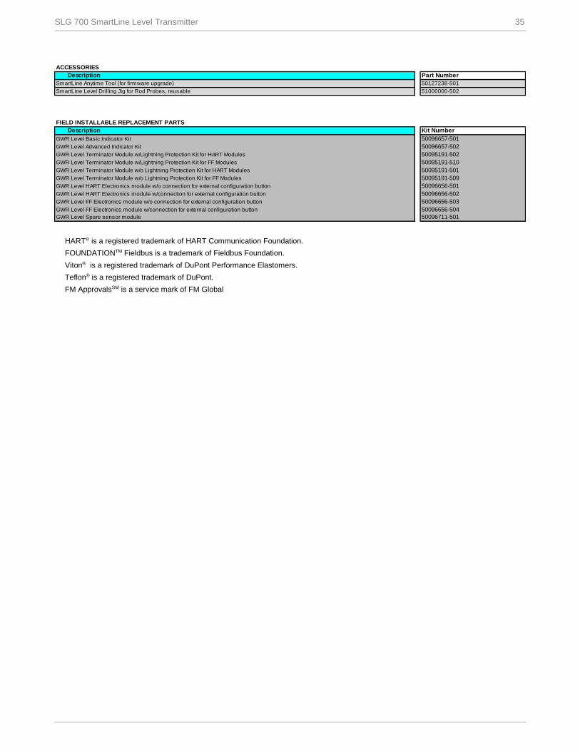
ACCESSORIES
Description Part Number
SmartLine Level Drilling Jig for Rod Probes, reusable
FIELD INSTALLABLE REPLACEMENT PARTS
Description
GWR Level Basic Indicator Kit
GWR Level Advanced Indicator Kit
GWR Level Terminator Module w/Lightning Protection Kit for HART Modules
GWR Level Terminator Module w/Lightning Protection Kit for FF Modules
GWR Level Terminator Module w/o Lightning Protection Kit for HART Modules
GWR Level Terminator Module w/o Lightning Protection Kit for FF Modules
GWR Level HART Electronics module w/o connection for external configuration button
GWR Level HART Electronics module w/connection for external configuration button
GWR Level FF Electronics module w/o connection for external configuration button
GWR Level FF Electronics module w/connection for external configuration button 50096656-504
GWR Level Spare sensor module
50096656-503
50096711-501
50095191-502
50095191-510
50095191-501
50095191-509
50096656-501
50096656-502
SmartLine Anytime Tool (for firmware upgrade) 50127238-501
51000000-502
Kit Number
50096657-501
50096657-502
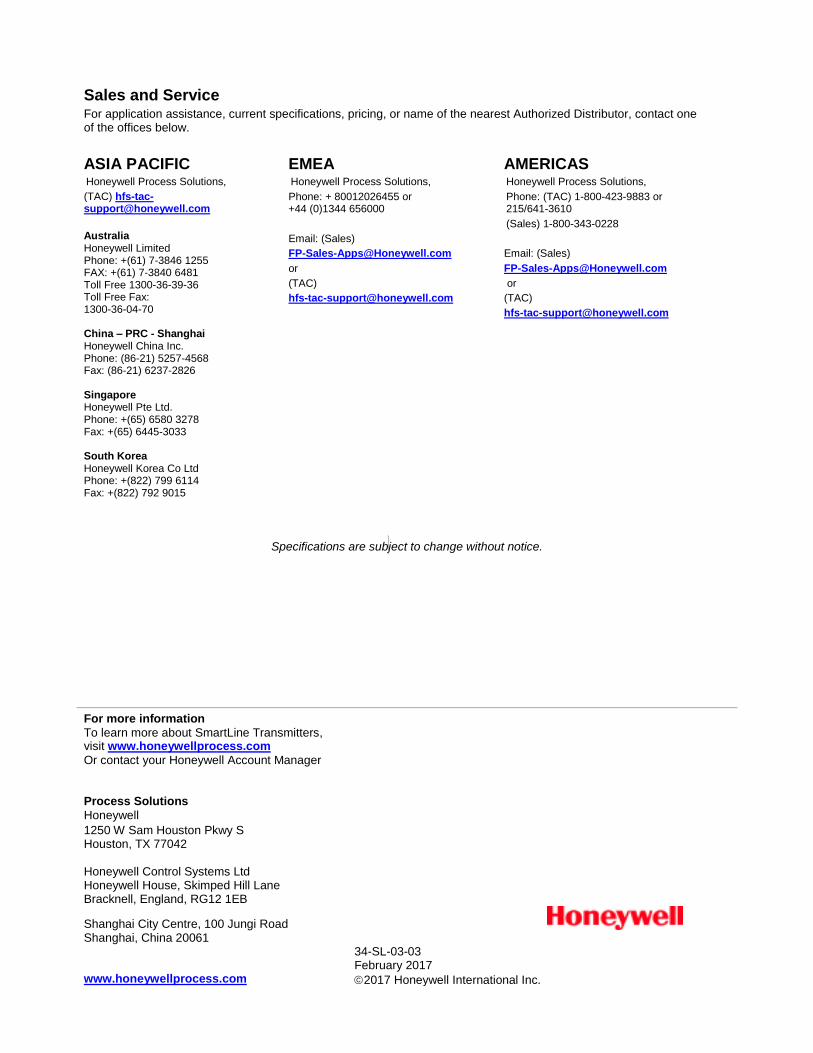
For more information
To learn more about SmartLine Transmitters, visit www.honeywellprocess.com
Or contact your Honeywell Account Manager
Process Solutions
Honeywell
1250 W Sam Houston Pkwy S Houston, TX 77042
Honeywell Control Systems Ltd Honeywell House, Skimped Hill Lane Bracknell, England, RG12 1EB
34-SL-03-03 February 2017
2017 Honeywell International Inc.
Shanghai City Centre, 100 Jungi Road Shanghai, China 20061 www.honeywellprocess.com
Sales and Service For application assistance, current specifications, pricing, or name of the nearest Authorized Distributor, contact one of the offices below.
ASIA PACIFIC Honeywell Process Solutions,
(TAC) [email protected]
Australia Honeywell Limited Phone: +(61) 7-3846 1255 FAX: +(61) 7-3840 6481 Toll Free 1300-36-39-36 Toll Free Fax: 1300-36-04-70 China – PRC - Shanghai Honeywell China Inc. Phone: (86-21) 5257-4568 Fax: (86-21) 6237-2826
Singapore Honeywell Pte Ltd. Phone: +(65) 6580 3278 Fax: +(65) 6445-3033 South Korea Honeywell Korea Co Ltd Phone: +(822) 799 6114 Fax: +(822) 792 9015
EMEA Honeywell Process Solutions,
Phone: + 80012026455 or +44 (0)1344 656000
Email: (Sales)
or
(TAC)
AMERICAS Honeywell Process Solutions,
Phone: (TAC) 1-800-423-9883 or 215/641-3610
(Sales) 1-800-343-0228
Email: (Sales)
or
(TAC)
Specifications are subject to change without notice.