Embed Size (px)
Citation preview

HONG KONG CIVIL AVIATION DEPARTMENT
CAD 453(A)
FLIGHT SIMULATOR QUALIFICATIONS (AEROPLANE)
FSQ (A) 2nd Edition April 2021


Flight Simulator Qualifications (Aeroplane) CAD 453(A)
April 2021 Page i
CHECKLIST OF PAGES Page No Date Page No Date Page No Date
i April 2021 CHAPTER 4 APPENDIX 1 71 April 2021
ii April 2021 30 April 2021 72 April 2021
iii April 2021 CHAPTER 4 APPENDIX 2 73 April 2021
iv April 2021 31 April 2021 74 April 2021
v April 2021 32 April 2021 75 April 2021
vi April 2021 33 April 2021 76 April 2021
34 April 2021 77 April 2021
CHAPTER 1 35 April 2021 78 April 2021
1 April 2021 36 April 2021 79 April 2021
2 April 2021 37 April 2021 80 April 2021
3 April 2021 38 April 2021 81 April 2021
4 April 2021 39 April 2021 82 April 2021
5 April 2021 40 April 2021 CHAPTER 5 APPENDIX 2
6 April 2021 41 April 2021 83 April 2021
7 April 2021 42 April 2021 84 April 2021
8 April 2021 43 April 2021 85 April 2021
9 April 2021 44 April 2021 86 April 2021
45 April 2021 87 April 2021
CHAPTER 2 46 April 2021 CHAPTER 5 APPENDIX 3
10 April 2021 88 April 2021
11 April 2021 CHAPTER 5 CHAPTER 5 APPENDIX 4
12 April 2021 47 April 2021 89 April 2021
13 April 2021 48 April 2021
14 April 2021 49 April 2021 CHAPTER 6
CHAPTER 2 APPENDIX 1 CHAPTER 5 APPENDIX 1 90 April 2021
15 April 2021 50 April 2021 91 April 2021
16 April 2021 51 April 2021 CHAPTER 6 APPENDIX 1
17 April 2021 52 April 2021 92 April 2021
CHAPTER 2 APPENDIX 2 53 April 2021 93 April 2021
18 April 2021 54 April 2021 94 April 2021
19 April 2021 55 April 2021 95 April 2021
20 April 2021 56 April 2021 96 April 2021
57 April 2021 97 April 2021
CHAPTER 3 58 April 2021 98 April 2021 21 April 2021 59 April 2021 99 April 2021 22 April 2021 60 April 2021 100 April 2021 23 April 2021 61 April 2021 101 April 2021 CHAPTER 3 APPENDIX 1 62 April 2021 102 April 2021 24 April 2021 63 April 2021 103 April 2021 64 April 2021 104 April 2021 CHAPTER 4 65 April 2021 105 April 2021
25 April 2021 66 April 2021 106 April 2021
26 April 2021 67 April 2021
27 April 2021 68 April 2021 CHAPTER 7
28 April 2021 69 April 2021 107 April 2021
29 April 2021 70 April 2021 108 April 2021

Flight Simulator Qualifications (Aeroplane) CAD 453(A)
April 2021 Page ii
CHECKLIST OF PAGES Page No Date
109 April 2021 CHAPTER 8 110 April 2021 111 April 2021 CHAPTER 9 112 April 2021
113 April 2021 114 April 2021 CHAPTER 10 115 April 2021 116 April 2021 117 April 2021 118 April 2021 119 April 2021 120 April 2021 121 April 2021 122 April 2021 123 April 2021 121 April 2021
122 April 2021
123 April 2021
APPENDUM
124 April 2021

Flight Simulator Qualifications (Aeroplane) CAD 453(A)
April 2021 Page iii
RECORD OF AMENDMENTS
Amendment No. Date of Issue Amended by
2nd Edition Issue 1 14 April 2021 ***

Flight Simulator Qualifications (Aeroplane) CAD 453(A)
April 2021 Page iv
INTENTIONALLY LEFT BLANK

Flight Simulator Qualifications (Aeroplane) CAD 453(A)
April 2021 Page v
FOREWORD I. Flight Simulation Training Devices (FSTDs) utilised by Hong Kong flight crew licence
holders within Hong Kong SAR or overseas, must be approved or accepted by the Hong Kong Civil Aviation Department (CAD) to the operational standards and requirements listed in this publication before credits, training and/or testing conducted utilising such FSTDs will be recognised by CAD.
II. CAD, may grant approval for FSTD credits as a result of compliance with this publication and the degree of realism found to exist. The approval/acceptance will also be dependent upon the applicant's training and checking organisation being approved to conduct training and checking in the nominated FSTDs.
III. No approved training sequence in a FSTD can be used as a credit towards a flight crew flight proficiency test or experience credit until such time as the FSTD has satisfactorily completed an accreditation check by a suitably qualified inspector of CAD to ensure suitability for intended use.
IV. An accreditation check must be performed by CAD, prior to CAD assigning the FSTD a level of accreditation. It is a requirement that approved FSTDs maintain the performance, functional and other characteristics that were required for the accreditation. Ongoing approval of the FSTD is conditional upon recurrent checks demonstrating the continued fidelity of the FSTD at regular intervals after initial accreditation.
V. Various Acceptable Means of Compliance (AMCs) are presented by the worldwide authorities oversighting FSTD use and accreditation, (eg ICAO 9625 – Manual of Criteria for the qualification of FSTD’s/EASA CS-FSTD(A) issue 2, 3 May,2018/FAA Part 60). These various AMC standards may be used as applicable. Final assessment/approval for the particular FSTD use will only be given by CAD.
VI. The policy concerning the accreditation and fidelity checking of overseas flight simulators is the same as the requirements for FSTDs located in the Hong Kong SAR.
VII. It is to be noted that this Document is a complete reissue of the previous CAD 453(A) and (H), updating it to current standards. Therefore no vertical amendment highlight bars are to be found.
Note: Most FSTDs within Hong Kong SAR, if not all, are in the Full Flight Simulator category. For clarity, FSTD official documents may be referred to as ‘FLIGHT SIMULATOR APPROVAL’ .

Flight Simulator Qualifications (Aeroplane) CAD 453(A)
April 2021 Page vi
CONTENTS
Page FOREWORD v CONTENTS vi CHAPTERS 1 INTRODUCTION 1 2 REQUIREMENTS FOR AEROPLANE SIMULATORS 10 3 FLIGHT SIMULATOR TRAINING DEVICE EVALUATIONS 21 4 TESTING FOR SIMULATOR QUALIFICATION 25 5 SIMULATOR VALIDATION TESTS 47 6 FUNCTIONS AND SUBJECTIVE TESTS 90 7 LEVEL 'A' FLIGHT SIMULATORS 107 8 FLIGHT SIMULATOR TRAINING DEVICES APPROVED OR QUALIFIED UNDER
PREVIOUS REGULATIONS 110 9 NEW AIRCRAFT PROGRAMMES 112 10 QUALITY SYSTEM 115 APPENDUM – Suggested Reference Sources for CAD 453(A) 124

Flight Simulator Qualifications (Aeroplane) CAD 453(A)
April 2021 Page 1
CHAPTER 1 INTRODUCTION 1. Purpose
1.1 The Air Navigation (Hong Kong) Order 1995 (the Order) provides for the use of flight
simulators approved by CAD for some of the training and tests of competency called for under the provisions of the Order. The purpose of this document is to establish the standards which define the performance and documentation requirements for the evaluation of aeroplane Flight Simulator Training Devices (FSTDs) used for training of flight crew members, and for the conduct of flying tests called for in Schedule 9 & 11 to the Order.
2. Background
2.1 The availability of advanced technology has permitted greater use of FSTDs for training
and checking of flight crew members. The complexity, costs and operating environment of modern aeroplanes also have encouraged broader use of advanced simulation. FSTDs can provide more in-depth training than can be accomplished in aeroplanes and provide a safe and suitable learning environment. Fidelity of modern simulators is sufficient to permit pilot assessment with assurance that the observed behavior will transfer to the aeroplane. Fuel conservation and reduction in adverse environmental effects are important by-products of flight simulator use.
3. Applicability
3.1 Pursuant to Schedule 9 and Schedule 11 to the Air Navigation (Hong Kong) Order 1995
(Cap. 448C), the use of flight simulators (or FSTDs) for the purpose of tests shall be approved by CAD. CAD 453(A) shall apply to FSTD operators seeking for qualification of any FSTD for the aforementioned purpose. The FSTD may be used only under the supervision of an appointed competent person approved for the same purpose. While this document provides some general guidance material for FSTD users, it should be again noted that there are various oversighting agencies suppling Acceptable Means of Compliance (AMC) information (e.g. ICAO, EASA, FAA etc.), which may be consulted during the application or renewal process. Final acceptance of any utilized AMC guidance remains with CAD. Furthermore, for clarity, precise details of any credit/training/test approvals are contained in the ‘Schedule’ to the FSTD Approval Document issued by CAD.
4. Paragraph Numbering
4.1 A non-standard paragraph numbering system has been adopted in some of the Appendices to
facilitate tabularization.
5. Amendments
5.1 Amendments to this document will be forwarded to all operators of FSTD approved under these arrangements. Additional copies of the document, and amendments, are available from CAD.
6. Terminology
6.1 Because of the technical complexity of FSTDs qualification, it is essential that standard terminology is used throughout. The following principal terms and abbreviations must be used in order to comply with CAD 453(A): Flight Simulation Training Device (FSTD). A training device which is: In the case of aeroplanes, a Full Flight Simulator (FFS), a Flight Training Device (FTD), a Flight
Flight Simulator Qualifications (Aeroplane) CAD 453(A)
April 2021 Page 2
Navigation Procedures Trainer (FNPT), or a Basic Instrument Training Device (BITD). In the case of helicopters, a Full Flight Simulator (FFS), a Flight Training Device (FTD) or a Flight Navigation Procedures Trainer (FNPT). Full Flight Simulator (FFS). A full size replica of a specific type or make, model and series aeroplane flight deck/cockpit, including the assemblage of all equipment and computer programmes necessary to represent the aeroplane in ground and flight operations, a visual system providing an out of the flight deck/cockpit view, and a force cueing motion system. It is in compliance with the minimum standards for FFS qualification. The terminology can be used interchangeably with Flight Simulator in this document. Flight Training Device (FTD). A full size replica of a specific aircraft type’s instruments, equipment, panels and controls in an open flight deck/cockpit area or an enclosed aircraft flight deck/cockpit, including the assemblage of equipment and computer software programmes necessary to represent the aircraft in ground and flight conditions to the extent of the systems installed in the device. It does not require a force cueing motion or visual system. It is in compliance with the minimum standards for a specific FTD level of qualification. Flight and Navigation Procedures Trainer (FNPT). A training device which represents the flight deck/cockpit environment including the assemblage of equipment and computer programmes necessary to represent an aircraft or class of aeroplane in flight operations to the extent that the systems appear to function as in an aircraft. It is in compliance with the minimum standards for a specific FNPT level of qualification. FSTD Approval (Simulator Approval). The extent to which a simulator of a specified qualification level may be used by persons, organisations or enterprises as approved by the Department. It takes account of aeroplane to simulator differences and the operating and training ability of the organisation. The terminology can be used interchangeably with Simulator Approval in this document. FSTD Operator (Simulator Operator). That person, organisation or enterprise directly responsible to the Department for requesting and maintaining the qualification of a particular flight simulator. The terminology can be used interchangeably with Simulator Operator in this document. FSTD User (Simulator User). The person, organisation or enterprise requesting training and checking credits through the use of a flight simulator. The terminology can be used interchangeably with Simulator User in this document. FSTD Qualification (Simulator Qualification). The level of technical ability of an FSTD as defined in the compliance document. The terminology can be used interchangeably with Simulator Qualification in this document. Qualification Test Guide (QTG). A document designed to demonstrate that the performance and handling qualities of an FSTD are within prescribed limits with those of the aircraft, class of aeroplane or type of helicopter and that all applicable requirements have been met. The QTG includes both the data of the aircraft, class of aeroplane or type of helicopter and FSTD data used to support the validation.
7. Glossary and Abbreviations
7.1 In addition to the principal definitions, additional terms used in the context of CAD 453(A)
have the following meanings:
Automatic Testing. Simulator testing wherein all stimuli are under computer control.
Flight Simulator Qualifications (Aeroplane) CAD 453(A)
April 2021 Page 3
Breakout. The force required at the pilot's primary controls to achieve initial movement of the control position. Closed-loop Testing. A test method for which the input stimuli are generated by controllers which drive the simulator to follow a pre-defined target response. Computer-controlled Aeroplane. An aeroplane where the pilot inputs to the control surfaces are transferred and augmented via computers. Control Sweep. A movement of the appropriate pilot's control from neutral to an extreme limit in one direction (Forward, Aft, Right, or Left), a continuous movement back through neutral to the opposite extreme position, and then a return to the neutral position. Convertible Flight Simulator. A simulator in which hardware and software can be changed so that the simulator becomes a replica of a different model or variant, usually of the same type aeroplane. The same simulator platform, cockpit shell, motion system, visual system, computers, and necessary peripheral equipment can thus be used in more than one simulation. Correct Trend and Magnitude. Assessment procedure used where tolerances are reduced to “Correct Trend and Magnitude” (CT&M) thereby avoiding the need for specific validation data. For such tests, the performance of the FSTD should be appropriate and representative of the simulated designated aeroplane and should under no circumstances exhibit negative characteristics. Where CT&M is used as a tolerance, it is strongly recommended that an automatic recording system be used to footprint the baseline results thereby avoiding the effects of possible divergent subjective opinions during recurrent evaluations. Critical Engine Parameter. The engine parameter which is the most appropriate measure of propulsive force. Damping (critical). Critical damping is that minimum damping of a second order system such that no overshoot occurs in reaching a steady state value after being displaced from a position of equilibrium and released. This corresponds to a relative damping ratio of 1.0. Damping (over-damped). An over-damped response is that damping of a second order system such that it has more damping than is required for critical damping, as described above. This corresponds to a relative damping ratio of more than 1.0. Damping (under-damped). An under-damped response is that damping of a second order system such that a displacement from the equilibrium position and free release results in one or more overshoots or oscillations before reaching a steady state value. This corresponds to a relative damping ratio of less than 1.0. Dead-band. The amount of movement of the input for a system for which there is no reaction in the output or state of the system observed. Driven. A state where the input stimulus or variable is 'driven' or deposited by automatic means, generally a computer input. The input stimulus or variable may not necessarily be an exact match to the flight test comparison data - it is simply driven to certain predetermined values. FSTD Data (Simulator Data). The various types of data used to design, manufacture, test and maintain the flight simulator. FSTD Evaluation (Simulator Evaluation). A detailed appraisal of a flight simulator by CAD to ascertain whether or not the standard required for a specified qualification level is met.

Flight Simulator Qualifications (Aeroplane) CAD 453(A)
April 2021 Page 4
Flight Test Data. Actual aeroplane data obtained by the aeroplane manufacturer (or other supplier of acceptable data) during an aeroplane flight test programme. Free Response. The response of the aeroplane after completion of a control input or disturbance. Frozen/Locked. A state where a variable is held constant with time. Functions Test. A quantitative assessment of the operation and performance of a flight simulator by a suitably qualified evaluator. The test can include verification of correct operation of controls, instruments, and systems of the simulated aeroplane under normal and non-normal conditions. Functional performance is that operation or performance that can be verified by objective data or other suitable reference material which may not necessarily be flight test data. Grandfather Rights. The right of a simulator operator to maintain the qualification level granted under a previous validation. Also the right of a simulator user to maintain the training and testing/checking credits which were gained under a previous validation. Ground Effect. The change in aerodynamic characteristics due to modification of the air flow past the aircraft caused by the presence of the ground. Hands-off Manoeuvre. A test manoeuvre conducted or completed without pilot control inputs. Hands-on Manoeuvre. A test manoeuvre conducted or completed with pilot control inputs as required. Highlight Brightness. The maximum displayed brightness which satisfies the brightness test in Chapter 5 Appendix 2. Icing Accountability. A demonstration of minimum required performance whilst operating in maximum and intermittent maximum icing conditions of the applicable airworthiness requirement. Integrated Testing. Testing of the simulator such that all aeroplane system models are active and contribute appropriately to the results. None of the aeroplane system models should be substituted with models or other algorithms intended for testing only. This may be accomplished by using controller displacements as the input. These controllers should represent the displacement of the pilot's controls and these controls should have been calibrated. Irreversible Control System. A control system in which movement of the control surface will not back drive the pilot's control in the cockpit. Latency. The additional time, beyond that of the basic perceivable response time of the aeroplane due to the response time of the simulator. Line Orientated Flight Training (LOFT). Refers to aircrew training which involves full mission simulation of situations which are representative of line operations, with special emphasis on situations which involve communications, management and leadership. It means 'real-time', full-mission training. Manual Testing. Simulator testing wherein the pilot conducts the test without computer inputs except for initial setup. All modules of the simulation should be active.

Flight Simulator Qualifications (Aeroplane) CAD 453(A)
April 2021 Page 5
Master Qualification Test Guide (MQTG). CAD-approved QTG which incorporates the results of tests witnessed by CAD. The MQTG serves as the reference for future evaluations. Non-normal Control. A term used in reference to computer controlled aeroplanes. Non-normal control is the state where one or more of the intended control, augmentation or protection functions is not fully available. (Note : Specific terms such as ALTERNATE, DIRECT, SECONDARY, BACKUP, etc, may be used to define an actual level of degradation). Normal Control. A term used in reference to computer-controlled aeroplanes. Normal control is the state where the intended control, augmentation and protection functions are fully available. Objective Test (Objective Testing). A quantitative assessment based on comparison with data. Power Lever Angle. The angle of the pilot's primary engine control lever(s) in the cockpit. This may also be referred to as PLA, throttle, or thrust lever. Predicted Data. Data derived from sources other than type specific aeroplane flight tests. Proof of Match (POM). A document which shows agreement within defined tolerances between model responses and flight test cases at identical test and atmospheric conditions. Protection functions. Systems functions designed to protect an aeroplane from exceeding its flight and maneuver limitations. Pulse Input. An abrupt input to a control followed by an immediate return to the initial position. Reversible Control System. A control system in which movement of the control surface will backdrive the pilot's control in the cockpit. Snapshot. A presentation of one or more variables at a given instant of time. Statement of Compliance (SOC). A declaration that specific requirements have been met. Step Input. An abrupt input held at a constant value. Subjective Test (Subjective Testing). A qualitative assessment based on established standards as interpreted by a suitably qualified person. Time History. A presentation of the change of a variable with respect to time. Transport Delay. The total simulator system processing time between an input signal from a pilot primary flight control and the motion system, visual system, or instrument response. It is the overall time delay incurred from signal input until output response. It does not include the characteristic delay of the aeroplane simulated. Upgrade. The improvement or enhancement of a simulator for the purpose of achieving a higher qualification. Validation Data. Data used to prove that the simulator performance corresponds to that of the aeroplane. Validation Flight Test Data. Performance, stability and control, and other necessary test parameters, electrically or electronically recorded in an aeroplane using a calibrated data

Flight Simulator Qualifications (Aeroplane) CAD 453(A)
April 2021 Page 6
acquisition system of sufficient resolution and verified as accurate by the organisation performing the test, to establish a reference set of relevant parameters to which like simulator parameters can be compared. Validation Test. A test by which simulator parameters can be compared with the relevant validation data. Visual System Response Time. The interval from an abrupt control input to the completion of the visual display scan of the first video field containing the resulting different information.
8. Abbreviations
A Aeroplane AC Advisory Circular ACJ Advisory Circular Joint A/C Aircraft Ad Total Initial Displacement of Pilot Controller (Initial Displacement to
Final Resting Amplitude) ADF Automatic Direction Finder AFM Aircraft Flight Manual AFCS Automatic Flight Control System AGL Above Ground Level (m or ft) An Sequential Amplitude of Overshoot after Initial X Axis Crossing e.g. A1 = 1st overshoot. AEO All Engines Operating AOA Angle of Attack (degrees) ATO Approved Training Organisation BC ILS Localizer Back Course CAT I/II/III Landing Category Operations CCA Computer Controlled Aeroplane cd/m2 candela/metre2, 3.4263 candela/m2 = 1 ft-Lambert CG Centre of Gravity cm(s) Centimetre, Centimetres CS Certification Specifications CT&M Correct Trend and Magnitude daN decaNewtons dB decibel deg(s) Degree, Degrees DGPS Differential Global Positioning System DH Decision Height DME Distance Measuring Equipment DPATO Defined Point after Take-Off DPBL Defined Point Before Landing EGPWS Enhanced Ground Proximity Warning System EPR Engine Pressure Ratio EVS Enhanced Vision System EW Empty Weight FAA United States Federal Aviation Administration FD Flight Director FMS Flight Management System FOV Field of View FPM Feet Per Minute ft Feet, 1 foot = 0.304801 metres ft-Lambert Foot-Lambert, 1 ft-Lambert = 3.4263 candela/m2 g Acceleration due to gravity (m or ft/s2), 1g = 9.81 m/s2 or 32.2 ft/s2 G/S Glideslope

Flight Simulator Qualifications (Aeroplane) CAD 453(A)
April 2021 Page 7
GNSS Global Navigation Satellite System GPS Global Positioning System GPWS Ground Proximity Warning System H Helicopter HGS Head-up Guidance System HSI Horizontal Situation Indicator HUGS Head-up Guidance System IATA International Air Transport Association ICAO International Civil Aviation Organisation IGE In ground effect ILS Instrument Landing System IMC Instrument Meteorological Conditions In Inches, 1 in = 2.54 cm IOS Instructor Operating Station IPOM Integrated Proof of Match IQTG International Qualification Test Guide (RAeS Document) JAA Joint Aviation Authorities JAWS Joint Airport Weather Studies JOEB Joint Operations Evaluation Board (JAA) km kilometres, 1 km = 0.62137 Statute Miles kPa kiloPascal (kilo Newton/metres2), 1 psi = 6.89476 kPa kts knots calibrated airspeed unless otherwise specified
1 knot = 0.5148 m/s or 1.689 ft/s Lb Pounds LOC Localiser LOFT Line Oriented Flight Training LOS Line Oriented Simulation LDP Landing Decision Point m metres, 1 metre = 3.28083 ft MCC Multi-Crew Cooperation MCTM Maximum Certificated Take-off Mass (kilos/pounds) MEH Multi-engine Helicopter min Minutes MLG Main Landing Gear mm millimetres MMO Maximum Operating Limit Speed (Mach) MPa megaPascals, 1 psi = 6894.76 pascals MQTG Master Qualification Test Guide ms millisecond(s) MTOW Maximum Take-off Weight n Sequential period of a full cycle of oscillation N Normal control, used in reference to computer controlled aircraft N/A Not Applicable N1 Engine low pressure rotor revolutions per minute expressed in percent of
maximum N1/Ng Gas generator speed N2 Engine high pressure rotor revolutions per minute expressed in percent
of maximum N2/Nf Free turbine speed NDB Non-Directional Beacon NM Nautical Mile, 1 nautical mile = 6 080 ft = 1 852 m NN Non-normal control a state referring to computer-controlled aircraft NR Main rotor speed NWA Nosewheel Angle (degrees) OEB Operations Evaluation Board OEI One Engine Inoperative OGE Out of Ground Effect

Flight Simulator Qualifications (Aeroplane) CAD 453(A)
April 2021 Page 8
OM-B Operations Manual – part B (AFM) OTD Other Training Device P0 Time from pilot controller release until initial X axis crossing (X axis
defined by the resting amplitude) P1 First full cycle of oscillation after the initial X axis crossing P2 Second full cycle of oscillation after the initial X axis crossing PANS Procedure for Air Navigation Services PAPI Precision Approach Path Indicator System PAR Precision Approach Radar PBN Performance-Based Navigation Pf Impact or feel pressure PLA Power Lever Angle PLF Power for Level Flight Pn Sequential Period of Oscillation POM Proof-of-Match PSD Power Spectral Density Psi pounds per square inch, 1 psi = 6·89476 kPa PTT Part-Task Trainer QTG Qualification Test Guide R/C Rate of Climb (m/s or ft/min) R/D Rate of Descent (m/s or ft/min) RAE Royal Aerospace Establishment RAeS Royal Aeronautical Society REIL Runway End Identifier Lights RNAV Radio Navigation RVR Runway Visual Range (m or ft) s second(s) sec(s) second, seconds sm statute mile, 1 statute mile = 5280 ft = 1609 m SOC Statement of Compliance SUPPS Supplementary Procedures referring to Regional Supplementary
Procedures TCAS Traffic Alert and Collision Avoidance System T(A) Tolerance applied to amplitude T(p) Tolerance applied to period T/O Take-off Tf Total time of the flare manoeuvre duration Ti Total time from initial throttle movement until a 10% response of a
critical engine parameter TLA Throttle Lever Angle TLOF Touchdown and Lift Off TDP Take-off Decision Point Tt Total time from Ti to a 90% increase or decrease in the power level
specified VASI Visual Approach Slope Indicator System VDR Validation Data Roadmap VFR Visual Flight Rules VGS Visual Ground Segment Vmca minimum control speed (air) Vmcg minimum control speed (ground) Vmcl minimum control speed (landing) VMO maximum operating limit speed (airspeed) VOR VHF omni-directional range Vr rotate Speed Vs stall speed or minimum speed in the stall V1 critical decision speed VTOSS take-off safety speed

Flight Simulator Qualifications (Aeroplane) CAD 453(A)
April 2021 Page 9
Vy optimum climbing speed Vw wind velocity WAT Weight, Altitude, Temperature 1st Segment That portion of the take-off profile from lift-off to completion of gear
retraction (CS25) 2nd Segment That portion of the take-off profile from after gear retraction to end of
climb at V2 and initial flap/slat retraction (CS25)

Flight Simulator Qualifications (Aeroplane) CAD 453(A)
April 2021 Page 10
CHAPTER 2 REQUIREMENTS FOR AEROPLANE SIMULATORS 1. Application for Flight Simulation Training Device Qualification 1.1 The operator of a FSTD which requires evaluation must apply to the Department giving 3-
months’ notice. A sample Letter of Application is provided at Appendix 1, Part A. The MQTG is to be submitted not later than 30-days prior to the qualification. A sample covering letter is included at Appendix 1, Part B. Prior to the evaluation the operator is to attest that they have completed all necessary tests and that the simulator is representative of the aircraft. A sample letter is included at Chapter 2 Appendix 1, Part C.
1.2 A FSTD qualification letter will be issued following satisfactory completion of an
evaluation. A sample Letter of Simulator Qualification and Report is provided at Chapter 2 Appendix 2.
2. Validation of Flight Simulation Training Device Qualification
2.1 A FSTD qualification is valid for 12-months unless otherwise specified by the Department. CAD reserves the right to perform FSTD evaluations whenever it deems it necessary.
2.2 A FSTD qualification test for revalidation may take place at any time within the 60 days
prior to the expiry of the validity of the qualification document. The new period of validity shall continue from the expiry date of the previous qualification document.
2.3 CAD may refuse, revoke, suspend or vary a FSTD qualification, if the provisions of CAD
453(A) are not satisfied.
3. Rules Governing Flight Simulation Training Device Operators
3.1 Quality System
3.1.1 A Quality System shall be established and a Quality Manager designated to monitor compliance with, and the adequacy of, procedures required to ensure the maintenance of the Qualification Level of FSTDs. Compliance monitoring shall include a feedback system to the Accountable Manager to ensure corrective action as necessary.
3.1.2 The Quality System shall include a Quality Assurance Programme that contains procedures designed to verify that the specified performance, functions and characteristics are being conducted in accordance with all applicable requirements, standards and procedures. The Quality System and the Quality Manager shall be acceptable to the Department and the Quality System shall be described in relevant documentation.
3.2 Updating
3.2.1 A simulator operator should maintain a link with manufacturers to incorporate
important modifications, especially: (a) aeroplane modifications. Aeroplane modifications, whether or not
enforced by an airworthiness directive, and which are essential for training and checking, shall be introduced into all affected FSTDs; and
(b) FSTD modifications. Modification of FSTDs including motion and visual
systems:
Flight Simulator Qualifications (Aeroplane) CAD 453(A)
April 2021 Page 11
(i) where applicable and essential for training and checking, FSTD operators shall update their FSTDs (for example in the light of data revisions). Modifications of the FSTD hardware and software which affect flight, ground handling, performance and system operation or any major modifications of the motion or visual system must be;
(ii) where applicable and essential for training and checking, FSTD
operators shall update their FSTDs (for example in the light of data revisions). Modifications of the FSTD hardware and software which affect flight, ground handling, performance and system operation or any major modifications of the motion or visual system must be evaluated to determine the impact on the original qualification criteria. If necessary, simulator operators must prepare amendments for any affected validation tests. The simulator operator must test the simulator to the new criteria; and
(iii) CAD must be advised in advance of any major changes to determine
if the tests carried out by the FSTD operator are satisfactory. A special evaluation of the FSTD may be necessary prior to returning it to training following the modification.
3.3 Installation
3.3.1 The FSTD operator must ensure that a FSTD is housed in suitable premises which
support safe and reliable operation and that the simulator and its installation comply with Hong Kong regulations for Health and Safety.
3.4 Safety Briefing
3.4.1 The FSTD operator must ensure that FSTD occupants and maintenance personnel
are briefed on simulator safety to ensure that they are aware of all safety equipment and its siting in the simulator in case of emergency.
3.5 Fire Protection
3.5.1 The FSTD operator must ensure that adequate fire/smoke detection, warning and
suppression arrangements are installed to ensure the safe passage of personnel from the FSTD. Prominent escape route floor markings must be provided to guide personnel away from the simulator site to the nearest exit from the accommodation building.
3.6 System Hazards
3.6.1 The FSTD operator must ensure adequate protection against electrical, mechanical, hydraulic and pneumatic hazards - including those arising from the control loading and motion systems to ensure the maximum safely of all personnel in the vicinity of the simulator.
3.7 Other Safety Items
3.7.1 The FSTD operator must ensure that the following safety items are installed and
maintained in an effective operational condition:
(a) two-way communication system which remains operational in the event of total power failure;
(b) emergency lighting;

Flight Simulator Qualifications (Aeroplane) CAD 453(A)
April 2021 Page 12
(c) escape exits & facilities; (d) occupant restraints (seats, seat belts etc.); (e) external warning of motion and access ramp or stairs activity; (f) danger area markings; (g) guard rails and gates; (h) motion & control loading emergency Stop controls accessible from both
pilot's seats and the instructor's seat; and (i) a manual or automatic electrical power isolation switch.
3.8 Safety Systems Checks
3.8.1 The FSTD operator must ensure that simulator safety features such as emergency
stops and emergency lighting are checked regularly, but in any case at least annually. These tests must be recorded.
4. Requirements for Flight Simulation Training Device 4.1 Any flight simulator submitted for initial evaluation will be evaluated against CAD 453(A)
criteria for Qualification Levels A, B, C or D. The minimum simulator requirements for qualifying at each of these levels are contained in Chapter 4 Appendix 2.
4.2 A flight simulator must be assessed in those areas which are essential to completing the
flight crew member training and checking process.
4.3 The Flight Simulator must be subjected to:
4.3.1 validation tests; and 4.3.2 functions & subjective tests as found in the Qualification Test Guide (QTG).
4.4 Data which is used to ensure the fidelity of a flight simulator must be of a standard that
satisfies CAD before the flight simulator can gain a qualification level. The simulator operator must submit a QTG in a form and manner acceptable to CAD.
4.5 Upon completion of an initial or upgrade evaluation, and when all the discrepancies in the QTG have been addressed to the satisfaction of CAD, the QTG will be approved. After inclusion of the results of the tests witnessed by CAD, the approved QTG becomes the Master QTG (MQTG), which is the basis for the simulator qualification and subsequent recurrent simulator evaluation.
4.6 The simulator operator shall:
4.6.1 run the complete MQTG progressively between each annual evaluation by CAD. Results shall be dated and retained in order to satisfy both the simulator operator as well as CAD that simulator standards are being maintained; and
4.6.2 establish a Configuration Control System to ensure the continued integrity of the
hardware and software qualified.

Flight Simulator Qualifications (Aeroplane) CAD 453(A)
April 2021 Page 13
5. Re-categorisation of Flight Simulation Training Device 5.1 Flight simulators approved or qualified in accordance with previous regulations will either
be re-categorised or will continue to maintain approval under the grandfather rights provision in accordance with following guidelines and those in Chapter 8.
5.2 Re-categorised flight simulators will be qualified in accordance with CAD 453(A). Flight
simulators that are not re-categorised but that have a primary reference document used for their testing may be qualified by CAD to an equivalent CAD 453(A) qualification level, such as AG, BG, CG or DG. These qualification levels refer to similar credits achieved by CAD 453(A) Levels A, B, C & D.
5.3 To gain and maintain an equivalent qualification level, these flight simulators must be
assessed in those areas which are essential to completing the flight crew member training and checking process.
5.4 The flight simulator must be subjected to:
5.4.1 validation tests; and
5.4.2 functions and subjective tests.
5.5 Flight simulators that are not re-categorised and that do not have a primary reference
document used for their testing must be qualified by special arrangement. Such simulators will be issued with special categories and must be subjected to the same functions and subjective tests referred to in sub-paragraph 5.4.2. In addition any previously recognized validation test must be used.
6. Changes to Qualified Flight Simulation Training Device 6.1 Requirement to Notify Major Changes to a FSTD
6.1.1 The operator of a qualified FSTD must inform CAD of proposed major changes
such as:
(a) aeroplane modifications which could affect FSTD qualification;
(b) FSTD hardware and/or software modifications which could affect the handling qualities, performances or system representations;
(c) relocation of the flight simulator; and (d) any deactivation of the flight simulator.
Note: CAD may complete a special evaluation following major changes or when a FSTD
appears not to be performing at its initial qualification level. 6.2 Upgrade of a Flight Simulation Training Device
6.2.1 A FSTD may be upgraded to a higher qualification level. Special evaluation is
required before the award of a higher level of qualification. 6.2.2 If an upgrade is proposed the FSTD operator must seek the advice of CAD and
give full details of the modifications. If the upgrade evaluation does not fall upon the anniversary of the original qualification date, a special evaluation is required to permit the FSTD to continue to qualify even at the previous level.

Flight Simulator Qualifications (Aeroplane) CAD 453(A)
April 2021 Page 14
6.2.3 In the case of a FSTD upgrade, a FSTD operator shall run all validation tests for the requested qualification level. Validation test results offered in a test guide for previous initial or upgrade evaluation shall not be used to validate simulator performance in a test guide offered for a current upgrade.
6.3 Relocation of a Flight Simulation Training Device
6.3.1 In instances where a FSTD is moved to a new location, CAD must be advised before the planned activity along with a schedule of events related thereto.
6.3.2 Prior to returning the simulator to service at the new location the FSTD operator
shall perform at least one third of the validation tests (if any) and functions and subjective tests to ensure that the FSTD performance meets its original qualification standard. A copy of the test documentation must be retained with the FSTD records for review by CAD.
6.3.3 At the discretion of CAD, the simulator shall be subject to an evaluation in
accordance with its original CAD qualification criteria. 6.4 Deactivation of a Currently Qualified Flight Simulation Training Device
6.4.1 In the event a FSTD operator plans to remove a simulator from active status for prolonged periods, CAD must be notified, and suitable controls established for the period the FSTD is inactive.
6.4.2 The FSTD operator shall agree a procedure with CAD to ensure that the FSTD
can be restored to active status at its original qualification level. 7. Interim Flight Simulation Training Device Qualification
7.1 In case of new aeroplane programs, special arrangements shall be made to enable an
interim qualification level to be achieved.
7.2 Requirements, details relating to the issue, and the period of validity of an interim qualification level will be decided by CAD.
8. Transferability of Flight Simulation Training Device Qualification 8.1 When there is a change of FSTD operator, the new operator must advise CAD in advance
in order to agree upon a plan of transfer of the FSTD.
8.2 At the discretion of CAD, the FSTD shall be subject to an evaluation in accordance with its original CAD qualification criteria.
8.3 Provided that the FSTD performs to its original standard, its original qualification level shall be restored.
9. Minimum Simulator Requirements for Qualifying CAD 453(A)
9.1 Specific requirements for the use of the aircraft or simulator will be determined by CAD.
9.2 Specialized training courses (e.g. ETOPS, TCAS, LWMO, Windshear etc.) require an
adequate standard of simulation which will be evaluated by CAD.
9.3 The training, checking and testing credits do not imply an automatic level of approval for any flight simulator user.

Flight Simulator Qualifications (Aeroplane) CAD 453(A)
April 2021 Page 15
CHAPTER 2 APPENDIX 1 Part A To be submitted not less than 3 months prior to requested qualification date. LETTER OF APPLICATION FOR CAD EVALUATION OF FLIGHT SIMULATION TRAINING DEVICE (Date) ....................... CHIEF, FLIGHT STANDARDS Address Dear Sir, ................ (Name of Applicant) ................ requests the evaluation of its ................ (type) ................ Flight Simulation Training Device (FSTD) for Level ................ (A, B, C or D) qualification. The ................ (Simulator Manufacturer Name) ................ Simulator with its ................ (Visual System Manufacturer Name) ................ Visual System is fully defined on page ................ of the accompanying Qualification Test Guide (QTG) which was run on ................ (date) ................ at................ (place) ................ Evaluation is requested for the following configurations and engine fits as applicable: (e.g. A320 IAI/PW) 1. ............................... 2. ............................... 3. ............................... Dates requested are: ................ and the FSTD will be located at ………………….................................. The QTG will be submitted by ................ (Date) ................ and in any event not less than 30 days before the requested evaluation date unless otherwise agreed with CAD. Comments: ……………………………………………………………………………………………………………………………………………………………………………………………………………………………………………………………………………………………………………………………………………………………………………………………………………………………………………………………………………………………………………………………………………………………………………………………………………………………………………………………………………… Yours faithfully, Print Name Position/Appointment held

Flight Simulator Qualifications (Aeroplane) CAD 453(A)
April 2021 Page 16
Part B To be completed with attached QTG results (Date) ................ We have completed tests of the Flight Simulator Training Device (FSTD) detailed in Part A and declare that it meets all applicable requirements of CAD 453(A) except as noted below. Appropriate hardware and software configuration control procedures have been established and these are appended for your inspection and approval. Attached to this application is a list of known outstanding issues. It is expected that they will be completed and submitted 3-weeks prior to the evaluation date. Signed ….............................. Print name ….............................. Position/appointment held …..............................

Flight Simulator Qualifications (Aeroplane) CAD 453(A)
April 2021 Page 17
Part C To be completed not less than 7-days prior to initial evaluation (Date) ................ The Simulator has been assessed by the following evaluation team: .............................. (name) ...................... Qualification ........................... .............................. (name) ...................... Qualification ........................... .............................. (name) ...................... Qualification ........................... .............................. (name) ...................... Pilot’s Licence Nr .................... .............................. (name) ....................... Flight Engineer’s Licence Nr (if applicable) .................... This team attest(s) that it conforms to the aeroplane flight deck configuration of ................ (Name of simulator operator) ................ (type of aeroplane) aeroplane and that the simulated systems and subsystems function equivalently to those in that aeroplane. This pilot has also assessed the performance and the flying qualities of the simulator and finds that it represents the designated aeroplane. Attached is a list of known outstanding deficiencies. (Additional comments as required) ………………………………………………………….……………………………………………… ………………………………………………………….……………………………………………… ………………………………………………………….……………………………………………… ………………………………………………………….……………………………………………… Signed ……………………… Print name ……………………… Position/appointment held ………………………

Flight Simulator Qualifications (Aeroplane) CAD 453(A)
April 2021 Page 18
CHAPTER 2 APPENDIX 2
香港特別行政區政府 民航處
Civil Aviation Department The Government of the Hong Kong Special Administrative Region
Air Navigation (Hong Kong) Order 1995
FLIGHT SIMULATOR APPROVAL
飛行模擬機認可合格証 1. (a) SIMULATOR OPERATOR
模擬機運營人 Another Airways (b) LOCATION
地點 Hong Kong
(c) SIMULATOR TYPE 模擬機類型 SIM CODE 模擬機編號
B777-X (d) SIMULATOR MANUFACTURER
模擬機製造廠 ABC Inc FHA- 11
(e) VISUAL MANUFACTURER & TYPE
視景製造廠及類型 CAE TROPOS 200 DEG
2. (a) AIRCRAFT TYPE /VARIANTS EVALUATED 飛機型號/變型審查
B777-X
(b) ENGINE TYPE 發動機型號
ENGINE INSTRUMENTATION 發動機儀表器
FLIGHT INSTRUMENTATION 飛行航班儀表器
OTHER 其他
GE-Big 1 EICAS EFIS EGPWS & TCAS 7 3. (a) DATE OF EVALUATION
審查日期 DD MMM YYYY (b) DATE OF PREVIOUS
前次日期
DD MMM YYYY
4. SIMULATOR QUALIFICATION PRIMARY REFERENCE DOCUMENT 模擬機合格主要參考文件
CAD 453(A) (Feb 2021) Visual System: CAD 453(A) (AL1, July 1999)
5. CAD LEVEL OF QUALIFICATION GRANTED A B C D 民航處之批核資格的等級 6. COMMENTS/RESTRICTIONS
意見或限制令 NIL
I, XXXX , being a person duly delegated, hereby approve pursuant to paragraph 3 of Part C of Schedule 9 and paragraph 1(2) of Part B Schedule 11 to the Air Navigation (Hong Kong) Order 1995 the flight simulator specified above for the purpose of the tests specified in column 1 of the Authority to this Approval, being tests in relation to the B777 type of aircraft. This Approval shall remain in force, unless previously revoked, from the date shown below until DD day of MMM YYYY. Approval AL/XXX/XXXX dated DD day of MMM YYYY is hereby revoked. ( XXX ) for Director-General of Civil Aviation Approval No.: AL/XXX/XXXX Dated the DD day of MMM YYYY

Flight Simulator Qualifications (Aeroplane) CAD 453(A)
April 2021 Page 19
Page 1 of 2
Another Airways Limited Authority to Conduct Tests in
ANOTHER AIRWAY LTD BOEING B777X SIMULATOR – CODE CPA 11 in accordance with Approval Document
Approval No.: AL/XXX/XXXX dated DD day of MMM YYYY and Form DCA 528 B777 (Jul 09) Rev 2
COLUMN 1 TEST TO BE CONDUCTED
COLUMN 2 PERSONS TO CONDUCT TESTS
(i) Pilot Test for Aircraft Rating Renewal a test pursuant to paragraph 3(a) of Part C
of the Schedule 9 to the Air Navigation (Hong Kong) Order 1995, Form DCA 528/B777 (Jul 09) Rev 2 items 4.20.7, 4.20.8 and 4.20.9 and items 5.10.3, 5.10.4 and 5.10.5 (Part 2X Ratings).
(ii) Instrument Rating Renewal Test
a test pursuant to paragraph 3(c) of Part C of Schedule 9 to the Air Navigation (Hong Kong) Order 1995.
(iii) Pilot Competence Test
a test pursuant to paragraph 1(2)(a)(ii) of Part B of the Schedule 11 to the Air Navigation (Hong Kong) Order 1995.
(iv) Instrument Approach-to-Land Test
a test pursuant to paragraph 1(2)(c)(i) of Part B of the Schedule 11 to the Air Navigation (Hong Kong) Order 1995.
(v) Initial Aircraft Rating Test
a test required to be undertaken of the items of Form DCA 528/B777 (Jul 09) Rev 2.
Pilot Test for Aircraft Rating Renewal persons for the time being nominated by Another Airways Ltd who hold authority to conduct B777 Aircraft Rating Renewal tests and sign Certificates of Test. Instrument Rating Renewal Test persons for the time being nominated by Another Airways Ltd who hold authority to conduct Instrument Rating Renewal Tests and sign Instrument Rating Renewal Certificates of Test.
Pilot Competence Test persons for the time being nominated by Another Airways Ltd who are approved for the purposes of supervising such tests.
Instrument Approach-to-Land Test persons for the time being nominated by Another Airways Ltd who are approved for the purposes of supervising such tests.
Initial Aircraft Rating Test persons for the time being nominated by C Another Airways Ltd who hold authority to conduct Initial B777X Aircraft Rating Tests and sign Form DCA 528/B777 (Jul 09) Rev 2.

Flight Simulator Qualifications (Aeroplane) CAD 453(A)
April 2021 Page 20
Page 2 of 2
COLUMN 1 TEST TO BE CONDUCTED
COLUMN 2 PERSONS TO CONDUCT TESTS
(vi) Recent Type Experience (Commanders)
the revalidation of 35-Day Recency as laid down in CAD 360 Part One, Chapter 5, Para 9.8, Sub-Para 9.8.2.
(vii) Recent Type Experience (Pilots - 3
months)
the initial validation and revalidation of 3 Months Recency pursuant to paragraphs 1(2)(c)(ii) and (6)(a) of Part B of the Eleventh Schedule to the Air Navigation (Hong Kong) Order 1995, as shall be in accordance with CAD 360 Part 1, Chapter 5, Para 9.8, Sub-Para 9.8.1 and Para 18.
Recent Type Experience persons for the time being nominated by Another Airway who are approved for the purposes of supervising such recency requirements.
Recent Type Experience Initial Validation – persons for the time being nominated by Another Airways Ltd who hold authority from the Director-General of Civil Aviation to certify such recency requirement.
Revalidation – persons for the time being nominated by Another Airways Limited who are approved for the purposes of supervising such recency requirements.
Note :
(1) Persons holding authority to conduct tests pursuant to Schedule 9 shall, when appointed by [the operator] to
conduct tests pursuant to Schedule 11 on a flight simulator approved for the purpose, be deemed as persons approved for the purposes of supervising such tests.
(2) Tests may only be undertaken by persons who are employed by Another Airways Limited or by persons
authorised to do so in a particular case. (3) a) the motion system must be serviceable and utilised for the tests stated in this Schedule;
b) the visual system must be serviceable and utilised for the tests stated in this Schedule; c) the Flight Management System must be serviceable and utilised for the tests stated in this Schedule.

Flight Simulator Qualifications (Aeroplane) CAD 453(A)
April 2021 Page 21
CHAPTER 3 FLIGHT SIMULATOR TRAINING DEVICE EVALUATIONS 1. General
1.1 To gain a qualification level, a simulator is evaluated in accordance with a structured routine
conducted by a technical team which is appointed by CAD and consists of at least: 1.1.1 A CAD qualified Technical Flight Simulator Inspector in all aspects of flight
simulation hardware, software and computer modelling or, exceptionally, a person designated by CAD with equivalent qualifications;
1.1.2 A pilot approved by CAD to furnish reports on C of A flight tests on the aircraft
type involved; and
1.1.3 A Flight Operations Inspector of CAD, normally type-rated.
1.2 During initial and recurrent simulator evaluations it will be necessary for CAD to conduct the Objective and Subjective Tests described in Chapter 5 and Chapter 6. There will be occasions when all tests cannot be completed - for example during recurrent evaluations on a convertible simulator - but arrangements should be made for all tests to be completed within a reasonable time.
1.3 Following an evaluation, it is possible that a number of defects may be identified. Generally these defects should be rectified and CAD notified of such action within 30 days. Serious defects, affecting crew training, testing and checking, could result in an immediate downgrading of the qualification level, or if any defect remains unattended without good reason for a period greater than 30 days, subsequent downgrading may occur.
2. Initial Evaluations
2.1 Objective Testing
2.1.1 Objective Testing is centered on the QTG. Before testing can begin on an initial
evaluation the acceptability of the validation tests contained in the QTG should be agreed with CAD well in advance of the evaluation date to ensure that the simulator time especially devoted to the running of some of the tests by CAD is not wasted. The acceptability of all tests depends upon their content, accuracy, completeness and recency of the results.
2.1.2 Much of the time allocated to objective tests depends upon the speed of the automatic and manual systems set up to run each test and whether or not special equipment is required. CAD will not necessarily warn the operator of the sample validations tests which will be run on the day of the evaluation, unless special equipment is required. It should be remembered that the simulator cannot be used for subjective tests whilst part of the QTG is being run. Therefore at least a complete working day (i.e. at least 8 consecutive hours) should be set aside for the examination and running of the QTG. A useful explanation of how the validation tests should be run is contained in the 'Aeroplane Flight Simulation Training Device Evaluation Handbook, Volume 1, Objective Testing' (Fourth Edition, October 2009 or as amended), published by the Royal Aeronautical Society.
2.2 Subjective Testing
2.2.1 The subjective tests for the evaluation can be found in Chapter 6, and a suggested Subjective Test Profile is described in Chapter 3 Appendix 1.

Flight Simulator Qualifications (Aeroplane) CAD 453(A)
April 2021 Page 22
2.2.2 Essentially one working day is required for the subjective test routine, which effectively denies use of the simulator for any other purpose.
2.3 Conclusion
2.3.1 To ensure adequate coverage of objective and subjective tests and to allow
rectification and retest, three consecutive days should be dedicated to an initial evaluation of a flight simulator.
3. Recurrent Testing 3.1 Objective Testing
3.1.1 During recurrent evaluations, CAD will wish to see evidence of the successful
running of the QTG between evaluations. CAD will select a number of tests to be run during the evaluation, including those which may be cause for concern, giving adequate notification if special equipment is required.
3.1.2 Essentially the time taken to run the objective tests depends upon the need for
special equipment and the test system, and the simulator cannot be used for subjective tests or other functions whilst testing is in progress. For a modern simulator incorporating an automatic test system, four (4) hours would normally be required. Simulators which rely upon manual testing may require a longer period of time.
3.2 Subjective Testing
3.2.1 Essentially the same subjective test routine should be flown as per the profile
described in Chapter 3 Appendix 1 with a selection of the subjective tests taken from Chapter 6.
3.2.2 Normally, the time taken for recurrent subjective testing is about 4 hours, and the
simulator cannot perform other functions during this time.
3.3 Conclusion 3.3.1 To ensure adequate coverage of objective and subjective tests during a recurrent
evaluation, a total of 8 hours should be allocated. However, it should be remembered that any simulator deficiency which arises during the evaluation could necessitate the extension of the evaluation period.
4. Functions and Subjective tests – Suggested Test Routine 4.1 During initial and recurrent evaluations of a flight simulator, CAD will conduct a series of
functions and subjective tests which together with the objective tests complete the comparison of the simulator with the aeroplane.
4.2 Whereas functions tests verify the acceptability of the simulated aeroplane systems and their integration, subjective tests verify the fitness of the simulator in relation to training, checking and testing tasks.
4.3 The simulator should provide adequate flexibility to permit the accomplishment of the desired/required tasks while maintaining an adequate perception by the flight crew that they are operating in a real aeroplane environment. Additionally, the Instructor Operating Station (IOS) should not present an unnecessary distraction from observing the activities of the flight crew whilst providing adequate facilities for the tasks.

Flight Simulator Qualifications (Aeroplane) CAD 453(A)
April 2021 Page 23
4.4 Chapter 2 prescribes the requirements for flight simulator qualification. It is important that both CAD and the simulator operator understand what to expect from the routine of flight simulator functions and subjective tests. It should be remembered that part of the subjective tests routine should involve an uninterrupted fly-out comparable with the duration of typical training sessions in addition to assessment of flight freeze and repositioning. An example of such a profile is to be found in Chapter 3 Appendix 1. A useful explanation of functions and subjective tests and an example of a subjective test routine check-list are to be found in the Aeroplane Flight Simulator Evaluation Handbook, 3rd edition, 2005 or as amended, published by the Royal Aeronautical Society.

Flight Simulator Qualifications (Aeroplane) CAD 453(A)
April 2021 Page 24
CHAPTER 3 APPENDIX 1
TYPICAL TEST PROFILE FOR SUBJECTIVE TEST FLY OUT (APPOXIMATLEY 2 HOUR DURATION)

Flight Simulator Qualifications (Aeroplane) CAD 453(A)
April 2021 Page 25
CHAPTER 4 TESTING FOR SIMULATOR QUALIFICATION 1. General 1.1 This Chapter establishes the standards which define the performance and documentation
requirements for the evaluation of aeroplane flight simulators used for training, testing and checking of cockpit crew members.
2. Simulator Qualification
2.1 Simulator Assessment
2.1.1 The simulator should be assessed in those areas which are essential to completing
the flight crew-member training, testing and checking process. This includes the simulator's longitudinal and lateral-directional responses; performance in take-off, climb, cruise, descent, approach, landing; specific operations; control checks; cockpit, flight engineer, and instructor station functions checks; and certain additional requirements depending on the complexity or qualification level of the simulator. The motion system and visual system will be evaluated to ensure their proper operation.
2.2 Evaluation Aim
2.2.1 The intent is to evaluate the simulator as objectively as possible. Pilot acceptance,
however, is also an important consideration. Therefore, the simulator will be subjected to validation, functions and subjective tests listed in Chapters 5 and 6 of this document. Validation tests are used to compare objectively simulator and aeroplane data to ensure that they agree within specified tolerances. Functions and subjective tests provide a basis for evaluating simulator capability to perform over a typical training period and to verify correct operation of the simulator.
2.3 Tolerances
2.3.1 Tolerances listed for parameters in the validation tests in Chapter 5 of this
document are the maximum acceptable for simulator qualification and should not be confused with simulator design tolerances.
2.4 Initial Qualification
2.4.1 For initial qualification testing of simulators the aeroplane manufacturer's
Validation Flight Test Data is preferred. Data from other sources may be used, subject to the review and concurrence of CAD.
2.5 New Aeroplane Programs
2.5.1 In the case of new aeroplane programs, the aeroplane manufacturer's predicted data partially
validated by flight test data, may be used in the interim qualification of the simulator. However, the simulator should be re-evaluated following the release of the manufacturer's data resulting from final airworthiness approval of the aeroplane. The schedule should be as agreed by CAD, simulator operator, simulator manufacturer, and aeroplane manufacture
3. Types of Evaluations
3.1 Initial Evaluation 3.1.1 Initial evaluation is the first evaluation of a simulator to qualify it for use by an
operator. It consists of a technical review of the Qualification Test Guide (QTG)

Flight Simulator Qualifications (Aeroplane) CAD 453(A)
April 2021 Page 26
and a subsequent on-site validation of the simulator to ensure it meets all the requirements of the standard.
3.2 Recurrent Evaluations
3.2.1 Recurrent evaluations are those evaluations accomplished periodically to ensure
that the simulator retains its status as initially qualified. 3.3 Special Evaluations
3.3.1 Special evaluations are those that may be accomplished resulting from any of the
following circumstances: (a) a major hardware and/or software change which may affect the handling
qualities, performance or systems representations of the simulator; and
(b) a situation discovered that indicates the simulator is not performing to its initial qualification standard.
4. Qualification Test Guide (QTG)
4.1 The QTG is the primary reference document used for evaluating a FSTD. It contains test
results, statements of compliance and other information for the evaluator to assess if the FSTD meets the test criteria described in this document.
4.2 The FSTD operator should submit a QTG which includes the following:
4.2.1 A title page with FSTD operator and approval department signature blocks. 4.2.2 A simulator information page (for each configuration in the case of convertible
FSTDs) providing:
(a) FSTD operator's FSTD identification number.
(b) aeroplane model and series being simulated.
(c) references to aerodynamic data or sources for aerodynamic model.
(d) references to engine data or sources for engine model.
(e) references to flight control data or sources for flight controls model.
(f) avionic equipment system identification where the revision level affects the training and checking capability of the FSTD.
(g) simulator model and manufacturer.
(h) date of simulator manufacture.
(i) simulator computer identification.
(j) visual system type and manufacturer.
(k) motion system type and manufacturer.
(l) sound system type and manufacturer.
4.2.3 Table of contents;

Flight Simulator Qualifications (Aeroplane) CAD 453(A)
April 2021 Page 27
4.2.4 List of effective pages and log of revisions;
4.2.5 Listing of all reference and source data;
4.2.6 Glossary of terms and symbols used;
4.2.7 Statements of Compliance (SOC) with certain requirements. SOC's should refer to
sources of information and show compliance rationale to explain how the referenced material is used, applicable mathematical equations and parameter values, and conclusions reached. Refer to Chapter 4 Appendices 1 and 2 ‘FSTD Standards’ and Chapter 5 Appendices 1 and 2 'Table of FSTD Validation Tests' 'Comments' column, for SOC requirements;
4.2.8 Recording procedures and required equipment for the validation tests;
4.2.9 The following items for each validation test designated in Chapter 5 Appendix 2: (a) Test Title. This should be short and definitive, based on the test title
referred to in Chapter 5;
(b) Test Objective. This should be a brief summary of what the test is intended to demonstrate;
(c) Demonstration Procedure. This is a brief description of how the objective is to be met;
(d) References. These are the aeroplane data source documents including both the document number and the page or condition number;
(e) Initial Conditions. A full and comprehensive list of the test initial conditions is required;
(f) Manual Test Procedures. Procedures should be sufficient to enable the test to be flown by a qualified pilot, using reference to flight deck instrumentation and without reference to other parts of the QTG or flight test data or other documents;
(g) Automatic Test Procedures. Level C & D QTGs should include provisions for automatically conducting the test;
(h) Evaluation Criteria. Specify the main parameter(s) under scrutiny during the test;
(i) Expected Result(s). The aeroplane result, including tolerances and, if necessary, a further definition of the point at which the information was extracted from the source data;
(j) Test Result. Dated FSTD validation test results obtained by the FSTD operator. Tests run on a computer which is independent of the simulator are not acceptable.
(k) Source Data. Copy of the aeroplane source data, clearly marked with the document, page number, issuing authority, and the test number and title as specified sub-para. 4.2.1 above. Computer generated displays of flight test data over-plotted with FSTD data are insufficient on their own for this requirement; and

Flight Simulator Qualifications (Aeroplane) CAD 453(A)
April 2021 Page 28
(l) Comparison of Results. An acceptable means of easily comparing simulator test results with the validation flight test data.
(m) The preferred method is over-plotting. The FSTD operator’s FSTD test results should be recorded on a multi-channel recorder, line printer, electronic capture and display or other appropriate recording media acceptable to CAD conducting the test. FSTD results should be labelled using terminology common to aeroplane parameters as opposed to computer software identifications. These results should be easily compared with the supporting data by employing cross plotting or other acceptable means. Aeroplane data documents included in the QTG may be photographically reduced only if such reduction will not alter the graphic scaling or cause difficulties in scale interpretation or resolution. Incremental scales on graphical presentations should provide resolution necessary for evaluation of the parameters shown in Chapter 5. The test guide will provide the documented proof of compliance with the FSTD validation tests in the tables in Chapter 5. For tests involving time histories, flight test data sheets, FSTD test results should be clearly marked with appropriate reference points to ensure an accurate comparison between the FSTD and aeroplane with respect to time. FSTD operators using line printers to record time histories should clearly mark that information taken from line printer data output for cross plotting on the aeroplane data. The cross plotting of the FSTD operator’s FSTD data to aeroplane data is essential to verify FSTD performance in each test. The evaluation serves to validate the FSTD operator’s FSTD test results.
4.2.10 A copy of the version of the primary reference document as agreed with CAD and
used in the initial evaluation should be included. 4.2.11 Use of an electronic qualification test guide (eQTG) can reduce costs, save time
and improve timely communication, and is becoming a common practice. ARINC Report 436 defines an eQTG standard.
4.2.12 A Statement of Compliance (SOC) covering the 'Functions and Subjective Tests'
designated in Chapter 6.
5. Configuration Control
5.1 The configuration control system shall be established and maintained and subject to audit as part of the quality system to confirm its effectiveness in ensuring the continued integrity of the hardware and software as originally qualified.
6. Procedures for Initial Simulator Qualification 6.1 A modern simulator is a complex device and CAD evaluation can at best be only a sample
check. CAD therefore relies on the operator to ensure the device is thoroughly tested by its staff with the appropriate competencies.
6.2 The request for evaluation should reference the QTG and also include a statement that the operator has thoroughly tested the simulator and that it meets the criteria described in this document except as noted in the application form. The operator should further certify that all the QTG checks, for the requested qualification level, have been achieved and that the simulator is representative of the respective aeroplane.
6.3 A copy of the operator's QTG, marked with test results, should accompany the request. Any QTG deficiencies raised by CAD should be addressed prior to the start of the on-site evaluation.
Flight Simulator Qualifications (Aeroplane) CAD 453(A)
April 2021 Page 29
6.4 The operator may elect to accomplish the QTG validation tests while the simulator is at the
manufacturer's facility. Tests at the manufacturer's facility should be accomplished at the latest practical time prior to disassembly and shipment. The operator should then validate simulator performance at the final location by repeating at least one-third of the validation tests in the QTG and submitting those tests to CAD. After review of these tests, CAD will schedule an initial evaluation. The QTG should be clearly annotated to indicate when and where each test was accomplished.
7. Simulator Recurrent Qualification Basis 7.1 Following satisfactory completion of the initial evaluation and qualification tests, a periodic
check system should be established to ensure that simulators continue to maintain their initially qualified performance, functions and other characteristics.
7.2 The simulator operator should run the complete Master QTG (MQTG) - which includes validation, functions & subjective tests (Chapter 6) - between each annual evaluation by CAD. As a minimum, the QTG tests should be run progressively in at least four approximately equal three-monthly blocks on an annual cycle. Each block of QTG tests should be chosen to provide coverage of the different types of validation, functions & subjective tests. Results shall be dated and retained in order to satisfy both the FSTD operator as well as CAD that the FSTD standards are being maintained. It is not acceptable that the complete QTG is run just prior to the annual evaluation.

Flight Simulator Qualifications (Aeroplane) CAD 453(A)
April 2021 Page 30
CHAPTER 4 APPENDIX 1 FLIGHT SIMULATOR TRAINING DEVICE STANDARDS 1. This Appendix describes the minimum full flight simulator (FFS), flight training device
(FTD), flight and navigation procedures trainer (FNPT) and basic instrument training devices (BITD) requirements for qualifying devices to the required qualification levels. Certain requirements included in this CS should be supported with a statement of compliance (SOC) and, in some designated cases, an objective test. The SOC shall describe how the requirement was met. The test results should show that the requirement has been attained. In the following tabular listing of FSTD standards, statements of compliance are indicated in the compliance column.
2. For FNPT use in multi-crew cooperation (MCC) training the general technical requirement
are expressed in the MCC column with additional systems, instrumentation and indicators as required for MCC training and operation.
3. For MCC the minimum technical requirements are as for FNPT level II, with the following
additions or amendments:
(i) Turbo-jet or turbo-prop engines (ii) Performance reserves, in the case of an engine failure, to be in accordance with
CS25. These may be simulated by a reduction in the aeroplane gross mass (iii) Retractable landing gear; (iv) Pressurisation system; (v) De-icing systems; (vi) Fire detection / suppression system; (vii) Dual controls; (viii) Autopilot with automatic approach mode; (ix) 2 VHF transceivers including oxygen masks intercom system; (x) 2 VHF NAV receivers (VOR, ILS, DME); (xi) 1 ADF receiver; (xii) 1 Marker receiver; and (xiii) 1 transponder.
4. The following indicators shall be located in the same positions on the instrument panels of
both pilots:
(i) Airspeed; (ii) Flight attitude with flight director; (iii) Altimeter; (iv) Flight director with ILS (HSI); (v) Vertical speed; (vi) ADF; (vii) VOR; (viii) Marker indication (as appropriate); and (ix) Stop watch (as appropriate).

Flight Simulator Qualifications (Aeroplane) CAD 453(A)
April 2021 Page 31
CHAPTER 4 APPENDIX 2 FLIGHT SIMULATOR STANDARDS
Flight Simulation Training Device Standards FFS LEVEL FTD
LEVEL FNPT LEVEL BTD COMPLIANCE
A B C D 1 2 I II MCC BTD 1. General
a.1 A fully enclosed flight deck a.2 A cockpit/flight deck sufficiently enclosed
to exclude distraction, which will replicate that of the aeroplane or class of aeroplane simulated
a.3 Flight deck, a full scale replica of the aeroplane simulated. Equipment for operation of the cockpit windows shall be included in the FSTD, but the actual windows need not be operable. The flight deck, for FSTD purposes, consists of all that space forward of a cross section of the fuselage at the most extreme aft setting of the pilots’ seats. Additional required flight crew member duty stations and those required bulkheads aft of the pilot seats are also considered part of the flight deck and shall replicate the aeroplane
Flight deck observer seats are not considered to be additional flight crew member duty stations and may be omitted. Bulkheads containing items such as switches, circuit breakers, supplementary radio panels, etc. to which the flight crew may require access during any event after preflight cockpit preparation is complete are considered essential and may not be omitted. Bulkheads containing only items such as landing gear pin storage compartments, fire axes or extinguishers, spare light bulbs, aircraft document pouches etc. are not considered essential and may be omitted. Such items, or reasonable facsimile, shall still be available in the FSTD but may be relocated to a suitable location as near as practical to the original position. Fire axes and any similar purpose instruments need only be represented in silhouette.
a.4 Direction of movement of controls and switches identical to that in the aeroplane
a.5 A full-size panel of replicated system(s) which will have actuation of controls and switches that replicate those of the aeroplane simulated.
The use of electronically displayed images with physical overlay incorporating operable switches, knobs, buttons replicating aeroplane instrument panels may be acceptable to CAD.
a.6 Cockpit/flight deck switches, instruments, equipment, panels, systems, primary and secondary flight controls sufficient for the training events to be accomplished shall be located in a spatially correct flight deck area and will operate as, and represent those in, that aeroplane or class of aeroplane.
For Multi-Crew Cooperation (MCC) qualification, additional instrumentation and indicators may be required. For BITDs, the switches’ and controls’ size and shape and their location in the cockpit shall be representative.

Flight Simulator Qualifications (Aeroplane) CAD 453(A)
April 2021 Page 32
Flight Simulation Training Device Standards FFS LEVEL FTD
LEVEL FNPT LEVEL BITD COMPLIANCE
A B C D 1 2 I II MCC a.7 Crew member seats shall be provided
with sufficient adjustment to allow the occupant to achieve the design eye reference position appropriate to the aeroplane or class of aeroplane and for the visual system to be installed to align with that eye position.
b.1 Circuit breakers that affect procedures and/or result in observable cockpit indications properly located and functionally accurate.
c.1 Flight dynamics model that accounts for various combinations of drag and thrust normally encountered in flight corresponding to actual flight conditions, including the effect of change in aeroplane attitude, sideslip, thrust, drag, altitude, temperature, gross weight, moments of inertia, centre of gravity location, and configuration.
For FTD levels 1 and 2 aerodynamic modelling sufficient to permit accurate systems operation and indication is acceptable. For FNPTs and BITDs, class-specific modelling is acceptable
d.1 All relevant instrument indications involved in the simulation of the applicable aeroplane shall automatically respond to control movement by a flight crew member or induced disturbance to the simulated aeroplane, e.g. turbulence or wind shear.
For FNPTs, instrument indications sufficient for the training events to be accomplished. For BITDs, instrument indications sufficient for the training events to be accomplished.
d.2 Lighting environment for panels and instruments shall be sufficient for the operation being conducted
For FTD level 2 lighting environment shall be as per aeroplane.
d.3 Instrument Indications respond appropriately to icing effects.
e.1 Communications, navigation, and caution and warning equipment corresponding to that installed in the applicant’s aeroplane with operation within the tolerances prescribed for the applicable airborne equipment.
For FTD level 1 applies where the appropriate systems are replicated

Flight Simulator Qualifications (Aeroplane) CAD 453(A)
April 2021 Page 33
Flight Simulation Training Device Standards FFS LEVEL FTD
LEVEL FNPT LEVEL BITD COMPLIANCE
A B C D 1 2 I II MCC e.2 Navigation equipment corresponding to
that of the replicated aeroplane or class of aeroplanes, with operation within the tolerances prescribed for the actual airborne equipment. This shall include communication equipment (interphone and air–ground communications systems).
e.3 Navigational data with the corresponding approach facilities. Navigation aids should be usable within range without restriction.
For FTD level 1 applies where navigation equipment is replicated. For all FFSs and FTDs level 2 where used for area or airfield competence training or checking, navigation data should be updated within 28 days. For FNPTs and BITDs, complete navigational data for at least five different airports with corresponding precision and non-precision approach procedures including current updating within a period of three months.
f.1 In addition, the flight crew member duty stations three suitable seats for the instructor, delegated examiner and HK CAD inspector. The HK CAD shall consider options to this standard based on unique cockpit configurations. These seats shall provide adequate vision to the pilot’s panel and forward windows. Observer seats need not represent those found in the aeroplane but in the case of FSTDs fitted with a motion system, the seats shall be adequately secured to the floor of the FSTD, fitted with positive restraint devices and be of sufficient integrity to safely restrain the occupant during any known or predicted motion system excursion.
For FTDs and FNPTs, suitable seating arrangements for the instructor and examiner or HK CAD’s inspector should be provided. For BITDs, suitable viewing arrangements for the instructor shall be provided.
g.1 FSTD systems shall simulate applicable aeroplane system operation, both on the ground and in flight. Systems shall be operative to the extent that all normal, abnormal, and emergency operating procedures can be accomplished.
For FTD level 1, applies where system is simulated. For FNPTs systems shall be operative to the extent that it shall be possible to perform all normal, abnormal and emergency operations as may be appropriate to the aeroplane or class of aeroplanes being simulated and as required for the training.

Flight Simulator Qualifications (Aeroplane) CAD 453(A)
April 2021 Page 34
Flight Simulation Training Device Standards FFS LEVEL FTD
LEVEL FNPT LEVEL BITD COMPLIANCE
A B C D 1 2 I II MCC g.2 For aeroplanes equipped with stick pusher
system (e.g. longitudinal control feel system, or equivalent) control forces, displacement, and surface position of the aeroplane correspond to those of the aeroplane being simulated.
A statement of compliance (SOC) is required verifying that the stick pusher system has been modelled, programmed, and validated using the aeroplane manufacturer’s design data or other acceptable data source. The SOC must address, at a minimum, the stick pusher activation and cancellation logic as well as system dynamics, control displacement and forces as a result of the stick pusher activation. This requirement applies only to FSTDs that are to be qualified to conduct full stall training tasks. Test required.
h.1 Instructor controls shall enable the operator to control all required system variables and insert abnormal or emergency conditions into the aeroplane systems.
Where applicable, and as required for training, the following shall be available: position and flight freeze; a facility to enable the dynamic plotting of the flight path on
approaches, commencing at the final approach fix, including the vertical profile;
hard copy of map and approach plot. h.2 The FSTD must have a real-time feedback
tool that provides the instructor/evaluator with visibility of whenever the FSTD training envelope or aeroplane operating limits have been exceeded. Additionally, and optionally, a recording mechanism may be utilised.
This feedback tool must include the following: FSTD validation envelope: This must be in form of an
alpha/beta envelope (or equivalent method) depicting the ‘confidence level’ of the aerodynamic model. This confidence level’ depends on the degree of flight validation or on the source of predictive methods. There must be a minimum of a flaps-up and flaps-down envelope available.
Flight control inputs: These must enable the instructor/evaluator to assess the pilot’s flight control displacements and forces (including fly-by-wire, as appropriate).
Aeroplane operational limits: This must display the aeroplane’s operational limits during the manoeuvre as applicable for the configuration of the aeroplane.
An SOC is required that defines the source data used to construct the FSTD validation envelope.

Flight Simulator Qualifications (Aeroplane) CAD 453(A)
April 2021 Page 35
Flight Simulation Training Device Standards FFS LEVEL FTD
LEVEL FNPT LEVEL BITD COMPLIANCE
A B C D 1 2 I II MCC h.3 Upset scenarios: When equipped with
instructor operating station (IOS) selectable dynamic aeroplane upsets, the IOS is to provide guidance on the method used to drive the FSTD into an upset condition, including any malfunction or degradation of the FSTD’s functionality, required to initiate the upset. The unrealistic degradation of simulator functionality (such as degrading flight control effectiveness) to drive an aeroplane upset is generally, not acceptable unless used purely as a tool for repositioning the FSTD with the pilot out of the loop.
An SOC is required to confirm that each upset prevention and recovery feature programmed at the IOS and the associated training manoeuvre have been evaluated by a suitably qualified pilot.
i.1 Control forces and control travel shall correspond to that of the replicated aeroplane. Control forces shall react in the same manner as in the aeroplane under the same flight conditions.
For FTD level 2, control forces and control travel should correspond to that of the replicated aeroplane with CT&M. It is not intended that the aeroplane with CT&M. It is not intended that the aeroplane with CT&M. It is not intended that the short periods when the autopilot is temporarily disengaged. For FNPT level I and BITDs, control forces and control travel shall broadly correspond to that of the replicated aeroplane or class of aeroplane. Control force changes due to an increase/decrease in aeroplane speed are not necessary. In addition, for FNPT level II and MCC, control forces and control travels shall respond in the same manner under the same flight conditions as in the aeroplane or class of aeroplane being simulated.
j.1 Ground handling and aerodynamic programming shall include:
Statement of compliance required. Tests required. For level A FFSs, generic ground handling to the extent that allows turns within the confines of the runway, adequate control on flare, touchdown and roll-out (including from a crosswind landing) only is acceptable. For FNPTs, a generic ground handling model need only be provided to enable representative flare and touch down effects.

Flight Simulator Qualifications (Aeroplane) CAD 453(A)
April 2021 Page 36
Flight Simulation Training Device Standards FFS LEVEL FTD
LEVEL FNPT LEVEL BITD COMPLIANCE
A B C D 1 2 I II MCC (1) (2) (3)
Ground effect. For example: round-out, flare, and touchdow n. This requires data on lift, drag, pitching moment, trim, and power ground effect Ground reaction — reaction of the aeroplane upon contact with the runway during landingto include strut deflections, tyre friction, side forces, and ot her appropriate data, such as weight and speed, necessary to identify the flight condition and configuration Ground handling characteristics steering inputs to include crosswind, braking, thrust reversing, deceleration and turning radi us.
k.1 Wind shear models shall provide training in the specific skills required for recognition of wind shear phenomena and execution of recovery manoeuvres. Such models shall be representative of measured or accident derived winds, but may include simplifications which ensure repeatable encounters. For example, models may consist of independent variable winds in multiple simultaneous components. Wind models shall be available for the following critical phases of flight:
Tests required.
(1) (2) (3) (4)
Prior to take-off rotation At lift-off During initial climb Short final approach
l.1 Instructor controls for environmental effects including wind speed and direction shall be provided.
For FTDs environment modelling sufficient to permit accurate systems operation and indication.

Flight Simulator Qualifications (Aeroplane) CAD 453(A)
April 2021 Page 37
Flight Simulation Training Device Standards FFS LEVEL FTD
LEVEL FNPT LEVEL BITD COMPLIANCE
A B C D 1 2 I II MCC m.1 Stopping and directional control forces
shall be representative for at least the following runway conditions based on aeroplane related data:
Statement of compliance required. Objective tests required for (1), (2), (3); subjective check for (4), (5), (6).
(1) (2) (3) (4) (5) (6)
Dry Wet Icy Patchy wet Patchy icy Wet on rubber residue in touchdown zone
n.1 Brake and tyre failure dynamics (including antiskid) and decreased brake efficiency due to brake temperatures shall be representative and based on aeroplane related data.
Statement of compliance required Subjective test is required for decreased braking efficiency due to brake temperature, if applicable.
o.1 A means for quickly and effectively conducting daily testing of FSTD programming and hardware shall be available.
Statement of compliance required
p.1 Computer capacity, accuracy, resolution, and dynamic response shall be sufficient to fully support the overall fidelity, including its evaluation and testing.
Statement of compliance required.
q.1 Control feel dynamics shall replicate the aeroplane simulated. Free response of the controls shall match that of the aeroplane within the tolerances specified. Initial and upgrade evaluations will include control free response (pitch, roll and yaw controller) measurements recorded at the controls. The measured responses shall correspond to those of the aeroplane in take-off, cruise, and landing configurations.
Tests required

Flight Simulator Qualifications (Aeroplane) CAD 453(A)
April 2021 Page 38
Flight Simulation Training Device Standards FFS LEVEL FTD
LEVEL FNPT LEVEL BITD COMPLIANCE
A B C D 1 2 I II MCC (1) (2)
For aeroplane. With irreversible control systems, measurements may be obtained on the ground if proper pitot static inputs are provided to represent conditions typical of those encountered in flight. Engineering validation or aeroplane manufacture rationale will be submitted as justification to ground test or omit a configuration. For FSTDs requiring static and dynamictests at the controls, special test fixtures shall not be required during initial evaluation if the FSTD operator’s MQTG shows both text fixture results and alternate test method results such as computer data plots, which were obtained concurrently. Repetition of the alternate method during Initial evaluation may then satisfy this requirement
r.1
One of the following two methods is acceptable as a means to prove compliance:
Tests required. For level ‘A’ & ‘B’ FFSs, and applicable systems for FTDs, FNPTs and BITDs the maximum permissible delay is 300 ms.
(1)
Transport Delay: A transportdelay test may be used to Demonstrate that he FSTD system responsedoes not exceed Measure all the delay 150 ms. This test sha ll encountered by a step signal Migrating from the pilot’s Control throughthe control loading electronics a nd interfacing through all the simulation software modules in he corrects order, using a handshaking protocol, finally, through the normal output interfaces to the motion system, to the visual system and instrument displays

Flight Simulator Qualifications (Aeroplane) CAD 453(A)
April 2021 Page 39
Flight Simulation Training Device Standards FFS LEVEL FTD
LEVEL FNPT LEVEL BITD COMPLIANCE
A B C D 1 2 I II MCC (2) Latency: The visual system, flight deck
instruments and initial motion system response shall respond to abrupt pitch, roll and yaw inputs from the pilot’s position within 150 ms of the time, but not before the time, when the aeroplane would respond under the same conditions
s.1 Aerodynamic modelling includes, for aeroplanes issued an original type certificate after June 1980, low altitude level flight ground effect, Mach effect at high altitude, normal and reverse dynamic thrust effect on control surfaces, aeroelastic representations and representations of non-linearities due to sideslip based on aeroplane flight test data provided by the manufacturer.
Statement of compliance required to include: Mach effect, aeroelastic representations, ground effect and
non-linearities due to sideslip; separate tests for thrust effects.
s.2 The aerodynamic model has to incorporate data representing the aeroplane’s characteristics covering an angle of attack and sideslip range to support the training tasks.
An SOC is required.
s.3
Applicable only for those FSTDs that are to be qualified for full stall training tasks. The aerodynamic modelling has to support stall-recovery training tasks in the following flight conditions:
An SOC is required which describes the aerodynamic-modelling methods, validation, as well and check of the stall characteristics of the FSTD. An additional SOC has also to include a verification that the FSTD has been evaluated by a subject - matter expert pilot acceptable to the HK CAD.
(a) (b) (c) (d)
stall entry at wing level (1g); stall entry into turning flight of at least 25° bank angle(accelerated stall); stall entry into a power-on condition (required only for propeller-driven aeroplanes); and aeroplane configurations of second-segment climb, high- altitude cruise (‘near performance limited condition’), and approach

Flight Simulator Qualifications (Aeroplane) CAD 453(A)
April 2021 Page 40
Flight Simulation Training Device Standards FFS LEVEL FTD
LEVEL FNPT LEVEL BITD COMPLIANCE
A B C D 1 2 I II MCC t.1 Modelling that includes the effects of
icing, where appropriate, on the airframe, aerodynamics and the engine(s). Icing-effects simulation models are only required for aeroplanes authorised for operations in icing conditions.
Icing models simulate the aerodynamic degradation effects of ice accretion on the aeroplane lifting surfaces, including (if present on the simulated aeroplane) loss of lift, decrease in stall angle of attack, change in pitching moment, decrease in control effectiveness, and changes in control forces in addition to any overall increase in drag. Aeroplane systems (such as the stall protection system and auto flight system) must respond properly to ice accretion, consistent with the simulated aeroplane. Aeroplane original equipment manufacturer (OEM) data or other acceptable analytical methods must be used to develop ice accretion models. Acceptable analytical methods may include wind tunnel analysis and/or engineering analysis of the aerodynamic effects of icing on the aeroplane lifting surfaces coupled with tuning and supplemental subjective assessment by a subject- matter expert pilot knowledgeable of the effect of ice accretion on the handling qualities of the simulated aeroplane. An SOC is required describing the effects that provide training in the specific skills for recognition of icing phenomena and execution of recovery. The SOC must describe the source data and any analytical methods used to develop ice accretion models, including a verification that these effects have been tested.
t.2 Modelling that includes the effects of icing, where appropriate, on the airframe, aerodynamics and the engine(s). Icing-effects simulation models are only required for those aeroplanes authorised for operations in icing conditions.
An SOC is required describing the effects that provide training in the specific skills for recognition of icing phenomena and execution of recovery.
u.1 Aerodynamic and ground reaction modelling for the effects of reverse thrust on directional control shall be provided.
Statement of compliance required.
v.1 Realistic aeroplane mass properties, including mass, centre of gravity and moments of inertia as a function of payload and fuel loading shall be implemented.
Statement of compliance required at initial evaluation. SOC shall include a range of tabulated target values to enable a demonstration of the mass properties model to be conducted from the instructor’s station.

Flight Simulator Qualifications (Aeroplane) CAD 453(A)
April 2021 Page 41
Flight Simulation Training Device Standards FFS LEVEL FTD
LEVEL FNPT LEVEL BITD COMPLIANCE
A B C D 1 2 I II MCC w.1 Self-testing for FSTD hardware and
programming to determine compliance with the FSTD performance tests shall be provided. Evidence of testing shall include FSTD number, date, time, conditions, tolerances, and the appropriate dependent variables portrayed in comparison with the aeroplane standard.
Statement of compliance required. Tests required.
x.1 Timely and permanent update of hardware and programming subsequent to aeroplane modification sufficient for the qualification level sought.
y.1 Daily preflight documentation either in the daily log or in a location easily accessible for review is required.
2. Motion system a.1 Motion cues as perceived by the pilot shall
be representative of the aeroplane, e.g. touchdown cues shall be a function of the simulated rate of descent.
For FSTDs where motion systems are not specifically required, but have been added, they will be assessed to ensure that they do not adversely affect the qualification of the FSTD. For level C or level D devices, special consideration is given to the motion system response during upset prevention and recovery manoeuvres. Notwithstanding the limitations of simulator motion, the operator should place specific emphasis on tuning out objectionable motion system responses, where possible.
b.1 A motion system shall: Statement of compliance required. Tests required.
(1) (2) (3)
provide sufficient cueing, which may be of a generic nature to accomplish the required tasks; have a minimum of 3 degrees of freedom (pitch, roll & heave); and
produce cues at least equivalent to those of a six-degrees-of-freedom synergistic platform motion system.
c.1 A means of recording the motion response time as required.

Flight Simulator Qualifications (Aeroplane) CAD 453(A)
April 2021 Page 42
Flight Simulation Training Device Standards FFS LEVEL FTD
LEVEL FNPT LEVEL BITD COMPLIANCE
A B C D 1 2 I II MCC d.1 Motion effects programming shall include: For level A FFSs: effects may be of a generic nature sufficient to
accomplish the required tasks. For level B, C and D FFSs: if there are known flight conditions where buffet is the first indication of the stall, or where no stall buffet occurs, this characteristic should be included in the model.
(1) (2) (3) (4) (5) (6) (7) (8) (9) (10) (11) (12) (13)
effects of runway rumble, oleo deflections, groundspeed, uneven runway, centerline lights and taxiway characteristics; buffets on the ground due to spoiler/speedbrake extension and thrust reversal; bumps associated with the landing gear; buffet during extension and retraction of landing gear; buffet in the air due to flap and spoiler/speedbrake extension; approach-to-stall buffet and stall buffet (where applicable); touchdown cues for main and nose gear; nose-wheel scuffing; thrust effect with brakes set; Mach and manoeuvre buffet; tyre failure dynamics; engine malfunction and engine damage; and tail and pod strike.
e.1 Motion vibrations: tests with recorded results that allow the comparison of relative amplitudes versus frequency are required. Characteristic motion vibrations that result from operation of the aeroplane in so far as vibration marks an event or aeroplane state that can be sensed at the flight deck shall be present. The FSTD shall be programmed and instrumented in such a manner that the characteristic vibration modes can be measured and compared with aeroplane data
Statement of compliance required. Tests required.

Flight Simulator Qualifications (Aeroplane) CAD 453(A)
April 2021 Page 43
Flight Simulation Training Device Standards FFS LEVEL FTD
LEVEL FNPT LEVEL BITD COMPLIANCE
A B C D 1 2 I II MCC 3. Visual System a.1 The visual system shall meet all the
standards enumerated as applicable to the level of qualification requested by the applicant.
For FTDs, FNPT 1s and BITDs, when visual systems have been added by the FSTD operator even though not attracting specific credits, they will be assessed to ensure that they do not adversely affect the qualification of the FSTD. For FTDs if the visual system is to be used for the training of manoeuvring by visual reference (such as route and airfield competence) then the visual system should at least comply with that required for level A FFS.
b.1 Continuous minimum collimated visual field-of-view of 45 degrees horizontal and 30 degrees vertical field of view simultaneously for each pilot.
SOC is acceptable in place of this test.
b.2 Continuous, cross-cockpit, minimum collimated visual field of view providing each pilot with 180 degrees horizontal and 40 degrees vertical field of view. Application of tolerances require the field of view to be not less than a total of176 measured degrees horizontal field of view (including not less than 88 measured degrees either side of the centre of the design eye point) and not less than a total of 36 measured degrees vertical field of view from the pilot’s and co-pilot’s eye points.
Consideration shall be given to optimising the vertical field of view for the respective aeroplane cut-off angle.
b.3 A visual system (night/dusk or day) capable of providing a field-of-view of a minimum of 45 degrees horizontally and 30 degrees vertically, unless restricted by the type of aeroplane, simultaneously for each pilot, including adjustable cloud base and visibility.
The visual system need not be collimated but shall be capable of meeting the standards laid down in Parts (b) and (c) (Validation, Functions and Subjective Tests. SOC is acceptable in place of this test.
c.1 A means of recording the visual response time for visual systems.
d.1 System geometry. The system fitted shall be free from optical discontinuities and artefacts that create non-realistic cues.
Test required. A statement of compliance is acceptable in place of this test.

Flight Simulator Qualifications (Aeroplane) CAD 453(A)
April 2021 Page 44
Flight Simulation Training Device Standards FFS LEVEL FTD
LEVEL FNPT LEVEL BITD COMPLIANCE
A B C D 1 2 I II MCC e.1 Visual textural cues to assess sink rate and
depth perception during take-off and landing shall be provided.
For level A FFS visual cueing shall be sufficient to support changes in approach path by using runway perspective.
f.1 Horizon and attitude shall correlate to the simulated attitude indicator.
Statement of compliance required.
g.1 Occulting - a minimum of ten levels shall be available
Occulting shall be demonstrated. Statement of compliance required.
h.1 Surface (Vernier) resolution shall occupy a visual angle of not greater than 2 arc minutes in the visual display used on a scene from the pilot’s eyepoint.
Test and statement of compliance required containing calculations confirming resolution.
i.1 Surface contrast ratio shall be demonstrated by a raster drawn test pattern showing a contrast ratio of not less than 5:1.
Test and statement of compliance required.
j.1 Highlight brightness shall be demonstrated using a raster drawn test pattern. The highlight brightness shall not be less than 20 cd/m2 (6ft-lamberts)
Test and statement of compliance required. Use of calligraphic lights to enhance raster brightness is acceptable
k.1 Light point size – not greater than 5 arc minutes.
Test and statement of compliance required. This is equivalent to a light point resolution of 2.5 arc minutes
l.1 Light point contrast ratio – not less than 10:1.
Test and statement of compliance required.
l.2 Light point contrast ratio – not less than 25:1.
Test and statement of compliance required.
m.1 Daylight, twilight and night visual capability as applicable for level of qualification sought.
Statement of compliance required for system capability. System objective and scene content tests are required.
m.2 The visual system shall be capable of meeting, as a minimum, the system brightness and contrast ratio criteria as applicable for level of qualification sought.
m.3 Total scene content shall be comparable in detail to that produced by 10 000 visible textured surfaces and (in day) 6 000 visible lights or (in twilight or night) 15 000 visible lights, and sufficient system capacity to display 16 simultaneously moving objects.

Flight Simulator Qualifications (Aeroplane) CAD 453(A)
April 2021 Page 45
Flight Simulation Training Device Standards FFS LEVEL FTD
LEVEL FNPT LEVEL BITD COMPLIANCE
A B C D 1 2 I II MCC m.4 The system, when used in training, shall
provide in daylight, full colour presentations and sufficient surfaces with appropriate textural cues to conduct a visual approach, landing and airport movement (taxi). Surface shading effects shall be consistent with simulated (static) sun position.
m.5 The system, when used in training, shall provide at twilight, as a minimum, full colour presentations of reduced ambient intensity, sufficient surfaces with appropriate textural cues that include self-illuminated objects such as road networks, ramp lighting and airport signage, to conduct a visual approach, landing and airport movement (taxi).cenes shall include a definable horizon and typical terrain characteristics such as fields, roads and bodies of water and surfaces illuminated by representative ownship lighting (e.g. landing lights). If provided, directional horizon lighting shall have correct orientation and be consistent with surface shading effects.
m.6 The system, when used in training, shall provide at night, as a minimum, all Features applicable to the twilight scene, as defined above, with the exception of the need to portray reduced ambient intensity that removes ground cues that are not self-illuminatingor illuminated by ownship lights (e.g. landing lights).

Flight Simulator Qualifications (Aeroplane) CAD 453(A)
April 2021 Page 46
Flight Simulation Training Device Standards FFS LEVEL FTD
LEVEL FNPT LEVEL BITD COMPLIANCE
A B C D 1 2 I II MCC 4. Sound System a.1 Significant flight deck sounds which result
from pilot actions corresponding to those of the aeroplane or class of aeroplane.
For FNPTs level I and BITDs, engine sounds only need to be available.
b.1 Sound of precipitation, rain removal equipment and other significant aeroplane noises perceptible to the pilot during normal and abnormal operations and the sound of a crash when the FSTD is landed in excess of limitations.
A statement of compliance is required. Sounds have to be directionally representative. For FSTDs that are to be qualified for full stall training tasks, sounds associated with stall buffet have to be replicated, if significant in the aeroplane.
c.1 Comparable amplitude and frequency of flight deck noises, including engine and airframe sounds. The sounds shall be coordinated with the required weather.
Tests required.
d.1 The volume control shall have an indication of sound level setting which meets all qualification requirements.

Flight Simulator Qualifications (Aeroplane) CAD 453(A)
April 2021 Page 47
CHAPTER 5 SIMULATOR VALIDATION TESTS 1. General 1.1 Simulator performance and system operation should be objectively evaluated by comparing the
results of tests conducted in the simulator with aeroplane data unless specifically noted otherwise. To facilitate the validation of the simulator, a multi-channel recorder, line printer, or other appropriate recording device acceptable to the Department should be used to record each validation test result. These recordings should then be compared with the aeroplane source data.
1.2 Certain visual, sound and motion tests in this paragraph are not necessarily based upon validation data with specific tolerances. However, these tests are included here for completeness, and the required criteria should be fulfilled instead of meeting a specific tolerance.
1.3 The QTG provided by the operator should describe clearly and distinctly how the simulator will be set up and operated for each test. Use of a driver programme designed to automatically accomplish the tests is required for Level C and D simulators and is encouraged for all simulators. It is not the intent, nor is it acceptable, to test each simulator subsystem independently. Overall integrated testing of the simulator should be accomplished to assure that the total simulator system meets the prescribed standards. A manual test procedure with explicit and detailed steps for completion of each test should also be provided.
1.4 The tests and tolerances contained in this chapter should be included in the operator's QTG. For aeroplanes certified prior to January 1992, an operator may, after reasonable attempts have failed to obtain suitable flight test data, indicate in the QTG where flight test data are unavailable or unsuitable for a specific test. For such a test, alternative data should be submitted to the Department for approval. Submittals for approval of data other than flight test should include an explanation of validity with respect to available flight test information.
1.5 The Table of Validation Tests in Appendix A of this chapter generally indicates the test results required. Unless noted otherwise, simulator tests should represent aeroplane performance and handling qualities at operating weights and centres of gravity (CG) typical of normal operation. If a test is supported by aeroplane data at one extreme weight or CG, another test supported by aeroplane data at mid-conditions or as close as possible to the other extreme should be included. Certain tests which are relevant only at one extreme CG or weight condition need not be repeated at the other extreme. Tests of handling qualities must include validation of augmentation devices.
1.6 For the testing of Computer Controlled Aeroplane simulators, flight test data are required for both the normal and non-normal control states, as indicated in the validation requirements of this paragraph. Tests in the non-normal state will always include the least augmented state. Tests for other levels of control state degradation may be required as detailed by CAD at the time of definition of a set of specific aeroplane tests for simulator data. Where applicable, flight test data should record: 1.6.1 Pilot controller deflections or electronically generated inputs including location of
input;
1.6.2 Flight control surface positions unless test results are not affected by, or are independent of, surface positions;
NOTE: The recording requirements of subparagraph 1.6.1 and 1.6.2 above apply to both
normal and non-normal states. All tests in the Table of Validation Tests require test results in the normal control state unless specifically noted otherwise in the comments section following the Computer Controlled Aeroplane designation.

Flight Simulator Qualifications (Aeroplane) CAD 453(A)
April 2021 Page 48
1.6.3 Where tests in the performance section (Test items 1a. through f. of Chapter 5 Appendix 1), require data in the normal control state, these indicate the preferred control state. However, if the test results are independent of control state, non-normal control data may be substituted. Where tests in other chapters of this document require testing in the normal control state then this indicates the required control state; and
1.6.4 Where non-normal control states are required it indicates test data should be provided for one or more non-normal control states, including the least augmented state.
2. Test Requirements 2.1 The ground and flight tests required for qualification are listed in the Table of Validation Tests
(Chapter 5 Appendix 1). Computer-generated simulator test results should be provided for each test. The results should be produced on a multi-channel recorder, line printer, or other appropriate recording device acceptable to the Department. Time histories are required unless otherwise indicated in the Table of Validation Tests.
2.2 Flight Test Data
2.2.1 Data which exhibit rapid variations of the measured parameters may require engineering judgment when making assessments of simulator validity. Such judgment should not be limited to a single parameter. All relevant parameters related to a given manoeuvre or flight condition should be provided to allow overall interpretation. When it is difficult or impossible to match simulator to aeroplane data throughout a time history, differences should be justified by providing a comparison of other related variables for the condition being assessed
2.3 Parameters, Tolerances, and Flight Conditions
2.3.1 The Table of Validation Tests in Appendix 1 describes the parameters, tolerances, and flight conditions for simulator validation. When two tolerance values are given for a parameter, the less restrictive may be used unless indicated otherwise. If a flight condition or operating condition is shown which does not apply to the qualification level sought, it should be disregarded. Simulator results should be labelled using the tolerances and units given.
2.4 Flight Condition Verification
2.4.1 When comparing the parameters listed to those of the aeroplane, sufficient data should also be provided to verify the correct flight condition. For example, to show the control force is within ± 2.2 daN (5 pounds) in a static stability test, data to show correct airspeed, power, thrust or torque, aeroplane configuration, altitude, and other appropriate datum identification parameters should also be given. If comparing short period dynamics, normal acceleration may be used to establish a match to the aeroplane, but airspeed, altitude, control input, aeroplane configuration, and other appropriate data should also be given. All airspeed values should be clearly annotated as to indicated, calibrated, etc., and like values used for comparison.
2.4.2 Where the tolerances have been replaced by ‘Correct Trend and Magnitude' (CT&M), the simulator should be tested and assessed as representative of the aeroplane or class of aeroplane to the satisfaction of CAD. To facilitate future evaluations, sufficient parameters should be recorded to establish a reference.
2.5 Non-Flight-Test Tolerances
2.5.1 Where engineering simulator data or other non-flight-test data are used as an allowable form of reference validation data for the objective tests listed in the table of validation

Flight Simulator Qualifications (Aeroplane) CAD 453(A)
April 2021 Page 49
tests, the match obtained between the reference data and the FSTD results should be very close. It is not possible to define a precise set of tolerances as the reasons for other than an exact match will vary depending upon a number of factors discussed in paragraph one of this appendix.
2.5.2 As guidance, unless a rationale justifies a significant variation between the reference
data and the FSTD results, 20% of the corresponding ‘flight-test’ tolerances would be appropriate.
2.5.3 For this guideline (20% of flight-test tolerances) to be applicable, the data provider
should supply a well-documented mathematical model and testing procedure that enables an exact replication of their engineering simulation results
2.6 Flight Conditions
2.6.1 The flight conditions are specified as follows:
(a) ground-on: ground, independent of aeroplane configuration;
(b) take-off: gear down with flaps in any certified take-off position;
(c) second-segment climb: gear up with flaps in any certified take off position;
(d) clean: flaps and gear up;
(e) cruise: clean configuration at cruise altitude and airspeed;
(f) approach: gear up or down with flaps at any normal approach positions as recommended by the aeroplane manufacturer; and
(g) landing: gear down with flaps in any certified landing position 2.7 Table of FSTD Validation Tests
2.7.1 A number of tests within the QTG have had their requirements reduced to CT&M for initial evaluations thereby avoiding the need for specific flight test data. Where CT&M is used it is strongly recommended that an automatic recording system be used to ‘footprint’ the baseline results, thereby avoiding the effects of possible divergent subjective opinions on recurrent evaluation. However, the use of CT&M is not to be taken as an indication that certain areas of simulation can be ignored. It is imperative that the specific characteristics are present, and incorrect effects would be unacceptable.
2.7.2 In all cases the tests are intended for use in recurrent evaluations at least to ensure
repeatability.

Flight Simulator Qualifications (Aeroplane) CAD 453(A)
April 2021 Page 50
CHAPTER 5 APPENDIX 1 FSTD VALIDATION TESTS TESTS TOLERANCE FLIGHT FNPT LEVEL COMMENTS CONDITIONS FFS FTD FNPT BITD A B C D Inti Rec I II MCC For FNPTs and BITDs, CT&M should
be used for initial evaluations. The tolerances should be applied for recurrent evaluations. It is accepted that tests and associated tolerances only apply to a level 1 FTD if that system or flight condition is simulated.
1. PERFORMANCE
a. TAXI
(1) Minimum radius turn
± 0.9 m (3 ft) or ± 20% of aeroplane turn radius.
Ground CT &M
Plot both main and nose gear-turning loci. Data for no brakes and the minimum thrust required to maintain a steady turn except for aeroplanes requiring asymmetric thrust or braking to turn
(2) Rate of turn vs. nosewheel steering angle (NWA).
± 10% or ± 2º/s turn rate.
Ground CT &M
Tests for a minimum of two speeds, greater than minimum turning radius speed, with a spread of at least 5 kts groundspeed.
b. TAKE-OFF Note-All commonly used take-off flap settings should be demonstrated at least once either in minimum unstick speed 1.b(3), normal take-off 1.b(4), critical engine failure on take-off 1.b(5) or cross wind take-off 1.b(6).
(1) Ground acceleration time and distance.
± 5% or ± 1.5 s time and ± 5% or ± 61 m (200 ft) distance
Take-off CT &M
CT &M
Acceleration time and distance should be recorded for a minimum of 80% of the total time from brake release to VR. May be combined with normal take-off 1.b(4) or rejected take-off 1.b(7). Plotted data should be shown using appropriate scales for each portion of the manoeuvre. For FTDs test limited to time only.

Flight Simulator Qualifications (Aeroplane) CAD 453(A)
April 2021 Page 51
TESTS TOLERANCE FLIGHT FNPT LEVEL COMMENTS CONDITIONS FFS FTD FNPT BITD A B C D Inti Rec I II MCC (2) Minimum control
speed, ground (VMCG) aerodynamic controls only per applicable airworthiness equirement or alternative engine inoperative test to demonstrate ground control characteristics
± 25% of maximum aeroplane lateral deviation or ± 1.5 m (5 ft). For aeroplanes with reversible flight control systems: ± 10% or ± 2.2 daN (5 lb) rudder pedal force
Take-off CT &M
Engine failure speed should be within ± 1 kt of aeroplane engine failure speed. Engine thrust decay should be that resulting from the mathematical model for the engine variant applicable to the FFS under test. If the modelled engine variant is not the same as the aeroplane manufacturer’s flight test engine, then a further test may be run with the same initial conditions using the thrust from the flight test data as the driving parameter. If a VMCG test is not available an acceptable alternative is a flight test snap engine deceleration to idle at a speed between V1 and V1(1)0 kts, followed by control of heading using aerodynamic control only and recovery should be achieved with the main gear on the ground. To ensure only aerodynamic control, nose wheel steering should be disabled (i.e., castored) or the nosewheel held slightly off the ground.
(3) Minimum unstick speed(VMU) or equivalent test to demonstrate early rotation take-off characteristics.
± 3 kts airspeed ± 1.5º pitch angle
Take-off CT &M
VMU is defined as the minimum speed at which the last main landing gear leaves the ground. Main landing gear strut compression or equivalent air/ground signal should be recorded. If a VMU test is not available, alternative acceptable flight tests are a constant high-attitude take-off run through main gear lift-off, or an early rotation take-off. Record time history data from 10 kts before start of rotation until at least 5 s after the occurrence of main gear lift-off.

Flight Simulator Qualifications (Aeroplane) CAD 453(A)
April 2021 Page 52
TESTS TOLERANCE FLIGHT FNPT LEVEL COMMENTS CONDITIONS FFS FTD FNPT BITD A B C D Inti Rec I II MCC (4) Normal take-off. ± 3 kts airspeed
± 1.5º pitch angle ± 1.5º AOA ± 6 m (20 ft) height For aeroplanes with reversible flight control systems: ± 10% or ± 2.2 daN (5 lb) column force
Take-off CT &M
Data required for near maximum certificated take-off weight at mid centre of gravity and light take-off weight at an aft centre of gravity. If the aeroplane has more than one certificated take-off configuration, a different configuration should be used for each weight. Record take-off profile from brake release to at least 61 m (200 ft) AGL. May be used for ground acceleration time and distance 1.b(1). Plotted data should be shown using appropriate scales for each portion of the manoeuvre.
(5) Critical engine failure on take- off.
± 3 kts airspeed ± 1.5º pitch angle ± 1.5º AOA ± 6 m (20 ft) height ± 2º bank and sideslip angle ± 3º heading angle For aeroplanes with reversible flight control systems: ± 10% or ± 2.2 daN (5 lb) column force ± 10% or ± 1.3 daN (3 lb) wheel force ± 10% or ± 2.2 daN (5 lb) rudder pedal force.
Take-off CT &M
Record take-off profile to at least 61 m (200 ft) AGL. Engine failure speed should be within ± 3 kts of aeroplane data. Test at near maximum take-off weight.

Flight Simulator Qualifications (Aeroplane) CAD 453(A)
April 2021 Page 53
TESTS TOLERANCE FLIGHT FNPT LEVEL COMMENTS CONDITIONS FFS FTD FNPT BITD A B C D Inti Rec I II MCC (6) Crosswind take- off ± 3 kts airspeed
± 1.5º pitch angle ± 1.5º AOA ± 6 m (20 ft) height ± 2º bank and sideslip angle ± 3 º heading Correct trends at airspeeds below 40 kts for rudder/pedal and heading. For aeroplanes with reversible flight control systems: ± 10% or ± 2.2 daN (5 lb) column force ± 10% or ± 1.3 daN (3 lb) wheel force ± 10% or ± 2.2 daN (5 lb) rudder pedal force.
Take-off CT &M
Record take-off profile from brake release to at least 61 m (200 ft) AGL. Requires test data, including wind profile, for a crosswind component of at least 60% of the AFM value measured at10 m (33 ft) above the runway.
(7) Rejected take- off. ± 5% time or ± 1.5 s ± 7.5% distance or ± 76 m (250 ft)
Take-off CT &M
Record near maximum take-off weight. Speed for reject should be at least 80% of V1. Autobrakes will be used where applicable. Maximum braking effort, auto or manual. Time and distance should be recorded from brake release to a full stop.
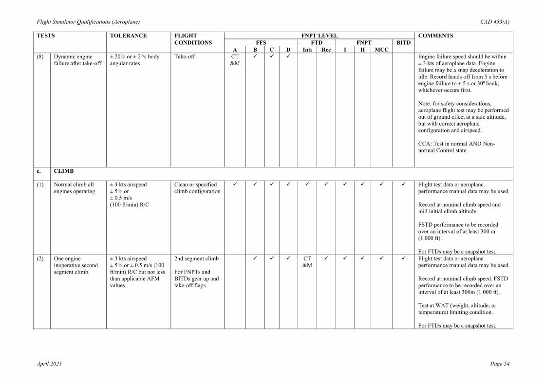
Flight Simulator Qualifications (Aeroplane) CAD 453(A)
April 2021 Page 54
TESTS TOLERANCE FLIGHT FNPT LEVEL COMMENTS CONDITIONS FFS FTD FNPT BITD A B C D Inti Rec I II MCC (8) Dynamic engine
failure after take-off. ± 20% or ± 2º/s body angular rates
Take-off CT &M
Engine failure speed should be within ± 3 kts of aeroplane data. Engine failure may be a snap deceleration to idle. Record hands off from 5 s before engine failure to + 5 s or 30º bank, whichever occurs first. Note: for safety considerations, aeroplane flight test may be performed out of ground effect at a safe altitude, but with correct aeroplane configuration and airspeed. CCA: Test in normal AND Non-normal Control state.
c. CLIMB
(1) Normal climb all engines operating
± 3 kts airspeed ± 5% or ± 0.5 m/s (100 ft/min) R/C
Clean or specified climb configuration
Flight test data or aeroplane performance manual data may be used. Record at nominal climb speed and mid initial climb altitude. FSTD performance to be recorded over an interval of at least 300 m (1 000 ft). For FTDs may be a snapshot test.
(2) One engine inoperative second segment climb.
± 3 kts airspeed ± 5% or ± 0.5 m/s (100 ft/min) R/C but not less than applicable AFM values.
2nd segment climb For FNPTs and BITDs gear up and take-off flaps
CT &M
Flight test data or aeroplane performance manual data may be used. Record at nominal climb speed. FSTD performance to be recorded over an interval of at least 300m (1 000 ft). Test at WAT (weight, altitude, or temperature) limiting condition. For FTDs may be a snapshot test.

Flight Simulator Qualifications (Aeroplane) CAD 453(A)
April 2021 Page 55
TESTS TOLERANCE FLIGHT FNPT LEVEL COMMENTS CONDITIONS FFS FTD FNPT BITD A B C D Inti Rec I II MCC (3) One engine
inoperative en- route climb.
± 10% time ± 10% distance ± 10% fuel used
Clean CT &M
Flight test data or aeroplane performance manual data may be used. Test for at least a1 550 m (5 000 ft) segment.
(4) One engine inoperative approach climb for aeroplanes with icing accountability if required by the flight manual for this phase of flight.
± 3 kts airspeed ± 5% or ± 0.5 m/s (100 ft/min) R/C but not less than AFM values
Approach Flight test data or aeroplane performance manual data may be used. FSTD performance to be recorded over an interval of at least 300 m (1 000 ft). Test near maximum certificated landing weight as may be applicable to an approach in icing conditions. Aeroplane should be configured with all anti-ice and de-ice systems operating normally, gear up and go-around flap. All icing accountability considerations, in accordance with the flight manual for an approach in icing conditions, should be applied.
d. CRUISE/DESCENT
(1) Level flight acceleration
± 5% time Cruise CT &M
Minimum of 50 kts increase using maximum continuous thrust rating or equivalent. For very small aeroplanes, speed change may be reduced to 80% of operational speed range.
(2) Level flight deceleration
± 5% time Cruise CT &M
Minimum of 50 kts decrease using idle power. For very small aeroplanes, speed change may be reduced to 80% of operational speed range.
(3) Cruise performance ± 0.05 EPR or ± 5% N1 or ± 5% torque ± 5% fuel flow
Cruise May be a single snapshot showing instantaneous fuel flow, or a minimum of two consecutive snapshots with a spread of at least three minutes in steady flight.
(4) Idle descent ± 3 kts airspeed ± 5% or ± 1.0 m/s (200 ft/min) R/D
Clean Idle power stabilised descent at normal descent speed at mid altitude. Flight simulator performance to be recorded over an interval of at least 300 m (1 000 ft).

Flight Simulator Qualifications (Aeroplane) CAD 453(A)
April 2021 Page 56
TESTS TOLERANCE FLIGHT FNPT LEVEL COMMENTS CONDITIONS FFS FTD FNPT BITD A B C D Inti Rec I II MCC (5) Emergency descent ± 5 kts airspeed
± 5% or ± 1.5 m/s (300 ft/min) R/D
As per AFM Stabilised descent to be conducted with speedbrakes extended if applicable, at mid altitude and near VMO or according to emergency descent procedure. Flight simulator performance to be recorded over an interval of at least 900 m (3 000 ft).
e. STOPPING
(1) Deceleration time and distance, manual wheel brakes, dry runway, no reverse thrust.
± 5% or ± 1.5 s time. For distances up to 1 220 m (4 000 ft) ± 61 m (200 ft) or ± 10%, whichever is the smaller. For distances greater than 1 220 m (4 000 ft) ± 5% distance.
Landing CT &M
Time and distance should be recorded for at least 80% of the total time from touchdown to a full stop. Data required for medium and near maximum certificated landing weight. Engineering data may be used for the medium weight condition. Brake system pressure should be recorded.
(2) Deceleration time and distance, reverse thrust, no wheel brakes, dry runway.
± 5% or ± 1.5 s time and the smaller of ± 10% or ± 61 m (200 ft) of distance.
Landing CT &M
Time and distance should be recorded for at least 80% of the total time from initiation of reverse thrust to full thrust reverser minimum operating speed. Data required for medium and near maximum certificated landing weights. Engineering data may be used for the medium weight condition.
(3) Stopping distance, wheel brakes, wet runway.
± 10% o r± 61 m (200 ft) distance
Landing Either flight test or manufacturers performance manual data should be used where available. Engineering data, based on dry runway flight test stopping distance and the effects of contaminated runway braking coefficients , are an acceptable alternative

Flight Simulator Qualifications (Aeroplane) CAD 453(A)
April 2021 Page 57
TESTS TOLERANCE FLIGHT FNPT LEVEL COMMENTS CONDITIONS FFS FTD FNPT BITD A B C D Inti Rec I II MCC (4) Stopping distance,
wheel brakes, icy runway.
± 10% or ± 61 m (200 ft) distance
Landing Either flight test or manufacturer’s performance manual data should be used where available. Engineering data, based on dry runway flight test stopping distance and the effects of contaminated runway braking coefficients, are an acceptable alternative.
f. ENGINES
(1) Acceleration ± 10% Ti or ± 0.5s ± 10% Tt
Approach or landing
CT &M
Ti = Total time from initial throttle movement until a 10% response of a critical engine parameter. Tt = Total time from initial throttle movement to 90% of go around power. Critical engine parameter should be a measure of power (N1, N2, EPR, etc.). Plot from flight idle to go around power for a rapid throttle movement. FTD, FNPT and BITD only: CT&M acceptable.
(2) Deceleration ± 10% TI or ± 0.25s ± 10% Tt
Ground CT &M
Ti = Total time from initial throttle movement until a10% response of a critical engine parameter. Tt = Total time from initial throttle movement to 90% decay of maximum take-off power. Plot from maximum take-off power to idle for a rapid throttle movement. FTD, FNPT and BITD only: CT&M acceptable.

Flight Simulator Qualifications (Aeroplane) CAD 453(A)
April 2021 Page 58
TESTS TOLERANCE FLIGHT FNPT LEVEL COMMENTS CONDITIONS FFS FTD FNPT BITD A B C D Inti Rec I II MCC 2. HANDLING
QUALITIES
a. STATIC CONTROL CHECKS
NOTE: Pitch, roll and yaw controller position versus force or time should be measured at the control. An alternative method is to instrument the FSTD in an equivalent manner to the flight test aeroplane. The force and position data from this instrumentation should be directly recorded and matched to the aeroplane data. Such a permanent installation could be used without any time for installation of external devices. CCA: Testing of position versus force is not applicable if forces are generated solely by use of aeroplane hardware in the FSTD.
(1) Pitch controller position versus force and surface position calibration.
± 0.9 daN (2 lbs) breakout. ± 2.2 daN (5 lbs) or ± 10% force. ± 2° elevator angle
Ground CT &M
Uninterrupted control sweep to stops should be validated (where possible) with in-flight data from tests such as longitudinal static stability, stalls, etc. Static and dynamic flight control tests should be accomplished at the same feel or impact pressures.
(2) Roll controller position vs. force and surface position calibration.
± 0.9 daN (2 lbs) breakout ± 1.3 daN (3 lbs) or ± 10% force ± 2º aileron angle ± 3º spoiler angle
Ground CT &M
Uninterrupted control sweep to stops. Should be validated with in-flight data from tests such as engine out trims, steady state sideslips, etc. Static and dynamic flight control tests should be accomplished at the same feel or impact pressures.
Wheel position vs. force only.
± 1.3 daN (3 lbs) or ± 10% Force
Cruise or approach FNPT 1 and BITD: Control forces and travel should broadly correspond to that of the replicated class of aeroplane
(3) Rudder pedal position vs. force and surface position calibration.
± 2.2 daN (5 lbs) breakout ± 2.2 daN (5 lbs) or ± 10% force ± 2º rudder angle
Ground CT &M
Uninterrupted control sweep to stops. Should be validated with in flight data from tests such as engine out trims, steady state sideslips, etc. Static and dynamic flight control tests should be accomplished at the same feel or impact pressures.

Flight Simulator Qualifications (Aeroplane) CAD 453(A)
April 2021 Page 59
TESTS TOLERANCE FLIGHT FNPT LEVEL COMMENTS CONDITIONS FFS FTD FNPT BITD A B C D Inti Rec I II MCC Pedal position vs.
force only. ± 2.2 daN (5 lbs) or ± 10% force.
Cruise or approach FNPT 1 and BITD: Control forces and travel should broadly correspond to that of the replicated class of aeroplane.
(4) Nosewheel steering controller and position force calibration.
± 0.9 daN (2 lbs) breakout ± 1.3 daN (3 lbs) or ± 10% force ± 2º NWA
Ground CT &M
Uninterrupted control sweep to stops.
(5) Rudder pedal steering calibration.
± 2º NWA Ground CT &M
Uninterrupted control sweep to stops.
(6) Pitch trim indicator vs. surface position calibration.
± 0.5⁰ of trim angle Ground Purpose of test is to compare flight simulator against design data or equivalent.
± 1⁰ of trim angle Ground BITD: Only applicable if appropriate trim settings are available, e.g. data from the AFM.
(7) Pitch trim rate. ± 10% or ± 0.5º/s trim rate (º/s)
Ground and approach
Trim rate to be checked at pilot primary induced trim rate (ground) and autopilot or pilot primary trim rate in flight at go- around flight conditions.
(8) Alignment of cockpit throttle lever vs. selected engine parameter.
± 5º of TLA or ± 3% N1 or ± 0.03 EPR or ± 3% torque For propeller-driven aeroplanes, where the propeller levers do not have angular travel, a tolerance of ± 2 cm (± 0.8 in) applies.
Ground Simultaneous recording for all engines. The tolerances apply against aeroplane data and between engines. For aeroplanes with throttle detents, all detents to be presented. In the case of propeller-driven aeroplanes, if an additional lever, usually referred to as the propeller lever, is present, it should also be checked. Where these levers do not have angular travel a tolerance of ± 2 cm (± 0.8 inches) applies. May be a series of snapshot tests
(9) Brake pedal position vs. force and brake system pressure calibration.
± 2.2 daN (5 lbs) or ± 10% force. ± 1.0 MPa (150 psi) or ± 10% brake system pressure.
Ground CT &M
Flight simulator computer output results may be used to show compliance. Relate the hydraulic system pressure to pedal position in a ground static test.
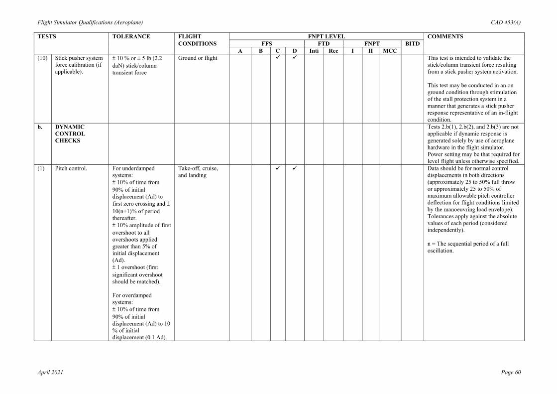
Flight Simulator Qualifications (Aeroplane) CAD 453(A)
April 2021 Page 60
TESTS TOLERANCE FLIGHT FNPT LEVEL COMMENTS CONDITIONS FFS FTD FNPT BITD A B C D Inti Rec I II MCC (10) Stick pusher system
force calibration (if applicable).
± 10 % or ± 5 lb (2.2 daN) stick/column transient force
Ground or flight This test is intended to validate the stick/column transient force resulting from a stick pusher system activation. This test may be conducted in an on ground condition through stimulation of the stall protection system in a manner that generates a stick pusher response representative of an in-flight condition.
b. DYNAMIC CONTROL CHECKS
Tests 2.b(1), 2.b(2), and 2.b(3) are not applicable if dynamic response is generated solely by use of aeroplane hardware in the flight simulator. Power setting may be that required for level flight unless otherwise specified.
(1) Pitch control. For underdamped systems: ± 10% of time from 90% of initial displacement (Ad) to first zero crossing and ± 10(n+1)% of period thereafter. ± 10% amplitude of first overshoot to all overshoots applied greater than 5% of initial displacement (Ad). ± 1 overshoot (first significant overshoot should be matched). For overdamped systems: ± 10% of time from 90% of initial displacement (Ad) to 10 % of initial displacement (0.1 Ad).
Take-off, cruise, and landing
Data should be for normal control displacements in both directions (approximately 25 to 50% full throw or approximately 25 to 50% of maximum allowable pitch controller deflection for flight conditions limited by the manoeuvring load envelope). Tolerances apply against the absolute values of each period (considered independently). n = The sequential period of a full oscillation.

Flight Simulator Qualifications (Aeroplane) CAD 453(A)
April 2021 Page 61
TESTS TOLERANCE FLIGHT FNPT LEVEL COMMENTS CONDITIONS FFS FTD FNPT BITD A B C D Inti Rec I II MCC (2) Roll control For underdamped
systems: ± 10% of time from 90% of initial displacement (Ad) to first zero crossing and (n+1)% of period thereafter. ± 10% amplitude of first overshoot applied to all overshoots greater than 5% of initial displacement (Ad). ± 1 overshoot (first significant overshoot should be matched). For overdamped systems: ± 10% of time from 90% of initial displacement (Ad) to 10% of initial displacement (0.1 Ad).
Take-off, cruise, and landing
Data should be for normal control displacement (approximately 25 to 50% of full throw or approximately 25 to 50% of maximum allowable roll controller deflection for flight conditions limited the manoeuvring load envelope).

Flight Simulator Qualifications (Aeroplane) CAD 453(A)
April 2021 Page 62
TESTS TOLERANCE FLIGHT FNPT LEVEL COMMENTS CONDITIONS FFS FTD FNPT BITD A B C D Inti Rec I II MCC (3) Yaw control For underdamped
systems: ± 10% of time from 90% of initial displacement (Ad) to first zero crossing and ± 10 (n+1)% of period thereafter. ± 10% amplitude of first overshoot applied to all overshoots greater than 5% of initial displacement (Ad). ± 1 overshoot (first significant overshoot should be matched). For overdamped systems: ± 10% of time from 90% of initial displacement (Ad) to 10% of initial displacement (0.1 Ad).
Take-off, cruise, and landing
Data should be for normal displacement (approximately 25 to 50% of full throw).
(4) Small control inputs - pitch.
± 0.15º /s body pitch rate or ± 20% of peak body pitch rate applied throughout the time history.
Approach or landing
Control inputs should be typical of minor corrections made while established on an ILS approach (approximately 0.5 to 2º/s pitch rate). Test in both directions. Show time history data from 5 s before until at least 5 s after initiation of control input. CCA: Test in normal AND non-normal control state.
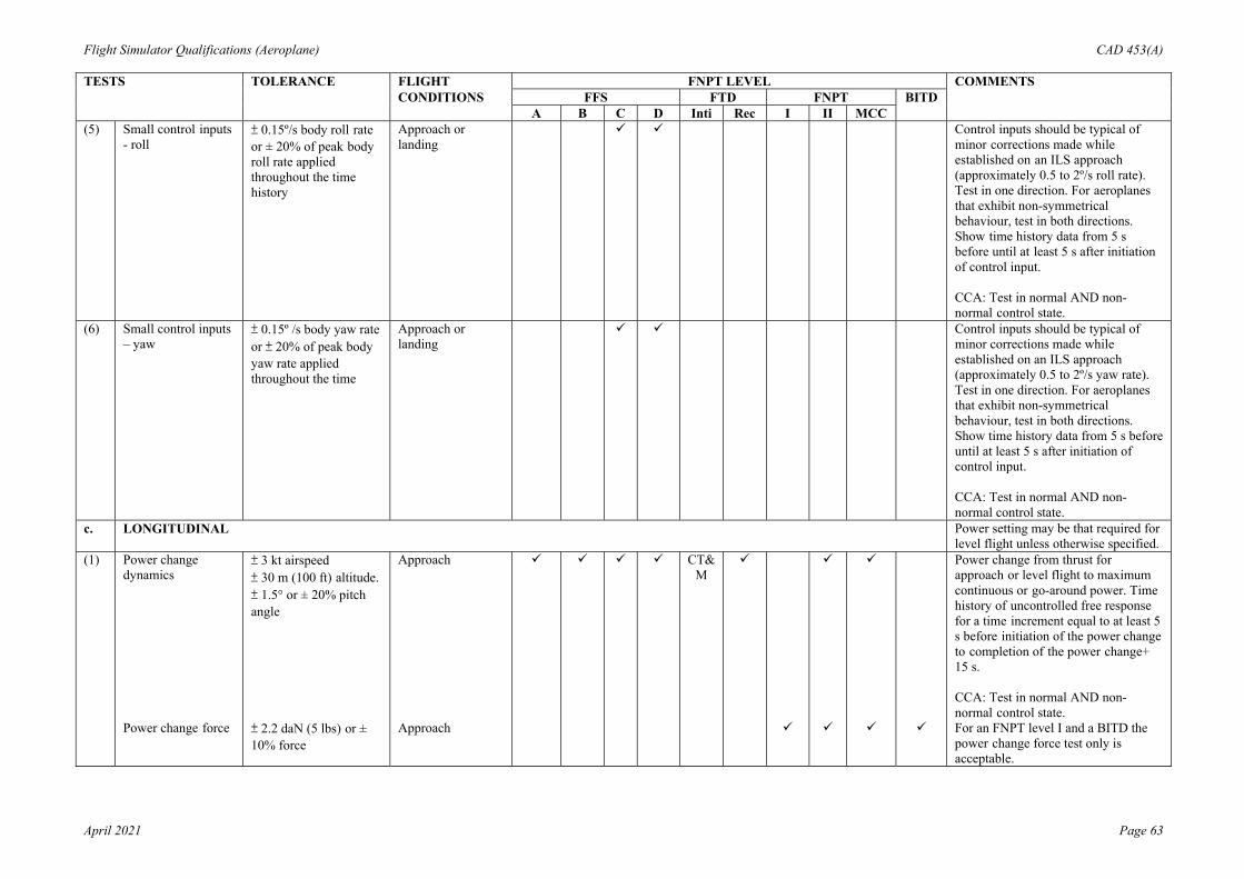
Flight Simulator Qualifications (Aeroplane) CAD 453(A)
April 2021 Page 63
TESTS TOLERANCE FLIGHT FNPT LEVEL COMMENTS CONDITIONS FFS FTD FNPT BITD A B C D Inti Rec I II MCC (5) Small control inputs
- roll ± 0.15º/s body roll rate or ± 20% of peak body roll rate applied throughout the time history
Approach or landing
Control inputs should be typical of minor corrections made while established on an ILS approach (approximately 0.5 to 2º/s roll rate). Test in one direction. For aeroplanes that exhibit non-symmetrical behaviour, test in both directions. Show time history data from 5 s before until at least 5 s after initiation of control input. CCA: Test in normal AND non-normal control state.
(6) Small control inputs – yaw
± 0.15º /s body yaw rate or ± 20% of peak body yaw rate applied throughout the time
Approach or landing
Control inputs should be typical of minor corrections made while established on an ILS approach (approximately 0.5 to 2º/s yaw rate). Test in one direction. For aeroplanes that exhibit non-symmetrical behaviour, test in both directions. Show time history data from 5 s before until at least 5 s after initiation of control input. CCA: Test in normal AND non-normal control state.
c. LONGITUDINAL Power setting may be that required for level flight unless otherwise specified.
(1) Power change dynamics
± 3 kt airspeed ± 30 m (100 ft) altitude. ± 1.5° or ± 20% pitch angle
Approach CT&M
Power change from thrust for approach or level flight to maximum continuous or go-around power. Time history of uncontrolled free response for a time increment equal to at least 5 s before initiation of the power change to completion of the power change+ 15 s. CCA: Test in normal AND non-normal control state.
Power change force ± 2.2 daN (5 lbs) or ± 10% force
Approach For an FNPT level I and a BITD the power change force test only is acceptable.
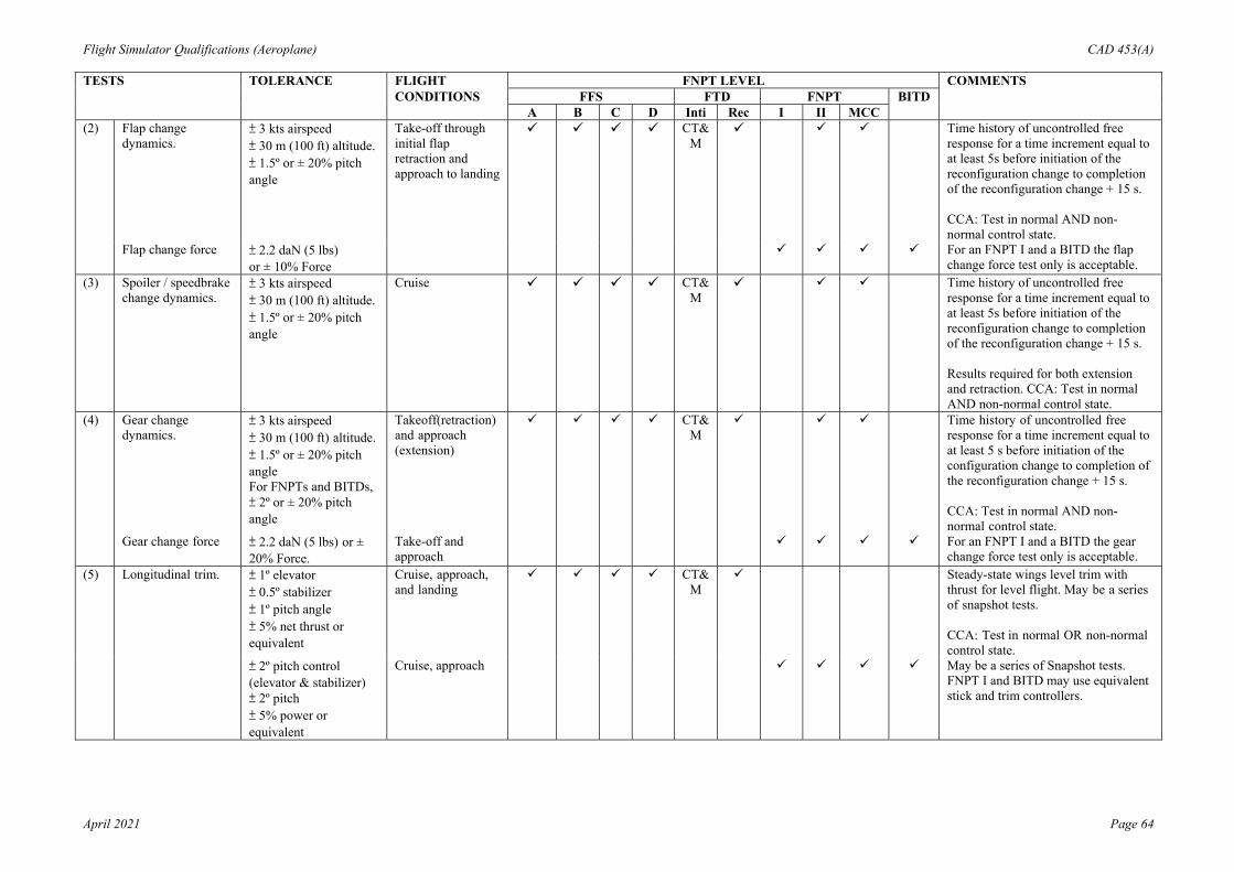
Flight Simulator Qualifications (Aeroplane) CAD 453(A)
April 2021 Page 64
TESTS TOLERANCE FLIGHT FNPT LEVEL COMMENTS CONDITIONS FFS FTD FNPT BITD A B C D Inti Rec I II MCC (2) Flap change
dynamics. ± 3 kts airspeed ± 30 m (100 ft) altitude. ± 1.5º or ± 20% pitch angle
Take-off through initial flap retraction and approach to landing
CT&M
Time history of uncontrolled free response for a time increment equal to at least 5s before initiation of the reconfiguration change to completion of the reconfiguration change + 15 s. CCA: Test in normal AND non-normal control state.
Flap change force ± 2.2 daN (5 lbs) or ± 10% Force
For an FNPT I and a BITD the flap change force test only is acceptable.
(3) Spoiler / speedbrake change dynamics.
± 3 kts airspeed ± 30 m (100 ft) altitude. ± 1.5º or ± 20% pitch angle
Cruise CT&M
Time history of uncontrolled free response for a time increment equal to at least 5s before initiation of the reconfiguration change to completion of the reconfiguration change + 15 s. Results required for both extension and retraction. CCA: Test in normal AND non-normal control state.
(4) Gear change dynamics.
± 3 kts airspeed ± 30 m (100 ft) altitude. ± 1.5º or ± 20% pitch angle For FNPTs and BITDs, ± 2º or ± 20% pitch angle
Takeoff(retraction) and approach (extension)
CT&M
Time history of uncontrolled free response for a time increment equal to at least 5 s before initiation of the configuration change to completion of the reconfiguration change + 15 s. CCA: Test in normal AND non-normal control state.
Gear change force ± 2.2 daN (5 lbs) or ± 20% Force.
Take-off and approach
For an FNPT I and a BITD the gear change force test only is acceptable.
(5) Longitudinal trim. ± 1º elevator ± 0.5º stabilizer ± 1º pitch angle ± 5% net thrust or equivalent
Cruise, approach, and landing
CT&M
Steady-state wings level trim with thrust for level flight. May be a series of snapshot tests. CCA: Test in normal OR non-normal control state.
± 2º pitch control (elevator & stabilizer) ± 2º pitch ± 5% power or equivalent
Cruise, approach May be a series of Snapshot tests. FNPT I and BITD may use equivalent stick and trim controllers.

Flight Simulator Qualifications (Aeroplane) CAD 453(A)
April 2021 Page 65
TESTS TOLERANCE FLIGHT FNPT LEVEL COMMENTS CONDITIONS FFS FTD FNPT BITD A B C D Inti Rec I II MCC (6) Longitudinal
manoeuvring stability (stick force/g).
± 2.2 daN (5 lbs) or ± 10% pitch controller force Alternative method: ± 1º or ± 10% change of elevator
Cruise, approach, and landing
Continuous time history data or a series of snapshot tests may be used. Test up to approximately 30º of bank for approach and landing configurations. Test up to approximately 45º of bank for the cruise configuration. Force tolerance not applicable if forces are generated solely by the use of aeroplane hardware in the FSTD. Alternative method applies to aeroplanes which do not exhibit stick- force-per-g characteristics. CCA: Test in normal AND non-normal control state as applicable.
(7) Longitudinal static stability.
± 2.2 daN (5 lbs) or± 10% pitch controller force. Alternative method ± 1º or ± 10% change of elevator
Approach Data for at least two speeds above and two speeds below trim speed. May be a series of snapshot tests. Force tolerance not applicable if forces are generated solely by the use of aeroplane hardware in the FSTD. Alternative method applies to aeroplanes which do not exhibit speed stability characteristics. CCA: Test in normal OR non-normal control state as applicable.

Flight Simulator Qualifications (Aeroplane) CAD 453(A)
April 2021 Page 66
TESTS TOLERANCE FLIGHT FNPT LEVEL COMMENTS CONDITIONS FFS FTD FNPT BITD A B C D Inti Rec I II MCC (8a) Stall characteristics. ± 3 kt airspeed for stall
warning and stall speeds. ± 2° angle of attack for the buffet threshold of perception and for the initial buffet based upon the Nz component. Control inputs must be plotted and demonstrate correct trend and magnitude. Approach to stall: ± 2.0° pitch angle; ± 2.0° angle of attack; and ± 2.0° bank angle. Stall warning up to stall: ± 2.0° pitch angle; ± 2.0º angle of attack; and correct trend and magnitude for roll rate and yaw rate.
2nd segment climb, high- altitude cruise (near performance limited condition) and approach or landing
For CCA aeroplanes with stall envelope protection systems: test in normal and non-normal control states. In normal control state, it is expected that envelope protections will take effect, and it may not be possible to reach the aerodynamic stall condition for some aeroplanes. The test is only required for an angle of attack range necessary to demonstrate the correct operation of the system. These tests may be used to satisfy the required (angle of attack) flight manoeuvre and envelope protection tests (2.h.(6)). In non-normal state, it is necessary to perform the test to the aerodynamic stall. It is understood that flight test data may not be available and, in this circumstance, engineering validation data may be used and the extent of the test should be adequate to allow training through to recovery, in accordance with the training objectives. For safety of flight considerations, the flight test data may be limited to the stall angle of attack, and the modelling beyond the stall angle of attack is only required to ensure it is limited to continuity and completion of the recovery. Applicable only for those FSTDs that are to be qualified for full stall training tasks.

Flight Simulator Qualifications (Aeroplane) CAD 453(A)
April 2021 Page 67
TESTS TOLERANCE FLIGHT FNPT LEVEL COMMENTS CONDITIONS FFS FTD FNPT BITD A B C D Inti Rec I II MCC (8b) Approach-to- stall
characteristics ± 3 kt airspeed for stall warning speeds. ± 2.0° angle of attack for initial buffet: ± 2.0° pitch angle; ± 2.0° angle of attack; and ± 2.0° bank angle. Additionally, for those aeroplanes with reversible flight control systems: ±10 % or ± 5 lb (2.2 daN)) stick/column force.
Second- segment climb, high-altitude cruise (near performance limited condition) and approach or landing
See (1)
See (1)
CCA: Test in normal and non-normal control states. For FTDs, flight conditions required for second-segment climb and approach or landing only. Note (1): For FSTDs not qualified to conduct full stall training tasks.
(9) Phugoid dynamics. ± 10% period. ± 10% time to ½ or double amplitude or ± 0.02 of damping ratio.
Cruise Test should include three full cycles or that necessary to determine time to ½ or double amplitude, whichever is less. CCA: Test in non-normal control state.
± 10% period with representative damping.
Cruise Test should include at least three full cycles. Time history recommended.
(10) Short-period dynamics.
± 1.5° pitch angle or± 2°/s pitch rate. ± 0.1 g normal acceleration.
Cruise CCA: Test in normal AND non-normal control state.
d. LATERAL DIRECTIONAL

Flight Simulator Qualifications (Aeroplane) CAD 453(A)
April 2021 Page 68
TESTS TOLERANCE FLIGHT FNPT LEVEL COMMENTS CONDITIONS FFS FTD FNPT BITD A B C D Inti Rec I II MCC (1) Minimum control
speed, air (VMCA or VMCL), per applicable airworthiness standard, or low speed engine inoperative handling characteristics in the air.
± 3 kt airspeed Take-off or landing(whichever is most critical in the aeroplane)
CT &M
CT&M
Minimum speed may be defined by a performance or control limit which prevents demonstration of VMC or VMCL in the conventional manner. Take-off thrust should be set on the operating engine(s). Time history or snapshot data may be used. CCA: Test in normal OR non-normal control state. FNPTs and BITDs: It is important that there exists a realistic speed relationship between Vmca and Vs for all configurations and in particular the most critical full-power engine-out take-off configurations.
(2) Roll response(rate). ± 10 % or ± 2°/s roll rate FS only: For aeroplanes with reversible flight control systems: ± 10% or ± 1.3 daN (3 lb) roll controller force.
Cruise and approach or landing
CT&M
Test with normal roll control displacement (about 30% of maximum control wheel). May be combined with step input of flight deck roll controller test 2.d(3).
(3) Step input of cockpit roll controller (or roll overshoot).
± 10% or ± 2° bank angle
Approach or landing
CT&M
With wings level, apply a step roll control input using approximately one-third of roll controller travel. At approximately 20° to 30° bank, abruptly return the roll controller to neutral and allow at least 10 s of aeroplane free response. May be combined with roll response (rate) test. 2.d.(2). CCA: Test in normal AND non-normal control state.
(4) Spiral stability. Correct trend and ± 2º or ± 10 % bank angle in 20s. If alternate test is used: correct trend and ± 2° aileron.
Cruise and approach or landing Cruise
CT&M
Aeroplane data averaged from multiple tests may be used. Test for both directions. As an alternative test, show lateral control required to maintain a steady turn with a bank angle of approximately 30º. CCA: Test in non-normal control state.

Flight Simulator Qualifications (Aeroplane) CAD 453(A)
April 2021 Page 69
TESTS TOLERANCE FLIGHT FNPT LEVEL COMMENTS CONDITIONS FFS FTD FNPT BITD A B C D Inti Rec I II MCC (5) Engine inoperative
trim. ± 1º rudder angle or ± 1º tab angle or equivalent pedal. ± 2º sideslip angle.
2nd segment climb and approach or landing
CT&M
Test should be performed in a manner similar to that for which a pilot is trained to trim an engine failure condition. 2nd segment climb test should be at take-off thrust. Approach or landing test should be at thrust for level flight. May be snapshot tests.
(6) Rudder response. ± 2º/s or ± 10% yaw rate
Approach or landing
Test with stability augmentation ON and OFF. For FNPT and BITD: test with stability augmentation OFF only. Test with a step input at approximately 25% of full rudder pedal throw. CCA: Test in normal AND non-normal control state.
± 2º/s or ± 10 % yaw rate or ± 10% heading change
(7) Dutch roll (yaw damper OFF).
± 0.5 s or ± 10% of period. ± 10% of time to ½ or double amplitude or ± 0.02 of damping ratio. ± 20% or ± 1 s of time difference between peaks of bank and sideslip
Cruise and approach or landing
Test for at least six cycles with stability augmentation OFF. CCA: Test in non-normal control state.
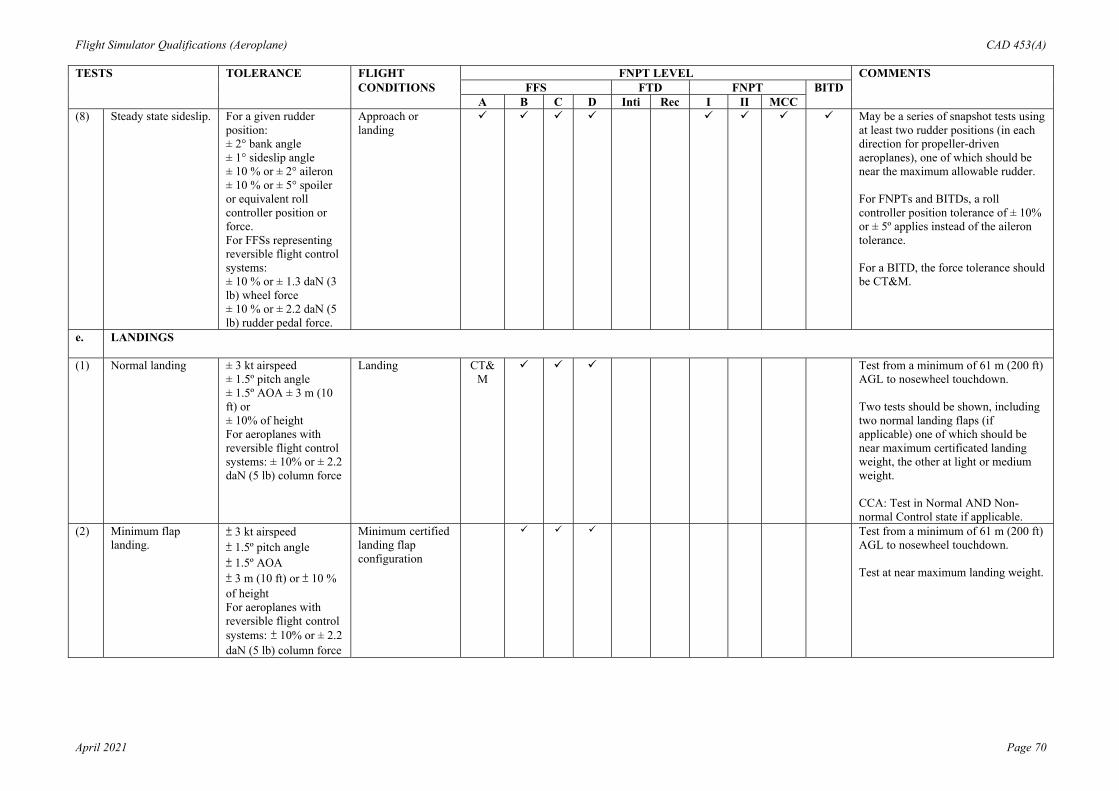
Flight Simulator Qualifications (Aeroplane) CAD 453(A)
April 2021 Page 70
TESTS TOLERANCE FLIGHT FNPT LEVEL COMMENTS CONDITIONS FFS FTD FNPT BITD A B C D Inti Rec I II MCC (8) Steady state sideslip. For a given rudder
position: ± 2° bank angle ± 1° sideslip angle ± 10 % or ± 2° aileron ± 10 % or ± 5° spoiler or equivalent roll controller position or force. For FFSs representing reversible flight control systems: ± 10 % or ± 1.3 daN (3 lb) wheel force ± 10 % or ± 2.2 daN (5 lb) rudder pedal force.
Approach or landing
May be a series of snapshot tests using at least two rudder positions (in each direction for propeller-driven aeroplanes), one of which should be near the maximum allowable rudder. For FNPTs and BITDs, a roll controller position tolerance of ± 10% or ± 5º applies instead of the aileron tolerance. For a BITD, the force tolerance should be CT&M.
e. LANDINGS
(1) Normal landing ± 3 kt airspeed ± 1.5º pitch angle ± 1.5º AOA ± 3 m (10 ft) or ± 10% of height For aeroplanes with reversible flight control systems: ± 10% or ± 2.2 daN (5 lb) column force
Landing CT&M
Test from a minimum of 61 m (200 ft) AGL to nosewheel touchdown. Two tests should be shown, including two normal landing flaps (if applicable) one of which should be near maximum certificated landing weight, the other at light or medium weight. CCA: Test in Normal AND Non-normal Control state if applicable.
(2) Minimum flap landing.
± 3 kt airspeed ± 1.5º pitch angle ± 1.5º AOA ± 3 m (10 ft) or ± 10 % of height For aeroplanes with reversible flight control systems: ± 10% or ± 2.2 daN (5 lb) column force
Minimum certified landing flap configuration
Test from a minimum of 61 m (200 ft) AGL to nosewheel touchdown. Test at near maximum landing weight.

Flight Simulator Qualifications (Aeroplane) CAD 453(A)
April 2021 Page 71
TESTS TOLERANCE FLIGHT FNPT LEVEL COMMENTS CONDITIONS FFS FTD FNPT BITD A B C D Inti Rec I II MCC (3) Crosswind landing. ± 3 kt airspeed
± 1.5º pitch angle ± 1.5º AOA ± 3 m (10 ft) or ± 10 % height ± 2º bank angle ± 2º sideslip angle ± 3º heading angle For aeroplanes with reversible flight control systems: ± 10% or ± 2.2 daN (5 lb) column force ± 10% or ± 1.3 daN (3 lb) wheel force ± 10% or ± 2.2 daN (5 lb) rudder pedal force.
Landing Test from a minimum of 61 m (200 ft) AGL to a 50 % decrease in main landing gear touchdown speed. Requires test data, including wind profile, for a crosswind component of at least 60% of AFM value measured at10 m (33 ft) above the runway.
(4) One engine inoperative landing.
± 3 kt airspeed ± 1.5º pitch angle ± 1.5º AOA ± 3 m (10 ft) or ± 10% height ± 2º bank angle ± 2º sideslip angle ± 3º heading angle
Landing Test from a minimum of 61 m of 61 m AGL to a 50% decrease in main landing gear touchdown speed.
(5) Autopilot landing (if applicable).
± 1.5 m (5 ft) flare height. ± 0.5 s or ± 10% Tf. ± 0.7 m/s (140 ft/min) R/D at touchdown. ± 3 m (10 ft) lateral deviation during rollout.
Landing If autopilot provides rollout guidance, record lateral deviation from touchdown to a 50% decrease in main landing gear touchdown speed. Time of autopilot flare mode engage and main gear touchdown should be noted. This test is not a substitute for the ground effects test requirement. Tf = Duration of flare
(6) All engine autopilot go around.
± 3 kt airspeed ± 1.5 pitch angle ± 1.5 AOA
As per AFM Normal all engine autopilot go around should be demonstrated (if applicable) at medium weight. CCA: Test in normal AND non-normal.

Flight Simulator Qualifications (Aeroplane) CAD 453(A)
April 2021 Page 72
TESTS TOLERANCE FLIGHT FNPT LEVEL COMMENTS CONDITIONS FFS FTD FNPT BITD A B C D Inti Rec I II MCC (7) One-engine-
inoperative go- around
± 3 kt airspeed ±1.5 pitch angle ±1.5 AOA ± 2 bank angle ± 2 sideslip angle
As per AFM Engine inoperative go-around required near maximum certificated landing weight with critical engine(s) inoperative. Provide one test with autopilot (if applicable) and one without autopilot. CCA: Non-autopilot test to be conducted in non-normal mode.
(8) Directional control (rudder effectiveness) with reverse thrust symmetric).
± 5 kt airspeed ± 2/s yaw rate
Landing Apply rudder pedal input in both directions using full reverse thrust until reaching full thrust reverser minimum operating speed.
(9) Directional control (rudder effectiveness) with reverser thrust(asymmetric)
± 5 kt airspeed ± 3 heading angle
Landing With full reverse thrust on the operating engine(s), maintain heading with rudder pedal input until maximum rudder pedal input or thrust reverser minimum operating speed is reached.
f. GROUND EFFECT
(1) A test to demonstrate ground effect.
± 1° elevator ± 0.5° stabiliser angle. ± 5% net thrust or equivalent. ± 1° AOA ± 1.5 m (5 ft) or ± 10% height ± 3 kt airspeed ± 1° pitch angle
Landing A rationale should be provided with justification of results. CCA: Test in normal OR non-normal control state.

Flight Simulator Qualifications (Aeroplane) CAD 453(A)
April 2021 Page 73
TESTS TOLERANCE FLIGHT FNPT LEVEL COMMENTS CONDITIONS FFS FTD FNPT BITD A B C D Inti Rec I II MCC g. WIND SHEAR
(1) Four Tests, two take-off and two landing with one of each conducted in still air and the other with Wind Shear active to demonstrate wind shear models.
None Take-off and landing
Wind shear models are required which provide training in the specific skills required for recognition of wind shear phenomena and execution of recovery manoeuvres. Wind shear models should be representative of measured or accident derived winds, but may be simplifications which ensure repeatable encounters. For example, models may consist of independent variable winds in multiple simultaneous components Wind models should be available for the following critical phases of flight: prior to take-off rotation; at lift-off; during initial climb; short final approach. The United States Federal Aviation Administration (FAA) Wind shear Training Aid, wind models from the Royal Aerospace Establishment (RAE), the United States JAWS Project or other recognised sources may be implemented and should be supported and properly referenced in the QTG. Wind models from alternate sources may also be used if supported by aeroplane-related data and such data are properly supported and referenced in the QTG. Use of alternate data should be coordinated with the HK CAD prior to submittal of the QTG for approval.

Flight Simulator Qualifications (Aeroplane) CAD 453(A)
April 2021 Page 74
TESTS TOLERANCE FLIGHT FNPT LEVEL COMMENTS CONDITIONS FFS FTD FNPT BITD A B C D Inti Rec I II MCC h. FLIGHT AND
MANOEUVRE ENVELOPE PROTECTION FUNCTIONS
This paragraph is only applicable to computer-controlled aeroplanes. Time history results of response to control inputs during entry into each envelope protection function (i.e., with normal and degraded control states if function is different) are required. Set thrust as required to reach the envelope protection function.
(1) Overspeed. ± 5 kt airspeed Cruise (2) Minimum speed. ± 3 kt airspeed Take-off, and
approach cruise or landing
(3) Load factor. ± 0.1 g Take-off, cruise (4) Pitch angle ± 1.5º pitch angle Cruise, approach (5) Bank angle. ± 2º or ± 10 % bank
angle Approach
(6) Angle of attack ± 1.5º AOA Second segment climb and approach or landing
i. ENGINE AND AIRFRAME ICING EFFECTS
(1) Engine and airframe icing effects Demonstration (high angle of attack)
Take-off or approach or landing (one flight condition, two tests: ice on and ice off)

Flight Simulator Qualifications (Aeroplane) CAD 453(A)
April 2021 Page 75
TESTS TOLERANCE FLIGHT FNPT LEVEL COMMENTS CONDITIONS FFS FTD FNPT BITD A B C D Inti Rec I II MCC 3. MOTION
SYSTEM
a. Frequency response
As specified by the applicant for FFS qualification.
n/a Appropriate test to demonstrate the frequency response required.
b. Leg balance As specified by the applicant for FFS qualification.
n/a Appropriate test to demonstrate leg balance required .
c. Turn-around check
As specified by the applicant for FFS qualification.
n/a Appropriate test to demonstrate turn- around required.
d. Motion effects e. Motion system
repeatability ± 0.05 g actual platform linear accelerations
None Ensure that motion system hardware and software (in normal flight simulator operating mode) continue to perform as originally qualified. Performance changes from the original baseline can be readily identified with this information.
f. Motion cueing performance signature.
None Ground and flight For a given set of flight simulation manoeuvres record the relevant motion critical variables. These tests should be run with the motion buffet module disabled.
g. Characteristic motion vibrations
None Ground and flight The recorded test results for characteristic buffets should allow the comparison of relative amplitude versus frequency. For atmospheric disturbance testing, general purpose disturbance models that approximate demonstrable flight test data are acceptable. Principally, the flight simulator results should exhibit the overall appearance and trends of the aeroplane plots, with at least some of the frequency ‘spikes’ being present within 1 or 2 Hz of the aeroplane data.

Flight Simulator Qualifications (Aeroplane) CAD 453(A)
April 2021 Page 76
TESTS TOLERANCE FLIGHT FNPT LEVEL COMMENTS CONDITIONS FFS FTD FNPT BITD A B C D Inti Rec I II MCC The following tests
with recorded results and an SOC are required for characteristic motion vibrations, which can be sensed at the flight deck where applicable by aeroplane type:
(1) Thrust effects with brakes set
n/a Ground Test should be conducted at maximum possible thrust with brakes set
(2) Landing gear extended buffet
n/a Flight Test condition should be for a normal operational speed and not at the gear limiting speed.
(3) Flaps extended buffet
n/a Flight Test condition should be for a normal operational speed and not at the flap limiting speed.
(4) Speed brake deployed buffet
n/a Flight
(5) Stall buffet n/a Cruise (high altitude), second-segment climb, and approach or landing
Test required only for FSTDs that are to be qualified for full stall training tasks or for those aeroplanes which exhibit stall buffet before the activation of the stall warning system. Tests must be conducted for an angle of attack range between the buffet threshold of perception to the pilot and the stall angle of attack. Post-stall characteristics are not required. If stabilised flight data between buffet threshold of perception and stall angle of attack are not available, PSD analysis should be conducted for a time span between initial buffet and stall angle of attack.
(6) High speed or Mach buffet
n/a Flight Test condition should be for high-speed manoeuvre buffet/wind-up-turn or alternatively Mach buffet.
(7) In-flight vibrations n/a Flight (clean configuration)
Test should be conducted to be representative of in-flight vibrations for propeller-driven aeroplanes.

Flight Simulator Qualifications (Aeroplane) CAD 453(A)
April 2021 Page 77
TESTS TOLERANCE FLIGHT FNPT LEVEL COMMENTS CONDITIONS FFS FTD FNPT BITD A B C D Inti Rec I II MCC 4. VISUAL SYSTEM a. SYSTEM
RESPONSE TIME
(1) Transport delay 150 ms or less after controller movement.
Pitch, roll and yaw One separate test is required in each axis.
300 ms or less after controller movement.
For FNPT I and BITD, only the instrument response time applies.
-- or -- (2) Latency 150 ms or less after
controller movement. Take-off, cruise, and
One test is required in each axis (pitch, roll, yaw) for each of the three conditions compared with aeroplane
300 ms or less after controller movement.
approach or landing
data for a similar input. The visual or test pattern used during the response scene testing should be representative of the required system capacities to meet the daylight, twilight (dusk/dawn) and night visual capability as applicable. FFS only: Response tests should be confirmed in daylight, twilight and night settings as applicable. For FNPT I and BITD, only the instrument response time applies.

Flight Simulator Qualifications (Aeroplane) CAD 453(A)
April 2021 Page 78
TESTS TOLERANCE FLIGHT FNPT LEVEL COMMENTS CONDITIONS FFS FTD FNPT BITD A B C D Inti Rec I II MCC b. DISPLAY
SYSTEM TESTS
(1) (a) Continuous
collimated cross- cockpit visual field of view
Continuous, cross- cockpit, minimum collimated visual field of view providing each pilot with 180º horizontal and 40º vertical field of view. Horizontal FOV: Not less than a total of 176 measured degrees (including not less than 88 measured degrees either side of the centre of the design eye point). Vertical FOV: Not less than a total of 36 measured degrees from the pilot’s and co-pilot’s eye point.
n/a Field of view should be measured using a visual test pattern filling the entire visual scene (all channels) consisting of a matrix of black and white 5º squares. Installed alignment should be confirmed in a statement of compliance.
(b) Continuous collimated visual field of view
Continuous, minimum collimated visual field of view providing each pilot with 45º horizontal and 30º vertical field of view
n/a
(2) System geometry 5º even angular spacing within ±1º as measured from either pilot eye-point, and within 1.5 for adjacent squares.
n/a System geometry should be measured using a visual test pattern filling the entire visual scene (all channels) consisting of a matrix of black and white 5º squares with light points at the intersections. The operator should demonstrate that the angular spacing of any chosen 5º square and the relative spacing of adjacent squares are within the stated tolerances. The intent of this test is to demonstrate local linearity of the displayed image at either pilot eye- point.

Flight Simulator Qualifications (Aeroplane) CAD 453(A)
April 2021 Page 79
TESTS TOLERANCE FLIGHT FNPT LEVEL COMMENTS CONDITIONS FFS FTD FNPT BITD A B C D Inti Rec I II MCC (3) Surface contrast
ratio Not less than 5:1 n/a Surface contrast ratio should be
measured using a raster drawn test pattern filling the entire visual scene (all channels). The test pattern should consist of black and white squares, five per square with a white square in the centre of each channel. Measurement should be made on the centre bright square for each channel using a 1 spot photometer. This value should have a minimum brightness of 7 cd/m2 (2 foot-lamberts). Measure any adjacent dark squares. The contrast ratio is the bright square value divided by the dark square value. Note. During contrast ratio testing, simulator aft-cab and flight deck ambient light levels should be zero.
(4) Highlight brightness Not less than 20 cd/m2 (6ft-lamberts) on the display
n/a Highlight brightness should be measured by maintaining the full test pattern. Superimposing a highlight on the centre white square of each channel and measuring the brightness using the 1º spot photometer. Lightpoints are not acceptable. Use of calligraphic capabilities to enhance raster brightness is acceptable.
(5) Vernier resolution Not greater than 2 arc minutes
n/a Vernier resolution should be demonstrated by a test of objects shown to occupy the required visual angle in each visual display used on a scene from the pilot’s eye-point. The eye will subtend two arc minutes (arc tan (4/6 876) x60) when positioned on a3 degree glideslope, 6 876 ft slant range from the centrally located threshold of a black runway surface painted with white threshold bars that are 16 ft wide with 4 ft gaps in-between. This should be confirmed by calculations in a statement of compliance.
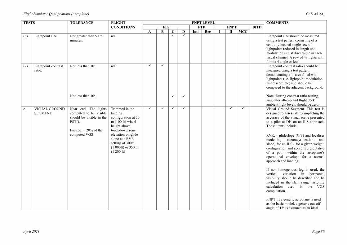
Flight Simulator Qualifications (Aeroplane) CAD 453(A)
April 2021 Page 80
TESTS TOLERANCE FLIGHT FNPT LEVEL COMMENTS CONDITIONS FFS FTD FNPT BITD A B C D Inti Rec I II MCC (6) Lightpoint size Not greater than 5 arc
minutes. n/a Lightpoint size should be measured
using a test pattern consisting of a centrally located single row of lightpoints reduced in length until modulation is just discernible in each visual channel. A row of 48 lights will form a 4 angle or less.
(7) Lightpoint contrast ratio.
Not less than 10:1 Not less than 10:1
n/a
Lightpoint contrast ratio should be measured using a test pattern demonstrating a 1º area filled with lightpoints (i.e. lightpoint modulation just discernible) and should be compared to the adjacent background. Note. During contrast ratio testing, simulator aft-cab and flight deck ambient light levels should be zero.
c. VISUAL GROUND SEGMENT
Near end. The lights computed to be visible should be visible in the FSTD. Far end: ± 20% of the computed VGS
Trimmed in the landing configuration at 30 m (100 ft) wheel height above touchdown zone elevation on glide slope at a RVR setting of 300m (1 000ft) or 350 m (1 200 ft)
Visual Ground Segment. This test is designed to assess items impacting the accuracy of the visual scene presented to a pilot at DH on an ILS approach. Those items include RVR, - glideslope (G/S) and localiser modelling accuracy(location and slope) for an ILS,- for a given weight, configuration and speed representative of a point within the aeroplane’s operational envelope for a normal approach and landing. If non-homogenous fog is used, the vertical variation in horizontal visibility should be described and be included in the slant range visibility calculation used in the VGS computation. FNPT: If a generic aeroplane is used as the basic model, a generic cut-off angle of 15º is assumed as an ideal.

Flight Simulator Qualifications (Aeroplane) CAD 453(A)
April 2021 Page 81
TESTS TOLERANCE FLIGHT FNPT LEVEL COMMENTS CONDITIONS FFS FTD FNPT BITD A B C D Inti Rec I II MCC 5. SOUND
SYSTEMS All tests in this section should be
presented using an unweighted1/3-octave band format from band 17 to42 (50 Hz to 16 kHz). A minimum 20 s average should be taken at the location corresponding to the aeroplane data set. The aeroplane and flight simulator results should be produced using comparable data analysis techniques.
a. TURBO-JET AEROPLANES
(1) Ready for engine start
± 5 dB per 1/3 octave band
Ground Normal condition prior to engine start. The APU should be on if appropriate.
(2) All engines at idle ± 5 dB per 1/3 octave band
Ground Normal condition prior to take-off.
(3) All engines at maximum allowable thrust with brakes set
± 5 dB per 1/3 octave band
Ground Normal condition prior to take-off.
(4) Climb ± 5 dB per 1/3 octave band
En-route climb Medium altitude.
(5) Cruise ± 5 dB per 1/3 octave band
Cruise Normal cruise configuration.
(6) Speedbrake/ spoilers extended (as appropriate)
± 5 dB per 1/3 octave band
Cruise Normal and constant speedbrake deflection for descent at a constant airspeed and power setting.
(7) Initial approach ± 5 dB per 1/3 octave band
Approach Constant airspeed, gear up, flaps/slats as appropriate.
(8) Final approach ± 5 dB per 1/3 octave band
Landing Constant airspeed, gear down, full flaps.
b. PROPELLER AEROPLANES
(1) Ready for engine start
± 5 dB per 1/3 octave band
Ground Normal condition prior to engine start. The APU should be on if appropriate.
(2) All propellers feathered
± 5 dB per 1/3 octave band
Ground Normal condition prior to take-off.
(3) Ground idle or equivalent
± 5 dB per 1/3 octave band
Ground Normal condition prior to take-off.
(4) Flight idle or equivalent
± 5 dB per 1/3 octave band
Ground Normal condition prior to take-off.

Flight Simulator Qualifications (Aeroplane) CAD 453(A)
April 2021 Page 82
TESTS TOLERANCE FLIGHT FNPT LEVEL COMMENTS CONDITIONS FFS FTD FNPT BITD A B C D Inti Rec I II MCC (5) All engines at
maximum allowable power with brakes set
± 5 dB per 1/3 octave band
Ground Normal condition prior to take-off.
(6) Climb ± 5 dB per 1/3 octave band
En-route climb Medium altitude.
(7) Cruise ± 5 dB per 1/3 octave band
Cruise Normal cruise configuration.
(8) Initial approach ± 5 dB per 1/3 octave band
Approach Constant airspeed, gear up, flaps extended as appropriate, RPM as per operations manual.
(9) Final approach ± 5 dB per 1/3 octave band
Landing Constant airspeed, gear down, full flaps, RPM as per operations manual.
c. SPECIAL CASES ± 5 dB per 1/3 octave band
Special cases identified as particularly significant to the pilot, important in training, or unique to a specific aeroplane type or variant.
d. FFS BACKGROUND NOISE
Initial evaluation: not applicable. Recurrent evaluation: 3 dB per 1/3 octave band compared to initial evaluation
Results of the background noise at initial qualification should be included in the QTG document and approved by the qualifying authority. The simulated sound will be evaluated to ensure that the background noise does not interfere with training. The measurements should be made with the simulation running, the sound muted and a dead cockpit.
e. FREQUENCY RESPONSE
Initial evaluation: not applicable. Recurrent evaluation: cannot exceed ± 5 dB on three consecutive bands when compared to initial evaluation and the average of the absolute differences between initial and recurrent evaluation results cannot exceed 2 dB.
Only required if the results are to be used during recurrent evaluations. The results should be acknowledged by CAD at initial qualification.

Flight Simulator Qualifications (Aeroplane) CAD 453(A)
April 2021 Page 83
CHAPTER 5 APPENDIX 2 SUPPLEMENTAL INFORMATION ON VALIDATION TESTS 1 Control Dynamics 1.1 The following points and methods of measurement should be considered:
1.1.1 The characteristics of an aeroplane flight control system have a major effect on handling qualities. A significant consideration in pilot acceptability of an aeroplane is the 'feel' provided through the cockpit controls. Considerable effort is expended on aeroplane feel system design in order to deliver a system with which pilots will be comfortable and consider the aeroplane desirable to fly. In order for a simulator to be representative, it too should present the pilot with the proper feel; that of the respective aeroplane. Compliance with this requirement should be determined by comparing a recording of the control feel dynamics of the simulator to aeroplane measurements in the take-off, cruise, and landing configurations.
1.1.2 Recordings such as free response to a pulse or step function are classically used to estimate the dynamic properties of electromechanical systems. In any case, it is only possible to estimate the dynamic properties as a result of only being able to estimate true inputs and responses. Therefore, it is imperative that the best possible data be collected since close matching of the simulator control loading system to the aeroplane systems is essential. The required control dynamics tests are indicated in Appendix 1, paragraph 2.b.(1) to (3).
1.1.3 For initial and upgrade evaluations, control dynamics characteristics should be measured at and recorded directly from the cockpit controls. This procedure is usually accomplished by measuring the free response of the controls using a step input or pulse input to excite the system. The procedure should be accomplished in the take-off, cruise, and landing flight conditions and configurations.
1.1.4 For aeroplanes with irreversible control systems, measurements may be obtained on the ground if proper pitot-static inputs are provided to represent airspeeds typical of those encountered in flight. Likewise, it may be shown that for some aeroplanes, take-off, cruise, and landing configurations have like effects. Thus, one may suffice for another. If either or both considerations apply, engineering validation or aeroplane manufacturer rationale should be submitted as justification for ground tests or for eliminating a configuration. For simulators requiring static and dynamic tests at the controls, special test fixtures will not be required during initial and upgrade evaluations if the operator’s QTG shows both test fixture results and the results of an alternate approach, such as computer plots which were produced concurrently and show satisfactory agreement. Repeat of the alternate method during the initial evaluation would then satisfy this test requirement.
1.2 Control Dynamics Evaluation. The dynamic properties of control systems are often stated in
terms of frequency, damping, and a number of other classical measurements which can be found in texts on control systems. In order to establish a consistent means of validating test results for simulator control loading, criteria are needed that will clearly define the interpretation of the measurements and the tolerances to be applied. Criteria are needed for both underdamped, and critically and over-damped systems. In the case of an underdamped system with very light damping, the system may be quantified in terms of frequency and damping. In critically damped or over-damped systems, the frequency and damping are not readily measured from a response time history. Therefore, some other measurement should

Flight Simulator Qualifications (Aeroplane) CAD 453(A)
April 2021 Page 84
be used.
NOTE: Tests to verify that control feel dynamics represent the aeroplane should show that the dynamic damping cycles (Free Response of the controls ) match that of the aeroplane within specified tolerances. The method of evaluating the response and the tolerance to be applied is described in the next two subparagraphs for the underdamped and critically damped cases and are as follows:
1.2.1 Under-damped Response
(a) Two measurements are required for the period, the time to first zero crossing (in
case a rate limit is present) and the subsequent frequency of oscillation. It is necessary to measure cycles on an individual basis in case there are non-uniform periods in the response. Each period will be independently compared with the respective period of the aeroplane control system and, consequently, will enjoy the full tolerance specified for that period.
(b) The damping tolerance should be applied to overshoots on an individual basis. Care should be taken when applying the tolerance to small overshoots since the significance of such overshoots becomes questionable. Only those overshoots larger than 5% of the total initial displacement should be considered. The residual band, labelled T(Ad) in Appendix 3, is ± 5% of the initial displacement amplitude Ad from the steady state value of the oscillation. Oscillations within the residual band are considered insignificant. When comparing simulator data with aeroplane data, the process should begin by overlaying or aligning the simulator and aeroplane steady state values and then comparing amplitudes of oscillation peaks, the time of the first zero crossing, and individual periods of oscillation. The simulator should show the same number of significant overshoots to within 1 when compared with the aeroplane data. This procedure for evaluating the response is illustrated in Appendix 3.
1.2.2 Critically-Damped and Over-damped Response
(a) Due to the nature of critically and over-damped responses (no overshoots), the
time to reach 90% of the steady state (neutral point) value should be the same as the aeroplane within ± 10%. Appendix 4 illustrates the procedure.
1.2.3 Tolerances.
(a) The following summarizes the tolerances, T. See Appendixes 3 and 4 for an
illustration of the referenced measurements.
T(P0) ± 10% of P0 T(P1) ± 20% of P1 T(P2) ± 30% of P2 T(Pn) ± 10(n+1) % of Pn T(An) ± 10% of A1, ± 20% of Subsequent peaks T(Ad) ± 5% of Ad = Residual Band Overshoots ± 1
1.3 Alternate Method for Control Dynamics. One aeroplane manufacturer has proposed, and the
Department has accepted, an alternate means for dealing with control dynamics. The method applies to aeroplanes with hydraulically powered flight controls and artificial feel systems. Instead of free response measurements, the system would be validated by measurements of control force and rate of movement.

Flight Simulator Qualifications (Aeroplane) CAD 453(A)
April 2021 Page 85
NOTE: For each axis of pitch, roll, and yaw, the control should be forced to its maximum extreme position for the following distinct rates. These tests should be conducted at typical taxy, take-off, cruise, and landing conditions.
1.3.1 Static Test. Slowly move the control such that approximately 100 seconds are
required to achieve a full sweep. A full sweep is defined as movement of the controller from neutral to the stop, usually aft or right stop, then to the opposite stop, then to the neutral position.
1.3.2 Slow Dynamic Test. Achieve a full sweep in approximately 10 seconds. 1.3.3 Fast Dynamic Test. Achieve a full sweep in approximately 4 seconds.
NOTE: Dynamic sweeps may be limited to forces not exceeding 44.5 daN (100 lbs). 1.3.4 Tolerances
(a) Static Test. See Appendix 1, Section 2.a (1), (2) and (3).
(b) Dynamic Test. ± 0.9 daN (2 lbs) or ± 10% on dynamic increment above static test.
NOTE: The Department is open to alternative means such as the one described above. Such
alternatives should, however, be justified and appropriate to the application. For example, the method described here may not apply to all manufacturers’ systems and certainly not to aeroplanes with reversible control systems. Hence, each case should be considered on its own merit on an ad hoc basis. Should the Department find that alternative methods do not result in satisfactory performance, than more conventionally-accepted methods should be used.
2 Ground Effect 2.1 For a simulator to be used for take-off and landing, it should faithfully reproduce the
aerodynamic changes which occur in ground effect. The parameters chosen for simulator validation should obviously be indicative of these changes. The primary validation parameters for longitudinal characteristics in ground effect are:
2.1.1 Elevator or stabilizer angle to trim; 2.1.2 Power (thrust) required for level flight (PLF); 2.1.3 Angle of attack for a given lift coefficient; 2.1.4 Height; and 2.1.5 Airspeed.
2.2 This listing of parameters assumes that ground effect data is acquired by tests during 'fly-
by's' at several heights in ground effect. The test heights should, as a minimum, be at 10%, 30%, and 70% of the aeroplane wingspan and one height out of ground effect (e.g. 150% of wingspan). Level B & C simulators may use methods other than the level fly-by method.
2.3 If other methods are proposed, such as shallow glideslope approaches to the ground
maintaining a chosen parameter constant, then additional validation parameters are important. For example, if constant attitude shallow approaches are chosen as the test manoeuvre, pitch attitude, and flight path angle are additional necessary validation parameters. The selection of the test method and procedures to validate ground effect is at

Flight Simulator Qualifications (Aeroplane) CAD 453(A)
April 2021 Page 86
the option of the organisation performing the flight tests, however, rationale should be provided to conclude that the tests performed do indeed validate the ground-effect model.
2.4 The allowable longitudinal parameter tolerances for validation of ground effect
characteristics are:
2.4.1 Elevator or Stabilizer Angle ± 1 deg 2.4.2 Power for Level Flight (PLF) ± 5% Angle of Attack ± 1 deg 2.4.3 Height ± 10% or ± 1.5m (5 ft) 2.4.4 Airspeed ± 3 kts 2.4.5 Pitch Attitude ± 1 deg
2.5 The lateral-directional characteristics are also altered by ground effect. Because of changes
in lift, roll damping, for example, is affected. The change in roll damping will affect other dynamic modes usually evaluated for simulator validation. In fact, ‘Dutch Roll’ dynamics, spiral stability, and roll-rate for a given lateral control input are altered by ground effect. Steady heading sideslips will also be affected. These effects should be accounted for in the simulator modelling. Several tests such as 'crosswind landing', 'one engine inoperative landing'’, and 'engine failure on take-off' serve to validate lateral-directional ground effect since portions of them are accomplished whilst transiting altitudes at which ground effect is an important factor.
3 Motion System 3.1 Pilots use continuous information signals to regulate the state of the aeroplane. In concert
with the instruments and outside-world visual information, whole-body motion feedback is essential in assisting the pilot to control the aeroplane’s dynamics, particularly in the presence of external disturbances. The motion system should therefore meet basic objective performance criteria, as well as being subjectively tuned at the pilot's seat position to represent the linear and angular accelerations of the aeroplane during a prescribed minimum set of manoeuvres and conditions. Moreover, the response of the motion cueing system should be repeatable.
4 Visual Systems 4.1 Daylight visual systems should meet the following criteria:
4.1.1 Contrast Ratio. A raster-drawn test pattern filling the entire visual scene (three or more channels) should consist of a matrix of black and white squares no larger than 10 degrees and no smaller than 5 degrees per square with a white square in the centre of each channel. Measurement should be made on the centre bright square for each channel using a 1 degree spot photometer. This value should have a minimum brightness of 20 cd/m2 (6 ft-Lamberts). Measure any adjacent dark squares. The contrast ratio is the bright square value divided by the dark square value. Minimum test contrast ratio result is 5:1. Lightpoint contrast ratio should be not less than 25:1 when a square of at least 1 degree filled with lightpoints (i.e. lightpoint modulation is just discernible) is compared with the adjacent background.
4.1.2 Highlight Brightness Test. Maintaining the full test pattern described above,
superimpose a highlight on the centre white square of each channel and measure the brightness using the 1 degree spot photometer. Lightpoints are not acceptable. Use of calligraphic capabilities to enhance raster brightness is acceptable.
4.1.3 Resolution. To be demonstrated by a test of objects shown to occupy a visual angle
of 2 arc minutes in the visual scene from the pilot's eye-point. This would be

Flight Simulator Qualifications (Aeroplane) CAD 453(A)
April 2021 Page 87
confirmed by calculations in the Statement of Compliance.
4.1.4 Lightpoint size. Not greater than 5 arc minutes measured in a test pattern consisting of a single row of lightpoints reduced in length until modulation is just discernible, a row of 40 lights will form a 4 degree angle or less.
5 Sound System 5.1 The total sound environment in the aeroplane is very complex, and changes with
atmospheric conditions, aeroplane configuration, airspeed, altitude, power settings, etc. Thus, flight deck sounds are an important component of the flight deck operational environment and as such provide valuable information to the flight crew. These aural cues can either assist the crew, as an indication of an abnormal situation, or hinder the crew, as a distraction or nuisance. For effective training, the FSTD should provide flight deck sounds that are perceptible to the pilot during normal and abnormal operations, and that are comparable to those of the aeroplane. Accordingly, the FSTD operator should carefully evaluate background noises in the location being considered. To demonstrate compliance with the sound requirements, the objective or validation tests in this paragraph have been selected to provide a representative sample of normal static conditions typical of those experienced by a pilot.

Flight Simulator Qualifications (Aeroplane) CAD 453(A)
April 2021 Page 88
CHAPTER 5 APPENDIX 3 UNDERDAMPED STEPPED RESPONSE

Flight Simulator Qualifications (Aeroplane) CAD 453(A)
April 2021 Page 89
CHAPTER 5 APPENDIX 4 CRITICALLY-DAMPED STEPPED RESPONSE

Flight Simulator Qualifications (Aeroplane) CAD 453(A)
April 2021 Page 90
CHAPTER 6 FUNCTIONS AND SUBJECTIVE TESTS 1. Discussion 1.1 Accurate replication of aeroplane systems functions will be checked at each flight
crewmember position. This includes procedures using the operator's approved manuals, aircraft manufacturer's approved manuals and checklists. Handling qualities, performance, and simulator systems operation will be subjectively assessed. In order to assure that functions tests are conducted in an efficient and timely manner, operators are encouraged to coordinate with CAD so that any skills, experience or expertise needed by CAD in charge of the evaluation team are available.
1.2 The necessity of functions and subjective tests arises from the need to confirm that the simulation has produced a totally integrated and acceptable replication of the aircraft. Unlike the objective tests listed in Chapter 5, the subjective testing should cover those areas of the flight envelope which may reasonably be reached by a trainee, even though the simulator has not been approved for training in that area. Thus it is prudent to examine, for example, the normal and abnormal simulator performance to ensure that the simulation is representative even though it may not be a requirement for the level of approval being sought. (Any such subjective assessment of the simulation should include reference to Chapters 4 and 5 in which are defined the minimum objective standards acceptable for that level. In this way it is possible to determine whether simulation is an absolute requirement or just one where an approximation, if provided, has to be checked to confirm that it does not contribute to negative training.)
1.3 At the request of CAD, the simulator may be assessed for a special aspect of an operator's training programme during the functions and subjective portion of an evaluation. Such an assessment may include a portion of a Line Oriented Flight Training (LOFT) scenario or special emphasis items in the operator's training programme. Unless directly related to a requirement for the current qualification level, the results of such an evaluation would not affect the simulator's current status.
1.4 Functions tests will be run in a logical flight sequence at the same time as performance and handling assessments. This also permits real time simulator running for 2 to 3 hours, without repositioning or flight or position freeze, thereby permitting proof of reliability.
2. Test Requirements
2.1 The ground and flight tests and other checks required for qualification are listed in the Table of Functions and Subjective Tests (Appendix 1). The table includes manoeuvres and procedures to assure that the simulator functions and performs appropriately for use in pilot training, testing and checking in the manoeuvres and procedures normally required of a training, testing and checking programme.
2.2 Manoeuvres and procedures are included to address some features of advanced technology aeroplanes and innovative training programs. For example, 'high angle of attack manoeuvring' is included to provide an alternative to 'approach to stalls'. Such an alternative is necessary for aeroplanes employing flight envelope limiting technology.
2.3 All systems functions will be assessed for normal and, where appropriate, alternate operations. Normal, abnormal, and emergency procedures associated with a flight phase will be assessed during the evaluation of manoeuvres or events within that flight phase. Systems are listed separately under 'any flight phase' to assure appropriate attention to systems checks.

Flight Simulator Qualifications (Aeroplane) CAD 453(A)
April 2021 Page 91
2.4 When evaluating functions and subjective tests, the fidelity of simulation required for the highest level of qualification should be very close to the aircraft. However, for the lower levels of qualification the degree of fidelity may be reduced in accordance with the criteria contained in Chapters 4 and 5.
2.5 Any additional capability provided in excess of the minimum required standards for a particular Qualification Level should be assessed to ensure the absence of any negative impact on the intended training and testing manoeuvres.
2.6 A useful explanation of how the functions and subjective tests should be run is contained in the 'Aeroplane Flight Simulation Training Device Evaluation Handbook Volume 2, Functions & Subjective Testing' (Second Edition, September 2012 or as amended), published by the Royal Aeronautical Society.

Flight Simulator Qualifications (Aeroplane) CAD 453(A)
April 2021 Page 92
CHAPTER 6 APPENDIX 1 TABLE OF FUNCTIONS AND SUBJECTIVE TESTS Functions and Subjective Tests FFS FTD FNPT BITD A B C D 1 2 I II MCC 1. PREPARATION FOR FLIGHT
A. Preflight. Accomplish a functions check of all switches, indicators, systems, and equipment at all crew members’ and instructors’ stations and determine that:
B. the flight deck design and functions are identical to that of the aeroplane or class of aeroplane simulated;
C. design and functions represent those of the simulated class of aeroplane.
2. SURFACE OPERATIONS (PRE-TAKE-OFF)
A. Engine start
(1) Normal start
(2) Alternate start procedures
(3) Abnormal starts and shutdowns (hot start, hung start, tail pipe fire, etc.)
B. Pushback/Powerback
C. Taxi
(1) Thrust response
(2) Power lever friction
(3) Ground handling
(4) Nosewheel scuffing
(5) Brake operation (normal and alternate/emergency)
(a) Brake fade (if applicable)
(b) Other

Flight Simulator Qualifications (Aeroplane) CAD 453(A)
April 2021 Page 93
Functions and Subjective Tests FFS FTD FNPT BITD A B C D 1 2 I II MCC 3. TAKE-OFF
A. Normal (1)
(1) Aeroplane/engine parameter relationships
(2) Acceleration characteristics (motion)
(3) Acceleration characteristics (not associated with motion)
(4) Nosewheel and rudder steering
(5) Crosswind (maximum demonstrated)
(6) Special performance (e.g. reduced V 1, max de-rate, short field operations)
(7) Low visibility take-off
(8) Landing gear, wing flap leading edge device operation
(9) Contaminated runway operation
(10) Other
B. Abnormal/emergency
(1) Rejected
(2) Rejected special performance (e.g. reduced V1, max de-rate, short field operations)
(3) With failure of most critical engine at most critical point, continued take-off
(4) With wind shear
(5) Flight control system failures, reconfiguration modes, manual reversion and associated handling
(6) Rejected, brake fade
(7) Rejected, contaminated runway
(8) Other
4. CLIMB
A. Normal
B. One or more engines inoperative (2)
(2)C. Other

Flight Simulator Qualifications (Aeroplane) CAD 453(A)
April 2021 Page 94
Functions and Subjective Tests FFS FTD FNPT BITD A B C D 1 2 I II MCC 5. CRUISE
A. Performance characteristics (speed vs. power)
B. High altitude handling
C. High Mach number handling (Mach tuck, Mach buffet) and recovery (trim change) (3)
(3)
D. Overspeed warning (in excess of Vmo or Mmo)
E. High IAS handling
6. MANOEUVRES
A.
(1) High angle of attack, approach-to-stalls, stall warning and stall buffet (take-off, cruise, approach, and landing configuration), including reaction of the autoflight system and stall protection system.
(2) High angle of attack, approach-to-stalls, stall warning, stall buffet and stall (and g-break, if applicable) (take-off, cruise, approach, and landing configuration), including reaction of the autoflight system and stall protection system.
(3) Upset prevention and recovery manoeuvre within the FSTD validation envelope.
B. Flight envelope protection (high angle of attack, bank limit, overspeed, etc.)
C. Turns with/without speedbrake/spoilers deployed
D. Normal and standard rate turns
E. Steep turns
F. Performance turn
G. In-flight engine shutdown and restart (assisted and windmill)
H. Manoeuvring with one or more engines inoperative, as appropriate (2)
(2)I. Specific flight characteristics (e.g. direct lift control)
J. Flight control system failures, reconfiguration modes, manual reversion and associated handling
K. Others
7. DESCENT
A. Normal
B. Maximum rate (clean and with speedbrake, etc.)

Flight Simulator Qualifications (Aeroplane) CAD 453(A)
April 2021 Page 95
Functions and Subjective Tests FFS FTD FNPT BITD A B C D 1 2 I II MCC C. With autopilot
D. Flight control system failures, reconfiguration modes, manual reversion and associated handling
E. Other
7. INSTRUMENT APPROACHES AND LANDING
Only those instrument approach and landing tests relevant to the simulated aeroplane type or class should be selected from the following list, where tests should be made with limiting wind velocities, wind shear and with relevant system failures, including the use of flight director.
A. Precision
(1) PAR
(2) CAT I/GBAS (ILS/MLS) published approaches
(a) Manual approach with/without flight director including landing
(b) Autopilot/autothrottle coupled approach and manual landing
(c) Manual approach to DH and G/A all engines
(d) Manual one engine out approach to DH and G/A (2)
(2)(e) Manual approach controlled with and without flight director to 30 m (100 ft) below CAT I
minima
(i) with crosswind (maximum demonstrated)
(ii) with wind shear
(f) Autopilot/autothrottle coupled approach, one engine out to DH and G/A
(g) Approach and landing with minimum/standby electrical power
(3) CAT II/GBAS (ILS/MLS) published approaches
(a) Autopilot/autothrottle coupled approach to DH and landing
(b) Autopilot/autothrottle coupled approach to DH and G/A
(c) Autocoupled approach to DH and manual G/A
(d) Autocoupled/autothrottle Category II published approach
(4) CAT III/GBAS (ILS/MLS) published approaches
(a) Autopilot/autothrottle coupled approach to land and rollout

Flight Simulator Qualifications (Aeroplane) CAD 453(A)
April 2021 Page 96
Functions and Subjective Tests FFS FTD FNPT BITD A B C D 1 2 I II MCC (b) Autopilot/autothrottle coupled approach to DH/Alert Height and G/A
(c) Autopilot/autothrottle coupled approach to land and rollout with one engine out
(d) Autopilot/autothrottle coupled approach to DH/Alert Height and G/A with one engine out
(e) Autopilot/autothrottle coupled approach (to land or to go around)
(i) with generator failure
(ii) with 10 kts tail wind
(iii) with 10 kts crosswind
B. Non-precision
(1) NDB
(2) VOR, VOR/DME, VOR/TAC
(3) RNAV (GNSS)
(4) ILS LLZ (LOC), LLZ(LOC)/BC
(5) ILS offset localizer
(6) Direction finding facility
(7) Surveillance radar
NOTE: If Standard operating procedures are to use autopilot for non-precision approaches then these should be evaluated.
8. VISUAL APPROACHES (SEGMENT) AND LANDINGS
A. Manoeuvring, normal approach and landing all engines operating with and without visual approach aid guidance
B. Approach and landing with one or more engines inoperative
C. Operation of landing gear, flap/slats and speedbrakes (normal and abnormal)
D. Approach and landing with crosswind (max. demonstrated for FFS)
E. Approach to land with wind shear on approach
F. Approach and landing with flight control system failures,(for FFS - reconfiguration modes, manual reversion and associated handling (most significant degradation which is probable))
G. Approach and landing with trim malfunctions

Flight Simulator Qualifications (Aeroplane) CAD 453(A)
April 2021 Page 97
Functions and Subjective Tests FFS FTD FNPT BITD A B C D 1 2 I II MCC (1) longitudinal trim malfunction
(2) lateral-directional trim malfunction
H. Approach and landing with standby (minimum) electrical/hydraulic power
I. Approach and landing from circling conditions (circling approach)
J. Approach and landing from visual traffic pattern
K. Approach and landing from non-precision approach
L. Approach and landing from precision approach
M. Approach procedures with vertical guidance (APV), e.g., SBAS
N. Other
NOTE: FSTD with visual systems, which permit completing a special approach procedure in accordance with applicable regulations, may be approved for that particular approach procedure.
9. MISSED APPROACH
A. All engines
B. One or more engine(s) out (2)
(2)C. With flight control system failures, reconfiguration modes, manual reversion and for FFS –
associated handling
10. SURFACE OPERATIONS (POST LANDING)
A. Landing roll and taxi
(1) Spoiler operation
(2) Reverse thrust operation
(3) Directional control and ground handling, both with and without reverse thrust
(4) Reduction of rudder effectiveness with increased reverse thrust (rear pod-mounted engines)
(5) Brake and anti-skid operation with dry, wet, and icy condition
(6) Brake operation, to include auto-braking system where applicable
(7) Other

Flight Simulator Qualifications (Aeroplane) CAD 453(A)
April 2021 Page 98
Functions and Subjective Tests FFS FTD FNPT BITD A B C D 1 2 I II MCC 11. ANY FLIGHT PHASE
A. Aeroplane and powerplant systems operation
(1) Air conditioning and pressurization (ECS)
(2) De-icing/anti-icing
(3) Auxiliary powerplant/auxiliary power unit (APU)
(4) Communications
(5) Electrical
(6) Fire and smoke detection and suppresssion
(7) Flight controls (primary and secondary)
(8) Fuel and oil, hydraulix and pneumatic
(9) Landing gear
(10) Oxygen
(11) Powerplant
(12) Airborne radar
(13) Autopilot and flight director
(14) Collision avoidance systems (e.g. GPWS, TCAS)
(15) Flight control computers including stability and control augmentation
(16) Flight display systems
(17) Flight management computers
(18) Head-up guidance, head-up displays
(19) Navigation systems
(20) Stall warning/avoidance
(21) Wind shear avoidance equipment
(22) Automatic landing aids
B. Airborne procedures
(1) Holding

Flight Simulator Qualifications (Aeroplane) CAD 453(A)
April 2021 Page 99
Functions and Subjective Tests FFS FTD FNPT BITD A B C D 1 2 I II MCC (2) Air hazard avoidance. (traffic, weather)
(3) Wind shear
C. Engine shutdown and parking
(1) Engine and systems operation
(2) Parking brake operation
D. Other as appropriate including effects of wind
12. VISUAL SYSTEM
A. Functional test content requirements (levels C and D) NOTE: The following is the minimum airport model content requirement to satisfy visual capability tests, and provide suitable visual cues to allow completion of all functions and subjective tests described in this appendix. FSTD operators are encouraged to use the model content described below for the functions and subjective tests. If all of the elements cannot be found at a single real world airport, then additional real world airports may be used. The intent of this visual scene content requirement description is to identify that content required to aid the pilot in making appropriate, timely decisions.
(1) two parallel runways and one crossing runway displayed simultaneously; at least two runways should be lit simultaneously
(2) runway threshold elevations and locations should be modelled to provide sufficient correlation with aeroplane systems (e.g., HGS, GPS, altimeter); slopes in runways, taxiways, and ramp areas should not cause distracting or unrealistic effects, including pilot eye-point height variation
(3) representative airport buildings, structures and lighting
(4) one useable gate, set at the appropriate height, for those aeroplanes that typically operate from terminal gates
(5) representative moving and static gate clutter (e.g., other aeroplanes, power carts, tugs, fuel trucks, additional gates)
(6) representative gate/apron markings (e.g., hazard markings, lead-in lines, gate numbering) and lighting
(7) representative runway markings, lighting, and signage, including a wind sock that gives appropriate wind cues
(8) representative taxiway markings, lighting, and signage necessary for position identification, and to taxi from parking to a designated runway and return to parking; representative, visible taxi route signage should be provided; a low visibility taxi route (e.g. surface movement guidance control system, follow-me truck, daylight taxi lights) should also be demonstrated
(9) representative moving and static ground traffic (e.g., vehicular and aeroplane)
(10) representative depiction of terrain and obstacles within 25 NM of the reference airport
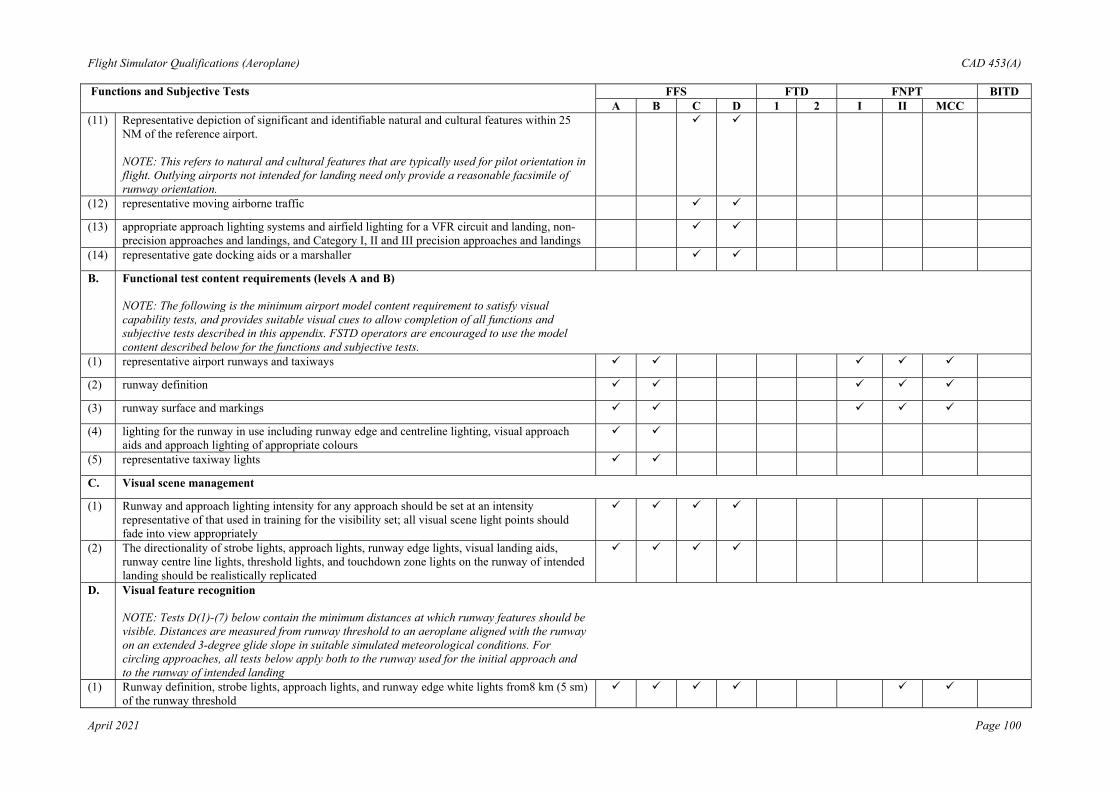
Flight Simulator Qualifications (Aeroplane) CAD 453(A)
April 2021 Page 100
Functions and Subjective Tests FFS FTD FNPT BITD A B C D 1 2 I II MCC (11) Representative depiction of significant and identifiable natural and cultural features within 25
NM of the reference airport. NOTE: This refers to natural and cultural features that are typically used for pilot orientation in flight. Outlying airports not intended for landing need only provide a reasonable facsimile of runway orientation.
(12) representative moving airborne traffic
(13) appropriate approach lighting systems and airfield lighting for a VFR circuit and landing, non-precision approaches and landings, and Category I, II and III precision approaches and landings
(14) representative gate docking aids or a marshaller
B. Functional test content requirements (levels A and B) NOTE: The following is the minimum airport model content requirement to satisfy visual capability tests, and provides suitable visual cues to allow completion of all functions and subjective tests described in this appendix. FSTD operators are encouraged to use the model content described below for the functions and subjective tests.
(1) representative airport runways and taxiways
(2) runway definition
(3) runway surface and markings
(4) lighting for the runway in use including runway edge and centreline lighting, visual approach aids and approach lighting of appropriate colours
(5) representative taxiway lights
C. Visual scene management
(1) Runway and approach lighting intensity for any approach should be set at an intensity representative of that used in training for the visibility set; all visual scene light points should fade into view appropriately
(2) The directionality of strobe lights, approach lights, runway edge lights, visual landing aids, runway centre line lights, threshold lights, and touchdown zone lights on the runway of intended landing should be realistically replicated
D. Visual feature recognition NOTE: Tests D(1)-(7) below contain the minimum distances at which runway features should be visible. Distances are measured from runway threshold to an aeroplane aligned with the runway on an extended 3-degree glide slope in suitable simulated meteorological conditions. For circling approaches, all tests below apply both to the runway used for the initial approach and to the runway of intended landing
(1) Runway definition, strobe lights, approach lights, and runway edge white lights from8 km (5 sm) of the runway threshold

Flight Simulator Qualifications (Aeroplane) CAD 453(A)
April 2021 Page 101
Functions and Subjective Tests FFS FTD FNPT BITD A B C D 1 2 I II MCC (2) Visual approach aids lights from 8 km (5 sm) of the runway threshold
(3) Visual approach aids lights from 5 km (3 sm) of the runway threshold
(4) Runway centreline lights and taxiway definition from 5 km (3 sm)
(5) Threshold lights and touchdown zone lights from 3 km (2 sm)
(6) Runway markings within range of landing lights for night scenes as required by the surface resolution test on day scenes
(7) For circling approaches, the runway of intended landing and associated lighting should fade into view in a non-distracting manner
E. Airport model content (Minimum of three specific airport scenes as defined below)
(1) Terminal Approach Area
(a) accurate portrayal of airport features is to be consistent with published data used for aeroplane operations
(b) all depicted lights should be checked for appropriate colours, directionality, behaviour and spacing (e.g., obstruction lights, edge lights, centre line, touchdown zone, VASI, PAPI, REIL and strobes)
(c) depicted airport lighting should be selectable via controls at the instructor station as required for aeroplane operation
(d) selectable airport visual scene capability at each model demonstrated for: (i) night (ii) twilight (iii) day
(e) (i) ramps and terminal buildings which correspond to an operator’s LOFT and LOS scenarios
(ii) terrain- appropriate terrain, geographic and cultural features
(iii) dynamic effects - the capability to present multiple ground and air hazards such as another aeroplane crossing the active runway or converging airborne traffic; hazards should be selectable via controls at the instructor station
(iv) illusions - operational visual scenes which portray representative physical relationships known to cause landing illusions, for example short runways, landing approaches over water, uphill or downhill runways, rising terrain on the approach path and unique topographic features Note: Illusions may be demonstrated at a generic airport or specific aerodrome.
F. Correlation with aeroplane and associated equipment
(1) visual system compatibility with aerodynamic programming
(2) visual cues to assess sink rate and depth perception during landings. Visual cueing sufficient to support changes in approach path by using runway perspective. Changes in visual cues during take-off and approach should not distract the pilot

Flight Simulator Qualifications (Aeroplane) CAD 453(A)
April 2021 Page 102
Functions and Subjective Tests FFS FTD FNPT BITD A B C D 1 2 I II MCC (3) accurate portrayal of environment relating to FSTD attitudes
(4) the visual scene should correlate with integrated aeroplane systems, where fitted (e.g. terrain, traffic and weather avoidance systems and head-up guidance system (HGS))
(5) representative visual effects for each visible, ownship, aeroplane external light
(6) The effect of rain removal devices should be. provided
G. Scene quality
(1) surfaces and textural cues should be free from apparent quantisation (aliasing)
(2) system capable of portraying full colour realistic textural cues
(3) the system light points should be free from distracting jitter, smearing or streaking
(4) demonstration of occulting through each channel of the system in an operational scene
(5) demonstration of a minimum of 10 levels of occulting through each channel of the system in an operational scene
(6) system capable of providing focus effects that simulate rain and light point perspective growth
(7) system capable of six discrete light step controls (0-5)
H. Environmental effects
(1) the displayed scene should correspond to the appropriate surface contaminants and include runway lighting reflections for wet, partially obscured lights for snow, or suitable alternative effects
(2) Special weather representations which include the sound, motion and visual effects of light, medium and heavy precipitation near a thunderstorm on take-off, approach and landings at and below an altitude of 600 m (2 000 ft) above the aerodrome surface and within a radius of 16 km (10 sm) from the aerodrome
(3) in-cloud effects such as variable cloud density, speed cues and ambient changes should be provided
(4) the effect of multiple cloud layers representing few, scattered, broken and overcast conditions giving partial or complete obstruction of the ground scene
(5) gradual break-out to ambient visibility/RVR, defined as up to 10% of the respective cloud base or top, 20 ft ≤ transition layer ≤200 ft; cloud effects should be checked at and below a height of 600 m (2 000 ft) above the aerodrome and within a radius of 16 km (10 sm) from the airport
(6) visibility and RVR measured in terms of distance. Visibility/RVR should be checked at and below a height of 600 m (2 000 ft) above the aerodrome and within a radius of 16 km (10 sm) from the airport
(7) patchy fog giving the effect of variable RVR. Note – Patchy fog is sometimes referred to as patchy RVR.
(8) effects of fog on aerodrome lighting such as halos and defocus

Flight Simulator Qualifications (Aeroplane) CAD 453(A)
April 2021 Page 103
Functions and Subjective Tests FFS FTD FNPT BITD A B C D 1 2 I II MCC (9) effect of ownship lighting in reduced visibility, such as reflected glare, to include landing lights,
strobes, and beacons
(10) wind cues to provide the effect of blowing snow or sand across a dry runway or taxiway should be selectable from the instructor station
I. Instructor controls of:
(1) Environmental effects, e.g. cloud base, cloud effects, cloud density, visibility in kilometres / statute miles and RVR in metres or feet
(2) Airport/aerodrome selection
(3) Airport/aerodrome lighting including variable intensity where appropriate (4)
(4)
(4) Dynamic effects including ground and flight traffic
J. Night visual scene capability
K. Twilight visual scene capability
L. Daylight visual scene capability
13. MOTION EFFECTS
The following specific motion effects are required to indicate the threshold at which a flight crew member should recognise an event or situation. Where applicable below, FFS pitch, side loading and directional control characteristics should be representative of the aeroplane as a function of aeroplane type:
A. Effects of runway rumble, oleo deflections, ground speed, uneven runway, runway centreline lights and taxiway characteristics
(1) After the aeroplane has been pre-set to the take-off position and then released, taxi at various speeds, first with a smooth runway, and note the general characteristics of the simulated runway rumble effects of oleo deflections. Next repeat the manoeuvre with a runway roughness of 50%, then finally with maximum roughness. The associated motion vibrations should be affected by ground speed and runway roughness. If time permits, different gross weights can also be selected as this may also affect the associated vibrations depending on aeroplane type. The associated motion effects for the above tests should also include an assessment of the effects of centreline lights, surface discontinuities of uneven runways, and various taxiway characteristics.
*(5)
B. Buffets on the ground due to spoiler/speedbrake extension and thrust
(1) Perform a normal landing and use ground spoilers and reverse thrust – either individually or in combination with each other – to decelerate the simulated aeroplane. Do not use wheel braking so that only the buffet due to the ground spoilers and thrust reversers is felt.
*(5)
C. Bumps associated with the landing gear
(1) Perform a normal take-off paying special attention to the bumps that could be perceptible due to maximum oleo extension after lift-off. When the landing gear is extended or retracted, motion bumps could be felt when the gear locks into position
*(5)

Flight Simulator Qualifications (Aeroplane) CAD 453(A)
April 2021 Page 104
Functions and Subjective Tests FFS FTD FNPT BITD A B C D 1 2 I II MCC D. Buffet during extension and retraction of landing gear
(1) Operate the landing gear. Check that the motion cues of the buffet experienced are reasonably representative of the actual aeroplane
*(5)
E. Buffet in the air due to flap and spoiler/speed brake extension
(1) First perform an approach and extend the flaps and slats, especially with airspeeds deliberately in excess of the normal approach speeds. In cruise configuration, verify the buffets associated with the spoiler/speed brake extension. The above effects could also be verified with different combinations of speed brake/flap/gear settings to assess the interaction effects.
*(5)
F. Approach-to-stall buffet and stall buffet (where applicable)
(1) Conduct an approach-to-stall with engines at idle and a deceleration of 1 kt/s. Check that the motion cues of the buffet, including the level of buffet increase with decreasing speed, are reasonably representative of the actual aeroplane.
Note: For FSTDs that are to be qualified for full stall training tasks (Level C or Level D), modelling that accounts for any increase in buffet amplitude from the initial buffet threshold of perception to the critical angle of attack or deterrent buffet as a function of the angle of attack; the stall buffet modelling should include effects of Nz, as well as Nx and Ny, if relevant.
G. Touchdown cues for main and nose gear
(1) Fly several normal approaches with various rates of descent. Check that the motion cues of the touchdown bump for each descent rate are reasonably representative of the actual aeroplane
*(5)
H. Nose wheel scuffing
(1) Taxi the simulated aeroplane at various ground speeds and manipulate the nose wheel steering to cause yaw rates to develop which cause the nose wheel to vibrate against the ground (“scuffing”). Evaluate the speed/nose wheel combination needed to produce scuffing and check that the resultant vibrations are reasonably representative of the actual aeroplane
*(5)
I. Thrust effect with brakes set
(1) With the simulated aeroplane set with the brakes on at the take-off point, increase the engine power until buffet is experienced and evaluate its characteristics. This effect is most discernible with wing mounted engines. Confirm that the buffet increases appropriately with increasing engine thrust
*(5)
J. Mach and manoeuvre buffet
(1) With the simulated aeroplane trimmed in 1 g flight while at high altitude, increase the engine power such that the Mach number exceeds the documented value at which Mach buffet is experienced. Check that the buffet begins at the same Mach number as it does in the aeroplane (for the same configuration) and that buffet levels are a reasonable representation of the actual aeroplane. In the case of some aeroplanes, manoeuvre buffet could also be verified for the same effects. Manoeuvre buffet can occur during turning flight at conditions greater than 1 g, particularly at higher altitudes
*(5)

Flight Simulator Qualifications (Aeroplane) CAD 453(A)
April 2021 Page 105
Functions and Subjective Tests FFS FTD FNPT BITD A B C D 1 2 I II MCC K. Tyre failure dynamics
(1) Dependent on aeroplane type, a single tyre failure may not necessarily be noticed by the pilot and therefore there should not be any special motion effect. There may possibly be some sound and/or vibration associated with the actual tyre losing pressure. With a multiple tyre failure selected on the same side the pilot may notice some yawing which should require the use of the rudder to maintain control of the aeroplane
L. Engine malfunction and engine damage
(1) The characteristics of an engine malfunction as stipulated in the malfunction definition document for the particular FSTD should describe the special motion effects felt by the pilot. The associated engine instruments should also vary according to the nature of the malfunction.
*(5)
M. Tail strikes and pod strikes
(1) Tail-strikes can be checked by over-rotation of the aeroplane at a speed below Vr whilst performing a take-off. The effects can also be verified during a landing. The motion effect should be felt as a noticeable bump. If the tail strike affects the aeroplane’s angular rates, the cueing provided by the motion system should have an associated effect.
*(5)
(2) Excessive banking of the aeroplane during its take-off/landing roll can cause a pod strike. The motion effect should be felt as a noticeable bump. If the pod strike affects the aeroplane’s angular rates, the cueing provided by the motion system should have an associated effect
*(5)
14. SOUND SYSTEM
A. The following checks should be performed during a normal flight profile with motion.
(1) precipitation
(2) rain removal equipment
(3) significant aeroplane noises perceptible to the pilot during normal operations, such as engine, flaps, gear, spoiler extension/retraction, thrust reverser to a comparable level of that found in the aeroplane
(4) abnormal operations for which there are associated sound cues including, but not limited to, engine malfunctions, landing gear/tire malfunctions, tail and engine pod strike and pressurisation malfunction
(5) sound of a crash when the FFS is landed in excess of limitations
(6) significant engine/propeller noise perceptible to pilot during normal operations

Flight Simulator Qualifications (Aeroplane) CAD 453(A)
April 2021 Page 106
Functions and Subjective Tests FFS FTD FNPT BITD A B C D 1 2 I II MCC 15. SPECIAL EFFECTS
A. Braking Dynamics
(1) Representative brake failure dynamics (including antiskid) and decreased brake efficiency due to high brake temperatures based on aeroplane related data. These representations should be realistic enough to cause pilot identification of the problem and implementation of appropriate procedures. FSTD pitch, side-loading and directional control characteristics should be representative of the aeroplane
B. Effects of Airframe and Engine Icing
Required only for those aeroplanes authorised for operations in known icing conditions. With the FSTD airborne, autopilot on and auto-throttles off, engine and aerofoil anti-ice/de-ice systems deactivated; activate icing conditions at a rate that allows monitoring of the FSTD and systems’ response. Icing recognition typically includes airspeed decay, change in FSTD pitch attitude, change in engine performance indications (other than due to airspeed changes), and change in data from the pitot/static system. Activate heating, anti-ice, or de-ice systems independently. Recognition includes proper effects of these systems, eventually returning the simulated aeroplane to normal flight.
Important Notes for Using the Table: (1) take-off characteristics sufficient to commence the airborne exercises; (2) for FNPT 1 and BITD only if multi-engine; (3) only trim change is required; (4) for FNPT, variable intensity airport lighting is not required; (5) An asterisk (*) denotes that the appropriate effect is required to be present for Level A FSTDs; and (6) Motion and buffet cues will only be applicable to FSTD equipped with an appropriate motion system.

Flight Simulator Qualifications (Aeroplane) CAD 453(A)
April 2021 Page 107
CHAPTER 7 LEVEL 'A' FLIGHT SIMULATORS 1. Background 1.1 When determining the cost effectiveness of any flight simulator many factors should be
taken into account such as environmental, safety, accuracy, repeatability, quality and depth of training, weather and crowded airspace.
1.2 Although CAD 453(A) recognizes the criteria for Level 'A' Simulators, the requirements
for the lowest level of flight simulator do not appear to have been promoting the anticipated interest in the acquisition of lower-cost flight simulators for the smaller aircraft used by the general aviation community.
1.3 The significant cost drivers associated with the production of any simulator are:
1.3.1 type-specific data package;
1.3.2 QTG flight test data;
1.3.3 motion system;
1.3.4 visual system;
1.3.5 flight controls; and
1.3.6 aircraft parts.
NOTE: To attempt to reduce the cost of ownership of a CAD Level-A FFS, each element
has been examined in turn and with a view to relaxing the requirements where possible whilst recognizing the training, checking and testing credits allowed on such a device.
2. Data Package
2.1 The cost of collecting specific flight test data sufficient to provide a complete model of the
aerodynamics, engines and flight controls can be significant. The use of a class specific data package which could be tailored to represent a specific type of aeroplane is encouraged. This may enable a well-engineered light-twin baseline data package to be carefully tuned to adequately represent any one of a range of similar aeroplanes. Such work including justification and the rationale for the changes would have to be carefully documented and available for consideration by the Department as part of the qualification process. Note that for this lower level of FFS, the use of generic ground handling and generic ground effect models is allowed.
2.2 However specific flight test data to meet the needs of each relevant test within the QTG will be required. Recognizing the cost of gathering such data, the following points should be borne in mind:
2.2.1 For this class of simulator, much of the flight test information could be gathered
by simple means e.g. stopwatch, pencil and paper or video. However comprehensive details of test methods and initial conditions should be presented.
2.2.2 A number of tests within the QTG have had their tolerances reduced to 'Correct Trend and Magnitude' (CT&M) thereby avoiding the need for specific flight test data.

Flight Simulator Qualifications (Aeroplane) CAD 453(A)
April 2021 Page 108
2.2.3 The use of CT&M is not to be taken as an indication that certain areas of simulation can be ignored. Indeed in the class of aeroplane envisaged, that might take advantage of Level A, it is imperative that the specific characteristics are present, and incorrect effects would be unacceptable (e.g. if the aeroplane has a weak positive spiral stability, it would not be acceptable for the FFS to exhibit neutral or negative spiral stability).
2.2.4 Where CT&M is used as a tolerance, it is strongly recommended that an
automatic recording system be used to 'footprint' the baseline results thereby avoiding the effects of possible divergent subjective opinions on recurrent evaluations.
3. Motion
3.1 For Level-A FFS, the requirements for both the primary cueing and buffet simulation have
been not specified in detail. Traditionally, for primary cueing, emphasis has been laid on the numbers of axes available on the motion system. For this level of FFS, the FFS manufacturer should be allowed to decide on the complexity of the motion system. However, during the evaluation, the motion system will be assessed subjectively to ensure that it is supporting the piloting task, including engine failures, and never provides negative cueing.
3.2 Buffet simulation is important to add realism to the overall simulation; for Level A, the effects can be simple but they should be appropriate, in harmony with the sound cues and never provide negative training.
4. Visual
4.1 Other than field of view (FOV), specific technical criteria for the visual systems are not
specified. The emergence of lower cost 'raster only' daylight systems is recognised. The adequacy of the performance of the visual system will be determined by its ability to support the flying tasks. e.g. 'Visual cueing sufficient to support changes in approach path by using runway perspective'.
4.2 The collimated visual optics may not always be needed. A single channel direct viewing system would be acceptable for an FFS of a single crew aeroplane. (The risk here is that, should the aeroplane be subsequently upgraded to multi-crew, the non-collimated visual system may be unacceptable.)
4.3 The vertical FOV specified (30) may be insufficient for certain tasks. Some smaller
aircraft have large downward viewing angles which cannot be accommodated by the +/–15 vertical FOV. This can lead to two limitations:
4.3.1 at the CAT I All Weather Operations decision height, the appropriate visual
ground segment may not be seen; and
4.3.2 uring an approach, where the aeroplane goes below the ideal approach path, during the subsequent pitch-up to recover, adequate visual reference to make a landing on the runway may be lost.
5. Flight Controls
5.1 The specific requirements for flight controls remain unchanged. Because the handling
qualities of smaller aeroplanes are inextricably intertwined with their flight controls, there is little scope for relaxation of the tests and tolerances. It could be argued that with reversible control systems the on ground static sweep should in fact be replaced by more

Flight Simulator Qualifications (Aeroplane) CAD 453(A)
April 2021 Page 109
representative 'in air' testing. It is hoped that lower cost control loading systems would be adequate to fulfil the needs of this level of simulation (i.e. electric).
6. Aircraft Parts
6.1 As with any level of FSTD, the components used within the cockpit area need not be
aircraft parts; however, any parts used should be robust enough to ensure the training tasks. Moreover, the Level A FFS is type specific, thus all relevant switches, instruments, controls etc. within the simulated area will be required to look and feel 'as aeroplane'.

Flight Simulator Qualifications (Aeroplane) CAD 453(A)
April 2021 Page 110
CHAPTER 8 FLIGHT SIMULATORS APPROVED OR QUALIFIED UNDER PREVIOUS REGULATIONS
1. Introduction
1.1 Under previous regulations, flight simulators may have gained credits in accordance with
primary reference documents which state appropriate technical criteria.
1.2 Other flight simulators may not have been monitored to the same extent, but may have documents or statements from the Department giving broad or specific permission for them to be used for certain training, testing and checking maneuvers.
1.3 In any case, it is intended that flight simulators should continue to maintain their
qualification level and/or approval granted prior to the publication of CAD 453(A). 2. Re-categorisation
2.1 Some of these flight simulators may be of a standard which permits them to be re-
categorised as if they were simulators presented for initial qualification under CAD 453(A). 3. Equivalent Categories AG, BG, CG, DG
3.1 Flight simulators that are not re-categorised but which have an acceptable primary
reference document used for their original qualification or approval, will gain a CAD qualification based upon their original technical qualification level or credits. The equivalent qualification will relate to permitted maneuvers in the original Qualification/Approval document providing that these older flight simulators continue to meet the original criteria when evaluated by the Department.
3.2 The following table describes the relationship:
CAD QUALIFICATION LEVEL Flight Simulators Qualified Under Previous Regulations
CAD QUALIFICATION LEVEL Flight Simulators Qualified Under CAD 453
AG Similar maximum credits for A
BG Similar maximum credits for B
CG Similar maximum credits for C
DG Similar maximum credits for D
NOTE: To comply with the rule, the primary reference document should have meaningful
validation, Functions and Subjective Tests criteria which reasonably cover the performance envelope of the simulator and in particular the maneuvers for which the equivalent CAD qualification level is given. The minimum acceptable standard is JAR-STD 1A Issued 30 April 1997, FAA AC 120(4)0B, ICAO 9625 First Edition, International Standards For The Qualification of Airplane Flight Simulators (January 1992)or equivalent.
4. Original Qualification
4.1 Flight Simulators that are not re-categorised and that do not have an acceptable primary
reference document may continue to enjoy credits for an agreed list of training, testing and checking maneuvers, provided they maintain their performance in accordance with any validation, Functions and Subjective Tests which have been previously established or a list of tests selected from CAD 453(A) by agreement with the Department. Again the test

Flight Simulator Qualifications (Aeroplane) CAD 453(A)
April 2021 Page 111
should relate to the list of maneuvers permitted under the original Qualification/Approval document.
4.2 The award of credits to a flight simulator user should be at the discretion of the Department. Current users may retain the credits granted under their previous criteria.
5. Grandfather Rights Summary
5.1 The following Table summarizes the arrangements for simulators approved or qualified
under previous regulations and which are not re-categorised:
CAD EQUIVALENT QUALIFICATION LEVEL
PERFORMANCE CRITERIA
Primary Reference Document
AG BG CG DG
Maximum training, testing and checking Credits similar to A, B, C, D
Performance to the original National Validation Functions and Subjective Tests from Reference Doc.
No Primary Reference Document
Special Categories Unique list of Maneuvers
Original Validation, Functions and Subjective Tests or a list of tests selected from CAD 453(A).
NOTE: In all cases, final approval is by CAD assessment of individual applications.

Flight Simulator Qualifications (Aeroplane) CAD 453(A)
April 2021 Page 112
CHAPTER 9 NEW AIRCRAFT PROGRAMMES 1. New Aeroplane Simulator Qualification
1.1 During the introduction of new aeroplane programs, it is not always possible to obtain all
the necessary data and certified aeroplane avionics in time to satisfy the requirements for normal simulator qualification. The Department may accept a measure of engineering and predicted data as well as preliminary avionics for a limited period to enable crew training to begin without delay.
1.2 Simulator operators seeking interim qualification should contact the Department at the earliest opportunity.
2. New Aeroplane Simulator Qualification – Additional Information
2.1 It is usual that aeroplane manufacturer's approved final data for performance, handling ms
or avionics will not be available until well after a new or derivative aircraft has entered service. It is often necessary to begin flight crew training and certification several months prior to the entry of the first aeroplane into service and consequently it may be necessary to use aeroplane manufacturer provided preliminary data for interim qualification of flight simulators.
2.2 In recognition of the sequence of events that should occur and the time required for final
data to become available, the Department may accept certain partially validated preliminary aeroplane and systems data, and early release ('red label') avionics in order to permit the necessary programme schedule for training, certification and service introduction.
2.3 Operators seeking qualification based on preliminary data should, however, consult the Department as soon as it is known that special arrangements will be necessary or as soon as it is clear that the preliminary data will need to be used for simulator qualification. The aeroplane and simulator manufacturers should also be made aware of the requirements and agree to the data plan and simulator qualification plan. The plan should include periodic meetings to keep the interested parties informed of project status.
2.4 The precise procedure followed to gain Department acceptance of preliminary data will vary from case to case and between aeroplane manufacturers. Each aeroplane manufacturer's new aeroplane development and test programme is designed to suit the needs of the particular project and may not contain the same events or sequence of events as another manufacturer's programme or even the same manufacturer's programme for a different aeroplane. Hence, there cannot be a prescribed invariable procedure for acceptance of preliminary data, but instead a statement of needs with the final sequence of events, data sources, and validation procedures agreed by the operator, the aeroplane manufacturer, the simulator manufacturer, and the Department.
NOTE: A description of aeroplane manufacturer provided data needed for simulator
modelling and validation is to be found in the IATA Document 'Flight Simulator Design and Performance Data Requirements' edition 6 2000 or as amended), or in the ARINC Specification 450 Document 'Flight Simulator Design and Performance Data Requirements' published on December 2, 2016 or as amended .
2.5 There should be assurance that the preliminary data is the manufacturer's best
representation of the aeroplane and reasonable certainty that final data will not deviate to a large degree from these preliminary, but refined, estimates. Data derived from these predictive or preliminary techniques should be validated by available sources including, at least, the following:

Flight Simulator Qualifications (Aeroplane) CAD 453(A)
April 2021 Page 113
2.5.1 a manufacturer's engineering report explaining the predictive method used and
illustrating past success of the method on similar projects. For example, the manufacturer could show the application of the method to an earlier aeroplane model or predict the characteristics of an earlier model and compare the results to final data for that model; and
2.5.2 early flight test data will often be derived from aeroplane certification tests, and should be used to maximum advantage for early simulator validation. Certain critical tests, which would normally be done early in the aeroplane certification programme, should be included to validate essential pilot training and certification manoeuvres. These include cases in which a pilot is expected to cope with an aeroplane failure mode including engine failures. The early data available will, however, depend on the aeroplane manufacturer's flight test programme design and may not be the same in each case. It is expected that the flight test programme of the aeroplane manufacturer will include provisions for generation of very early flight tests results for simulator validation.
2.6 The use of preliminary data is not indefinite. The aeroplane manufacturer's final data
should be available within six months after aeroplane first 'service entry' or as agreed by the Department, the operator and the aeroplane manufacturer, but usually not later than one year. In applying for an interim qualification, using preliminary data, the Operator and the Department should agree the update programme. This will normally specify that the final data update will be installed in the simulator within a period of six months following the final data release unless special conditions exist and a different schedule agreed. The simulator performance and handling validation would then be based on data derived from flight test. Initial aeroplane systems data should be updated after engineering tests. Final aeroplane systems data should also be used for simulator programming and validation.
2.7 Flight simulator avionics should stay essentially in step with aeroplane avionics (hardware & software) updates. The permitted time lapse between aeroplane and flight simulator updates is not a fixed time but should be minimal. It may depend on the magnitude of the update and whether the QTG and pilot training and checking are affected. Permitted differences in aeroplane and simulator avionics versions and the resulting effects on simulator qualification should be agreed between the operator and the Department. Consultation with the flight simulator manufacturer is desirable throughout the agreement of the qualification process.
2.8 The following describes an example of the design data and sources which might be used in
the development of an interim qualification plan:
2.8.1 the plan should consist of the development of a QTG based upon a mix of flight test and engineering simulation data. For data collected from specific aeroplane flight tests, or other flights, the required designed model/data changes necessary to support an acceptable *Proof of Match (POM) should be generated by the aeroplane manufacturer; and
2.8.2 in order to ensure that the two sets of data are properly validated, the aeroplane manufacturer should compare their simulation model responses against the flight test data, when driven by the same control inputs and subjected to the same atmospheric conditions as were recorded in the flight test. The model responses should result from a simulation where the following systems are run in an integrated fashion and are consistent with the design data released to the flight simulator manufacturer:
(a) Propulsion;

Flight Simulator Qualifications (Aeroplane) CAD 453(A)
April 2021 Page 114
(b) Aerodynamics;
(c) Mass Properties;
(d) Flight Controls;
(e) Stability Augmentation; and
(f) Brakes/Landing Gear.
2.9 For the qualification of flight simulators of new aeroplanes types, it may be beneficial that the services of a suitably qualified test pilot are used for the purpose of assessing handling qualities and performance evaluation.
NOTE: *The Proof of Match (POM) should meet the relevant CAD 453(A) tolerances.
Flight Simulator Qualifications (Aeroplane) CAD 453(A)
April 2021 Page 115
CHAPTER 10 QUALITY SYSTEM 1. Quality System
1.1 In order to demonstrate compliance with Chapter 2, para. 3.1, an operator of a flight
simulator should establish its quality system in accordance with the instruction and information contained in the following paragraphs.
2. General
2.1 Terminology
2.1.1 The terms used in the context of the requirement for an AOC’s quality system
have the following meaning: (a) Accountable Manager. The person acceptable to CAD who has corporate
authority for ensuring that all necessary activities can be financed and carried out to the standard required by CAD, and any additional requirements defined by the operator; and
(b) Quality Assurance. Quality assurance, as distinguished from quality control, involves activities in the business, systems, and technical audit areas. It is a set of predetermined, systemic actions which are required to provide adequate confidence that the performance, functions and characteristics satisfy given requirements.
2.2 Quality Control
2.2.1 An operator shall establish a formal, written quality policy statement that is a
commitment by the Accountable Manager as to what the quality system is intended to achieve. The quality policy should reflect the achievement and continued compliance with CAD 453(A) together with any additional standards specified by the operator.
2.2.2 The Accountable Manager is an essential part of the operator’s management organisation. It is usually the Chief Executive Officer, or equivalent, of the operator, who by virtue of his position has overall responsibility, including financial, for managing the organisation.
2.2.3 The Accountable Manager will have overall responsibility for the operator’s
quality system, including the frequency, format and structure of the internal management evaluation activities as prescribed in para. 4.10 below.
2.3 Purpose of The Quality System
2.3.1 The quality system should enable the operator to monitor compliance with CAD
453(A), and any other standards specified by the operator, or CAD, to ensure performance of the device.
2.4 Quality Manager
2.4.1 The function of the Quality Manager to monitor compliance with, and the
adequacy of, procedures required to ensure performance of the device as required by the regulations and requirements may be carried out by more than one person by means of different, but complementary, quality assurance programs.
Flight Simulator Qualifications (Aeroplane) CAD 453(A)
April 2021 Page 116
2.4.2 The primary role of the Quality Manager is to verify, by monitoring activity in the fields of simulator operation, that the standards required by CAD, and any additional requirements defined by the operator, are being carried out under the supervision of the manager.
2.4.3 The Quality Manager should be responsible for ensuring that the quality assurance
programme is properly established, implemented and maintained. 2.4.4 The Quality Manager should:
(a) report to the Accountable Manager; and
(b) have access to all parts of the simulator operator’s, and as necessary, any
sub-contractor’s organisation.
2.4.5 The posts of Accountable Manager and the Quality Manager may be combined by simulator operators whose structure and size may not justify the separation of those two posts. However, in this event, Quality Audits should be conducted by independent personnel.
3. Quality System Structure
3.1 Introduction
3.1.1 The operator’s quality system should ensure compliance with simulator
qualification requirements, standards, and operational procedures.
3.1.2 The operator should specify the basic structure of the quality system.
3.1.3 The quality system should be structured according to the size and complexity of the operation to be monitored.
3.2 Scope
3.2.1 As a minimum, the quality system should address the following:
(a) the provisions of CAD 453(A);
(b) the operator’s additional standards and operating practices;
(c) the operator’s quality policy;
(d) the operator’s organizational structure;
(e) responsibility for the development, establishment and management of the
quality system;
(f) documentation, including manuals, reports and records;
(g) quality procedures;
(h) quality assurance programme;
(i) the provision of adequate financial, material and human resources; and
(j) training requirements for the various functions in the organisation.

Flight Simulator Qualifications (Aeroplane) CAD 453(A)
April 2021 Page 117
3.2.2 The quality system should include a feedback system to the Accountable Manager to ensure that corrective actions are both identified and promptly addressed. The feedback system should also specify who is required to rectify discrepancies and non-compliance in each particular case, and the procedure to be followed if corrective action is not completed within an appropriate timescale.
3.3 Relevant Documentation
3.3.1 Relevant documentation includes the relevant part of the operator’s manual system.
3.3.2 In addition, relevant document should include the following:
(a) quality policy;
(b) terminology;
(c) reference to the specified simulator technical standards;
(d) a description of the organisation;
(e) the allocation of duties and responsibilities;
(f) qualification procedures to ensure regulatory compliance;
(g) the quality assurance programme, reflecting;
(h) schedule of the monitoring process;
(i) audit procedures;
(j) reporting procedures;
(k) follow-up and corrective action procedures;
(l) recording system;
(m) the training syllabus; and
(n) document control.
4. Quality Assurance Program
4.1 Introduction
4.1.1 The quality assurance programme should include all planned and systematic
actions necessary to provide confidence that all maintenance is conducted and performance maintained in accordance with all applicable requirements, standards and operational procedures.
4.1.2 When establishing a quality assurance programme, consideration should be given to at least the following:
(a) quality inspection; (b) audit;
(c) auditors;

Flight Simulator Qualifications (Aeroplane) CAD 453(A)
April 2021 Page 118
(d) auditor’s independence;
(e) audit scope;
(f) audit scheduling;
(g) monitoring and corrective action;
(h) management evaluation; and
(i) recording.
4.2 Quality Inspection
4.2.1 The primary purpose of a quality inspection is to observe a particular
event/action/document, etc. in order to verify whether established operational procedures and requirements are followed during the accomplishment of that event and whether the required standard is achieved.
4.2.2 Typical subject areas for quality inspections are:
(a) actual simulator operations;
(b) maintenance;
(c) technical standards; and
(d) flight simulator safety features. 4.3 Audit
4.3.1 An audit is a systematic and independent comparison of the way in which an
operation is being conducted against the way in which the published operational procedures say it should be conducted.
4.3.2 Audits should include at least the following quality procedures and processes:
(a) a statement explaining the scope of the audit; (b) planning and preparation; (c) gathering and recording evidence; and (d) analysis of the evidence.
4.3.3 Techniques that contribute to an effective audit are: (a) interviews or discussions with personnel;
(b) a review of published documents;
(c) the examination of an adequate sample of records;
(d) the witnessing of the activities that make up the operation; and
(e) The preservation of documents and the recording of observations.

Flight Simulator Qualifications (Aeroplane) CAD 453(A)
April 2021 Page 119
4.4 Auditors 4.4.1 An operator should decide, depending upon the complexity of the operations,
whether to make use of a dedicated audit team or a single auditor. In any event, the auditor or audit team should have relevant simulator experience.
4.4.2 The responsibilities of the auditors should be clearly defined in the relevant documentation.
4.5 Auditor’s Independence
4.5.1 Auditors should not have any day-to-day involvement in the area of the operation
activity that is to be audited. An operator may, in addition to using the services of full-time dedicated personnel belonging to a separate quality department, undertake the monitoring of specific areas or activities by the use of part-time auditors. An operator whose structure and size does not justify the establishment of full-time auditors, may undertake the audit function by the use of part-time personnel from within its own organisation or from an external source under the terms of an agreement acceptable to CAD. In all cases the operator should develop suitable procedures to ensure that persons directly responsible for the activities to be audited are not selected as part of the auditing team. Where external auditors are used, it is essential that any external specialist is familiar with the type of devices operated by the simulator operator.
4.5.2 The operator’s quality assurance programme should identify the persons within the company who have the experience, responsibility and authority to:
(a) perform quality inspections and audits as part of ongoing quality
assurance;
(b) identify and record any concerns or findings, and the evidence necessary to substantiate such concerns or findings;
(c) initiate or recommend solutions to concerns or findings through designated reporting channels;
(d) verify the implementation of solutions within specific timescales; and
(e) report directly to the Quality Manager.
4.6 Audit Scope 4.6.1 Operators are required to monitor compliance with the operational procedures they
have designed to ensure safe operations and the serviceability of both operational and safety equipment. In doing so they should as a minimum, and where appropriate, monitor:
(a) organisation;
(b) plans and company objectives;
(c) maintenance procedures;
(d) simulator qualification level;
(e) supervision;

Flight Simulator Qualifications (Aeroplane) CAD 453(A)
April 2021 Page 120
(f) simulator technical status;
(g) personnel training; and
(h) aeroplane modification management.
4.7 Audit Scheduling 4.7.1 A quality assurance programme should include a defined audit schedule and a
periodic review cycle area by area. The schedule should be flexible, and allow unscheduled audits when trends are identified. Follow-up audits should be scheduled when necessary to verify that corrective action was carried out and that it was effective.
4.7.2 An operator should establish a schedule of audits to be completed during a specified calendar period. All aspects of the operation should be reviewed within every 12 month period in accordance with the programme unless an extension to the audit period is accepted as explained below. An operator may increase the frequency of audits at its discretion but should not decrease the frequency without the agreement of CAD.
4.7.3 When an operator defines the audit schedule, significant changes to the
management, organisation, operation, or technologies should be considered as well as changes to the regulatory requirements.
4.8 Monitoring
4.8.1 The aim of monitoring within the quality system is primarily to investigate and
judge its effectiveness and thereby to ensure that defined policy, operational, and maintenance standards are continuously complied with. Monitoring activity is based upon quality inspections, audits, corrective action and follow-up. The operator should establish and publish a quality procedure to monitor regulatory compliance on a continuing basis. This monitoring activity should be aimed at eliminating the causes of unsatisfactory performance.
4.8.2 Any non-compliance identified as a result of monitoring should be communicated to the manager responsible for taking corrective action or, if appropriate, the Accountable Manager. Such non-compliance should be recorded, for the purpose of further investigation, in order to determine the cause and to enable the recommendation of appropriate corrective action.
4.9 Corrective Action
4.9.1 The quality assurance programme should include procedures to ensure that
corrective actions are taken in response to findings. These quality procedures should monitor such actions to verify their effectiveness and that they have been completed. Organizational responsibility and accountability for the implementation of corrective action resides with the department cited in the report identifying the finding. The Accountable Manager will have the ultimate responsibility for resourcing the corrective active action and ensuring, through the Quality Manager, that the corrective action has reestablished compliance with the standard required by CAD, and any additional requirements defined by the operator.
4.9.2 Subsequent to the quality inspection/audit, the operator should establish:
(a) the seriousness of any findings and any need for immediate corrective

Flight Simulator Qualifications (Aeroplane) CAD 453(A)
April 2021 Page 121
action;
(b) the cause of the finding;
(c) what corrective actions are required to ensure that the non-compliance does not recur;
(d) a schedule for corrective action;
(e) the identification of individuals or departments responsible for implementing corrective action; and
(f) allocation of resources by the accountable manager, where appropriate.
4.9.3 The Quality Manager should:
(a) verify that corrective action is taken by the manager responsible in response to any finding of non-compliance;
(b) verify the corrective action includes the elements outlined in para. 4.9;
(c) monitor the implementation and completion of corrective action;
(d) provide management with an independent assessment of corrective action; implementation and completion; and
(e) evaluate the effectiveness of corrective action through follow-up process.
4.10 Management Evaluation
4.10.1 A management evaluation is a comprehensive, systematic, documented review by
the management of the quality system, operational policies and procedures, and should consider: (a) the results of quality inspections, audits and any other indicators; and
(b) the overall effectiveness of the management organisation in achieving
stated objectives.
4.10.2 A management should identify and correct trends, and prevent, where possible, future non-conformities. Conclusions and recommendations made as a result of an evaluation should be submitted in writing to the responsible manager for action. The responsible manager should be an individual who has the authority to resolve issues and take action.
4.10.3 The Accountable Manager should decide upon the frequency, format and structure of internal management evaluation activities.
4.11 Recording
4.11.1 Accurate, complete and readily accessible records documenting the results of the
quality assurance programme should be maintained by the operator. Records are essential data to enable an operator to analyze and determine the root causes of non-conformity, so that areas of non-compliance can be identified and addressed.
4.11.2 The following records should be retained for a period of 5 years:

Flight Simulator Qualifications (Aeroplane) CAD 453(A)
April 2021 Page 122
(a) audit schedules;
(b) quality inspection and audit reports;
(c) responses to findings;
(d) corrective action reports;
(e) follow-up and closure reports; and
(f) management evaluation reports.
5. Quality Assurance Responsibility for Sub-contractors
5.1 Operators may decide to sub-contract out certain activities to external agencies for the provision of services related to areas such as: 5.1.1 maintenance; and
5.1.2 manual preparation.
5.2 The ultimate responsibility for the product or service provided by the sub-contractor always
remains with the operator. A written agreement should exist between the operator and the sub-contractor clearly defining the safety related services and quality to be provided. The sub-contractor’s safety related activities relevant to the agreement should be included in the operator’s quality assurance programme.
5.3 The operator should ensure that the sub-contractor has the necessary authorisation/approval when required and commands the resources and competence to undertake the task.
6. Quality System Training
6.1 General
6.1.1 An operator should establish effective, well planned and resourced quality related
briefing for all personnel.
6.1.2 Those responsible for managing the quality system should receive training covering:
(a) an introduction to the concept of the quality system;
(b) quality management;
(c) the concept of quality assurance;
(d) quality manuals;
(e) audit techniques;
(f) reporting and recording; and
(g) the way in which the quality system will function in the company.
6.1.3 Time should be provided to train every individual involved in quality management
and for briefing the remainder of the employees. The allocation of time and resources should be sufficient for the scope of the training.

Flight Simulator Qualifications (Aeroplane) CAD 453(A)
April 2021 Page 123
6.2 Sources of Training
6.2.1 Quality management courses are available from the various organisations and
International Standards Institutions, and an operator should consider whether to offer such courses to those likely to be involved in the management of quality systems. Operators with sufficient appropriately qualified staff should consider whether to carry out in-house training.
7. Standard Measurements for Flight Simulator Quality
7.1 It is recognised that a Quality System tied to measurement of simulator performance will probably lead to improving and maintaining training quality. One acceptable means of measuring simulator performance is as defined and agreed by industry in ARINC report 433 (April 5, 2013 or as amended) entitled “Standard Measurements for Flight Simulator Quality”.

Flight Simulator Qualifications (Aeroplane) CAD 453(A)
April 2021 Page 124
APPENDUM I. Suggested reference sources to be read in conjunction with CAD 453(A) are listed below:
(i) ICAO Doc 9625 – Manual of Criteria for the Qualification of Flight Simulation Training Devices”
(ii) EASA Certification Specifications for Aeroplane Flight Simlation Training Devices
(CS-FSTD(A)) (iii) FAA Regulations 14 CFR Part 60 – Flight Simulation Training Device Initial and
Continuing Qualification and Use (iv) Transport Canada TP 9685 – Aeroplane and Rotorcraft Simulator Manual (v) Royal Aeronautical Society Publication Aeroplane Flight Simulation Training
Device (FSTD) Evaluation Handbook (vi) International Standards for the Qualification of Airplane Flight Simulators.
Note: The above listed reference sources above are not to be considered as exclusive nor exhaustive.
The latest versions/issues of these documents shall be consulted.
*******