Embed Size (px)
Citation preview
Honors engineering Statics – MECH 223h
Review Problems for Midterm 1
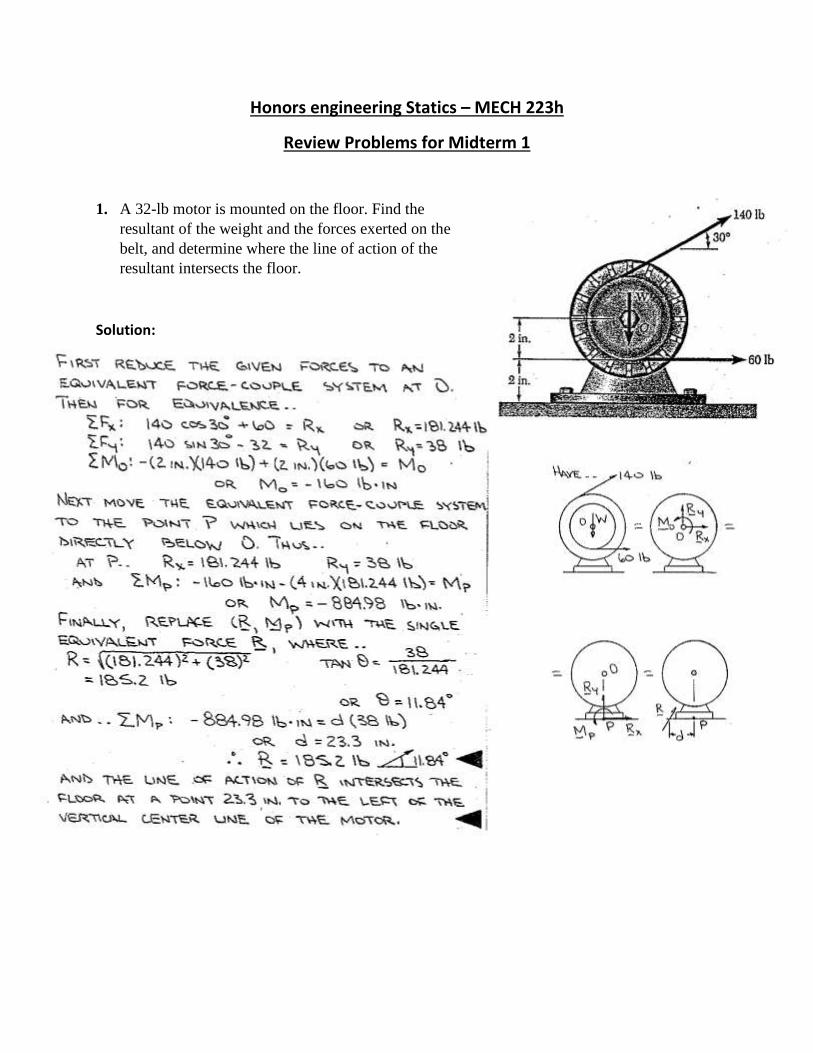
1. A 32-lb motor is mounted on the floor. Find the
resultant of the weight and the forces exerted on the
belt, and determine where the line of action of the
resultant intersects the floor.
Solution:
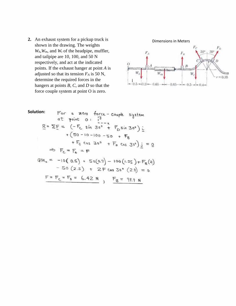
2. An exhaust system for a pickup truck is
shown in the drawing. The weights
Wh,Wm, and Wt of the headpipe, muffler,
and tailpipe are 10, 100, and 50 N
respectively, and act at the indicated
points. If the exhaust hanger at point A is
adjusted so that its tension FA is 50 N,
determine the required forces in the
hangers at points B, C, and D so that the
force couple system at point O is zero.
Solution:
Dimensions in Meters
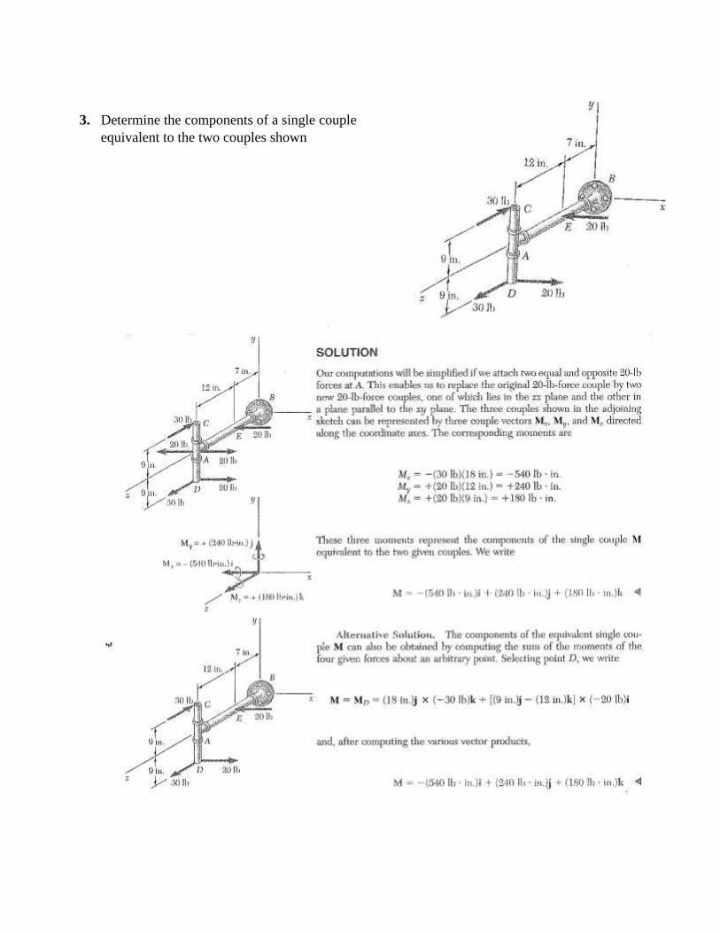
3. Determine the components of a single couple
equivalent to the two couples shown
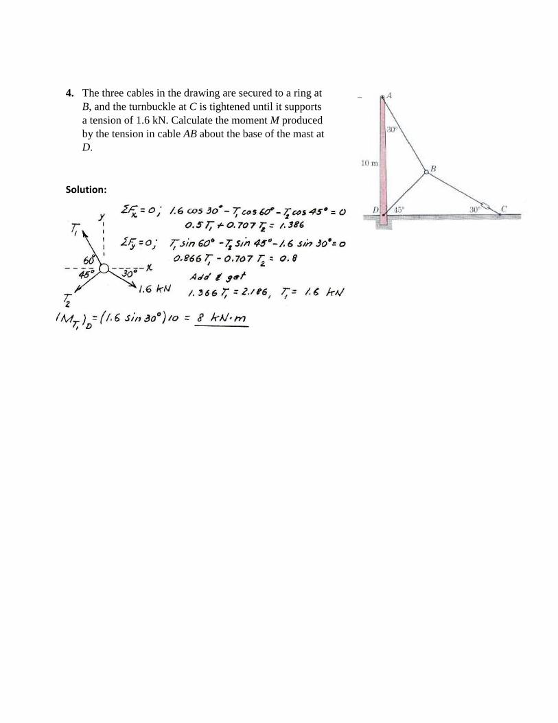
4. The three cables in the drawing are secured to a ring at
B, and the turnbuckle at C is tightened until it supports
a tension of 1.6 kN. Calculate the moment M produced
by the tension in cable AB about the base of the mast at
D.
Solution:
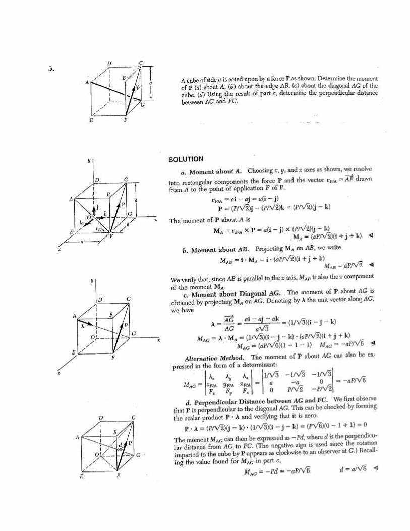
5.
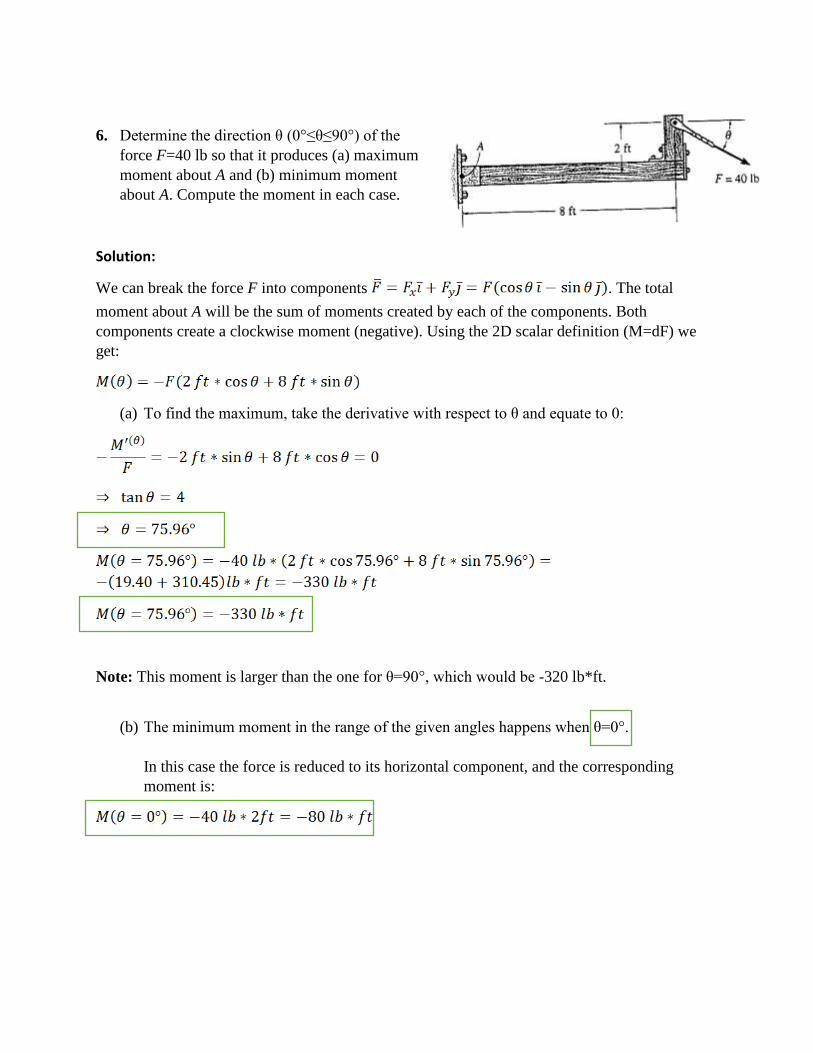
6. Determine the direction θ (0°≤θ≤90°) of the
force F=40 lb so that it produces (a) maximum
moment about A and (b) minimum moment
about A. Compute the moment in each case.
Solution:
We can break the force F into components . The total
moment about A will be the sum of moments created by each of the components. Both
components create a clockwise moment (negative). Using the 2D scalar definition (M=dF) we
get:
(a) To find the maximum, take the derivative with respect to θ and equate to 0:
Note: This moment is larger than the one for θ=90°, which would be -320 lb*ft.
(b) The minimum moment in the range of the given angles happens when θ=0°.
In this case the force is reduced to its horizontal component, and the corresponding
moment is:
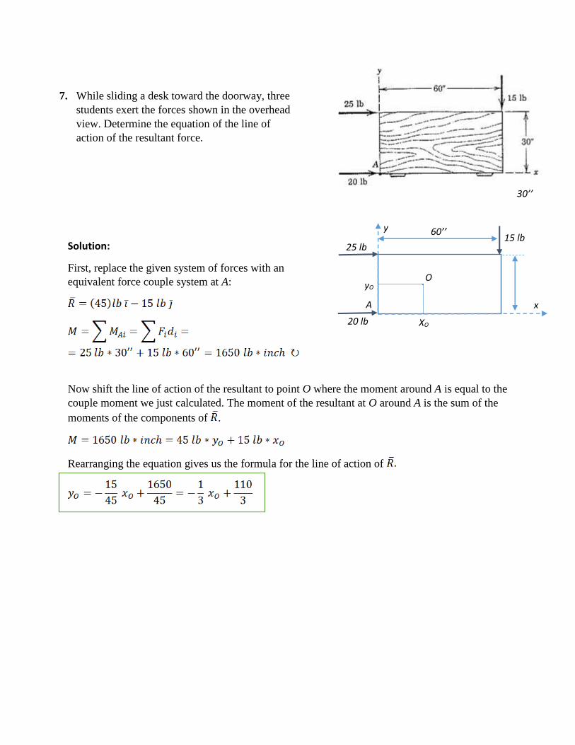
7. While sliding a desk toward the doorway, three
students exert the forces shown in the overhead
view. Determine the equation of the line of
action of the resultant force.
Solution:
First, replace the given system of forces with an
equivalent force couple system at A:
Now shift the line of action of the resultant to point O where the moment around A is equal to the
couple moment we just calculated. The moment of the resultant at O around A is the sum of the
moments of the components of .
Rearranging the equation gives us the formula for the line of action of
. O
x
y
A
XO
yO
20 lb
25 lb 15 lb
60’’
30’’
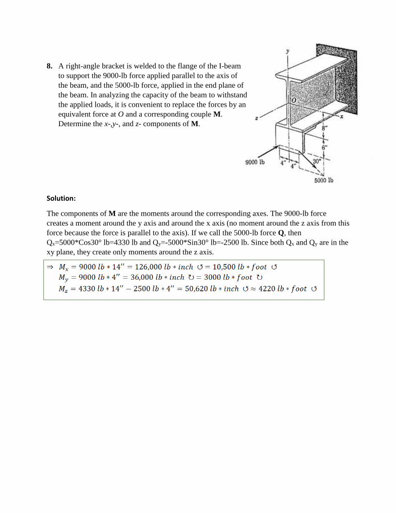
8. A right-angle bracket is welded to the flange of the I-beam
to support the 9000-lb force applied parallel to the axis of
the beam, and the 5000-lb force, applied in the end plane of
the beam. In analyzing the capacity of the beam to withstand
the applied loads, it is convenient to replace the forces by an
equivalent force at O and a corresponding couple M.
Determine the x-,y-, and z- components of M.
Solution:
The components of M are the moments around the corresponding axes. The 9000-lb force
creates a moment around the y axis and around the x axis (no moment around the z axis from this
force because the force is parallel to the axis). If we call the 5000-lb force Q, then
Qx=5000*Cos30° lb=4330 lb and Qy=-5000*Sin30° lb=-2500 lb. Since both Qx and Qy are in the
xy plane, they create only moments around the z axis.
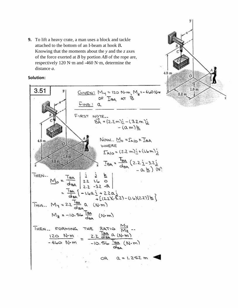
9. To lift a heavy crate, a man uses a block and tackle
attached to the bottom of an I-beam at hook B.
Knowing that the moments about the y and the z axes
of the force exerted at B by portion AB of the rope are,
respectively 120 N·m and -460 N·m, determine the
distance a.
Solution: