Embed Size (px)
Citation preview

HORIZONTAL DIRECTIONAL DRILL ANALYSIS CREEK ROAD/ CONODOGUINET CREEK CROSSING
PADEP SECTION 105 PERMIT NO.S: E21-449 PA-CU-0125.0000-WX & PA-CU-0125.0000-WX-16
(SPLP HDD No. S2-0181)
CREEK ROAD/ CONODOGUINET CREEK CROSSING PADEP SECTION 105 PERMIT NO.S: E21-449
PA-CU-0125.0000-WX & PA-CU-0125.0000-WX-16 (SPLP HDD No. S2-0181)
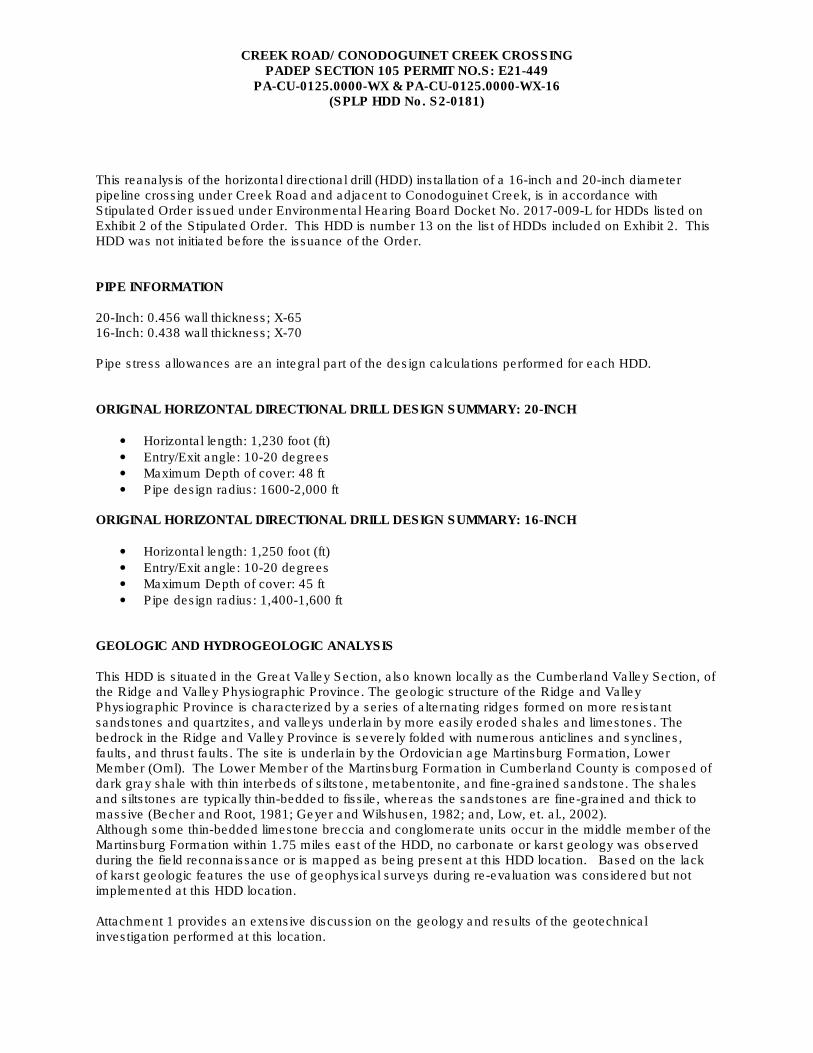
This reanalysis of the horizontal directional drill (HDD) installation of a 16-inch and 20-inch diameter pipeline crossing under Creek Road and adjacent to Conodoguinet Creek, is in accordance with Stipulated Order issued under Environmental Hearing Board Docket No. 2017-009-L for HDDs listed on Exhibit 2 of the Stipulated Order. This HDD is number 13 on the list of HDDs included on Exhibit 2. This HDD was not initiated before the issuance of the Order. PIPE INFORMATION 20-Inch: 0.456 wall thickness; X-65 16-Inch: 0.438 wall thickness; X-70 Pipe stress allowances are an integral part of the design calculations performed for each HDD. ORIGINAL HORIZONTAL DIRECTIONAL DRILL DESIGN SUMMARY: 20-INCH
• Horizontal length: 1,230 foot (ft)
• Entry/Exit angle: 10-20 degrees
• Maximum Depth of cover: 48 ft
• Pipe design radius: 1600-2,000 ft
ORIGINAL HORIZONTAL DIRECTIONAL DRILL DESIGN SUMMARY: 16-INCH
• Horizontal length: 1,250 foot (ft)
• Entry/Exit angle: 10-20 degrees
• Maximum Depth of cover: 45 ft
• Pipe design radius: 1,400-1,600 ft GEOLOGIC AND HYDROGEOLOGIC ANALYSIS This HDD is situated in the Great Valley Section, also known locally as the Cumberland Valley Section, of the Ridge and Valley Physiographic Province. The geologic structure of the Ridge and Valley Physiographic Province is characterized by a series of alternating ridges formed on more resistant sandstones and quartzites, and valleys underlain by more easily eroded shales and limestones. The bedrock in the Ridge and Valley Province is severely folded with numerous anticlines and synclines, faults, and thrust faults. The site is underlain by the Ordovician age Martinsburg Formation, Lower Member (Oml). The Lower Member of the Martinsburg Formation in Cumberland County is composed of dark gray shale with thin interbeds of siltstone, metabentonite, and fine-grained sandstone. The shales and siltstones are typically thin-bedded to fissile, whereas the sandstones are fine-grained and thick to massive (Becher and Root, 1981; Geyer and Wilshusen, 1982; and, Low, et. al., 2002). Although some thin-bedded limestone breccia and conglomerate units occur in the middle member of the Martinsburg Formation within 1.75 miles east of the HDD, no carbonate or karst geology was observed during the field reconnaissance or is mapped as being present at this HDD location. Based on the lack of karst geologic features the use of geophysical surveys during re-evaluation was considered but not implemented at this HDD location. Attachment 1 provides an extensive discussion on the geology and results of the geotechnical investigation performed at this location.
CREEK ROAD/ CONODOGUINET CREEK CROSSING PADEP SECTION 105 PERMIT NO.S: E21-449
PA-CU-0125.0000-WX & PA-CU-0125.0000-WX-16 (SPLP HDD No. S2-0181)
HYDROGEOLOGY, GROUND WATER, AND WELL PRODUCTION ZONES Geologic factors such as rock type, intergranular porosity, rock strata inclination, faults, joints, bedding planes, and solution channels affect groundwater movement and availability. According to Becher and Root (1981), the Martinsburg Formation is the uppermost rock unit in the vicinity of this HDD. Groundwater flow paths within the clastic rocks have both local and regional components, which are controlled by bedding, cleavage, and fractures in the rock. Locally, shallow groundwater discharges to the gaining portions of nearby streams such as Conodoguinet Creek, and deeper regional groundwater flow is toward points of regional groundwater discharge such as the Susquehanna River. Based on the geotechnical report and boring logs, groundwater was not encountered in SB-01 or SB-02, which were drilled to 35 feet below ground surface (bgs) and 11 feet bgs, respectively. In the recently completed geotechnical drilling, groundwater was measured in Boring B-01 at a depth of 138.5 feet bgs on August 22, 2017. The groundwater flow direction in the overburden soils is presumed to mimic surface topography, which slopes gently to the south toward the unnamed tributary and Conodoguinet Creek. The unnamed tributary and Conodoguinet Creek are sustained by local shallow groundwater flow discharges. The unnamed tributary flows to the east beginning near the western exit point of the HDD and eventually discharges to the Conodoguinet Creek. The geotechnical report and boring logs show that no groundwater was present in the unconsolidated soils and the depth to water can be quite deep proximate to the HDD path based on a measured depth to water of 138.5 feet bgs. Based on the Pennsylvania Groundwater Information System (PaGWIS) database, 22 wells occur within the 0.5-mile radius of the HDD. These wells consist of 11 private supply wells, 6 groundwater monitoring wells, and 4 abandoned wells (likely former groundwater monitoring wells) and one “anode” well. The 6 groundwater monitoring wells and 4 abandoned wells are associated with the Turkey Hill gas station located at 1 Cranes Gap Road approximately 0.5 mile east of the HDD site in the Village of Schlusser. Based upon incomplete information in the PaGWIS database, the majority of the identified water wells were completed as 6-inch-diameter open-rock wells at depths ranging from 83 to 241 feet bgs, depth to bedrock ranges from 10 to 92 feet bgs, and well construction consists of 38 to 94 feet of steel casing with the open-rock portions of the wells extending from 31 feet to 202 feet bgs. Reported well yields range from 10 to 25 gallons per minute. Seven static water level measurements were reported and range from 20 to 60 feet bgs. Based on the geologic mapping available for the area, it appears that the majority of the wells identified above were completed in the Martinsburg Formation. All the private water supply wells identified within a 0.5-mile radius of the HDD are constructed in bedrock indicating that none of these wells relies on the shallow unconsolidated overburden as a source of groundwater supply. The HDD profiles indicate that drilling will penetrate fractured bedrock at depths of up to 80 feet bgs. This depth interval is the same bedrock interval from which some of the wells are believed to derive their groundwater supplies (31 to 202 feet bgs); however, the PaGWIS database does not provide detailed information regarding the water-bearing zone depths penetrated by the wells. Given the lack of readily available water-bearing zone information, absence of identified groundwater supply wells within 1,000 feet of the proposed HDD, and local geologic structure, the potential for water supply impacts to occur as a result of the proposed HDD operations is considered to be negligible. The production zone for waters wells within bedrock is from the well bottom to highest point of water inflow from the water bearing seams, joints, and fractures in the rock formation. Attachment 1 provides an extensive discussion on the hydrogeology and results of the geotechnical investigation performed at this location.
CREEK ROAD/ CONODOGUINET CREEK CROSSING PADEP SECTION 105 PERMIT NO.S: E21-449
PA-CU-0125.0000-WX & PA-CU-0125.0000-WX-16 (SPLP HDD No. S2-0181)
INADVERTENT RETURN (IR) DISCUSSION HDD specialists for Sunoco Pipeline, L.P. (SPLP) reviewed the original design profiles for the 16 and 20-HDDs and determined there was an increased risk of an IR during the undercrossing of Creek Road and while parallel to the Conodoguient Creek channel due to the shallow depth of profile as summarized in the HDD design data above, and orientation of the profile centerline to the creek channel. As presented and discussed in the conclusions section below, the profile for both the 16 and 20-inch pipelines have been re-orientated and redesigned longer in extent to allow for an increase in the profile depth below the creek, with a lateral shift to offset the HDD away from the creek channel. The re-designed HDD profile has been relocated to the north beyond the Conodoguinet Creek and lengthened to allow for deeper crossings beneath the unnamed tributary stream, sanitary sewer, and culvert. The inclination of the entry and exit angles has been increased as a means to install the pipe through these protective soils, residual soils, and bedrock in closer proximity to the entry and exit points than the original, shorter profile. From a geologic perspective, the laterally adjusted, longer and deeper profile, in conjunction with the proposed engineering controls and drilling best management practices, will
assist to reduce the risk of an IR. The new geotechnical data utilized for this HDD reanalysis and redesign was obtained 1,500 ft downstream within the floodplain of Conodoguinet Creek at an equivalent setting. The geotechnical core results shows 14 ft of overburden above bedrock consisting of shale from initial bedrock down to HDD profile depth of -80 ft as shown on the geotechnical core data presented in the hydrogeological report in Attachment 1. Bedrock entry is into shale having a recovery value of 44 and RQD value of “0”. The rock integrity transitions at -30 ft to a recovery value of 100. This recovery value of 100 is consistent down the maximum depth of the HDD profile. The rock strength, RQD value, at 30 ft of depth is 31, and consistently improves with depth below ground until at profile depth the RQD value is 73. The increase in the profile depth, is by itself, a means to minimize the potential for IR’s to occur during these HDDs. SPLP has a HDD crossing of Conodoguinet Creek in process approximately 1/5 mile downstream (east). As of the date of this reanalysis, this HDD has progressed 1,600 ft into the pilot phase of a 2,405 ft total HDD profile without an IR or other incidents. ADJACENT FEATURES ANALYSIS The crossing of Creek Road and Conodoguient Creek is located in Cumberland County, approximately 2.9 miles north of Carlisle, PA., and 0.4 miles west of Spring Road. At this location the pipeline route follows parallel to two (2) previously existing pipelines and a local electrical distribution line. The general area surrounding the HDD includes unmanaged deciduous woodlands, pasture, croplands, individual homesites, and residential neighborhoods. The wooded area immediately north of the HDD, and north of Creek Road is owned by the township and managed as greenspace. As noted previously, according to the PaGWIS database, 11 private water supply wells exist within 0.5 miles of the HDD profile. None of these wells, however, are located within 450 ft of the HDD profile. SPLP has identified all landowners with property located within 450 ft of the HDD alignment. There are nineteen (19) individual landowners with properties located within 450 ft of the HDD alignment. SPLP sent each of these landowners a notice letter via both certified and first class mail on October 30, 2017, that included an offer to sample the landowner’s private water supply/well in accordance with the terms of the Order and the Water Supply Assessment, Preparedness, Prevention and Contingency Plan. The letter also requested that each landowner contact the Right-of-Way agent for the local area and provide SPLP with
CREEK ROAD/ CONODOGUINET CREEK CROSSING PADEP SECTION 105 PERMIT NO.S: E21-449
PA-CU-0125.0000-WX & PA-CU-0125.0000-WX-16 (SPLP HDD No. S2-0181)
information regarding: (1) whether the landowner has a well; (2) where that well is located, and its depth and size if known; and (3) whether the landowner would like to have the well sampled. In accordance with paragraph 10 of the Order, copies of the certified mail receipts for the letters sent to landowners have been provided to Karyn Yordy, Executive Assistant, Office of Programs at the Department’s Central Office. If any landowner with the 450 ft HDD alignment fails to respond by November 15, 2017, agents for SPLP will initiate direct contact by phone or in person to attempt to determine the potable water source for each landowner. Based on the response to the mailings and direct contact, the landowners with private water wells determined to be at risk during the HDD will be offered alternative water supplies until the HDD is complete. ALTERNATIVES ANALYSIS As required by the Order, the reanalysis of S2-0181 includes an evaluation of open cut alternatives and a re-route analysis. As part of the PADEP Chapter 105 permit process for the Mariner II East Project, SPLP developed and submitted for review a project-wide Alternatives Analysis. During the development and siting of the Project, SPLP considered several different routings, locations, and designs to determine whether there was a practicable alternative to the proposed impact. SPLP performed this determination through a sequential review of routes and design techniques, which concluded with an alternative that has the least environmental impacts, taking into consideration cost, existing technology, and logistics. The baseline route provided for the pipeline construction was to cross every wetland and stream on the project by open cut construction procedures. The Alternatives Analysis submitted to PADEP conceptually analyzed the potential feasibility of any alternative to baseline route trenched resource crossings (e.g., reroute, conventional bore, HDD). The decision-making processes for selection of the HDD instead of an open cut crossing methodology is discussed thoroughly in the submitted alternatives analysis and was an important part of the overall PADEP approval of HDD plans as currently permitted. As described below, the open cut and re-route analyses have confirmed the conclusions reached in the previously submitted Alternatives Analysis. The revised 20-inch and 16-inch HDDs are 1,450 ft and 1,400 ft in horizontal length respectively and includes the crossing of one minor stream channel and Creek Road. The channel of Conodoguinet Creek occurs immediately south of the HDD centerline but does not overlie the HDD. Emergent wetlands occur immediately east and west of the eastern HDD entry/exit point. Open-cut Analysis SPLP’s original plan of construction, which was replaced by the HDD’s subject to this analysis, was a 0.65-mile-long conventional construction route north of the adjacent power line through the unmanaged woodlands owned by the township. The township utilized funding from the National Park Service (NPS) in part to acquire this tract, and the NPS retains the right of review regarding the granting of any encumbrances on this tract. This construction concept was pursued for an extended timeframe before being revised to an HDD alternative. The NPS was unwilling to grant an easement conventional construction to SPLP under any terms. Re-Route Analysis The pipeline route as currently permitted follows parallel to two (2) existing pipelines, and passes through a gap in the residential development across the larger area. There are no existing utility corridors to the north or south that provide a practical alternative route. Any alternate route considered north or south of the existing utility corridor would require the clearing of a new “greenfield” corridor through existing woodlands and croplands, increase the number of stream crossings,
CREEK ROAD/ CONODOGUINET CREEK CROSSING PADEP SECTION 105 PERMIT NO.S: E21-449
PA-CU-0125.0000-WX & PA-CU-0125.0000-WX-16 (SPLP HDD No. S2-0181)
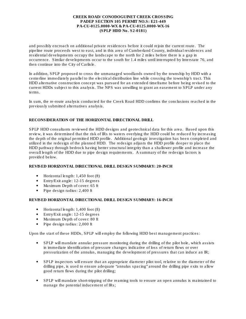
and possibly encroach on additional private residences before it could rejoin the current route. The pipeline route proceeds west to east, and in this area of Cumberland County, individual residences and residential developments occupy the landscape to the north for 2 miles before there is a gap in occurrence. Similar developments occur to the south for 1.4 miles until interrupted by Interstate 76, and then continue into the City of Carlisle. In addition, SPLP proposed to cross the unmanaged woodlands owned by the township by HDD with a centerline immediately parallel to the electrical distribution line while crossing the township’s tract. This HDD alternative construction concept was pursued for an extended timeframe before being revised to the current HDDs subject to this analysis. The NPS was unwilling to grant an easement to SPLP under any terms. In sum, the re-route analysis conducted for the Creek Road HDD confirms the conclusions reached in the previously submitted alternatives analysis. RECONSIDERATION OF THE HORIZONTAL DIRECTIONAL DRILL SPLP HDD consultants reviewed the HDD designs and geotechnical data for this area. Based upon this review, it was determined that the risk of IRs to waters overlying the HDD could be reduced by increasing the depth of the original permitted HDD profile. Additional geologic investigation has been completed and utilized in the redesign of the planned HDD. The redesign adjusts the HDD profile deeper to place the HDD pathway through bedrock having better structural integrity than a shallower profile and increase the overall length of the HDD due to pipe design requirements. A summary of the redesign factors is provided below. REVISED HORIZONTAL DIRECTIONAL DRILL DESIGN SUMMARY: 20-INCH
• Horizontal length: 1,450 foot (ft)
• Entry/Exit angle: 12-15 degrees
• Maximum Depth of cover: 65 ft
• Pipe design radius: 2,400 ft
REVISED HORIZONTAL DIRECTIONAL DRILL DESIGN SUMMARY: 16-INCH
• Horizontal length: 1,400 foot (ft)
• Entry/Exit angle: 12-15 degrees
• Maximum Depth of cover: 80 ft
• Pipe design radius: 2,000 ft Upon the start of these HDDs, SPLP will employ the following HDD best management practices:
• SPLP will mandate annular pressure monitoring during the drilling of the pilot hole, which assists in immediate identification of pressure changes indicative of loss of return flows or over pressurization of the annulus, managing the development of pressures that can induce an IR;
• SPLP inspectors will ensure that an appropriate diameter pilot tool, relative to the diameter of the drilling pipe, is used to ensure adequate “annulus spacing” around the drilling pipe exits to allow good return flows during the pilot drilling;
• SPLP will mandate short-tripping of the reaming tools to ensure an open annulus is maintained to manage the potential inducement of IRs;
CREEK ROAD/ CONODOGUINET CREEK CROSSING PADEP SECTION 105 PERMIT NO.S: E21-449
PA-CU-0125.0000-WX & PA-CU-0125.0000-WX-16 (SPLP HDD No. S2-0181)
• SPLP will require monitoring of the drilling fluid viscosity, such that fissures and fractures in the subsurface are sealed during the drilling process;
• During the reaming phase, the use of Loss Control Materials can be implemented if indications of a potential IR are noted or an IR is observed; and
• If necessary, the pilot hole and reaming phases at the east point of entry for the HDD may utilize casing, hammered into the substrate down to structurally better rock, to prevent vertical or lateral movement of drilling fluids at shallow depths.
CONCLUSION It is SPLP’s intent to modify the original profile design and to pursue a deeper and longer HDD profile. Figures 1 and 3 in Attachment 2 presents the original HDD plan and profiles. Figures 2 and 4 presents the revised HDD plan and profiles.
CREEK ROAD/ CONODOGUINET CREEK CROSSING PADEP SECTION 105 PERMIT NO.S: E21-449
PA-CU-0125.0000-WX & PA-CU-0125.0000-WX-16 (SPLP HDD No. S2-0181)
ATTACHMENT 1
GEOLOGY AND HYDROGEOLOGICAL EVALUATION REPORT
We answer to you. 3020 Columbia Avenue, Lancaster, PA 17603 ● Phone: (800) 738-8395 E-mail: [email protected] ● Website: rettew.com
November 29, 2017 Mr. Matthew Gordon
Sunoco Pipeline, L.P. 535 Fritztown Road Sinking Spring, PA 19608 RE: Sunoco Pipeline, L.P. Pipeline Project - Mariner East II
Creek Road Horizontal Directional Drill Location (S2-0181) Hydrogeological Re-Evaluation Report
North Middleton Township, Cumberland County, Pennsylvania RETTEW Project No. 096302011
Dear Mr. Gordon:
RETTEW Associates, Inc. is pleased to provide the enclosed Hydrogeological Re-Evaluation Report for the Yellow Breeches Creek Horizontal Directional Drill (HDD) Location (S2-0181). This HDD Re-Evaluation Report was performed as required by the Corrected Stipulated Order dated August 10, 2017. Please note that the HDD Re-Evaluation Report for S2-0181 was prepared by Skelly and Loy, Inc. (Skelly & Loy) under subcontract to RETTEW. Mr. Douglas Hess, Director of Groundwater and Site Characterization Services, was the Professional Geologist (PG) at Skelly and Loy that supervised the work for this report.
If you have any questions regarding the Hydrogeological Re-Evaluation Report for HDD S2-0181, please
do not hesitate to call Mr. Hess at (717) 232-1799.
Sincerely,
Matthew T. Bruckner, PG
Project Manager
Enclosure Z:\Shared\Projects\09630\096302011\GS\Hydrogeology Review\Creek Road\Final\Creek Road Cover Letter 11-29-17.docx
Engineers
Environmental Consultants
Surveyors
Landscape Architects
Safety Consultants
449 Eisenhower Boulevard, Suite 300 Harrisburg, PA 17111-2302
E-mail: [email protected] Internet: www.skellyloy.com
Mr. Matthew Gordon Sunoco Pipeline, L.P. 535 Fritztown Road Sinking Spring, Pennsylvania 19608
EXECUTIVE SUMMARY
November 29, 2017
Phone: 717-232-0593 800-892-6532
Fax: 717-232-1799
Re: Sunoco PA Pipeline Project Mariner East II, Creek Road/Conodoguinet Creek #1 Horizontal Directional Drill (HOD), Location (S2-0181) Hydrogeological Re-evaluation Report North Middleton Township, Cumberland County, Pennsylvania Rettew Project No. 096302011
1. The 20-inch and 16-inch S2-0181 Creek Road/Conodoguinet Creek #1 Horizontal Directional Drill (HOD) locations are included in the Corrected Stipulated Order of August 10, 2017, requiring re-evaluation, including a geologic report.
2. HOD Creek Road/Conodoguinet Creek #1 is underlain by sedimentary rocks of the Ordovician age Martinsburg Formation (0ml).
3. Geologic mapping, published reports , and fie ld observations indicate a high degree of bedrock fracturing in the Martinsburg Formation characterized by irregularly spaced, generally open, highly developed joints with steeply dipping beds and dominant beddingparallel fracture cleavage.
4. Water-bearing zones generally occur in secondary openings along bedding planes, joints, faults, and fractures. Water-bearing zones in the Martinsburg Formation are reported to be distributed within the first 100 feet of the subsurface but occur as deep as 350 feet below the ground surface (bgs).
5. To date, no HOD operations have been started at the Creek Road/Conodoguinet Creek #1 site for the proposed 20-inch or 16-inch pipelines.
6. Based on the hydro-structural characteristics of the underlying geology and the proposed HOD profiles within shallow unconsolidated soil materials and generally shallow bedrock, the Creek Road/Conodoguinet Creek #1 proposed 20-inch and 16-inch HDDs are susceptible to the inadvertent return of drilling fluids during HOD operations. A redesigned HOD profile and Best Management Practices (BMPs) during drilling operations will be used to reduce the risk of an inadvertent return (IR).
Office Locations: Pittsburgh, PA Morgantown, WV State College, PA Hagerstown, MD Hunt Valley, MD
Mr. Matthew Gordon Sunoco Pipeline, L.P. RETTEW Project No. 096302011 Page 2 November 29, 2017 1.0 INTRODUCTION
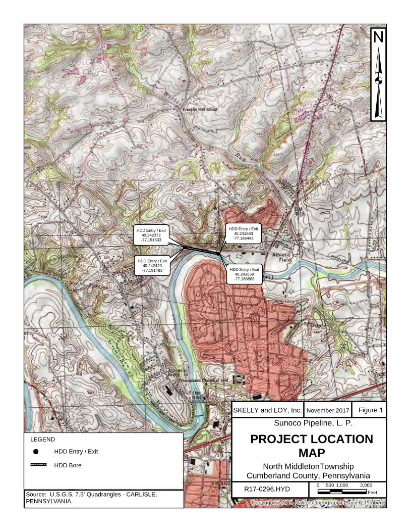
The purpose of this report is to describe the hydrogeologic setting of the Creek Road/Conodoguinet Creek #1 (S2-0181) HDD location on the Sunoco Pipeline, L.P. (SPLP) Penn-sylvania Pipeline Project-Mariner East II (PPP-ME2) Project. The Creek Road/Conodoguinet Creek #1 HDD (the site) is located in North Middleton Township, Cumberland County, Penn-sylvania. The site is located approximately 2.75 miles north of Carlisle and approximately 1.5 miles north of the Pennsylvania Turnpike (I-76). The HDD was designed to be drilled adjacent to Conodoguinet Creek and under Creek Road, a small tributary discharging to the Conodoguinet Creek, a sanitary sewer, and culvert (refer to Figure 1). This hydrogeologic report is part of the response to the Corrected Stipulated Order dated August 10, 2017, related to the potential for the inadvertent return of drilling fluids during proposed drilling operations. HDD S2-0181 is located within the Great Valley Section of the Ridge and Valley Physio-graphic Province (Pennsylvania Department of Conservation and Natural Resources [PA DCNR], 2000). The dominant topography in areas underlain by the Martinsburg Formation is typified by alternating ridges formed on more resistant sandstones and quartzites and valleys of low relief underlain by more easily eroded shales and limestones. Local relief is low to moderate and ranges in the vicinity of the site from approximately 404 feet above mean sea level (AMSL) to 453 feet AMSL (Google Earth, 2017). The site is drained by both a shallow, unnamed tributary stream and the adjacent Conodoguinet Creek which flows from west to east along the proposed east-west HDD path. The unnamed tributary flows to the south across the western half of the HDD trace where it discharges into Conodoguinet Creek. The area surrounding the HDD consists predominantly of suburban residential properties with some small, interspersed areas of residual, semi-rural land uses (e.g., farming, agriculture). The proposed re-designed 20-inch HDD entry point is at a surface elevation of 404 feet AMSL and forms a slightly concave HDD profile that slopes gently upward toward the west to an elevation of 453 feet AMSL at the HDD exit point. The proposed redesigned 20-inch HDD will cross under the single unnamed tributary stream and Creek Road at 43 feet bgs, the sanitary sewer at 29 feet bgs, and the culvert at 29 feet bgs. The proposed redesigned 16-inch HDD entry point is at a surface elevation of 405 feet AMSL sloping gently upward toward the west to an elevation of 448 feet AMSL at the HDD exit point. The 16-inch HDD will cross under Creek Road at 61 feet bgs, the single unnamed tributary stream at 58 feet bgs, the sanitary sewer at 60 feet bgs, and the culvert at 21 feet bgs. The proposed 20-inch and 16-inch HDDs are located between Stations 9956+00 and 9972+00 on the pipeline, for an overall horizontal length of 1,450 feet (20-inch HDD) and 1,400 feet (16-inch HDD). The proposed S2-0181 HDD locations are shown on Figure 1. 2.0 GEOLOGY AND SOILS
Twelve available published and online references were reviewed to evaluate the hydrogeology and soils present in the vicinity of the proposed Creek Road/Conodoguinet Creek
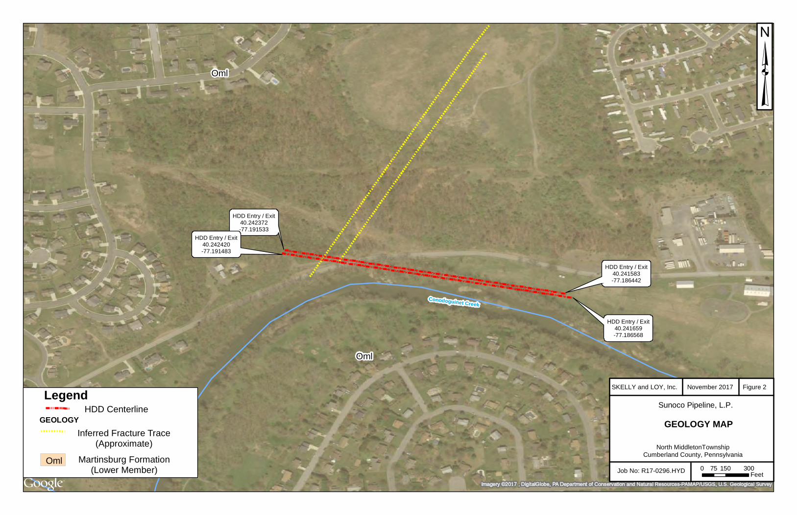
Mr. Matthew Gordon Sunoco Pipeline, L.P. RETTEW Project No. 096302011 Page 3 November 29, 2017 #1 HDD (S2-0181). Detailed descriptions of the soils and bedrock geology underlying S2-0181 are included in the following section. According to the United States Department of Agriculture Soil Survey of Cumberland County, Pennsylvania, soils within 450 feet of the drill path for HDD S2-0181 consist of Atkins silt loam (Aw); Berks channery silt loam (BeB); Blairton silt loam (BpB); Middlebury soils (Mf); Monongahela silt loam, 3 to 8% slopes (MnB); Monongahela silt loam, 8 to 15% slopes (MnC); Purdy silt loam (Pu); Weikert very channery silt loam, 8 to 15% slopes (WeC); Weikert very channery silt loam, 15 to 25% slopes (WeD); and Weikert and Klinesville very shaly silt loams, 25 to 75% slopes (WkF). A site map showing the spatial distribution of the various soils along with the soil profile descriptions is included as Attachment 1. The S2-0181 HDD site is situated in the Great Valley Section, also known locally as the Cumberland Valley Section, of the Ridge and Valley Physiographic Province. The geologic structure of the Ridge and Valley Physiographic Province is characterized by a series of alternating ridges formed on more resistant sandstones and quartzites and valleys underlain by more easily eroded shales and limestones. The bedrock in the Ridge and Valley Province is severely folded with numerous anticlines and synclines, faults, and thrust faults. The site is underlain by the Ordovician age Martinsburg Formation, Lower Member (Oml). The bedrock geology at the site is identified on Figure 2. The Lower Member of the Martinsburg Formation in Cumberland County is composed of dark gray shale with thin interbeds of siltstone, metabentonite, and fine-grained sandstone. The shales and siltstones are typically thin-bedded to fissile, whereas the sandstones are fine-grained and thick to massive (Becher and Root, 1981; Geyer and Wilshusen, 1982; and, Low, et. al., 2002). According to Geyer and Wilshusen (1982), fracturing in the Martinsburg Formation underlying the HDD S2-0181 site is typified by cleavage parallel to the bedding planes; however, irregularly spaced, naturally occurring fractures known as joints are also present. These joints are typically open and nearly vertical. The joint and bedding plane openings collectively provide a secondary porosity of low magnitude. The formation is moderately weathered to an approximate depth of 1 to 4 feet bgs. The topography is characterized as a valley of low relief dissected by ravines and small stream beds. Drainage patterns are typically dendritic and trellis. Natural slopes are steep and often unstable, with cut slope stability ranging from fair in the shale to good in the sandstone. The overlying soil mantle is generally thick. The formation is moderately easy to excavate in shale and difficult in sandstone. The rock reportedly provides good foundation stability if excavated to sound rock. The drilling rate is reasonably fast. 3.0 HYDROGEOLOGY
Bedrock geology ultimately influences the storage, transmission, and use of groundwater. Geologic factors such as rock type, intergranular porosity, rock strata inclination,
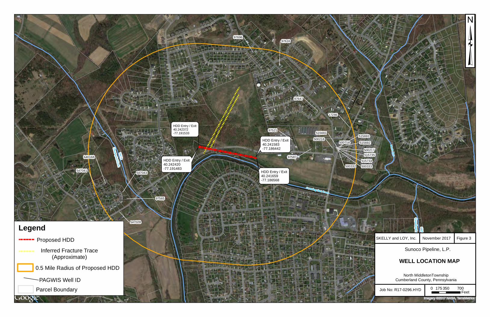
Mr. Matthew Gordon Sunoco Pipeline, L.P. RETTEW Project No. 096302011 Page 4 November 29, 2017 faults, joints, bedding planes, and solution channels affect groundwater movement and availability. According to Becher and Root (1981), the Martinsburg Formation is the uppermost rock unit in the vicinity of the HDD S2-0181. Groundwater flow paths within the clastic rocks have both local and regional components which are controlled by bedding, cleavage, and fractures in the rock. Locally, shallow groundwater discharges to the gaining portions of nearby streams such as Conodoguinet Creek, and deeper regional groundwater flow is toward points of regional groundwater discharge such as the Susquehanna River. Based on the geotechnical report and boring logs included as Attachment 2, groundwater was not encountered in SB-01 or SB-02, which were drilled to 35 feet bgs and 11 feet bgs, respectively. In the recently completed geotechnical drilling, groundwater was measured in Boring B-01 at a depth of 138.5 feet bgs on August 22, 2017. The maximum reported well yield in the Martinsburg Formation is 200 gallons per minute (gpm). Water-bearing zones are commonly less than 100 feet in depth bgs, but occur as deep as 350 feet bgs (Taylor and Werkheiser, 1984). According to Becher and Root (1981), the frequency of water-bearing zones declines gradually to 350 feet bgs. Cleavage is important in creating water-bearing openings, particularly in the Martinsburg Formation where it provides numerous closely spaced, commonly minute openings which, individually, cannot provide much water to wells but, collectively, are capable of providing domestic supplies. Well records from the PA DCNR Pennsylvania Groundwater Information System (PaGWIS) database were reviewed to identify domestic water supply wells located within a 0.5-mile radius of the proposed HDD right-of-way boundary (PaGWIS, 2017). The search identified 22 wells within the 0.5-mile radius of the HDD. These wells consist of 11 private supply wells, 6 groundwater monitoring wells, and 4 abandoned wells (likely former groundwater monitoring wells and one “anode” well). Ten (10) of the 22 identified wells consist of groundwater monitoring wells associated with the Turkey Hill gas station located at 1 Cranes Gap Road, approximately 0.5 mile east of the HDD site in the Village of Schlusser. A map showing the well locations relative to the proposed HDD location is included as Figure 3. Well construction details were not reported for all of the wells. Based on incomplete information in the PaGWIS database (Figure 3), it appears that the majority of the identified wells were completed as 6-inch-diameter open-rock wells at depths ranging from 83 to 241 feet bgs. The monitoring wells are shallow, 4-inch-diameter wells located at commercial properties and range in depth from 6 to 17 feet bgs. Based solely on the PaGWIS database, the depth to bedrock ranges from 10 to 92 feet bgs, and well construction consists of 38 to 94 feet of steel casing with the open-rock portions of the wells extending from 31 feet to 202 feet bgs. Reported well yields range from 10 to 25 gpm. Seven static water level measurements were recorded and range from 20 to 60 feet bgs. Based on the geologic mapping available for the area, it appears that the majority of the wells identified above were completed in the Martinsburg Formation. 4.0 FRACTURE TRACE ANALYSIS
Fracture traces are natural linear features that are unaffected by local topographic relief and, as a result, are considered surface manifestations of concentrated high-angle bedrock
Mr. Matthew Gordon Sunoco Pipeline, L.P. RETTEW Project No. 096302011 Page 5 November 29, 2017 fracturing. Fracture traces may be observed on aerial photographs as linear topography, straight stream segments, vegetation, or soil tonal alignments. The Web-based Pennsylvania Imagery Navigator and Google Earth Pro were used to access, download, and view aerial imagery of the HDD site. Ten series of historical aerial photographs were analyzed that included photography dated April 1994, March 1995, April 2003, September 2005, October 2006, March 2007, October 2008, September 2010, August 2012, and April 2016 (Pennsylvania Spatial Data Access [PASDA], 2017, and Google Earth Pro, 2017). Due to the degree and extent of residential development in the area, no fracture traces were discernible proximate to the HDD. According to Becher and Root (1981), three fracture traces were previously identified in the area north of the HDD site. Two of these mapped fracture traces are parallel and trend northeast-southwest at a low angle intersecting the HDD profile at locations approximately 250 and 350 feet east of the proposed HDD exit point (western end of HDD). A third fracture trace is mapped as trending northwest-southeast approximately 2,000 feet north of the HDD. The identified fracture traces are related to the primary geologic structure in the vicinity of the HDD site. The two northeast-southwest trending fracture traces are presented on both the Geology Map (Figure 2) and the Groundwater Well Location Map (Figure 3). The general surface drainage patterns near the HDD site are characterized by the linear stream reaches of the Conodoguinet Creek and several surface streams generally trending northwest-southeast and southwest-northeast which appear to reflect this local geologic structure. 5.0 GEOTECHNICAL EVALUATION
Three geotechnical borings were completed in 2016 and 2017 during the preliminary investigation of HDD S2-0181 and prior to initiating HDD operations. The three borings are located in the vicinity of the HDD limit of disturbance (LOD) as shown in Attachment 2. The boring logs and other supporting information are included as Attachment 2. The borings were completed to investigate soil, residual soil, and bedrock conditions using hollow-stem augers with split spoons for soil sampling and a core barrel/bit for rock coring. The preliminary geotechnical investigation was performed in two phases. Two shallow borings (SB-01 and SB-02) were completed on October 24, 2016, and an additional boring (Boring B-01) was completed between August 21 and 22, 2017. SB-01 was located approximately 75 feet southeast of the proposed HDD exit point, and SB-02 was located 240 feet west of the proposed HDD entry point. Boring B-01 was located approximately 450 feet northwest of the proposed HDD exit point. The generalized subsurface profile observed in the borings is described as follows.
• SB-01: The top three inches consisted of topsoil. The interval from approximately 0.3 to 26.5 feet consisted of partially weathered SLATE and from 26.5 to 35.0 feet of moderately fractured SLATE. The total depth of the boring was 35.0 feet bgs. Groundwater was not encountered.
Mr. Matthew Gordon Sunoco Pipeline, L.P. RETTEW Project No. 096302011 Page 6 November 29, 2017
• SB-02: The top four inches consisted of topsoil. The interval from 0.3 to 11.0 feet consisted of SILT with a trace of fine sand. Partially weathered SLATE was found at 11.0 feet. The total depth of the soil boring was 11.0 feet bgs where auger refusal was encountered. Groundwater was not encountered.
• B-01: The upper 9.0 feet consisted of highly to completely weathered SHALE; from 9.0 to 128.5 feet was slightly weathered, very broken to massive SHALE; from 128.5 to 135.0 feet was slightly weathered, very broken to massive calcareous SHALE; from 135.0 to 138.0 feet was slightly weathered, broken to massive SHALE; and from 138.0 to 175.0 feet was weathered to slightly weathered, very broken to massive SHALE. Total depth of the boring was 175.0 feet. Groundwater was encountered at 138.5 feet bgs.
The boring logs indicate that the soil (weathered bedrock)/bedrock interface ranges from approximately 9 feet (B-01) to 25 feet (SB-01) bgs. Please note that Skelly and Loy/RETTEW did not oversee or direct the geotechnical drilling programs associated with the S2-0181 HDD including, but not limited to, the selection of boring locations, determination of location, determination of surface elevation, target depths, observations of rock cores during drilling operations, and preparation of boring logs. The geotechnical reports, boring logs, and core photographs that resulted from these programs were generated by other Sunoco Pipeline, L.P. contractors. Skelly and Loy/RETTEW relied on these reports and incorporated their data into the general geologic and hydrogeologic framework of the analysis of proposed S2-0181 Creek Road/Conodoguinet Creek #1 HDD for this report. 6.0 FIELD OBSERVATIONS
Based on a site reconnaissance performed by a Skelly and Loy geologist on October 4, 2017, there are extensive bedrock exposures in the vicinity of the HDD exit point that occur in cut slopes along Creek Road. These bedrock exposures consist predominantly of dark gray shale with thin interbeds of siltstone, metabentonite, and fine-grained sandstone characteristic of the Lower Member of the Martinsburg Formation. The shales and siltstones are typically thin-bedded to fissile whereas the sandstones are fine-grained and thick to massive. Structural geologic measurements indicate that the intense fracturing of these rocks is dominantly controlled by regional northeast-trending cleavage. Field measurements along the cut slope exposures indicate that cleavage ranges from N25-30°E with dips ranging from 65°SE to vertical. Field measurements of bedrock strike ranged from N64-90°E with bedding dips of 40°SE to near vertical. Jointing was observed to occur as rectangular sets in which the individual joints are vertical to nearly vertical and spaced from a few inches to a foot apart. The joint sets observed are both parallel and perpendicular to the strike of bedding with the perpendicular set being the
Mr. Matthew Gordon Sunoco Pipeline, L.P. RETTEW Project No. 096302011 Page 7 November 29, 2017 most pronounced. The measured orientation of the most abundant and closely spaced joint set ranges from N5°E to N14°E with dips ranging from 52°SE to 84°SE. A second bedding-parallel joint set ranged between N40°E and 70°E with high-angle dips between 60° and vertical. A third bedding-perpendicular joint set was measured to be between N35° and 50°W with a near-vertical dip. According to available geologic mapping, the entire HDD bore path is underlain by bedrock mapped as the Lower Member of the Martinsburg Formation; this mapping is consistent with Skelly and Loy’s field observations. Based on local topography and bedrock dip reported in the published literature (Dyson, 1967), the mean direction of cleavage dip is south between 30º and 90° with a mean of 65º to 70°, the major joint set strikes between N45°E and N62°E with dips varying between 65º and 80° northwest, and bedrock strike generally between 40° and 80° to the north-northeast which are consistent with the field observations and geologic measurements of the Martinsburg Formation near the HDD exit point. In addition to the unnamed tributaries and private water supplies, an additional potential environmental receptor of concern was identified within the defined 0.5-mile HDD buffer area. This potential receptor consists of a farm, livestock barns, and associated commercial property situated approximately 1,000 feet east of the HDD entry point. 7.0 GEOPHYSICAL SURVEY CONSIDERATIONS
Although some thin-bedded limestone breccia and conglomerate units occur in the middle member of the Martinsburg Formation within 1.75 miles east of the HDD, no carbonate or karst geology was observed during the field reconnaissance or is mapped as being present at this HDD location. Although the Corrected Stipulated Order states that the use of geophysical surveys should be considered in karst areas, based on the lack of karst geologic features and extensively fractured bedrock, the use of geophysical surveys during re-evaluation was considered but was ultimately not implemented at the Creek Road/Conodoguinet Creek #1 HDD location because the results of geophysical surveys would not likely provide additional information that would reduce the risk of an IR. In addition, results of geophysical surveys in karst terrains with the resolution necessary to image features that could affect the HDD are typically limited to the upper 20 to 50 feet of the ground surface. Based on our experience working in karst geology, the lack of mapped karst geology along the HDD trace and lack of continuous thick-bedded limestone units, the Martinsburg Formation is not deemed susceptible to the solution activity present in other more thickly bedded carbonate geologic formations in Pennsylvania. In our professional opinion, geophysical surveys would not provide additional information on the formational thickness, interbedded siltstone, metabentonite, fine-grained sandstone, siltstones, and thinly bedded fissile shales at depths greater than 50 feet bgs along the HHD profile. Geophysical survey data would not enhance the evaluation or reduce the risk of an IR.
Mr. Matthew Gordon Sunoco Pipeline, L.P. RETTEW Project No. 096302011 Page 8 November 29, 2017 8.0 CONCEPTUAL HYDROGEOLOGIC MODEL
Groundwater occurring in the watershed occupied by HDD Creek Road/Conodoguinet Creek #1 originates as precipitation or snowmelt. The precipitation infiltrates through the over-burden soils. As previously described, shallow groundwater generally occurs under unconfined conditions within the upper portion of the bedrock. Based on site-specific geotechnical data (Section 5) and information obtained from the PaGWIS database (Section 3), the groundwater table occurs within the upper portion of the bedrock (20 to 60 feet bgs) proximate to the HDD path and contributes flow to local shallow groundwater discharge zones supporting the unnamed tributary and Yellow Breeches Creek which cross above the HDD profile. Based on these limited site-specific data, it appears that the groundwater table also occurs within the unconsolidated overburden near the soil/bedrock interface. The available data suggest that the groundwater table proximate to the HDD path is relatively shallow and may exist in some areas of the overburden soils that contribute flow to these local shallow groundwater discharge zones given that several unnamed tributaries flow above (across) the HDD profile where they discharge to the Conodoguinet Creek. The thickness of the regolith and saturated regolith varies according to the underlying geohydrologic unit and topographic setting (Low, et. al, 2002). Logs of the three geotechnical borings drilled from October 2016 through August 2017 indicated that the soil thickness near HDD S2-0181 ranges from approximately 9 to 25 feet and consists predominantly of silt, fine sand, and weathered shale and slate. Recorded descriptions of the bedrock core included slightly weathered and massive shale. Data tabulated for supply wells found in the PaGWIS database (Figure 3) within a 0.5-mile radius of the HDD trace recorded measured water levels in the bedrock aquifer ranging from 20 to 60 feet bgs. Although groundwater was not encountered in the two shallow geotechnical soil borings (SB-01 and SB02) completed in the soil regolith, a depth to water measurement of 138.5 feet bgs was obtained from the geotechnical core boring (B-01) completed within the bedrock to a total depth of 175 feet bgs. This formation is highly anisotropic, with the predominant flow direction parallel to bedrock strike. The transport of groundwater in the fractured bedrock is generally greatest within highly permeable fractures, and the orientation of bedding planes and fractures primarily influence the direction of groundwater flow. Some site-specific evaluation of the bedrock has been completed in the area proximate to the geotechnical boring completed along this HDD profile. No detailed characterization or groundwater flow modeling of the bedrock aquifer was performed as part of this hydrogeologic re-evaluation. The groundwater flow direction in the overburden soils is presumed to mimic surface topography which slopes gently to the south toward the unnamed tributary and Conodoguinet Creek. The unnamed tributary and Conodoguinet Creek are sustained by local shallow ground-water flow discharges. The unnamed tributary flows to the east, beginning near the western exit point of the HDD, and eventually discharges to Conodoguinet Creek. The geotechnical report and boring logs included as Attachment 2 show that no groundwater was present in the
Mr. Matthew Gordon Sunoco Pipeline, L.P. RETTEW Project No. 096302011 Page 9 November 29, 2017 unconsolidated soils and the depth to water can be quite deep proximate to the HDD path based on a measured depth to water of 138.5 feet bgs. Based on the PaGWIS database (Section 3), measured water levels in private supply wells located within 0.5-mile of the site range from 20 to 60 feet bgs. Based on this information, the uppermost groundwater table is presumed to occur within the uppermost bedrock or near the soil/bedrock interface under unconfined conditions. 9.0 CONCLUSIONS
Based on published geologic and hydrogeologic information, the S2-0181 Creek Road/Conodoguinet Creek #1 HDD location is underlain by clastic sedimentary rocks (dark gray shale with thin interbeds of siltstone, metabentonite, and fine-grained sandstone) of the Lower Member of the Martinsburg Formation. Groundwater movement within these rocks is primarily through a network of interconnected secondary openings (e.g., fractures, joints, and faults) that were developed by external forces following deposition of the beds. Geotechnical rock core observations confirm that the local bedrock is fractured and comprised of steeply dipping joints and bedding planes. All of the private water supply wells identified in the vicinity of the HDD are constructed in bedrock, indicating that none of the domestic wells relies on the shallow uncon-solidated overburden as a source of groundwater supply. The uppermost portion of the bedrock aquifer, and potentially the unconsolidated soils and weathered bedrock, provide sustainable groundwater discharge to the unnamed tributary and Conodoguinet Creek. The proposed 20-inch and 16-inch HDD profiles are relatively shallow when compared to the land surface, unnamed stream, sanitary sewer, and culvert and pass through both the unconsolidated overburden and fractured bedrock. The weakest point of the profile is beneath the crossing of the unnamed tributary in the area of the identified fracture traces. Based on the hydro-structural characteristics of the underlying geology described in this report and the known HDD profile through shallow soils and bedrock, the Creek Road/Conodoguinet Creek #1 HDD site is susceptible to the inadvertent return of drilling fluids during HDD operations. The re-designed HDD profile has been relocated to the north beyond the Conodoguinet Creek and lengthened to allow for deeper crossings beneath the unnamed tributary stream, sanitary sewer, and culvert. The inclination of the entry and exit angles has been increased as a means to install the pipe through these protective soils, residual soils, and bedrock in closer proximity to the entry and exit points than the original, shorter profile. From a geologic perspective, the laterally adjusted, longer and deeper profile, in conjunction with the proposed engineering controls and/or drilling BMPs, will be used to reduce the risk of an IR. 10.0 REFERENCES
Becher, A. E., and S. I. Root, 1981, Groundwater and Geology of the Cumberland Valley, Cum-berland County, Pennsylvania: Pennsylvania Geological Survey, 4th series, Water Resource Report 50, 95 pages.
Mr. Matthew Gordon Sunoco Pipeline, L.P. RETTEW Project No. 096302011 Page 10 November 29, 2017 Berg, T. M., W. E. Edmunds, A. R. Geyer, and others, Compilers, 1980, Geologic Map of Penn-
sylvania: Pennsylvania Geologic Survey, Fourth Series, Map 1, 2nd Edition, 3 sheets, Scale 1:250,000.
Berg, T. M., and C. M., Dodge, 1981, Atlas of Preliminary Geologic Quadrangle Maps of Penn-sylvania, Pennsylvania Topographic and Geologic Survey, Map 61, 636 pages.
Dyson, James L., 1967, Geology and Mineral Resources of the Southern Half of the New Bloomfield Quadrangle, Pennsylvania, Pennsylvania Topographic and Geologic Survey Atlas 137cd, 86 pages.
Geyer, A. R., and P. J. Wilshusen, 1982, Engineering Characteristics of the Rocks of Pennsyl-vania, Pennsylvania Topographic and Geologic Survey, Environmental Geology Report 1, Second Edition, 300 pages.
Google Earth Pro, 2017, Version 7.1.8.3036, October 13, 2017.
Low, Dennis J., Daniel J. Hippe, and Dawna Yannacci, 2002, Geohydrology of Southeastern Pennsylvania, U.S. Geological Survey, Water-Resources Investigations Report 00-4166, 347 pages.
Pennsylvania Bureau of Topographic and Geologic Survey, Department of Conservation and Natural Resources, 2001, Bedrock Geology of PA, Edition: 1.0, Digital Map. Retrieved from internet 10-11-2017; HTTP://www.dcnr.state.pa.us/topogeo/map1/bedmap.aspxDL Data: Page oexp.zip [HTTP://www.dcnr.state.pa.us/topogeo/map1/bedmap.aspx].
Pennsylvania Department of Conservation and Natural Resources, Pennsylvania Groundwater Information System (PaGWIS) database, website address: http://www.dcnr.pa.gov/Conservation/Water/Groundwater/PAGroundwaterInformationSystem/Pages/default.aspx, accessed October 13, 2017.
Pennsylvania Department of Conservation and Natural Resources, 2000, Map 13 Physiographic Provinces of Pennsylvania, Fourth Edition.
Pennsylvania Spatial Data Access, 2017, The Pennsylvania Geospatial Data Clearinghouse, website address https://imagery.PASDA.psu.edu/ArcGIS/Rest/Services/PASDA, accessed October 13, 2017 (aerial photographic imagery database).
Taylor, L. E., and W. H. Werkheiser, 1984, Groundwater Resources of the Lower Susquehanna River Basin, Pennsylvania, Pennsylvania Topographic and Geologic Survey, Water Resources Report, W57, 130 pages.
United States Department of Agriculture, 2017, Natural Resources Conservation Service, Pub-lished Soil Surveys for Pennsylvania, Cumberland County, Pennsylvania: website address
Mr. Matthew Gordon Sunoco Pipeline, L.P. RETTEW Project No. 096302011 Page 11 November 29, 2017
https://www.nrcs.usda.gov/wps/portal/nrcs/surveylist/soils/survey/state/?stateId=PA, accessed October 13, 2017.
11.0 CERTIFICATION
The studies and evaluations presented in this report (other than Section 5) were completed under the direction of a licensed professional geologist (P.G.) and are covered under the P.G. seal that follows. By affixing my seal to this document, I am certifying that the information is true and correct. I further certify that I am licensed to practice in the Commonwealth of Pennsylvania and that it is within my professional expertise to verify the correctness of the information herein. ___________________________ Douglas J. Hess, P.G. License No. PG-000186-G
Sincerely yours, SKELLY and LOY, Inc. Douglas J. Hess, P.G. Director of Groundwater and Site Characterization Geo-Environmental Services
Enclosure cc: R17-0296.HYD File: HYDROGEOLOGIC_REPORT-Creek Road_DJH (2017-11-29).docx

FIGURES
HDD Entry / Exit40.242372-77.191533
HDD Entry / Exit40.241583-77.186442
HDD Entry / Exit40.242420-77.191483 HDD Entry / Exit
40.241659-77.186568
Copyright:© 2013 National Geographic Society, i-cubed
³
Source: U.S.G.S. 7.5' Quadrangles - CARLISLE,PENNSYLVANIA.
LEGEND
HDD Entry / Exit
HDD Bore
SKELLY and LOY, Inc.
PROJECT LOCATIONMAP
November 2017 Figure 1
R17-0296.HYD
Sunoco Pipeline, L. P.
North MiddletonTownshipCumberland County, Pennsylvania
0 1,000 2,000500
Feet
Conodoguinet Creek
HDD Entry / Exit40.241583-77.186442
HDD Entry / Exit40.242372-77.191533
HDD Entry / Exit40.241659-77.186568
HDD Entry / Exit40.242420-77.191483
Imagery ©2017 , DigitalGlobe, PA Department of Conservation and Natural Resources-PAMAP/USGS, U.S. Geological Survey
³
SKELLY and LOY, Inc. November 2017 Figure 2
Job No: R17-0296.HYD
Sunoco Pipeline, L.P.
GEOLOGY MAP
North MiddletonTownshipCumberland County, Pennsylvania
0 150 30075Feet
LegendGEOLOGY
HDD Centerline
Martinsburg Formation(Lower Member)
Oml
Oml
Oml
Inferred Fracture Trace(Approximate)
UNT to
Conodoguinet Creek
97616
97696
547041
640168
547043
97565
547028
547029
UNT
Conodoguinet Creek
HDD Entry / Exit40.241583-77.186442
HDD Entry / Exit40.242372-77.191533
HDD Entry / Exit40.241659-77.186568
HDD Entry / Exit40.242420-77.191483
Conodoguinet Creek
Wertz Run97647
97587
97521
17246
500268500218
500217
500333500332
515735
515734
515693
515692
515691
Imagery ©2017 NASA, TerraMetrics
³
SKELLY and LOY, Inc. November 2017 Figure 3
Job No: R17-0296.HYD
Sunoco Pipeline, L.P.
WELL LOCATION MAP
North MiddletonTownshipCumberland County, Pennsylvania
0 350 700175Feet
LegendProposed HDD
Parcel Boundary
0.5 Mile Radius of Proposed HDD
PAGWIS Well ID
Inferred Fracture Trace(Approximate)

1
PA
WellIDCounty Municipali
Quad
NameWellAddres
Well
ZipCodDateDrille TypeOfActi
Latitude
DD
Longitude
DDriller OriginalOw WellUse WaterUse
Well
Depth_
TopOf
Casin
Bottom
OfCa
Casing
Diam
Depth
ToBed
Bedrock
Not
Well
Yield_
Static
Wate
Water
Level
Length
OfTeYieldMeasu
Salt
waterZFormationN PaperImage Remark
547029 CUMBERLAND
NORTH
MIDDLETON
TWP.
2005-08-02 NEW WELL 40.2378 -77.19913WHISLERS WELL
DRILLING INC
Strickland
Brothers
Construction
WITHDRAWAL DOMESTIC 0 0 0 0 0 False 0 0 0 0
http://www.iframeapps.dcnr.state.pa.us/t
opogeo/PaGWIS_search/DisplayReportI
mage.aspx?id=IM197796
547028 CUMBERLAND
NORTH
MIDDLETON
TWP.
2005-08-03 NEW WELL 40.2381 -77.1984WHISLERS WELL
DRILLING INCStrickland WITHDRAWAL DOMESTIC 0 0 0 0 0 False 0 0 0 0
http://www.iframeapps.dcnr.state.pa.us/t
opogeo/PaGWIS_search/DisplayReportI
mage.aspx?id=IM197795
97565 CUMBERLAND
NORTH
MIDDLETON
TWP.
CARLISLE 1980-08-01 NEW WELL 40.2389 -77.19778 MERLE L GAYMAN BRAUN G WITHDRAWAL DOMESTIC 150 0 94 6 92 False 10 50 110 2
VOLUMETRIC
WATCH &
BUCKET
MARTINSBURG
FM (SHALE) RT=HARD SH
547043 CUMBERLAND
NORTH
MIDDLETON
TWP.
2005-05-13 NEW WELL 40.2393 -77.19813FUNKS DRILLING
INC
Habitat for
HumanityWITHDRAWAL DOMESTIC 0 0 0 0 0 False 0 0 0 0
http://www.iframeapps.dcnr.state.pa.us/t
opogeo/PaGWIS_search/DisplayReportI
mage.aspx?id=IM197810
Note: Coordinates are approximate. A
second location based on the driller
sketch was placed more than 500 feet
away from this location.
547041 CUMBERLAND
NORTH
MIDDLETON
TWP.
2005-09-28 NEW WELL 40.2398 -77.20053FUNKS DRILLING
INCSorresso WITHDRAWAL DOMESTIC 0 0 0 0 0 False 0 0 0 0
http://www.iframeapps.dcnr.state.pa.us/t
opogeo/PaGWIS_search/DisplayReportI
mage.aspx?id=IM197808
640168 CUMBERLAND
NORTH
MIDDLETON
TWP.
10 Maple
Avenue Carlisle
Pa
2016-03-09 NEW WELL 40.2399 -77.19952FUNKS DRILLING
INCStrong WITHDRAWAL 241 -1 39 6.25 0 False 25 60 0 0
500333 CUMBERLAND 1 Cranes Gap
Road Carlisle17013 2012-01-19 NEW WELL 40.2422 -77.1795
ODYSSEY
ENVIRONMENTAL
SERVICES INC.
Dillon Real
Estate CoMONITORING 13 0 3 4 0 True 0 0 0 0
Well drilled and installed using CME
75 with 6 1/4" hsa
97587 CUMBERLAND
NORTH
MIDDLETON
TWP.
CARLISLE 1977-03-08 NEW WELL 40.2422 -77.18167 MERLE L GAYMAN LEBO D WITHDRAWAL DOMESTIC 83 0 52 6 52 False 18 0 0 1
VOLUMETRIC
WATCH &
BUCKET
MARTINSBURG
FM (SHALE) C M=ROTARY
515735 CUMBERLAND
NORTH
MIDDLETON
TWP.
1 Cranes Gap
Rd.17013 2014-05-15
WELL
ABANDONMENT40.2422 -77.17952
ALLIED WELL
DRILLING
Turkey Hill -
Store 216MONITORING OTHER 6 0 0 0 0 False 0 0 0 0
Well was located at Turkey Hill located
off Rt. 34 just north of Creek Rd. in
Carlisle.
515734 CUMBERLAND
NORTH
MIDDLETON
TWP.
1 Cranes Gap
Rd.17013 2014-05-15
WELL
ABANDONMENT40.2422 -77.17946
ALLIED WELL
DRILLING
Turkey Hill -
Store 216ANODE OTHER 13 0 0 0 0 False 0 0 0 0
Well was located at Turkey Hill located
off Rt. 34 just north of Creek Rd. in
Carlisle.
500218 CUMBERLAND 1 Cranes Gap
Road Carlisle17013 2012-01-18 NEW WELL 40.2422 -77.17984
ODYSSEY
ENVIRONMENTAL
SERVICES INC.
Dillon Real
Estate Co.MONITORING 6 0 3 4 0 True 0 0 0 0
Well drilled and installed using CME
75 with 6 1/4" hsa
500217 CUMBERLAND 1 Cranes Gap
Road Carlisle17013 2012-01-18 NEW WELL 40.2422 -77.17957
ODYSSEY
ENVIRONMENTAL
SERVICES INC.
Dillon Real
Estate Co.MONITORING 17 0 7 4 0 True 0 0 0 0
Well drilled and installed using CME
75 with 6 1/4" hsa
500332 CUMBERLAND 1 Cranes Gap
Road Carlisle17013 2012-01-19 NEW WELL 40.2423 -77.17943
ODYSSEY
ENVIRONMENTAL
SERVICES INC.
Dillon Real
Estate Co.MONITORING 13 0 3 4 0 True 0 0 0 0
Well driled and installed using CMe 75
with 6 1/4" hsa
515693 CUMBERLAND
NORTH
MIDDLETON
TWP.
1 Cranes Gap
Rd.17013 2014-05-15
WELL
ABANDONMENT40.2423 -77.17941
ALLIED WELL
DRILLING
Turkey Hill -
Store 216ABANDONED OTHER 17 0 0 0 0 False 0 0 0 0
Well was located at Turkey Hill located
off Rt. 34 just north of Creek Rd. in
Carlisle.
515692 CUMBERLAND
NORTH
MIDDLETON
TWP.
1 Cranes Gap
Rd.17013 2014-05-15
WELL
ABANDONMENT40.2423 -77.17957
ALLIED WELL
DRILLING
Turkey Hill -
Store 216ABANDONED OTHER 13 0 0 0 0 False 0 0 0 0
Well was located at Turkey Hill located
off Rt. 34 and north of Creek Rd. in
Carlisle.
500268 CUMBERLAND 1 Cranes Gap
Road Carlisle17013 2012-01-18 NEW WELL 40.2423 -77.17949
ODYSSEY
ENVIRONMENTAL
SERVICES INC.
Dillon Real
Estate Co.MONITORING 17 0 7 4 0 True 0 0 0 0
Well drilled and installed using CME
75 with 6 1/4" hsa
515691 CUMBERLAND
NORTH
MIDDLETON
TWP.
1 Cranes Gap
Rd.17013 2014-05-15
WELL
ABANDONMENT40.2423 -77.17949
ALLIED WELL
DRILLING
Turkey Hill -
Store 216ABANDONED OTHER 17 0 0 0 0 False 0 0 0 0
Well was located at the Turkey Hill
store off Rt. 34 just north of Creek Rd.
in Carlisle.
97521 CUMBERLAND
NORTH
MIDDLETON
TWP.
CARLISLE 1982-05-01 NEW WELL 40.2428 -77.18333WHISLERS WELL
DRILLING INCPREDIX L WITHDRAWAL DOMESTIC 175 0 75 6 60 False 25 40 0 0 ESTIMATED
MARTINSBURG
FM (SHALE) RT=HARD SH;LOT#2
17246 CUMBERLAND
NORTH
MIDDLETON
TWP.
CARLISLE 1966-10-08 40.2436 -77.17833 MERLE L GAYMANMAGEE
RICHARDWITHDRAWAL DOMESTIC 223 0 38 6.3 0 False 12 36 0 0
MARTINSBURG
FM (SHALE)
97647 CUMBERLAND
NORTH
MIDDLETON
TWP.
CARLISLE 1967-01-01 NEW WELL 40.2447 -77.18111 MERLE L GAYMANMCALLISTER
TOMWITHDRAWAL DOMESTIC 90 0 39 6 39 False 10 31 0 0 UNKNOWN
MARTINSBURG
FM (SHALE)
97616 CUMBERLAND
NORTH
MIDDLETON
TWP.
CARLISLE 1979-01-01 NEW WELL 40.2478 -77.18444WHISLERS WELL
DRILLING INCAMSLEY R WITHDRAWAL DOMESTIC 198 0 42 6 25 False 20 20 0 0 ESTIMATED
MARTINSBURG
FM (SHALE) RT=BLUE SH
97696 CUMBERLAND
NORTH
MIDDLETON
TWP.
CARLISLE NEW WELL 40.2486 -77.18667HARRISBURG'S
KOHL BROS INC
BEAVER
HOMESWITHDRAWAL DOMESTIC 200 0 39 6 10 False 10 50 0 1 UNKNOWN
MARTINSBURG
FM (SHALE)
FIGURE 3 - Creek Road Wells.xls

ATTACHMENT 1
United StatesDepartment ofAgriculture
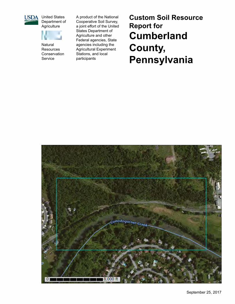
A product of the NationalCooperative Soil Survey,a joint effort of the UnitedStates Department ofAgriculture and otherFederal agencies, Stateagencies including theAgricultural ExperimentStations, and localparticipants
Custom Soil ResourceReport forCumberlandCounty,Pennsylvania
NaturalResourcesConservationService
September 25, 2017
PrefaceSoil surveys contain information that affects land use planning in survey areas.They highlight soil limitations that affect various land uses and provide informationabout the properties of the soils in the survey areas. Soil surveys are designed formany different users, including farmers, ranchers, foresters, agronomists, urbanplanners, community officials, engineers, developers, builders, and home buyers.Also, conservationists, teachers, students, and specialists in recreation, wastedisposal, and pollution control can use the surveys to help them understand,protect, or enhance the environment.
Various land use regulations of Federal, State, and local governments may imposespecial restrictions on land use or land treatment. Soil surveys identify soilproperties that are used in making various land use or land treatment decisions.The information is intended to help the land users identify and reduce the effects ofsoil limitations on various land uses. The landowner or user is responsible foridentifying and complying with existing laws and regulations.
Although soil survey information can be used for general farm, local, and wider areaplanning, onsite investigation is needed to supplement this information in somecases. Examples include soil quality assessments (http://www.nrcs.usda.gov/wps/portal/nrcs/main/soils/health/) and certain conservation and engineeringapplications. For more detailed information, contact your local USDA Service Center(https://offices.sc.egov.usda.gov/locator/app?agency=nrcs) or your NRCS State SoilScientist (http://www.nrcs.usda.gov/wps/portal/nrcs/detail/soils/contactus/?cid=nrcs142p2_053951).
Great differences in soil properties can occur within short distances. Some soils areseasonally wet or subject to flooding. Some are too unstable to be used as afoundation for buildings or roads. Clayey or wet soils are poorly suited to use asseptic tank absorption fields. A high water table makes a soil poorly suited tobasements or underground installations.
The National Cooperative Soil Survey is a joint effort of the United StatesDepartment of Agriculture and other Federal agencies, State agencies including theAgricultural Experiment Stations, and local agencies. The Natural ResourcesConservation Service (NRCS) has leadership for the Federal part of the NationalCooperative Soil Survey.
Information about soils is updated periodically. Updated information is availablethrough the NRCS Web Soil Survey, the site for official soil survey information.
The U.S. Department of Agriculture (USDA) prohibits discrimination in all itsprograms and activities on the basis of race, color, national origin, age, disability,and where applicable, sex, marital status, familial status, parental status, religion,sexual orientation, genetic information, political beliefs, reprisal, or because all or apart of an individual's income is derived from any public assistance program. (Notall prohibited bases apply to all programs.) Persons with disabilities who require
2

alternative means for communication of program information (Braille, large print,audiotape, etc.) should contact USDA's TARGET Center at (202) 720-2600 (voiceand TDD). To file a complaint of discrimination, write to USDA, Director, Office ofCivil Rights, 1400 Independence Avenue, S.W., Washington, D.C. 20250-9410 orcall (800) 795-3272 (voice) or (202) 720-6382 (TDD). USDA is an equal opportunityprovider and employer.
3
ContentsPreface.................................................................................................................... 2How Soil Surveys Are Made..................................................................................5Soil Map.................................................................................................................. 8
Soil Map................................................................................................................9Legend................................................................................................................10Map Unit Legend................................................................................................ 11Map Unit Descriptions.........................................................................................11
Cumberland County, Pennsylvania.................................................................14Aw—Atkins silt loam....................................................................................14BeB—Berks channery silt loam, 3 to 8 percent slopes............................... 15BpB—Blairton silt loam, 3 to 8 percent slopes............................................ 16Mf—Middlebury soils................................................................................... 17MnB—Monongahela silt loam, 3 to 8 percent slopes.................................. 19MnC—Monongahela silt loam, 8 to 15 percent slopes................................20Pt—Pits and quarries.................................................................................. 21Pu—Purdy silt loam.....................................................................................22W—Water....................................................................................................23WeC—Weikert very channery silt loam, 8 to 15 percent slopes..................24WeD—Weikert very channery silt loam, 15 to 25 percent slopes................25WkF—Weikert and Klinesville very shaly silt loams, 25 to 75 percent
slopes....................................................................................................27References............................................................................................................29
4
How Soil Surveys Are MadeSoil surveys are made to provide information about the soils and miscellaneousareas in a specific area. They include a description of the soils and miscellaneousareas and their location on the landscape and tables that show soil properties andlimitations affecting various uses. Soil scientists observed the steepness, length,and shape of the slopes; the general pattern of drainage; the kinds of crops andnative plants; and the kinds of bedrock. They observed and described many soilprofiles. A soil profile is the sequence of natural layers, or horizons, in a soil. Theprofile extends from the surface down into the unconsolidated material in which thesoil formed or from the surface down to bedrock. The unconsolidated material isdevoid of roots and other living organisms and has not been changed by otherbiological activity.
Currently, soils are mapped according to the boundaries of major land resourceareas (MLRAs). MLRAs are geographically associated land resource units thatshare common characteristics related to physiography, geology, climate, waterresources, soils, biological resources, and land uses (USDA, 2006). Soil surveyareas typically consist of parts of one or more MLRA.
The soils and miscellaneous areas in a survey area occur in an orderly pattern thatis related to the geology, landforms, relief, climate, and natural vegetation of thearea. Each kind of soil and miscellaneous area is associated with a particular kindof landform or with a segment of the landform. By observing the soils andmiscellaneous areas in the survey area and relating their position to specificsegments of the landform, a soil scientist develops a concept, or model, of how theywere formed. Thus, during mapping, this model enables the soil scientist to predictwith a considerable degree of accuracy the kind of soil or miscellaneous area at aspecific location on the landscape.
Commonly, individual soils on the landscape merge into one another as theircharacteristics gradually change. To construct an accurate soil map, however, soilscientists must determine the boundaries between the soils. They can observe onlya limited number of soil profiles. Nevertheless, these observations, supplementedby an understanding of the soil-vegetation-landscape relationship, are sufficient toverify predictions of the kinds of soil in an area and to determine the boundaries.
Soil scientists recorded the characteristics of the soil profiles that they studied. Theynoted soil color, texture, size and shape of soil aggregates, kind and amount of rockfragments, distribution of plant roots, reaction, and other features that enable themto identify soils. After describing the soils in the survey area and determining theirproperties, the soil scientists assigned the soils to taxonomic classes (units).Taxonomic classes are concepts. Each taxonomic class has a set of soilcharacteristics with precisely defined limits. The classes are used as a basis forcomparison to classify soils systematically. Soil taxonomy, the system of taxonomicclassification used in the United States, is based mainly on the kind and characterof soil properties and the arrangement of horizons within the profile. After the soil
5
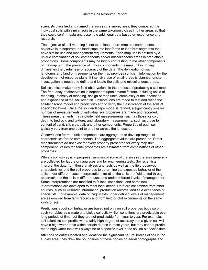
scientists classified and named the soils in the survey area, they compared theindividual soils with similar soils in the same taxonomic class in other areas so thatthey could confirm data and assemble additional data based on experience andresearch.
The objective of soil mapping is not to delineate pure map unit components; theobjective is to separate the landscape into landforms or landform segments thathave similar use and management requirements. Each map unit is defined by aunique combination of soil components and/or miscellaneous areas in predictableproportions. Some components may be highly contrasting to the other componentsof the map unit. The presence of minor components in a map unit in no waydiminishes the usefulness or accuracy of the data. The delineation of suchlandforms and landform segments on the map provides sufficient information for thedevelopment of resource plans. If intensive use of small areas is planned, onsiteinvestigation is needed to define and locate the soils and miscellaneous areas.
Soil scientists make many field observations in the process of producing a soil map.The frequency of observation is dependent upon several factors, including scale ofmapping, intensity of mapping, design of map units, complexity of the landscape,and experience of the soil scientist. Observations are made to test and refine thesoil-landscape model and predictions and to verify the classification of the soils atspecific locations. Once the soil-landscape model is refined, a significantly smallernumber of measurements of individual soil properties are made and recorded.These measurements may include field measurements, such as those for color,depth to bedrock, and texture, and laboratory measurements, such as those forcontent of sand, silt, clay, salt, and other components. Properties of each soiltypically vary from one point to another across the landscape.
Observations for map unit components are aggregated to develop ranges ofcharacteristics for the components. The aggregated values are presented. Directmeasurements do not exist for every property presented for every map unitcomponent. Values for some properties are estimated from combinations of otherproperties.
While a soil survey is in progress, samples of some of the soils in the area generallyare collected for laboratory analyses and for engineering tests. Soil scientistsinterpret the data from these analyses and tests as well as the field-observedcharacteristics and the soil properties to determine the expected behavior of thesoils under different uses. Interpretations for all of the soils are field tested throughobservation of the soils in different uses and under different levels of management.Some interpretations are modified to fit local conditions, and some newinterpretations are developed to meet local needs. Data are assembled from othersources, such as research information, production records, and field experience ofspecialists. For example, data on crop yields under defined levels of managementare assembled from farm records and from field or plot experiments on the samekinds of soil.
Predictions about soil behavior are based not only on soil properties but also onsuch variables as climate and biological activity. Soil conditions are predictable overlong periods of time, but they are not predictable from year to year. For example,soil scientists can predict with a fairly high degree of accuracy that a given soil willhave a high water table within certain depths in most years, but they cannot predictthat a high water table will always be at a specific level in the soil on a specific date.
After soil scientists located and identified the significant natural bodies of soil in thesurvey area, they drew the boundaries of these bodies on aerial photographs and
Custom Soil Resource Report
6

identified each as a specific map unit. Aerial photographs show trees, buildings,fields, roads, and rivers, all of which help in locating boundaries accurately.
Custom Soil Resource Report
7
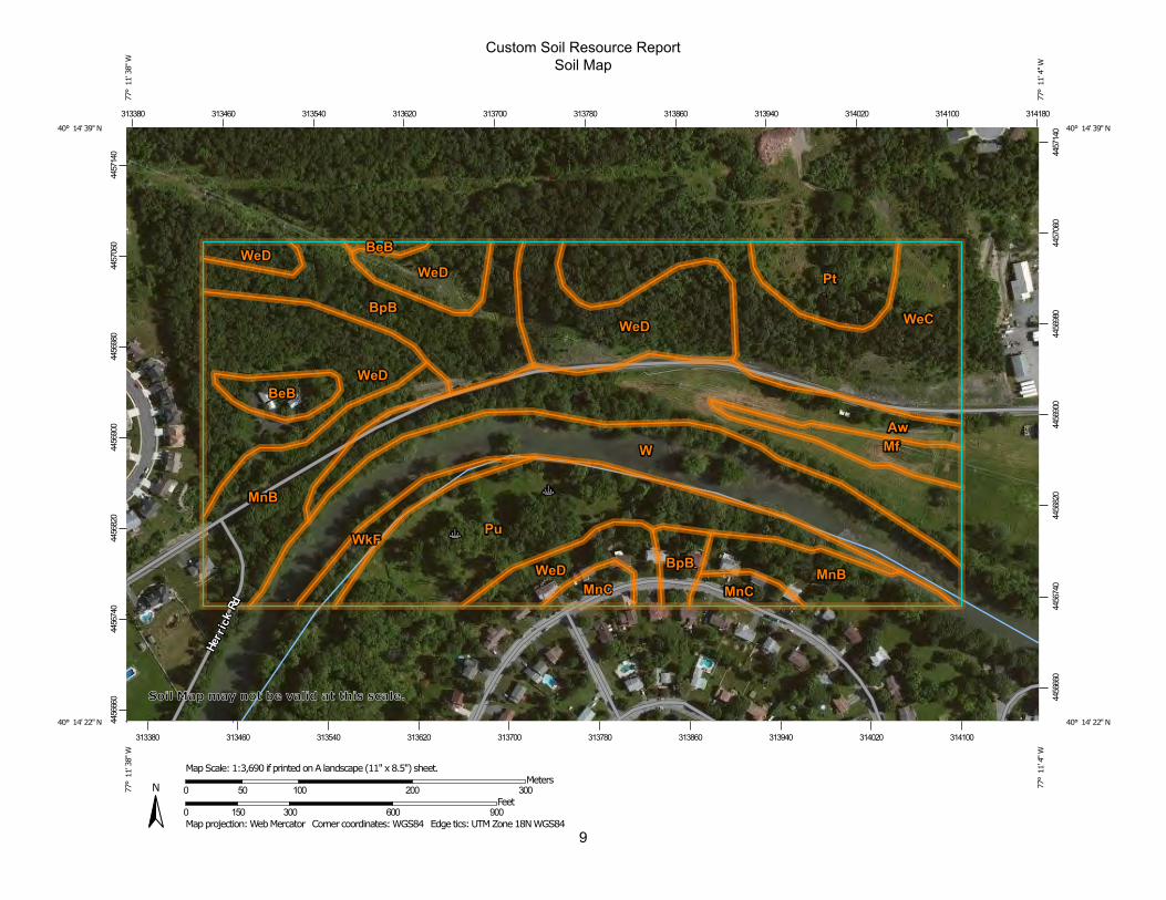
Soil MapThe soil map section includes the soil map for the defined area of interest, a list ofsoil map units on the map and extent of each map unit, and cartographic symbolsdisplayed on the map. Also presented are various metadata about data used toproduce the map, and a description of each soil map unit.
8
9
Custom Soil Resource ReportSoil Map
4456
660
4456
740
4456
820
4456
900
4456
980
4457
060
4457
140
4456
660
4456
740
4456
820
4456
900
4456
980
4457
060
4457
140
313380 313460 313540 313620 313700 313780 313860 313940 314020 314100 314180
313380 313460 313540 313620 313700 313780 313860 313940 314020 314100
40° 14' 39'' N77
° 1
1' 3
8'' W
40° 14' 39'' N
77° 1
1' 4
'' W
40° 14' 22'' N
77° 1
1' 3
8'' W
40° 14' 22'' N
77° 1
1' 4
'' W
N
Map projection: Web Mercator Corner coordinates: WGS84 Edge tics: UTM Zone 18N WGS840 150 300 600 900
Feet0 50 100 200 300
MetersMap Scale: 1:3,690 if printed on A landscape (11" x 8.5") sheet.
Soil Map may not be valid at this scale.
MAP LEGEND MAP INFORMATION
Area of Interest (AOI)Area of Interest (AOI)
SoilsSoil Map Unit Polygons
Soil Map Unit Lines
Soil Map Unit Points
Special Point FeaturesBlowout
Borrow Pit
Clay Spot
Closed Depression
Gravel Pit
Gravelly Spot
Landfill
Lava Flow
Marsh or swamp
Mine or Quarry
Miscellaneous Water
Perennial Water
Rock Outcrop
Saline Spot
Sandy Spot
Severely Eroded Spot
Sinkhole
Slide or Slip
Sodic Spot
Spoil Area
Stony Spot
Very Stony Spot
Wet Spot
Other
Special Line Features
Water FeaturesStreams and Canals
TransportationRails
Interstate Highways
US Routes
Major Roads
Local Roads
BackgroundAerial Photography
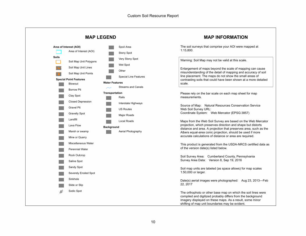
The soil surveys that comprise your AOI were mapped at1:15,800.
Warning: Soil Map may not be valid at this scale.
Enlargement of maps beyond the scale of mapping can causemisunderstanding of the detail of mapping and accuracy of soilline placement. The maps do not show the small areas ofcontrasting soils that could have been shown at a more detailedscale.
Please rely on the bar scale on each map sheet for mapmeasurements.
Source of Map: Natural Resources Conservation ServiceWeb Soil Survey URL:Coordinate System: Web Mercator (EPSG:3857)
Maps from the Web Soil Survey are based on the Web Mercatorprojection, which preserves direction and shape but distortsdistance and area. A projection that preserves area, such as theAlbers equal-area conic projection, should be used if moreaccurate calculations of distance or area are required.
This product is generated from the USDA-NRCS certified data asof the version date(s) listed below.
Soil Survey Area: Cumberland County, PennsylvaniaSurvey Area Data: Version 8, Sep 19, 2016
Soil map units are labeled (as space allows) for map scales1:50,000 or larger.
Date(s) aerial images were photographed: Aug 23, 2013—Feb22, 2017
The orthophoto or other base map on which the soil lines werecompiled and digitized probably differs from the backgroundimagery displayed on these maps. As a result, some minorshifting of map unit boundaries may be evident.
Custom Soil Resource Report
10
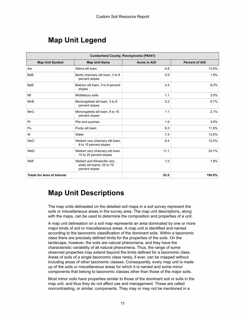
Map Unit Legend
Cumberland County, Pennsylvania (PA041)
Map Unit Symbol Map Unit Name Acres in AOI Percent of AOI
Aw Atkins silt loam 6.8 12.6%
BeB Berks channery silt loam, 3 to 8percent slopes
0.9 1.8%
BpB Blairton silt loam, 3 to 8 percentslopes
4.4 8.2%
Mf Middlebury soils 1.1 2.0%
MnB Monongahela silt loam, 3 to 8percent slopes
5.2 9.7%
MnC Monongahela silt loam, 8 to 15percent slopes
1.1 2.1%
Pt Pits and quarries 1.9 3.6%
Pu Purdy silt loam 6.3 11.8%
W Water 7.4 13.8%
WeC Weikert very channery silt loam,8 to 15 percent slopes
6.4 12.0%
WeD Weikert very channery silt loam,15 to 25 percent slopes
11.1 20.7%
WkF Weikert and Klinesville veryshaly silt loams, 25 to 75percent slopes
1.0 1.8%
Totals for Area of Interest 53.5 100.0%
Map Unit DescriptionsThe map units delineated on the detailed soil maps in a soil survey represent thesoils or miscellaneous areas in the survey area. The map unit descriptions, alongwith the maps, can be used to determine the composition and properties of a unit.
A map unit delineation on a soil map represents an area dominated by one or moremajor kinds of soil or miscellaneous areas. A map unit is identified and namedaccording to the taxonomic classification of the dominant soils. Within a taxonomicclass there are precisely defined limits for the properties of the soils. On thelandscape, however, the soils are natural phenomena, and they have thecharacteristic variability of all natural phenomena. Thus, the range of someobserved properties may extend beyond the limits defined for a taxonomic class.Areas of soils of a single taxonomic class rarely, if ever, can be mapped withoutincluding areas of other taxonomic classes. Consequently, every map unit is madeup of the soils or miscellaneous areas for which it is named and some minorcomponents that belong to taxonomic classes other than those of the major soils.
Most minor soils have properties similar to those of the dominant soil or soils in themap unit, and thus they do not affect use and management. These are callednoncontrasting, or similar, components. They may or may not be mentioned in a
Custom Soil Resource Report
11
particular map unit description. Other minor components, however, have propertiesand behavioral characteristics divergent enough to affect use or to require differentmanagement. These are called contrasting, or dissimilar, components. Theygenerally are in small areas and could not be mapped separately because of thescale used. Some small areas of strongly contrasting soils or miscellaneous areasare identified by a special symbol on the maps. If included in the database for agiven area, the contrasting minor components are identified in the map unitdescriptions along with some characteristics of each. A few areas of minorcomponents may not have been observed, and consequently they are notmentioned in the descriptions, especially where the pattern was so complex that itwas impractical to make enough observations to identify all the soils andmiscellaneous areas on the landscape.
The presence of minor components in a map unit in no way diminishes theusefulness or accuracy of the data. The objective of mapping is not to delineatepure taxonomic classes but rather to separate the landscape into landforms orlandform segments that have similar use and management requirements. Thedelineation of such segments on the map provides sufficient information for thedevelopment of resource plans. If intensive use of small areas is planned, however,onsite investigation is needed to define and locate the soils and miscellaneousareas.
An identifying symbol precedes the map unit name in the map unit descriptions.Each description includes general facts about the unit and gives important soilproperties and qualities.
Soils that have profiles that are almost alike make up a soil series. Except fordifferences in texture of the surface layer, all the soils of a series have majorhorizons that are similar in composition, thickness, and arrangement.
Soils of one series can differ in texture of the surface layer, slope, stoniness,salinity, degree of erosion, and other characteristics that affect their use. On thebasis of such differences, a soil series is divided into soil phases. Most of the areasshown on the detailed soil maps are phases of soil series. The name of a soil phasecommonly indicates a feature that affects use or management. For example, Alphasilt loam, 0 to 2 percent slopes, is a phase of the Alpha series.
Some map units are made up of two or more major soils or miscellaneous areas.These map units are complexes, associations, or undifferentiated groups.
A complex consists of two or more soils or miscellaneous areas in such an intricatepattern or in such small areas that they cannot be shown separately on the maps.The pattern and proportion of the soils or miscellaneous areas are somewhat similarin all areas. Alpha-Beta complex, 0 to 6 percent slopes, is an example.
An association is made up of two or more geographically associated soils ormiscellaneous areas that are shown as one unit on the maps. Because of presentor anticipated uses of the map units in the survey area, it was not consideredpractical or necessary to map the soils or miscellaneous areas separately. Thepattern and relative proportion of the soils or miscellaneous areas are somewhatsimilar. Alpha-Beta association, 0 to 2 percent slopes, is an example.
An undifferentiated group is made up of two or more soils or miscellaneous areasthat could be mapped individually but are mapped as one unit because similarinterpretations can be made for use and management. The pattern and proportionof the soils or miscellaneous areas in a mapped area are not uniform. An area canbe made up of only one of the major soils or miscellaneous areas, or it can be madeup of all of them. Alpha and Beta soils, 0 to 2 percent slopes, is an example.
Custom Soil Resource Report
12

Some surveys include miscellaneous areas. Such areas have little or no soilmaterial and support little or no vegetation. Rock outcrop is an example.
Custom Soil Resource Report
13
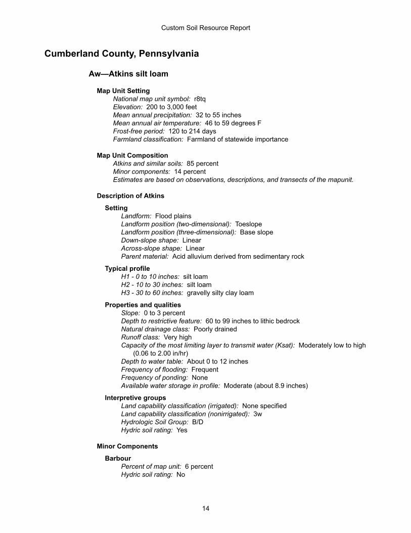
Cumberland County, Pennsylvania
Aw—Atkins silt loam
Map Unit SettingNational map unit symbol: r8tqElevation: 200 to 3,000 feetMean annual precipitation: 32 to 55 inchesMean annual air temperature: 46 to 59 degrees FFrost-free period: 120 to 214 daysFarmland classification: Farmland of statewide importance
Map Unit CompositionAtkins and similar soils: 85 percentMinor components: 14 percentEstimates are based on observations, descriptions, and transects of the mapunit.
Description of Atkins
SettingLandform: Flood plainsLandform position (two-dimensional): ToeslopeLandform position (three-dimensional): Base slopeDown-slope shape: LinearAcross-slope shape: LinearParent material: Acid alluvium derived from sedimentary rock
Typical profileH1 - 0 to 10 inches: silt loamH2 - 10 to 30 inches: silt loamH3 - 30 to 60 inches: gravelly silty clay loam
Properties and qualitiesSlope: 0 to 3 percentDepth to restrictive feature: 60 to 99 inches to lithic bedrockNatural drainage class: Poorly drainedRunoff class: Very highCapacity of the most limiting layer to transmit water (Ksat): Moderately low to high
(0.06 to 2.00 in/hr)Depth to water table: About 0 to 12 inchesFrequency of flooding: FrequentFrequency of ponding: NoneAvailable water storage in profile: Moderate (about 8.9 inches)
Interpretive groupsLand capability classification (irrigated): None specifiedLand capability classification (nonirrigated): 3wHydrologic Soil Group: B/DHydric soil rating: Yes
Minor Components
BarbourPercent of map unit: 6 percentHydric soil rating: No
Custom Soil Resource Report
14
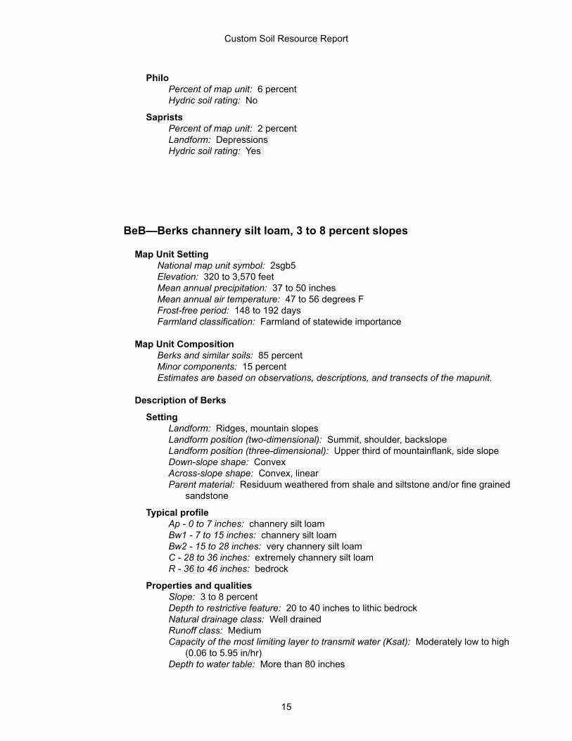
PhiloPercent of map unit: 6 percentHydric soil rating: No
SapristsPercent of map unit: 2 percentLandform: DepressionsHydric soil rating: Yes
BeB—Berks channery silt loam, 3 to 8 percent slopes
Map Unit SettingNational map unit symbol: 2sgb5Elevation: 320 to 3,570 feetMean annual precipitation: 37 to 50 inchesMean annual air temperature: 47 to 56 degrees FFrost-free period: 148 to 192 daysFarmland classification: Farmland of statewide importance
Map Unit CompositionBerks and similar soils: 85 percentMinor components: 15 percentEstimates are based on observations, descriptions, and transects of the mapunit.
Description of Berks
SettingLandform: Ridges, mountain slopesLandform position (two-dimensional): Summit, shoulder, backslopeLandform position (three-dimensional): Upper third of mountainflank, side slopeDown-slope shape: ConvexAcross-slope shape: Convex, linearParent material: Residuum weathered from shale and siltstone and/or fine grained
sandstone
Typical profileAp - 0 to 7 inches: channery silt loamBw1 - 7 to 15 inches: channery silt loamBw2 - 15 to 28 inches: very channery silt loamC - 28 to 36 inches: extremely channery silt loamR - 36 to 46 inches: bedrock
Properties and qualitiesSlope: 3 to 8 percentDepth to restrictive feature: 20 to 40 inches to lithic bedrockNatural drainage class: Well drainedRunoff class: MediumCapacity of the most limiting layer to transmit water (Ksat): Moderately low to high
(0.06 to 5.95 in/hr)Depth to water table: More than 80 inches
Custom Soil Resource Report
15
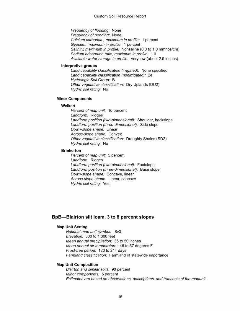
Frequency of flooding: NoneFrequency of ponding: NoneCalcium carbonate, maximum in profile: 1 percentGypsum, maximum in profile: 1 percentSalinity, maximum in profile: Nonsaline (0.0 to 1.0 mmhos/cm)Sodium adsorption ratio, maximum in profile: 1.0Available water storage in profile: Very low (about 2.9 inches)
Interpretive groupsLand capability classification (irrigated): None specifiedLand capability classification (nonirrigated): 2eHydrologic Soil Group: BOther vegetative classification: Dry Uplands (DU2)Hydric soil rating: No
Minor Components
WeikertPercent of map unit: 10 percentLandform: RidgesLandform position (two-dimensional): Shoulder, backslopeLandform position (three-dimensional): Side slopeDown-slope shape: LinearAcross-slope shape: ConvexOther vegetative classification: Droughty Shales (SD2)Hydric soil rating: No
BrinkertonPercent of map unit: 5 percentLandform: RidgesLandform position (two-dimensional): FootslopeLandform position (three-dimensional): Base slopeDown-slope shape: Concave, linearAcross-slope shape: Linear, concaveHydric soil rating: Yes
BpB—Blairton silt loam, 3 to 8 percent slopes
Map Unit SettingNational map unit symbol: r8v3Elevation: 300 to 1,300 feetMean annual precipitation: 35 to 50 inchesMean annual air temperature: 46 to 57 degrees FFrost-free period: 120 to 214 daysFarmland classification: Farmland of statewide importance
Map Unit CompositionBlairton and similar soils: 90 percentMinor components: 5 percentEstimates are based on observations, descriptions, and transects of the mapunit.
Custom Soil Resource Report
16
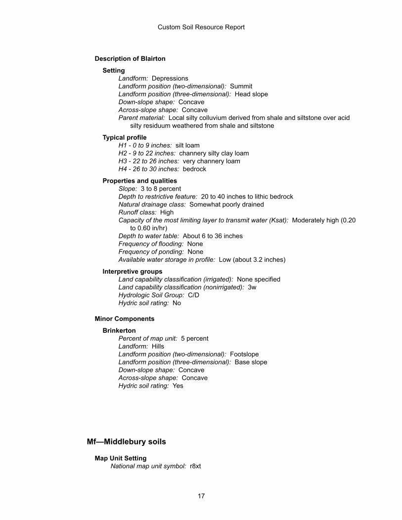
Description of Blairton
SettingLandform: DepressionsLandform position (two-dimensional): SummitLandform position (three-dimensional): Head slopeDown-slope shape: ConcaveAcross-slope shape: ConcaveParent material: Local silty colluvium derived from shale and siltstone over acid
silty residuum weathered from shale and siltstone
Typical profileH1 - 0 to 9 inches: silt loamH2 - 9 to 22 inches: channery silty clay loamH3 - 22 to 26 inches: very channery loamH4 - 26 to 30 inches: bedrock
Properties and qualitiesSlope: 3 to 8 percentDepth to restrictive feature: 20 to 40 inches to lithic bedrockNatural drainage class: Somewhat poorly drainedRunoff class: HighCapacity of the most limiting layer to transmit water (Ksat): Moderately high (0.20
to 0.60 in/hr)Depth to water table: About 6 to 36 inchesFrequency of flooding: NoneFrequency of ponding: NoneAvailable water storage in profile: Low (about 3.2 inches)
Interpretive groupsLand capability classification (irrigated): None specifiedLand capability classification (nonirrigated): 3wHydrologic Soil Group: C/DHydric soil rating: No
Minor Components
BrinkertonPercent of map unit: 5 percentLandform: HillsLandform position (two-dimensional): FootslopeLandform position (three-dimensional): Base slopeDown-slope shape: ConcaveAcross-slope shape: ConcaveHydric soil rating: Yes
Mf—Middlebury soils
Map Unit SettingNational map unit symbol: r8xt
Custom Soil Resource Report
17
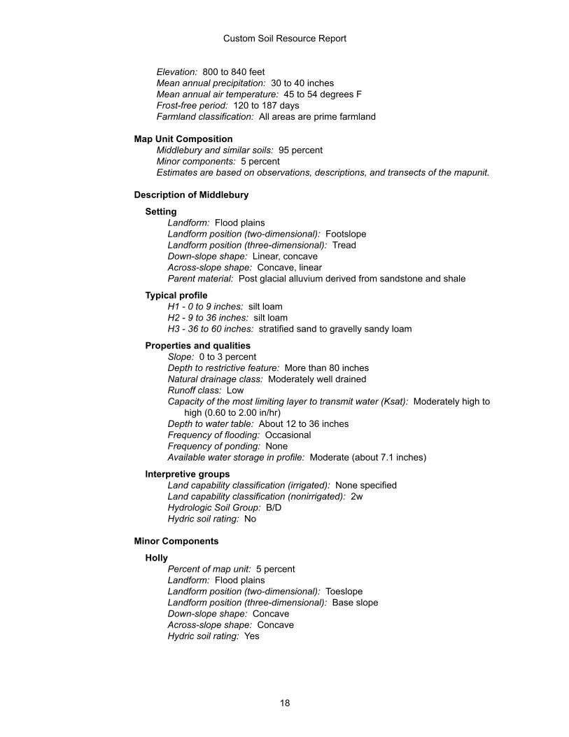
Elevation: 800 to 840 feetMean annual precipitation: 30 to 40 inchesMean annual air temperature: 45 to 54 degrees FFrost-free period: 120 to 187 daysFarmland classification: All areas are prime farmland
Map Unit CompositionMiddlebury and similar soils: 95 percentMinor components: 5 percentEstimates are based on observations, descriptions, and transects of the mapunit.
Description of Middlebury
SettingLandform: Flood plainsLandform position (two-dimensional): FootslopeLandform position (three-dimensional): TreadDown-slope shape: Linear, concaveAcross-slope shape: Concave, linearParent material: Post glacial alluvium derived from sandstone and shale
Typical profileH1 - 0 to 9 inches: silt loamH2 - 9 to 36 inches: silt loamH3 - 36 to 60 inches: stratified sand to gravelly sandy loam
Properties and qualitiesSlope: 0 to 3 percentDepth to restrictive feature: More than 80 inchesNatural drainage class: Moderately well drainedRunoff class: LowCapacity of the most limiting layer to transmit water (Ksat): Moderately high to
high (0.60 to 2.00 in/hr)Depth to water table: About 12 to 36 inchesFrequency of flooding: OccasionalFrequency of ponding: NoneAvailable water storage in profile: Moderate (about 7.1 inches)
Interpretive groupsLand capability classification (irrigated): None specifiedLand capability classification (nonirrigated): 2wHydrologic Soil Group: B/DHydric soil rating: No
Minor Components
HollyPercent of map unit: 5 percentLandform: Flood plainsLandform position (two-dimensional): ToeslopeLandform position (three-dimensional): Base slopeDown-slope shape: ConcaveAcross-slope shape: ConcaveHydric soil rating: Yes
Custom Soil Resource Report
18
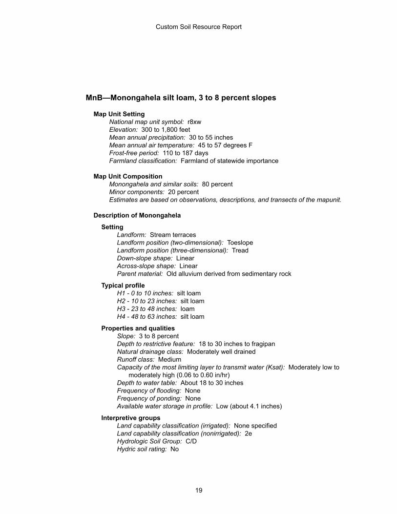
MnB—Monongahela silt loam, 3 to 8 percent slopes
Map Unit SettingNational map unit symbol: r8xwElevation: 300 to 1,800 feetMean annual precipitation: 30 to 55 inchesMean annual air temperature: 45 to 57 degrees FFrost-free period: 110 to 187 daysFarmland classification: Farmland of statewide importance
Map Unit CompositionMonongahela and similar soils: 80 percentMinor components: 20 percentEstimates are based on observations, descriptions, and transects of the mapunit.
Description of Monongahela
SettingLandform: Stream terracesLandform position (two-dimensional): ToeslopeLandform position (three-dimensional): TreadDown-slope shape: LinearAcross-slope shape: LinearParent material: Old alluvium derived from sedimentary rock
Typical profileH1 - 0 to 10 inches: silt loamH2 - 10 to 23 inches: silt loamH3 - 23 to 48 inches: loamH4 - 48 to 63 inches: silt loam
Properties and qualitiesSlope: 3 to 8 percentDepth to restrictive feature: 18 to 30 inches to fragipanNatural drainage class: Moderately well drainedRunoff class: MediumCapacity of the most limiting layer to transmit water (Ksat): Moderately low to
moderately high (0.06 to 0.60 in/hr)Depth to water table: About 18 to 30 inchesFrequency of flooding: NoneFrequency of ponding: NoneAvailable water storage in profile: Low (about 4.1 inches)
Interpretive groupsLand capability classification (irrigated): None specifiedLand capability classification (nonirrigated): 2eHydrologic Soil Group: C/DHydric soil rating: No
Custom Soil Resource Report
19
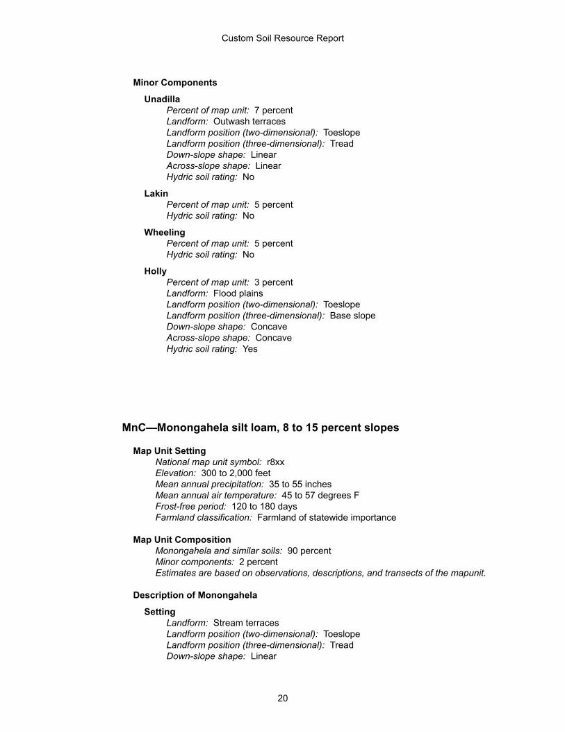
Minor Components
UnadillaPercent of map unit: 7 percentLandform: Outwash terracesLandform position (two-dimensional): ToeslopeLandform position (three-dimensional): TreadDown-slope shape: LinearAcross-slope shape: LinearHydric soil rating: No
LakinPercent of map unit: 5 percentHydric soil rating: No
WheelingPercent of map unit: 5 percentHydric soil rating: No
HollyPercent of map unit: 3 percentLandform: Flood plainsLandform position (two-dimensional): ToeslopeLandform position (three-dimensional): Base slopeDown-slope shape: ConcaveAcross-slope shape: ConcaveHydric soil rating: Yes
MnC—Monongahela silt loam, 8 to 15 percent slopes
Map Unit SettingNational map unit symbol: r8xxElevation: 300 to 2,000 feetMean annual precipitation: 35 to 55 inchesMean annual air temperature: 45 to 57 degrees FFrost-free period: 120 to 180 daysFarmland classification: Farmland of statewide importance
Map Unit CompositionMonongahela and similar soils: 90 percentMinor components: 2 percentEstimates are based on observations, descriptions, and transects of the mapunit.
Description of Monongahela
SettingLandform: Stream terracesLandform position (two-dimensional): ToeslopeLandform position (three-dimensional): TreadDown-slope shape: Linear
Custom Soil Resource Report
20
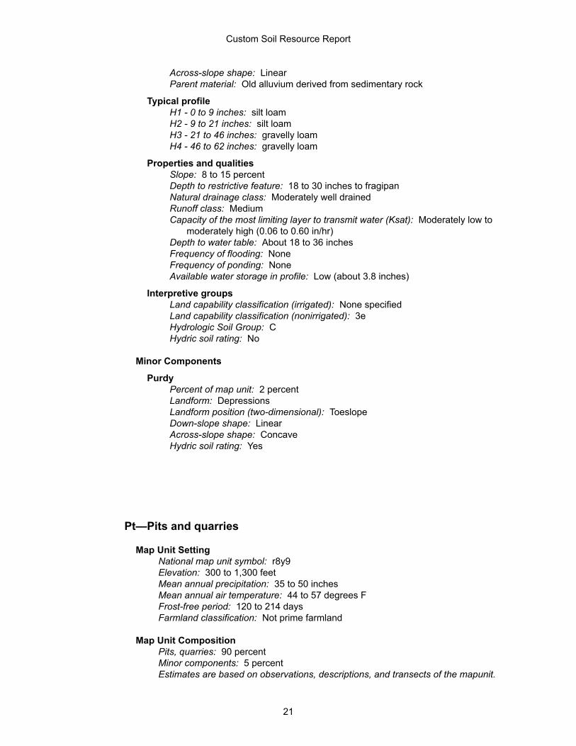
Across-slope shape: LinearParent material: Old alluvium derived from sedimentary rock
Typical profileH1 - 0 to 9 inches: silt loamH2 - 9 to 21 inches: silt loamH3 - 21 to 46 inches: gravelly loamH4 - 46 to 62 inches: gravelly loam
Properties and qualitiesSlope: 8 to 15 percentDepth to restrictive feature: 18 to 30 inches to fragipanNatural drainage class: Moderately well drainedRunoff class: MediumCapacity of the most limiting layer to transmit water (Ksat): Moderately low to
moderately high (0.06 to 0.60 in/hr)Depth to water table: About 18 to 36 inchesFrequency of flooding: NoneFrequency of ponding: NoneAvailable water storage in profile: Low (about 3.8 inches)
Interpretive groupsLand capability classification (irrigated): None specifiedLand capability classification (nonirrigated): 3eHydrologic Soil Group: CHydric soil rating: No
Minor Components
PurdyPercent of map unit: 2 percentLandform: DepressionsLandform position (two-dimensional): ToeslopeDown-slope shape: LinearAcross-slope shape: ConcaveHydric soil rating: Yes
Pt—Pits and quarries
Map Unit SettingNational map unit symbol: r8y9Elevation: 300 to 1,300 feetMean annual precipitation: 35 to 50 inchesMean annual air temperature: 44 to 57 degrees FFrost-free period: 120 to 214 daysFarmland classification: Not prime farmland
Map Unit CompositionPits, quarries: 90 percentMinor components: 5 percentEstimates are based on observations, descriptions, and transects of the mapunit.
Custom Soil Resource Report
21
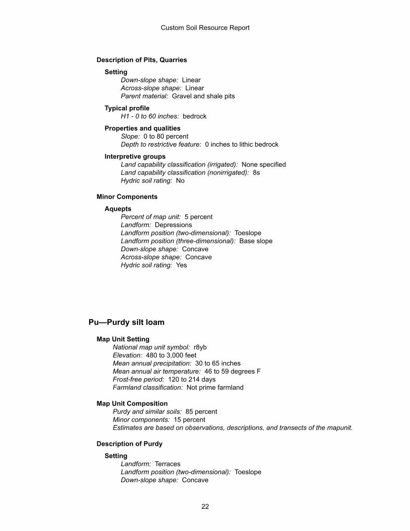
Description of Pits, Quarries
SettingDown-slope shape: LinearAcross-slope shape: LinearParent material: Gravel and shale pits
Typical profileH1 - 0 to 60 inches: bedrock
Properties and qualitiesSlope: 0 to 80 percentDepth to restrictive feature: 0 inches to lithic bedrock
Interpretive groupsLand capability classification (irrigated): None specifiedLand capability classification (nonirrigated): 8sHydric soil rating: No
Minor Components
AqueptsPercent of map unit: 5 percentLandform: DepressionsLandform position (two-dimensional): ToeslopeLandform position (three-dimensional): Base slopeDown-slope shape: ConcaveAcross-slope shape: ConcaveHydric soil rating: Yes
Pu—Purdy silt loam
Map Unit SettingNational map unit symbol: r8ybElevation: 480 to 3,000 feetMean annual precipitation: 30 to 65 inchesMean annual air temperature: 46 to 59 degrees FFrost-free period: 120 to 214 daysFarmland classification: Not prime farmland
Map Unit CompositionPurdy and similar soils: 85 percentMinor components: 15 percentEstimates are based on observations, descriptions, and transects of the mapunit.
Description of Purdy
SettingLandform: TerracesLandform position (two-dimensional): ToeslopeDown-slope shape: Concave
Custom Soil Resource Report
22
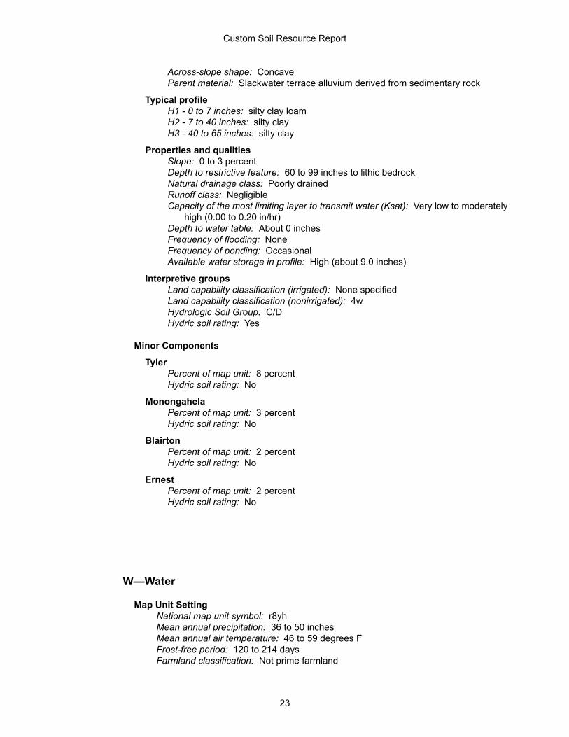
Across-slope shape: ConcaveParent material: Slackwater terrace alluvium derived from sedimentary rock
Typical profileH1 - 0 to 7 inches: silty clay loamH2 - 7 to 40 inches: silty clayH3 - 40 to 65 inches: silty clay
Properties and qualitiesSlope: 0 to 3 percentDepth to restrictive feature: 60 to 99 inches to lithic bedrockNatural drainage class: Poorly drainedRunoff class: NegligibleCapacity of the most limiting layer to transmit water (Ksat): Very low to moderately
high (0.00 to 0.20 in/hr)Depth to water table: About 0 inchesFrequency of flooding: NoneFrequency of ponding: OccasionalAvailable water storage in profile: High (about 9.0 inches)
Interpretive groupsLand capability classification (irrigated): None specifiedLand capability classification (nonirrigated): 4wHydrologic Soil Group: C/DHydric soil rating: Yes
Minor Components
TylerPercent of map unit: 8 percentHydric soil rating: No
MonongahelaPercent of map unit: 3 percentHydric soil rating: No
BlairtonPercent of map unit: 2 percentHydric soil rating: No
ErnestPercent of map unit: 2 percentHydric soil rating: No
W—Water
Map Unit SettingNational map unit symbol: r8yhMean annual precipitation: 36 to 50 inchesMean annual air temperature: 46 to 59 degrees FFrost-free period: 120 to 214 daysFarmland classification: Not prime farmland
Custom Soil Resource Report
23
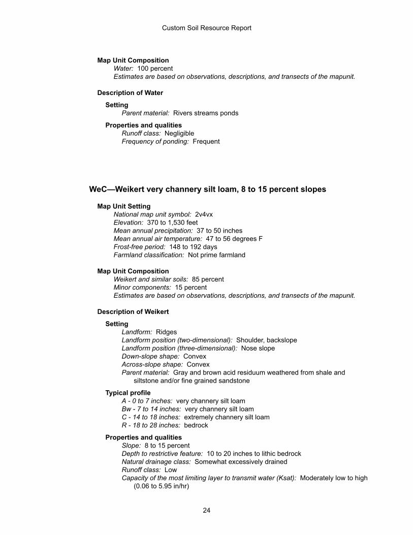
Map Unit CompositionWater: 100 percentEstimates are based on observations, descriptions, and transects of the mapunit.
Description of Water
SettingParent material: Rivers streams ponds
Properties and qualitiesRunoff class: NegligibleFrequency of ponding: Frequent
WeC—Weikert very channery silt loam, 8 to 15 percent slopes
Map Unit SettingNational map unit symbol: 2v4vxElevation: 370 to 1,530 feetMean annual precipitation: 37 to 50 inchesMean annual air temperature: 47 to 56 degrees FFrost-free period: 148 to 192 daysFarmland classification: Not prime farmland
Map Unit CompositionWeikert and similar soils: 85 percentMinor components: 15 percentEstimates are based on observations, descriptions, and transects of the mapunit.
Description of Weikert
SettingLandform: RidgesLandform position (two-dimensional): Shoulder, backslopeLandform position (three-dimensional): Nose slopeDown-slope shape: ConvexAcross-slope shape: ConvexParent material: Gray and brown acid residuum weathered from shale and
siltstone and/or fine grained sandstone
Typical profileA - 0 to 7 inches: very channery silt loamBw - 7 to 14 inches: very channery silt loamC - 14 to 18 inches: extremely channery silt loamR - 18 to 28 inches: bedrock
Properties and qualitiesSlope: 8 to 15 percentDepth to restrictive feature: 10 to 20 inches to lithic bedrockNatural drainage class: Somewhat excessively drainedRunoff class: LowCapacity of the most limiting layer to transmit water (Ksat): Moderately low to high
(0.06 to 5.95 in/hr)
Custom Soil Resource Report
24
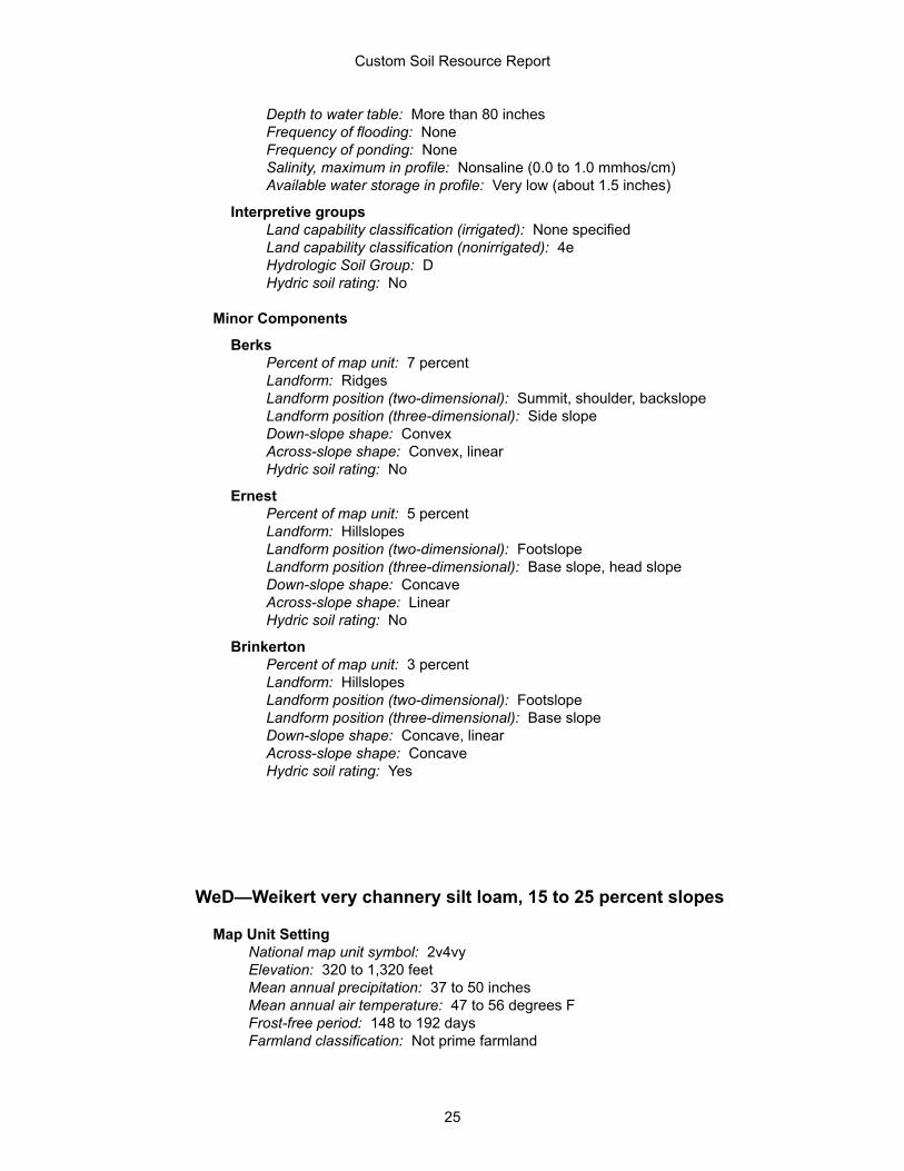
Depth to water table: More than 80 inchesFrequency of flooding: NoneFrequency of ponding: NoneSalinity, maximum in profile: Nonsaline (0.0 to 1.0 mmhos/cm)Available water storage in profile: Very low (about 1.5 inches)
Interpretive groupsLand capability classification (irrigated): None specifiedLand capability classification (nonirrigated): 4eHydrologic Soil Group: DHydric soil rating: No
Minor Components
BerksPercent of map unit: 7 percentLandform: RidgesLandform position (two-dimensional): Summit, shoulder, backslopeLandform position (three-dimensional): Side slopeDown-slope shape: ConvexAcross-slope shape: Convex, linearHydric soil rating: No
ErnestPercent of map unit: 5 percentLandform: HillslopesLandform position (two-dimensional): FootslopeLandform position (three-dimensional): Base slope, head slopeDown-slope shape: ConcaveAcross-slope shape: LinearHydric soil rating: No
BrinkertonPercent of map unit: 3 percentLandform: HillslopesLandform position (two-dimensional): FootslopeLandform position (three-dimensional): Base slopeDown-slope shape: Concave, linearAcross-slope shape: ConcaveHydric soil rating: Yes
WeD—Weikert very channery silt loam, 15 to 25 percent slopes
Map Unit SettingNational map unit symbol: 2v4vyElevation: 320 to 1,320 feetMean annual precipitation: 37 to 50 inchesMean annual air temperature: 47 to 56 degrees FFrost-free period: 148 to 192 daysFarmland classification: Not prime farmland
Custom Soil Resource Report
25
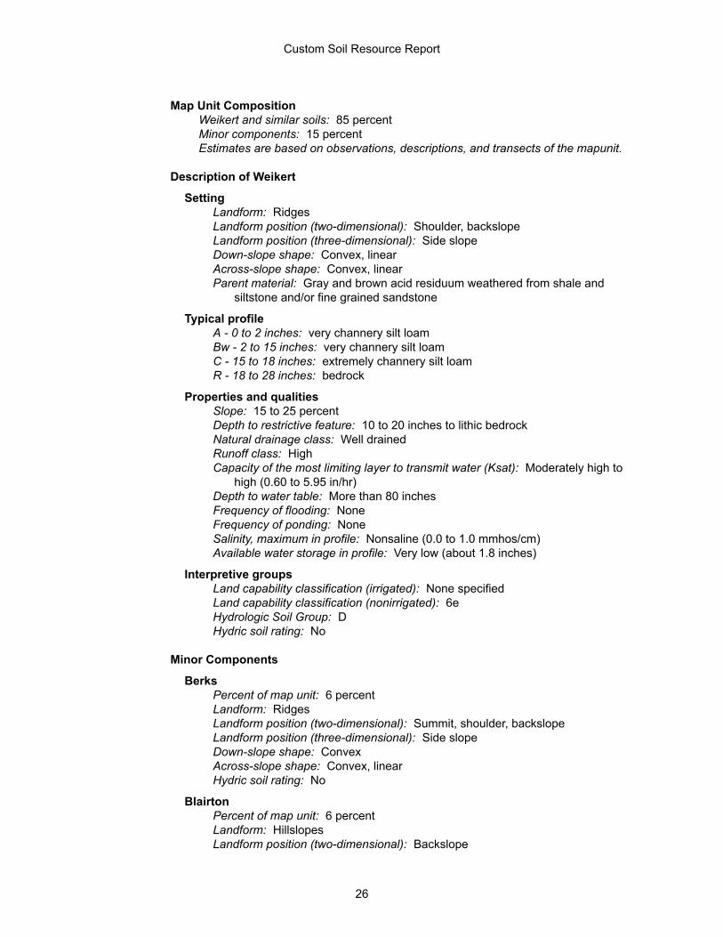
Map Unit CompositionWeikert and similar soils: 85 percentMinor components: 15 percentEstimates are based on observations, descriptions, and transects of the mapunit.
Description of Weikert
SettingLandform: RidgesLandform position (two-dimensional): Shoulder, backslopeLandform position (three-dimensional): Side slopeDown-slope shape: Convex, linearAcross-slope shape: Convex, linearParent material: Gray and brown acid residuum weathered from shale and
siltstone and/or fine grained sandstone
Typical profileA - 0 to 2 inches: very channery silt loamBw - 2 to 15 inches: very channery silt loamC - 15 to 18 inches: extremely channery silt loamR - 18 to 28 inches: bedrock
Properties and qualitiesSlope: 15 to 25 percentDepth to restrictive feature: 10 to 20 inches to lithic bedrockNatural drainage class: Well drainedRunoff class: HighCapacity of the most limiting layer to transmit water (Ksat): Moderately high to
high (0.60 to 5.95 in/hr)Depth to water table: More than 80 inchesFrequency of flooding: NoneFrequency of ponding: NoneSalinity, maximum in profile: Nonsaline (0.0 to 1.0 mmhos/cm)Available water storage in profile: Very low (about 1.8 inches)
Interpretive groupsLand capability classification (irrigated): None specifiedLand capability classification (nonirrigated): 6eHydrologic Soil Group: DHydric soil rating: No
Minor Components
BerksPercent of map unit: 6 percentLandform: RidgesLandform position (two-dimensional): Summit, shoulder, backslopeLandform position (three-dimensional): Side slopeDown-slope shape: ConvexAcross-slope shape: Convex, linearHydric soil rating: No
BlairtonPercent of map unit: 6 percentLandform: HillslopesLandform position (two-dimensional): Backslope
Custom Soil Resource Report
26
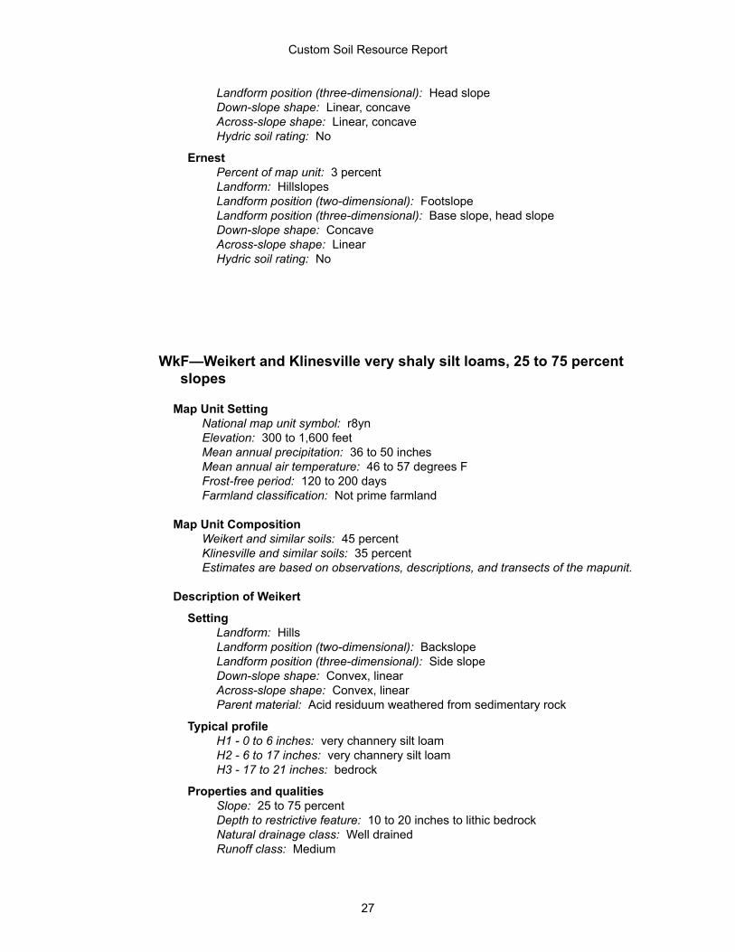
Landform position (three-dimensional): Head slopeDown-slope shape: Linear, concaveAcross-slope shape: Linear, concaveHydric soil rating: No
ErnestPercent of map unit: 3 percentLandform: HillslopesLandform position (two-dimensional): FootslopeLandform position (three-dimensional): Base slope, head slopeDown-slope shape: ConcaveAcross-slope shape: LinearHydric soil rating: No
WkF—Weikert and Klinesville very shaly silt loams, 25 to 75 percentslopes
Map Unit SettingNational map unit symbol: r8ynElevation: 300 to 1,600 feetMean annual precipitation: 36 to 50 inchesMean annual air temperature: 46 to 57 degrees FFrost-free period: 120 to 200 daysFarmland classification: Not prime farmland
Map Unit CompositionWeikert and similar soils: 45 percentKlinesville and similar soils: 35 percentEstimates are based on observations, descriptions, and transects of the mapunit.
Description of Weikert
SettingLandform: HillsLandform position (two-dimensional): BackslopeLandform position (three-dimensional): Side slopeDown-slope shape: Convex, linearAcross-slope shape: Convex, linearParent material: Acid residuum weathered from sedimentary rock
Typical profileH1 - 0 to 6 inches: very channery silt loamH2 - 6 to 17 inches: very channery silt loamH3 - 17 to 21 inches: bedrock
Properties and qualitiesSlope: 25 to 75 percentDepth to restrictive feature: 10 to 20 inches to lithic bedrockNatural drainage class: Well drainedRunoff class: Medium
Custom Soil Resource Report
27
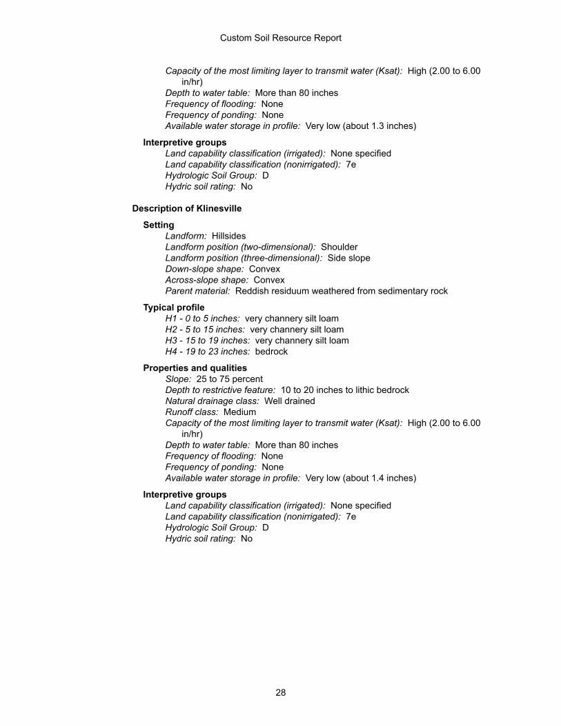
Capacity of the most limiting layer to transmit water (Ksat): High (2.00 to 6.00in/hr)
Depth to water table: More than 80 inchesFrequency of flooding: NoneFrequency of ponding: NoneAvailable water storage in profile: Very low (about 1.3 inches)
Interpretive groupsLand capability classification (irrigated): None specifiedLand capability classification (nonirrigated): 7eHydrologic Soil Group: DHydric soil rating: No
Description of Klinesville
SettingLandform: HillsidesLandform position (two-dimensional): ShoulderLandform position (three-dimensional): Side slopeDown-slope shape: ConvexAcross-slope shape: ConvexParent material: Reddish residuum weathered from sedimentary rock
Typical profileH1 - 0 to 5 inches: very channery silt loamH2 - 5 to 15 inches: very channery silt loamH3 - 15 to 19 inches: very channery silt loamH4 - 19 to 23 inches: bedrock
Properties and qualitiesSlope: 25 to 75 percentDepth to restrictive feature: 10 to 20 inches to lithic bedrockNatural drainage class: Well drainedRunoff class: MediumCapacity of the most limiting layer to transmit water (Ksat): High (2.00 to 6.00
in/hr)Depth to water table: More than 80 inchesFrequency of flooding: NoneFrequency of ponding: NoneAvailable water storage in profile: Very low (about 1.4 inches)
Interpretive groupsLand capability classification (irrigated): None specifiedLand capability classification (nonirrigated): 7eHydrologic Soil Group: DHydric soil rating: No
Custom Soil Resource Report
28
ReferencesAmerican Association of State Highway and Transportation Officials (AASHTO).2004. Standard specifications for transportation materials and methods of samplingand testing. 24th edition.
American Society for Testing and Materials (ASTM). 2005. Standard classification ofsoils for engineering purposes. ASTM Standard D2487-00.
Cowardin, L.M., V. Carter, F.C. Golet, and E.T. LaRoe. 1979. Classification ofwetlands and deep-water habitats of the United States. U.S. Fish and WildlifeService FWS/OBS-79/31.
Federal Register. July 13, 1994. Changes in hydric soils of the United States.
Federal Register. September 18, 2002. Hydric soils of the United States.
Hurt, G.W., and L.M. Vasilas, editors. Version 6.0, 2006. Field indicators of hydricsoils in the United States.
National Research Council. 1995. Wetlands: Characteristics and boundaries.
Soil Survey Division Staff. 1993. Soil survey manual. Soil Conservation Service.U.S. Department of Agriculture Handbook 18. http://www.nrcs.usda.gov/wps/portal/nrcs/detail/national/soils/?cid=nrcs142p2_054262
Soil Survey Staff. 1999. Soil taxonomy: A basic system of soil classification formaking and interpreting soil surveys. 2nd edition. Natural Resources ConservationService, U.S. Department of Agriculture Handbook 436. http://www.nrcs.usda.gov/wps/portal/nrcs/detail/national/soils/?cid=nrcs142p2_053577
Soil Survey Staff. 2010. Keys to soil taxonomy. 11th edition. U.S. Department ofAgriculture, Natural Resources Conservation Service. http://www.nrcs.usda.gov/wps/portal/nrcs/detail/national/soils/?cid=nrcs142p2_053580
Tiner, R.W., Jr. 1985. Wetlands of Delaware. U.S. Fish and Wildlife Service andDelaware Department of Natural Resources and Environmental Control, WetlandsSection.
United States Army Corps of Engineers, Environmental Laboratory. 1987. Corps ofEngineers wetlands delineation manual. Waterways Experiment Station TechnicalReport Y-87-1.
United States Department of Agriculture, Natural Resources Conservation Service.National forestry manual. http://www.nrcs.usda.gov/wps/portal/nrcs/detail/soils/home/?cid=nrcs142p2_053374
United States Department of Agriculture, Natural Resources Conservation Service.National range and pasture handbook. http://www.nrcs.usda.gov/wps/portal/nrcs/detail/national/landuse/rangepasture/?cid=stelprdb1043084
29
United States Department of Agriculture, Natural Resources Conservation Service.National soil survey handbook, title 430-VI. http://www.nrcs.usda.gov/wps/portal/nrcs/detail/soils/scientists/?cid=nrcs142p2_054242
United States Department of Agriculture, Natural Resources Conservation Service.2006. Land resource regions and major land resource areas of the United States,the Caribbean, and the Pacific Basin. U.S. Department of Agriculture Handbook296. http://www.nrcs.usda.gov/wps/portal/nrcs/detail/national/soils/?cid=nrcs142p2_053624
United States Department of Agriculture, Soil Conservation Service. 1961. Landcapability classification. U.S. Department of Agriculture Handbook 210. http://www.nrcs.usda.gov/Internet/FSE_DOCUMENTS/nrcs142p2_052290.pdf
Custom Soil Resource Report
30
ATTACHMENT 2
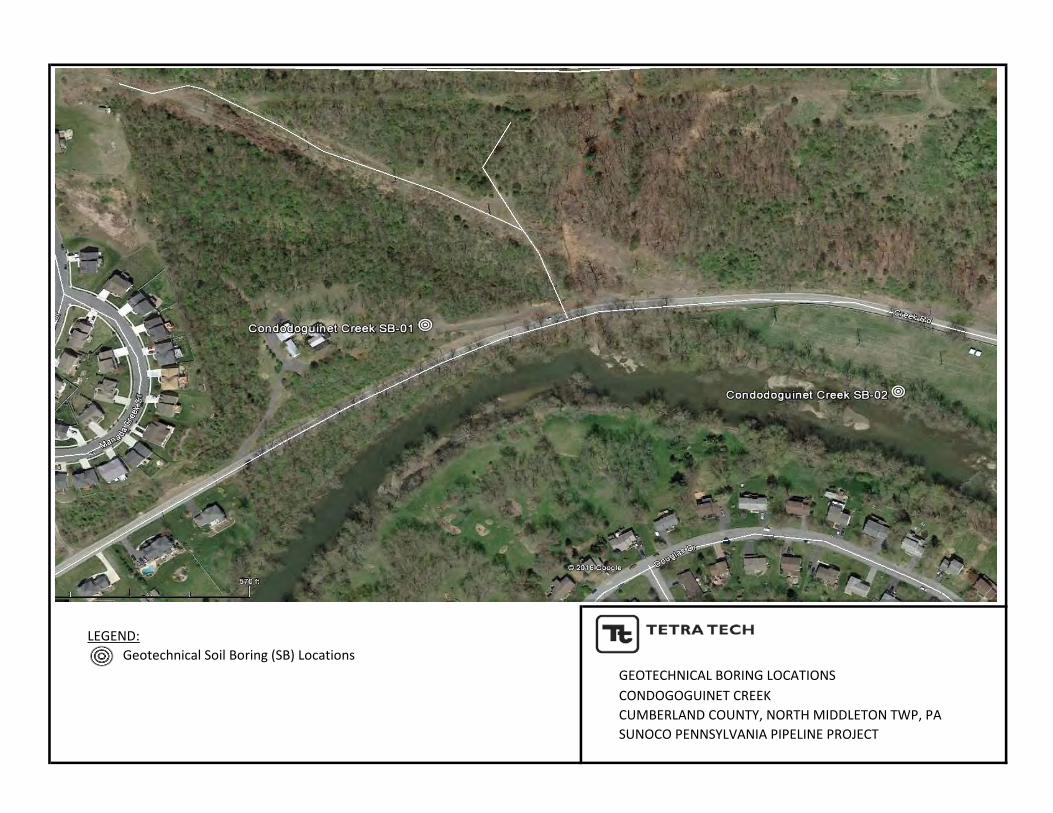
LEGEND:Geotechnical Soil Boring (SB) Locations
GEOTECHNICAL BORING LOCATIONSCONDOGOGUINET CREEKCUMBERLAND COUNTY, NORTH MIDDLETON TWP, PASUNOCO PENNSYLVANIA PIPELINE PROJECT
TB-02
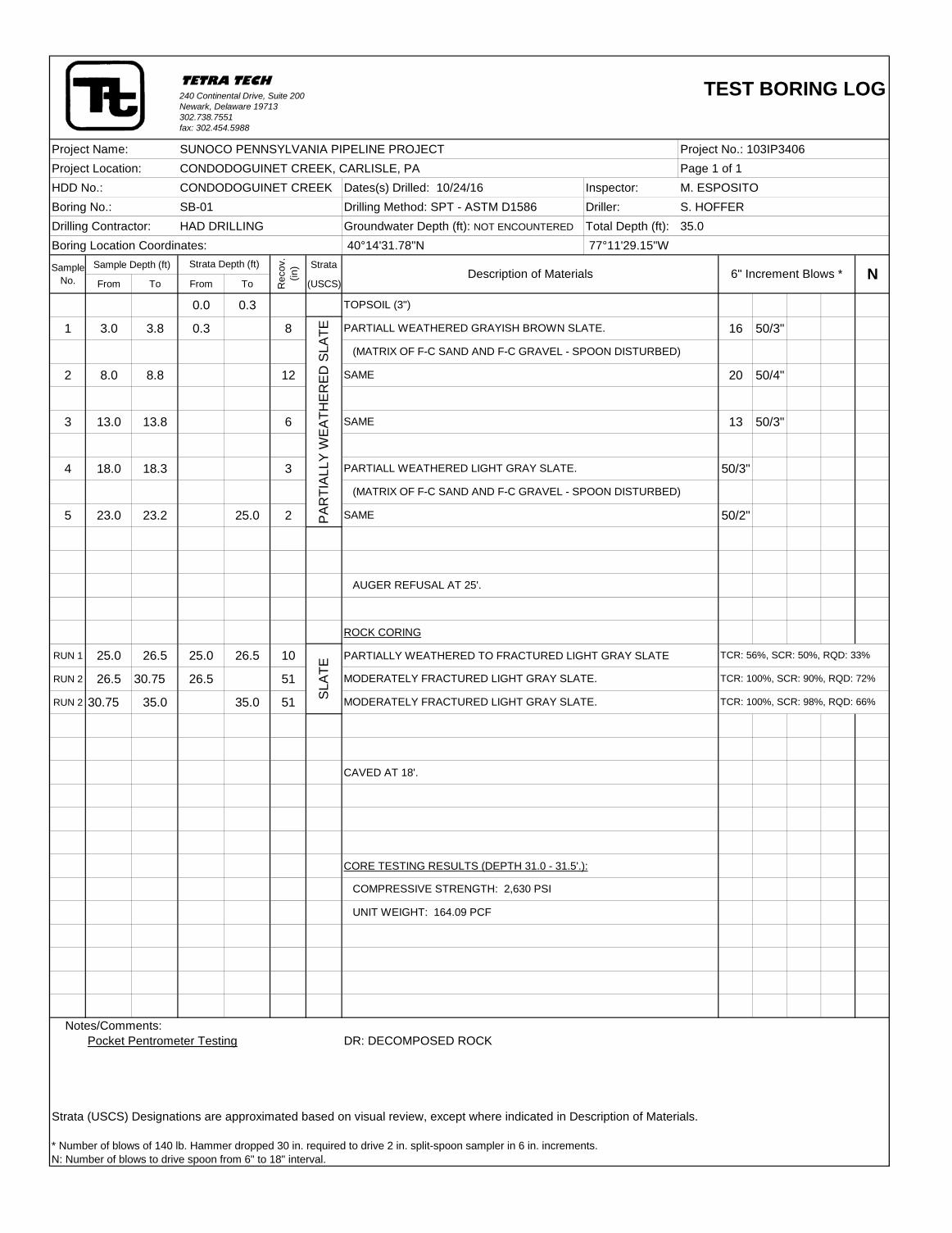
240 Continental Drive, Suite 200 Newark, Delaware 19713302.738.7551fax: 302.454.5988
Project Name: SUNOCO PENNSYLVANIA PIPELINE PROJECT Project No.: 103IP3406
Project Location: CONDODOGUINET CREEK, CARLISLE, PA Page 1 of 1
HDD No.: CONDODOGUINET CREEK Dates(s) Drilled: 10/24/16 Inspector: M. ESPOSITO
Boring No.: SB-01 Drilling Method: SPT - ASTM D1586 Driller: S. HOFFER
Drilling Contractor: HAD DRILLING Groundwater Depth (ft): NOT ENCOUNTERED Total Depth (ft): 35.0
Boring Location Coordinates: 40°14'31.78"N 77°11'29.15"W
Sample Sample Depth (ft) Strata
No. From To From To (USCS)
0.0 0.3
1 3.0 3.8 0.3 8 16 50/3"
2 8.0 8.8 12 20 50/4"
3 13.0 13.8 6 13 50/3"
4 18.0 18.3 3 50/3"
5 23.0 23.2 25.0 2 50/2"
ROCK CORING
RUN 1 25.0 26.5 25.0 26.5 10 PARTIALLY WEATHERED TO FRACTURED LIGHT GRAY SLATE
RUN 2 26.5 30.75 26.5 51
RUN 2 30.75 35.0 35.0 51
CAVED AT 18'.
CORE TESTING RESULTS (DEPTH 31.0 - 31.5'.):
Notes/Comments:
Pocket Pentrometer Testing DR: DECOMPOSED ROCK
Strata (USCS) Designations are approximated based on visual review, except where indicated in Description of Materials.
* Number of blows of 140 lb. Hammer dropped 30 in. required to drive 2 in. split-spoon sampler in 6 in. increments.
N: Number of blows to drive spoon from 6" to 18" interval.
SL
AT
E
SAME
AUGER REFUSAL AT 25'.
PA
RT
IAL
LY
WE
AT
HE
RE
D S
LA
TE
SAME
PARTIALL WEATHERED LIGHT GRAY SLATE.
(MATRIX OF F-C SAND AND F-C GRAVEL - SPOON DISTURBED)
TCR: 56%, SCR: 50%, RQD: 33%
COMPRESSIVE STRENGTH: 2,630 PSI
UNIT WEIGHT: 164.09 PCF
TCR: 100%, SCR: 90%, RQD: 72%
TCR: 100%, SCR: 98%, RQD: 66%
MODERATELY FRACTURED LIGHT GRAY SLATE.
MODERATELY FRACTURED LIGHT GRAY SLATE.
TETRA TECH TEST BORING LOG
Strata Depth (ft)
Re
co
v.
(in
)
Description of Materials 6" Increment Blows * N
TOPSOIL (3")
PARTIALL WEATHERED GRAYISH BROWN SLATE.
(MATRIX OF F-C SAND AND F-C GRAVEL - SPOON DISTURBED)
SAME
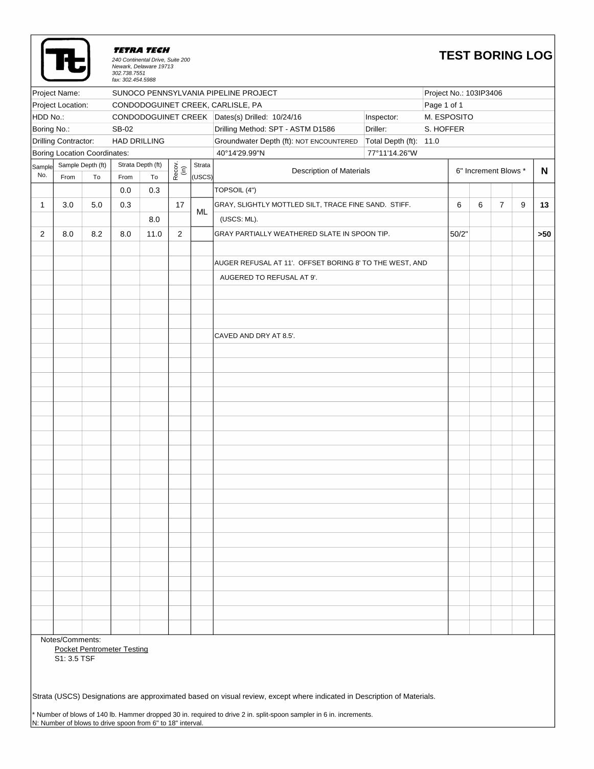
240 Continental Drive, Suite 200 Newark, Delaware 19713302.738.7551fax: 302.454.5988
Project Name: SUNOCO PENNSYLVANIA PIPELINE PROJECT Project No.: 103IP3406
Project Location: CONDODOGUINET CREEK, CARLISLE, PA Page 1 of 1
HDD No.: CONDODOGUINET CREEK Dates(s) Drilled: 10/24/16 Inspector: M. ESPOSITO
Boring No.: SB-02 Drilling Method: SPT - ASTM D1586 Driller: S. HOFFER
Drilling Contractor: HAD DRILLING Groundwater Depth (ft): NOT ENCOUNTERED Total Depth (ft): 11.0
Boring Location Coordinates: 40°14'29.99"N 77°11'14.26"W
Sample Sample Depth (ft) Strata
No. From To From To (USCS)
0.0 0.3
1 3.0 5.0 0.3 17 6 6 7 9 13
8.0
2 8.0 8.2 8.0 11.0 2 50/2" >50
Notes/Comments:
Pocket Pentrometer Testing
S1: 3.5 TSF
Strata (USCS) Designations are approximated based on visual review, except where indicated in Description of Materials.
* Number of blows of 140 lb. Hammer dropped 30 in. required to drive 2 in. split-spoon sampler in 6 in. increments.
N: Number of blows to drive spoon from 6" to 18" interval.
ML
CAVED AND DRY AT 8.5'.
AUGER REFUSAL AT 11'. OFFSET BORING 8' TO THE WEST, AND
AUGERED TO REFUSAL AT 9'.
TOPSOIL (4")
GRAY, SLIGHTLY MOTTLED SILT, TRACE FINE SAND. STIFF.
(USCS: ML).
GRAY PARTIALLY WEATHERED SLATE IN SPOON TIP.
TETRA TECH TEST BORING LOG
Strata Depth (ft)
Re
co
v.
(in
)
Description of Materials 6" Increment Blows * N
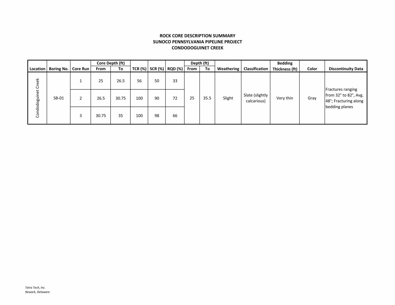
Tetra Tech, Inc.Newark, Delaware
BeddingLocation Boring No. Core Run From To TCR (%) SCR (%) RQD (%) From To Weathering Classification Thickness (ft) Color Discontinuity Data
1 25 26.5 56 50 33
2 26.5 30.75 100 90 72
3 30.75 35 100 98 66Cond
odog
uine
t Cre
ekROCK CORE DESCRIPTION SUMMARY
SUNOCO PENNSYLVANIA PIPELINE PROJECTCONDODOGUINET CREEK
Core Depth (ft) Depth (ft)
SB-01 25 35.5 SlightSlate (slightly
calcarious)Very thin Gray
Fractures ranging from 32° to 82°, Avg. 48°; Fracturing along bedding planes
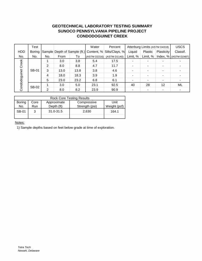
Tetra TechNewark, Delaware
Test Water Percent USCS
HDD Boring Sample Content, % Silts/Clays, % Liquid Plastic Plasticity Classif.
No. No. No. From To (ASTM D2216) (ASTM D1140) Limit, % Limit, % Index, % (ASTM D2487)
1 3.0 3.8 5.4 17.5 - - - -
2 8.0 8.8 4.7 11.7 - - - -
3 13.0 13.8 3.8 4.6 - - - -
4 18.0 18.3 3.9 1.9 - - - -
5 23.0 23.2 6.8 6.1 - - - -
1 3.0 5.0 23.1 92.5 40 28 12 ML
2 8.0 8.2 23.9 90.9 - - - -
Boring Core Unit
No. Run Weight (pcf)
SB-01 3 164.1
Notes:
1) Sample depths based on feet below grade at time of exploration.
31.0-31.5 2,630
Depth (ft)
Condodoguin
et C
reek
SB-01
SB-02
Strength (psi)
Rock Core Testing Results
Approximate Compressive
GEOTECHNICAL LABORATORY TESTING SUMMARY
SUNOCO PENNSYLVANIA PIPELINE PROJECT
CONDODOGUINET CREEK
Atterburg Limits (ASTM D4318)
Depth of Sample (ft.)
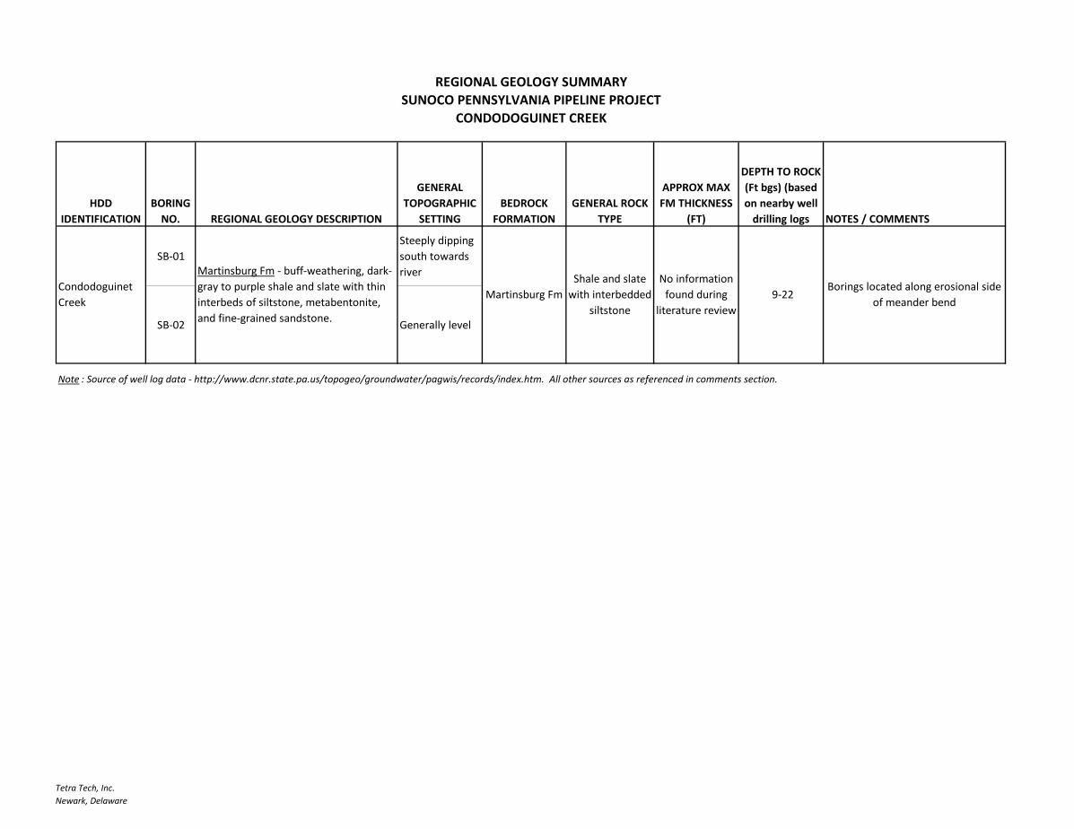
Tetra Tech, Inc.Newark, Delaware
HDD IDENTIFICATION
BORING NO. REGIONAL GEOLOGY DESCRIPTION
GENERAL TOPOGRAPHIC
SETTINGBEDROCK
FORMATIONGENERAL ROCK
TYPE
APPROX MAX FM THICKNESS
(FT)
DEPTH TO ROCK (Ft bgs) (based on nearby well
drilling logs NOTES / COMMENTS
SB-01Steeply dipping south towards river
SB-02 Generally level
Note : Source of well log data - http://www.dcnr.state.pa.us/topogeo/groundwater/pagwis/records/index.htm. All other sources as referenced in comments section.
Borings located along erosional side of meander bend
Condodoguinet Creek
REGIONAL GEOLOGY SUMMARY
CONDODOGUINET CREEKSUNOCO PENNSYLVANIA PIPELINE PROJECT
Martinsburg Fm - buff-weathering, dark-gray to purple shale and slate with thin interbeds of siltstone, metabentonite, and fine-grained sandstone.
Martinsburg FmShale and slate
with interbedded siltstone
No information found during
literature review 9-22
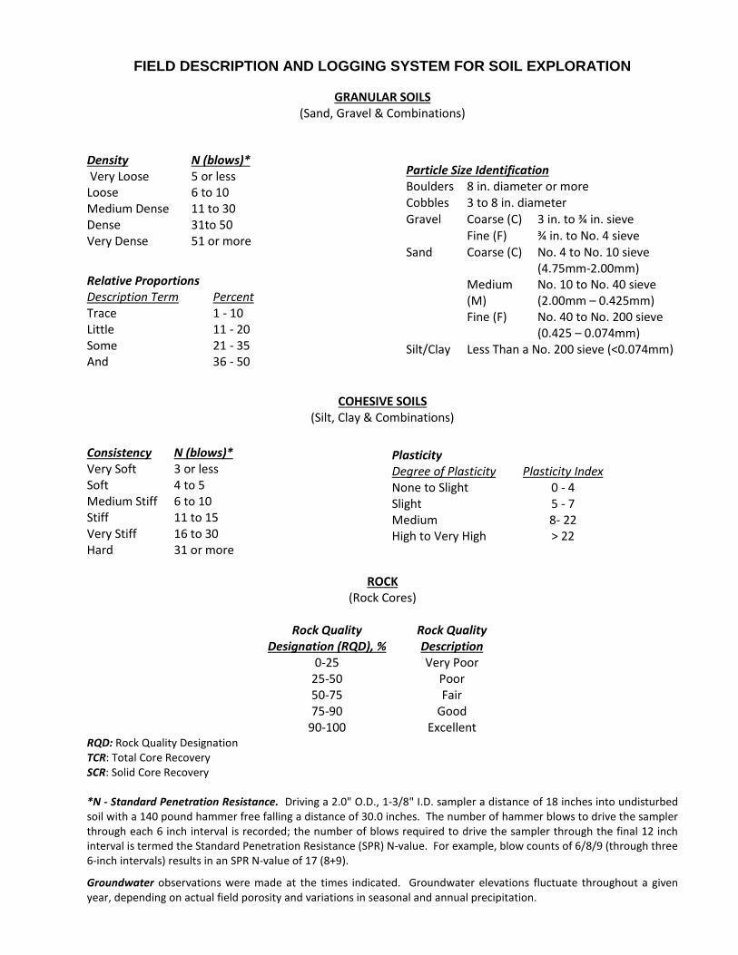
FIELD DESCRIPTION AND LOGGING SYSTEM FOR SOIL EXPLORATION
GRANULAR SOILS (Sand, Gravel & Combinations)
Density N (blows)* Very Loose 5 or less Loose 6 to 10 Medium Dense 11 to 30 Dense 31to 50 Very Dense 51 or more
Relative Proportions Description Term Percent Trace 1 - 10 Little 11 - 20 Some 21 - 35 And 36 - 50
COHESIVE SOILS (Silt, Clay & Combinations)
ROCK (Rock Cores)
Rock Quality
Designation (RQD), % Rock Quality Description
0-25 Very Poor 25-50 Poor 50-75 Fair 75-90 Good
90-100 Excellent RQD: Rock Quality Designation TCR: Total Core Recovery SCR: Solid Core Recovery *N - Standard Penetration Resistance. Driving a 2.0" O.D., 1-3/8" I.D. sampler a distance of 18 inches into undisturbed soil with a 140 pound hammer free falling a distance of 30.0 inches. The number of hammer blows to drive the sampler through each 6 inch interval is recorded; the number of blows required to drive the sampler through the final 12 inch interval is termed the Standard Penetration Resistance (SPR) N-value. For example, blow counts of 6/8/9 (through three 6-inch intervals) results in an SPR N-value of 17 (8+9).
Groundwater observations were made at the times indicated. Groundwater elevations fluctuate throughout a given year, depending on actual field porosity and variations in seasonal and annual precipitation.
Particle Size Identification Boulders 8 in. diameter or more Cobbles 3 to 8 in. diameter Gravel Coarse (C) 3 in. to ¾ in. sieve Fine (F) ¾ in. to No. 4 sieve Sand Coarse (C) No. 4 to No. 10 sieve
(4.75mm-2.00mm) Medium
(M) No. 10 to No. 40 sieve (2.00mm – 0.425mm)
Fine (F) No. 40 to No. 200 sieve (0.425 – 0.074mm)
Silt/Clay Less Than a No. 200 sieve (<0.074mm)
Consistency N (blows)* Very Soft 3 or less Soft 4 to 5 Medium Stiff 6 to 10 Stiff 11 to 15 Very Stiff 16 to 30 Hard 31 or more
Plasticity Degree of Plasticity Plasticity Index None to Slight 0 - 4 Slight 5 - 7 Medium 8- 22 High to Very High > 22
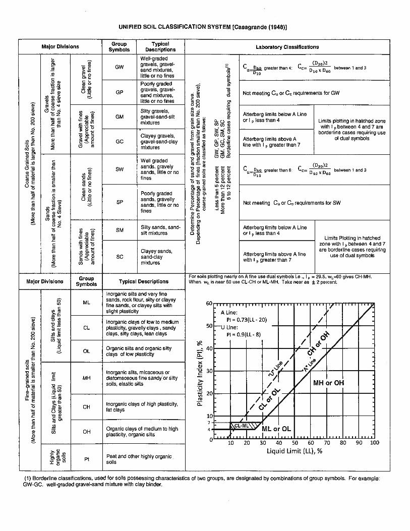
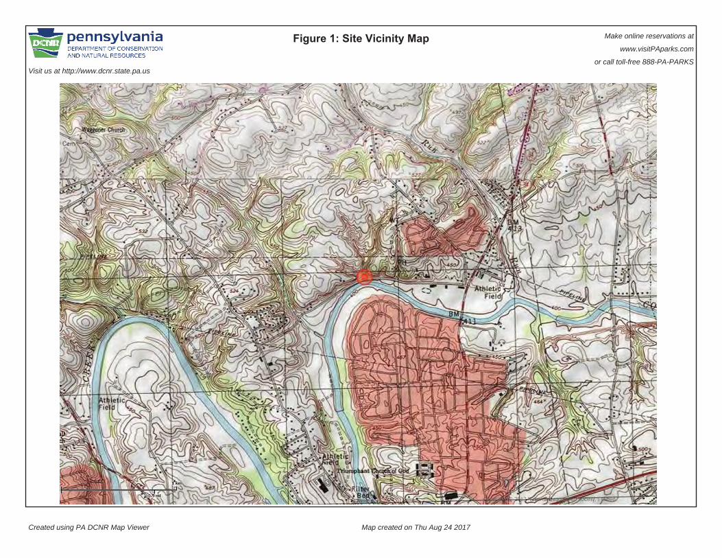
Figure 1: Site Vicinity Map Make online reservations at
www.visitPAparks.com
or call toll-free 888-PA-PARKSVisit us at http://www.dcnr.state.pa.us
Created using PA DCNR Map Viewer Map created on Thu Aug 24 2017
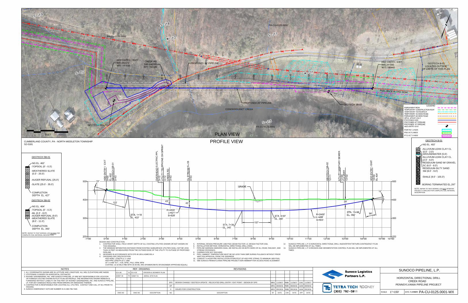
CREEK RD
N40.242185
W77.190328
0+
00
1+
00
2+
00
3+
00
4+
00
5+
00
6+
00
7+
00
8+
00
9+
00
10+
00
11+
00
12+
00
13+
00
14+
00
14+
50
HDD ENTRY / EXIT
N40.242372
W77.191533
GEOTECH SB-01
GEOTECH SB-02
HDD ENTRY / EXIT
N40.241583
W77.186442
200
300
400
500
200
300
400
500
-1+00 0+00 1+00 2+00 3+00 4+00 5+00 6+00 7+00 8+00 9+00 10+00 11+00 12+00 13+00 14+00 15+00 15+50
122'
56'
12°
STA. 1+18
EL. 422'
STA. 13+96
EL. 392'
GRADE
157'
STA. 8+97
EL. 340'
STA. 7+39
EL. 340'
43'
CR
EE
K R
D
3+
43
OV
ER
HE
AD
E
LE
CT
RIC
P
PL
3+
10
UT
ILIT
Y T
ELE
PH
ON
E O
H S
PR
IN
T
3+
12
HD
D E
NT
RY
/ E
XIT
0+
00
EL.453'
HD
D E
NT
RY
/ E
XIT
14+
50
EL.404'
43'
15°
GE
OT
EC
H S
B-02
12+
11
GE
OT
EC
H S
B-01
0+
43
CL S
TR
EA
M S
-J18
4+
53
CU
LV
ER
T
13+
02
UT
ILIT
Y S
AN
IT
AR
Y S
EW
ER
12+
90
29'
R=2400'
L=621'
S=628'
R=2400'
L=499'
S=503'
PA-CU-0125.0000
CONODOGUINET CREEK
0
FEET
75 75 150
PROPOSED 20" PIPELINE
LEGEND
PERMANENT ROW
TEMPORARY CONSTRUCTION ROW
TEMPORARY WORKSPACE
TEMPORARY ACCESS ROAD
PERMANENT ACCESS ROAD
SPOIL SPACE ONLY
PROPOSED HDD
PROPOSED 20" PIPELINE
PROPOSED 16" PIPELINE
HDD ENTRY-EXIT
PEM WETLANDS
PSS WETLANDS
PFO WETLANDS
PLAN VIEW
PROFILE VIEW
Sunoco LogisticsPartners L.P.
HORIZONTAL DIRECTIONAL DRILL
SUNOCO PIPELINE, L.P.
PENNSYLVANIA PIPELINE PROJECT
DESIGN AND CONSTRUCTION:
1. CONTRACTOR SHALL FIELD VERIFY DEPTH OF ALL EXISTING UTILITIES SHOWN OR NOT SHOWN ON
THIS DRAWING.
2. THE MINIMUM SEPARATION DISTANCE FROM EXISTING SUBSURFACE UTILITIES SHALL NOT BE LESS
THAN 10 FEET AS MEASURED FROM THE OUTSIDE EDGE OF THE UTILITY TO OUTSIDE OF PROPOSED
PIPELINE.
3. DESIGNED IN ACCORDANCE WITH CFR 49 195 & ASME B31.4
4. CROSSING PIPE SPECIFICATION:
HDD HORZ. LENGTH (L=):
HDD PIPE LENGTH (S=):
20" x 0.456" W.T., X-65, API5L, PSL2, ERW, BFW
COATING: 14-16 MILS FBE WITH 30-35 MIL ARO (POWERCRETE OR ENGINEER APPROVED EQUAL)
5. INTERNAL DESIGN PRESSURE 1480 PSIG (SEAM FACTOR 1.0, DESIGH FACTOR 0.50).
6. INSTALLATION METHOD: HORIZONTAL DIRECTIONAL DRILL (HDD).
7. PIPELINE WARNING MARKERS SHALL BE INSTALLED ON BOTH SIDES OF ALL ROAD, RAILWAY, AND
STREAM CROSSINGS.
8. CARRIER PIPE NOT ENCASED.
9. PIPE / AMBIENT TEMPERATURE MUST BE NO LESS THAN 30°F DURING PULLBACK WITHOUT PRIOR
WRITTEN APPROVAL FROM THE ENGINEER.
10. CONDUCT 4-HOUR PRE-INSTALLATION HYDROTEST OF HDD PIPE STRING TO MINIMUM 1850 PSIG.
11. SEE SUNOCO PENNSYLVANIA PIPELINE PROJECT ESRI WEBMAP FOR ACCESS ROAD ALIGNMENT.
12. SUNOCO PIPELINE, L.P.'S HORIZONTAL DIRECTIONAL DRILL INADVERTENT RETURN CONTINGENCY PLAN
WILL BE IMPLEMENTED AT ALL TIMES.
13. SUNOCO PIPELINE, L.P.'S EROSION AND SEDIMENTATION CONTROL PLAN WILL BE IMPLEMENTED AT ALL
TIMES.
PA-CU-0126.0000
PU
LL B
AC
K A
LO
NG
RO
W
NOTE: REFER TO TEST BORING LOG S2-0181 FOR
COMPLETE SOIL MATERIAL DESCRIPTION
GEOTECH SB-01
-NG EL. 462'
-TOPSOIL (0' - 0.3')
-COMPLETION
DEPTH EL. 427'
-WEATHERED SLATE
(0.3' - 25.0')
-AUGER REFUSAL (25.0')
-SLATE (25.0' - 35.0')
GEOTECH SB-02
-NG EL. 404'
-TOPSOIL (0' - 0.3')
-COMPLETION
DEPTH EL. 393'
-ML (0.3' - 8.0')
-WEATHERED SLATE
(8.0' - 11.0')
-AUGER REFUSAL (9.0')
PA-CU-0125.0001
PROPOSED 16" PIPELINE
GEOTECH B-01
-NG EL. 402'
-BORING TERMINATED EL.297'
-SHALE (9.0' - 105.0')
NOTE: REFER TO TEST BORING LOG B-01 INTERTEK
PROJECT # 04911453 FOR COMPLETE SOIL MATERIAL
DESCRIPTION
-ALLUVIUM-LEAN CLAY CL
(0.0' - 2.0')
-RESIDUUM-SAND W/ GRAVEL
SC (6.0' - 8.0')
-ALLUVIUM-LEAN CLAY CL
(2.0' - 6.0')
-RESIDUUM-SILTY SAND
SM (8.0' - 9.0')
-GROUNDWATER (5.6')
GEOTECH B-01
LOCATED OUTSIDE
OF LIMITS OF THIS PLAN
CREEK ROAD
1"=150'
PA-CU-0125.0001-WX
CUMBERLAND COUNTY, PA - NORTH MIDDLETON TOWNSHIP
S2-0181
1450'
1466'
REF. DRAWING
EROSION & SEDIMENT PLAN
AERIAL SITE PLAN
NO. DESCRIPTION DATEBY CHK DATE
REVISIONS
DATEAPP
NOTES
1. ALL COORDINATES SHOWN ARE IN LATITUDE AND LONGITUDE. ALL MSL ELEVATIONS ARE NAD83
2. STATIONING IS BASED ON HORIZONTAL DISTANCES.
3. ROONEY ENGINEERING, INC. AND SUNOCO PIPELINE, LP ARE NOT RESPONSIBLE FOR LOCATION
OF FOREIGN UTILITIES SHOWN IN PLOT PLAN OR PROFILE. THE INFORMATION SHOWN HEREON IS
FURNISHED WITHOUT LIABILITY ON THE PART OF ROONEY ENGINEERING, INC. AND SUNOCO PIPELINE,
LP, FOR ANY DAMAGES RESULTING FROM ERRORS OR OMISSIONS THEREIN.
4. CONTRACTOR IS RESPONSIBLE FOR LOCATING ALL UTILITIES. CONTACT ONE CALL AT 811 PRIOR TO
DIGGING.
5. SUNOCO EMERGENCY HOTLINE NUMBER IS #1-800-786-7440.
TO
TO
DWG NO DWG NO DESCRIPTION
09/19/160 ISSUED FOR CONSTRUCTION
MRS RMB AAW09/19/1609/19/16
09/30/16
ES-4.48
SHEET 31
EP2MRS RMB CAG
ES-4.50
11/29/17
EP MRS RMB AAW09/30/16
SHEET 30
09/30/16
DESIGN CHANGE / GEOTECH UPDATE - RELOCATED DRILL ENTRY / EXIT POINT - DESIGN BY DPS11/29/17 11/29/17
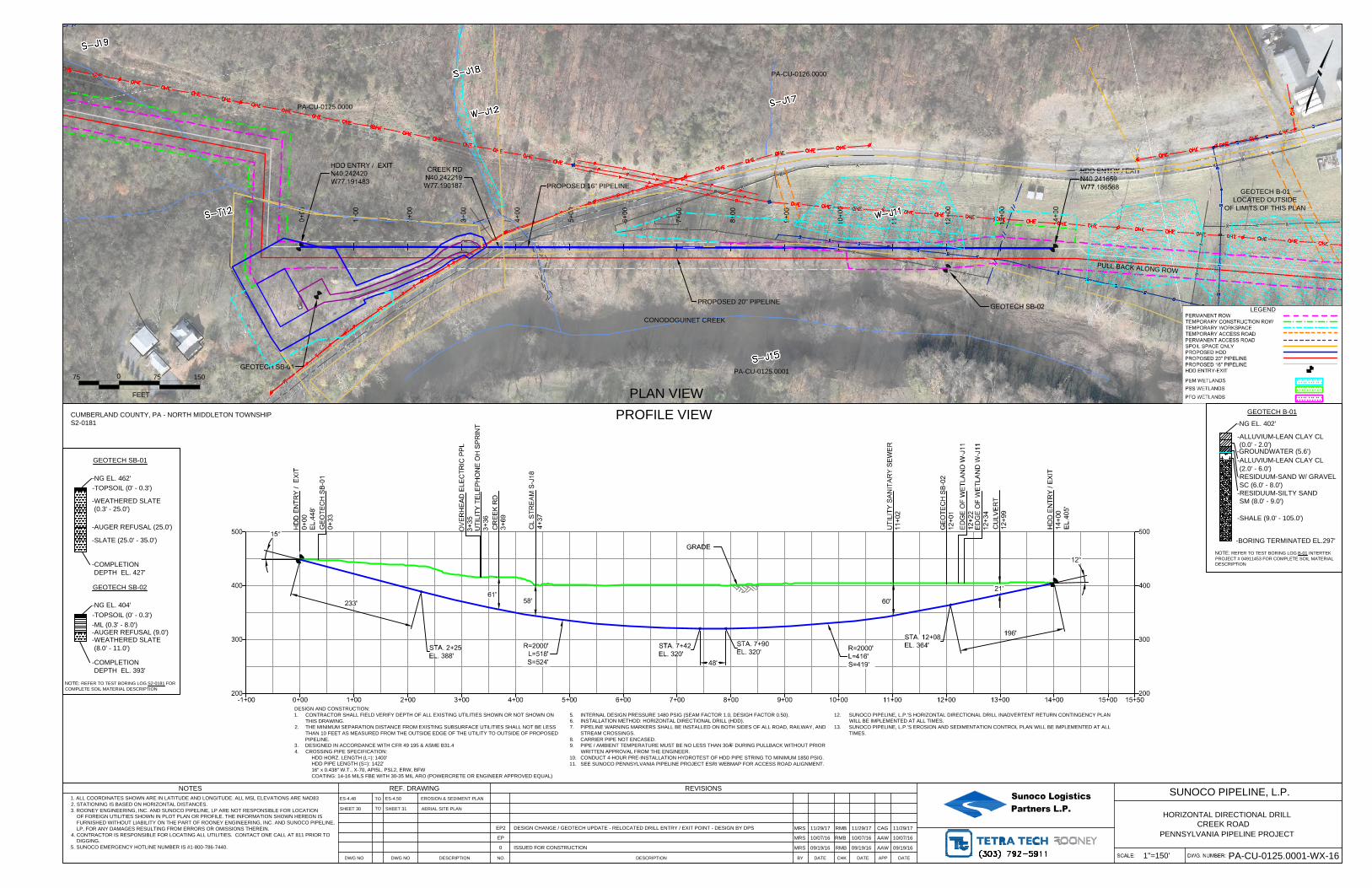
CREEK RD
N40.242219
W77.190187
0+
00
1+
00
2+
00
3+
00
4+
00
5+
00
6+
00
7+
00
8+
00
9+
00
10+
00
11+
00
12+
00
13+
00
14+
00
HDD ENTRY / EXIT
N40.242420
W77.191483
GEOTECH SB-01
GEOTECH SB-02
HDD ENTRY / EXIT
N40.241659
W77.186568
200
300
400
500
200
300
400
500
-1+00 0+00 1+00 2+00 3+00 4+00 5+00 6+00 7+00 8+00 9+00 10+00 11+00 12+00 13+00 14+00 15+00 15+50
233'
196'
12°
STA. 2+25
EL. 388'
STA. 12+08
EL. 364'
GRADE
48'
STA. 7+90
EL. 320'
STA. 7+42
EL. 320'
58'
CR
EE
K R
D
3+
69
OV
ER
HE
AD
E
LE
CT
RIC
P
PL
3+
35
UT
ILIT
Y T
ELE
PH
ON
E O
H S
PR
IN
T
3+
36
HD
D E
NT
RY
/ E
XIT
0+
00
EL.448'
HD
D E
NT
RY
/ E
XIT
14+
00
EL.405'
61'
15°
GE
OT
EC
H S
B-02
12+
01
GE
OT
EC
H S
B-01
0+
33
CL S
TR
EA
M S
-J18
4+
37
CU
LV
ER
T
12+
99
UT
ILIT
Y S
AN
IT
AR
Y S
EW
ER
11+
02
21'
60'
R=2000'
L=518'
S=524'
R=2000'
L=416'
S=419'
ED
GE
O
F W
ET
LA
ND
W
-J11
12+
34
ED
GE
O
F W
ET
LA
ND
W
-J11
12+
22
PA-CU-0125.0000
CONODOGUINET CREEK
0
FEET
75 75 150
PROPOSED 20" PIPELINE
LEGEND
PERMANENT ROW
TEMPORARY CONSTRUCTION ROW
TEMPORARY WORKSPACE
TEMPORARY ACCESS ROAD
PERMANENT ACCESS ROAD
SPOIL SPACE ONLY
PROPOSED HDD
PROPOSED 20" PIPELINE
PROPOSED 16" PIPELINE
HDD ENTRY-EXIT
PEM WETLANDS
PSS WETLANDS
PFO WETLANDS
PLAN VIEW
PROFILE VIEW
Sunoco LogisticsPartners L.P.
HORIZONTAL DIRECTIONAL DRILL
SUNOCO PIPELINE, L.P.
PENNSYLVANIA PIPELINE PROJECT
DESIGN AND CONSTRUCTION:
1. CONTRACTOR SHALL FIELD VERIFY DEPTH OF ALL EXISTING UTILITIES SHOWN OR NOT SHOWN ON
THIS DRAWING.
2. THE MINIMUM SEPARATION DISTANCE FROM EXISTING SUBSURFACE UTILITIES SHALL NOT BE LESS
THAN 10 FEET AS MEASURED FROM THE OUTSIDE EDGE OF THE UTILITY TO OUTSIDE OF PROPOSED
PIPELINE.
3. DESIGNED IN ACCORDANCE WITH CFR 49 195 & ASME B31.4
4. CROSSING PIPE SPECIFICATION:
HDD HORZ. LENGTH (L=):
HDD PIPE LENGTH (S=):
16" x 0.438" W.T., X-70, API5L, PSL2, ERW, BFW
COATING: 14-16 MILS FBE WITH 30-35 MIL ARO (POWERCRETE OR ENGINEER APPROVED EQUAL)
5. INTERNAL DESIGN PRESSURE 1480 PSIG (SEAM FACTOR 1.0, DESIGH FACTOR 0.50).
6. INSTALLATION METHOD: HORIZONTAL DIRECTIONAL DRILL (HDD).
7. PIPELINE WARNING MARKERS SHALL BE INSTALLED ON BOTH SIDES OF ALL ROAD, RAILWAY, AND
STREAM CROSSINGS.
8. CARRIER PIPE NOT ENCASED.
9. PIPE / AMBIENT TEMPERATURE MUST BE NO LESS THAN 30°F DURING PULLBACK WITHOUT PRIOR
WRITTEN APPROVAL FROM THE ENGINEER.
10. CONDUCT 4-HOUR PRE-INSTALLATION HYDROTEST OF HDD PIPE STRING TO MINIMUM 1850 PSIG.
11. SEE SUNOCO PENNSYLVANIA PIPELINE PROJECT ESRI WEBMAP FOR ACCESS ROAD ALIGNMENT.
12. SUNOCO PIPELINE, L.P.'S HORIZONTAL DIRECTIONAL DRILL INADVERTENT RETURN CONTINGENCY PLAN
WILL BE IMPLEMENTED AT ALL TIMES.
13. SUNOCO PIPELINE, L.P.'S EROSION AND SEDIMENTATION CONTROL PLAN WILL BE IMPLEMENTED AT ALL
TIMES.
PA-CU-0126.0000
PU
LL B
AC
K A
LO
NG
RO
W
NOTE: REFER TO TEST BORING LOG S2-0181 FOR
COMPLETE SOIL MATERIAL DESCRIPTION
GEOTECH SB-01
-NG EL. 462'
-TOPSOIL (0' - 0.3')
-COMPLETION
DEPTH EL. 427'
-WEATHERED SLATE
(0.3' - 25.0')
-AUGER REFUSAL (25.0')
-SLATE (25.0' - 35.0')
GEOTECH SB-02
-NG EL. 404'
-TOPSOIL (0' - 0.3')
-COMPLETION
DEPTH EL. 393'
-ML (0.3' - 8.0')
-WEATHERED SLATE
(8.0' - 11.0')
-AUGER REFUSAL (9.0')
PA-CU-0125.0001
PROPOSED 16" PIPELINE
GEOTECH B-01
-NG EL. 402'
-BORING TERMINATED EL.297'
-SHALE (9.0' - 105.0')
NOTE: REFER TO TEST BORING LOG B-01 INTERTEK
PROJECT # 04911453 FOR COMPLETE SOIL MATERIAL
DESCRIPTION
-ALLUVIUM-LEAN CLAY CL
(0.0' - 2.0')
-RESIDUUM-SAND W/ GRAVEL
SC (6.0' - 8.0')
-ALLUVIUM-LEAN CLAY CL
(2.0' - 6.0')
-RESIDUUM-SILTY SAND
SM (8.0' - 9.0')
-GROUNDWATER (5.6')
GEOTECH B-01
LOCATED OUTSIDE
OF LIMITS OF THIS PLAN
CREEK ROAD
1"=150'
PA-CU-0125.0001-WX-16
CUMBERLAND COUNTY, PA - NORTH MIDDLETON TOWNSHIP
S2-0181
1400'
1422'
REF. DRAWING
EROSION & SEDIMENT PLAN
AERIAL SITE PLAN
NO. DESCRIPTION DATEBY CHK DATE
REVISIONS
DATEAPP
NOTES
1. ALL COORDINATES SHOWN ARE IN LATITUDE AND LONGITUDE. ALL MSL ELEVATIONS ARE NAD83
2. STATIONING IS BASED ON HORIZONTAL DISTANCES.
3. ROONEY ENGINEERING, INC. AND SUNOCO PIPELINE, LP ARE NOT RESPONSIBLE FOR LOCATION
OF FOREIGN UTILITIES SHOWN IN PLOT PLAN OR PROFILE. THE INFORMATION SHOWN HEREON IS
FURNISHED WITHOUT LIABILITY ON THE PART OF ROONEY ENGINEERING, INC. AND SUNOCO PIPELINE,
LP, FOR ANY DAMAGES RESULTING FROM ERRORS OR OMISSIONS THEREIN.
4. CONTRACTOR IS RESPONSIBLE FOR LOCATING ALL UTILITIES. CONTACT ONE CALL AT 811 PRIOR TO
DIGGING.
5. SUNOCO EMERGENCY HOTLINE NUMBER IS #1-800-786-7440.
TO
TO
DWG NO DWG NO DESCRIPTION
09/19/160 ISSUED FOR CONSTRUCTION
MRS RMB AAW09/19/1609/19/16
10/07/16
ES-4.48
SHEET 31
EP2
ES-4.50
EP MRS RMB AAW10/07/16
SHEET 30
10/07/16
DESIGN CHANGE / GEOTECH UPDATE - RELOCATED DRILL ENTRY / EXIT POINT - DESIGN BY DPSMRS RMB CAG11/29/17 11/29/17 11/29/17
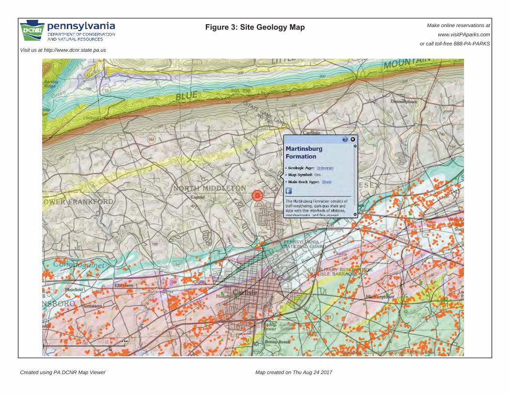
Figure 3: Site Geology Map Make online reservations at
www.visitPAparks.com
or call toll-free 888-PA-PARKSVisit us at http://www.dcnr.state.pa.us
Created using PA DCNR Map Viewer Map created on Thu Aug 24 2017
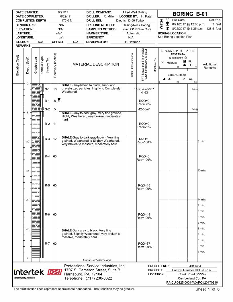
S-1
R-1
S-2
R-2
R-3
R-4
R-5
R-6
R-7
16
8
5
11
12
60
60
60
60
RQD=0Rec=30%
RQD=0Rec=22%
RQD=0Rec=100%
RQD=0Rec=100%
RQD=15Rec=100%
RQD=44Rec=100%
RQD=87Rec=100%
11-21-42-50/5"N=63
42-50/4"
SHALE-Gray-brown to black, sand- andgravel-sized particles, Highly to CompletelyWeathered
SHALE-Gray to dark gray, Very fine grained,Highly Weathered, very broken, moderatelyhard
SHALE-Gray to dark gray-brown, Very finegrained, Weathered to Slightly Weathered,very broken to massive, moderately hard
SHALE-Dark gray to black, Very finegrained, Slightly Weathered, very broken tomassive, moderately hard
5 min.
13 min.
14 min.
4 min.
3 min.
3 min.
3 min.
3 min.
4 min.
3 min.
3 min.
3 min.
PROJECT NO.: 04911454PROJECT: Energy Transfer HDD (DPS)
Dep
th, (
feet
)
STRENGTH, tsf
AdditionalRemarks
US
CS
Cla
ssifi
catio
n
0
Qp
Sam
ple
Typ
e
2.0
0
Moi
stur
e, %
MoistureMATERIAL DESCRIPTION
STANDARD PENETRATIONTEST DATA
N in blows/ft
Qu
Sam
ple
No.
Gra
phic
Log
50
PL
Ele
vatio
n (f
eet)
LL
4.0
25
Rec
over
y (in
ches
)
138.5 feet
Pre-Core
8/21/2017 @ 12:00 p.m.
8/22/2017 @ 1:35 p.m.
Continued Next Page
LATITUDE: n/a°LONGITUDE: n/a°
LOCATION: Creek Road (PPP4)
3 feet
Not Enc.
Wat
er
REMARKS:
DRILLER: R. Miller
Professional Service Industries, Inc.1707 S. Cameron Street, Suite BHarrisburg, PA 17104Telephone: (717) 230-8622 Cumberland Co., PA
PA-CU-0125.0001-WX/PO#20170816
SP
T B
low
s pe
r 6-
inch
(S
S)
RQ
D &
Rec
over
y %
(N
X)
SAMPLING METHOD: 2-in SS1.874-in Core
DATE STARTED: 8/21/17
BENCHMARK: N/A
The stratification lines represent approximate boundaries. The transition may be gradual. Sheet 1 of 6
DRILL COMPANY: Allied Well Drilling
STATION: N/A OFFSET: N/A
LOGGED BY: H. PatelCOMPLETION DEPTH 175.0 ft DRILL RIG: Diedrich D-50 Turbo
DRILLING METHOD: Casing/Rock CoringELEVATION: N/A
REVIEWED BY: F. Hoffman
EFFICIENCY N/A See Boring Location PlanHAMMER TYPE: Automatic BORING LOCATION:
0
5
10
15
20
25
30
DATE COMPLETED: 8/22/17 BORING B-01
>>
>>
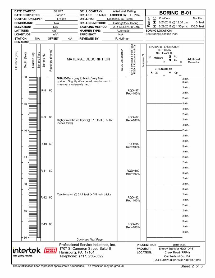
R-8
R-9
R-10
R-11
R-12
R-13
60
60
60
60
60
60
RQD=97Rec=100%
RQD=67Rec=100%
RQD=95Rec=100%
RQD=100Rec=100%
RQD=92Rec=100%
RQD=83Rec=100%
SHALE-Dark gray to black, Very finegrained, Slightly Weathered, very broken tomassive, moderately hard
Highly Weathered layer @ 37.8 feet (~ 3-1/2inches thick)
Calcite seam @ 51.7 feet (~ 3/4 inch thick)
2 min.3 min.
3 min.
2 min.
2 min.
3 min.
3 min.
2 min.
2 min.
3 min.
2 min.
2 min.
3 min.
3 min.
3 min.
2 min.
2 min.
2 min.
3 min.
2 min.
2 min.
3 min.
2 min.
3 min.
2 min.
2 min.
2 min.
3 min.
3 min.
3 min.
PROJECT NO.: 04911454PROJECT: Energy Transfer HDD (DPS)
Dep
th, (
feet
)
STRENGTH, tsf
AdditionalRemarks
US
CS
Cla
ssifi
catio
n
0
Qp
Sam
ple
Typ
e
2.0
0
Moi
stur
e, %
MoistureMATERIAL DESCRIPTION
STANDARD PENETRATIONTEST DATA
N in blows/ft
Qu
Sam
ple
No.
Gra
phic
Log
50
PL
Ele
vatio
n (f
eet)
LL
4.0
25
Rec
over
y (in
ches
)
138.5 feet
Pre-Core
8/21/2017 @ 12:00 p.m.
8/22/2017 @ 1:35 p.m.
Continued Next Page
LATITUDE: n/a°LONGITUDE: n/a°
LOCATION: Creek Road (PPP4)
3 feet
Not Enc.
Wat
er
REMARKS:
DRILLER: R. Miller
Professional Service Industries, Inc.1707 S. Cameron Street, Suite BHarrisburg, PA 17104Telephone: (717) 230-8622 Cumberland Co., PA
PA-CU-0125.0001-WX/PO#20170816
SP
T B
low
s pe
r 6-
inch
(S
S)
RQ
D &
Rec
over
y %
(N
X)
SAMPLING METHOD: 2-in SS1.874-in Core
DATE STARTED: 8/21/17
BENCHMARK: N/A
The stratification lines represent approximate boundaries. The transition may be gradual. Sheet 2 of 6
DRILL COMPANY: Allied Well Drilling
STATION: N/A OFFSET: N/A
LOGGED BY: H. PatelCOMPLETION DEPTH 175.0 ft DRILL RIG: Diedrich D-50 Turbo
DRILLING METHOD: Casing/Rock CoringELEVATION: N/A
REVIEWED BY: F. Hoffman
EFFICIENCY N/A See Boring Location PlanHAMMER TYPE: Automatic BORING LOCATION:
30
35
40
45
50
55
60
DATE COMPLETED: 8/22/17 BORING B-01
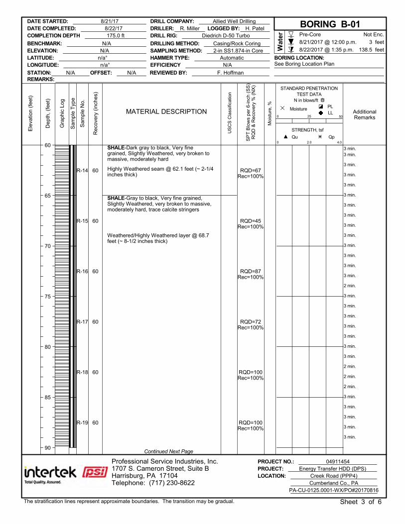
R-14
R-15
R-16
R-17
R-18
R-19
60
60
60
60
60
60
RQD=67Rec=100%
RQD=45Rec=100%
RQD=87Rec=100%
RQD=72Rec=100%
RQD=100Rec=100%
RQD=100Rec=100%
SHALE-Dark gray to black, Very finegrained, Slightly Weathered, very broken tomassive, moderately hard
Highly Weathered seam @ 62.1 feet (~ 2-1/4inches thick)
SHALE-Gray to black, Very fine grained,Slightly Weathered, very broken to massive,moderately hard, trace calcite stringers
Weathered/Highly Weathered layer @ 68.7feet (~ 8-1/2 inches thick)
3 min.3 min.
3 min.
3 min.
3 min.
3 min.
3 min.
3 min.
3 min.
3 min.
3 min.
3 min.
3 min.
3 min.
2 min.
3 min.
3 min.
3 min.
3 min.
3 min.
3 min.
3 min.
2 min.
2 min.
2 min.
3 min.
3 min.
3 min.
3 min.
3 min.
PROJECT NO.: 04911454PROJECT: Energy Transfer HDD (DPS)
Dep
th, (
feet
)
STRENGTH, tsf
AdditionalRemarks
US
CS
Cla
ssifi
catio
n
0
Qp
Sam
ple
Typ
e
2.0
0
Moi
stur
e, %
MoistureMATERIAL DESCRIPTION
STANDARD PENETRATIONTEST DATA
N in blows/ft
Qu
Sam
ple
No.
Gra
phic
Log
50
PL
Ele
vatio
n (f
eet)
LL
4.0
25
Rec
over
y (in
ches
)
138.5 feet
Pre-Core
8/21/2017 @ 12:00 p.m.
8/22/2017 @ 1:35 p.m.
Continued Next Page
LATITUDE: n/a°LONGITUDE: n/a°
LOCATION: Creek Road (PPP4)
3 feet
Not Enc.
Wat
er
REMARKS:
DRILLER: R. Miller
Professional Service Industries, Inc.1707 S. Cameron Street, Suite BHarrisburg, PA 17104Telephone: (717) 230-8622 Cumberland Co., PA
PA-CU-0125.0001-WX/PO#20170816
SP
T B
low
s pe
r 6-
inch
(S
S)
RQ
D &
Rec
over
y %
(N
X)
SAMPLING METHOD: 2-in SS1.874-in Core
DATE STARTED: 8/21/17
BENCHMARK: N/A
The stratification lines represent approximate boundaries. The transition may be gradual. Sheet 3 of 6
DRILL COMPANY: Allied Well Drilling
STATION: N/A OFFSET: N/A
LOGGED BY: H. PatelCOMPLETION DEPTH 175.0 ft DRILL RIG: Diedrich D-50 Turbo
DRILLING METHOD: Casing/Rock CoringELEVATION: N/A
REVIEWED BY: F. Hoffman
EFFICIENCY N/A See Boring Location PlanHAMMER TYPE: Automatic BORING LOCATION:
60
65
70
75
80
85
90
DATE COMPLETED: 8/22/17 BORING B-01
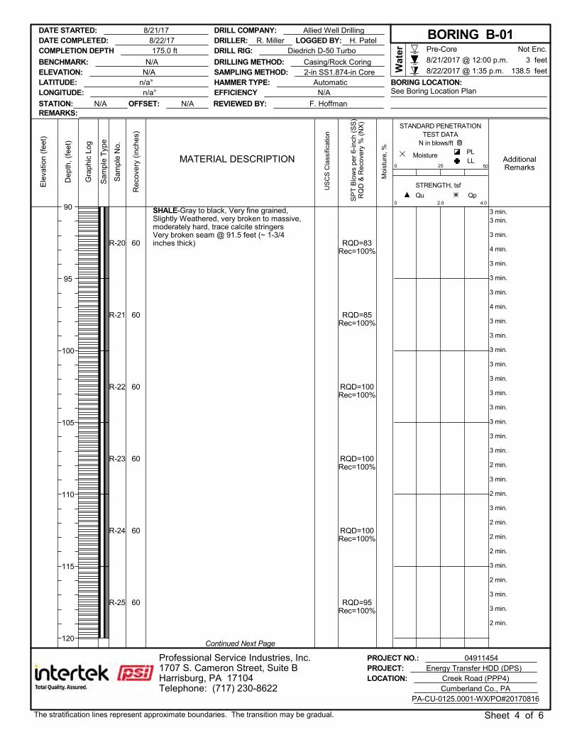
R-20
R-21
R-22
R-23
R-24
R-25
60
60
60
60
60
60
RQD=83Rec=100%
RQD=85Rec=100%
RQD=100Rec=100%
RQD=100Rec=100%
RQD=100Rec=100%
RQD=95Rec=100%
SHALE-Gray to black, Very fine grained,Slightly Weathered, very broken to massive,moderately hard, trace calcite stringersVery broken seam @ 91.5 feet (~ 1-3/4inches thick)
3 min.3 min.
3 min.
4 min.
3 min.
3 min.
3 min.
4 min.
3 min.
3 min.
3 min.
3 min.
3 min.
3 min.
3 min.
3 min.
3 min.
3 min.
2 min.
3 min.
2 min.
3 min.
2 min.
2 min.
2 min.
3 min.
2 min.
3 min.
3 min.
2 min.
PROJECT NO.: 04911454PROJECT: Energy Transfer HDD (DPS)
Dep
th, (
feet
)
STRENGTH, tsf
AdditionalRemarks
US
CS
Cla
ssifi
catio
n
0
Qp
Sam
ple
Typ
e
2.0
0
Moi
stur
e, %
MoistureMATERIAL DESCRIPTION
STANDARD PENETRATIONTEST DATA
N in blows/ft
Qu
Sam
ple
No.
Gra
phic
Log
50
PL
Ele
vatio
n (f
eet)
LL
4.0
25
Rec
over
y (in
ches
)
138.5 feet
Pre-Core
8/21/2017 @ 12:00 p.m.
8/22/2017 @ 1:35 p.m.
Continued Next Page
LATITUDE: n/a°LONGITUDE: n/a°
LOCATION: Creek Road (PPP4)
3 feet
Not Enc.
Wat
er
REMARKS:
DRILLER: R. Miller
Professional Service Industries, Inc.1707 S. Cameron Street, Suite BHarrisburg, PA 17104Telephone: (717) 230-8622 Cumberland Co., PA
PA-CU-0125.0001-WX/PO#20170816
SP
T B
low
s pe
r 6-
inch
(S
S)
RQ
D &
Rec
over
y %
(N
X)
SAMPLING METHOD: 2-in SS1.874-in Core
DATE STARTED: 8/21/17
BENCHMARK: N/A
The stratification lines represent approximate boundaries. The transition may be gradual. Sheet 4 of 6
DRILL COMPANY: Allied Well Drilling
STATION: N/A OFFSET: N/A
LOGGED BY: H. PatelCOMPLETION DEPTH 175.0 ft DRILL RIG: Diedrich D-50 Turbo
DRILLING METHOD: Casing/Rock CoringELEVATION: N/A
REVIEWED BY: F. Hoffman
EFFICIENCY N/A See Boring Location PlanHAMMER TYPE: Automatic BORING LOCATION:
90
95
100
105
110
115
120
DATE COMPLETED: 8/22/17 BORING B-01
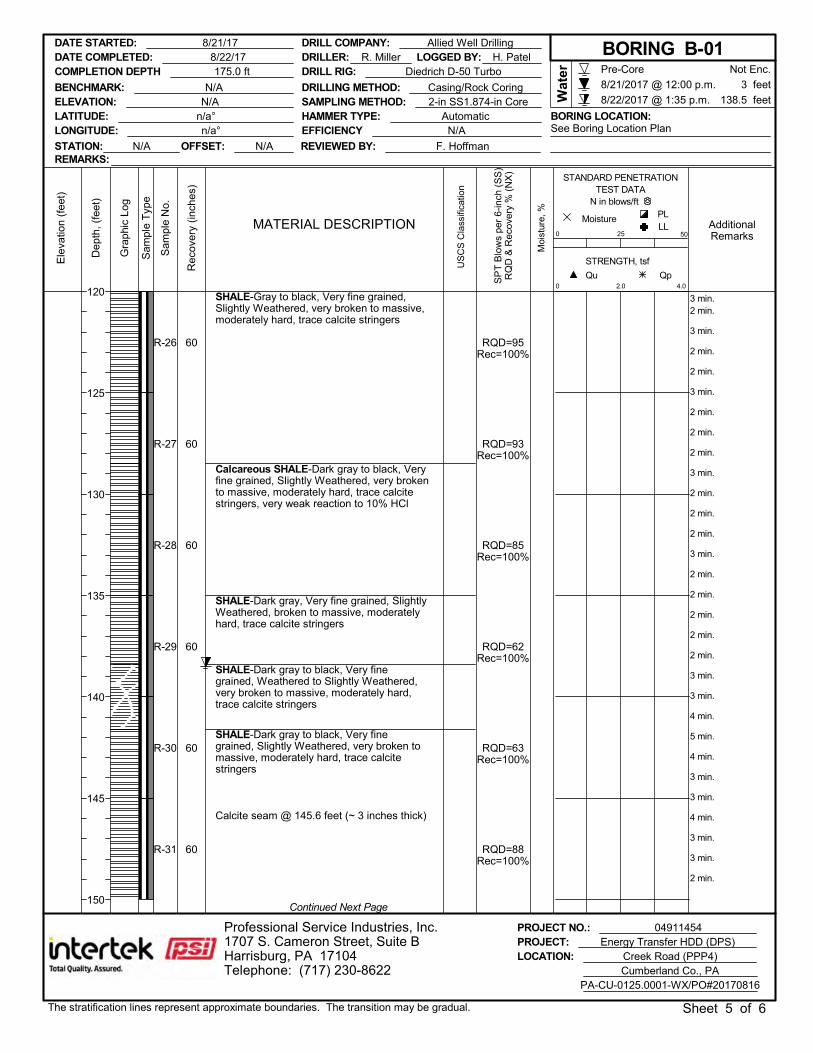
R-26
R-27
R-28
R-29
R-30
R-31
60
60
60
60
60
60
RQD=95Rec=100%
RQD=93Rec=100%
RQD=85Rec=100%
RQD=62Rec=100%
RQD=63Rec=100%
RQD=88Rec=100%
SHALE-Gray to black, Very fine grained,Slightly Weathered, very broken to massive,moderately hard, trace calcite stringers
Calcareous SHALE-Dark gray to black, Veryfine grained, Slightly Weathered, very brokento massive, moderately hard, trace calcitestringers, very weak reaction to 10% HCl
SHALE-Dark gray, Very fine grained, SlightlyWeathered, broken to massive, moderatelyhard, trace calcite stringers
SHALE-Dark gray to black, Very finegrained, Weathered to Slightly Weathered,very broken to massive, moderately hard,trace calcite stringers
SHALE-Dark gray to black, Very finegrained, Slightly Weathered, very broken tomassive, moderately hard, trace calcitestringers
Calcite seam @ 145.6 feet (~ 3 inches thick)
3 min.2 min.
3 min.
2 min.
2 min.
3 min.
2 min.
2 min.
2 min.
3 min.
2 min.
2 min.
2 min.
3 min.
2 min.
2 min.
2 min.
2 min.
2 min.
3 min.
3 min.
4 min.
5 min.
4 min.
3 min.
3 min.
4 min.
3 min.
3 min.
2 min.
PROJECT NO.: 04911454PROJECT: Energy Transfer HDD (DPS)
Dep
th, (
feet
)
STRENGTH, tsf
AdditionalRemarks
US
CS
Cla
ssifi
catio
n
0
Qp
Sam
ple
Typ
e
2.0
0
Moi
stur
e, %
MoistureMATERIAL DESCRIPTION
STANDARD PENETRATIONTEST DATA
N in blows/ft
Qu
Sam
ple
No.
Gra
phic
Log
50
PL
Ele
vatio
n (f
eet)
LL
4.0
25
Rec
over
y (in
ches
)
138.5 feet
Pre-Core
8/21/2017 @ 12:00 p.m.
8/22/2017 @ 1:35 p.m.
Continued Next Page
LATITUDE: n/a°LONGITUDE: n/a°
LOCATION: Creek Road (PPP4)
3 feet
Not Enc.
Wat
er
REMARKS:
DRILLER: R. Miller
Professional Service Industries, Inc.1707 S. Cameron Street, Suite BHarrisburg, PA 17104Telephone: (717) 230-8622 Cumberland Co., PA
PA-CU-0125.0001-WX/PO#20170816
SP
T B
low
s pe
r 6-
inch
(S
S)
RQ
D &
Rec
over
y %
(N
X)
SAMPLING METHOD: 2-in SS1.874-in Core
DATE STARTED: 8/21/17
BENCHMARK: N/A
The stratification lines represent approximate boundaries. The transition may be gradual. Sheet 5 of 6
DRILL COMPANY: Allied Well Drilling
STATION: N/A OFFSET: N/A
LOGGED BY: H. PatelCOMPLETION DEPTH 175.0 ft DRILL RIG: Diedrich D-50 Turbo
DRILLING METHOD: Casing/Rock CoringELEVATION: N/A
REVIEWED BY: F. Hoffman
EFFICIENCY N/A See Boring Location PlanHAMMER TYPE: Automatic BORING LOCATION:
120
125
130
135
140
145
150
DATE COMPLETED: 8/22/17 BORING B-01
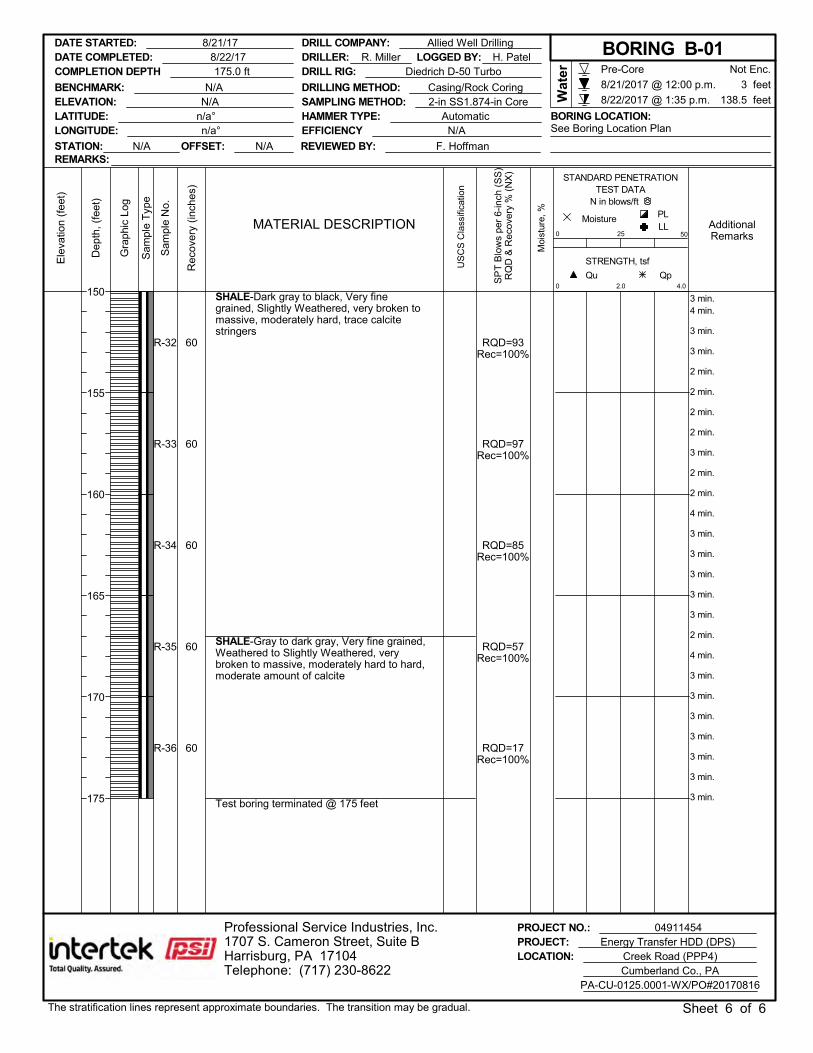
R-32
R-33
R-34
R-35
R-36
60
60
60
60
60
RQD=93Rec=100%
RQD=97Rec=100%
RQD=85Rec=100%
RQD=57Rec=100%
RQD=17Rec=100%
SHALE-Dark gray to black, Very finegrained, Slightly Weathered, very broken tomassive, moderately hard, trace calcitestringers
SHALE-Gray to dark gray, Very fine grained,Weathered to Slightly Weathered, verybroken to massive, moderately hard to hard,moderate amount of calcite
Test boring terminated @ 175 feet
3 min.4 min.
3 min.
3 min.
2 min.
2 min.
2 min.
2 min.
3 min.
2 min.
2 min.
4 min.
3 min.
3 min.
3 min.
3 min.
3 min.
2 min.
4 min.
3 min.
3 min.
3 min.
3 min.
3 min.
3 min.
3 min.
PROJECT NO.: 04911454PROJECT: Energy Transfer HDD (DPS)
Dep
th, (
feet
)
STRENGTH, tsf
AdditionalRemarks
US
CS
Cla
ssifi
catio
n
0
Qp
Sam
ple
Typ
e
2.0
0
Moi
stur
e, %
MoistureMATERIAL DESCRIPTION
STANDARD PENETRATIONTEST DATA
N in blows/ft
Qu
Sam
ple
No.
Gra
phic
Log
50
PL
Ele
vatio
n (f
eet)
LL
4.0
25
Rec
over
y (in
ches
)
138.5 feet
Pre-Core
8/21/2017 @ 12:00 p.m.
8/22/2017 @ 1:35 p.m.
LATITUDE: n/a°LONGITUDE: n/a°
LOCATION: Creek Road (PPP4)
3 feet
Not Enc.
Wat
er
REMARKS:
DRILLER: R. Miller
Professional Service Industries, Inc.1707 S. Cameron Street, Suite BHarrisburg, PA 17104Telephone: (717) 230-8622 Cumberland Co., PA
PA-CU-0125.0001-WX/PO#20170816
SP
T B
low
s pe
r 6-
inch
(S
S)
RQ
D &
Rec
over
y %
(N
X)
SAMPLING METHOD: 2-in SS1.874-in Core
DATE STARTED: 8/21/17
BENCHMARK: N/A
The stratification lines represent approximate boundaries. The transition may be gradual. Sheet 6 of 6
DRILL COMPANY: Allied Well Drilling
STATION: N/A OFFSET: N/A
LOGGED BY: H. PatelCOMPLETION DEPTH 175.0 ft DRILL RIG: Diedrich D-50 Turbo
DRILLING METHOD: Casing/Rock CoringELEVATION: N/A
REVIEWED BY: F. Hoffman
EFFICIENCY N/A See Boring Location PlanHAMMER TYPE: Automatic BORING LOCATION:
150
155
160
165
170
175
DATE COMPLETED: 8/22/17 BORING B-01
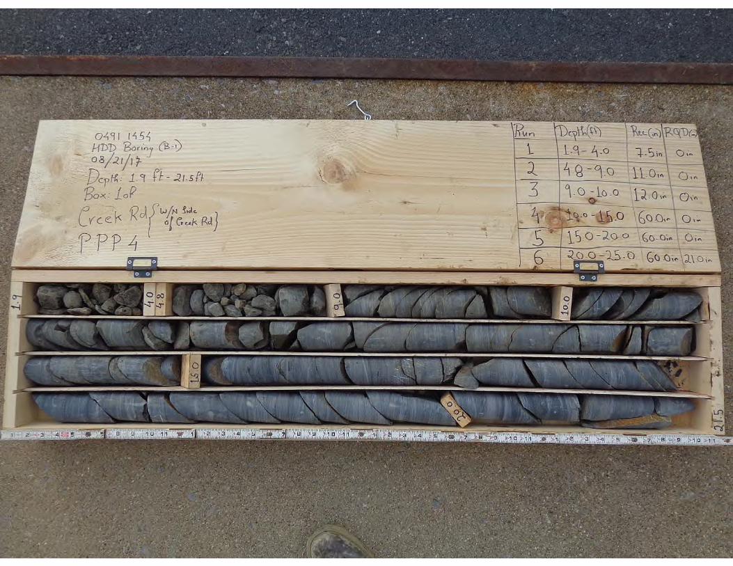
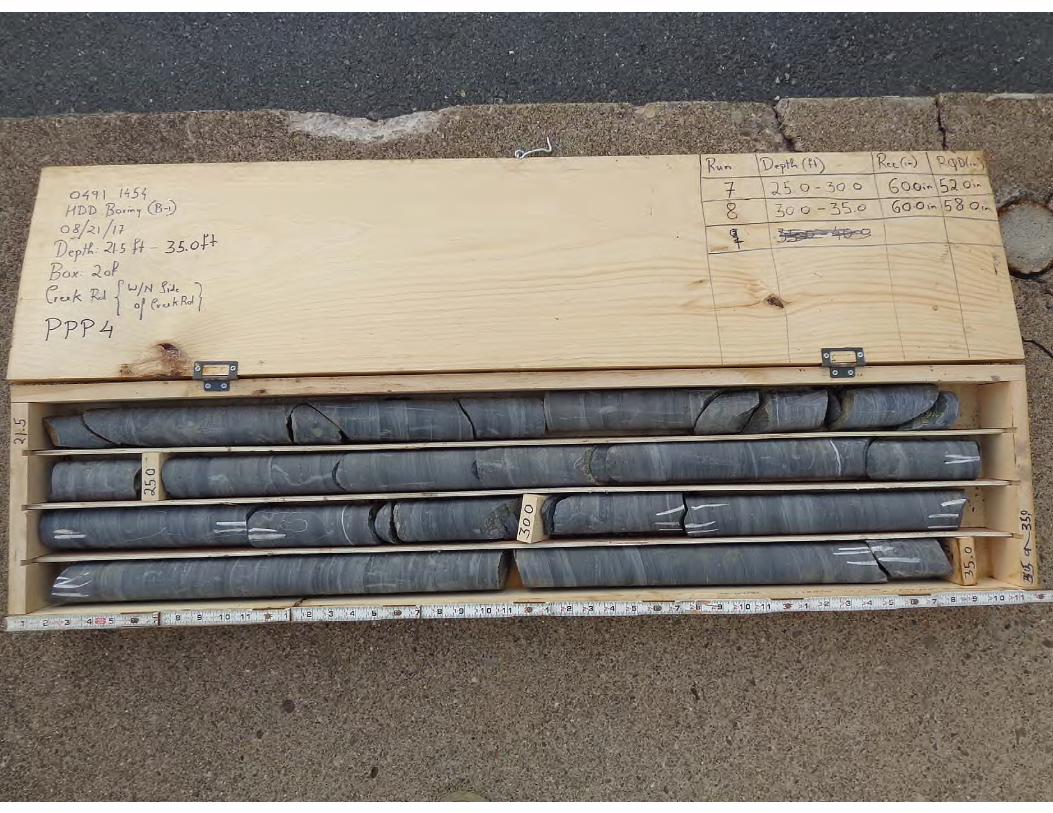
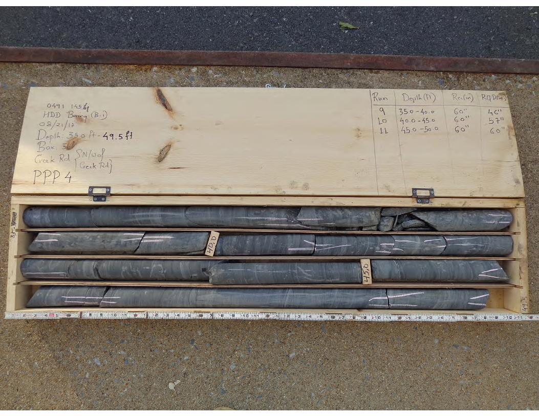
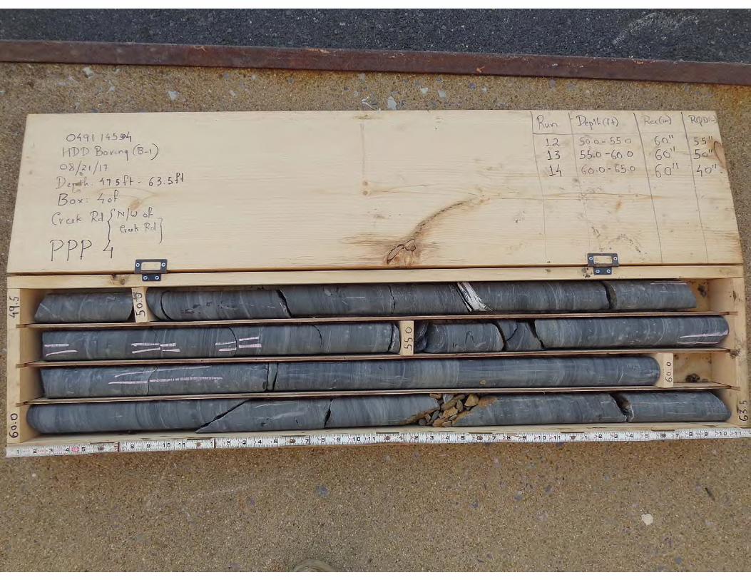
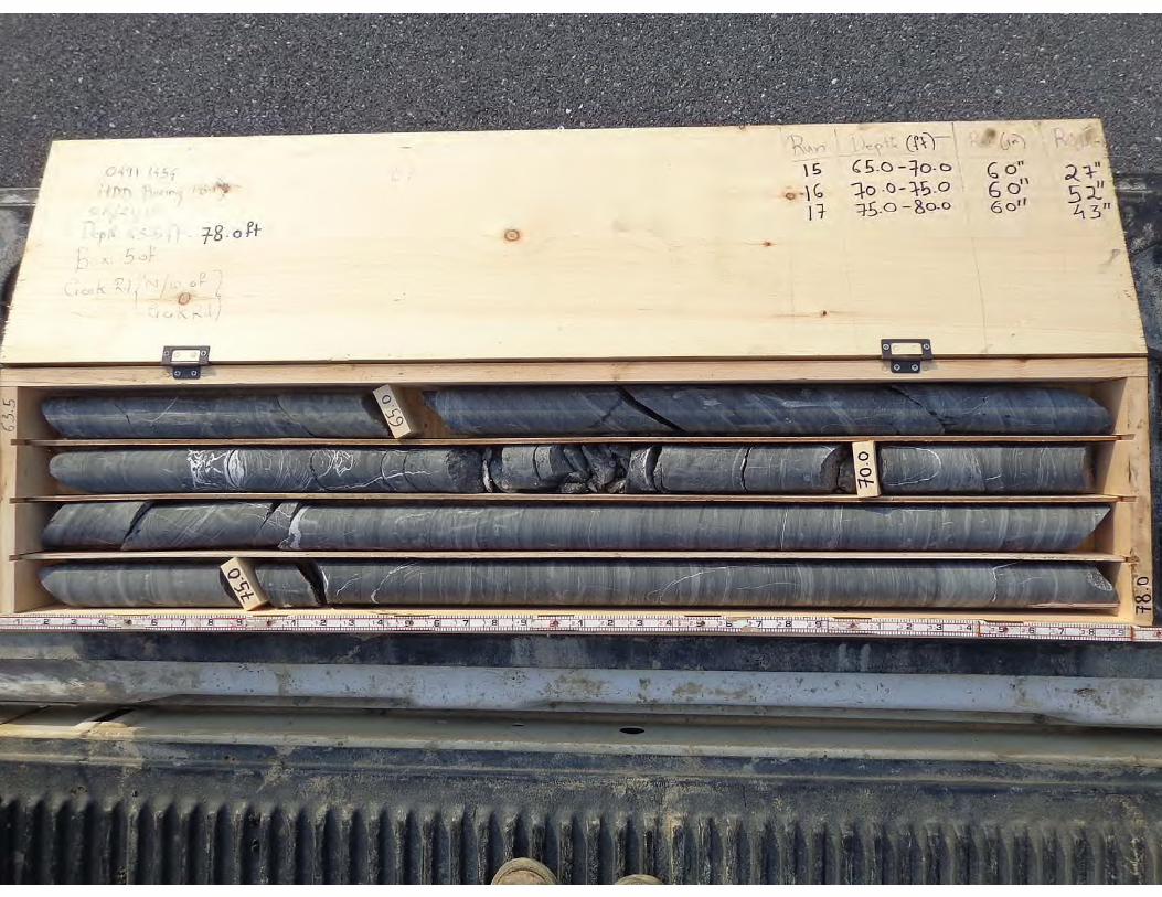
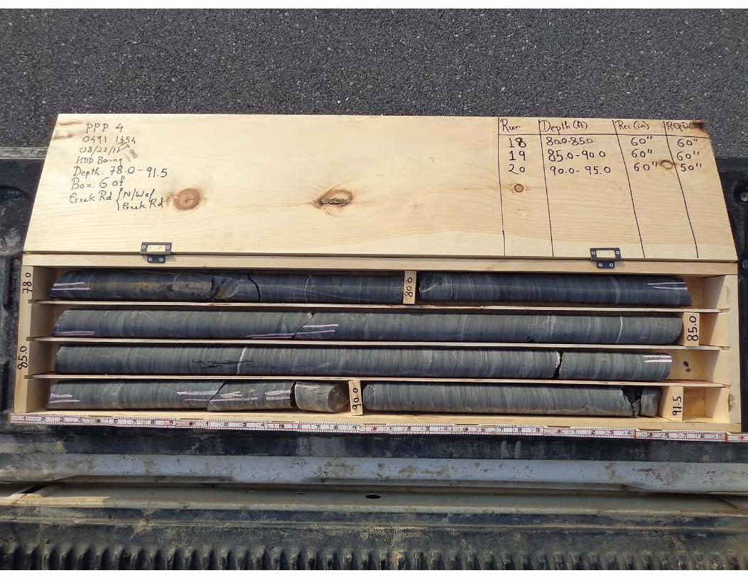
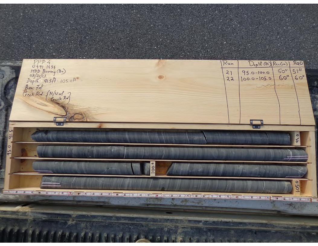
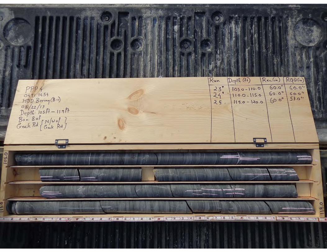
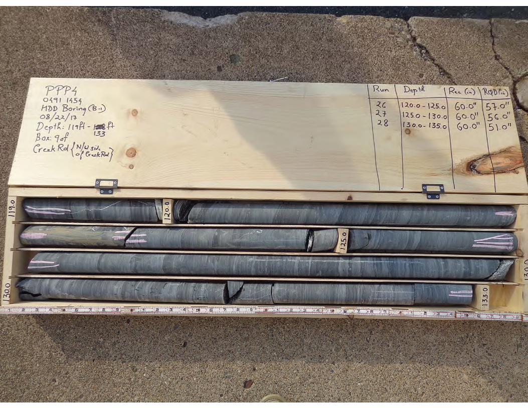
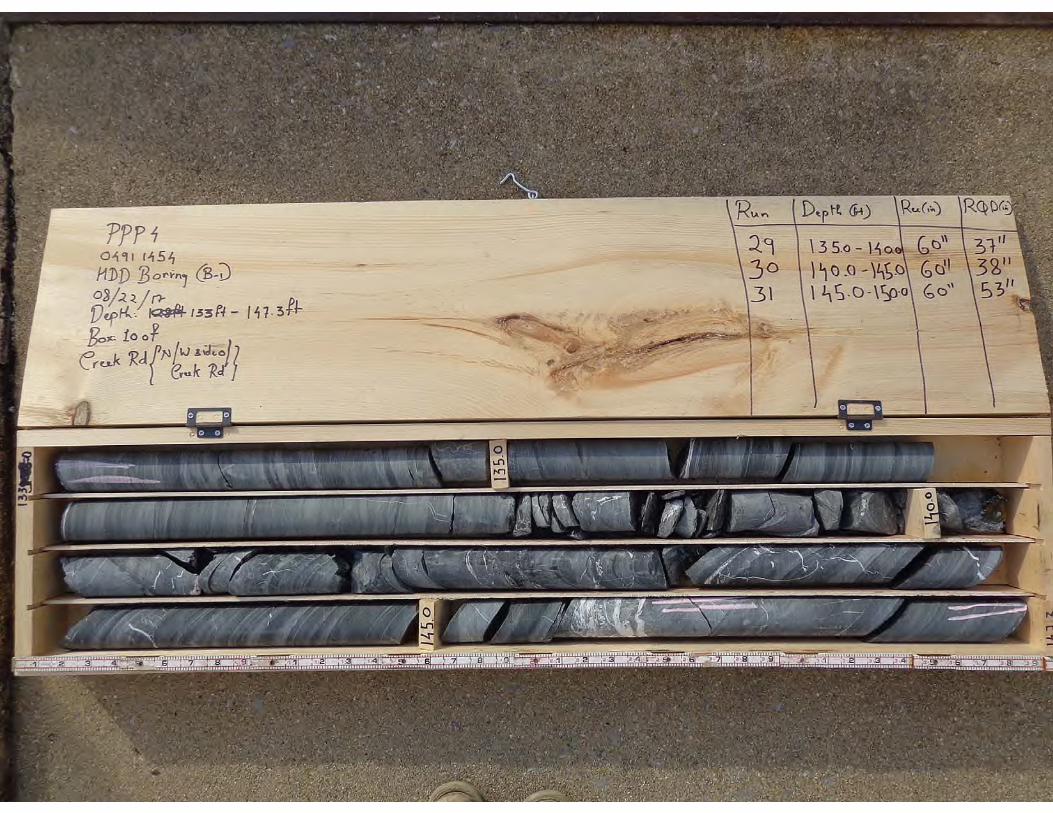
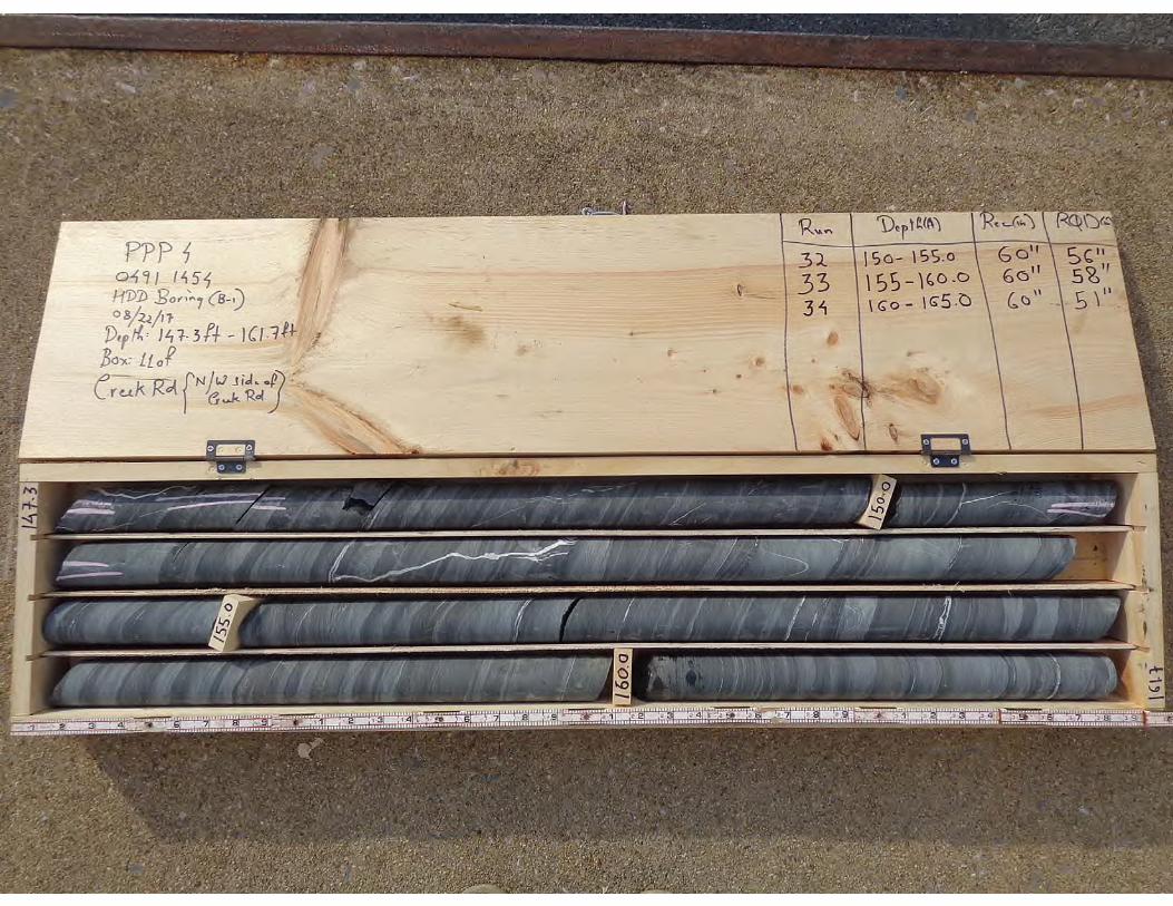
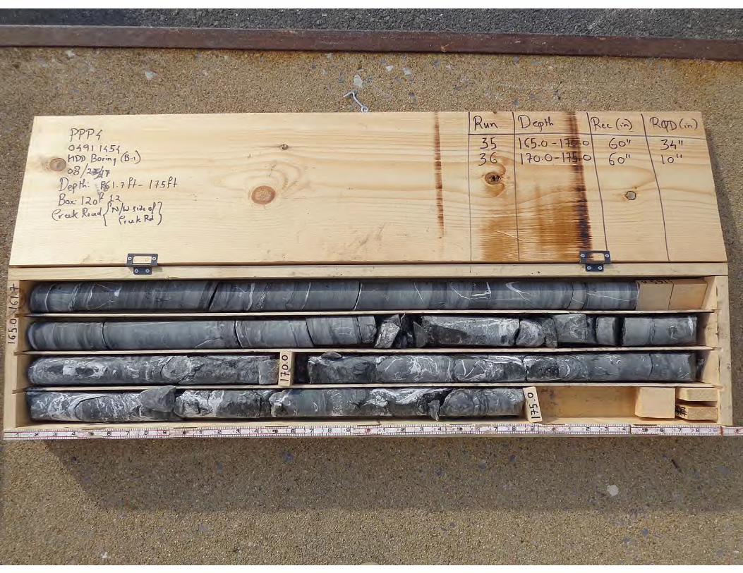
GENERAL NOTES
SAMPLE IDENTIFICATION
Page 1 of 2
The Unified Soil Classification System (USCS), AASHTO 1988 and ASTM designations D2487 and D-2488 areused to identify the encountered materials unless otherwise noted. Coarse-grained soils are defined as havingmore than 50% of their dry weight retained on a #200 sieve (0.075mm); they are described as: boulders,cobbles, gravel or sand. Fine-grained soils have less than 50% of their dry weight retained on a #200 sieve;they are defined as silts or clay depending on their Atterberg Limit attributes. Major constituents may be addedas modifiers and minor constituents may be added according to the relative proportions based on grain size.
Description
Flat:
Elongated:
Flat & Elongated:
Description
Angular:
Subangular:
Subrounded:
Rounded:
Criteria
Particles with width/thickness ratio > 3
Particles with length/width ratio > 3
Particles meet criteria for both flat and
elongated
Descriptive Term
Trace:
With:
Modifier:
Size Range
Over 300 mm (>12 in.)
75 mm to 300 mm (3 in. to 12 in.)
19 mm to 75 mm (¾ in. to 3 in.)
4.75 mm to 19 mm (No.4 to ¾ in.)
2 mm to 4.75 mm (No.10 to No.4)
0.42 mm to 2 mm (No.40 to No.10)
0.075 mm to 0.42 mm (No. 200 to No.40)
0.005 mm to 0.075 mm
<0.005 mm
Component
Boulders:
Cobbles:
Coarse-Grained Gravel:
Fine-Grained Gravel:
Coarse-Grained Sand:
Medium-Grained Sand:
Fine-Grained Sand:
Silt:
Clay:
ANGULARITY OF COARSE-GRAINED PARTICLESRELATIVE DENSITY OF COARSE-GRAINED SOILS
N - Blows/foot
0 - 4
4 - 10
10 - 30
30 - 50
50 - 80
80+
Relative Density
Very Loose
Loose
Medium Dense
Dense
Very Dense
Extremely Dense
RELATIVE PROPORTIONS OF FINES
% Dry Weight
< 5%
5% to 12%
>12%
Standard "N" penetration: Blows per foot of a 140 pound hammer falling 30 inches on a 2-inch O.D.Split-Spoon.A "N" penetration value corrected to an equivalent 60% hammer energy transfer efficiency (ETR)Unconfined compressive strength, TSFPocket penetrometer value, unconfined compressive strength, TSFMoisture/water content, %Liquid Limit, %Plastic Limit, %Plasticity Index = (LL-PL),%Dry unit weight, pcfApparent groundwater level at time noted
Criteria
Particles have sharp edges and relatively plane
sides with unpolished surfaces
Particles are similar to angular description, but have
rounded edges
Particles have nearly plane sides, but have
well-rounded corners and edges
Particles have smoothly curved sides and no edges
N:
N60:Qu:Qp:
w%:LL:PL:PI:
DD:
, ,
GRAIN-SIZE TERMINOLOGY PARTICLE SHAPE
SOIL PROPERTY SYMBOLS
Shelby Tube - 3" O.D., except where noted.
Rock Core
Texas Cone
Bulk Sample
Pressuremeter
Cone Penetrometer Testing withPore-Pressure Readings
DRILLING AND SAMPLING SYMBOLS
Solid Flight Auger - typically 4" diameterflights, except where noted.Hollow Stem Auger - typically 3¼" or 4¼ I.D.openings, except where noted.Mud Rotary - Uses a rotary head withBentonite or Polymer SlurryDiamond Bit Core SamplerHand AugerPower Auger - Handheld motorized auger
Split-Spoon - 1 3/8" I.D., 2" O.D., exceptwhere noted.
SFA:
HSA:
M.R.:
R.C.:H.A.:P.A.:
SS:
ST:
RC:
TC:
BS:
PM:
CPT-U:
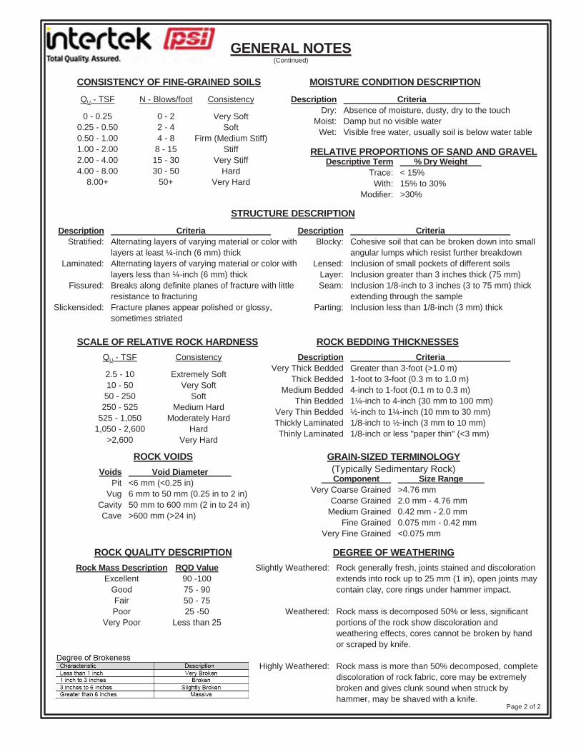
GENERAL NOTES
QU - TSF N - Blows/foot Consistency
0 - 22 - 44 - 8
8 - 1515 - 3030 - 50
50+
CriteriaAbsence of moisture, dusty, dry to the touchDamp but no visible waterVisible free water, usually soil is below water table
RELATIVE PROPORTIONS OF SAND AND GRAVEL% Dry Weight
< 15%15% to 30%>30%
Descriptive TermTrace:
With:Modifier:
0 - 0.250.25 - 0.500.50 - 1.001.00 - 2.002.00 - 4.004.00 - 8.00
8.00+
MOISTURE CONDITION DESCRIPTION
Page 2 of 2
CONSISTENCY OF FINE-GRAINED SOILS
DescriptionBlocky:
Lensed:Layer:Seam:
Parting:
DescriptionStratified:
Laminated:
Fissured:
Slickensided:
STRUCTURE DESCRIPTION
QU - TSF
Extremely SoftVery Soft
SoftMedium Hard
Moderately HardHard
Very Hard
SCALE OF RELATIVE ROCK HARDNESS ROCK BEDDING THICKNESSESConsistency
CriteriaAlternating layers of varying material or color withlayers at least ¼-inch (6 mm) thickAlternating layers of varying material or color withlayers less than ¼-inch (6 mm) thickBreaks along definite planes of fracture with littleresistance to fracturingFracture planes appear polished or glossy,sometimes striated
CriteriaGreater than 3-foot (>1.0 m)1-foot to 3-foot (0.3 m to 1.0 m)4-inch to 1-foot (0.1 m to 0.3 m)1¼-inch to 4-inch (30 mm to 100 mm)½-inch to 1¼-inch (10 mm to 30 mm)1/8-inch to ½-inch (3 mm to 10 mm)1/8-inch or less "paper thin" (<3 mm)
DescriptionDry:
Moist:Wet:
DescriptionVery Thick Bedded
Thick BeddedMedium Bedded
Thin BeddedVery Thin BeddedThickly LaminatedThinly Laminated
2.5 - 1010 - 50
50 - 250250 - 525
525 - 1,0501,050 - 2,600
>2,600
(Continued)
Component Very Coarse Grained
Coarse GrainedMedium Grained
Fine GrainedVery Fine Grained
GRAIN-SIZED TERMINOLOGY(Typically Sedimentary Rock)
ROCK VOIDSVoids
PitVug
CavityCave
Void Diameter <6 mm (<0.25 in)6 mm to 50 mm (0.25 in to 2 in)50 mm to 600 mm (2 in to 24 in)>600 mm (>24 in)
ROCK QUALITY DESCRIPTIONRQD Value
90 -10075 - 9050 - 7525 -50
Less than 25
Size Range >4.76 mm2.0 mm - 4.76 mm0.42 mm - 2.0 mm0.075 mm - 0.42 mm<0.075 mm
Rock generally fresh, joints stained and discolorationextends into rock up to 25 mm (1 in), open joints maycontain clay, core rings under hammer impact.
Rock mass is decomposed 50% or less, significantportions of the rock show discoloration andweathering effects, cores cannot be broken by handor scraped by knife.
Rock mass is more than 50% decomposed, completediscoloration of rock fabric, core may be extremelybroken and gives clunk sound when struck byhammer, may be shaved with a knife.
Rock Mass DescriptionExcellent
GoodFairPoor
Very Poor
DEGREE OF WEATHERINGSlightly Weathered:
Weathered:
Highly Weathered:
CriteriaCohesive soil that can be broken down into smallangular lumps which resist further breakdownInclusion of small pockets of different soilsInclusion greater than 3 inches thick (75 mm)Inclusion 1/8-inch to 3 inches (3 to 75 mm) thickextending through the sampleInclusion less than 1/8-inch (3 mm) thick
Very SoftSoft
Firm (Medium Stiff)Stiff
Very StiffHard
Very Hard
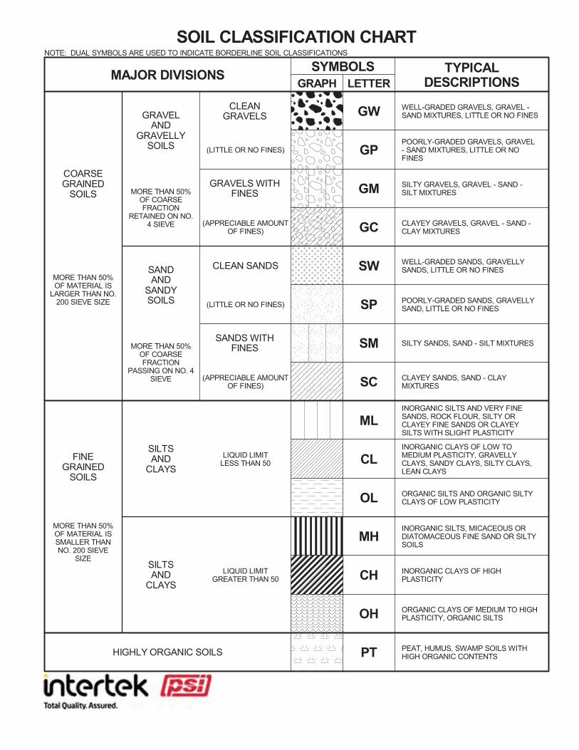
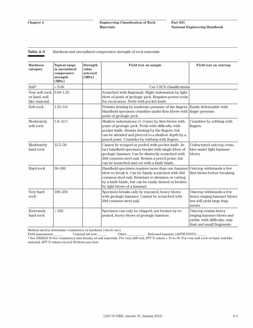
Part 631
National Engineering Handbook
Engineering Classification of Rock
Materials
Chapter 4
4–5(210–VI–NEH, Amend. 55, January 2012)
Hardness
category
Typical range
in unconfined
compressive
strength
(MPa)
Strength
value
selected
(MPa)
Field test on sample Field test on outcrop
Soil* < 0.60 Use USCS classifications
Very soft rock or hard, soil-like material
0.60–1.25 Scratched with fingernail. Slight indentation by light blow of point of geologic pick. Requires power tools for excavation. Peels with pocket knife.
Soft rock 1.25–5.0 Permits denting by moderate pressure of the fingers. Handheld specimen crumbles under firm blows with point of geologic pick.
Easily deformable with finger pressure.
Moderately soft rock
5.0–12.5 Shallow indentations (1–3 mm) by firm blows with point of geologic pick. Peels with difficulty with pocket knife. Resists denting by the fingers, but can be abraded and pierced to a shallow depth by a pencil point. Crumbles by rubbing with fingers.
Crumbles by rubbing with fingers.
Moderately hard rock
12.5–50 Cannot be scraped or peeled with pocket knife. In-tact handheld specimen breaks with single blow of geologic hammer. Can be distinctly scratched with 20d common steel nail. Resists a pencil point, but can be scratched and cut with a knife blade.
Unfractured outcrop crum-bles under light hammer blows.
Hard rock 50–100 Handheld specimen requires more than one hammer blow to break it. Can be faintly scratched with 20d common steel nail. Resistant to abrasion or cutting by a knife blade, but can be easily dented or broken by light blows of a hammer.
Outcrop withstands a few firm blows before breaking.
Very hard rock
100–250 Specimen breaks only by repeated, heavy blows with geologic hammer. Cannot be scratched with 20d common steel nail.
Outcrop withstands a few heavy ringing hammer blows but will yield large frag-ments.
Extremely hard rock
> 250 Specimen can only be chipped, not broken by re-peated, heavy blows of geologic hammer.
Outcrop resists heavy ringing hammer blows and yields, with difficulty, only dust and small fragments.
Table 4–3 Hardness and unconfined compressive strength of rock materials
Method used to determine consistency or hardness (check one): Field assessment: _____ Uniaxial lab test: _____ Other: __________ Rebound hammer (ASTM D5873): _____ * See NEH631.03 for consistency and density of soil materials. For very stiff soil, SPT N values = 15 to 30. For very soft rock or hard, soil-like material, SPT N values exceed 30 blows per foot.
CREEK ROAD/ CONODOGUINET CREEK CROSSING PADEP SECTION 105 PERMIT NO.S: E21-449
PA-CU-0125.0000-WX & PA-CU-0125.0000-WX-16 (SPLP HDD No. S2-0181)
ATTACHMENT 2
ORIGINAL AND REVISED HORIZONTAL DIRECTIONAL DRILL PLAN AND PROFILES
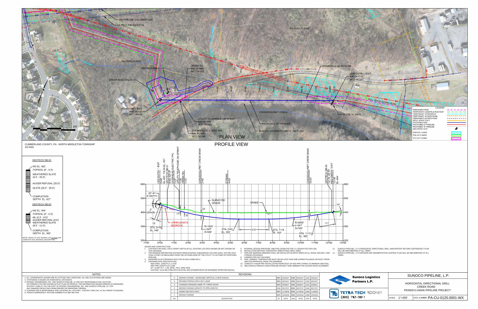
CREEK RD
N40.241986
W77.191014
HDD ENTRY / EXIT
N40.241716
W77.187247
EX PIPELINE COLUMBIA GAS
EX PIPELINE BUCKEYE
0+
00
1+
00
2+
00
3+
00
4+
00
5+
00
6+
00
7+
00
8+
00
9+
00
10+
00
11+
00
12+
00
12+
30
HDD ENTRY / EXIT
N40.242031
W77.191634
OVERHEAD ELECTRIC PPL
N40.241996
W77.191146
UTILITY TELEPHONE OH SPRINT
N40.241995
W77.191143
CREEK ROAD VALVE
GEOTECH SB-01
GEOTECH SB-02
200
300
400
500
600
200
300
400
500
600
-1+00 0+00 1+00 2+00 3+00 4+00 5+00 6+00 7+00 8+00 9+00 10+00 11+00 12+00 13+00
24'
15'
20° AT
5' DEPTH
111'
10°
STA. 0+14
EL. 449'
STA. 11+21
EL. 383'
GRADE
13'
212'STA. 7+74
EL. 353'
STA. 5+61
EL. 353'
SURVEYED
GRADE
23'
OV
ER
HE
AD
E
LE
CT
RIC
P
PL
1+
37
HD
D E
NT
RY
/ E
XIT
0+
00
EL.460', T
IE
-IN
E
L. 451'
HD
D E
NT
RY
/ E
XIT
12+
30
EL.404'
CO
NO
DO
GU
IN
ET
C
RE
EK
B
AN
K
10+
61
CR
EE
K R
D
1+
74
UT
ILIT
Y T
ELE
PH
ON
E O
H S
PR
IN
T
1+
38
CO
NO
DO
GU
IN
ET
C
RE
EK
B
AN
K
2+
92
ST
RE
AM
4+
83
2°
GRADE
20'
APPROXIMATE
BEDROCK
GE
OT
EC
H S
B-02
12+
19, 20' R
T
GE
OT
EC
H S
B-01
0+
52, 53' LT
R=2000'
L=347'
S=349'
R=1600'
L=547'
S=559'
PA-CU-0125.0000
CONODOGUINET CREEK
0
FEET
100 100 200
PROPOSED 16" PIPELINE
PROPOSED 20" PIPELINE
LEGEND
PERMANENT ROW
TEMPORARY CONSTRUCTION ROW
TEMPORARY WORKSPACE
TEMPORARY ACCESS ROAD
PERMANENT ACCESS ROAD
SPOIL SPACE ONLY
PROPOSED HDD
PROPOSED 20" PIPELINE
PROPOSED 16" PIPELINE
HDD ENTRY-EXIT
PEM WETLANDS
PSS WETLANDS
PFO WETLANDS
PLAN VIEW
PROFILE VIEW
NO. DESCRIPTION DATEBY CHK DATE
REVISIONS
DATEAPP
NOTES Sunoco LogisticsPartners L.P.
HORIZONTAL DIRECTIONAL DRILL
SUNOCO PIPELINE, L.P.
1. ALL COORDINATES SHOWN ARE IN LATITUDE AND LONGITUDE. ALL MSL ELEVATIONS ARE NAD83
2. STATIONING IS BASED ON HORIZONTAL DISTANCES.
3. ROONEY ENGINEERING, INC. AND SUNOCO PIPELINE, LP ARE NOT RESPONSIBLE FOR LOCATION
OF FOREIGN UTILITIES SHOWN IN PLOT PLAN OR PROFILE. THE INFORMATION SHOWN HEREON IS FURNISHED
WITHOUT LIABILITY ON THE PART OF ROONEY ENGINEERING, INC. AND SUNOCO PIPELINE, LP, FOR
ANY DAMAGES RESULTING FROM ERRORS OR OMISSIONS THEREIN.
4. CONTRACTOR IS RESPONSIBLE FOR LOCATING ALL UTILITIES. CONTACT ONE CALL AT 811 PRIOR TO DIGGING.
5. SUNOCO EMERGENCY HOTLINE NUMBER IS #1-800-786-7440.
PENNSYLVANIA PIPELINE PROJECT
DESIGN AND CONSTRUCTION:
1. CONTRACTOR SHALL FIELD VERIFY DEPTH OF ALL EXISTING UTILITIES SHOWN OR NOT SHOWN ON
THIS DRAWING.
2. THE MINIMUM SEPARATION DISTANCE FROM EXISTING SUBSURFACE UTILITIES SHALL NOT BE LESS
THAN 10 FEET AS MEASURED FROM THE OUTSIDE EDGE OF THE UTILITY TO OUTSIDE OF PROPOSED
PIPELINE.
3. DESIGNED IN ACCORDANCE WITH CFR 49 195 & ASME B31.4
4. CROSSING PIPE SPECIFICATION:
HDD HORZ. LENGTH (L=):
HDD PIPE LENGTH (S=):
20" x 0.456" W.T., X-65, API5L, PSL2, ERW, BFW
COATING: 14-16 MILS FBE WITH 30-35 MIL ARO (POWERCRETE OR ENGINEER APPROVED EQUAL)
5. INTERNAL DESIGN PRESSURE 1480 PSIG (SEAM FACTOR 1.0, DESIGH FACTOR 0.50).
6. INSTALLATION METHOD: HORIZONTAL DIRECTIONAL DRILL (HDD).
7. PIPELINE WARNING MARKERS SHALL BE INSTALLED ON BOTH SIDES OF ALL ROAD, RAILWAY, AND
STREAM CROSSINGS.
8. CARRIER PIPE NOT ENCASED.
9. PIPE / AMBIENT TEMPERATURE MUST BE NO LESS THAN 30°F DURING PULLBACK WITHOUT PRIOR
WRITTEN APPROVAL FROM THE ENGINEER.
10. CONDUCT 4-HOUR PRE-INSTALLATION HYDROTEST OF HDD PIPE STRING TO MINIMUM 1850 PSIG.
11. SEE SUNOCO PENNSYLVANIA PIPELINE PROJECT ESRI WEBMAP FOR ACCESS ROAD ALIGNMENT.
12. SUNOCO PIPELINE, L.P.'S HORIZONTAL DIRECTIONAL DRILL INADVERTENT RETURN CONTINGENCY PLAN
WILL BE IMPLEMENTED AT ALL TIMES.
13. SUNOCO PIPELINE, L.P.'S EROSION AND SEDIMENTATION CONTROL PLAN WILL BE IMPLEMENTED AT ALL
TIMES.
CREEK ROAD
1"=200'
PA-CU-0125.0001-WX
CUMBERLAND COUNTY, PA - NORTH MIDDLETON TOWNSHIP
S2-0181
1 DESIGN CHANGEMRS RMB AAW10/10/16 10/10/1610/10/16
6 DESIGN CHANGE - INCREASED VERTICAL CURVE RADIUSMRS RMB CAG04/24/17 04/24/17 04/24/17
5REVISED PROFILE WITH 2017 LIDAR
MRS RMB CAG03/14/17 03/14/17 03/14/17
4 CHANGED DRAWING NAME TO "CREEK ROAD"MRS RMB CAG03/06/17 03/06/17 03/06/17
3 DESIGN CHANGE (UPDATE TO PIPE LENGTH)DLM RMB CAG02/17/17 02/17/17 02/17/17
2ADDED GEOTECH INFO
MRS RMB AAW11/28/16 11/28/16 11/28/16
1230'
1246'
PA-CU-0126.0000
P
U
L
L
B
A
C
K
A
L
O
N
G
R
O
W
SUNOCO EASEMENT LIMITS - NOT LOD
NOTE: REFER TO TEST BORING LOG S2-0181 FOR
COMPLETE SOIL MATERIAL DESCRIPTION
GEOTECH SB-01
-NG EL. 462'
-TOPSOIL (0' - 0.3')
-COMPLETION
DEPTH EL. 427'
-WEATHERED SLATE
(0.3' - 25.0')
-AUGER REFUSAL (25.0')
-SLATE (25.0' - 35.0')
GEOTECH SB-02
-NG EL. 404'
-TOPSOIL (0' - 0.3')
-COMPLETION
DEPTH EL. 393'
-ML (0.3' - 8.0')
-WEATHERED SLATE
(8.0' - 11.0')
-AUGER REFUSAL (9.0')
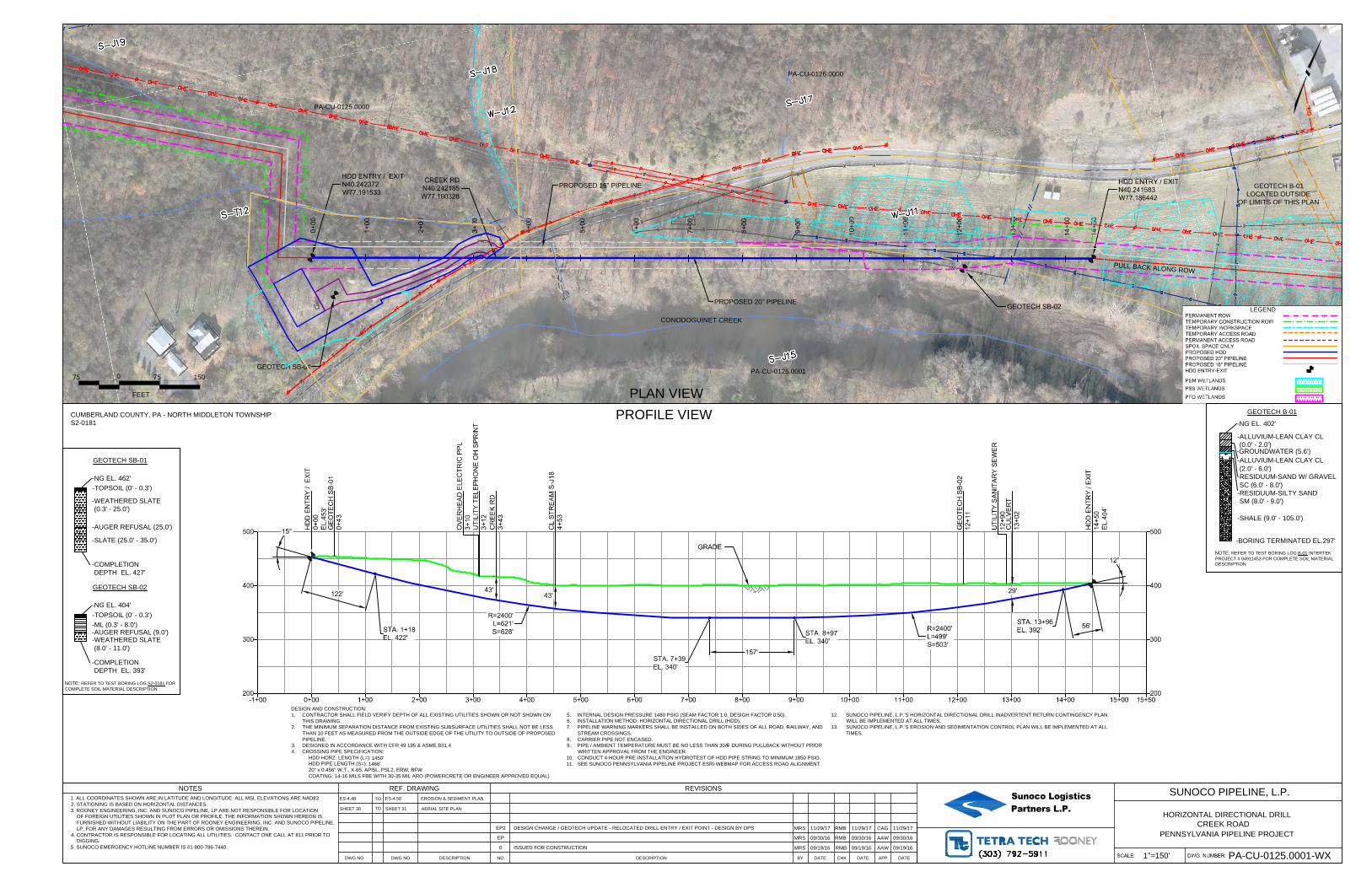
CREEK RD
N40.242185
W77.190328
0+
00
1+
00
2+
00
3+
00
4+
00
5+
00
6+
00
7+
00
8+
00
9+
00
10+
00
11+
00
12+
00
13+
00
14+
00
14+
50
HDD ENTRY / EXIT
N40.242372
W77.191533
GEOTECH SB-01
GEOTECH SB-02
HDD ENTRY / EXIT
N40.241583
W77.186442
200
300
400
500
200
300
400
500
-1+00 0+00 1+00 2+00 3+00 4+00 5+00 6+00 7+00 8+00 9+00 10+00 11+00 12+00 13+00 14+00 15+00 15+50
122'
56'
12°
STA. 1+18
EL. 422'
STA. 13+96
EL. 392'
GRADE
157'
STA. 8+97
EL. 340'
STA. 7+39
EL. 340'
43'
CR
EE
K R
D
3+
43
OV
ER
HE
AD
E
LE
CT
RIC
P
PL
3+
10
UT
ILIT
Y T
ELE
PH
ON
E O
H S
PR
IN
T
3+
12
HD
D E
NT
RY
/ E
XIT
0+
00
EL.453'
HD
D E
NT
RY
/ E
XIT
14+
50
EL.404'
43'
15°
GE
OT
EC
H S
B-02
12+
11
GE
OT
EC
H S
B-01
0+
43
CL S
TR
EA
M S
-J18
4+
53
CU
LV
ER
T
13+
02
UT
ILIT
Y S
AN
IT
AR
Y S
EW
ER
12+
90
29'
R=2400'
L=621'
S=628'
R=2400'
L=499'
S=503'
PA-CU-0125.0000
CONODOGUINET CREEK
0
FEET
75 75 150
PROPOSED 20" PIPELINE
LEGEND
PERMANENT ROW
TEMPORARY CONSTRUCTION ROW
TEMPORARY WORKSPACE
TEMPORARY ACCESS ROAD
PERMANENT ACCESS ROAD
SPOIL SPACE ONLY
PROPOSED HDD
PROPOSED 20" PIPELINE
PROPOSED 16" PIPELINE
HDD ENTRY-EXIT
PEM WETLANDS
PSS WETLANDS
PFO WETLANDS
PLAN VIEW
PROFILE VIEW
Sunoco LogisticsPartners L.P.
HORIZONTAL DIRECTIONAL DRILL
SUNOCO PIPELINE, L.P.
PENNSYLVANIA PIPELINE PROJECT
DESIGN AND CONSTRUCTION:
1. CONTRACTOR SHALL FIELD VERIFY DEPTH OF ALL EXISTING UTILITIES SHOWN OR NOT SHOWN ON
THIS DRAWING.
2. THE MINIMUM SEPARATION DISTANCE FROM EXISTING SUBSURFACE UTILITIES SHALL NOT BE LESS
THAN 10 FEET AS MEASURED FROM THE OUTSIDE EDGE OF THE UTILITY TO OUTSIDE OF PROPOSED
PIPELINE.
3. DESIGNED IN ACCORDANCE WITH CFR 49 195 & ASME B31.4
4. CROSSING PIPE SPECIFICATION:
HDD HORZ. LENGTH (L=):
HDD PIPE LENGTH (S=):
20" x 0.456" W.T., X-65, API5L, PSL2, ERW, BFW
COATING: 14-16 MILS FBE WITH 30-35 MIL ARO (POWERCRETE OR ENGINEER APPROVED EQUAL)
5. INTERNAL DESIGN PRESSURE 1480 PSIG (SEAM FACTOR 1.0, DESIGH FACTOR 0.50).
6. INSTALLATION METHOD: HORIZONTAL DIRECTIONAL DRILL (HDD).
7. PIPELINE WARNING MARKERS SHALL BE INSTALLED ON BOTH SIDES OF ALL ROAD, RAILWAY, AND
STREAM CROSSINGS.
8. CARRIER PIPE NOT ENCASED.
9. PIPE / AMBIENT TEMPERATURE MUST BE NO LESS THAN 30°F DURING PULLBACK WITHOUT PRIOR
WRITTEN APPROVAL FROM THE ENGINEER.
10. CONDUCT 4-HOUR PRE-INSTALLATION HYDROTEST OF HDD PIPE STRING TO MINIMUM 1850 PSIG.
11. SEE SUNOCO PENNSYLVANIA PIPELINE PROJECT ESRI WEBMAP FOR ACCESS ROAD ALIGNMENT.
12. SUNOCO PIPELINE, L.P.'S HORIZONTAL DIRECTIONAL DRILL INADVERTENT RETURN CONTINGENCY PLAN
WILL BE IMPLEMENTED AT ALL TIMES.
13. SUNOCO PIPELINE, L.P.'S EROSION AND SEDIMENTATION CONTROL PLAN WILL BE IMPLEMENTED AT ALL
TIMES.
PA-CU-0126.0000
PU
LL B
AC
K A
LO
NG
RO
W
NOTE: REFER TO TEST BORING LOG S2-0181 FOR
COMPLETE SOIL MATERIAL DESCRIPTION
GEOTECH SB-01
-NG EL. 462'
-TOPSOIL (0' - 0.3')
-COMPLETION
DEPTH EL. 427'
-WEATHERED SLATE
(0.3' - 25.0')
-AUGER REFUSAL (25.0')
-SLATE (25.0' - 35.0')
GEOTECH SB-02
-NG EL. 404'
-TOPSOIL (0' - 0.3')
-COMPLETION
DEPTH EL. 393'
-ML (0.3' - 8.0')
-WEATHERED SLATE
(8.0' - 11.0')
-AUGER REFUSAL (9.0')
PA-CU-0125.0001
PROPOSED 16" PIPELINE
GEOTECH B-01
-NG EL. 402'
-BORING TERMINATED EL.297'
-SHALE (9.0' - 105.0')
NOTE: REFER TO TEST BORING LOG B-01 INTERTEK
PROJECT # 04911453 FOR COMPLETE SOIL MATERIAL
DESCRIPTION
-ALLUVIUM-LEAN CLAY CL
(0.0' - 2.0')
-RESIDUUM-SAND W/ GRAVEL
SC (6.0' - 8.0')
-ALLUVIUM-LEAN CLAY CL
(2.0' - 6.0')
-RESIDUUM-SILTY SAND
SM (8.0' - 9.0')
-GROUNDWATER (5.6')
GEOTECH B-01
LOCATED OUTSIDE
OF LIMITS OF THIS PLAN
CREEK ROAD
1"=150'
PA-CU-0125.0001-WX
CUMBERLAND COUNTY, PA - NORTH MIDDLETON TOWNSHIP
S2-0181
1450'
1466'
REF. DRAWING
EROSION & SEDIMENT PLAN
AERIAL SITE PLAN
NO. DESCRIPTION DATEBY CHK DATE
REVISIONS
DATEAPP
NOTES
1. ALL COORDINATES SHOWN ARE IN LATITUDE AND LONGITUDE. ALL MSL ELEVATIONS ARE NAD83
2. STATIONING IS BASED ON HORIZONTAL DISTANCES.
3. ROONEY ENGINEERING, INC. AND SUNOCO PIPELINE, LP ARE NOT RESPONSIBLE FOR LOCATION
OF FOREIGN UTILITIES SHOWN IN PLOT PLAN OR PROFILE. THE INFORMATION SHOWN HEREON IS
FURNISHED WITHOUT LIABILITY ON THE PART OF ROONEY ENGINEERING, INC. AND SUNOCO PIPELINE,
LP, FOR ANY DAMAGES RESULTING FROM ERRORS OR OMISSIONS THEREIN.
4. CONTRACTOR IS RESPONSIBLE FOR LOCATING ALL UTILITIES. CONTACT ONE CALL AT 811 PRIOR TO
DIGGING.
5. SUNOCO EMERGENCY HOTLINE NUMBER IS #1-800-786-7440.
TO
TO
DWG NO DWG NO DESCRIPTION
09/19/160 ISSUED FOR CONSTRUCTION
MRS RMB AAW09/19/1609/19/16
09/30/16
ES-4.48
SHEET 31
EP2MRS RMB CAG
ES-4.50
11/29/17
EP MRS RMB AAW09/30/16
SHEET 30
09/30/16
DESIGN CHANGE / GEOTECH UPDATE - RELOCATED DRILL ENTRY / EXIT POINT - DESIGN BY DPS11/29/17 11/29/17
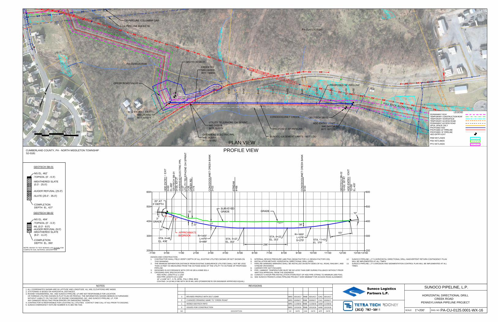
CREEK RD
N40.242009
W77.190950
HDD ENTRY / EXIT
N40.241734
W77.187113
EX PIPELINE COLUMBIA GAS
EX PIPELINE BUCKEYE
0+
00
1+
00
2+
00
3+
00
4+
00
5+
00
6+
00
7+
00
8+
00
9+
00
10
+0
0
11
+0
0
12
+0
0
12
+5
0
HDD ENTRY / EXIT
N40.242054
W77.191571
OVERHEAD ELECTRIC PPL
N40.242019
W77.191082
UTILITY TELEPHONE OH SPRINT
N40.242018
W77.191079
CREEK ROAD VALVE
GEOTECH SB-01
GEOTECH SB-02
200
300
400
500
600
200
300
400
500
600
-1+00 0+00 1+00 2+00 3+00 4+00 5+00 6+00 7+00 8+00 9+00 10+00 11+00 12+00 13+0013+50
38'
51'
20° AT
5' DEPTH
151'
10°
STA. 0+48
EL. 438'
STA. 11+01
EL. 378'
GRADE
15'
296'
STA. 8+23
EL. 353'
STA. 5+27
EL. 353'
SURVEYED
GRADE
27'
OV
ER
HE
AD
E
LE
CT
RIC
P
PL
1+
37
HD
D E
NT
RY
/ E
XIT
0+
00
EL
.4
60
'
HD
D E
NT
RY
/ E
XIT
12
+5
0
EL
.4
05
'
CR
EE
K R
D
1+
74
CO
NO
DO
GU
IN
ET
C
RE
EK
B
AN
K
3+
03
ST
RE
AM
4+
66
CO
NO
DO
GU
IN
ET
C
RE
EK
B
AN
K
9+
33
UT
IL
IT
Y T
EL
EP
HO
NE
O
H S
PR
IN
T
1+
38
22'
R=1600'
L=278'
S=279'
3°
GRADE
R=1400'
L=479'
S=489'
GE
OT
EC
H S
B-0
2
12
+0
2, 3
0' R
T
GE
OT
EC
H S
B-0
1
0+
35
, 4
3' L
T
APPROXIMATE
BEDROCK
PA-CU-0125.0000
CONODOGUINET CREEK
0
FEET
100 100 200
PROPOSED 16" PIPELINE
PROPOSED 20" PIPELINE
LEGEND
PERMANENT ROW
TEMPORARY CONSTRUCTION ROW
TEMPORARY WORKSPACE
TEMPORARY ACCESS ROAD
PERMANENT ACCESS ROAD
SPOIL SPACE ONLY
PROPOSED HDD
PROPOSED 20" PIPELINE
PROPOSED 16" PIPELINE
HDD ENTRY-EXIT
PEM WETLANDS
PSS WETLANDS
PFO WETLANDS
PLAN VIEW
PROFILE VIEW
NO. DESCRIPTION DATEBY CHK DATE
REVISIONS
DATEAPP
NOTES Sunoco LogisticsPartners L.P.
HORIZONTAL DIRECTIONAL DRILL
SUNOCO PIPELINE, L.P.
1. ALL COORDINATES SHOWN ARE IN LATITUDE AND LONGITUDE. ALL MSL ELEVATIONS ARE NAD83
2. STATIONING IS BASED ON HORIZONTAL DISTANCES.
3. ROONEY ENGINEERING, INC. AND SUNOCO PIPELINE, LP ARE NOT RESPONSIBLE FOR LOCATION
OF FOREIGN UTILITIES SHOWN IN PLOT PLAN OR PROFILE. THE INFORMATION SHOWN HEREON IS FURNISHED
WITHOUT LIABILITY ON THE PART OF ROONEY ENGINEERING, INC. AND SUNOCO PIPELINE, LP, FOR
ANY DAMAGES RESULTING FROM ERRORS OR OMISSIONS THEREIN.
4. CONTRACTOR IS RESPONSIBLE FOR LOCATING ALL UTILITIES. CONTACT ONE CALL AT 811 PRIOR TO DIGGING.
5. SUNOCO EMERGENCY HOTLINE NUMBER IS #1-800-786-7440.
PENNSYLVANIA PIPELINE PROJECT
DESIGN AND CONSTRUCTION:
1. CONTRACTOR SHALL FIELD VERIFY DEPTH OF ALL EXISTING UTILITIES SHOWN OR NOT SHOWN ON
THIS DRAWING.
2. THE MINIMUM SEPARATION DISTANCE FROM EXISTING SUBSURFACE UTILITIES SHALL NOT BE LESS
THAN 10 FEET AS MEASURED FROM THE OUTSIDE EDGE OF THE UTILITY TO OUTSIDE OF PROPOSED
PIPELINE.
3. DESIGNED IN ACCORDANCE WITH CFR 49 195 & ASME B31.4
4. CROSSING PIPE SPECIFICATION:
HDD HORZ. LENGTH (L=):
HDD PIPE LENGTH (S=):
16" x 0.438" W.T., X-70, API5L, PSL2, ERW, BFW
COATING: 14-16 MILS FBE WITH 30-35 MIL ARO (POWERCRETE OR ENGINEER APPROVED EQUAL)
5. INTERNAL DESIGN PRESSURE 1480 PSIG (SEAM FACTOR 1.0, DESIGH FACTOR 0.50).
6. INSTALLATION METHOD: HORIZONTAL DIRECTIONAL DRILL (HDD).
7. PIPELINE WARNING MARKERS SHALL BE INSTALLED ON BOTH SIDES OF ALL ROAD, RAILWAY, AND
STREAM CROSSINGS.
8. CARRIER PIPE NOT ENCASED.
9. PIPE / AMBIENT TEMPERATURE MUST BE NO LESS THAN 30°F DURING PULLBACK WITHOUT PRIOR
WRITTEN APPROVAL FROM THE ENGINEER.
10. CONDUCT 4-HOUR PRE-INSTALLATION HYDROTEST OF HDD PIPE STRING TO MINIMUM 1850 PSIG.
11. SEE SUNOCO PENNSYLVANIA PIPELINE PROJECT ESRI WEBMAP FOR ACCESS ROAD ALIGNMENT.
12. SUNOCO PIPELINE, L.P.'S HORIZONTAL DIRECTIONAL DRILL INADVERTENT RETURN CONTINGENCY PLAN
WILL BE IMPLEMENTED AT ALL TIMES.
13. SUNOCO PIPELINE, L.P.'S EROSION AND SEDIMENTATION CONTROL PLAN WILL BE IMPLEMENTED AT ALL
TIMES.
CREEK ROAD
1"=200'
PA-CU-0125.0001-WX-16
CUMBERLAND COUNTY, PA - NORTH MIDDLETON TOWNSHIP
S2-0181
0 ISSUED FOR CONSTRUCTION MRS RMB AAW10/10/16 10/10/1610/10/16
3 REVISED PROFILE WITH 2017 LIDAR MRS RMB CAG03/14/17 03/14/17 03/14/17
2 CHANGED DRAWING NAME TO "CREEK ROAD"MRS RMB CAG03/06/17 03/06/17 03/06/17
1 ADDED GEOTECH INFOMRS RMB AAW11/28/16 11/28/16 11/28/16
1250'
1266'
PA-CU-0126.0000
P
U
L
L
B
A
C
K
A
L
O
N
G
R
O
W
SUNOCO EASEMENT LIMITS - NOT LOD
NOTE: REFER TO TEST BORING LOG S2-0181 FOR
COMPLETE SOIL MATERIAL DESCRIPTION
GEOTECH SB-01
-NG EL. 462'
-TOPSOIL (0' - 0.3')
-COMPLETION
DEPTH EL. 427'
-WEATHERED SLATE
(0.3' - 25.0')
-AUGER REFUSAL (25.0')
-SLATE (25.0' - 35.0')
GEOTECH SB-02
-NG EL. 404'
-TOPSOIL (0' - 0.3')
-COMPLETION
DEPTH EL. 393'
-ML (0.3' - 8.0')
-WEATHERED SLATE
(8.0' - 11.0')
-AUGER REFUSAL (9.0')
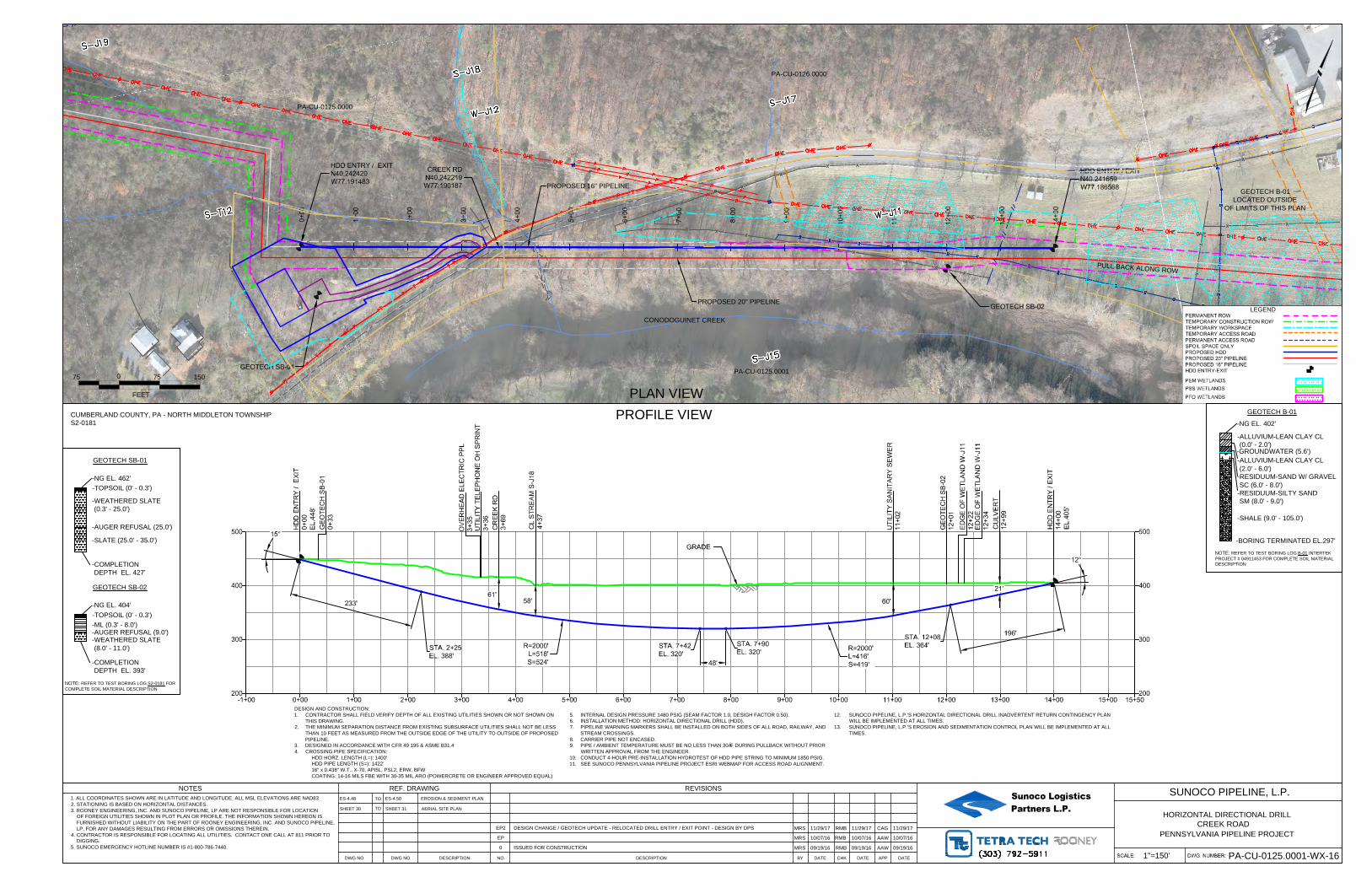
CREEK RD
N40.242219
W77.190187
0+
00
1+
00
2+
00
3+
00
4+
00
5+
00
6+
00
7+
00
8+
00
9+
00
10+
00
11+
00
12+
00
13+
00
14+
00
HDD ENTRY / EXIT
N40.242420
W77.191483
GEOTECH SB-01
GEOTECH SB-02
HDD ENTRY / EXIT
N40.241659
W77.186568
200
300
400
500
200
300
400
500
-1+00 0+00 1+00 2+00 3+00 4+00 5+00 6+00 7+00 8+00 9+00 10+00 11+00 12+00 13+00 14+00 15+00 15+50
233'
196'
12°
STA. 2+25
EL. 388'
STA. 12+08
EL. 364'
GRADE
48'
STA. 7+90
EL. 320'
STA. 7+42
EL. 320'
58'
CR
EE
K R
D
3+
69
OV
ER
HE
AD
E
LE
CT
RIC
P
PL
3+
35
UT
ILIT
Y T
ELE
PH
ON
E O
H S
PR
IN
T
3+
36
HD
D E
NT
RY
/ E
XIT
0+
00
EL.448'
HD
D E
NT
RY
/ E
XIT
14+
00
EL.405'
61'
15°
GE
OT
EC
H S
B-02
12+
01
GE
OT
EC
H S
B-01
0+
33
CL S
TR
EA
M S
-J18
4+
37
CU
LV
ER
T
12+
99
UT
ILIT
Y S
AN
IT
AR
Y S
EW
ER
11+
02
21'
60'
R=2000'
L=518'
S=524'
R=2000'
L=416'
S=419'
ED
GE
O
F W
ET
LA
ND
W
-J11
12+
34
ED
GE
O
F W
ET
LA
ND
W
-J11
12+
22
PA-CU-0125.0000
CONODOGUINET CREEK
0
FEET
75 75 150
PROPOSED 20" PIPELINE
LEGEND
PERMANENT ROW
TEMPORARY CONSTRUCTION ROW
TEMPORARY WORKSPACE
TEMPORARY ACCESS ROAD
PERMANENT ACCESS ROAD
SPOIL SPACE ONLY
PROPOSED HDD
PROPOSED 20" PIPELINE
PROPOSED 16" PIPELINE
HDD ENTRY-EXIT
PEM WETLANDS
PSS WETLANDS
PFO WETLANDS
PLAN VIEW
PROFILE VIEW
Sunoco LogisticsPartners L.P.
HORIZONTAL DIRECTIONAL DRILL
SUNOCO PIPELINE, L.P.
PENNSYLVANIA PIPELINE PROJECT
DESIGN AND CONSTRUCTION:
1. CONTRACTOR SHALL FIELD VERIFY DEPTH OF ALL EXISTING UTILITIES SHOWN OR NOT SHOWN ON
THIS DRAWING.
2. THE MINIMUM SEPARATION DISTANCE FROM EXISTING SUBSURFACE UTILITIES SHALL NOT BE LESS
THAN 10 FEET AS MEASURED FROM THE OUTSIDE EDGE OF THE UTILITY TO OUTSIDE OF PROPOSED
PIPELINE.
3. DESIGNED IN ACCORDANCE WITH CFR 49 195 & ASME B31.4
4. CROSSING PIPE SPECIFICATION:
HDD HORZ. LENGTH (L=):
HDD PIPE LENGTH (S=):
16" x 0.438" W.T., X-70, API5L, PSL2, ERW, BFW
COATING: 14-16 MILS FBE WITH 30-35 MIL ARO (POWERCRETE OR ENGINEER APPROVED EQUAL)
5. INTERNAL DESIGN PRESSURE 1480 PSIG (SEAM FACTOR 1.0, DESIGH FACTOR 0.50).
6. INSTALLATION METHOD: HORIZONTAL DIRECTIONAL DRILL (HDD).
7. PIPELINE WARNING MARKERS SHALL BE INSTALLED ON BOTH SIDES OF ALL ROAD, RAILWAY, AND
STREAM CROSSINGS.
8. CARRIER PIPE NOT ENCASED.
9. PIPE / AMBIENT TEMPERATURE MUST BE NO LESS THAN 30°F DURING PULLBACK WITHOUT PRIOR
WRITTEN APPROVAL FROM THE ENGINEER.
10. CONDUCT 4-HOUR PRE-INSTALLATION HYDROTEST OF HDD PIPE STRING TO MINIMUM 1850 PSIG.
11. SEE SUNOCO PENNSYLVANIA PIPELINE PROJECT ESRI WEBMAP FOR ACCESS ROAD ALIGNMENT.
12. SUNOCO PIPELINE, L.P.'S HORIZONTAL DIRECTIONAL DRILL INADVERTENT RETURN CONTINGENCY PLAN
WILL BE IMPLEMENTED AT ALL TIMES.
13. SUNOCO PIPELINE, L.P.'S EROSION AND SEDIMENTATION CONTROL PLAN WILL BE IMPLEMENTED AT ALL
TIMES.
PA-CU-0126.0000
PU
LL B
AC
K A
LO
NG
RO
W
NOTE: REFER TO TEST BORING LOG S2-0181 FOR
COMPLETE SOIL MATERIAL DESCRIPTION
GEOTECH SB-01
-NG EL. 462'
-TOPSOIL (0' - 0.3')
-COMPLETION
DEPTH EL. 427'
-WEATHERED SLATE
(0.3' - 25.0')
-AUGER REFUSAL (25.0')
-SLATE (25.0' - 35.0')
GEOTECH SB-02
-NG EL. 404'
-TOPSOIL (0' - 0.3')
-COMPLETION
DEPTH EL. 393'
-ML (0.3' - 8.0')
-WEATHERED SLATE
(8.0' - 11.0')
-AUGER REFUSAL (9.0')
PA-CU-0125.0001
PROPOSED 16" PIPELINE
GEOTECH B-01
-NG EL. 402'
-BORING TERMINATED EL.297'
-SHALE (9.0' - 105.0')
NOTE: REFER TO TEST BORING LOG B-01 INTERTEK
PROJECT # 04911453 FOR COMPLETE SOIL MATERIAL
DESCRIPTION
-ALLUVIUM-LEAN CLAY CL
(0.0' - 2.0')
-RESIDUUM-SAND W/ GRAVEL
SC (6.0' - 8.0')
-ALLUVIUM-LEAN CLAY CL
(2.0' - 6.0')
-RESIDUUM-SILTY SAND
SM (8.0' - 9.0')
-GROUNDWATER (5.6')
GEOTECH B-01
LOCATED OUTSIDE
OF LIMITS OF THIS PLAN
CREEK ROAD
1"=150'
PA-CU-0125.0001-WX-16
CUMBERLAND COUNTY, PA - NORTH MIDDLETON TOWNSHIP
S2-0181
1400'
1422'
REF. DRAWING
EROSION & SEDIMENT PLAN
AERIAL SITE PLAN
NO. DESCRIPTION DATEBY CHK DATE
REVISIONS
DATEAPP
NOTES
1. ALL COORDINATES SHOWN ARE IN LATITUDE AND LONGITUDE. ALL MSL ELEVATIONS ARE NAD83
2. STATIONING IS BASED ON HORIZONTAL DISTANCES.
3. ROONEY ENGINEERING, INC. AND SUNOCO PIPELINE, LP ARE NOT RESPONSIBLE FOR LOCATION
OF FOREIGN UTILITIES SHOWN IN PLOT PLAN OR PROFILE. THE INFORMATION SHOWN HEREON IS
FURNISHED WITHOUT LIABILITY ON THE PART OF ROONEY ENGINEERING, INC. AND SUNOCO PIPELINE,
LP, FOR ANY DAMAGES RESULTING FROM ERRORS OR OMISSIONS THEREIN.
4. CONTRACTOR IS RESPONSIBLE FOR LOCATING ALL UTILITIES. CONTACT ONE CALL AT 811 PRIOR TO
DIGGING.
5. SUNOCO EMERGENCY HOTLINE NUMBER IS #1-800-786-7440.
TO
TO
DWG NO DWG NO DESCRIPTION
09/19/160 ISSUED FOR CONSTRUCTION
MRS RMB AAW09/19/1609/19/16
10/07/16
ES-4.48
SHEET 31
EP2
ES-4.50
EP MRS RMB AAW10/07/16
SHEET 30
10/07/16
DESIGN CHANGE / GEOTECH UPDATE - RELOCATED DRILL ENTRY / EXIT POINT - DESIGN BY DPSMRS RMB CAG11/29/17 11/29/17 11/29/17