Embed Size (px)
Citation preview

Horizontal Gun Movers
Customer Product ManualPart 331284D
NORDSON CORPORATION � AMHERST, OHIO � USA
� 2001 Nordson CorporationAll rights reserved
331284DIssued 6/01
Manual 35-27
Nordson Corporation welcomes requests for information, comments and inquiries about its products. Generalinformation about Nordson can be found on the Internet using the following address: http://www.nordson.com.
Address all correspondence to:
Nordson CorporationAttn: Customer Service
555 Jackson StreetAmherst, OH 44001
Notice
This is a Nordson Corporation publication which is protected by copyright. Original copyright date 1999. No part of this document may be photocopied, reproduced, or translated to another language without the prior written
consent of Nordson Corporation. The information contained in this publication is subject to change without notice.
Trademarks
AccuJet, AquaGuard, Asymtek, Automove, Autotech, Blue Box, CF, CanWorks, Century, Clean Coat, CleanSleeve,CleanSpray, Compumelt, Control Coat, Cross-Cut, Cyclo-Kinetic, Dispensejet, DispenseMate, Durafiber, Durasystem,Easy Coat, Easymove Plus, Econo-Coat, EPREG, ETI, Excel 2000, Flex-O-Coat, FlexiCoat, Flexi-Spray, Flow Sentry,
Fluidmove, Fluidshooter, FoamMelt, FoamMix, Helix, Horizon, Hose Mole, Hot Shot, Hot Stitch, Isocoil, Isocore, Iso-Flo, JR,KB30, Little Squirt, Magnastatic, MEG, Meltex, MicroSet, Millenium, Mini Squirt, Moist-Cure, Mountaingate, MultiScan,
Nordson, OmniScan, Opticoat, Package of Values, PluraFoam, Porous Coat, PowderGrid, Powderware, Pro-Flo, ProLink,Pro-Meter, Pro-Stream, PRX, RBX, Ready Cost, Rhino, S. design stylized, Saturn, SC5, SCF, Select Charge, Select Coat,Select Cure, Shur-Lok, Slautterback, Smart-Coat, Spray Squirt, Spraymelt, Super Squirt, Sure-Bond, Sure Coat, System
Sentry, Tela-Therm, Trends, Tribomatic, UniScan, UpTime, Veritec, Versa-Coat, Versa-Screen, Versa-Spray, Watermark, andWhen you expect more. are registered trademarks of Nordson Corporation.
ATS, Auto-Flo, AutoScan, BetterBook, Chameleon, CanNeck, Check Mate, CPX, Control Weave, Controlled Fiberization,EasyClean, Ebraid, Eclipse, Equi=Bead, Fillmaster, Gluie, Ink-Dot, Kinetix, Maxima, MicroFin, Minimeter, Multifil, OptiMix,Pattern View, PluraMix, Primarc, Prism, Process Sentry, PurTech, Pulse Spray, Seal Sentry, Select Series, Sensomatic,
Shaftshield, Spectral, Spectrum, Sure Brand, Swirl Coat, Vista, Walcom, and 2 Rings (Design)are trademarks of Nordson Corporation.
Table of Contents i
� 2001 Nordson CorporationAll rights reserved
331284DIssued 6/01
Manual 35-27
Table of Contents
1. Safety 1. . . . . . . . . . . . . . . . . . . . . . . . . . . . . . . . . . . . . . . . . . . . . . . . . . . . .
Qualified Personnel 1. . . . . . . . . . . . . . . . . . . . . . . . . . . . . . . . . . . . . . .
Intended Use 1. . . . . . . . . . . . . . . . . . . . . . . . . . . . . . . . . . . . . . . . . . . . .
Regulations and Approvals 1. . . . . . . . . . . . . . . . . . . . . . . . . . . . . . . . .
Personal Safety 2. . . . . . . . . . . . . . . . . . . . . . . . . . . . . . . . . . . . . . . . . . .
Fire Safety 2. . . . . . . . . . . . . . . . . . . . . . . . . . . . . . . . . . . . . . . . . . . . . . .
Grounding 3. . . . . . . . . . . . . . . . . . . . . . . . . . . . . . . . . . . . . . . . . . . . . . .
Action in the Event of a Malfunction 4. . . . . . . . . . . . . . . . . . . . . . . . .
Disposal 4. . . . . . . . . . . . . . . . . . . . . . . . . . . . . . . . . . . . . . . . . . . . . . . . .
2. Description 4. . . . . . . . . . . . . . . . . . . . . . . . . . . . . . . . . . . . . . . . . . . . . . . . .
Manual Gun Movers 6. . . . . . . . . . . . . . . . . . . . . . . . . . . . . . . . . . . . . . .
Automatic Gun Movers 6. . . . . . . . . . . . . . . . . . . . . . . . . . . . . . . . . . . .
Theory of Operation—Automatic Gun Movers 7. . . . . . . . . . . . . .
Specifications 8. . . . . . . . . . . . . . . . . . . . . . . . . . . . . . . . . . . . . . . . . . . .
3. Installation 10. . . . . . . . . . . . . . . . . . . . . . . . . . . . . . . . . . . . . . . . . . . . . . . .
4. Operation 11. . . . . . . . . . . . . . . . . . . . . . . . . . . . . . . . . . . . . . . . . . . . . . . . .
Manual Gun Mover Positioning 11. . . . . . . . . . . . . . . . . . . . . . . . . . . .
Automatic Gun Mover Positioning 12. . . . . . . . . . . . . . . . . . . . . . . . . .
Startup 12. . . . . . . . . . . . . . . . . . . . . . . . . . . . . . . . . . . . . . . . . . . . . . .
Shutdown 12. . . . . . . . . . . . . . . . . . . . . . . . . . . . . . . . . . . . . . . . . . . .
5. Maintenance 13. . . . . . . . . . . . . . . . . . . . . . . . . . . . . . . . . . . . . . . . . . . . . . .
6. Repair 13. . . . . . . . . . . . . . . . . . . . . . . . . . . . . . . . . . . . . . . . . . . . . . . . . . . .
7. Parts 14. . . . . . . . . . . . . . . . . . . . . . . . . . . . . . . . . . . . . . . . . . . . . . . . . . . . .
Using the Illustrated Parts List 14. . . . . . . . . . . . . . . . . . . . . . . . . . . . .
Manual Gun Mover Parts 15. . . . . . . . . . . . . . . . . . . . . . . . . . . . . . . . .
Automatic Gun Mover Parts 16. . . . . . . . . . . . . . . . . . . . . . . . . . . . . . .

Table of Contentsii
� 2001 Nordson CorporationAll rights reserved
331284DIssued 6/01
Manual 35-27

Horizontal Gun Movers 1
� 2001 Nordson CorporationAll rights reserved
331284DIssued 6/01
Manual 35-27
Horizontal Gun Movers
Read and follow these safety instructions. Task- and equipment-specificwarnings, cautions, and instructions are included in equipmentdocumentation where appropriate.
Make sure all equipment documentation, including these instructions, isaccessible to all persons operating or servicing equipment.
Equipment owners are responsible for making sure that Nordsonequipment is installed, operated, and serviced by qualified personnel.Qualified personnel are those employees or contractors who are trainedto safely perform their assigned tasks. They are familiar with all relevantsafety rules and regulations and are physically capable of performingtheir assigned tasks.
Use of Nordson equipment in ways other than those described in thedocumentation supplied with the equipment may result in injury topersons or damage to property.
Some examples of unintended use of equipment include
� using incompatible materials� making unauthorized modifications� removing or bypassing safety guards or interlocks� using incompatible or damaged parts� using unapproved auxiliary equipment� operating equipment in excess of maximum ratings
Make sure all equipment is rated and approved for the environment inwhich it is used. Any approvals obtained for Nordson equipment will bevoided if instructions for installation, operation, and service are notfollowed.
All phases of equipment installation must comply with all federal, state,and local codes.
1. Safety
Qualified Personnel
Intended Use
Regulations and Approvals

Horizontal Gun Movers2
� 2001 Nordson CorporationAll rights reserved
331284DIssued 6/01
Manual 35-27
To prevent injury follow these instructions.
� Do not operate or service equipment unless you are qualified.
� Do not operate equipment unless safety guards, doors, or covers areintact and automatic interlocks are operating properly. Do not bypassor disarm any safety devices.
� Keep clear of moving equipment. Before adjusting or servicing anymoving equipment, shut off the power supply and wait until theequipment comes to a complete stop. Lock out power and secure theequipment to prevent unexpected movement.
� Relieve (bleed off) hydraulic and pneumatic pressure before adjustingor servicing pressurized systems or components. Disconnect, lockout, and tag switches before servicing electrical equipment.
� Obtain and read Material Safety Data Sheets (MSDS) for all materialsused. Follow the manufacturer’s instructions for safe handling anduse of materials, and use recommended personal protection devices.
� To prevent injury, be aware of less-obvious dangers in the workplacethat often cannot be completely eliminated, such as hot surfaces,sharp edges, energized electrical circuits, and moving parts thatcannot be enclosed or otherwise guarded for practical reasons.
To avoid a fire or explosion, follow these instructions.
� Do not smoke, weld, grind, or use open flames where flammablematerials are being used or stored.
� Provide adequate ventilation to prevent dangerous concentrations ofvolatile materials or vapors. Refer to local codes or your materialMSDS for guidance.
� Do not disconnect live electrical circuits while working with flammablematerials. Shut off power at a disconnect switch first to preventsparking.
Personal Safety
Fire Safety

Horizontal Gun Movers 3
� 2001 Nordson CorporationAll rights reserved
331284DIssued 6/01
Manual 35-27
� Know where emergency stop buttons, shutoff valves, and fireextinguishers are located. If a fire starts in a spray booth,immediately shut off the spray system and exhaust fans.
� Clean, maintain, test, and repair equipment according to theinstructions in your equipment documentation.
� Use only replacement parts that are designed for use with originalequipment. Contact your Nordson representative for partsinformation and advice.
WARNING: Operating faulty electrostatic equipment ishazardous and can cause electrocution, fire, or explosion.Make resistance checks part of your periodic maintenanceprogram. If you receive even a slight electrical shock or noticestatic sparking or arcing, shut down all electrical or electrostaticequipment immediately. Do not restart the equipment until theproblem has been identified and corrected.
All work conducted inside the spray booth or within 1 m (3 ft) of boothopenings is considered within a Class 2, Division 1 or 2 Hazardouslocation and must comply with NFPA 33, NFPA 70 (NEC articles 500,502, and 516), and NFPA 77, latest conditions.
� All electrically conductive objects in the spray areas shall beelectrically connected to ground with a resistance of not more than1 megohm as measured with an instrument that applies at least500 volts to the circuit being evaluated.
� Equipment to be grounded includes, but is not limited to, the floor ofthe spray area, operator platforms, hoppers, photoeye supports, andblow-off nozzles. Personnel working in the spray area must begrounded.
� There is a possible ignition potential from the charged human body.Personnel standing on a painted surface, such as an operatorplatform, or wearing non-conductive shoes, are not grounded.Personnel must wear shoes with conductive soles or use a groundstrap to maintain a connection to ground when working with or aroundelectrostatic equipment.
� Operators must maintain skin-to-handle contact between their handand the gun handle to prevent shocks while operating manualelectrostatic spray guns. If gloves must be worn, cut away the palmor fingers, wear electrically conductive gloves, or wear a groundingstrap connected to the gun handle or other true earth ground.
Grounding
Horizontal Gun Movers4
� 2001 Nordson CorporationAll rights reserved
331284DIssued 6/01
Manual 35-27
� Shut off electrostatic power supplies and ground gun electrodesbefore making adjustments or cleaning powder spray guns.
� Connect all disconnected equipment, ground cables, and wires afterservicing equipment.
If a system or any equipment in a system malfunctions, shut off thesystem immediately and perform the following steps:
� Disconnect and lock out electrical power. Close pneumatic shutoffvalves and relieve pressures.
� Identify the reason for the malfunction and correct it before restartingthe equipment.
Dispose of equipment and materials used in operation and servicingaccording to local codes.
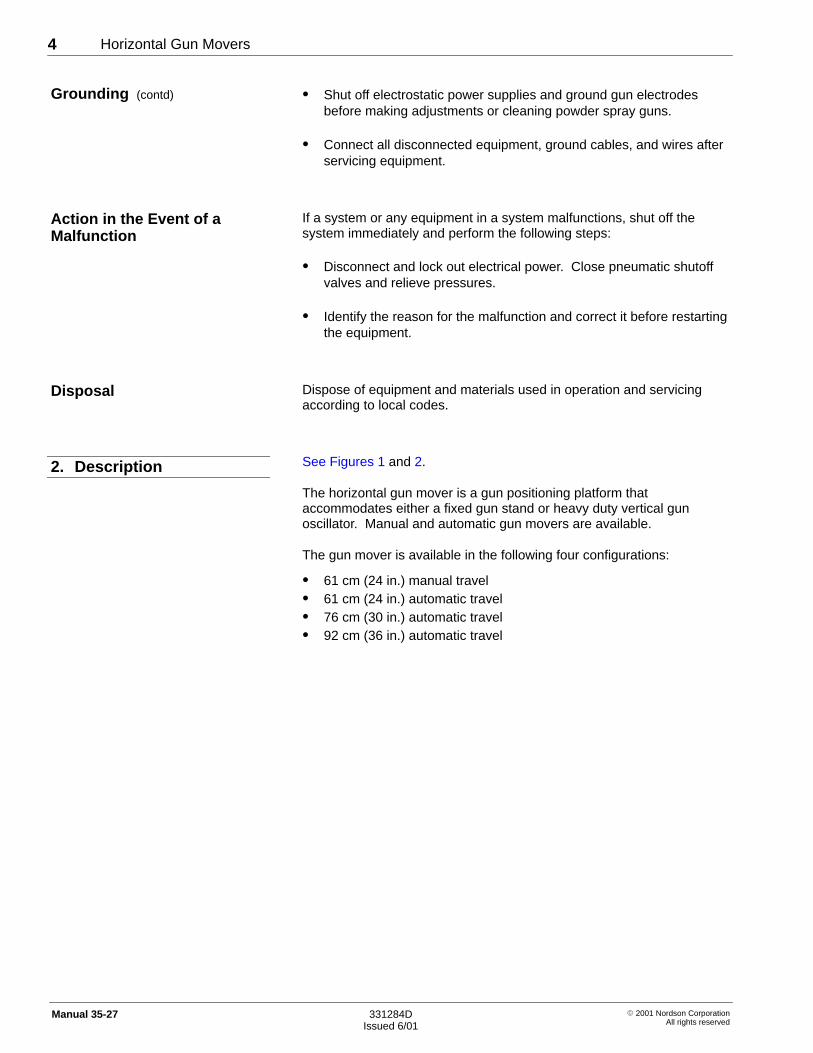
See Figures 1 and 2.
The horizontal gun mover is a gun positioning platform thataccommodates either a fixed gun stand or heavy duty vertical gunoscillator. Manual and automatic gun movers are available.
The gun mover is available in the following four configurations:
� 61 cm (24 in.) manual travel� 61 cm (24 in.) automatic travel� 76 cm (30 in.) automatic travel� 92 cm (36 in.) automatic travel
Grounding (contd)
Action in the Event of aMalfunction
Disposal
2. Description

Horizontal Gun Movers 5
� 2001 Nordson CorporationAll rights reserved
331284DIssued 6/01
Manual 35-27
3527006A
Fig. 1 Manual Horizontal Gun Mover (Shown with Fixed Gun Stand)
3527001C
Fig. 2 Automatic Horizontal Gun Mover (Shown with Vertical Oscillator)
Horizontal Gun Movers6
� 2001 Nordson CorporationAll rights reserved
331284DIssued 6/01
Manual 35-27
The operator positions the oscillator plate by hand. The manual gunmover has a knob that locks the oscillator plate to the gun mover frame,which prevents unwanted movement after the oscillator plate has beenpositioned.
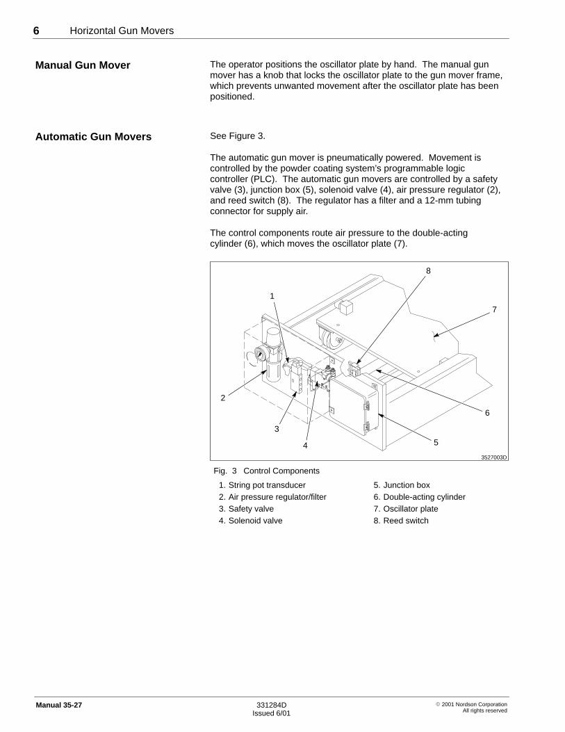
See Figure 3.
The automatic gun mover is pneumatically powered. Movement iscontrolled by the powder coating system’s programmable logiccontroller (PLC). The automatic gun movers are controlled by a safetyvalve (3), junction box (5), solenoid valve (4), air pressure regulator (2),and reed switch (8). The regulator has a filter and a 12-mm tubingconnector for supply air.
The control components route air pressure to the double-actingcylinder (6), which moves the oscillator plate (7).
3527003D
6
3
4
2
8
1
5
7
Fig. 3 Control Components
1. String pot transducer2. Air pressure regulator/filter3. Safety valve4. Solenoid valve
5. Junction box6. Double-acting cylinder7. Oscillator plate8. Reed switch
Manual Gun Mover
Automatic Gun Movers
Horizontal Gun Movers 7
� 2001 Nordson CorporationAll rights reserved
331284DIssued 6/01
Manual 35-27
Theory of Operation—Automatic Gun Movers
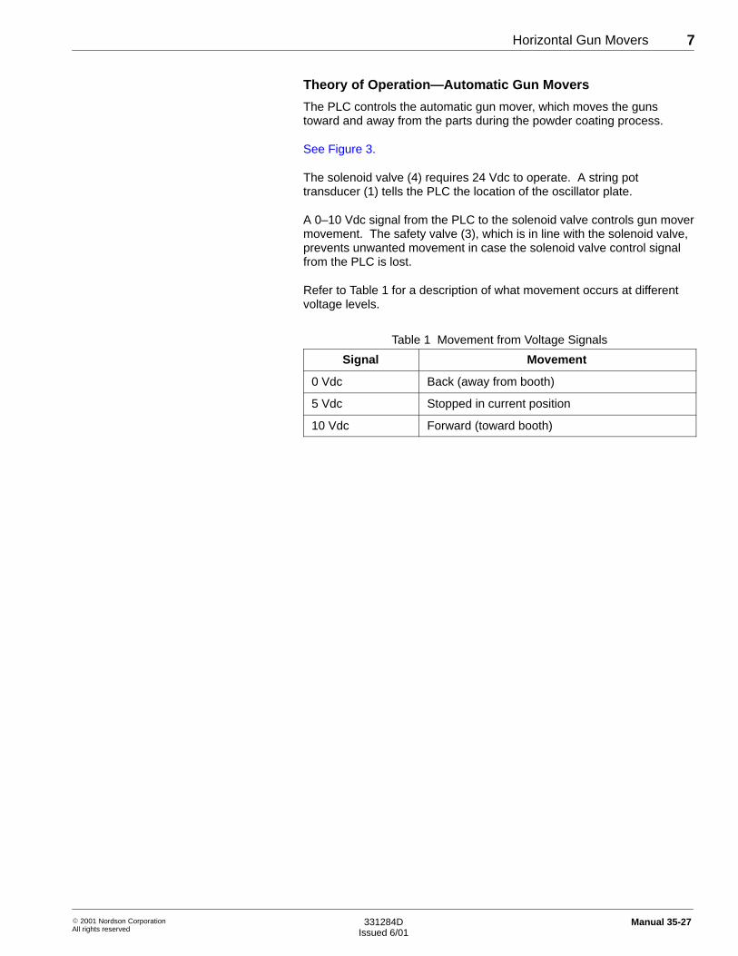
The PLC controls the automatic gun mover, which moves the gunstoward and away from the parts during the powder coating process.
See Figure 3.
The solenoid valve (4) requires 24 Vdc to operate. A string pottransducer (1) tells the PLC the location of the oscillator plate.
A 0–10 Vdc signal from the PLC to the solenoid valve controls gun movermovement. The safety valve (3), which is in line with the solenoid valve,prevents unwanted movement in case the solenoid valve control signalfrom the PLC is lost.
Refer to Table 1 for a description of what movement occurs at differentvoltage levels.
Table 1 Movement from Voltage Signals
Signal Movement
0 Vdc Back (away from booth)
5 Vdc Stopped in current position
10 Vdc Forward (toward booth)
Horizontal Gun Movers8
� 2001 Nordson CorporationAll rights reserved
331284DIssued 6/01
Manual 35-27
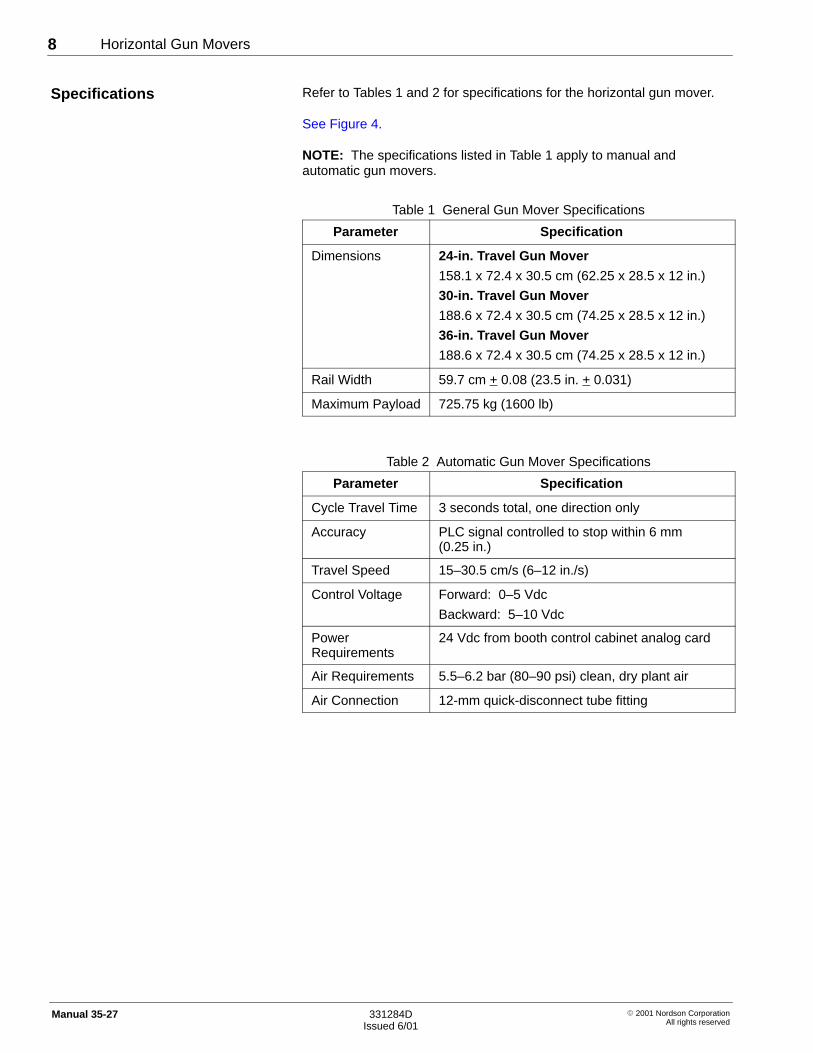
Refer to Tables 1 and 2 for specifications for the horizontal gun mover.
See Figure 4.
NOTE: The specifications listed in Table 1 apply to manual andautomatic gun movers.
Table 1 General Gun Mover Specifications
Parameter Specification
Dimensions 24-in. Travel Gun Mover
158.1 x 72.4 x 30.5 cm (62.25 x 28.5 x 12 in.)
30-in. Travel Gun Mover
188.6 x 72.4 x 30.5 cm (74.25 x 28.5 x 12 in.)
36-in. Travel Gun Mover
188.6 x 72.4 x 30.5 cm (74.25 x 28.5 x 12 in.)
Rail Width 59.7 cm + 0.08 (23.5 in. + 0.031)
Maximum Payload 725.75 kg (1600 lb)
Table 2 Automatic Gun Mover Specifications
Parameter Specification
Cycle Travel Time 3 seconds total, one direction only
Accuracy PLC signal controlled to stop within 6 mm(0.25 in.)
Travel Speed 15–30.5 cm/s (6–12 in./s)
Control Voltage Forward: 0–5 Vdc
Backward: 5–10 Vdc
PowerRequirements
24 Vdc from booth control cabinet analog card
Air Requirements 5.5–6.2 bar (80–90 psi) clean, dry plant air
Air Connection 12-mm quick-disconnect tube fitting
Specifications

Horizontal Gun Movers 9
� 2001 Nordson CorporationAll rights reserved
331284DIssued 6/01
Manual 35-27
3527002C
72.4 cm
30- or 36-in. travel:
30.5 cm
17.3 cm59.7 cm � 0.08(23.5 in. � 0.03)
(28.25 in.)
(12 in.)
(6.82 in.)
24-in. travel:158.1 cm (62.25 in.)
188.6 cm (74.25 in.)
Fig. 4 Manual and Automatic Gun Mover Dimensions

Horizontal Gun Movers10
� 2001 Nordson CorporationAll rights reserved
331284DIssued 6/01
Manual 35-27
WARNING: Allow only qualified personnel to perform thefollowing tasks. Follow the safety instructions in this documentand all other related documentation.
Use the following steps for basic installation of the gun mover.
NOTE: A Nordson representative must connect automatic gun movers tothe power supply and PLC.
1. Unpack the gun mover. Check for damage to the crate and the gunmover.
2. Make sure that all items listed on the packing slip are present.
NOTE: Contact the freight company and your Nordson representativeabout any loss or damage. Nordson Corporation will assist you in filingyour claim and collecting for loss or damage. This willingness to assistyou does not make Nordson Corporation responsible for collection of theclaim or replacement of any loss.
3. Place the gun mover in the final installation site.
4. Use four customer-supplied 1/2 x 21/2 in. concrete anchor bolts andlock washers to secure the gun mover to the floor.
5. Connect the included grounding strap to the gun mover’s metalframe. Connect the other end of the ground strap to the booth base.
6. If you are installing an automatic gun mover, perform these steps:
a. See Figure 3.
Connect the air line to the 12-mm main air connection on the airpressure regulator/filter (2).
b. Contact your Nordson representative to perform final installationand adjustments.
3. Installation
Horizontal Gun Movers 11
� 2001 Nordson CorporationAll rights reserved
331284DIssued 6/01
Manual 35-27
WARNING: Allow only qualified personnel to perform thefollowing tasks. Follow the safety instructions in this documentand all other related documentation.
WARNING: Make sure that all personnel and equipment areaway from the gun mover and its components before startingthe powder coating system. Make sure that nothing willinterfere with gun mover or vertical oscillator movement.Failure to observe this warning could result in personal injury ordeath.
WARNING: Do not open access panels or make adjustmentsto the gun mover or vertical oscillator while the powder coatingsystem is operating. Failure to observe this warning couldresult in equipment damage, personal injury, or death.
Use the following procedure to operate the manual horizontal gun mover.
See Figure 5.
1. Unlock the oscillator plate (5) by turning the locking knob (4)counterclockwise. The oscillator plate will move freely on the gunmover’s horizontal rails.
2. Move the oscillator plate to the desired location.
3. Line up the locking knob with one of the holes on the locking plate.
4. Lock the oscillator plate by turning the locking knob clockwise. Turnthe knob until it is hand tight.
4. Operation
Manual Gun MoverPositioning
Horizontal Gun Movers12
� 2001 Nordson CorporationAll rights reserved
331284DIssued 6/01
Manual 35-27
WARNING: Make sure that all personnel and equipment areaway from the gun mover and its components before startingthe powder coating system. Make sure that nothing willinterfere with gun mover or vertical oscillator movement.Failure to observe this warning could result in personal injury ordeath.
WARNING: Do not open access panels or make adjustmentsto the gun mover or vertical oscillator while the powder coatingsystem is operating. Failure to observe this warning couldresult in equipment damage, personal injury, or death.
Use the following procedures to operate the automatic horizontal gunmover. Contact your Nordson representative for further operatinginstructions for the gun mover and PLC.
NOTE: The gun mover will not operate if the PLC is turned off.
Startup
Use the following steps to start up the automatic gun mover.
1. Turn on the supply air.2. Set the air pressure regulator to 6 bar (90 psi).3. Adjust the movement as required through the PLC.
Shutdown
Use the following steps to shut down the automatic gun mover.
1. Stop gun mover movement at the PLC.2. Turn off the supply air.
Automatic Gun MoverPositioning

Horizontal Gun Movers 13
� 2001 Nordson CorporationAll rights reserved
331284DIssued 6/01
Manual 35-27
WARNING: Allow only qualified personnel to perform thefollowing tasks. Follow the safety instructions in this documentand all other related documentation.
WARNING: Disconnect equipment from the line voltage beforeservicing the equipment. Failure to observe this warning mayresult in a severe shock.
WARNING: System or material pressurized. Relieve pressurebefore servicing equipment. Failure to observe this warningcould result in equipment damage, personal injury, or death.
CAUTION: Accumulation of dust, dirt or overspray may causeexcessive wear and premature component failure.
1. Clean the gun mover’s internal components as necessary.
2. Check for overspray build up on the tracks and the casters. Cleanthe tracks and casters as necessary.
NOTE: If the gun mover is located in an inherently dirty environmentor if the overspray build up is excessive, consider using a pressurizingunit. Contact your Nordson representative for more information onpressurizing units.
3. Automatic Gun Movers Only: Check the air pressure regulator/filtercartridge periodically and replace as necessary with aNordson-approved, 5-micron cartridge. Refer to Parts for air filtercartridge ordering information.
Repairing the horizontal gun mover requires special training. Contactyour Nordson representative for assistance.
5. Maintenance
6. Repair
Horizontal Gun Movers14
� 2001 Nordson CorporationAll rights reserved
331284DIssued 6/01
Manual 35-27
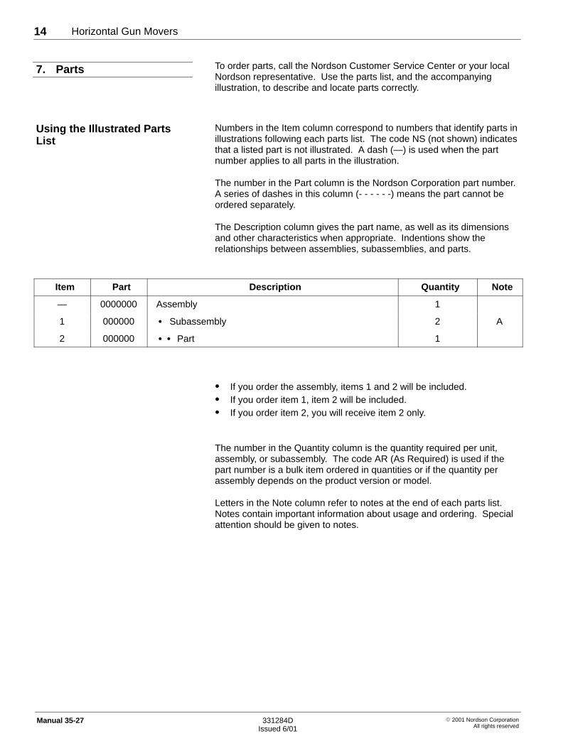
To order parts, call the Nordson Customer Service Center or your localNordson representative. Use the parts list, and the accompanyingillustration, to describe and locate parts correctly.
Numbers in the Item column correspond to numbers that identify parts inillustrations following each parts list. The code NS (not shown) indicatesthat a listed part is not illustrated. A dash (—) is used when the partnumber applies to all parts in the illustration.
The number in the Part column is the Nordson Corporation part number.A series of dashes in this column (- - - - - -) means the part cannot beordered separately.
The Description column gives the part name, as well as its dimensionsand other characteristics when appropriate. Indentions show therelationships between assemblies, subassemblies, and parts.
Item Part Description Quantity Note
— 0000000 Assembly 1
1 000000 � Subassembly 2 A
2 000000 � � Part 1
� If you order the assembly, items 1 and 2 will be included.� If you order item 1, item 2 will be included.� If you order item 2, you will receive item 2 only.
The number in the Quantity column is the quantity required per unit,assembly, or subassembly. The code AR (As Required) is used if thepart number is a bulk item ordered in quantities or if the quantity perassembly depends on the product version or model.
Letters in the Note column refer to notes at the end of each parts list.Notes contain important information about usage and ordering. Specialattention should be given to notes.
7. Parts
Using the Illustrated PartsList

Horizontal Gun Movers 15
� 2001 Nordson CorporationAll rights reserved
331284DIssued 6/01
Manual 35-27
See Figure 5.
Item Part Description Quantity Note
— 333512 Horizontal gun mover, manual, 24-in. travel 1
1 - - - - - - � Frame, base, gun mover 1
2 - - - - - - � Plate, stop, manual, gun mover 1
3 - - - - - - � Bracket, stop, manual, gun mover 1
4 1010787 � Knob, hand, aluminum, with 3/8-16 stud 1
5 - - - - - - � Plate, base, oscillator assembly 1
6 174605 � � Caster, V-groove, rigid, 4 in. 4
7 - - - - - - � � Cam, follower 4
3527005B
5
7
6
1
2
3
4
Fig. 5 Manual Gun Mover Parts
Manual Gun Mover Parts

Horizontal Gun Movers16
� 2001 Nordson CorporationAll rights reserved
331284DIssued 6/01
Manual 35-27
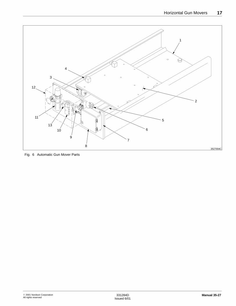
See Figure 6.
Item Part Description Quantity Note
— 333509 Horizontal gun mover, automatic, 24-in. travel 1
— 333510 Horizontal gun mover, automatic, 30-in. travel 1
— 333511 Horizontal gun mover, automatic, 36-in. travel 1
1 - - - - - - � Frame, base, gun mover 1
2 - - - - - - � Plate, base, oscillator, assembly 1
3 174605 � � Caster, V-groove, rigid, 4 in. 4
4 - - - - - - � � Cam, follower 4
5 333649 � Cylinder, air, double acting, 24-in. stroke 1
5 333655 � Cylinder, air, double acting, 30-in. stroke 1
5 333514 � Cylinder, air, rodless, 36-in. stroke 1
6 333656 � Switch, reed, proximity sensor 1
7 333662 � Panel, assembly, air control, automatic 1
8 - - - - - - � � Box, junction 1
9 333508 � � Valve, solenoid, 3-2 way, with needle valves 1
10 333658 � � Valve, directional control, servo 1
11 333660 � � Regulator, filter, 0–100 psi 1
NS 1010751 � � � Filter, 5 micron 1
12 - - - - - - � � Cover, pneumatic panel assembly 1
13 333659 � Transducer, string pot 1
NS: Not Shown
Automatic Gun Mover Parts
Horizontal Gun Movers 17
� 2001 Nordson CorporationAll rights reserved
331284DIssued 6/01
Manual 35-27
3527004C
2
5
4
8
10
9
13
11
6
3
1
12
7
Fig. 6 Automatic Gun Mover Parts

Horizontal Gun Movers18
� 2001 Nordson CorporationAll rights reserved
331284DIssued 6/01
Manual 35-27